

BG-72
Intel Pentium 4 System Board
Socket 478
User’s Manual
Rev. 1.00

Copyright and Warranty Notice
The information in this document is subject to change without notice and does not
represent a commitment on part of the vendor, who assumes no liability or
responsibility for any errors that may appear in this manual.
No warranty or representation, either expressed or implied, is made with respect to the
quality, accuracy or fitness for any particular part of this document. In no event shall
the manufacturer be liable for direct, indirect, special, incidental or consequential
damages arising from any defect or error in this manual or product.
Product names appearing in this manual are for identification purpose only and
trademarks and product names or brand names appearing in this document are
property of their respective owners.
This document contains materials protected under International Copyright Laws. All
rights reserved. No part of this manual may be reproduced, transmitted or transcribed
without the expressed written permission of the manufacturer and authors of this
manual.
BG-72

Table of Contents
Chapter 1. Introduction .................................................... 1-1
1.1. Features & Specifications...................................................... 1-1
1.2. Layout Diagram..................................................................... 1-3
1.3. Jumpers & Connectors Description....................................... 1-4
Chapter 2. Hardware Setup.............................................. 2-1
2.1. CPU Socket ........................................................................... 2-1
2.2. System Memory .................................................................... 2-2
2.3. Connectors, Headers, and Switches....................................... 2-3
2.3.1. ATX Power Connectors........................................... 2-3
2.3.2. FAN Connectors ...................................................... 2-4
2.3.3. CMOS Memory Clearing Header ............................ 2-5
2.3.4. Front Panel Switches & Indicators Connection
Headers .................................................................... 2-6
2.3.5. Additional USB Port Connection Header................ 2-7
2.3.6. Front Panel Audio Connection Header .................... 2-8
2.3.7. Internal Audio Source Connectors........................... 2-9
2.3.8. Floppy Disk Drive Connector................................ 2-10
2.3.9. IDE Disk Drive Connectors................................... 2-11
2.3.10. External I/O Panel.................................................. 2-12
Chapter 3. BIOS Setup...................................................... 3-1
3.1. About the Setup Utility ......................................................... 3-1
3.1.1. The Standard Configuration..................................... 3-2
3.1.2. Entering the Setup Utility ........................................ 3-3
3.1.3. Updating the BIOS................................................... 3-4
3.2. Using BIOS ........................................................................... 3-5
3.2.1. Standard CMOS Features ........................................ 3-5
3.2.2. Advanced BIOS Features......................................... 3-9
3.2.3. Advanced Chipset Features ................................... 3-13
3.2.4. Integrated Peripherals ............................................ 3-16
User’s Manual

3.2.5. Power Management Setup ..................................... 3-20
3.2.6. PnP/PCI Configurations......................................... 3-23
3.2.7. PC Health Status .................................................... 3-26
3.2.8. Frequency/Voltage Control.................................... 3-27
3.2.9. Load Fail-Safe Defaults Option............................. 3-28
3.2.10. Load Optimized Defaults Option........................... 3-28
3.2.11. Set Supervisor Password/Set User Password......... 3-28
3.2.12. Save & Exit Setup.................................................. 3-29
3.2.13. Exit Without Saving............................................... 3-29
Chapter 4. Driver Installation .......................................... 4-1
4.1. Setup Items............................................................................ 4-2
Appendix A. How to Get Technical Support ..................... A-1
BG-72

Introduction 1-1
Chapter 1. Introduction
1.1. Features & Specifications
CPU
• Supports Intel
processors with 400/533 MHz FSB
®
Pentium 4 Prescott 533/Celeron D/Celeron Socket 478
Chipset
• Intel
• Intel
®
845GV
®
ICH4
Memory
• Two 184-pin DIMM slots
• Supports DDR 200/266/333 non-ECC un-buffered memory
• Supports maximum memory capacity up to 2GB
Graphic
• Integrated Graphic Architecture yields higher 2D/3D performance
LAN
• Onboard 10/100M PCI controller
Audio
• Onboard 5.1-channel Audio CODEC
Internal I/O Connectors
• 3x PCI slots
• 1x Floppy Port supports up to 2.88MB
• 2x Ultra DMA 100/66/33 Connectors
• 2x USB 2.0 headers (Each header support two USB 2.0 devices)
• 1x FP-Audio header, 1x CD-IN connector
Back Panel I/O
• 1x PS/2 Keyboard, 1x PS/2 Mouse
• 1x Serial Port, 1x Parallel Port, 1x VGA connector
• 2x USB 2.0, 1x RJ-45 LAN Connector
• 1x Audio connector (Line-in, Line-out, Mic-in)
User’s Manual

1-2 Chapter 1
Miscellaneous
• Micro ATX form factor (244mm x 200mm)
! All brand names and trademarks are the property of their respective
owners.
! This motherboard is customized for certain system configurations; and
may not fit system integration in all DIY ways. Before integrating this
product, please check ABIT web site for recommended device listings, or
contact sales/tech. support people.
! Specifications and information contained herein are subject to change
without notice.
BG-72
Introduction 1-3
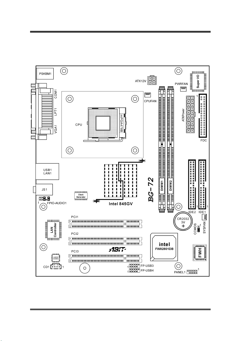
1.2. Layout Diagram
User’s Manual

1-4 Chapter 1
1.3. Jumpers & Connectors Description
Jumpers Description Default Setting
CCMOS CMOS Memory Clearing Header Pins 2-3 Closed (Normal)
Connectors Description
ATXPower
ATX12V
CD1 Internal Audio Connector
CPUFAN
SYSFAN
PWRFAN
DIMM1/DIMM2 DDR DIMM Slots
FDC Floppy Disk Drive Connector
FPIO-AUDIO1 Front Panel Audio Connection Header
IDE1/IDE2 Hard Disk Drive Connectors
PANEL1 Front Panel Switch Connection Header
PCI1/PCI2/PCI3 32bit/33MHz PCI Slots
FP-USB3/FP-USB4 Additional USB Port Connection Headers
ATX Power Connectors
CPU Fan Power Connector
System Fan Power Connector
Power Fan Power Connector
BG-72
Hardware Setup 2-1
Chapter 2. Hardware Setup
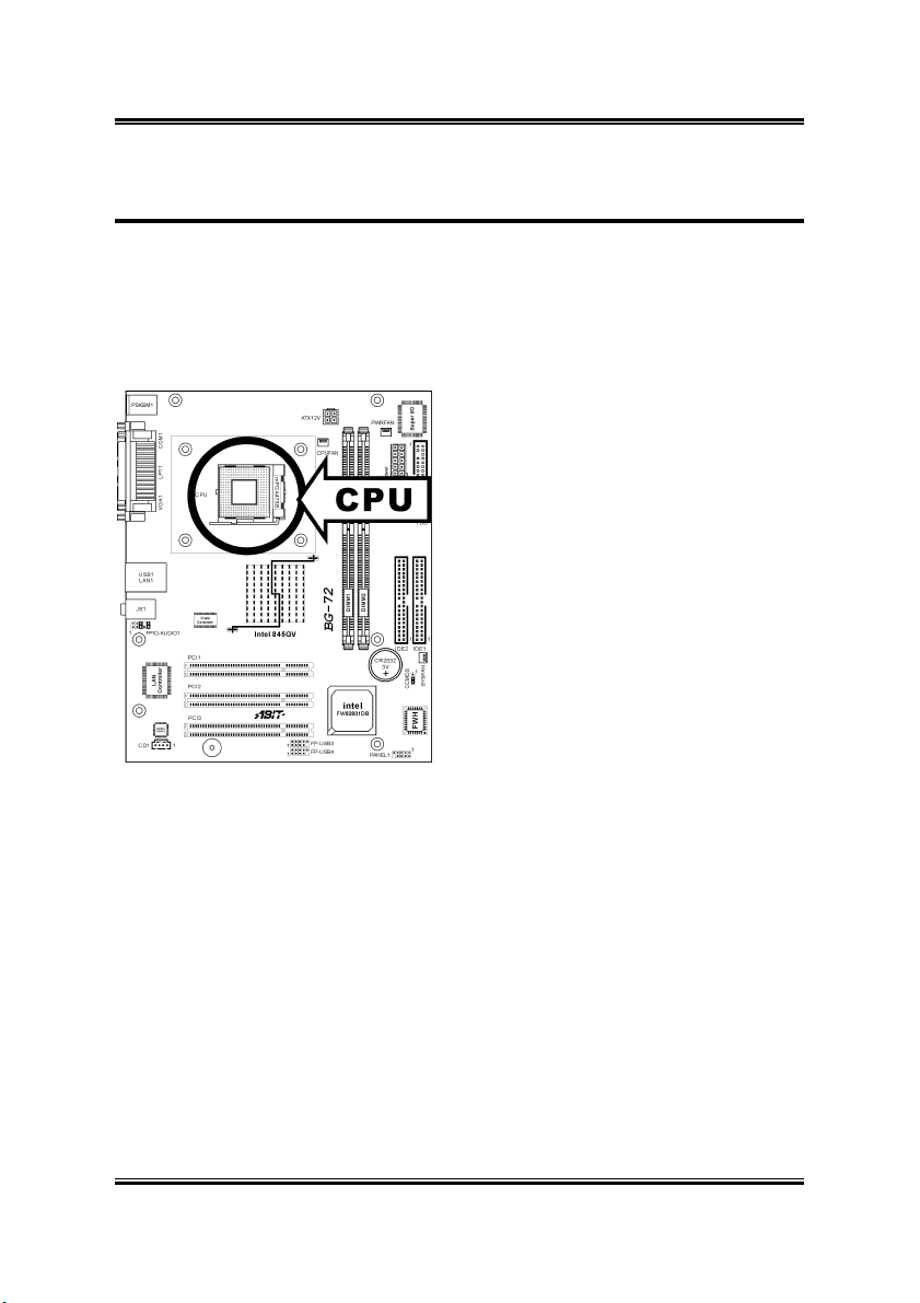
2.1. CPU Socket
This server board provides one 478-pin Zero Insertion Force (ZIF) socket to install the
Intel Pentium 4 CPU.
User’s Manual
2-2 Chapter 2
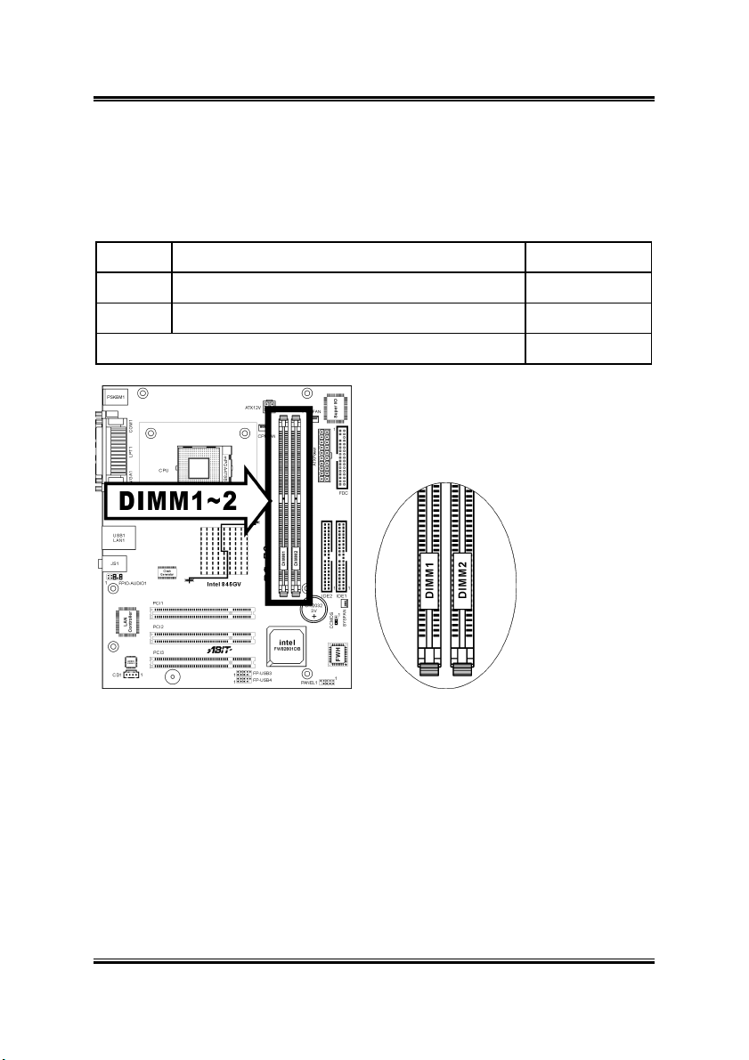
2.2. System Memory
This system board provides two 184-pin DDR DIMM slots for un-buffered and
non-ECC modules with memory size expansible up to 2GB (DDR333).
DIMM DIMM Module Total Memory
1 256MB, 512MB, 1GB 256MB ~ 1GB
2 256MB, 512MB, 1GB 256MB ~ 1GB
Total System Memory
256MB ~ 2GB
BG-72
Hardware Setup 2-3
2.3. Connectors, Headers, and Switches
All the connectors, headers and switches mentioned here are depending on your
system configuration. Some features you may (or may not) have to connect or to
configure depending on the peripherals you have connected.
WARNING: Always power off the computer and unplug the AC power cord before
adding or removing any peripheral or component. Failing to so may cause severe
damage to your system board and/or peripherals. Plug in the AC power cord only after
you have carefully checked everything.
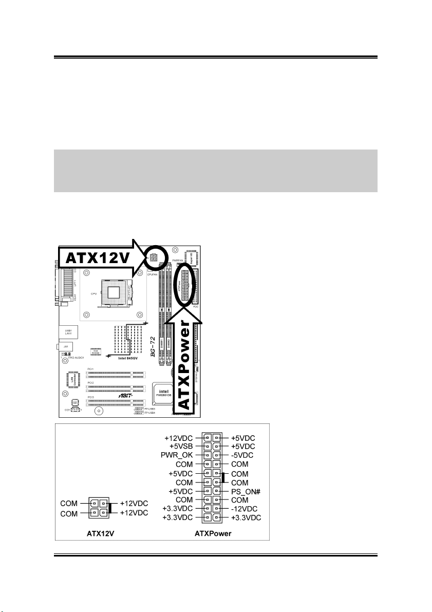
2.3.1. ATX Power Connectors
This connector provides the connection to ATX12V power supply.
User’s Manual
2-4 Chapter 2
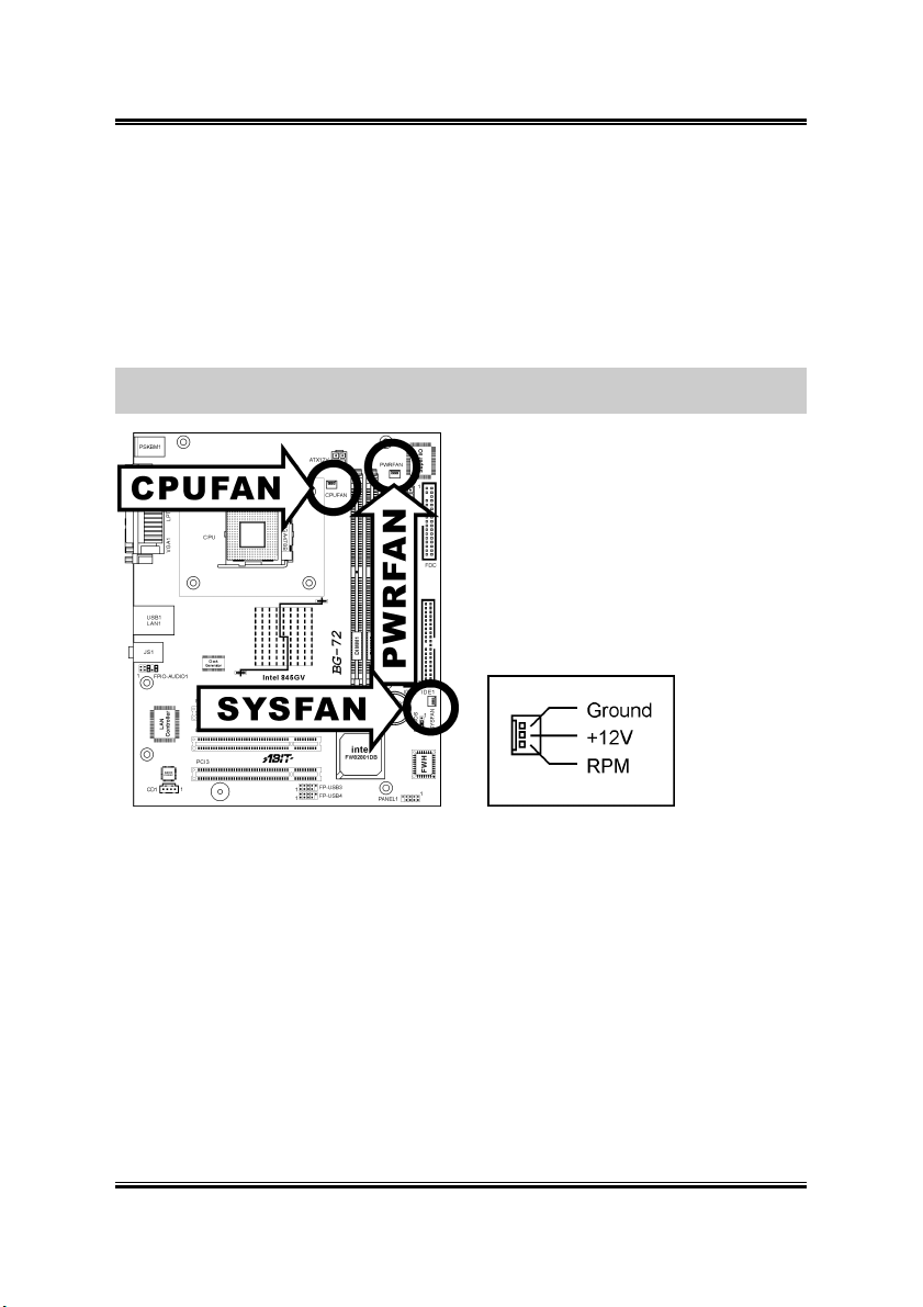
2.3.2. FAN Connectors
These connectors each provide power to the cooling fans installed in your system.
• CPUFAN: CPU Fan Power Connector
• SYSFAN: System Fan Power Connector
• PWRFAN: Power Fan Power Connector
WARNING: These fan connectors are not jumpers. DO NOT place jumper caps on
these connectors.
BG-72
Hardware Setup 2-5
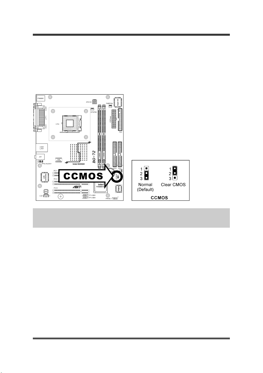
2.3.3. CMOS Memory Clearing Header
This header uses a jumper cap to clear the CMOS memory.
• Pin 2-3 shorted (default): Normal operation.
• Pin 1-2 shorted: Clear CMOS memory.
ATTENTION: Turn the system power off first (including the +5V standby power)
before clearing the CMOS memory. Failing to do so may cause your system to work
abnormally or malfunction.
User’s Manual
2-6 Chapter 2
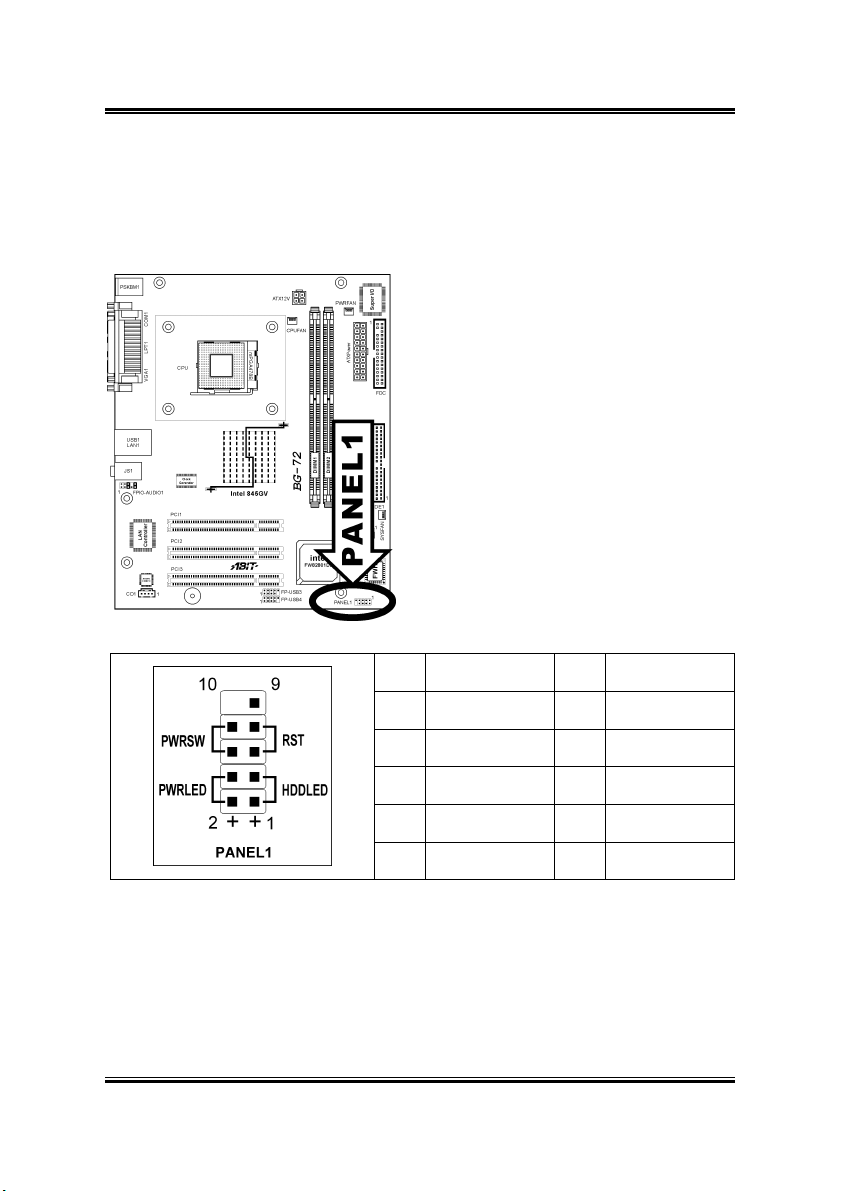
2.3.4. Front Panel Switches & Indicators Connection Headers
These headers are used for connecting switches and LED indicators on the chassis
front panel. The mark “+” align to the pin in the figure below stands for positive
polarity for the LED connection.
Pin Definition Pin Definition
BG-72
1 HD LED + 2 Power LED +
3 HD LED - 4 Power LED -
5 RESET 6 Power Switch
7 RESET 8 Power Switch
9 Reserved 10 NC

Hardware Setup 2-7
2.3.5. Additional USB Port Connection Header
These headers each provide 2 additional USB 2.0 ports connection through an USB
cable designed for USB 2.0 specifications.
Pin Signal Name Function
1 USBPWR Front Panel USB Power
2 USBPWR Front Panel USB Power
3 USB_FP_P0- USB Port 0 Negative Signal
4 USB_FP_P1- USB Port 1 Negative Signal
5 USB_FP_P0+ USB Port 0 Positive Signal
6 USB_FP_P1+ USB Port 1 Positive Signal
7 GND Ground
8 GND Ground
9 Key No pin
10 NC NC
User’s Manual
2-8 Chapter 2
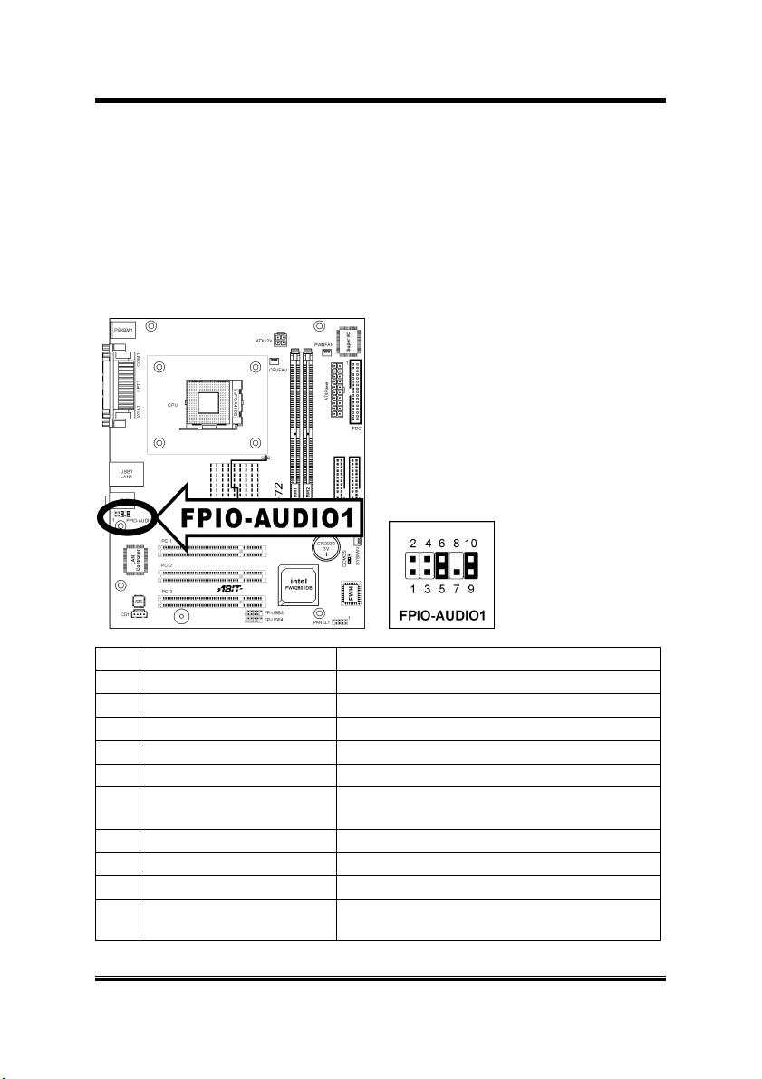
2.3.6. Front Panel Audio Connection Header
This header provides the connection to audio connector at front panel.
• To use the audio connector at front panel, remove all the jumpers on this
header, and then connect to front panel by the extension cable provided with
the chassis.
• To use the audio connector at rear panel, disconnect the extension cable,
attach the jumpers back at pin 5-6, and pin 9-10 (default setting).
Pin Signal Name Function
1 AUD_MIC Front Panel Microphone input signal
2 AUD_GND Ground used by Analog Audio Circuits
3 AUD_MIC_BIAS Microphone Power
4 AUD_VCC Filtered +5V used by Analog Audio Circuits
5 AUD_F_R Right Channel audio signal to Front Panel
6 AUD_RET_R
7 REVD Reserved
8 Key No Pin
9 AUD_F_L Left Channel Audio signal to Front Panel
10 AUD_RET_L
BG-72
Right Channel Audio signal to Return from
Front Panel
Left Channel Audio signal to Return from Front
Panel
Hardware Setup 2-9
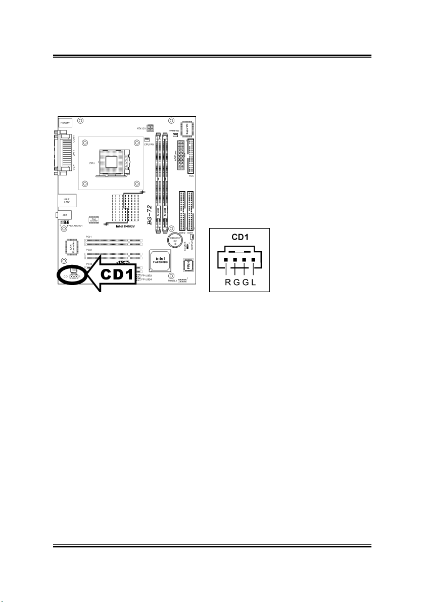
2.3.7. Internal Audio Source Connectors
This connector connects to the audio output of internal CD-ROM drive or add-on
card.
User’s Manual
 Loading...