

Page 1

Table of Contents i
Pentium Pro Mainboard
USER’S MANUAL
Table of Contents
Chapter 1 System Board Overview
Specifications.....................................................................1-1
Component Placement........................................................1-2
The system block diagram ..................................................1-3
Chapter 2 Hardware Setup
Precautions.........................................................................2-1
Connectors.........................................................................2-1
Jumper Switches.................................................................2-5
Installation of CPU.............................................................2-7
Installation of Memory .......................................................2-7
Chapter 3 Award BIOS Setup
CPU SOFT MENU............................................................3-3
Standard CMOS Setup Menu.............................................3-4
BIOS Features Setup Menu................................................3-6
Chipset Features Setup Menu.............................................3-8
Power Management Setup..................................................3-9
PCI & Onboard I/O Setup................................................3-12
Load BIOS Defaults.........................................................3-14
Load Setup Defaults.........................................................3-14
Setting Password..............................................................3-15
IDE HDD Auto Detection................................................3-15
Standard types of hard disks.............................................3-16
Part Number: MN-094-2A1-01 Rev:1.01
Page 2

ii Table of Contents
Chapter 4 Bus Master IDE Driver
Page 3

System Board Overview 1-1
Chapter 1 System Board
Overview
The mainboard is designed for the new generation CPU. It supports the Intel
CPU SLOT1(Pentium Pro, PentiumII ..), memory up to 1GB, super I/O, and
Green PC functions. The mainboard provide high performance for the server
system and meet the necessary of the desktop system for Multi-Media in the
future.
Specifications
1. CPU: Supports Intel Pentium Pro 150~200 MHz,
PentiumII 233~266 MHz
2. Chipset: Intel 82440 FX chipset
3. Memory(DRAM): Four 72PIN SIMM modules
Two 168PIN DIMM modules
Supports 8MB to 1GB memory capacity
Supports EDO and FP DRAM type
4. On board IDE: Two E-IDE channels
Supports up to 4 hard devices
5. On board FDC: Supports two floppy disk drivers up to 2.88MB
6. On board Fast I/O: One EPP/ECP parallel port (IEEE 1284
Compliant)
Two high speed 16550A Compliant UARTs
Supports Infrared – IrDA(HPSIR) and
Amplitude Shift Keyed IR(ASKIR)
Supports “PCI Bus master IDE controller” to
reduce the work load of the CPU
Supports two Universal Serial Bus (USB)
interface
Supports one PS/2 mouse connector
7. I/O slots: Four 32-bit PCI slots, three 16-bit ISA slots
8. BIOS: Award Plug and Play BIOS
9. Dimension: ATX form factor 245 x 305 mm
Page 4
1-2 Chapter 1
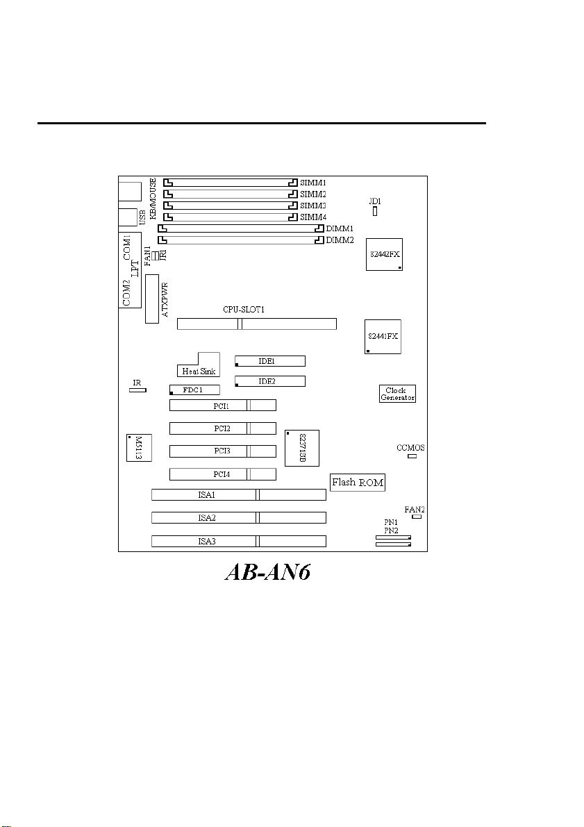
Component Placement
Figure 1-1 Component Locations
Page 5
System Board Overview 1-3
BufferKBCRTCFlash BIO
S
SerialLPTIrDAFD
C
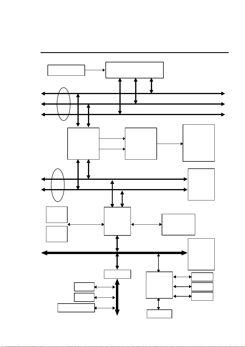
The System block diagram
VRM 8.1
Host BUS
PCI BUS
USB1
USB2
PMC
82441FX
CPU-SLOT1
Addr
Cntrl
PIIX3
Main
Memory
(DRAM)
Control
Address/Data
Control
Address
Data
Data
PCI IDE
HEADER
DBX
82442FX
PCI
SLOT(s)
ISA BUS
AIP
37C669
(M5113)
X BUS
ISA
SLOT(s)
Page 6

1-4 Chapter 1
Page 7

Hardware Setup 2-1
Chapter 2 Hardware Setup
This chapter describes the mainboard’s connectors and how to set the
mainboard’s jumpers.
Precautions
You should take the following precautions before you begin working with the
motherboard and its components:
l Turn off the mainboard’s power, and unplug the power cord.
l Unplug all cables connect the mainboard to any external devices.
Caution: Make sure you first turn off all power to the system before
attaching components to the mainboard.
Connectors
You attach system components and case devices to the mainboard’s connectors.
A description of each connector and its pin assignments follows. Refer to
Figure 1-1 for connector location on the mainboard.
PN2(Pin 4-5-6-7) - Speaker Connector
Attach the system speaker to connector PN2.
Pin Assignment
4 Speaker data
5 Ground
6 Ground
7 +5VDC
Page 8

2-2 Chapter 2
PN2(Pin 1-2) - Hardware Reset Connector
Attach the cable from the case’s Reset switch to this connector. Press and hold
the reset button for at least one second to reset the system.
Pin Assignment
1 Reset input
2 Ground
PN1(Pin 13-14) - Hardware Suspend Switch (SMI Switch)
Attach the cable from the case’s suspend switch (if exist) to this switch. Use
this switch to enable/disable the power management function by hardware.
Pin Assignment
13 Suspend signal
14 Ground
PN1(Pin 1-2-3-4-5) - Keylock and Power LED Connector
Attach the case’s keylock to connector.
Pin Assignment
1 +5VDC
2 No connection
3 Ground
4 Keylock inhibit signal
5 Ground
PN1(Pin 7-8) - HDD LED Connector
Attach the cable from the case’s HDD LED to this connector.
Pin Assignment
7 LED power
8 HDD active
Page 9
Hardware Setup 2-3
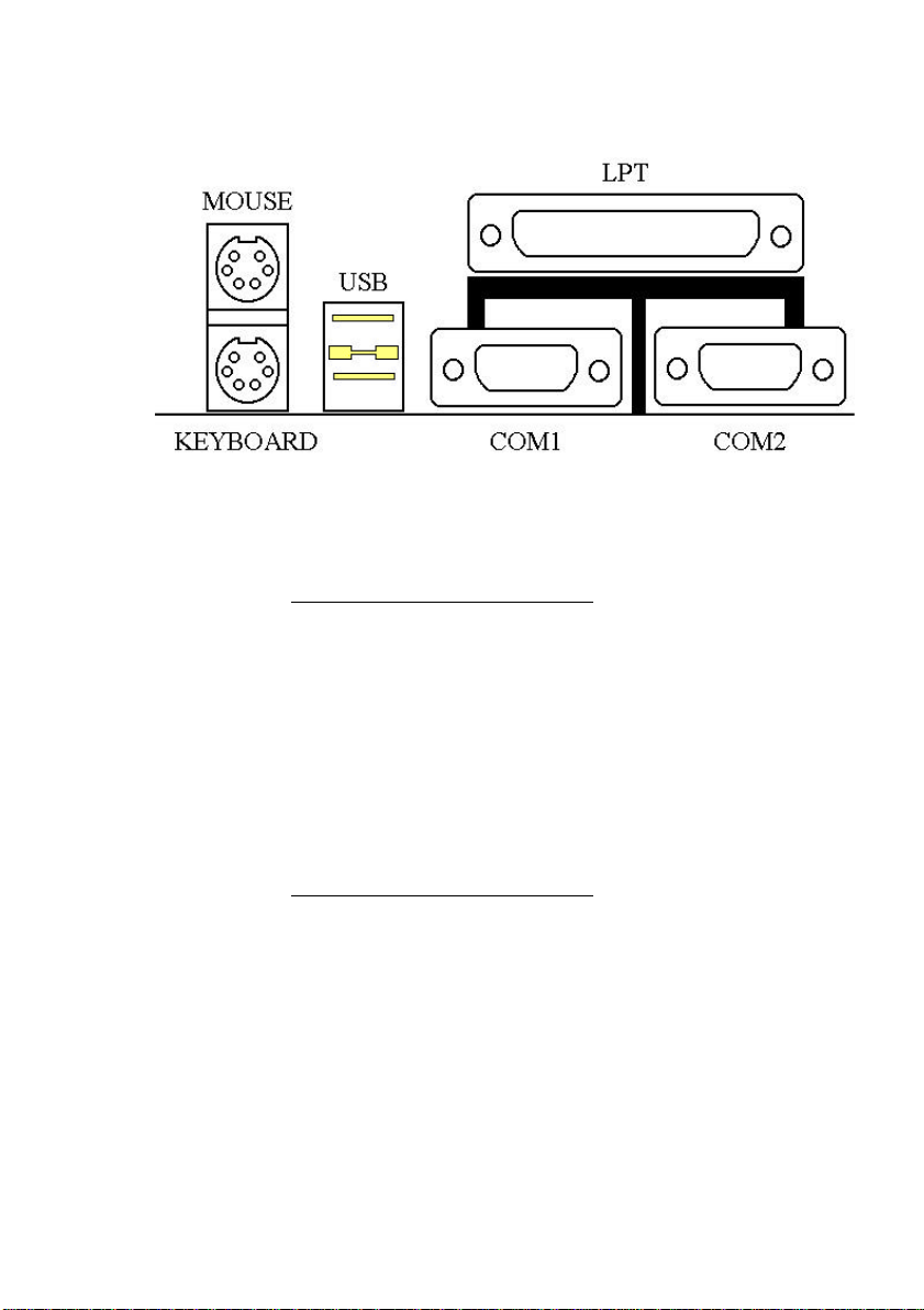
MOUSE - PS/2 Mouse Connector
Attach a PS/2 mouse to this 6-pins Din-connector.
Pin Assignment
1 Mouse data
2 No connection
3 Ground
4 +5VDC
5 Mouse clock
6 No connection
KB - PS/2 Keyboard Connector
Attach a keyboard to this 6-pins Din-connector.
Pin Assignment
1 Keyboard data
2 No connection
3 Ground
4 +5VDC
5 Keyboard clock
6 No connection
Page 10

2-4 Chapter 2
ATX PWR - ATX Power input Connector
Caution: If power supply connectors are not properly attached to ATX
PWR, the power supply or add-on cards may be damaged.
Attach the connectors from the power supply to ATX PWR.
Pin Assignment Pin Assignment
1 +3.3V 11 +3.3V
2 +3.3V 12 -12V
3 Ground 13 Ground
4 +5V 14 ON/OFF control
signal
5 Ground 15 Ground
6 +5V 16 Ground
7 Ground 17 Ground
8 Powergood 18 -5V
9 +5V 19 +5V
10 +12V 20 +5V
FAN1, FAN2 - DC-FAN Power Connector
Pin Assignment
1 Ground
2 +12V
3 Ground
IR - IR Connector(Infrared)
Pin Assignment
1 +5V
2 No connection
3 IR_RX
4 Ground
5 IR_TX
Page 11

Hardware Setup 2-5
I/O port connectors
Name No. of pins Description
IDE1 40 IDE channel 1 connector
IDE2 40 IDE channel 2 connector
FDC 34 Floppy disk connector
LPT 25 Parallel port connector
COM1 9 Serial port COM1 connector
COM2 9 Serial port COM2 connector
USB 8 Universal serial Bus
Notes: *IDE1, IDE2 are high performance PCI IDE connectors. Up to four
IDE interface devices are supported.
Page 12

2-6 Chapter 2
Jumper Switches
You set jumper switches on the mainboard to configure various hardware
options. See Figure 1-1 for jumper locations.
Throughout this section the following symbols are used to indicate jumper
settings.
For 3-pin jumpers, the symbols below are used:
Short Pins 1 and 2 with a jumper cap.
Short Pins 2 and 3 with a jumper cap.
For 2-pins jumpers, the following symbols are used:
Place the jumper cap over the two pins
of the jumper to Short the jumper.
Remove the jumper cap to Open the
jumper cap.
Note: To avoid losing jumper caps, attach the removed jumper cap to one of
the jumper pins.
Page 13

Hardware Setup 2-7
CCMOS - CMOS Discharge Jumper
Jumper CCMOS discharge CMOS memory. When you install the mainboard,
make sure this jumper is set for Normal Operation(1-2). See the jumper as
below.
Setting CCMOS
Normal Operation
(Default)
Discharge CMOS
JR1 - ATX Power Power-On
Low active
High active
(Default)
Setting JR1
Page 14

2-8 Chapter 2
JD1 - DIMM Power Select
Setting JD1
5V
3.3V
(Default)
Installation of CPU
The mainboard is equipped with a CPU-SLOT1 slot to accommodate the KP6
CPU card and Intel PentiumII CPU or above. The default clock rate setting for
KP6 CPU card is 150MHz and PentiumII CPU is 233MHz depend on
autodetect from BIOS. But there is an advantage way for setup menu. The
details please refer the chapter 3 “Award BIOS Setup”.
Page 15

Hardware Setup 2-9
Installation of Memory
The mainboard provides four 72-pin SIMM and two 168-pin DIMM sites for
memory expansion. The SIMM socket supports 1Mx32(4MB), 2Mx32(8MB),
4Mx32(16MB), 8Mx32(32MB), 16Mx32(64MB), and 32Mx32(128MB) single
side or double side SIMM modules. The DIMM socket supports 1Mx64(8MB),
2Mx64(16MB), 4Mx64(32MB), 8Mx64(64MB), 16Mx64(128MB), and
32Mx64(256MB) or double side DIMM modules. Minimum memory size is
8MB and Maximum memory size will be 1GB.
There are four banks of Memory on the system board.
In order to create a memory array certain rules must be followed. The following
set of rules allows for optimum configurations.
l SIMM modules must be populated in pairs; the memory array is 64 or 72
bits wide. (Without parity or with parity)
l Those modules can populated in any order.
l SIMM modules pairs need to populated with the same densities, single or
double. For example, Bank0 must populated with identical densities.
However Bank1 can be populated with different densities than Bank0.
l The asymmetrical DRAM modules should be the same type in the same
bank.
l The EDO DRAM modules can mixed with standard page mode DRAM
module, but must not be in the same bank. For example, Bank0 can be
populated with EDO DRAM module. Each bank will be optimized for that
type of memory according to the BIOS setup.
The following is the valid memory configuration:
Bank Memory Module Total Memory
Bank0
(SIMM1, 2)
Bank1
(SIMM3, 4)
Bank2
(DIMM1)
Bank3
(DIMM2)
4MB, 8MB, 16MB, 32MB,
64MB, 128MB
4MB, 8MB, 16MB, 32MB,
64MB, 128MB
8MB,16MB,32MB,64MB,
128MB, 256MB
8MB,16MB,32MB,64MB,
128MB, 256MB
Total System Memory +)= 8MB ~ 1GB
x2 8MB ~ 256MB
x2 8MB ~ 256MB
x1 8MB ~ 256MB
x1 8MB ~ 256MB
Page 16

2-10 Chapter 2
Page 17

Award BIOS Setup 3-1
Chapter 3 Award BIOS
Setup
All personal computer use a BIOS, or Basic Input / Output system, to provide
control for the hardware functions. When system is powered on or reset, the
CPU is reset and BIOS will do the following:
l Self-test on CPU.
l Verify ROM BIOS checksum.
l Verify CMOS configuration chip.
l Initialize timer.
l Initialize DMA controller.
l Verify system memory and cache memory.
l Install all BIOS function call utilities.
l Verify/initialize all system configurations, like keyboard, floppy drive, hard
disk, initialize EGA or VGA if there is any.
l Hook to the add-in BIOS (include NCR PCI SCSI BIOS) or expansion
BIOS to perform initialization and driver link to the system.
Award’s BIOS ROM has a built-in setup program that allows users to modify
the basic system configuration. This type of information is stored in batterybacked RAM so that the setup information is retained when the power is turned
off. When the system is powered on or reset, the Award BIOS will display a
copyright message on the screen, then the BIOS will perform the system
diagnostics test and initialization. When all of the above tests have been passed,
the message:
“TO ENTER SETUP BEFORE BOOT PRESS CTRL-ALT-ESC
OR DEL KEY”
Page 18

3-2 Chapter 3
is display. If the [Del] key or Ctrl-Alt-Esc is pressed, the screen will be cleared
and then the following message will be shown:
ROM PCI/ISA BIOS (XXXXXXXX)
CMOS SETUP UTILITY
AWARD SOFTWARE, INC.
!! CPU SOFT MENU !!
STANDARD CMOS SETUP
BIOS FEATURES SETUP
CHIPSET FEATURES SETUP
POWER MANAGEMENT SETUP
PCI & ONBOARD I/O SETUP
Esc: Quit
F10: Save & Exit Setup
Description of each function
Figure 3-1 Main Menu
LOAD BIOS DEFAULTS
LOAD SETUP DEFAULTS
PASSWORD SETTING
IDE HDD AUTO DETECTION
SAVE & EXIT SETUP
EXIT WITHOUT SAVING
↓↑→←: Select Item
(Shift)F2: Change Color
Page 19

Award BIOS Setup 3-3
CPU SOFT MENU
The CPU SOFT MENU is for setting CPU parameter. User can change CPU
setting by software easily. In each item press the <F1> key, which will display
the available option.
ROM PCI/ISA BIOS (XXXXXXXX)
!! CPU SOFT MENU !!
Intel Pentium Pro
- Turbo Frequency
AWARD SOFTWARE, INC.
: 150
: Disabled
Esc: Quit
F1: Help
F5: Old Values
F6: Load BIOS Defaults
F7: Load Setup Defaults
Figure 3-2 !! CPU SOFT MENU !!
Intel Pentium Pro Available item as below:
⇒ 150
⇒ 166
⇒ 180
⇒ 200
⇒ ……
◊ Turbo Frequency:
If external clocks support turbo frequency then
screen will display this item.
The meaning of the turbo frequency is external
clock frequency, that can improve the system
performance.
⇒ Disable: CPU external clock is normal
frequency.
⇒ Enable: CPU external clock is turbo
frequency.
Note: Disable turbo mode is recommended.
↑↓→←: Select Item
PU/PD/+/-: Modify
(Shift)F2: Color
Page 20

3-4 Chapter 3
Standard CMOS Setup Menu
The items in Standard CMOS Setup Menu are divided into several categories.
Each category includes none, one, or more than one setup items. Use the arrow
keys to highlight the item and then use the <PgUp> or <PgDn> keys to select
the value you want in each item.
Date (mm:dd:yy) : Wed, Apr 21 1993
Time (hh:mm:ss) : 14:53:31
HARDS DISK Type Size CYLs HEAD PRECOMP LANDZ SECTOR MODE
Primary Master : None 0 0 0 0 0 0 ---------
Primary Slave : None 0 0 0 0 0 0 --------Secondary Master : None 0 0 0 0 0 0 --------Secondary Slave : None 0 0 0 0
Drive A: 1.44M, 3.5 in.
Drive B: None
Floppy 3 Mode Support: Disable Extended Memory: 3328K
Video : EGA/VGA Other Memory: 128K
Halt On: All, But Keyboard Total Memory: 4096K
Base Memory: 640K
Expanded Memory: 0K
Esc: Quit
F1: Help
↓↑→←: Select Item
(Shift)F2: Change Color
PU/PD/+/-: Modify
F3: Toggle Calendar
Figure 3-3 Standard CMOS Setup Menu
The setup program is completely menu-driven:
1. Use arrow keys to select entry of Data, Time, Hard Disk, Floppy, Display,
and Keyboard.
2. Use PgUp/PgDn key to modify the options of each entry.
3. Use Esc to exit.
Hard Disk size selection
The Award BIOS supports three HDD modes: NORMAL, LBA and LARGE.
NORMAL mode: The maximum HDD size supported by the NORMAL
mode is 528 Megabytes.
Page 21

Award BIOS Setup 3-5
LBA mode: Logical Block Addressing mode is a new HDD accessing method
designed to overcome the 528Megabytes limitation. The number
of cylinders, heads, and sectors shown in setup may not be the
number physically contained in the HDD. During HDD
accessing the IDE controller will transform the logical address
described by cylinder, head, and sector number into its own
physical address inside the HDD. The maximum HDD size
supported by the LBA mode is 8.4Gigabytes.
LARGE mode: Some IDE HDDs contain more than 1024 cylinders without
LBA supports. This access mode tricks DOS (or other OS)
that the number of cylinders is less than 1024 by dividing it
by 2. At the same time, the number of heads is Multiplied by
2. The maximum HDD size supported by LARGE mode is 1
Gigabytes.
Floppy 3 mode support
This is the Japanese standard floppy drive. The standard stores 1.2MB in a 3.5”
diskette.
Page 22

3-6 Chapter 3
BIOS Features Setup Menu
The BIOS Features setup program is equipped with a series of help screens
accessed by the <F1> key, which will display the available options for a
particular configuration feature and special help for some of the options. If you
don’t really understand the meanings of each item, please don’t change the
following default values.
ROM PCI/ISA BIOS (XXXXXXXX)
BIOS FEATURES SETUP
AWARD SOFTWARE, INC.
Virus Warning
CPU Internal Cache
External Cache
Quick Power on Self Test
Boot Sequence
Swap Floppy Drive
Boot Up Floppy Seek
Boot Up Numlock Status
IDE HDD Block Mode
Typematic Rate Setting
Typematic Rate (Chars/Sec)
Typematic Delay (Msec)
Security Option
PCI/VGA Palette Snoop
: Disabled
: Enabled
: Enabled
: Enabled
: A, C
: Disabled
: Disabled
: On
: Enabled
: Enabled
: 30
: 250
: Setup
: Disabled
Video BIOS shadow
C8000-CBFFF Shadow
CC000-CFFFF Shadow
D0000-D3FFF Shadow
D40000D7FFF Shadow
D8000-DBFFF Shadow
DC000-DFFFF Shadow
Esc: Quit
F1: Help
F5: Old Values
F6: Load BIOS Defaults
F7: Load Setup Defaults
Figure 3-4 BIOS Feature Setup
: Enabled
: Disabled
: Disabled
: Disabled
: Disabled
: Disabled
: Disabled
↑↓→←: Select Item
PU/PD/+/-: Modify
(Shift)F2: Color
A short description of screen items follows:
Virus Warning Enable this option and a warning message appears when
there is any attempt to access the boot sector or hard disk
partition table.
CPU Internal This option enables/disables the CPU’s internal cache.
Cache (The Default setting is Enabled.)
External Cache This option enables/disables the external cache memory.
(The Default setting is Enabled.)
Quick Power Enabled provides a fast POST at boot-up.
On Self Test
Boot Sequence The system can be boot from drive A:, or C:. There are
two sequences can be choose: “A, C”, “C, A”.
Page 23

Award BIOS Setup 3-7
Swap Floppy Enabled changes the sequence of the A: and B: drives.
Drive (The Default setting is Disabled.)
Boot Up Floppy Enable this item and the BIOS searches for installed
Seek floppy disk drives to determine if they are 40 tracks
(360K drive) or 80 tracks (720K, 1.2M, 1.44M, or
2.88M drives). Disable this item and the BIOS does not
search for floppy drive type by track number.
IDE HDD Block This option enables/disables the IDE HDD Block Mode
Mode function. Older HDDs do not support this function. (The
Default setting is Enabled.)
Typematic Rate Enable this option to adjust the keystroke repeat rate.
Setting
Typematic Rate Choose the rate a Character keeps repeating.
(Chars/Sec)
Typematic Delay Choose how long after you press a key that a character
(Msec) begins repeating.
Security Option Choose Setup or System. Use this feature to prevent
unauthorized system boot-up or use of BIOS Setup.
“System” - Each time the system is booted the password
prompt appears.
“Setup” - If a password is set, the password prompt only
appears if you attempt to enter the Setup program.
PCI/VGA Palette Choose Enable or Disable. Used to alter VGA palette
Snoop setting while graphics pass through feature connector of
PCI VGA card and processed by MPEG card.
Video or BIOS shadow copies BIOS code from slower ROM to
Adapter BIOS faster RAM. BIOS can then execute from RAM.
Shadow
Page 24

3-8 Chapter 3
Chipset Features Setup Menu
The Chipset Features Setup Menu are used to change the parameter of the
chipset internal registers. All of these parameters are hardware dependent. A
wrong parameters may be caused the mainboard out of order.
Run the Chipset Features Setup as follows.
1. Choose “CHIPSET FEATURES SETUP” from the Main Menu and
following screen appears.
ROM PCI/ISA BIOS (XXXXXXXX)
CHIPSET FEATURES SETUP
AWARD SOFTWARE, INC.
Auto Configuration
DRAM Speed Selection
DRAM RAS# Precharge Time
MA Additional Wait State
RAS# to CAS# Delay
DRAM Read Burst (B/E/F)
DRAM Write Burst (B/E/F)
ISA Bus Clock
: Enabled
: 60 ns
:4
: Enabled
: Enabled
: x2/2/3
: x3/3/3
: PCICLK/3
8 Bit I/O Recovery Time
16 Bit I/O Recovery Time
Memory Hole At 15M-16M
DRAM Fast Leadoff
Passive Release
Delayed Transaction
: 1
: 1
: Disabled
: Disabled
: Enabled
: Disabled
DRAM Refresh Queue
DRAM RAS Only Refresh
DRAM ECC/PARITY Select
Fast Dram Refresh
Read-Around-Write Combine
PCI Burst Write Combine
PCI-To-DRAM Pipeline
CPU-To-PCI Write Post
CPU-To-PCI IDE Posting
System BIOS Cacheable
Video RAM Cacheable
: Enabled
: Disabled
: Disabled
: Disabled
: Enabled
: Enabled
: Enabled
: Enabled
: Enabled
: Disabled
: Disabled
Esc: Quit
F1: Help
F5: Old Values
F6: Load BIOS Defaults
F7: Load Setup Defaults
↑↓→←: Select Item
PU/PD/+/-: Modify
(Shift)F2: Color
Figure 3-5 Chipset Feature Setup Menu
Note:
Memory Hole At Choose Enable or Disable (Default). Used to reserved
15M-16M memory addressing space for some special add-on-card
that requires 1M bytes addressing space from 15 to
16M.
2. Use the arrow keys to move between items and select values. Modify
selected fields using the PgUp/PgDn/+/- keys.
3. After you have finished with the Chipset Features Setup, press the <Esc>
key and follow the screen instructions to save or disregard your new
settings.
Page 25

Award BIOS Setup 3-9
Power Management Setup
The Power Management Setup option lets you set the system’s power saving
functions.
1. Choose “POWER MANAGEMENT SETUP” from the Main Menu.
ROM PCI/ISA BIOS (XXXXXXXX)
POWER MANAGEMENT SETUP
AWARD SOFTWARE, INC.
Power Management : User Define ** Power Down & Resume Events **
PM Control by APM
Video Off Method
Video Off Option
Modem Use IRQ
Doze Mode
Standby Mode
Suspend Mode
HDD Power Down
** Wake Up Events In Doze & Standby ** IRQ 13 (Coprocessor) :ON
IRQ 3 (Wake-Up Event)
IRQ 4 (Wake-Up Event)
IRQ 8 (Wake-Up Event)
IRQ12 (Wake-Up Event) : ON Esc: Quit
Figure 3-6 Power Management Setup Menu
: Yes
: V/H SYNC + Blank
: Susp, stby à off
: NA
: Disable
: Disable
: Disable
: Disable
: ON
: ON
: OFF
IRQ 3 (COM2)
IRQ 4 (COM1)
IRQ 5 (LPT2)
IRQ 6 (Floppy Disk)
IRQ 7 (LPT 1)
IRQ 8 (RTC Alarm)
IRQ 9 (IRQ2 Redir)
IRQ 10 (Reserved)
IRQ 11 (Reserved)
IRQ 12 (PS/2 Mouse)
IRQ 14 (IDE-1)
IRQ 15 (IDE-2)
F1: Help
F5: Old Values
F6: Load BIOS Defaults
F7: Load Setup Defaults
: ON
: ON
: ON
: ON
: ON
: OFF
: ON
: ON
: ON
: ON
: ON
: ON
↑↓→←: Select Item
PU/PD/+/-: Modify
(Shift)F2: Color
2. Use the arrow keys to move between items and to select values. Modify the
selected fields using the PgUp/PgDn/+/- keys.
A short description of selected screen items follows:
Power Options are as follows:
Management
User Define Set the power saving options by user.
(Default)
Disabled Disables the Green PC Features.
Min Saving Doze = 1Hour
Standby = 1Hour
Suspend = 1Hour
Max Saving Doze = 1Min
Standby = 1Min
Suspend = 1Min
Page 26

3-10 Chapter 3
PM Control by Choose No or Yes (Default). APM stands for Advanced
APM Power Management. “Yes” makes your power
management more flexible.
Video Off Method Choose DPMS, Blank screen, or V/H Sync + Blank
(Default). With this item V/H SYNC is controlled by
software. If you have a VGA card that is not compatible
with the default option, switch to “Blank screen”, even
though it consumes more power than “V/H SYNC +
Blank”. If your VGA card and VGA monitor support
VESA DPMS, switch the option to “DMPS”.
Video Off Option Choose “Always On”, “All Modes Off” (Suspend,
Standby and Doze mode), “Susp, Stby Off”(Default)
and “Suspend Off”. This item shuts the video off
when entering Doze mode, Standby mode or Suspend
mode.
Modem Use IRQ Setting “Modem Use IRQ” for the APM modem ring
wake up function.
HDD Power Down Choose a time interval from 1 to 15 minutes or
“Disabled” (Default). When the set time has elapsed, the
BIOS sends a command to the HDD to enter idle (sleep)
mode, turning off the motor. This function is only valid
for IDE HDDs that support power saving function.
Doze Mode The default setting is Disabled. When the Power
Management item is switched to “User Define” you can
select a time interval from 1minute to 1 hour. When the
set time elapses without activity the system enters Doze
mode.
If the idle time for all PM events IRQ 3-15 Activity
is greater than the Doze mode, and the CPU speed
slows down. If the Video Off Option is set to “All Modes
Off”, the screen shuts off.
Standby Mode The default setting is Disabled. When the Power
Management item is switched to “User Define” you can
select a time interval from 1 minute to 1 hour. When the
set time elapses without activity the system enters
Standby mode.
Page 27

Award BIOS Setup 3-11
If the idle time for all PM events is greater than the
Standby time you set the system will enter Standby mode,
and the CPU speed slows down. If the screen will shut
off.
Suspend Mode The default setting is Disabled. When the Power
Management item is switched to “User Define” you can
select a time interval from 1 minute to 1 hour. When the
set time elapses without activity the system enters
Suspend mode.
If the idle time for all PM events is greater than the
Suspend time you set the system will enter Suspend
mode, and the CPU Internal frequency drops to 0 MHz.
If the “Video Off Option” is set to “Suspend Off”, the
screen will shut off.
Wake-up Event “ON” - Wake up the system when IRQn signal received
in the Doze & Standby mode.
“OFF” - IRQn signal does not wake up the system, when
the system is in the Doze & Standby mode.
Power Down & There are several Power Management events can be
Resume Events selected IRQ3-15 Activity.
“ON” - Reset green timer whenever PM Events Activity.
“OFF - Discard any PM Events Activity and
continuously accumulate timer count down for green
function.
3. After you have finished with the Power Management Setup, press the
<Esc> key to return to the Main Menu.
Page 28

3-12 Chapter 3
PCI & Onboard I/O Setup
The PCI & Onboard I/O Setup option lets you assign INT#s, IRQs, I/O ports,
and other hardware settings to the mainboard’s PCI slots and onboard I/O.
ROM PCI/ISA BIOS (XXXXXXXX)
POWER MANAGEMENT SETUP
AWARD SOFTWARE, INC.
Reset PnP Config Data
PCI IRQ Actived By
BIOS Auto-Config PCI IRQ
- 1st Available IRQ
- 2nd Available IRQ
- 3rd Available IRQ
- 4th Available IRQ
PCI IDE Card 2nd Channel
PCI IDE Card IRQ Map to
-Primary IDE INT#
- Secondary IDE INT#
: Disabled
: Level
: Disabled
: 10
: 11
: 9
: 5
: Enable
: PCI-AUTO
: A
: B
Onboard FDD Controller
Onboard Serial Port 1
Onboard Serial Port 2
- Onboard IR Function
- IR Duplex Mode
Onboard Parallel Port
- Parallel Port Mode
- ECP Mode Use DMA
: Enabled
: 3F8/IRQ4
: 2F8/IRQ3
: IrDA
: Half
: 378/IRQ7
: ECP+EPP1.9
: 3
Onboard USB Controller
Onboard IDE-1 Controller
- Master Drive PIO Mode
- Slave Drive PIO Mode
Onboard IDE-2 Controller
- Master Drive PIO mode
- Slave Drive PIO mode
: Disabled
: Enabled
: Auto
: Auto
: Enabled
: Auto
: Auto
Esc: Quit
F1: Help
F5: Old Values
F6: Load BIOS Defaults
F7: Load Setup Defaults
↑↓→←: Select Item
PU/PD/+/-: Modify
(Shift)F2: Color
Figure 3-7 PCI Configuration Setup Menu
Reset PnP Config If you want to clear ESCD data next time you boot up,
Data and ask the BIOS to reset the settings for the Plug &
Play ISA Card and PCI Card, select “Enabled”. But the
next time you boot up, this option will automatically be
set as “Disabled”.
PCI PnP BIOS Choose Enabled (Default) or Disabled. If Enabled the
Auto-Config BIOS will automatically assigns IRQ to the PCI INT#. If
Disabled the PCI INT# will be assigned by the next
setup item - “Xth Available IRQ”.
Xth Available IRQ These categories select a IRQ for INT#. There are ten
IRQs options (3, 4, 5, 7, 9, 10, 11, 12, 14, 15) for
available IRQs.
1st Available IRQ means BIOS will assign this IRQ to
first INT found on the PCI slots (the assignment
sequence is slot1, 2, 3).
Page 29

Award BIOS Setup 3-13
PCI IDE Card 2nd Choose Disable or Enable (Default). If the 2nd channel
Channel is not used on the PCI IDE card, switch the option to
“Disable”. Or IRQ15 can not work on the ISA slots.
PCI IDE Card PCI-Auto:
IRQ Map to If the BIOS can detect PCI IDE on one of the PCI slots,
then the appropriate INT# will be auto-assigned to
IRQ14.
PCI-slotX:
If the BIOS can not detect a PCI IDE card, (because the
PCI IDE card does not support this function) the user
needs to manually select the PCI-slot occupied by the
PCI IDE card.
Primary IDE INT#, Secondary IDE INT#:
If the IDE card supports 2 IDE channels, the BIOS needs
to assign 2 INT channels for the IDE card. (Don’t select
same INT#)
ISA:
This setting assigns no IRQs to the PCI slots. Use this
setting with PCI IDE cards that connect IRQ14 and
IRQ15 directly from an ISA slot using a cable from a
legacy paddle board.
Note: M/B PCI Slot INT# hardware is designed as below:
“Slot1-INT#A”, “Slot2-INT#B”, and “Slot3-INT#C” are assigned to the
same IRQ. (Do not use them at the same time.)
“Slot1-INT#B”, “Slot2-INT#C”, and “Slot3-INT#D” are assigned to the
same IRQ. (Do not use them at the same time.)
“Slot1-INT#C”, “Slot2-INT#D”, and “Slot3-INT#A” are assigned to the
same IRQ. (Do not use them at the same time.)
“Slot1-INT#D”, “Slot2-INT#A”, and “Slot3-INT#B” are assigned to the
same IRQ. (Do not use them at the same time.)
Onboard FDD This option enables or disables the on-board floppy disk
Controller controller.
Onboard Serial Choose Disable, 3F8h/IRQ4, 2F8h/IRQ3, 3E8h/IRQ4,
Port X 2E8h/IRQ3 to set the on-board serial ports. But don’t
choose duplicate I/O port and IRQ.
Serial Port 2 Use This option enables/disables the IR function in on-board
IR serial port 2 and selects IR mode HPSIR(IrDA) or
ASKIR(Amplitude Shift Keyed IR).
Page 30

3-14 Chapter 3
IR Duplex Mode IR duplex mode Half(Default) or Full selection.
Onboard Parallel Choose Disable, 3BCh/IRQ7, 278h/IRQ5, or 378h/IRQ7
Port (Default) to set the on-board parallel port.
Parallel Port Choose EPP1.7, EPP1.9, ECP, ECP + EPP1.7, ECP +
Mode EPP1.9, PS/2, or Normal (Default) mode.
ECP Mode Use Choose DMA channel 1 or channel 3 to set the ECP
DMA mode.
Onboard IDE This option enables or disables the one board PCI IDE
Controller controller.
Onboard IDE PIO Choose Mode 0 ~ Mode 4, or Auto (Default) to change
Mode IDE data transfers speed.
Load BIOS Defaults
BIOS Defaults indicates the values required by the system for the minimum
performance. Choose this item and following message appears:
“Load BIOS Defaults (Y/N)? N”
To use the BIOS defaults, change the prompt to “Y” and press <Enter>.
Load Setup Defaults
Setup Defaults indicates the values of system parameters which will give the
best performance. Choose this item and the following message appears:
“Load Setup Defaults (Y/N)? N”
To use the Setup defaults, change the prompt to “Y” and press <Enter>.
Page 31

Award BIOS Setup 3-15
Setting Password
This Main Menu item lets you configure the system so that a password is
required every time the system boots or an attempt is made to enter the Setup
program. Change the password as follows:
1. Choose “PASSWORD SETTING” in the Main Menu and press <Enter>.
The following message appears:
“Enter Password:”
2. Enter a password and press <Enter>.
(If you do not wish to use the password function, you can just press <Enter>
and a “Password disabled” message appears.)
3. After you enter your password, the following message appears prompting
you to confirm the new password:
“Confirm Password:”
4. Re-enter your password and then Press <ESC> to exit to the Main Menu.
Important: If you forget or lose the password, the only way to access the
system is to set the CMOS RAM discharge jumper to clear the
CMOS RAM. All setup information is lost and you must run the
BIOS setup program again.
IDE HDD Auto Detection
The BIOS automatically detects the hard disk type and configures the
STANDARD CMOS SETUP accordingly.
Page 32

3-16 Chapter 3
Standard types of hard disks
Type Size Cylinders Heads W-Pcomp L-Zone Sect
1 10MB 306 4 128 305 17
2 20MB 615 4 300 615 17
3 30MB 615 6 300 615 17
4 62MB 940 8 512 940 17
5 49MB 940 6 512 940 17
6 21MB 615 4 65535 615 17
7 32MB 462 8 256 511 17
8 31MB 733 5 65535 733 17
9 117MB 900 15 65535 901 17
10 20MB 820 3 65535 820 17
11 35MB 855 5 65535 855 17
12 49MB 855 7 65535 855 17
13 20MB 306 8 128 319 17
14 42MB 733 7 65535 733 17
16 20MB 612 4 0000 663 17
17 40MB 977 5 300 977 17
18 56MB 977 7 65535 977 17
19 59MB 1024 7 512 1023 17
20 30MB 733 5 300 732 17
21 42MB 733 7 300 732 17
22 30MB 733 5 300 733 17
23 10MB 306 4 0000 336 17
24 53MB 925 7 0000 925 17
25 69MB 925 9 65535 925 17
26 43MB 754 7 754 754 17
27 68MB 754 11 65535 754 17
28 40MB 699 7 256 699 17
29 68MB 823 10 65535 823 17
30 53MB 918 7 918 918 17
31 93MB 1024 11 65535 1024 17
32 127MB 1024 15 65535 1024 17
33 42MB 1024 5 1024 1024 17
34 10MB 612 2 128 612 17
35 76MB 1024 9 65535 1024 17
36 68MB 1024 8 512 1024 17
37 40MB 615 8 128 615 17
38 24MB 987 3 987 987 17
39 57MB 987 7 987 987 17
40 40MB 820 6 820 820 17
41 40MB 977 5 977 977 17
42 40MB 981 5 981 981 17
43 48MB 830 7 512 830 17
44 68MB 830 10 65535 830 17
45 114MB 917 15 65535 918 17
46 152MB 1224 15 65535 1223 17
Page 33

Bus Master IDE Driver 4-1
Chapter 4 Bus Master IDE
Driver
The Intel PIIX3 Bus Master IDE is now include in the mainboard.
OS Support: Windows 95, Windows NT 3.5/3.51/4.0, OS/2 V2.x & Warp
3.0
Installation: Each OS has different install procedure, please check
README.TXT file under each OS’s directory.
Page 34

4-2 Chapter 4
 Loading...