

Page 1
NEW
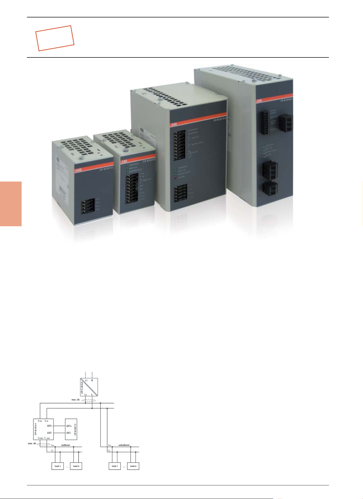
Ultra capacitor based buffer modules
CP-B range
4
Power supply systems have to be highly reliable in most areas of
energy management and automation technology.
Often batteries are used for supporting the supply system in
case of mains failures. Batteries have limited lifetimes depending on environmental parameters and have to be maintained
regularly, which causes efforts and costs.
Using the latest ultra-capacitor technology, ABB offers an innovative and completely maintenance free new product for
buffering the 24 V DC supply in case of interrupted mains on the
primary side of the switch mode power supply.
The CP-B range is an ultra-capacitor buffer energy storage for
power supply units which ensures a short term uninterrupted
power supply system. In case of a power loss, the energy stored
in the capacitor guarantees that the load is continually provided
up to several hundred seconds depending on the load current.
Application example
Characteristics
• 3 buffer modules for buffering 24 V DC:
CP-B 24/3.0 (3 A / 1 kWs1))
CP-B 24/10.0 (10 A / 10 kWs1))
CP-B 24/20.0 (20 A / 8 kWs1))
• CP-B 24/3.0 and CP-B 24/20.0 expandable with
additional extension module(s) CP-B EXT.2 (2 kWs1))
• LEDs for status indication
• Relay contacts for status messaging
• Very high backup times (e.g. with CP-B 24/10.0 up to 8 min-
utes at 1 A load current)
• Short charging times
• High efficiency, higher than 90%
• Wide temperature range
• DIN rail mountable, compact enclosures
• Advantages in comparison to battery buffers
• Maintenance free
• No deep discharge
• Temperature resistant
• A approval (UL508, CSA22.2 No 14)
1)
internal energy buffer; 2) pending
²)
4/46
2CDC110004C0207
Page 2
Ultra capacitor based buffer modules
NEW
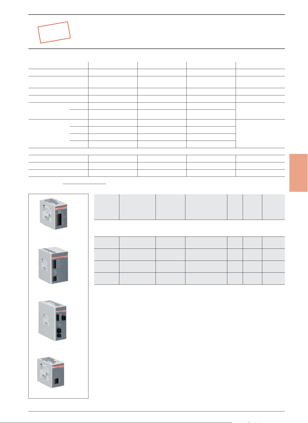
Product selection table
Order code 1SVR427060R0300 1SVR427060R1000 1SVR427060R2000 1SVR427065R0000
Rated input
voltage
Rated current 3 A DC 10 A DC 20 A DC –
Energy storage (min.) 1.000 Ws 10.000 Ws 8.000 Ws 2.000 Ws
Typical charging
time at load current
Typical buffer
1)
time
at load cur-
rent
Dimensions
Width 60.00 mm 127.00 mm 84.00 mm 60.00 mm
Height 92.50 mm 163.00 mm 192.00 mm 92.50 mm
Depth 116.00 mm 150.00 mm 198.00 mm 116.00 mm
1)
buffering time =
100 % 65 s 120 s 68 s
0 % 56 s 82 s 62 s
100 % 14 s 40 s 15 s
50 % 28 s 80 s 30 s
25 % 74 s 140 s 60 s
10 % 148 s 380 s 150 s
energy storage x 0.9
current x output voltage
CP-B range
CP-B 24/3.0 CP-B 24/10.0 CP-B 24/20.0 CP-B EXT.2
24 V DC 24 V DC 24 V DC –
4
CP-B 24/3.0
CP-B 24/10.0
CP-B 24/20.0
Type
2CDC 271 001 S00102CDC 271 002 S00102CDC 271 003 S00102CDC 271 004 S0010
CP-B range
CP-B
24/3.0
CP-B
24/10.0
CP-B
24/20.0
CP-B
EXT.2
Rated
input voltage
24 V DC 3 A DC
24 V DC 10 A DC
24 V DC 20 A DC
––
Rated
current
Order code
1SVR 427 060 R0300
1SVR 427 060 R1000
1SVR 427 060 R2000
1SVR 427 065 R0000
Pack.
unit
pieces
1 0.55 / 1.21
1 2.10 / 4.63
1 2.20 / 4.85
1 1.00 / 2.21
Price
1 piece
Weight
1 piece
kg / Ib
CP-B EXT.2
4/47
2CDC110004C0207
Page 3
4
NEW
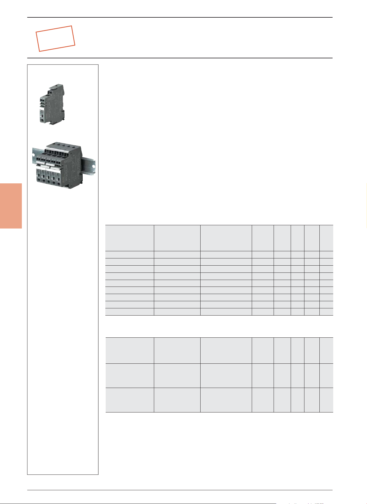
Electronic Protection Devices
EPD24-TB-101
for use behind 24 V DC Switch Mode
Power Supplies
The protection devices EPD24 extend the ABB product range of modular DIN rail components by
electronic overcurrent protection modules for selective protection of 24V DC load circuits.
This protection is achieved by a combination of active electronic current limitation in the case of a short
circuit and an overload deactivation from 1.1 x I
If a fault occurs in a load circuit, the protection device EPD24 will detect this rapidly and reliably, disable
the power output transistor and hence interrupt the current flow in the defective circuit. The maximum
possible overcurrent is always limited to 1.5…1.8 times the selected rated current. An activation of
capacitive loads up to 20,000 μF is possible, deactivation only occurring in the case of overloads or
short circuits. Selective deactivation of the defective current circuit means undefined error states and a
complete system stop are prevented.
Features
• Selective load protection one, electronic trip characteristics.
• Active current limitation for safe connection of capacitive loads up to 20,000 μF and on overload/short
circuit.
• Current ratings 0.5 A...12 A.
• Reliable overload disconnection with 1.1 x I
• Manual ON/OFF button
• Clear status and failure indication through LED and auxiliary contact.
• Integral fail-safe element adjusted to current rating.
• Width per unit only 12.5 mm.
• Rail mounting
• Ease of wiring through busbar LINE+ and 0 V as well as signal bars.
• UL- and CSA-approvals allow international use of the devices.
upwards.
n
N
Selection table
Rated
current I
in A
Selection table accessories
1) Max. load with one line entry I
n
0.5
1
2
3
4
6
8
10
12
Busbars for LINE+
and 0 V,
grey insulation,
length 500 mm
Signal Bars
for aux. contacts,
grey insulation,
length 21 mm
Max. load with two line entries I
Order details
Type code
EPD24-TB-101-0.5A
EPD24-TB-101-1A
EPD24-TB-101-2A
EPD24-TB-101-3A
EPD24-TB-101-4A
EPD24-TB-101-6A
EPD24-TB-101-8A
EPD24-TB-101-10A
EPD24-TB-101-12A
Order details
Type code
EPD-BB500
1)
EPD-SB21
Order code
2CDE 601 101 R2905
2CDE 601 101 R2001
2CDE 601 101 R2002
2CDE 601 101 R2003
2CDE 601 101 R2004
2CDE 601 101 R2006
2CDE 601 101 R2008
2CDE 601 101 R2010
2CDE 601 101 R2012
Order code
2CDE 605 100 R0500
2CDE 605 200 R0021
= 50 A (recommended: center-feeding)
max
= 63 A
max
bbn
40 16779
EAN
829960
829984
830003
830027
830041
830065
830089
830102
830126
bbn
40 16779
EAN
830140
830164
Price
1 piece
Price
1 piece
Price
group
Price
group
Weight
Pack
1
unit
piece
pc.
kg
0.065 4
0.065 4
0.065 4
0.065 4
0.065 4
0.065 4
0.065 4
0.065 4
0.065 4
Weight
Pack
1
unit
piece
pc.
kg
0.20 10
0.04 10
4/50
2CDC110004C0207
Page 4

Electronic Protection Devices
EPD24-TB-101
NEW
Wiring diagramm
EPD24-TB-101
without signal input
with signal output F
(single signal, NO)
Operating condition: 13-14 closed
Fault condition: 13-14 open
LINE+ 1
14
13
LOAD+
2
0V
3
Technical data (T
= 25 °C, UB = 24 V DC)
amb.
for use behind 24 V DC Switch Mode Power Supplies
Operating data
Start
:
B
:
0
K
24 V DC (18...32 V)
fi xed current ratings:
0.5, 1, 2, 3, 4, 6, 8, 10, 12 A
ON condition: typically 20...30 mA
depending on signal output
– multicolour LED:
Green: – unit is ON (S1 = ON)
– load circuit / Power-MOSFET
is switched on
Orange: – in the event of overload or short circuit until
Red: – unit electronically disconnected
– load circuit/Power-MOSFET OFF
– undervoltage (U
– after switch-on till the end of the delay period
OFF: – manually switched off (S1 = OFF)
or device is dead
– potential-free auxiliary contact F
– ON/OFF/ condition of switch S1
Power-MOSFET switching output
(high slide switch)
typically 1.1 x I
active current limitation (see table 1)
see time/current characteristics
typically 3 s at I
typically 100 ms...3 s at I
(or 1.5 x IN/1.3 x IN, )
internal temperature monitoring with electronic disconnection
with hysteresis, no reset required:
load »OFF« at U
typically 0.5 sec after every switch-on and after applying US
electronic disconnection
suitable external free-wheeling circuit to be used
with inductive load
potential-free auxiliary contact
max. 30 V DC/0.5 A, min. 10 V DC/10 mA
voltage U
no overload, no short circuit
– device switched off (switch S1 is in OFF position)
– no voltage U
overload condition > 1.1 x IN up to electronic disconnection
– electronic disconnection upon overload or short circuit
– Device switched off with control signal
(switch S1 is in ON position)
single signal, make contact
contact open, terminal 13-14
signal output fault conditions
– no operating voltage U
– ON/OFF switch S1 is in OFF position
– red LED lighted (electronic disconnection)
electronic disconnection
< 8 V)
B
(1.05...1.35 x IN)
N
> 1.1 x IN
Load
< 8 V
B
applied, switch S1 is in ON position
B
applied
B
> 1.8 x IN
Load
B
Operating voltage U
Current rating IN:
Closed current I
Staus indication
by means of:
Load circuit
Load output
Overload disconnection
Short-circuit current I
Trip time
For electronic
disconnection
Temperature disconnection
Low voltage monitoring
load output
Starting delay t
Disconnection of
load circuit
Free-wheeling circuit
Several load outputs must not be connected in parallel
Signal output
Electrical data
ON condition LED green
OFF condition LED off
Fault condition LED orange
Fault condition LED red
Aux. contact
Fault
4
4/51
2CDC110004C0207
Page 5

Electronic Protection Devices
EPD24-TB-101
4
NEW
Technical data (T
= 25 °C, UB = 24 V DC)
amb.
for use behind 24 V DC Switch Mode Power Supplies
General data
Fail-Safe element
Housing material
Mounting
Ambient temperature
Storage temperature
Humidity
Vibration
Degree of protection
EMC
(EMC directive, CE logo)
Isolations coordination
(IEC 60934)
Dielectric strength
Isolation resistance (OFF condition)
Approvals/Declarations of conformity
Dimensions (B x H x T)
Weight
Terminals Line+/LOAD+/0V
Screw terminals
Max. cable cross section fl exible with wire end ferrule w/wo plastic
sleeve
Multi-lead connection (2 identical cables) rigid/fl exible
Flexible with wire end ferrule without plastic sleeve
Flexible with TWIN wire end ferrule with plastic sleeve
Wire stripping length
Tightening torque (EN 60934)
Terminals aux. contacts
Screw terminals
Max. cable cross section fl exible
with wire end ferrule w/wo plastic sleeve
Wire stripping length
Tightening torque (EN 60934)
Table 1: voltage drop, current limitation, max. load current
current rating typically voltage drop active current max. load current at 100 % ON duty
I
N
0.5 A 70 mV 1.8 x I
1 A 80 mV 1.8 x I
2 A 130 mV 1.8 x I
3 A 80 mV 1.8 x I
4 A 100 mV 1.8 x I
6 A 130 mV 1.8 x I
8 A 120 mV 1.5 x I
10 A 150 mV 1.5 x I
12 A 180 mV 1.3 x I
Attention: when mounted side-by-side without convection the ERD24 should not carry more than 80 % of its rated load with 100% ON duty due to thermal effects.
UON at I
N
limitation (typically) T
N
N
N
N
N
N
N
N
N
backup fuse for EPD24 not required
because of the integral redundant fail-safe element
moulded
symmetrical rail to EN 50022-35x7.5
0...+50 °C (without condensation, see EN 60204-1)
-20...+70 °C
96 hrs/95 % RH/40 °C to IEC 60068-2-78, test Cab.
climate class 3K3 to EN 60721
3 g, test to IEC 60068-2-6 test Fc
housing: IP20 DIN 40050
terminals: IP20 DIN 40050
emission: EN 61000-6-3
susceptibility: EN 61000-6-2
0.5 kV/pollution degree 2
reinforced insulation in operating area
max. 32 V DC (load circuit)
n/a, only electronic disconnection
UL 2367 Solid State Overcurrent Protectors
UL 1604, (class I, division 2, groups A, B, C, D)
UL 508
CSA C22.2 No. 213 (class I, division 2)
CSA C22.2 No. 142
CE logo
12.5 x 80 x 83 mm
approx. 65 g
M4
2
0.5 – 10 mm
0.5 – 4 mm
0.5 – 2.5 mm
0.5 – 6 mm2
10 mm
1.5 – 1.8 Nm
M3
0.25 - 2.5 mm2
8 mm
0.5 Nm
2
2
= 40 °C T
ambient
0.5 A 0.5 A
1 A 1 A
2 A 2 A
3 A 3 A
4 A 4 A
6 A 5 A
8 A 7 A
10 A 9 A
12 A 10.8 A
ambient
= 40 °C
4/52
2CDC110004C0207
Page 6

K
NEW
Technical details
EPD 24-TB-101
Tripping curve and max. cable lengths
Protection
Time/Current characteristic curve (TU = 25 °C)
– The trip time is typically 3 s in the range between 1.1 and 1.8 x I
1)
– Electronic current limitation occurs at typically 1.8 x I
which means that under all overload conditions (independent of the power supply
N
and the resistance of the load circuit) the max. overload before disconnection will not exceed 1.8 x I
1)
.
N
1)
times
N
the current rating. Trip time is between 100 ms and 3 sec (depending on overload or at short circuit).
– Without this current limitation a considerably higher overload current would flow in the event of an overload or short circuit.
devices
10000
1000
100
10
5
1
trip time in seconds
0.1
0.01
0
disconnection
typically 1.1 x I
1
1)
1.8 x I
N
N
current limitation
typically 1.8 x I
2
1)
N
3
...times rated current
4
5
I
1)
Current limitation typically 1.8 x IN at IN = 0.5 A...6 A
Current limitation typically 1.5 x I
Current limitation typically 1.3 x I
Maximum cable lenghts
EPD24 reliably trips from 0 Ω up to max. circuit resistance R
Calculation of R
max
Selected rating IN (A)
Operating voltage U
Trip current I
(Ω) = (UB/Iab) -0.050 5.07 2.51
R
max
2)
Voltage drop of EPD24 and tolerance of trip point (typically 1.1 x IN = 1.05 ... 1.35 x IN) have been taken into account
ab
(V DC) (= 80 % of 24 V)
S
= 1.25 x IN (A) (EPD24 trips after 3 s) 3.75 7.50
2)
max
.
3 6
19.2 19.2
at IN = 8 A or 10 A
N
at IN = 12 A
N
4
Selection table for the incoming cable lengths with different cable cross-sections
Cable cross section A (mm2) 0.14 0.25 0.34 0.5 0.75 1.00 1.50
Cable length L (m) (= single length) cable resistance (Ω) = (ρ
x 2 x L) / A 3)
0
5 1.27 0.71 0.52 0.36 0.24 0.18 0.12
10 2.54 1.42 1.05 0.71 0.47 0.36 0.24
15 3.81 2.14 1.57 1.07 0.71 0.53 0.36
20 5.09 2.85 2.09 1.42 0.95 0.71 0.47
25 6.36 3.56 2.62 1.78 1.19 0.89 0.59
30 7.63 4.27 3.14 2.14 1.42 1.07 0.71
35 8.90 4.98 3.66 2.49 1.66 1.25 0.83
40 10.17 5.70 4.19 2.85 1.90 1.42 0.95
45 11.44 6.41 4.71 3.20 2.14 1.60 1.07
50 12.71 7.12 5.24 3.56 2.37 1.78 1.19
75 19.07 10.68 7.85 5.34 3.56 2.67 1.78
100 25.34 14.24 10.47 7.12 4.75 3.56 2.37
125 31.79 17.80 13.09 8.90 5.93 4.45 2.97
150 38.14 21.36 15.71 10.68 7.12 5.34 3.56
175 44.50 24.92 18.32 12.46 8.31 6.23 4.15
200 50.86 28.48 20.94 14.24 9.49 7.12 4.75
225 57.21 32.04 23.56 16.02 10.68 8.01 5.34
250 63.57 35.60 26.18 17.80 11.87 8.90 5.93
3)
Resistivity of copper ρo = 0.0178 (Ω x mm2)/m
Example 1: max. length for 1.5 mm2 and 3 A: 214 m
2
Example 2: max. length for 1.5 mm
and 6 A: 106 m
Example 3: mixed wiring: (Control cabinet --- sensor/actuator level)
R1 = 40 m for 1.5 mm
2
and R2 = 5 m for 0.25 mm2:
R1 = 0.95 Ω, R2 = 0.71 Ω, total (R1 + R2) = 1.66 Ω
4/53
2CDC110004C0207
Page 7

4
Technical details
NEW
Please note
The user should ensure that the cable cross sections of the relevant load circuit are suitable for the current rating of the EPD24 used.
Automatic start-up of machinery after shut down must be prevented (Machinery Directive 98/37/EG and EN 60204-1).
In the event of a short circuit or overload the load circuit will be disconnected electronically by the EPD24.
Information on UL approvals/CSA approvals
UL1604
Operating Temperature Code T5
– This equipment is suitable for use in Class I, Division 2, Groups A, B, C and D or non-hazardous locations only
WARNING:
– Exposure to some chemicals may degrade the sealing properties of materials used in the following device: relay
Sealant Material:
Generic Name: Modifi ed diglycidyl ether of bisphenol A
Supplier: Fine Polymers Corporation
Type: Epi Fine 4616L-160PK
Casing Material:
Generic Name: Liquid Crystal Polymer
Supplier: Sumitomo Chemical
Type: E4008, E4009, or E6008
EPD 24-TB-101
Approvals, safety instructions
Protection
devices
RECOMMENDATION:
– Periodically inspect the device named above for any degradation of properties and replace if degradation is found
WARNING – EXPLOSION HAZARD:
– Do not disconnect equipment unless power has been removed or the area is known to be non-hazardous
– Substitution of any components may impair suitability for Class I, Division 2
UL2367
Non-hazardous use
UL 508
Non-hazardous use
CSA C22.2 No. 213 (Class I, Division 2)
CSA C22.2 No. 142
Class 2
Meets requirement for Class 2 current limitation (EPD24 ... -0,5 A/1 A/2 A/3 A)
4/54
2CDC110004C0207
Page 8

Technical details
Protection
NEW
EPD 24-TB-101,
Installation guidelines
The EPD24 features an integral power distribution system.
The following wiring modes are possible with various pluggable current and signal busbars:
– LINE+ (24 V DC)
– 0 V
Caution: The electronic devices EPD24 require a 0 V connection
– Auxiliary contacts
LINE+ busbar
2CDE605100R0500
signal bar
2CDE605200R0021
remove protection against
brush contact from bottom side
insert busbars
and protection slides
to be flush with housing sides
0 V busbar
2CDE605100R0500
continuous busbar
500 mm length, cut
(12.5 x n)-3 = length of busbars ± 0.5
e. g. (12.5 x 5)-3 = 59.5 ± 0.5
insert protection against
brush contact
12.5 x n = width of protector block
e. g. 12.5 x 5 = 62.5
devices
4
insert signal
bars to be flush with
housing and place them
centrally over the contacts
Mounting procedure
Before wiring insert busbars into protector block. A maximum of 10 connection cycles are permissible using connecting busbars.
Recommendation
After 10 units the busbars should be interrupted and receive a new entry live.
Table of length for busbars
(Order code 2CDE605100R0500)
No. of units 2 3 4 5 6 7 8 9 10
Length of busbar (mm) ± 0.5 mm 22 34.5 47 59.5 72 84.5 97 109.5 122
4/55
2CDC110004C0207
 Loading...