

ABB TSHD Installation Instructions Manual
42/10-55 XU
D
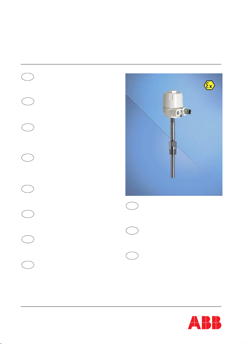
Temperaturfühler TSHD
Sicherheitsrelevante Montagehinweise zum
Betrieb in explosionsgefährdeten Bereichen
nach EU-Richtlinie 94/9 EG (ATEX).
GB
Temperature Sensor TSHD
Installation instructions relevant for security for
the use in potentially explosive atmospheres pursuant to the EC-Directive 94/9 EC (ATEX).
F
Capteur de température TSHD
Indications d'assemblage relevants pour la sécurité, pour l'usage dans des domaines explosifs
en conformité avec la Directive-EC 94/9/EG
(ATEX).
E
Sensor de temperatura TSHD
Instrucciones de montaje relevantes para la
seguridad para la operación en áreas con
riesgo de explosión según Directiva-CE 94/9/CE
(ATEX ).
DK
Temperaturføler TSHD
Sikkerhedsrelevante monteringshenvisninger til
anvendelse i områder med fare for eksplosion i
henhold til EU-direktiv 94/9 EF (ATEX).
I
Sensore di temperatura TSHD
Istruzioni di montaggio rilevanti per la sicurezza
per l'uso in aree a rischio di esplosione, in
conformità alla Direttiva UE 94/9/CE (ATEX).
NL
Temperatuursensor TSHD
Veiligheidsrelevante montagevoorschriften
voor het gebruik in explosieve omgevingen
volgens de EU-richtlijn 94/9 EG (ATEX).
P
Sensor de temperatura TSHD
Instruções de montagem relevantes para a
segurança durante o funcionamento em áreas
com perigo de explosão segundo a Directiva
CE 94/9 CE (ATEX).
Temperaturfühler TSHD
Temperature Sensor TSHD
(SensyTemp Exd)
S
Temperaturgivare TSHD
Säkerhetsrelevanta monteringsanvisningar
för användning i explosionsfarlig miljö enligt
EU-direktiv 94/9 EG (ATEX).
FIN
Lämpötila-anturi TSHD
Turvallisuuden kannalta oleellisia asennusohjeita
käyttöön räjähdysvaaran alaisilla alueilla
EU-direktiivin 94/9 EY (ATEX) mukaan.
GR
Αισθητήρας θερµοκρασίας TSHD
Οδηγίες συναρµολόγησης που αφορούν την
ασφάλεια για λειτουργία σε περιοχές µε κίνδυνο
έκρηξης σύµφωνα µε την οδηγία ΕΕ 94/9 EΟΚ
(ATEX).

Inhalt/Content/Sommaire/Indice . . . . . . . . . . . . . . . . . . . . . . . . . Seite/Page/Página
D
Deutsch . . . . . . . . . . . . . . . . . . . . . . . . . . . . . . . . . . . . . . . . . . . . . . . . . . . . . . . . . . .D 1
GB
English . . . . . . . . . . . . . . . . . . . . . . . . . . . . . . . . . . . . . . . . . . . . . . . . . . . . . . . . . . . GB 1
F
Français. . . . . . . . . . . . . . . . . . . . . . . . . . . . . . . . . . . . . . . . . . . . . . . . . . . . . . . . . . . . F 1
E
Español . . . . . . . . . . . . . . . . . . . . . . . . . . . . . . . . . . . . . . . . . . . . . . . . . . . . . . . . . . . . E 1
DK
Dansk . . . . . . . . . . . . . . . . . . . . . . . . . . . . . . . . . . . . . . . . . . . . . . . . . . . . . . . . . . . . .DK 1
I
Italiano . . . . . . . . . . . . . . . . . . . . . . . . . . . . . . . . . . . . . . . . . . . . . . . . . . . . . . . . . I 1
NL
Nederlands . . . . . . . . . . . . . . . . . . . . . . . . . . . . . . . . . . . . . . . . . . . . . . . . . . . NL 1
P
Portugês. . . . . . . . . . . . . . . . . . . . . . . . . . . . . . . . . . . . . . . . . . . . . . . . . . . . . . . .P 1
S
Svenska . . . . . . . . . . . . . . . . . . . . . . . . . . . . . . . . . . . . . . . . . . . . . . . . . . . . . . . .S 1
FIN
Suomi . . . . . . . . . . . . . . . . . . . . . . . . . . . . . . . . . . . . . . . . . . . . . . . . . . . . . . . . FIN 1
GR
Ελληνikά . . . . . . . . . . . . . . . . . . . . . . . . . . . . . . . . . . . . . . . . . . . . . . . . . . . . . GR 1
2 42/10-55 XU

DeutschTemperaturfühler TSHD (SensyTemp Exd)
D
Sicherheitsrelevante Montagehinweise
zum Betrieb in explosionsgefährdeten Bereichen nach EURichtlinie 94/9 EG (ATEX)
Bedienungsanleitung
Druckschrift-Nr.
Ausgabedatum 02.04
Revision 02
Hersteller
ABB Automation Products GmbH
Borsigstraße 2
63755 Alzenau
DEUTSCHLAND
Tel: +49 800 1114411
Fax: +49 800 1114422
CCC-support.deapr@de.abb.com
© Copyright 2004 by ABB Automation Products GmbH
Technische Änderungen vorbehalten
Dieses Dokument ist urheberrechtlich geschützt. Es unterstützt den Anwender bei der sicheren und effizienten Nutzung des Gerätes. Der Inhalt darf weder ganz noch teilweise ohne vorherige Genehmigung des Rechtsinhabers vervielfältigt oder reproduziert werden.
42/10-55 XU
Vorbemerkung . . . . . . . . . . . . . . . . . . . . . . . . . . . . . . . . . . . . . . . . . . . . . . . . . . . . . . . . D 2
1 Allgemeine Angaben . . . . . . . . . . . . . . . . . . . . . . . . . . . . . . . . . . . . . . . . . . . . . . D 2
2 Bestimmungsgemäße Verwendung . . . . . . . . . . . . . . . . . . . . . . . . . . . . . . . . . D 2
2.1 Verwendungsbereich . . . . . . . . . . . . . . . . . . . . . . . . . . . . . . . . . . . . . . . . . . . . . . . .D 2
2.2 Elektrische Leistungsbegrenzung . . . . . . . . . . . . . . . . . . . . . . . . . . . . . . . . . . . . . .D 3
2.2.1 Messumformer mit und ohne Anzeige . . . . . . . . . . . . . . . . . . . . . . . . . . . . . . . . . . .D 3
2.2.2 Messeinsätze ohne Messumformer . . . . . . . . . . . . . . . . . . . . . . . . . . . . . . . . . . . . .D 3
2.3 Thermische Auslegung . . . . . . . . . . . . . . . . . . . . . . . . . . . . . . . . . . . . . . . . . . . . . .D 3
2.3.1 Widerstandsthermometer und Thermoelemente . . . . . . . . . . . . . . . . . . . . . . . . . . .D 3
2.3.2 Feldgehäuse AGLF, AGLFH, AGLFD in Zone 1 . . . . . . . . . . . . . . . . . . . . . . . . . . .D 3
2.3.3 Tabellen . . . . . . . . . . . . . . . . . . . . . . . . . . . . . . . . . . . . . . . . . . . . . . . . . . . . . . . . . .D 4
2.4 Temperaturmessung in Zone 0 . . . . . . . . . . . . . . . . . . . . . . . . . . . . . . . . . . . . . . . .D 5
3Installation . . . . . . . . . . . . . . . . . . . . . . . . . . . . . . . . . . . . . . . . . . . . . . . . . . . . . . D 5
4 Montage und Demontage . . . . . . . . . . . . . . . . . . . . . . . . . . . . . . . . . . . . . . . . . . D 5
4.1 Montage der Temperaturfühler mit Anschlusskopf AGL, AGLH, AGLHD . . . . . . . .D 5
4.2 Montage der Feldgehäuse AGLF, AGLFH, AGLFD . . . . . . . . . . . . . . . . . . . . . . . .D 6
4.3 Demontage . . . . . . . . . . . . . . . . . . . . . . . . . . . . . . . . . . . . . . . . . . . . . . . . . . . . . . .D 7
5 Inbetriebnahme . . . . . . . . . . . . . . . . . . . . . . . . . . . . . . . . . . . . . . . . . . . . . . . . . . D 7
6 Instandhaltung (Wartung und Störungsbeseitigung) . . . . . . . . . . . . . . . . . . D 7
7 Anlage 1: EG-Baumusterprüfbescheinigung (Seite1) . . . . . . . . . . . . . . . . . D 8
8 Anlage 2: Konformitätserklärung . . . . . . . . . . . . . . . . . . . . . . . . . . . . . . . . . . . D 9
42/10-55 XU Temperaturfühler TSHD (SensyTemp Exd) D1
Vorbemerkung
Um Ihnen einen optimalen Gebrauch dieses Dokuments und einen sicheren Einsatz bei Inbetriebnahme, Betrieb und Wartung zu gewährleisten, beachten Sie bitte die folgenden Erklärungen zu den verwendeten Symbolen.
Warnung
STOP
Hinweis, um die Aufmerksamkeit auf ein Risiko oder auf eine Gefährlichkeit zu lenken, die zu einer ernsten Verletzung von Personen oder zum Tode führen kann.
1 Allgemeine Angaben
Bezeichnung
Produktlinie SensyTemp Ex d
– Widerstandsthermometer und Thermoelemente mit Anschlussköpfen des Typs AGL (Stan-
darddeckel), AGLH (hoher Deckel) und AGLHD (Fensterdeckel für Anzeige)
– Feldgehäuse des Typs AGLF (Standarddeckel), AGLFH (hoher Deckel) und AGLFD (Fens-
terdeckel für Anzeige)
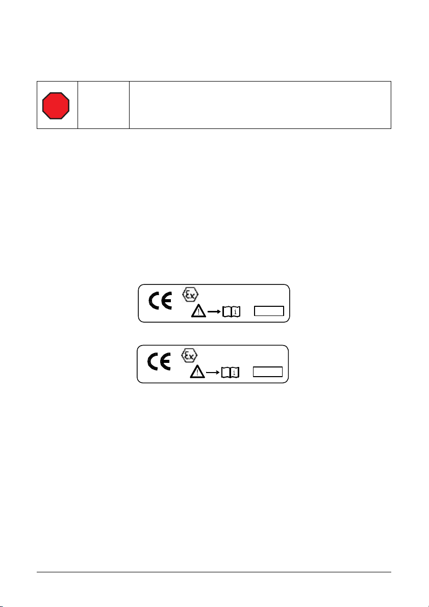
Zusätzliche Ex-Kennzeichnung
Widerstandsthermometer und Thermoelemente mit geeigneten Schutzrohren bzw. Schutzhülsen zur Temperaturmessung in Zone 0:
II 1/2 G EEx d IIC T6
PTB 99 ATEX 1144
0 1 0 2
Sonstige Widerstandsthermometer und Thermoelemente sowie Feldgehäuse:
II 2 G EEx d IIC T6
PTB 99 ATEX 1144
0 1 0 2
2000
2000
2 Bestimmungsgemäße Verwendung
2.1 Verwendungsbereich
Kategorie
Widerstandsthermometer, Thermoelemente und Feldgehäuse der Produktfamilie
SensyTemp Ex d sind Geräte der Gruppe II, Kategorie 2 bzw. 1/2 entsprechend EU-Richtlinie
94/9/EG (ATEX).
Zonen
Widerstandsthermometer, Thermoelemente und Feldgehäuse können in explosionsgefährdeten Bereichen der Zonen 1 und 2 eingesetzt werden. Dabei sind alle geltenden Vorschriften
für den Betrieb elektrischer Geräte innerhalb dieser Gefahrenbereiche zu beachten.
Widerstandsthermometer und Thermoelemente sind mit geeigneten Schutzrohren bzw.
Schutzhülsen (siehe Abschnitt 2.4) zur Temperaturmessung in Zone 0 einsetzbar.
D2 Temperaturfühler TSHD (SensyTemp Exd) 42/10-55 XU

Gruppe
Die Baumusterprüfung PTB 99 ATEX 1144 erfolgte für explosionsfähige Atmosphären der
Gruppe IIC in Übereinstimmung mit EN 50014:1997, EN 50018:1994, EN 50284:1997 und EN
1127-1:1997.
Temperaturklasse
Standardmäßig werden die Geräte mit der Temperaturklasse T6 gekennzeichnet. Falls die
vorhandene explosive Gasatmosphäre eine Kennzeichnung mit der Temperaturklasse T5
oder T4 zulässt, können die Geräte bei höheren Einsatztemperaturen verwendet werden. Die
zulässigen Temperaturbereiche sind in Abschnitt 2.3 festgelegt.
2.2 Elektrische Leistungsbegrenzung
2.2.1 Messumformer mit und ohne Anzeige
Nennbetriebsspannung UB ≤ 60 V AC
Max. Betriebsspannung U
Max. thermische / elektrische Leistung P
= UB + 10%
Bmax
nach Tabelle 2-1 festlegen
max
(Gesamtleistung aller Komponenten)
Max. Betriebsstrom I
Nennstrom Sicherung ≤ I
max
max
= P
/ 1,7
Anzahl Messumformer/Anzeigemodule 0 bis 2
2.2.2 Messeinsätze ohne Messumformer
Nennbetriebsspannung UB ≤ 10 V AC
Max. Betriebsspannung U
Max. thermische bzw. elektrische Leistung P
= UB + 10%
Bmax
nach Tabelle 2-2 u. Tabelle 2-3 festlegen
max
(Gesamtleistung aller Messstellen)
Max. Messstrom Widerstandsthermometer unter 2 mA je Messstelle
Max. Ausgangsspannung Thermoelemente unter 100 mV je Messstelle
Max. Betriebsstrom I
Nennstrom Sicherung ≤ I
max
= P
max
/ 1,7
Anzahl der Messstellen 1 bis 3
max
max
/ U
/ U
oder 60 V DC
eff
Bmax
oder 10 V DC
eff
Bmax
2.3 Thermische Auslegung
2.3.1 Widerstandsthermometer und Thermoelemente
Untere Einsatztemperatur: - 35°C
Obere Einsatztemperatur
Anschlusskopf AGL, AGLH, AGLHD in Zone 1: siehe Tabelle 2-1
Halsrohr in Zone 1: siehe Tabelle 2-1
Messeinsatz in Zone 1: siehe Tabelle 2-2
Messeinsatz in Zone 0
mit geeignetem Schutzrohr bzw. Schutzhülse: siehe Tabelle 2-3
2.3.2 Feldgehäuse AGLF, AGLFH, AGLFD in Zone 1
Untere Einsatztemperatur: - 35°C
Obere Einsatztemperatur: siehe Tabelle 2-1
42/10-55 XU Temperaturfühler TSHD (SensyTemp Exd) D3
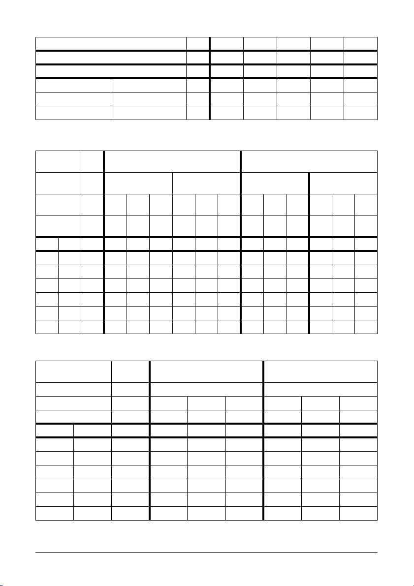
2.3.3 Tabellen
Zugeführte Leistung W 2,0 4,0 6,0 8,0 10,0
Resultier. Erwärmung + Sicherheitszuschlag K 12 19 26 33 40
Temperaturklasse °C °C °C °C °C °C
T4 135 °C °C 123 116 109 102 95
T5 100 °C °C 88 81 74 67 60
T6 85 °C °C 73 66 59 52 45
Tabelle 2-1 Maximal zulässige Einsatztemperaturen der Anschlussköpfe und Feldgehäuse (einschließlich der
Ausführung Mantelwiderstandsthermometer
Schutzrohr mit geeignetem
Zugeführte
Leistung
Result.
in direktem thermischen Kontakt stehenden Halsrohre, Schutzrohre bzw. Schutzhülsen,
Montageplatten usw.)
Mantelthermoelement
Ø 6 mm
Schutzrohr
ohne Schutzrohr mit geeignetem
Ø 6 mm
Schutzrohr
ohne Schutzrohr
W 0,25 0,50 0,75 0,25 0,50 0,75 0,25 0,50 0,75 0,25 0,50 0,75
K 1017251935514 7 105 8 12
Erwärmung
Kl.Temp °C°C°C°C°C°C°C°C°C°C°C°C
T1 450 °C 440 433 425 431 415 399 446 443 440 445 442 438
T2 300 °C 290 283 275 281 265 249 296 293 290 295 292 288
T3 200 °C 190 183 175 181 165 149 196 193 190 195 192 188
T4 135 °C 125 118 110 116 100 84 131 128 125 130 127 123
T5 100 °C 90 83 75 81 65 49 96 93 90 95 92 88
T6 85 °C 75 68 60 66 50 34 81 78 75 80 77 73
Tabelle 2-2 Maximal zulässige Einsatztemperaturen für Widerstandsthermometer und Thermoelemente
in Zone 1
Ausführung Mantelwiderstandsthermometer
Ø 6 mm
Mantelthermoelement
Ø 6 mm
Schutzrohr Mit geeignetem Schutzrohr mit geeignetem Schutzrohr
Zugeführte Leistung W 0,25 0,50 0,75 0,25 0,50 0,75
Result. Erwärmung K 10 17 25 4 7 10
Kl.Temp °C°C°C°C°C°C
T1 360 °C 350 343 335 356 353 350
T2 240 °C 230 223 215 236 233 230
T3 160 °C 150 143 135 156 153 150
T4 108 °C 98 91 83 104 101 98
T5 80 °C 70 63 55 76 73 70
T6 68 °C 58 51 43 64 61 58
Tabelle 2-3 Maximal zulässige Einsatztemperaturen für Widerstandsthermometer und Thermoelemente
in Zone 0
D4 Temperaturfühler TSHD (SensyTemp Exd) 42/10-55 XU

2.4 Temperaturmessung in Zone 0
Zur Temperaturmessung in Zone 0 müssen Schutzrohre bzw. Schutzhülsen verwendet werden, die folgenden Anforderungen erfüllen:
Mindestwandstärken
– 1 mm bei Schutzrohren bzw. Schutzhülsen aus nichtrostendem Stahl (z.B. nach DIN 17440)
bzw. aus korrosionsbeständigen Nickel-Legierungen (z.B. nach DIN 17742)
– 3 mm bei Schutzrohren bzw. Schutzhülsen aus anderen Stählen.
Auslegung
Die Schutzrohre bzw. Schutzhülsen sind hinsichtlich Material und Abmessungen so auszulegen, dass sie den betrieblichen Beanspruchungen mit ausreichenden Sicherheitszuschlägen
dauerhaft standhalten (Temperatur, Druck, strömungsinduzierte Biegung und Schwingung,
Korrosion usw.).
Prüfungen
Die Schutzrohre bzw. Schutzhülsen sind mit dem 1,5-fachen Nenndruck zu prüfen.
3 Installation
STOP
Bei der Installation sind die allgemeinen Anforderungen für die Projektierung, Auswahl und Errichtung elektrischer Anlagen in explosionsgefährdeten Bereichen zu beachten (z.B. EN
60079-14).
Warnung
4 Montage und Demontage
4.1 Montage der Temperaturfühler mit Anschlusskopf AGL, AGLH, AGLHD
Schutzrohre bzw. Schutzhülsen, Halsrohre
Hinweise zu Zone 0:
– geeignete Schutzrohre bzw. Schutzhülsen zur Zonentrennung montieren
– gegebenenfalls Dichtungselemente geeigneter Temperatur-, Druck- und Korrosionsbe-
ständigkeit verwenden.
Temperaturerhöhung durch Wärmezuleitung oder Wärmestau vermeiden (z.B. durch ausreichenden Abstand zu heißen Anlagenteilen und thermischen Isolierungen, Wärmeableitung
durch ungehinderte Luftzirkulation)
Messeinsatz
Nur baumustergeprüfte ABB-Messeinsätze verwenden, deren Durchmesser zur entsprechenden Bohrung des Anschlusskopfs passt (zünddurchschlagsicherer Spalt).
Bei Oberflächenschäden im Bereich des zünddurchschlagsicheren Spaltes Messeinsatz bzw.
Anschlusskopf-Unterteil austauschen.
Leitungsverschraubungen
– Nur gesondert bescheinigte Leitungsverschraubungen geeigneter Schutzart verwenden.
– Zulassungs- und Montagehinweise der Leitungsverschraubung beachten.
– Leitungsverschraubungen mit Gewindekleber montieren (z.B. Loctite 273, nicht erforder-
lich bei NPT -Gewinden, vorher Gewinde auf Beschädigungen prüfen).
42/10-55 XU Temperaturfühler TSHD (SensyTemp Exd) D5

– Verwendete Leitung hinsichtlich Eignung überprüfen (Typ, tatsächlicher Leitungsdurch-
messer usw.).
– Leitungsverschraubung anziehen bis Leitung fest von dem Dichtungsring umschlossen ist.
– Leitung durch zusätzliche Maßnahmen vor mechanischer Belastung (Zug, Torsion usw.)
schützen.
– Nicht benötigte Öffnungen mit zugelassenen Verschlusselementen verschließen.
Potentialausgleichsleiter
Bei sicherem elektrischen Kontakt zu geerdeten metallischen Rohrleitungssystemen (z.B.
über Anschlussgewinde, Flanschschrauben usw.) ist ein Anschluss von Potentialausgleichsleitern nicht erforderlich.
Elektronische Komponenten
– Bei Bedarf elektronische Komponenten mit Montagesets einbauen.
– Elektronische Komponenten entsprechend deren Betriebsanleitung anschließen.
Deckel
Deckel von Hand aufschrauben bis Deckeldichtung zusammengepresst wird und durch Herausschrauben der Sicherungsschraube sichern (vorher Deckelgewinde auf Beschädigungen
prüfen). Deckel nicht mit Schraubschlüssel festziehen (Sechskant und Schlitze sind lediglich
Öffnungshilfen).
4.2 Montage der Feldgehäuse AGLF, AGLFH, AGLFD
Montageart
Das Feldgehäuse ist fest an unbeweglichen Wänden, Trägern, Rohren usw. zu montieren.
Leitungsverschraubungen
– Nur gesondert bescheinigte Leitungsverschraubungen geeigneter Schutzart verwenden.
– Zulassungs- und Montagehinweise der Leitungsverschraubung beachten.
– Leitungsverschraubungen mit Gewindekleber montieren ( z.B. Loctite 273, nicht erforder-
lich bei NPT -Gewinden, vorher Gewinde auf Beschädigungen prüfen).
– Verwendete Leitung hinsichtlich Eignung überprüfen (Typ, tatsächlicher Leitungsdurch-
messer usw.).
– Leitungsverschraubung anziehen bis Leitung fest von dem Dichtungsring umschlossen ist.
– Leitung durch zusätzliche Maßnahmen vor mechanischer Belastung (Zug, Torsion usw.)
schützen.
– Nicht benötigte Öffnungen mit zugelassenen Verschlusselementen verschließen.
Potentialausgleichsleiter
Bei sicherem elektrischen Kontakt zu geerdeten metallischen Rohrleitungssystemen (z.B.
über metallische Montageplatte mit Bügelschrauben usw.) ist ein Anschluss von Potentialausgleichsleitern nicht erforderlich.
Elektronische Komponenten
– Bei Bedarf elektronische Komponenten mit Montagesets einbauen.
– Elektronische Komponenten entsprechend deren Betriebsanleitung anschließen.
Deckel
Deckel von Hand aufschrauben bis Deckeldichtung zusammengepresst wird und durch Herausschrauben der Sicherungsschraube sichern (vorher Deckelgewinde auf Beschädigungen
prüfen). Deckel nicht mit Schraubschlüssel festziehen (Sechskant und Schlitze sind lediglich
Öffnungshilfen).
D6 Temperaturfühler TSHD (SensyTemp Exd) 42/10-55 XU

4.3 Demontage
STOP
Der Deckel darf nur im spannungsfreien Zustand geöffnet werden. Je nach eingebauten elektrischen Komponenten und der Betriebssituation (Störung usw.) muss vor dem Öffnen des
Deckels eine hinreichend lange Wartezeit zur Entladung und Abkühlung eingehalten werden.
Warnung
5 Inbetriebnahme
STOP
Vor Inbetriebnahme sind zu prüfen:
– Ordnungsgemäße Montage und Dichtheit der Schutzrohre bzw. Schutzhülsen (insbeson-
– Ordnungsgemäße Montage aller erforderlichen Komponenten am Anschlusskopf bzw.
– Anschluss der Potentialausgleichsleiter (bei Bedarf).
Warnung
dere bei Verwendung als Trennelement zur Zone 0).
Feldgehäuse (Messeinsatz, Leitungsverschraubung, Leitung, Deckel usw.) entsprechend
den Anforderungen für die Zündschutzart „d" (druckfeste Kapselung).
6 Instandhaltung (Wartung und Störungsbeseitigung)
STOP
Warnung
– Gehäuse, Leitungen, Leitungsverschraubungen, Potentialausgleichsleiter usw. sind in Ab-
hängigkeit von den betrieblichen Belastungen in hinreichend kurzen Abständen auf Be-
schädigungen zu prüfen.
– Bei Defekten an den schutzartrelevanten Merkmalen (Gehäuse, Leitung, Leitungsver-
schraubung, Potentialausgleichsleiter usw.) ist das Betriebsmittel umgehend außer Betrieb
zu setzen und spannungsfrei zu schalten. Eine Wiederinbetriebnahme ist nur nach Wieder-
herstellung des ordnungsgemäßen Zustands erlaubt.
– Für beschädigte oder verschlissene Komponenten dürfen nur typgeprüfte ABB-Ersatzteile
verwendet werden (insbesondere Messeinsätze, Messumformer, Anzeigen, Dichtungen
usw.).
– Nicht autorisierte Reparaturarbeiten an dem druckgekapselten Gehäuse sind verboten.
– Schutzrohre bzw. Schutzhülsen mit der Funktion eines Trennelementes zur Zone 0 sind in
die wiederkehrenden Prüfungen des Gesamtsystems einzubeziehen.
42/10-55 XU Temperaturfühler TSHD (SensyTemp Exd) D7
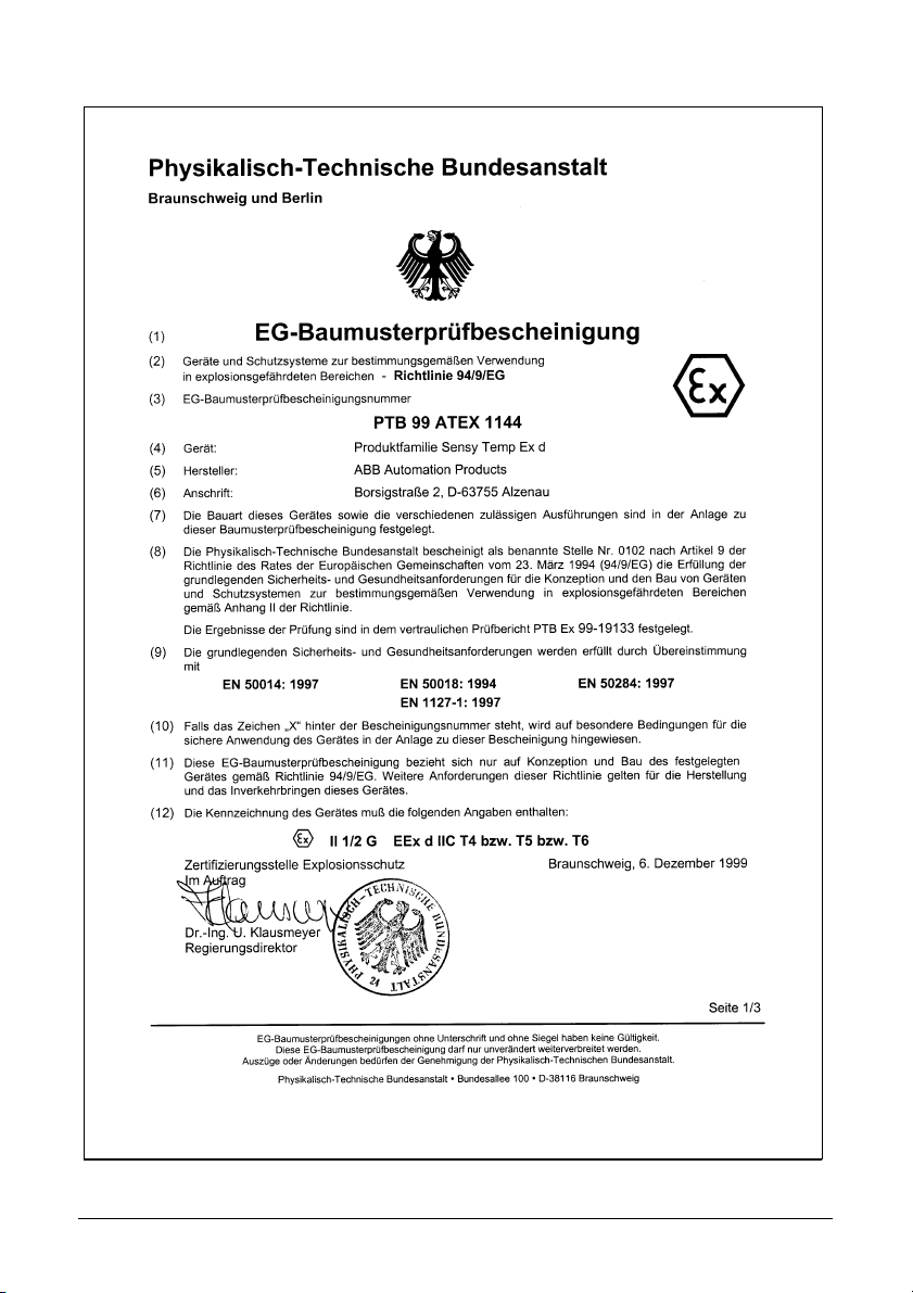
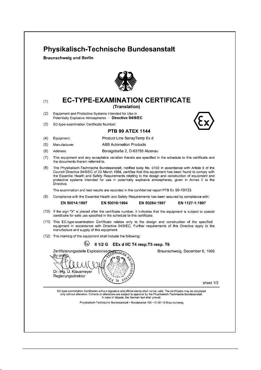
7 Anlage 1: EG-Baumusterprüfbescheinigung (Seite1)
D8 Temperaturfühler TSHD (SensyTemp Exd) 42/10-55 XU
8 Anlage 2: Konformitätserklärung
42/10-55 XU Temperaturfühler TSHD (SensyTemp Exd) D9

EnglishTemperature Sensor TSHD (SensyTemp Exd)
GB
Installation instructions relevant for security for the use in potentially explosive atmospheres
pursuant to the EC-Directive 94/9 EC (ATEX).
User manual
Document No.
Date of issue 02.04
Revision 02
Manufacturer
ABB Automation Products GmbH
Borsigstraße 2
63755 Alzenau
Germany
Tel: +49 551 905-534
Fax: +49 551 905-555
CCC-support.deapr@de.abb.com
© Copyright 2004 by ABB Automation Products GmbH
We reserve the right to technical amendments
This document is protected by copyright. Information in this document is intended only to assist the user in safe and efficient operation of the equipment. Its contents are not to be reproduced in full or part without prior approval of legal owner.
42/10-55 XU
Important information in advance . . . . . . . . . . . . . . . . . . . . . . . . . . . . . . . . . . . . . . GB 2
1 General data . . . . . . . . . . . . . . . . . . . . . . . . . . . . . . . . . . . . . . . . . . . . . . . . . . . . GB 2
2 Intended usage . . . . . . . . . . . . . . . . . . . . . . . . . . . . . . . . . . . . . . . . . . . . . . . . . GB 2
2.1 Range of application . . . . . . . . . . . . . . . . . . . . . . . . . . . . . . . . . . . . . . . . . . . . . . GB 2
2.2 Electrical power limitation . . . . . . . . . . . . . . . . . . . . . . . . . . . . . . . . . . . . . . . . . . GB 3
2.2.1 Transmitter with and without indicator . . . . . . . . . . . . . . . . . . . . . . . . . . . . . . . . . GB 3
2.2.2 Measuring inset without transmitter . . . . . . . . . . . . . . . . . . . . . . . . . . . . . . . . . . . GB 3
2.3 Operating temperature range . . . . . . . . . . . . . . . . . . . . . . . . . . . . . . . . . . . . . . . GB 3
2.3.1 RTDs and TCs . . . . . . . . . . . . . . . . . . . . . . . . . . . . . . . . . . . . . . . . . . . . . . . . . . . GB 3
2.3.2 Field housings AGLF, AGLFH, AGLFD within zone 1 . . . . . . . . . . . . . . . . . . . . . GB 3
2.3.3 Tables . . . . . . . . . . . . . . . . . . . . . . . . . . . . . . . . . . . . . . . . . . . . . . . . . . . . . . . . . GB 4
2.4 Temperature measurement within zone 0 . . . . . . . . . . . . . . . . . . . . . . . . . . . . . . GB 5
3Installation . . . . . . . . . . . . . . . . . . . . . . . . . . . . . . . . . . . . . . . . . . . . . . . . . . . . . GB 5
4 Assembling and disassembling . . . . . . . . . . . . . . . . . . . . . . . . . . . . . . . . . . . GB 5
4.1 Assembling of RTD and TC with connection head AGL, AGLH, AGLHD . . . . . . GB 5
4.2 Assembling of field housings AGLF, AGLFH, AGLFD . . . . . . . . . . . . . . . . . . . . . GB 6
4.3 Disassembling . . . . . . . . . . . . . . . . . . . . . . . . . . . . . . . . . . . . . . . . . . . . . . . . . . . GB 7
5 Initial operation . . . . . . . . . . . . . . . . . . . . . . . . . . . . . . . . . . . . . . . . . . . . . . . . . GB 7
6 Maintenance and trouble-shooting . . . . . . . . . . . . . . . . . . . . . . . . . . . . . . . . GB 7
7 Enclosure 1: EC-Type-Examination (page 1) . . . . . . . . . . . . . . . . . . . . . . . . GB 8
8 Enclosure 2: Declaration of conformity . . . . . . . . . . . . . . . . . . . . . . . . . . . . GB 9
42/10-55 XU Temperature Sensor TSHD (SensyTemp Exd) GB1
Important information in advance
Observe the warnings, cautions, notices and important information marked with the symbols
listed below to ensure optimum use of this operating manual and safe, operation and maintenance of the device.
Warning
STOP
Indicates a risk or potentially hazardous situation which, if not avoided, could result in death or serious injury.
1 General data
Designation
Product line SensyTemp Ex d
– Resistance temperature detectors (RTD) and thermocouples (TC) provided with connection
heads of the type AGL (standard cover), AGLH (high cover) and AGLHD (window cover for
indicator)
– Field housing of the type AGLF (standard cover), AGLFH (high cover) and AGLFD (window
cover for indicator)
Additional Ex-marking
RTD and TC with appropriate thermowells or protection tubes for temperature meas-urement
within zone 0::
II 1/2 G EEx d IIC T6
PTB 99 ATEX 1144
0 1 0 2
Other RTD and TC as well as field housings::
0 1 0 2
II 2 G EEx d IIC T6
PTB 99 ATEX 1144
2000
2000
2 Intended usage
2.1 Range of application
Category
RTD, TC and field housings of the product line SensyTemp Ex d are devices of group II, category 2 respectively 1/2 according to EU-directive 94/9/EC (ATEX).
Zones
RTD, TC and field housings can be used within potentially explosive atmospheres of zones 1
and 2 in compliance with all applicable regulations regarding the use of electrical equipment
in such hazardous areas.
RTD and TC with appropriate thermowells or protection tubes are applicable to temperature
measurement within zone 0 (see section 2.4).
GB2 Temperature Sensor TSHD (SensyTemp Exd) 42/10-55 XU

Groups
The type examination PTB 99 ATEX 1144 was executed for potentially explosive atmospheres
of group IIC according to EN 50014:1997, EN 50018:1994, EN 50284:1997, and EN 11271:1997.
Temperature class
The devices are normally marked with temperature class T6. Higher operating temperatures
are possible in case of potentially explosive atmospheres permissible for temperature class
T5 or T4. Operating temperature ranges are defined in section 2.3.
2.2 Electrical power limitation
2.2.1 Transmitter with and without indicator
Rated supply voltage UB ≤ 60 V AC
Maximum supply voltage U
Maximum thermal / electrical power P
= UB + 10%
Bmax
determined according to Table 2-1
max
(overall power consumption of all electric
components)
Maximum current of power supply I
Rated current of fuse ≤ I
max
max
= P
/ 1,7
Number of electric transmitters/indicators 0 to 2
2.2.2 Measuring inset without transmitter
Rated supply voltage UB ≤ 10 V AC
Maximum supply voltage U
Maximum thermal / electrical power P
= UB + 10%
Bmax
determined according to Table 2-2 and
max
Table 2-3 (overall power consumption of all
electric components)
Maximum measuring current of TTDs below 2 mA each sensor element
Maximum output voltage of TCs below 100 mV each sensor element
Maximum current of power supply I
Rated current of fuse ≤ I
max
= P
max
/ 1,7
Number of sensor elements 1 to 3
max
max
/ U
/ U
oder 60 V DC
eff
Bmax
oder 10 V DC
eff
Bmax
2.3 Operating temperature range
2.3.1 RTDs and TCs
Lower operating temperature - 35°C
Upper operating temperature
Connection head AGL, AGLH, AGLHD within zone 1: see Table 2-1
extension tube within zone 1: see Table 2-1
measuring inset within zone 1: see Table 2-2
measuring inset with appropriate thermowell or
protection tube within zone 0: see Table 2-3
2.3.2 Field housings AGLF, AGLFH, AGLFD within zone 1
Lower operating temperature: - 35°C
Upper operating temperature: see Table 2-1
42/10-55 XU Temperature Sensor TSHD (SensyTemp Exd) GB3

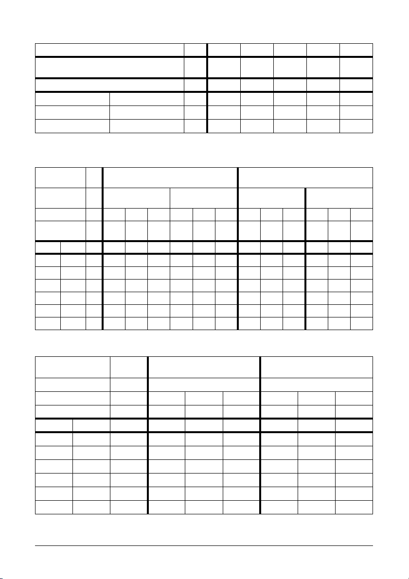
2.3.3 Tables
Power consumption W 2,0 4,0 6,0 8,0 10,0
Resulting temp. rise (incl. 5 K safety margin) K 12 19 26 33 40
Temperature class °C °C °C °C °C °C
T4 135 °C °C 123 116 109 102 95
T5 100 °C °C 88 81 74 67 60
T6 85 °C °C 73 66 59 52 45
Table 2-1 Maximum permissible operating temperatures of connection heads and field housings
(including extension tubes, thermowells, protection tubes, assembling sets etc. with
direct thermal contact)
Type RTD inset
Protection
tube
Power
consumpt.
Result. temperatue rise
Ø 6 mm
with appropriate
protection tube
W 0,25 0,50 0,75 0,25 0,50 0,75 0,25 0,50 0,75 0,25 0,50 0,75
K 1017251935514 7 105 8 12
without
protection tube
TC inset
Ø 6 mm
with appropriate
protection tube
without
protection tube
ClassTemp °C°C°C°C°C°C°C°C°C°C°C°C
T1 450 °C 440 433 425 431 415 399 446 443 440 445 442 438
T2 300 °C 290 283 275 281 265 249 296 293 290 295 292 288
T3 200 °C 190 183 175 181 165 149 196 193 190 195 192 188
T4 135 °C 125 118 110 116 100 84 131 128 125 130 127 123
T5 100 °C 90 83 75 81 65 49 96 93 90 95 92 88
T6 85 °C 75 68 60 66 50 34 81 78 75 80 77 73
Table 2-2 Maximum permissible operating temperatures of RTD and TC insets within zone 1
Type RTD inset
Ø 6 mm
TC inset
Ø 6 mm
Protection tube With appropriate protection tube With appropriate protection tube
Power consumption W 0,25 0,50 0,75 0,25 0,50 0,75
Result. temperat. rise K 10 17 25 4 7 10
Kl.Temp °C°C°C°C°C°C
T1 360 °C 350 343 335 356 353 350
T2 240 °C 230 223 215 236 233 230
T3 160 °C 150 143 135 156 153 150
T4 108 °C 98 91 83 104 101 98
T5 80 °C 70 63 55 76 73 70
T6 68 °C 58 51 43 64 61 58
Table 2-3 Maximum permissible operating temperatures of RTD and TC insets within zone 0
GB4 Temperature Sensor TSHD (SensyTemp Exd) 42/10-55 XU

2.4 Temperature measurement within zone 0
Use appropriate thermowells or protection tubes for temperature measuring within zone 0.
They must meet following requirements:
Minimum wall thickness
– 1 mm in the case of thermowells respectively protection tubes made of stainless steel (i.e.
according to DIN 17440) or made of non-corrosive nickel alloys (i.e. according to DIN
17742)
– 3 mm in the case of thermowells respectively protection tubes made of other steels
Design
Material and dimensions of thermowells and protection tubes have to be specified to resist
permanently all operating loads with sufficient safety margins (temperature, pressure, flow induced bending stress and vibration, corrosion etc.).
Testing
Thermowells and protection tubes have to be pressure tested with 1,5 times of the nominal
pressure.
3 Installation
Warning
STOP
The general requirements for planning, selection and installation of electrical equipment within
potentially explosive atmospheres have to be observed (i.e. EN 60079-14).
4 Assembling and disassembling
4.1 Assembling of RTD and TC with connection head AGL, AGLH, AGLHD
Thermowells or protection tubes, extension tubes
Indications referring to zone 0 applications:
– Assemble appropriate thermowells or protection tubes for the separation of zones
– Use seals with appropriate temperature, pressure, and corrosion resistance if necessary
Prevent raising of temperature due to heat flow or heat accumulation (i.e. by sufficient dis-
tance to hotter components and thermal insulation, heat dissipation by sufficient air circulation)
Measuring insets
Use only approved ABB measuring insets with appropriate diameter for the corresponding
bore of the connection head (ignition-proof gap).
Exchange inset respectively connection head in case of surface defects in the range of the
ignition-proof gap.
Cable glands
– Use only approved cable glands of the proper protection class.
– Observe certification and installation instructions of the cable glands.
– Screw in cable glands with appropriate thread securer (e.g. Loctite 273, not necessary for
NPT threads, check threads for damages before).
42/10-55 XU Temperature Sensor TSHD (SensyTemp Exd) GB5

– Verify used cable for suitability (type, actual outside diameter, etc).
– Tighten cable gland until the cable is firmly fixed and sealed by the sealing ring.
– Protect cable against mechanical loads (tension, torsion, etc) with suitable installation
measures.
– Close openings, which are not needed with certified plugs.
Grounding terminals
Additional grounding connections are not necessary in case of reliable electrical contact to
grounded conductive tubing systems or other grounded conductive supporting structures (e.g.
via connection threads or flange screws).
Electrical components
– Assemble electrical components with assembling sets (if needed).
– Connect electrical components according to the relevant operating instructions.
Cover
– Screw on cover manually until O seal is compressed (check threads for damages before)
and secure cover with the locking screw.
– Do not use any wrenches to tighten the cover (hexagons and recesses are only opening
aids).
4.2 Assembling of field housings AGLF, AGLFH, AGLFD
Installation
Install field housings permanently to fixed walls, supports or pipes.
Cable glands
– Use only approved cable glands of the proper protection class.
– Observe certification and installation instructions of the cable glands.
– Screw in cable glands with appropriate thread securer (e.g. Loctite 273, not necessary for
NPT threads, check threads for damages before).
– Verify used cable for suitability (type, actual outside diameter, etc.).
– Tighten cable gland until the cable is firmly fixed and sealed by the sealing ring.
– Protect cable against mechanical loads (tension, torsion, etc.) with suitable installation
measures.
– Close openings, which are not needed with certified plugs.
Grounding terminals
Additional grounding connections are not necessary in case of reliable electrical contact to
grounded conductive tubing systems or other grounded conductive supporting structures (e.g.
via metallic mounting plate).
Electrical components
– Assemble electrical components with assembling sets (if needed).
– Connect electrical components according to the relevant operating instructions.
Cover
– Screw on cover manually until O seal is compressed (check threads for damages before)
and secure cover with the locking screw.
– Do not use any wrenches to tighten the cover (hexagons and recesses are only opening
aids).
GB6 Temperature Sensor TSHD (SensyTemp Exd) 42/10-55 XU

4.3 Disassembling
Warning
STOP
Do not open cover when electrical circuits are alive. Wait sufficient time for discharge and
cooling down before opening of cover (depends on operation conditions, malfunction and so
on).
5 Initial operation
Warning
STOP
Verify before initial operation:
– Proper assembling and tightness of thermowells and protection tubes (especially in case of
partition walls to zone 0)
– Proper assembling of all required components at connection head or field housing accor-
ding to all requirements relevant for flameproof protection (measuring inset, cable gland, ca-
ble, cover etc.)
– Connection of grounding terminal (if necessary)
6 Maintenance and trouble-shooting
Warning
STOP
– Check enclosures, cables, cable glands, grounding connections etc. for damages and wear
in sufficient intervals depending on expected operation load.
– Disconnect and stop operation immediately in case of defects concerning flameproof rele-
vant features (enclosure, cable, cable glands, grounding connections etc.). Do not start ope-
ration again until restoring the proper condition.
– Replace damaged or worn components by approved ABB spar parts only (especially insets,
transmitters, displays, seals, and so on)
– Do not carry out any unauthorized repair work on any part of the flameproof enclosure.
– Check pressure loaded components (thermowells, protection tubes, flanges etc.) during
routine pressure testing especially in case of partition walls to zone 0.
42/10-55 XU Temperature Sensor TSHD (SensyTemp Exd) GB7
7 Enclosure 1: EC-Type-Examination (page 1)
GB8 Temperature Sensor TSHD (SensyTemp Exd) 42/10-55 XU
8 Enclosure 2: Declaration of conformity
42/10-55 XU Temperature Sensor TSHD (SensyTemp Exd) GB9

FrançaisCapteur de température TSHD
F
(SensyTemp Exd)
Indications d'assemblage relevants pour la sécurité, pour l'usage dans des domaines
explosifs en conformité avec la DirectiveEC 94/9/EG (ATEX).
Mode d’emploi
Documentation N°
Date d’edition 02.04
Revision 02
Fabricant
ABB Automation Products GmbH
Borsigstraße 2
63755 Alzenau
Allemagne
Tel: +49 551 905-534
Fax: +49 551 905-555
CCC-support.deapr@de.abb.com
© Copyright 2004 by ABB Automation Products GmbH
Sous réserve de modifications techniques.
Cette documentation est protégée par un copyright. La traduction, la reproduction et la diffusion sous quelque forme que ce soit - existants ou à venir - en particulier l'impression photomécanique ou électronique et le stockage sur support ou réseau informatique n'est pas
permis sans l'autorisation préalable du propriétaire du copyright et le non respect de ces dispositions est passible de poursuites civiles et pénales.
Important information in advance . . . . . . . . . . . . . . . . . . . . . . . . . . . . . . . . . . . . . . . .F 2
1 Généralités . . . . . . . . . . . . . . . . . . . . . . . . . . . . . . . . . . . . . . . . . . . . . . . . . . . . . . . F 2
2 Conditions d'utilisation . . . . . . . . . . . . . . . . . . . . . . . . . . . . . . . . . . . . . . . . . . . .F 2
2.1 Domaine d'application . . . . . . . . . . . . . . . . . . . . . . . . . . . . . . . . . . . . . . . . . . . . . . .F 2
2.2 Limitation de puissance électrique . . . . . . . . . . . . . . . . . . . . . . . . . . . . . . . . . . . . . F 3
2.2.1 Transmetteur avec et sans indicateur . . . . . . . . . . . . . . . . . . . . . . . . . . . . . . . . . . . F 3
2.2.2 Elément de mesure sans transmetteur . . . . . . . . . . . . . . . . . . . . . . . . . . . . . . . . . . F 3
2.3 Domaine d'utilisation en température . . . . . . . . . . . . . . . . . . . . . . . . . . . . . . . . . . . F 3
2.3.1 Sondes à résistance et thermocouples . . . . . . . . . . . . . . . . . . . . . . . . . . . . . . . . . . F 3
2.3.2 Boîtiers locaux AGLF, AGLFH, AGLFD en zone 1 . . . . . . . . . . . . . . . . . . . . . . . . . F 3
2.3.3 Tableaux . . . . . . . . . . . . . . . . . . . . . . . . . . . . . . . . . . . . . . . . . . . . . . . . . . . . . . . . .F4
2.4 Mesure de température en zone 0 . . . . . . . . . . . . . . . . . . . . . . . . . . . . . . . . . . . . . F 5
3Installation . . . . . . . . . . . . . . . . . . . . . . . . . . . . . . . . . . . . . . . . . . . . . . . . . . . . . . . F 5
4 Montage et démontage . . . . . . . . . . . . . . . . . . . . . . . . . . . . . . . . . . . . . . . . . . . . . F 5
4.1 Montage de RTD et TC avec les têtes de raccordement . . . . . . . . . . . . . . . . . . . . F 5
4.2 Montage des boîtiers locaux AGLF, AGLFH, AGLFD . . . . . . . . . . . . . . . . . . . . . . .F 6
4.3 Démontage . . . . . . . . . . . . . . . . . . . . . . . . . . . . . . . . . . . . . . . . . . . . . . . . . . . . . . . F 7
5 Mise en service . . . . . . . . . . . . . . . . . . . . . . . . . . . . . . . . . . . . . . . . . . . . . . . . . . . F 7
6 Maintenance et dépannage . . . . . . . . . . . . . . . . . . . . . . . . . . . . . . . . . . . . . . . . .F 7
7 Annexe 1: Certificat CE d’agrément de type (page1) . . . . . . . . . . . . . . . . . . .F 8
8 Annexe 2: Déclaration de conformité . . . . . . . . . . . . . . . . . . . . . . . . . . . . . . . . F 9
42/10-55 XU
42/10-55 XU Capteur de température TSHD (SensyTemp Exd) F1

Informations importantes
Pour permettre une utilisation optimale de ce mode d’emploi ainsi qu’une utilisation des assemblages en toute sécurité lors de la mise en service, du fonctionnement et de la maintenance, respecter les explications suivantes concernant les symboles utilisés
.
Avertissement
STOP
Indique un risque ou une situation potentiellement dangereuse qui pourrait causer la mort ou les blessures sérieuses de
personnes.
1 Généralités
Désignation
Ligne de produits SensyTemp Ex d
– sondes à résistance (RTD) et thermocouples (TC) avec têtes de raccordement de type
AGL (couvercle standard), AGLH (couvercle surélevé) et AGLD (couvercle avec vitre pour
indicateur)
– boîtier locaux de type AGLF (couvercle standard), AGLFH (couvercle surélevé) et AGLFD
(couvercle avec vitre pour indicateur)
Marquage Ex additionnel
RTD et TC avec puits thermométriques appropriés à la mesure de température en zone 0::
II 1/2 G EEx d IIC T6
PTB 99 ATEX 1144
0 1 0 2
Autre RTD et TC et boitiers locaux::
0 1 0 2
II 2 G EEx d IIC T6
PTB 99 ATEX 1144
2000
2000
2 Conditions d'utilisation
2.1 Domaine d'application
Catégorie
Les RTD, TC et les boîtiers locaux de la ligne de produits Sensytemp Ex d sont des appareils
du groupecII, catégorie 2 resp. 1/2 suivant la directive européenne 94/9/EC (ATEX).
Zones
Les RTD, TC et les boîtiers locaux peuvent être utilisés dans des atmosphères dangereuses
des zones 1 et 2 en respectant les règles applicables relatives à l'utilisation d'appareillage
électrique dans ces zones.
F2 Capteur de température TSHD (SensyTemp Exd) 42/10-55 XU

Groupes
La certification de type PTB 99 ATEX 1144 est relative aux zones potentiellement explosives
du groupe IIC conformément aux normes EN 50014:1997, EN 50018:1994, EN 50284:1997,
EN 1127-1:1997.
Classe de température
Les appareils portent en standard le marquage T6. Des températures d'utilisation supérieures
sont autorisées dans des atmosphères potentiellement explosives avec une classe de température T5 ou T4. es plages de température admissible figurent au paragraphe 2.3.
2.2 Limitation de puissance électrique
2.2.1 Transmetteur avec et sans indicateur
Tension d'alimentation U
Tension d'alimentation maximum U
Puissance thermique/électrique maximum P
Intensité maximum de l'alimentation I
Intensité nominale de protection ≤ Imax / 1,7
Nombre de transmett./indicateurs électriques 0 à 2
2.2.2 Elément de mesure sans transmetteur
Tension d'alimentation U
Tension d'alimentation maximum U
Puissance thermique/électrique maximum P
Courant de mesure maximum des RTD inférieur à 2 mA pour chaque sonde
Courant de mesure maximum des TC inférieur à 100 mV pour chaque élément
Intensité nominale de protection ≤ I
Nombre de voies de mesure 1 à 3
≤ 60 V CA
B
= UB + 10%
Bmax
suivant le Tableau 2-1
max
ou 60 V CC
eff
(consommation électrique totale de tous les
composants)
= P
max
≤ 10 V CA
B
Bmax
max
/ U
max
Bmax
ou 10 V CC
eff
= UB + 10%
suivant les Tableau 2-2 et Tableau 2-3
(consommation électrique totale de tous les
composants)
/ 1,7
max
2.3 Domaine d'utilisation en température
2.3.1 Sondes à résistance et thermocouples
Température minimum de fonctionnement -35 °C
Température maximum de fonctionnement
Tête de raccordement AGL, AGLH, AGLHD en zone 1: voir Tableau 2-1
Extension en zone 1: voir Tableau 2-1
Elément de mesure en zone 1: voir Tableau 2-2
Elément de mesure avec puits thermométrique ou
Tube protecteur en zone 0 voir Tableau 2-3
2.3.2 Boîtiers locaux AGLF, AGLFH, AGLFD en zone 1
Température minimum de fonctionnement - 35°C
Température maximum de fonctionnement voir Tableau 2-1
42/10-55 XU Capteur de température TSHD (SensyTemp Exd) F3
2.3.3 Tableaux
Consommation électrique W 2,0 4,0 6,0 8,0 10,0
Accroissement de température résultant (avec
K1219263340
marge de sécurité)
Classe de température °C °C °C °C °C °C
T4 135 °C °C 123 116 109 102 95
T5 100 °C °C 88 81 74 67 60
T6 85 °C °C 73 66 59 52 45
Tableau 2-1 Température maximale admissible de la tête de raccordement et du boîtier (y compris celle due au
transfert thermique de l'extension, du tube protecteur ou du puits, du support de montage, etc… en
contact direct)
Exécution Sonde à résistance chemisée
Protecteur avec protecteur
Ø 6 mm
conforme
sans protecteur avec protecteur
Thermocouple chemisé
Ø 6 mm
conforme
sans protecteur
Consommation W 0,25 0,50 0,75 0,25 0,50 0,75 0,25 0,50 0,75 0,25 0,50 0,75
Echauf. résul-
tant
K1017251935514 7 105 8 12
Classe Temp. °C °C °C °C °C °C °C °C °C °C °C °C
T1 450 °C 440 433 425 431 415 399 446 443 440 445 442 438
T2 300 °C 290 283 275 281 265 249 296 293 290 295 292 288
T3 200 °C 190 183 175 181 165 149 196 193 190 195 192 188
T4 135 °C 125 118 110 116 100 84 131 128 125 130 127 123
T5 100°C908375816549969390959288
T6 85 °C 75 68 60 66 50 34 81 78 75 80 77 73
Tableau 2-2 température maximales d'utilisation pour les capteurs à sonde à résistance et à thermocouple
Exécution Sonde à résistance chemisée
en zone 1
Ø 6 mm
Thermocouple chemisé
Ø 6 mm
Protecteur avec protecteur conforme avec protecteur conforme
Consommation W 0,25 0,50 0,75 0,25 0,50 0,75
Echauf. résultant K 10 17 25 4 7 10
ClasseTemp. °C°C°C°C°C°C
T1 360 °C 350 343 335 356 353 350
T2 240 °C 230 223 215 236 233 230
T3 160 °C 150 143 135 156 153 150
T4 108 °C 98 91 83 104 101 98
T5 80 °C 70 63 55 76 73 70
T6 68 °C 58 51 43 64 61 58
Tableau 2-3 température maximales d'utilisation pour les capteurs à sonde à résistance et à thermocouple
en zone 0
F4 Capteur de température TSHD (SensyTemp Exd) 42/10-55 XU

2.4 Mesure de température en zone 0
Utiliser des puits ou des tubes protecteurs conformes aux règles d'utilisation en zone 0 devant
respecter les caractéristiques suivantes:
Epaisseur de paroi minimum
– 1 mm pour des puits ou des tubes protecteurs en inox (par ex. suivant DIN 17440) ou en
alliage inoxydables à base de nickel (par ex. suivant DIN 17742).
– 3 mm pour des puits ou des tubes protecteurs en autre matériau.
Construction
Les tubes protecteurs ou les puits doivent être conçus pour résister en permanence aux conditions de service avec une marge de sécurité suffisante (température, pression, contraintes
induites par l'écoulement, corrosion etc…).
Tests
Les tubes protecteurs ou les puits doivent être éprouvés à 1,5 x la pression nominale.
3 Installation
Avertissement
STOP
Les normes de conception, de sélection et d'installation relatives aux équipements électriques
installés en zone dangereuse doivent être respectées (par ex. EN 60079-14).
4 Montage et démontage
4.1 Montage de RTD et TC avec les têtes de raccordement
AGL, AGLH, AGLHD
Tubes protecteurs et puits, extensions
Recommandations concernant la zone 0:
– utiliser des puits ou des tubes de protection appropriés pour assurer la séparation des zo-
nes
– utiliser éventuellement des joints résistant aux conditions de température, de pression et à
la corrosion.
Eviter l'élévation de la température due à la conduction ou à l'accumulation de chaleur (par
ex. avec une distance suffisante des surfaces chaudes ou un calorifugeage et avec une dissipation de chaleur suffisante avec circulation forcée d'air).
Elément de mesure
N'utiliser que des pièces de rechange ABB, avec certificat de conformité, adaptées au diamètre de perçage de la tête de raccordement (passage de flamme).
En cas de détérioration des surfaces du passage de flamme changer la base de la tête de
raccordement ou l'élément de mesure endommagé.
Presse étoupe
N'utiliser que des presse étoupe agréés avec le type de protection convenable
– respecter la certification et les instructions de montage des presse étoupe.
42/10-55 XU Capteur de température TSHD (SensyTemp Exd) F5

– Visser les presse étoupe en utilisant un frein de filetage (par ex. loctite 273, non nécessaire
pour les filetages NPT, vérifier au préalable le bon état du filetage).
– Vérifier la compatibilité du câble utilisé (type, diamètre extérieur, etc…).
– Serrer le presse étoupe jusqu'à ce que le câble soit fermement fixé par la bague interne
– Protéger la câble des contraintes mécaniques (tension, torsion, etc…) par un montage ap-
proprié.
– Obturer les entrées de câble inutilisées par des bouchons certifiés.
Conducteur de protection
Il n'est pas nécessaire de faire un raccordement supplémentaire à la masse si la liaison mécanique à la masse de la tuyauterie ou à la structure métallique est assurée (par ex . par un
support de montage métallique).
Composants électriques
– assembler les composants électriques avec les kits de montage (si nécessaire)
– raccorder les composants électriques en respectant les consignes d'installation correspon-
dantes
Couvercle
– visser le couvercle à la main jusqu'à ce que le joint soit comprimé (après avoir contrôlé le
bon état des filetages) et verrouiller le couvercle avec la vis de blocage.
– Ne pas utiliser de clé pour serrer le couvercle (l'écrou hexagonal et les rainures ne doivent
être utilisés qu'en cas d'ouverture difficile)
4.2 Montage des boîtiers locaux AGLF, AGLFH, AGLFD
Installation
Les boîtier locaux doivent être fixés sur des murs, supports ou tuyauteries non mobiles.
Presse étoupe
– N'utiliser que des presse étoupe agréés avec le type de protection convenable
– respecter la certification et les instructions de montage des presse étoupe.
– Visser les presse étoupe en utilisant un frein de filetage (par ex. loctite 273, non nécessaire
pour les filetages NPT, vérifier au préalable le bon état du filetage).
– Vérifier la compatibilité du câble utilisé (type, diamètre extérieur, etc…).
– Serrer le presse étoupe jusqu'à ce que le câble soit fermement fixé par la bague interne.
– Protéger la câble des contraintes mécaniques (tension, torsion, etc…) par un montage ap-
proprié.
– Obturer les entrées de câble inutilisées par des bouchons certifiés.
Bornes de masse
Il n'est pas nécessaire de faire un raccordement supplémentaire à la masse si la liaison mécanique à la masse de la tuyauterie ou à la structure métallique est assurée (par ex . par un
support de montage métallique).
Composants électrique
– assembler les composants électriques avec les kits de montage (si nécessaire)
– raccorder les composants électriques en respectant les consignes d'installation correspon-
dantes
F6 Capteur de température TSHD (SensyTemp Exd) 42/10-55 XU

Couvercle
– visser le couvercle à la main jusqu'à ce que le joint soit comprimé (après avoir contrôlé le
bon état des filetages) et verrouiller le couvercle avec la vis de blocage.
– Ne pas utiliser de clé pour serrer le couvercle (l'écrou hexagonal et les rainures ne doivent
être utilisés qu'en cas d'ouverture difficile)
4.3 Démontage
Avertissement
STOP
Le couvercle ne doit être ouvert que hors tension. Avant ouverture, attendre un temps suffisant pour assurer la décharge et le refroidissement des circuits électriques (fonction des conditions de service, dysfonctionnements, etc…).
5 Mise en service
Avertissement
STOP
Avant mise en service vérifier:
– l'assemblage et le serrage des puits et des tubes protecteurs (en particulier dans le cas de
séparation avec la zone 0)
– l'assemblage de tous les éléments avec la tête de raccordement ou avec le boîtier local en
conformité avec les recommandations correspondantes pour la protection antidéflagrante
(élément de mesure, presse étoupe, câble, couvercle, etc…)
– le raccordement de la borne de masse (si nécessaire)
6 Maintenance et dépannage
Avertissement
STOP
– vérifier à intervalles réguliers, en fonction des conditions d'utilisation, le bon état des boî-
tiers, câbles, presse étoupe, raccordements à la masse etc…
– déconnecter et mettre à l'arrêt immédiatement en cas de constat de défaut relatifs à la pro-
tection contre les explosions (boîtiers, câbles, presse étoupe, raccordements à la masse
etc…)
– remplacer les pièces endommagées ou défectueuses en n'utilisant que des pièces de re-
change ABB certifiées (en particulier éléments de mesure, transmetteurs, indicateurs,
joints, etc…)
– ne procéder à aucune réparation non autorisée sur les pièces du boîtier antidéflagrant
– procéder au test des puits et tubes protecteurs en même temps que les épreuves hydrau-
liques systématiques des réservoirs et des tuyauteries en particulier dans le cas de sépa-
ration de la zone 0.
42/10-55 XU Capteur de température TSHD (SensyTemp Exd) F7
 Loading...