

Page 1
SOFTSTARTER
HANDBOOK
Page 2

FOREWORD
This book is written with the thought of being a general guide for people working with
softstarter applications but also for those just interested in learning more about this type
of starting method. It doesn’t matter if you are an expert or novice, hopefully you will find
some interesting and useful information either by reading from cover to cover or just the
chapters of interest.
The index at the end of the book can be used to simplify your search.
The content of this book is very much based on the 20 years of experience we have within
ABB of developing, manufacturing and selling low voltage softstarters.
The book is not a complete technical guide or manual for all type of ABB Softstarters that
may exist on the market. It is a complement to the technical catalogues and brochures we
have for our products and will give a general picture of what to think about when working
with softstarters.
More information about softstarters as well as other ABB products is available on www.abb.com
All advice given in this book is only general and every single application must be handled
as a specific case.
ABB Automation Technology Products AB, Control
February 2003
Magnus Kjellberg Sören Kling
Page 3

ABB will not take any responsibility for any type of faults or damage due to the use of this
handbook.
Page 4

Contents
Standards ...1
European Directives ...1
CE Marking ...1
Specification in USA and Canada ...1
Used standards ...1
General about motors ...2
Squirrel cage motors ...3
Voltage ...4
Power factor ...5
Speed ...6
Torque ...7
Slip-ring motors ...7
Different starting methods ...8
Direct-on-line start (D.O.L) ...9
Star-delta start ...10
Frequency converter ...12
Softstarter ...13
Common problem when starting and stopping motors ...14
Different applications ...15
Centrifugal fan ...16
Direct-on-line start (D.O.L) ...16
Star-delta start ...17
Softstarter ...17
Selection of a suitable Softstarter ...18
Contents
I
Centrifugal pump ...19
Direct-on-line start (D.O.L) ...19
Star-delta start ...20
Softstarter ...21
Selection of a suitable Softstarter ...22
Page 5

Compressor ...23
Direct-on-line start (D.O.L) ...23
Star-delta start ...24
Softstarter ...25
Contents
Selection of a suitable Softstarter ...26
Conveyor belt ...27
Direct-on-line start (D.O.L) ...27
Star-delta start ...28
Softstarter ...29
Selection of a suitable Softstarter ...30
How to select a softstarter ...31
Description of the softstarters ...33
Description of different components ...34
Common settings ...36
II
Start ramp ...36
Stop ramp ...36
Initial voltage ...36
Current limit ...37
Step down voltage ...38
Adjustable rated motor current ...38
Different indications ...39
Different voltage names ...40
Ambient temperature ...41
High altitudes ...42
Start of several motors ...43
Parallel start of motors ...43
Sequential start of motors ...44
Page 6

Different ways of connecting the softstarter ...45
In-Line connection ...46
Inside Delta connection ...46
Location of the main contactor ...47
Basic settings ...49
Table for settings without current limit function ...50
Table for settings with current limit function ...51
Starting capacity and overload protection ...52
Starting capacity for softstarters ...52
Starting capacity when using by-pass contactor ...53
Starting capacity when using overload protection ...53
Number of starts/hour ...54
Intermittance factor ...54
Contents
Harmonics ...55
Harmonic content ...55
Explosive atmospheres (EEx) ...56
Hazardous areas and zones ...57
Location and selection of softstarter ...57
Co-ordination ...58
Types of co-ordination ...59
Utilization Categories ...60
Types of fuses ...61
Where to find the co-ordination tables ...62
How to read the co-ordination tables ...63
ESD aspects ...65
Two type of faults and different circuits ...65
Electro static voltage levels ...66
Protection against ESD damages ...66
III
Page 7

Frequently Asked Questions (FAQ) ...67
Environmental information ...69
LCA ...69
Contents
EPD ...70
Industrial IT ...71
Different levels ...72
Softstarter level ...72
Formulas and conversion factors ...73
Formulas ...73
Quantities and units ...75
Conversion factors ...76
Glossary ...78
IV
Index ...84
Page 8

Standards
All ABB low voltage softstarters are developed and manufactured according to the rules
set out in the IEC (International Electrotechnical Commission) which is a part of the
International Standard Organisation, ISO.
ISO issue IEC publications that act as a basis for the world market.
Softstarters built according to these standards are in most countries not subject to
any other tests besides the manufacturer responsibility. In some countries, law requires
certificates.
For softstarters used on board ships, maritime insurance companies sometimes require
certificates of approval from BV (Bureau Veritas), GL (Germanisher Lloyd) and LRS
(Lloyd’s Register of Shipping) or other independent certification organisation.
European Directives
There are three essential European directives:
Low Voltage Directive 73/23/EEC
Concerns electrical equipment from 50 to
1000 V AC and from 75 to 1500 V DC.
Machines Directive 89/392/EEC
Concerns safety specifications of machines
and equipment on complete machines.
Electromagnetic Compatibility Directive
89/336/EEC
Concerns all devices able to create electro-
magnetic disturbance including the level of
emission and immunity.
CE Marking
When a product is verified according to its
applicable IEC standard (IEC 947-4-2 for
softstarters) the product will then fulfil both the
”Lown Voltage Directive” and ”Electromagnetic
Compability Directive” and it is allowed to use
the CE marking on the product. In this case
the CE marking does not cover the ”Machines
Directive” concerning the connection of the
softstarter for a safe run of the motor.
The CE marking is not a quality label; it is proof
of conformity with the European Directives
concerning the product.
Specifications in USA and
Canada
The specifications for the American and
Canadian markets are quite equal but differ a
lot from the IEC standards and other European
specifications.
USA UL Underwriters Laboratories
File ref. 072301-E161428
110800-E161428
Canada CSA Canadian Standards
File ref. 1031179
Used standards
Following standards are used or partly used for
the softstarters.
IEC 60947-1
IEC 60947-1/A11
IEC 60947-4-2, Amd 1
EN 50082-2
UL 508
CSA C22.2 No. 14 - M91
LRS 00/00154
Standards
1
Page 9
About Motors
Modern electrical motors are available in many different forms, such as single phase
motors, three-phase motors, brake motors, synchronous motors, asynchronous motors,
special customised motors, two speed motors, three speed motors, and so on, all with
their own performance and characteristics.
For each type of motor there are many different mounting arrangements, for example
foot mounting, flange mounting or combined foot and flange mounting. The cooling
method can also differ very much, from the simplest motor with free self-circulation of
About Motors
air to a more complex motor with totally enclosed air-water cooling with an interchangeable
cassette type of cooler.
To ensure a long lifetime for the motor it is important to keep it with the correct
degree of protection when under heavy-duty conditions in a servere environment.
The two letters IP (International Protection) state the degree of protection followed
by two digits, the first of which indicates the degree of protection against contact
and penetration of solid objects, whereas the second states the motor’s degree of
protection against water.
The end of the motor is defined in the IEC-standard as follows:
• The D-end is normally the drive end of the motor.
2
• The N-end is normally the non-drive end of the motor.
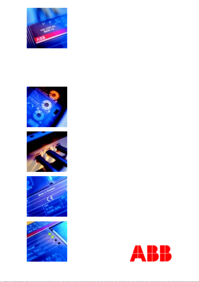
Note that in this handbook we will focus on asynchronous motors only.
Drive shaft
Stator windings
Terminal box
Cooling fan
N-endD-end
Stator
Rotor
Page 10
Squirrel cage motors
In this book the focus has been placed on the
squirrel cage motor, the most common type of
motor on the market. It is relatively cheap and
the maintenance cost is normally low. There are
many different manufacturers represented on the
market, selling at various prices. Not all motors
have the same performance and quality as for
example motors from ABB. High efficiency
enables significant savings in energy costs during
the motor’s normal endurance. The low level of
noise is something else that is of interest today,
as is the ability to withstand severe environments.
There are also other parameters that differ.
The design of the rotor affects the starting current
and torque and the variation can be really large
between different manufacturers for the same
power rating. When using a softstarter it is
good if the motor has a high starting torque at
Direct-on-line (D.O.L) start. When these motors
are used together with a softstarter it is possible to
reduce the starting current further when compared
to motors with low starting torque. The number
of poles also affects the technical data. A motor
with two poles often has a lower starting torque
than motors with four or more poles.
About Motors
3
I
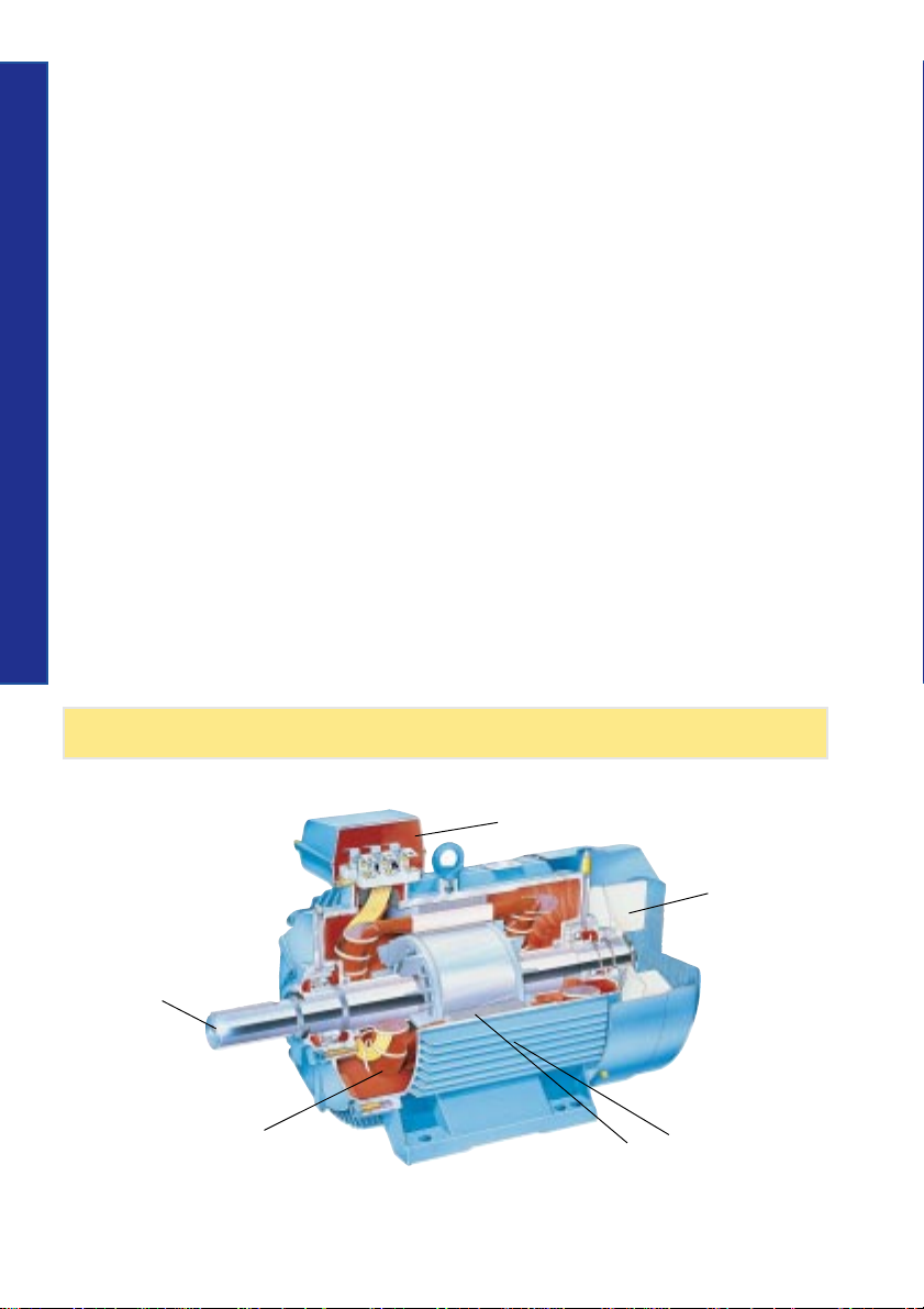
Current diagram for typical sqirrel cage motor
Max. starting current
Rated current
rpm
T
Starting torque
Torque diagram for a typical squirrel cage motor
Max. torque
Rated torque
rpm
Page 11
Voltage
Three-phase single speed motors can normally
be connected for two different voltage levels.
The three stator windings are connected in star
(Y) or delta (D).
The windings can also be connected in series or
About Motors
parallel, Y or YY for instance. If the rating plate
on a squirrel cage motor indicates voltages for
both the star and delta connection, it is possible
to use the motor for both 230 V, and 400 V as an
example.
The winding is delta connected at 230 V and if
the main voltage is 400 V, the Y-connection is
used.
When changing the main voltage it is important
to remember that for the same power rating the
rated motor current will change depending on the
voltage level.
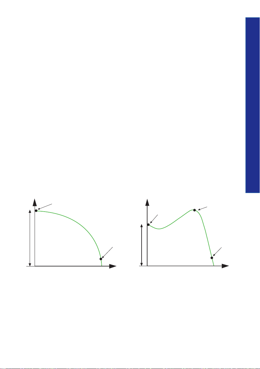
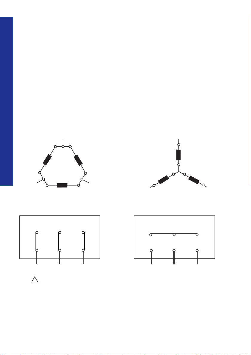
The method for connecting the motor to the
terminal blocks for star or delta connection is
shown in the picture below.
W2
4
W1
L3
V2 V1
– Connection
230 V
(400 V)
Wiring diagram for Y- and Delta connection
L1
W1U1 V1
U1
L1
U1
U2
W2
V2
V1
L2
V2W2 U2
U2
L2
L3
W1
V2W2 U2
W1U1 V1
L3L1 L2
L3L1 L2
Y – Connection
400 V
(690 V)
Page 12

Power factor
A motor always consumes active power, which it
converts into mechanical action. Reactive power
is also required for the magnetisation of the motor
but it doesn’t perform any action. In the diagram
below the active and reactive power is represented
by P and Q, which together give the power S.
The ratio between the active power (kW) and the
reactive power (kVA) is known as the power
factor, and is often designated as the cos ϕ. A
normal value is between 0.7 and 0.9, when
running where the lower value is for small motors
and the higher for large ones.
About Motors
P
ϕ
Q
Diagram indicating P, Q, S and Cos ϕ
S
5
Page 13
Speed
The speed of an AC motor depends on two things:
the number of poles of the stator winding and
the main frequency. At 50 Hz, a motor will run
at a speed related to a constant of 6000 divided
by the number of poles and for a 60 Hz motor
the constant is 7200 rpm.
About Motors
To calculate the speed of a motor, the following
formula can be used:
2 x f x 60
n =
p
n = speed
f = net frequency
p = number of poles
Example:
4-pole motor running at 50 Hz
2 x 50 x 60
n =
6
This speed is the synchronous speed and a
squirrel-cage or a slip-ring motor can never
reach it. At unloaded condition the speed will
be very close to synchronous speed and will
then drop when the motor is loaded.
4
= 1500 rpm
The difference between the synchronous and
asynchronous speed also named rated speed is
”the slip” and it is possible to calculate this by
using the following formula:
n1 - n
s =
n
1
s = slip (a normal value is between 1 and 3 %)
n1 = synchronous speed
n = asynchronous speed (rated speed)
Table for synchronous speed at different
number of poles and frequency:
No. of poles 50 Hz 60 Hz
2 3000 3600
4 1500 1800
6 1000 1200
8 750 900
10 600 720
12 500 600
16 375 450
20 300 360
T
Diagram showing syncronous speed vs.rated speed
Rated speed
Syncronous
speed
}
rpm
Slip
Page 14
Torque
The starting torque for a motor differs significantly
depending on the size of the motor. A small
motor, e.g. ≤ 30 kW, normally has a value of
between 2.5 and 3 times the rated torque, and
for a medium size motor, say up to 250 kW, a
typical value is between 2 to 2.5 times the rated
torque. Really big motors have a tendency to have
a very low starting torque, sometimes even lower
than the rated torque. It is not possible to start
such a motor fully loaded not even at D.O.L
start.
The rated torque of a motor can be calculated
using the following formula:
9550 x P
=
M
r
Mr = Rated torque (Nm)
Pr = Rated motor power (kW)
nr = Rated motor speed (rpm)
r
n
r
Slip-ring motors
In some cases when a D.O.L start is not permitted
due to the high starting current, or when starting
with a star-delta starter will give too low starting
torque, a slip-ring motor is used. The motor is
started by changing the rotor resistance and when
speeding up the resistance is gradually removed
until the rated speed is achieved and the motor
is working at the equivalent rate of a standard
squirrel-cage motor.
The advantage of a slip-ring motor is that the
starting current will be lower and it is possible to
adjust the starting torque up to the maximum
torque.
In general, if a softstarter is going to be used for
this application you also need to replace the motor.
T
About Motors
7
T
Tst/Tn1.5...2.5
Torque diagram for a typical squirrel cage motor
rpm
rpm
Torque diagram for a slip-ring motor
I
T
n
rpm
Current diagram for a slip-ring motor
Page 15
Different starting methods
The following is a short description of the most common starting methods for
squirrel cage motors.
An overview of common problems when starting and stopping a motor with different
starting methods, see page 14
Direct-on-line start (D.O.L)
Different starting methods
8
Start-delta start
Frequency converter
Softstarter
Page 16
Direct-on-line start (D.O.L)
This is by far the most common starting method
available on the market. The starting equipment
consists of only a main contactor and thermal or
electronic overload relay. The disadvantage with
this method is that it gives the highest possible
starting current. A normal value is between 6 to 7
times the rated motor current but values of up to
9 or 10 times the rated current exist. Besides the
starting current there also exists a current peak
that can rise up to 14 times the rated current
since the motor is not energised from the the first
moment when starting.
The values are dependent on the design and size
of the motor, but in general, a smaller motor
gives higher values than a larger one.
During a direct-on-line start, the starting torque
is also very high, and is higher than necessary for
most applications. The torque is the same as the
force, and an unnecessary high force gives
unnecessary high stresses on couplings and the
driven application. Naturally, there are cases
where this starting method works perfectly and
in some cases also the only starting method that
works.
Different starting methods
D.O.L. starter with contactor
and O/L relay
KM 1 Main contactor
FR 1 Overload relay
KM 1
FR 1
M
Single line diagram
for a D.O.L.
T
Starting torque
Torque/speed curve att D.O.L start
I
Current curve at D.O.L start
Max. starting current
Max. torque
9
Rated torque
rpm
Rated current
rpm
Page 17

Star-delta start
This is a starting method that reduces the starting
current and starting torque. The device normally
consists of three contactors, an overload relay and
a timer for setting the time in the star-position
(starting position). The motor must be delta
connected during a normal run, in order to be
able to use this starting method.
The received starting current is about 30 % of
the starting current during direct on line start and
the starting torque is reduced to about 25 % of
the torque available at a D.O.L start. This starting
method only works when the application is light
Different starting methods
loaded during the start. If the motor is too heavily
loaded, there will not be enough torque to
10
accelerate the motor up to speed before switching
over to the delta position.
When starting up pumps and fans for example,
the load torque is low at the beginning of the
start and increases with the square of the speed.
When reaching approx. 80-85 % of the motor
rated speed the load torque is equal to the motor
torque and the acceleration ceases. To reach the
rated speed, a switch over to delta position is
necessary, and this will very often result in high
transmission and current peaks. In some cases the
current peak can reach a value that is even bigger
than for a D.O.L start. Applications with a load
torque higher than 50 % of the motor rated torque
will not be able to start using the start-delta starter.
Page 18
KM 2
KM 3 KM 1
400 V
Different starting methods
230 V
KM 1 Main contactor
KM 2 Delta contactor
KM 3 Star contactor
FR 1 Overload relay
T
FR 1
FR 1
I
KM 1
KM 3KM 2
M
Single line diagram for a Star-delta starterStar-delta starter with contactors and O/L relay
11
rpm
Torque/speed curve at Star-Delta start Current curve at Star-Delta start
rpm
Page 19
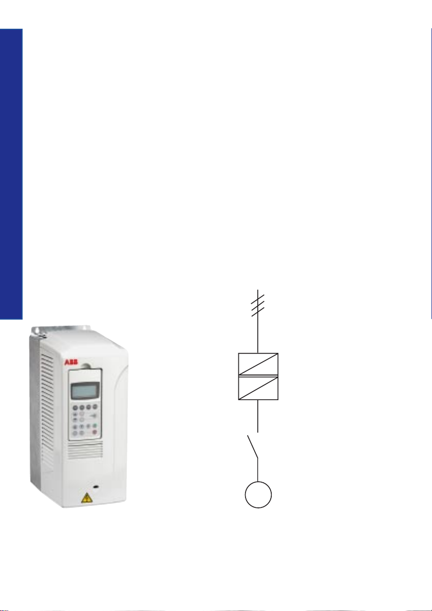
Frequency converter
The frequency converter is sometimes also
called VSD (Variable Speed Drive), VFD
(Variable Frequency Drive) or simply Drives,
which is probably the most common name.
The drive consists primarily of two parts, one
which converts AC (50 or 60 Hz) to DC and the
second part which converts the DC back to AC,
but now with a variable frequency of 0-250 Hz.
As the speed of the motor depends on the
frequency this makes it possible to control the speed
of the motor by changing the output frequency
from the drive and this is a big advantage if there
Different starting methods
is a need for speed regulation during a continuous
run.
In many applications a drive is still only used
for starting and stopping the motor, despite the
12
fact that there is no need for speed regulation
during a normal run. Of course this will create a
need for much more expensive starting equipment
than necessary.
By controlling the frequency, the rated motor
torque is available at a low speed and the starting
current is low, between 1 and 1.5 times the rated
motor current. Another available feature is softstop,
which is very useful, for example when stopping
pumps where the problem is water hammering
in the pipe systems at direct stop. The softstop
function is also useful when stopping conveyor
belts from transporting fragile material that can
be damaged when the belts stop too quickly.
It is very common to install a filter together with
the drive in order to reduce the levels of emission
and harmonics generated.
KM 1 Main contactor
Q 1 Frequency converter
AC
DC
Q 1
DC
AC
Frequency converter
KM 1
M
Single line diagram for a frequency converter
Page 20
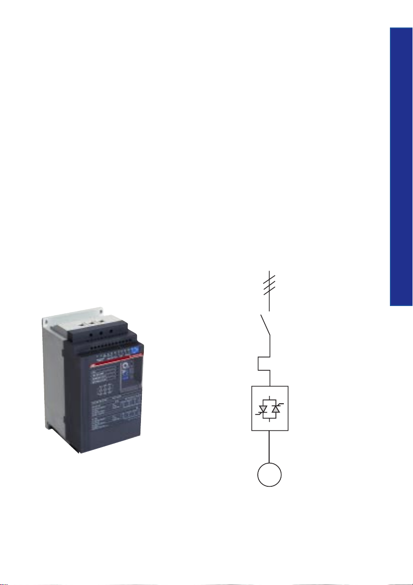
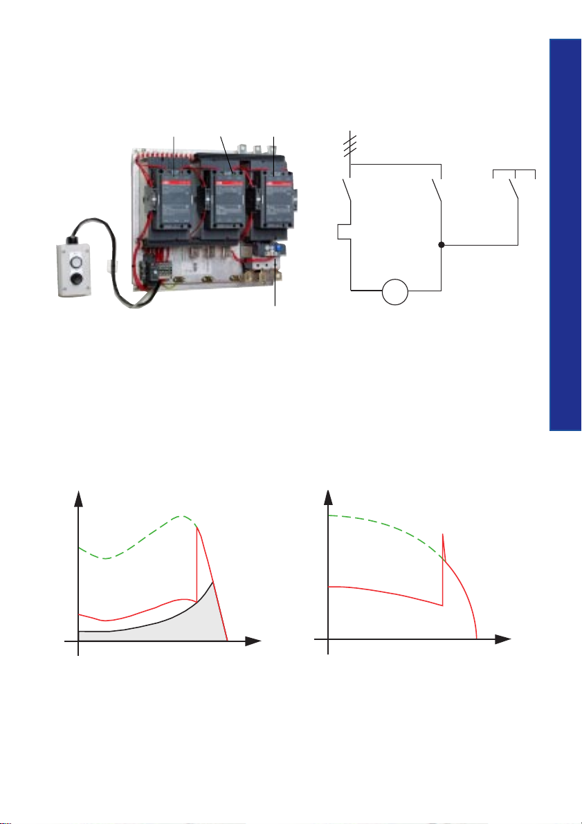
Softstarter
A softstarter has different characteristics to the
other starting methods. It has thyristors in the
main circuit, and the motor voltage is regulated
with a printed circuit board. The softstarter makes
use of the fact that when the motor voltage is low
during start, the starting current and starting
torque is also low.
During the first part of the start the voltage to
the motor is so low that it is only able to adjust
the play between the gear wheels or stretching
driving belts or chains etc. In other words,
eliminating unnecessary jerks during the start.
Gradually, the voltage and the torque increase
so that the machinery starts to accelerate.
One of the benefits with this starting method is
the possibility to adjust the torque to the exact
need, whether the application is loaded or not. In
principle the full starting torque is available, but
with the big difference that the starting procedure
is much more forgiving to the driven machinery,
with lower maintenance costs as a result.
Another feature of the softstarter is the softstop
function, which is very useful when stopping
pumps where the problem is water hammering
in the pipe system at direct stop as for star-delta
starter and direct-on-line starter.
The softstop function can also be used when
stopping conveyor belts to prevent material
from damage when the belts stop too quickly.
Different starting methods
13
Softstarter
KM 1
FR 1
Q 1
KM 1 Main contactor
FR 1 Overload relay
Q 1 Softstarter
M
Single line diagram for a softstarter
Page 21

Common problems when starting and stopping motors with
different starting methods
Type of problem Type of starting method
Direct-on-line Star-delta start Drives Softstarter
Slipping belts and Yes Medium No No
heavy wear on bearings
High inrush current Yes No No No
Heavy wear and tear Yes Yes No No
Different starting methods
on gear boxes (loaded start)
Damaged goods / Yes Yes No No
products during stop
14
Water hammering in pipe Yes Yes Best Reduced
system when stopping solution
Transmission peaks Yes Yes No No
Auto transformer start and start of a part winding motor have similar problems to the star-delta start.
Page 22
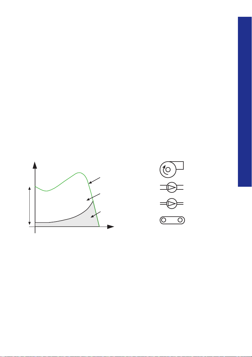
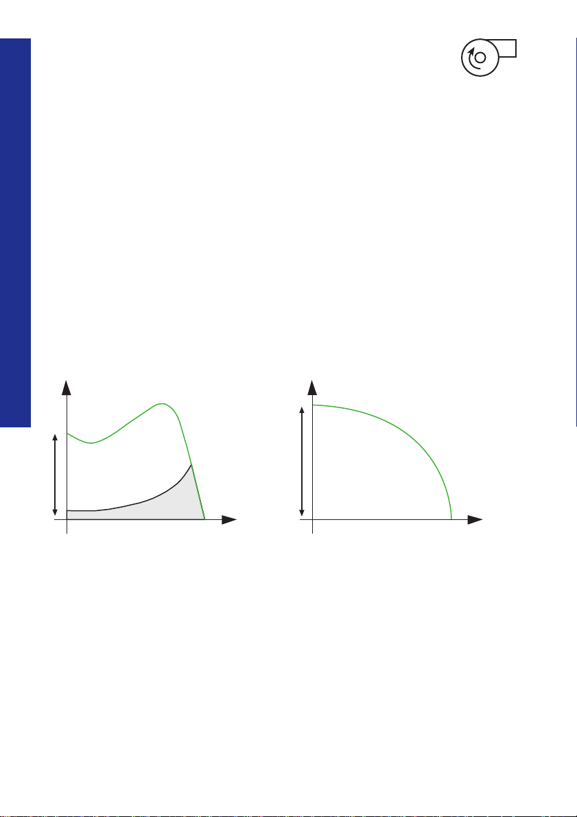
Different applications
All motors are used for starting and running different applications. This chapter
covers the most common ones. The different applications will also result in different
load conditions for the motor. There are two factors to consider:
1. Braking load torque, a direct braking force on the motor shaft. To be able to
accelerate, the motor has to be stronger than the load. The accelerating torque
is the difference between the available motor torque and the load toque.
Accelerating torque = Available motor torque – load torque
2. Involved moment of inertia or flywheel mass will also affect the start.
The bigger inertia the longer starting time for the same motor.
T
Available
motor torque
Accelerating
torque
Braking load
(load torque)
rpm
Centrifugal fan
Centrifugal pump
Compressor
Conveyor belt
Different applications
15
Page 23
Centrifugal fan
For some applications the motor is started with reduced load torque, i.e. unloaded
start. Big centrifugal fans are often started with a closed damper and this will make
the start easier (shorter) but since the moment of inertia is still present the starting
time might be quite long anyway.
Direct-on-line start
Centrifugal fans are very often driven by one or
more drive belts. During a D.O.L start these belts
have a tendency to slip. The reason is that these
Different applications
types of fans always have a more or less high
moment of inertia (big flywheel). So even if the
fan is started unloaded, the flywheel is still there.
1616
T
rpm
Torque/speed curve at D.O.L start Current curve at D.O.L start
The belts slip depending on whether the starting
torque from the motor is too high during the
start sequence and the belts are not able to
transfer these forces. This typical problem gives
high maintenance costs but also production
losses when you need to stop production to
change belts and bearings.
I
rpm
Page 24
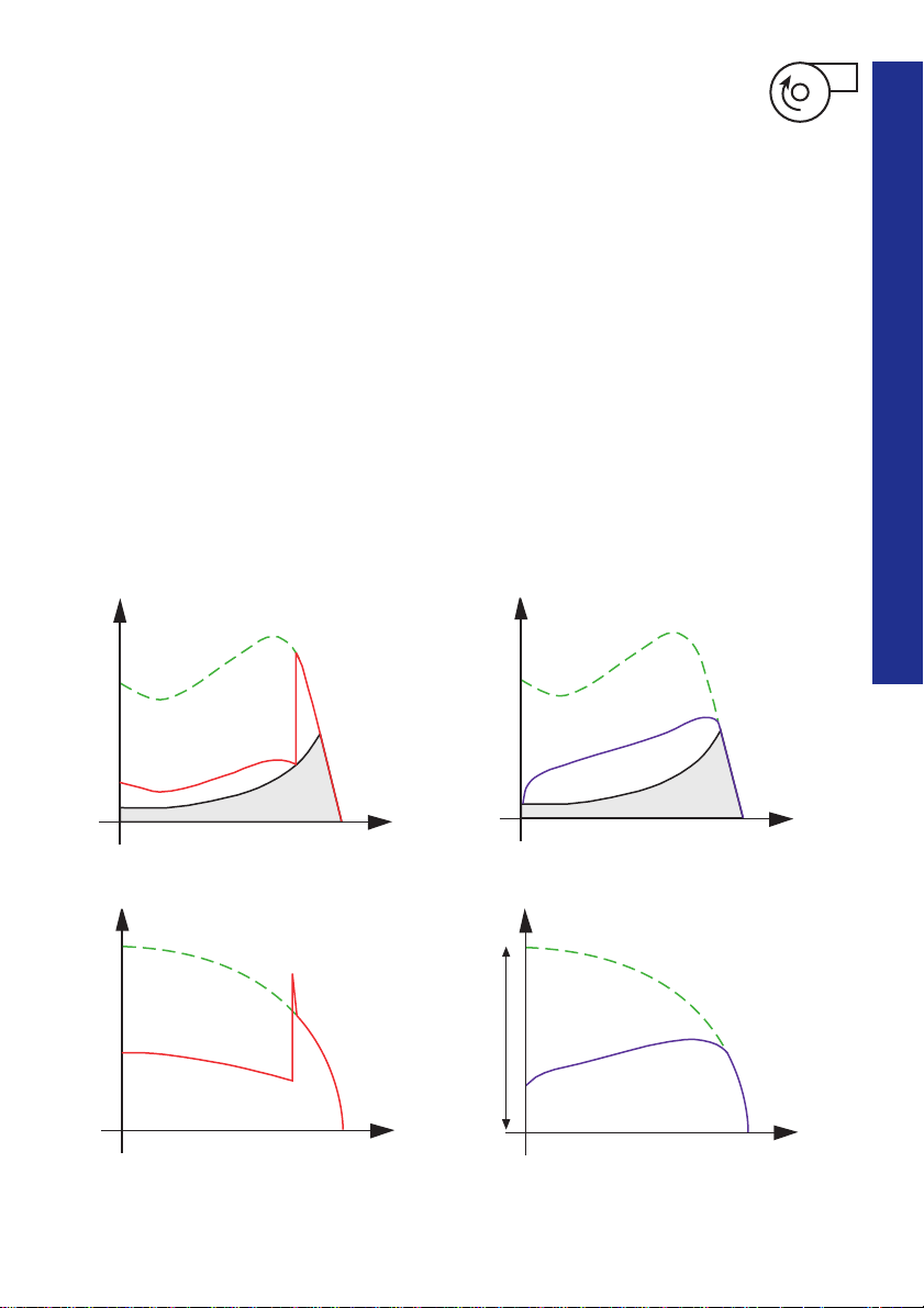
Star-delta starter (Y-D)
The star-delta starter gives lower starting torque
but depending on the fact that the load torque
increases with the square of the speed, the motor
torque will not be high enough in the star position
to accelerate the fan to the rated speed.
When switching over to delta position it will
be both a high transmission and current peak,
often equal to values when making a D.O.L start
or even higher, with a slipping belt as a result.
It is possible to reduce the slip by stretching the
belts very hard. This gives high mechanical
stresses on bearings both in the motor and the
fan with high maintenance costs as result.
Softstarter
Different applications
The key to solve these problems is to reduce the
starting torque from the motor during start.
By using an ABB softstarter the voltage is
decreased to a low value at the beginning of the
start, low enough to avoid slip but high enough
to start up the fan. The softstarter provides the
ability to adjust to fit any starting condition, both
unloaded and fully loaded starts.
T
Torque/speed curve at Star-Delta start
I
Current curve at Star-Delta start
rpm
rpm
T
17
rpm
Torque/speed curve when using a softstarter
I
rpm
Current curve when using a softstarter
Page 25
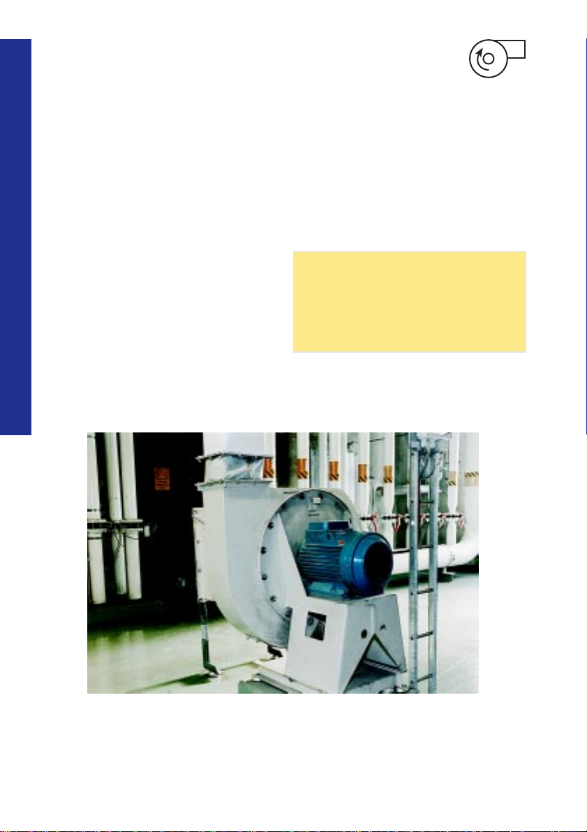
Selection of a suitable
softstarter
Normal start
For fans with small or medium large flywheels,
select a softstarter according to the rated motor
power.
The above is valid if the time for D.O.L start
is less than 5 seconds.
Heavy duty start
For fans with large flywheels, select a softstarter
Different applications
designed for heavy duty start according to the
rated motor power. It is also possible to select a
softstarter for normal start, select a unit with one
size bigger power rating than the motor and use
an overload relay class 30.
The above is valid if the time for D.O.L start
is more than 5 seconds.
1818
Recommended basic settings:
Start ramp: 10 sec.
Stop ramp: 0 sec.
Initial voltage: 30 %
Current limit is recommended for use.
Application with a centrifugal fan
Page 26
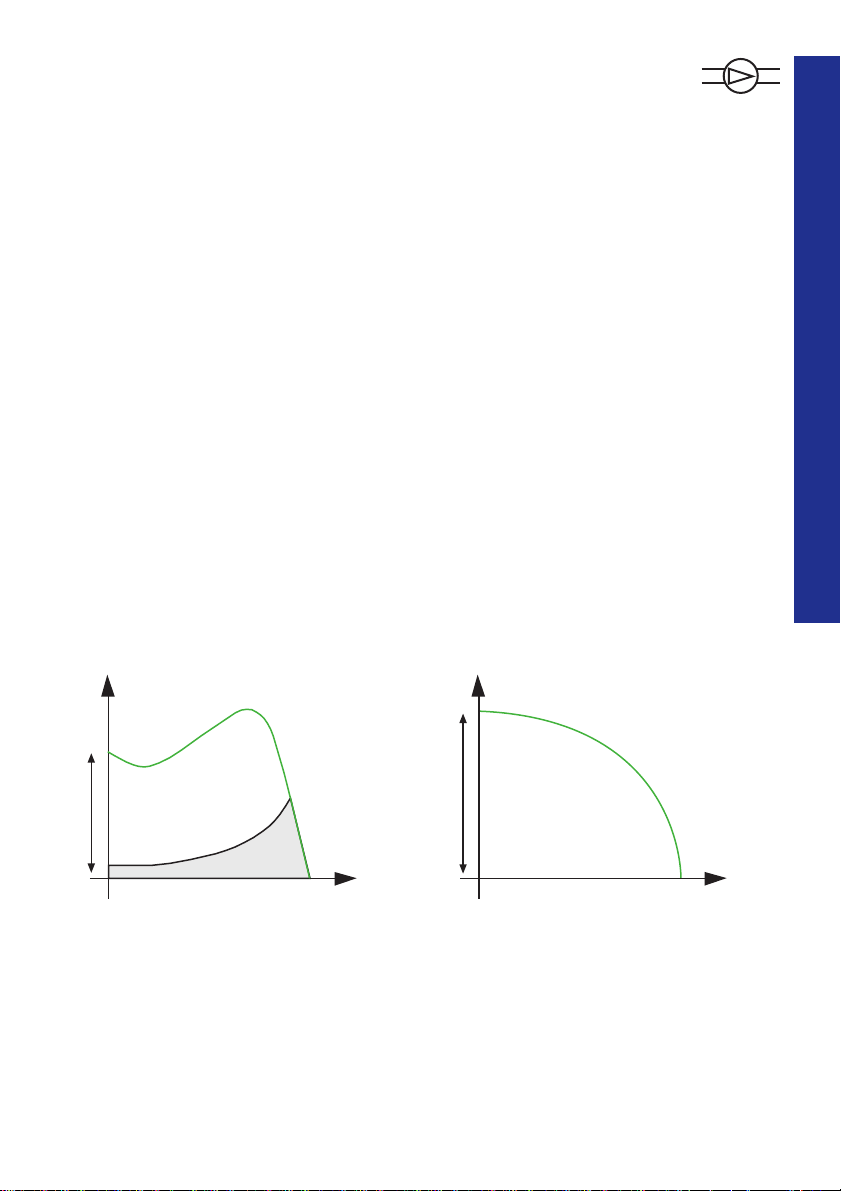
Centrifugal pump
There are a lot of different types of pumps; like piston pumps, centrifugal pumps,
screw pumps etc. But the most common version is the centrifugal pump and we
have selected this one to describe.
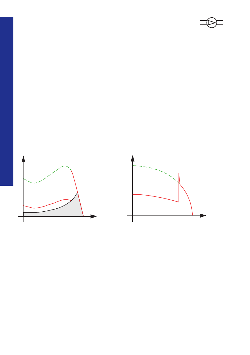
Direct-on-line start
Starting up a pump is normally not a problem
for a squirrel cage motor. The problem is the
wear and tear depending on pressure waves in
the pipe system created when the motor starts
and stops too quickly. During a D.O.L start the
motor gives much too high starting torque
with the result that the motor accelerates and
reaches nominal speed too quickly. The reason
is that the braking load torque is low for a pump
during start. This starting method also gives
maximum possible starting current.
T
I
Different applications
19
Torque/speed curve at D.O.L start
rpm
rpm
Current curve at D.O.L start
Page 27
Star-delta starter (Y-D)
When stopping a pump
By using a star-delta starter it is possible to
reduce the starting torque. The motor torque
in the star position is too weak to be able to
complete the start and reach the rated speed.
The quadratic load torque will become too high
for the motor when reaching approx. 80-85 % of
the rated speed and the switch over to the delta
position will give both high transmission and
current peaks with pressure waves as a result.
Different applications
The current peaks can be equally high as at a
D.O.L start or even higher.
T
During stop it is also normal to have problems.
When making a direct stop by disconnecting
the main supply the motor stops too quickly.
Depending on high mass flow in the pipe system
the water will continue with the same speed for
a short period and then come back again,
backwards in the pipe system. This creates high
pressure shocks on valves and gives high
mechanical stresses on the pipe system.
I
2020
rpm
Torque/speed curve at Star-Delta start Current curve at Star-Delta start
rpm
Page 28
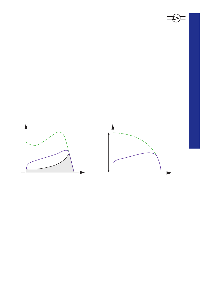
Softstarter
By using an ABB softstarter the voltage is reduced
during the start sequence with the result that the
motor torque is reduced. During the start
sequence the softstarter increases the voltage so
that the motor will be strong enough to accelerate
the pump to the nominal speed without any
torque or current peaks. A normal starting
current with a softstarter when starting a fully
loaded centrifugal pump is approx. 4 times rated
motor current.
Also during the stop sequence the softstarter is
the solution. The softstarter reduces the voltage
during stop via a voltage ramp and the motor
becomes weaker and weaker. Because of this the
water speed slows down very smoothly without
creating any pressure waves.
A special function on the softstarter is sometimes
available, called "step-down voltage",which ensures
an optimum setting to the actual need for any
pipe system.
Different applications
T
rpm
Torque/speed curve when using a softstarter Current curve when using a softstarter
I
21
rpm
Page 29
Selection of a suitable
softstarter
Normal start
Starting a pump is a typical normal start
condition.
Select a softstarter according to the rated
motor power.
Heavy duty start
Not applicable for this application.
Different applications
2222
Recommended basic settings:
Start ramp: 10 sec.
Stop ramp: 20 sec.
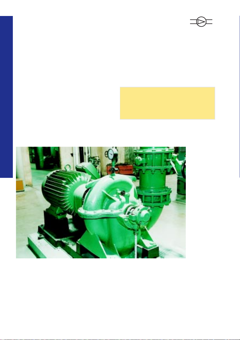
Initial voltage: 30 %
Application with a pump.
Page 30

Compressor
Smaller compressors are often of piston type and the load torque increases linearly
with the speed. Screw compressors are often used when there is a bigger need for air
flow and this type has a load torque increasing with the square of the speed.
Drive belts are often used between motor and compressor but direct connections via
some type of toothed couplings are also common. Some compressors are started with
reduced load.
Direct-on-line start (D.O.L)
Compressors started direct-on-line are exposed
to high mechanical stresses on the compressor
itself, but also on drive belts and couplings. The
result is shortened endurance. In cases where the
T
drive belts are used the belts very often slip
during start. The high starting torque received
during starting with this method is the source
of the problems. The starting current is always
high at D.O.L start. A normal value can be
approx. 7 times rated motor current.
I
Different applications
23
Torque/speed curve at D.O.L start
rpm
rpm
Current curve at D.O.L start
Page 31

Star-delta starter (Y-D)
Star-delta start gives a lower starting torque and
starting current but the motor is too weak during
the start up to be able to accelerate the motor
up to nominal speed. When switching to the
delta position both current and torque peaks
Different applications
will occur with high mechanical stresses as a
result. Compressors are very often running at
no load condition for longer periods when the
pressure in the system is high. A motor running
under these circumstances always has a poor
power factor and low efficiency. Some times the
value is so low that it must be compensated.
T
I
2424
rpm
Torque/speed curve at Star-delta start Current curve at Star-delta start
rpm
Page 32

Softstarter
By using an ABB softstarter it is possible to
limit the starting torque to a level suitable for
all different applications. The result is less stress
on couplings, bearings and no slipping belts
during start. The maintenance cost will be
reduced to a minimum. When using a softstarter
the starting current received is approx. 3 to 4
times the rated motor current.
Different applications
T
rpm
Torque/speed curve when using a softstarter Current curve when using a softstarter
I
25
rpm
Page 33

Selection of a suitable
softstarter
Normal start
For compressors with D.O.L starting time less
than 5 seconds, select a softstarter according to
the rated motor power.
Heavy duty start
For compressors with D.O.L starting time more
than 5 seconds, select a softstarter designed for
heavy duty start according to the rated motor
Different applications
power.
It is also possible to select a softstarter for
normal start, select a unit with one size bigger
power rating than the motor and use an overload
relay class 30.
2626
Recommended basic settings:
Start ramp: 10 sec.
Stop ramp: 0 sec.
Initial voltage: 30 % (piston compressor)
40 % (screw compressor)
Application with a compressor
Page 34

Conveyor belt
Conveyor belts can have a lot of different looks and directions of use. It is a typical
constant torque load with low to high braking torque depending on how heavy it is loaded.
Direct-on-line start (D.O.L)
Conveyor belts often need a starting torque very
near or just above the rated torque of the motor.
A direct-on-line start with a normal squirrel cage
motor gives approx. 1.5 to 2.5 times rated torque
of the motor depending on motor size, type etc.
When making a direct-on-line start there is a
very high risk of slipping between the belt and
Low braking torque
T
the driving role depending on this high starting
torque.
Gearboxes and couplings are also exposed to high
mechanical stresses. This result is considerable
wear and tear and often high maintenance costs.
Sometimes fluid couplings are used to reduce the
transferred torque. This method is expensive and
requires a lot of maintenance.
High braking torque
T
Different applications
27
Torque/speed curve at D.O.L start
I
Current curve at D.O.L start
rpm
rpm
Torque/speed curve at D.O.L start
rpm
I
rpm
Current curve at D.O.L start
Page 35

Star-delta start
It is not possible to use this starting method
when the load torque is close to the rated motor
torque during start (see figure below, High
braking torque).
Different applications
Low braking torque High braking torque
T
T
2828
rpm
Torque/speed curve at Star-delta start Torque/speed curve at Star-delta start
I
rpm
I
Current curve at Star-delta startCurrent curve at Star-delta start
rpm
rpm
Page 36

Softstarter
Different applications
By using an ABB softstarter the starting torque
can be reduced to a minimum value still able to
start up the conveyor belt. The setting possibility
of the softstarter makes it possible to adjust the
torque to exactly the level that is necessary for
the start. The result is the least possible stress on
T
rpm
Torque/speed curve when using a softstarter
gearboxes and couplings and no slipping belts
during start. This will reduce the maintenance
cost to a minimum. When using a softstarter
you will receive approx. 3 to 4 times rated motor
current during start.
High braking torqueLow braking torque
T
29
rpm
Torque/speed curve when using a softstarter
I
Current curve when using a softstarter
rpm
I
rpm
Current curve when using a softstarter
Page 37

Selection of a suitable
softstarter
Normal start
A start of short and light loaded conveyor belt is a
typical normal start.
For conveyors with D.O.L starting time less
than 5 seconds, select a softstarter according to
the rated motor power.
Heavy duty start
Conveyor belts can in some cases be very long and
Different applications
if the belt is fully loaded during start the starting
time can be very long. For such applications select
a softstarter designed for heavy duty start. It is also
possible to select a softstarter for normal start if
the softstarter is chosen one size larger than the
rated motor power and use an overload relay
class 30.
3030
Recommended basic settings:
Start ramp: 10 sec.
Stop ramp: 0 sec.
(If fragile material use 10 seconds)
Initial voltage: 40 %
Application with a conveyor belt
Page 38

How to select a softstarter for
different applications
It is normally possible to select a softstarter according to the rated motor power. In
some cases it is neccessary to select a larger softstarter than the rated motor power
depending on the starting conditions (heavy duty start, many starts/h etc.) The
starting capacity of a softstarter is very much depending on the thyristor capacity and
the heat sink.
The table below can be used as a guide to select a softstarter if you need a quick
answer and you want to be sure that the size is large enough to suit the application.
This selection will not give the most optimized solution.
If an opimised solution is required, the software selection program ”ProSoft”
for selection of softstarters can be used, available on www.abb.com/lowvoltage.
Quick guide
How to select a softstarter
Normal start
Typical applications
Bow thruster »Centrifugal pump
»
»Compressor »Conveyor belt (short)
»Elevator »Escalator
Selection
Select the softstarter according to the
rated motor power.
For units with built-in overload, select
trip class 10.
Select one size larger than the selection above.
If more than 6 starts /h
Heavy duty start
Typical applications
Centrifugal fan »Conveyor belt (long)
»
»Crusher »Mill
»Mixer »Stirrer
Selection
For softstarters designed for nomal start,
select one size larger than the rated motor
power.
For softstarters designed for heavy duty
start, select according to the rated motor
power.
For units with built-in overload, select trip
class 30.
31
Page 39

32
Page 40

Description of the softstarters
- Design, settings and signals
A softstarter in general is built up with a few main components such as a printed
circuit board (PCB), heat sink, thyristors, fans and housing (plastic or metal).
The controlling circuits can be of digital type, analogue type or a combination of
these. The output signal relays can be of a type with fixed function or as a free
programmable type where the user can decide upon the output function.
The softstarter is sometimes equipped with a built-in electronic overload relay
(EOL) replacing the conventional bi-metal relay which is normally used.
A built in EOL has much better accuracy than a conventional relay, since the values
are calculated electronically and this is especially useful when on intermittent duty.
The need for communication between different devices in a plant and from the
devices to a control board is increasing all the time. Many of today’s softstarters are
equipped with a port for such communication, which normally consists of a few
fibre optic cables instead of former solutions, which often reqired hundreds of
thousands of wires. Many different communication protocols exist today and some
of them are more common than others, for example Modbus, Profibus, DeviceNet,
Interbus-S, LON Works and so on.
Description of the softstarter
33
Page 41

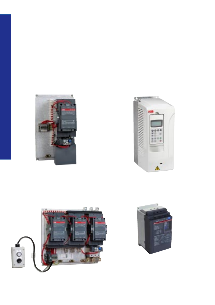
Description of different components:
Housing
Printed circuit board
Description of components
34
Thyristor
Housing
Main terminals
Heat sink
Fan
Page 42

Printed circuit board is used to
control the firing of the thyristors based on the
current and voltage references, and also for the
calculation of different values, for example the
power factor, active power, etc. It can also be
used for storing historical data, the event log,
indicating trends and much more.
Heat sink is used to get rid of the heat in
the softstarter generated by the current during
the start and the continuous run. The capacity
of the heat sink very much reflects the starting
capacity and the operational current of the
softstarter.
Fans are used to increase the cooling
capacity of the heat sink. One, two or several
fans can be used depending on size and design.
Some smaller softstarters don’t have fans at all
and the number of starts may be limited.
Zero crosses
Housing can be made of plastic material,
Description of components
metal or a combination of these, and its function
is to protect the inside components from
mechanical and electrical damage. It is also used
to protect the components from dust and dirt.
For total outside protection from dust and dirt
a separate enclosure is often required since the
degree of protection (IP class) of the unit itself
is too low.
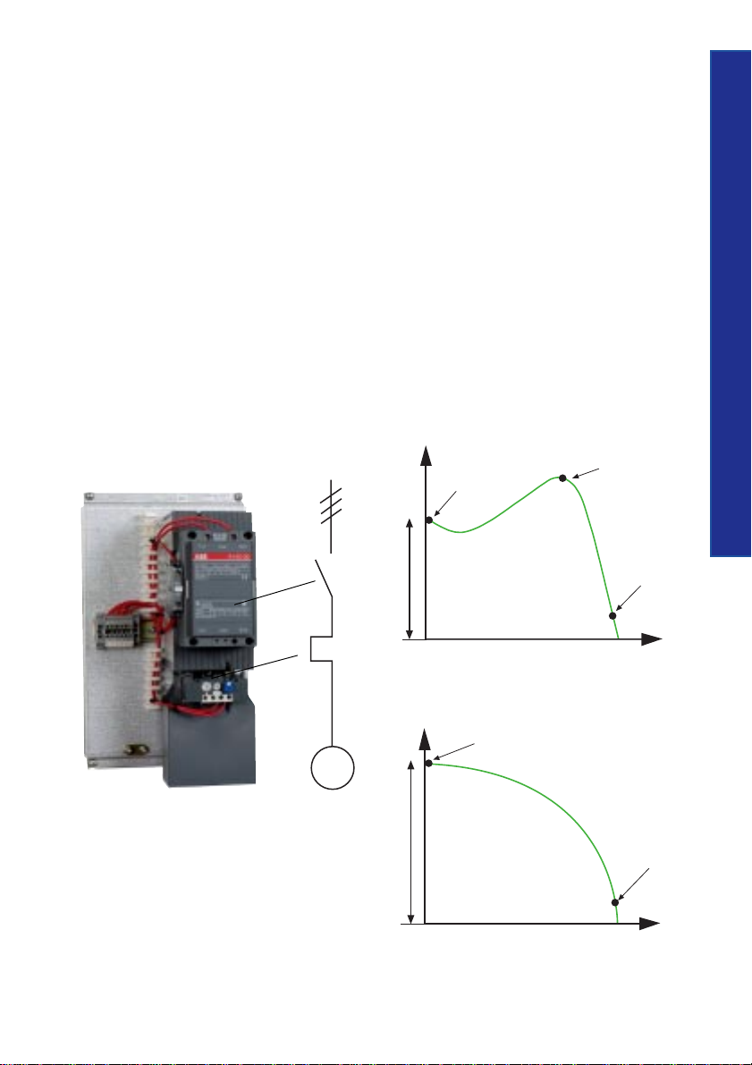
Thyristors are semi-conducting
components connected in an anti-parallel fasion
and placed in two or three phases of the main
circuit. They regulate (by increasing or decreasing) the level of voltage during start and the
stop ramp, as described in the picture below.
During a continuous run the thyristors are
conducting fully.
35
Firing angle
Start: The thyristors let part of the voltage through at the beginning and
then increase it, according to the set ramp time for the start.
Stop: The thyristors are fully conducting and when soft stopping, they
decrease the voltage according to the set ramp time for stop.
Off : Thyristor is non-conducting
On : Thyristor is conducting
Page 43

Common settings
This section includes a short description of some common setting parameters
available on most of the softstarters. Other settings may be available depending
on the type of softstarter and manufacturer. The setting can be done either by
adjusting potentiometers, changing dip switches, using a key pad, a computer or
similar.
Start ramp is the time from were the
Common settings
softstarter start its ramp (initial voltage) until
full voltage is reached. The ramp time should
not be too long, as this will only result in
unnecessary heating of the motor and a risk
of the overload relay to trip. If the motor is
unloaded the start time for the motor will
probably become shorter than the set ramp
time, and if the motor is heavily loaded, the
start time will probably become longer.
Stop ramp is used when a soft stopping
36
of the motor is required, for example a pump
or a conveyor belt. The stop ramp is the time
from full voltage until stop voltage (initial
voltage) is reached. If the ramp time is set to
zero the stop will be like a direct stop.
U
e
Initial voltage
(U
)
ini
Initial voltage. Sometimes named
pedestrian voltage or torque, this is the point
from where the softstarter starts or stops its ramps.
The torque of the motor will drop with the
square of the voltage and if the voltage is set
too low, for example 20 %, the starting torque
will become 0.22 = 0.04 = 4 % only, and the
motor will not start from the very beginning.
Therefore it is very important to find a level
that is just high enough to make the motor take
off directly to avoid unnecessary heating.
Start ramp Stop ramp
Diagram showing start ramp, stop ramp and initial voltage
Time
Page 44

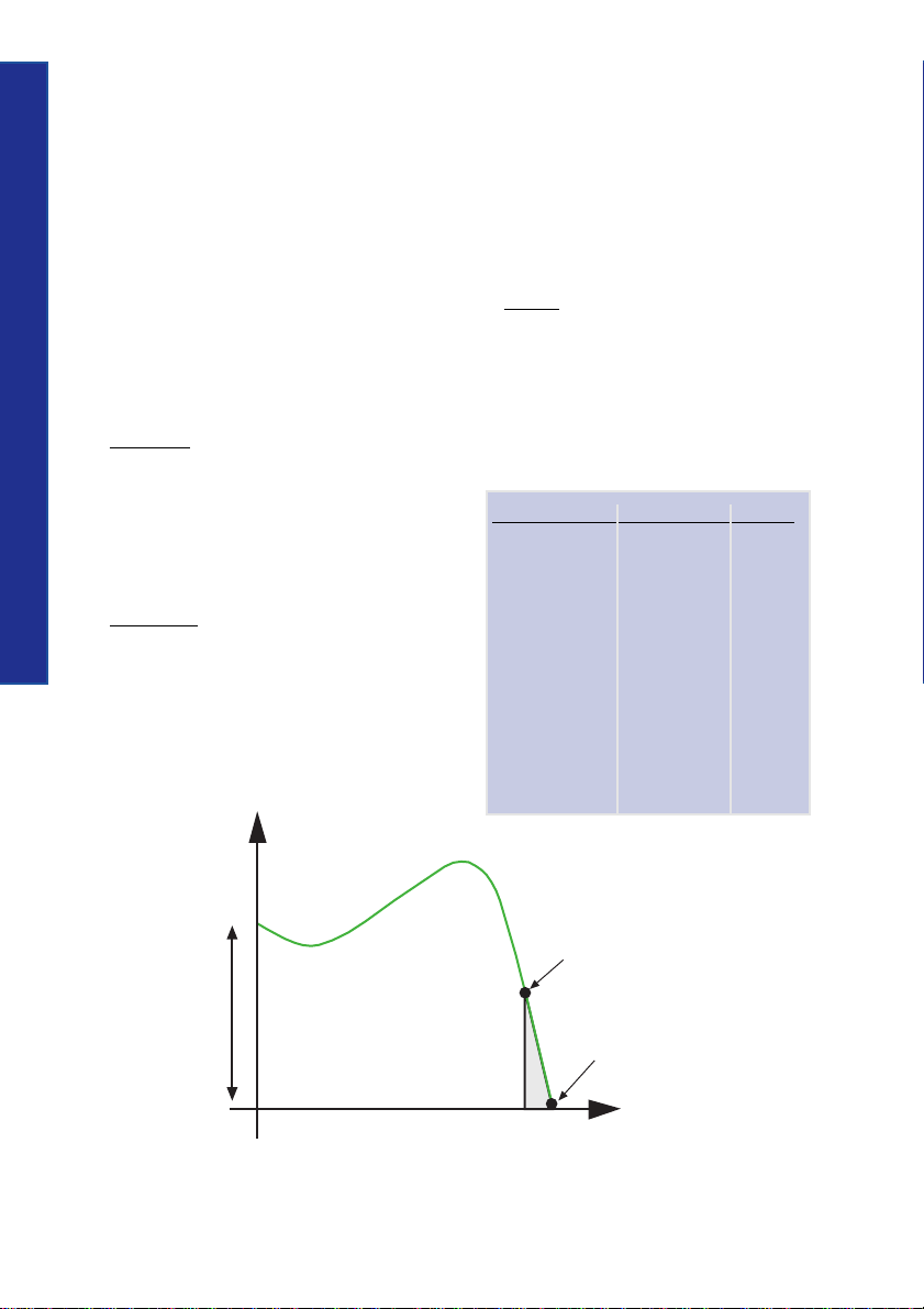
Current limit can be used in applications
where a limited starting current is required, or
at a heavy-duty start when it is difficult to
achieve a perfect start with the setting of the
initial voltage and the start ramp only. When
the current limit is reached, the softstarter will
temporarily stop increasing the voltage until the
current drops below the set limit, and then
continues ramping up to full voltage.
Note that this feature is not available on
all softstarters.
U
100 %
fixed voltage
30 %
Common settings
reached set level
of current limit
37
1
t
t1 + t2 = set ramp time
I
5
2
Current limit function in softstarter use
2
t
set level of
current limit
Time
Time
Page 45

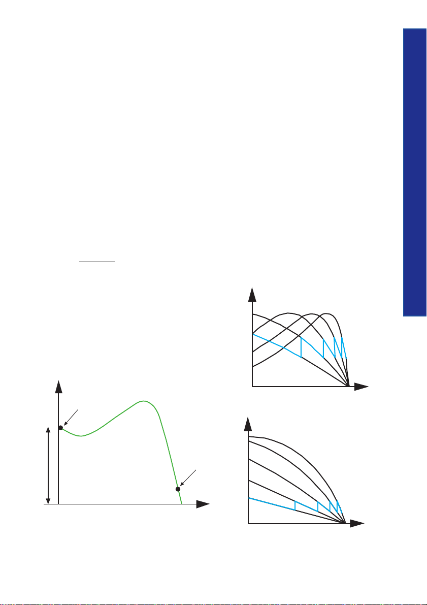
Step down voltage gives a special
type of stop ramp. It is possible to adjust the
voltage to drop to a level where the speed of
the motor starts to reduce immediately at the
stop command. For low loaded motors the
speed will not reduce until a very low voltage
is reached, but using the step down voltage
function can eliminate this phenomenon and
is especially useful for stopping pumps.
Common settings
Adjustable rated motor
current makes it possible to set the motor
rated current on the softstarter for the used motor.
This setting may affect other values as well, such
as the trip level of the electronic overload relay,
the level of the current limit function and so on.
38
Step down voltage = U
U
100 %
Example 50 %
30 %
Curve showing the step down voltage function
SD
Initial voltage 30 %
(= end voltage 30 %)
Stop Time
Page 46

Different indications
The indications on a softstarter differ very much from one type to another and also between
manufacturers. Some of the most common indications are described below.
Different indications
On normally indicates that the power supply
is connected to the softstarter and that the unit
is ready to start the motor.
Top of Ramp indicates that the start
ramp is completed and full voltage is reached.
If a by-pass contactor is used it will be activated
at this point.
Fault indication can be of many different
types. One is if there is an internal fault on the
softstarter itself, a fault on the feeding side (phase
loss, blown fuse or similar) or on the motor side
(motor not connected, phase missing etc.)
Overload indicates that the overload
protection has tripped. The reason for a tripping
overload can be too high motor current, too long
starting time, too many starts after each other,
wrong set overload, wrong trip class of overload
or a combination of these.
Overtemperature indicates that the
softstarter unit is over-heated, due to the number
of starts exceeded, too high-rated current, too
long starting time or similar.
39
Page 47

Different voltages
Different named voltages are used for the softstarters. The name and use of these
different voltages is stated in the IEC-standard as below.
Main Voltage (Ue),
which is the voltage feeding the motor and
also the voltage exposed to the main circuit
(thyristors) in the softstarter. 200 - 690 V
Different voltages
are normal values.
Supply voltage (Us),
which is the voltage feeding the electronic
components inside the softstarter, for example
the printed circuit board.
Common values are 110 - 120 V or 220 - 240 V.
40
Internal
supply
Main Voltage (Ue)
L1
L3
L2
Start
Stop
T1
T2
Power
supply
T3
M
Main voltage and supply voltage to a softstarter
Supply
Voltage (Us)
Control Voltage (Uc),
which is the voltage for controlling the start
and stop command of the softstarter.
Values between 24 - 480 V exist.
Main Voltage (Ue)
L1
L3
L2
Control
Voltage (Uc)
Start
Stop
T1
T2
Power
supply
T3
(Internal
power
supply)
M
Main voltage and control voltage to a softstarter
Page 48

Ambient temperature
The ambient temperature is the average
surrounding temperature of the softstarter over a
period of 24 hours. For most types of softstarter
the temperature may not exceed 40 oC without
derating the operational current for the unit.
The maximum ambient temperature during
operation differs from one type of softstarter
to another and must be checked individually
according to the manufacturer’s specification.
When using an ABB softstarter with an
ambient temperature of above 40 oC, the
following formula can be used to calculate
the operational current:
Ie derated = I
Ie derated = maximum operational current
I
e
- (∆ T x I
e
after derating
= rated current of the softstarter
x 0.008)
e
∆ T = temperature difference
0.008 = derating factor
Example 1
Rated current: 105 A
Ambient temperature: 48 oC
Derating with 0.8 % per oC above 40 oC
(PS S 18...300)
∆ T = 48-40
New current = I
105 - (8 x 105 x 0.008) = 98,2 A
Example 2
Rated current: 300 A
Ambient temperature: 46 oC
Derating with 0.8 % per oC above 40 oC
(PS S 18...300)
∆ T = 46-40
New current = I
300 - (6 x 300 x 0.008) = 285.6 A
o
C = 8 oC
- (∆ T x I
e
o
C = 6 oC
- (∆ T x I
e
x 0.008) =
e
x 0.008) =
e
Ambient temperature
41
Page 49

Derating when used at high
altitudes
When a softstarter is used at high altitudes the
rated current for the unit has to be derated, due
High altitudes
to less cooling. For most manufacturers the
catalogue values are valid up to 1000 m above
sea level before derating is necessary.
In some cases a larger softstarter is required to
be able to cope with the motor current when
used at high altitudes.
For ABB softstarters the following formula
can be used for calculating the derating:
x - 1000
% of I
100 %
90 %
150
e
42
% of Ie = 100 -
x = actual altitude for the softstarter
Example:
Softstarter with rated current 300 A used at
2500 meter above sea level.
1500
2500 - 1000
150
= 90
=
% of Ie = 100 -
= 100 -
150
Ie = 300 x 0.9 = 270 A
The diagram below can also be used for
defining the derating of the softstarter.
80 %
1000
Derating of motor current at high altitudes
2000
meter above sea level
3000
4000 m
Page 50

Start of several motors
M
M
In some applications, more than one motor will be started with one softstarter,
in parallel with each other or in a sequence. This is often possible to do but some
data has to be taken into consideration.
Parallel start of motors
If a softstarter is going to be used for starting
several motors at the same time (parallel start),
there are two important parameters to check:
1. The softstarter must be able to cope with
the rated current for all motors together.
2. The softstarter must be able to cope with
the starting current for all motors together
until rated speed is achieved.
Note! If a by-pass contactor is used for
the softstarter, only point 2 above has
to be taken into consideration.
Example:
Start of two motors with I
relative starting current 4 x Ie.
Starting time is 10 seconds.
Total starting current is 100 x 4 x 2 = 800 A
over 10 seconds.
Check the softstarter starting capacity graph to
verify the selected size.
= 100 A and
e
KM 1
FR 1
Q 1
Parallel start of motors using a softstarter
KM 1 Main contactor
FR 1 Overload relay
Q 1 Softstarter
Start of several motors
43
Page 51

Sequential start of motors
If a softstarter is going to be used for starting
several motors one by one (sequential start), it
is important to check that the softstarter is able
to cope with the starting current for each motor
during the whole starting sequence.
Example:
Start of three motors with Ie=100 A and
relative starting current 4 x Ie.
Starting time for the motors is:
Start of several motors
Motor 1 = 5 seconds
Motor 2 = 10 seconds
Motor 3 = 8 seconds
44
The starting current for the motors is 100 x 4 =
400 A and the total starting time is 5 + 10 + 8 =
23 seconds.
Check the softstarter starting capacity graph
to verify the selected size.
Note! It is not possible to add the starting
time for each motor if the rated current
is different from one motor to another. A
separate calculation has to be made for
those applications.
KM 1 Main contactor
K 25, 27, 29 Starting contactor
K 26, 26, 30 Run contactor
FR 1, 2, 3 Overload relay
Q 1 Softstarter
KM 1
Q 1
K 25 K 27 K 29
K 26
FR 1 FR 2 FR 3
MM
Sequential start of motors using a softstarter
K 28 K 30
M
Page 52

Different ways of connecting the
softstarter
There are two different ways of connecting the softstarter - In line, which is the
most common method, and Inside Delta. Note that only a few types of softstarters
can actually be connected Inside Delta for example the ABB softstarter range
PS S 18/30...300/515.
Different ways of connecting
45
In line Inside Delta
Page 53

In-line connection
This is easily the most common way to connect
the softstarter.
All three phases are connected in a series with
the overload relay, the main contactor and other
devices used just like the diagram below.
The selected devices for Inline connection must
be chosen to cope with the rated motor current.
Example: 100 A motor requires a 100 A
softstarter, 100 A main contactor etc.
Different ways of connecting
46
100 A
100 A
100 A
Inside Delta connection
The Inside Delta connection makes it possible
to place the softstarter in the delta circuit and
in that way it can easily replace an existing
Y/D-starter.
When the softstarter is Inside Delta it will
only be exposed to 58 % (1/√3) of the In-line
current. Therefore it is possible to downsize the
devices in order to achieve a more cost-effective
solution.
Example: A 100 A motor requires a 58 A
softstarter, a 58 A main contactor if placed in
the delta circuit, etc.
A motor used for an Inside Delta connection
must be able to delta-connect during a continuous
run. In the USA and some other countries a
special six-wire motor has to be ordered for this
type of connection.
100 A
100 A
M
100 A
Softstarter connected In-line with the motor
58 A
58 A
58 A
M
100 A
Softstarter connected Inside Delta
Page 54

Location of the main contactor
B
M
x
When using the softstarter Inside Delta there
are two options for the main contactor: in the
delta circuit or outside. Both locations will stop
the motor but in alternative A, the motor is still
considered to be under tension.
In alternative B the main contactor must be
chosen according to the rated current of the
motor, while the contactor in alternative A can
be chosen according to 58 % (1/√3) of the
rated current.
x
Different ways of connecting
47
Alternative A
Main contactor located in the delta circuit
M
A
Alternative B
Main contactor located outside the delta circuit
Page 55

48
Page 56

Basic settings
for
different
applications
The required settings for the softstarter will differ from one application to another
depending on the type of load, motor characteristics, how much the motor is
loaded, etc.
For a more in depth description of each setting, please see chapter ”Description
of the softstarters”.
Note ! All settings on next page are only proposals and may change from one application
to another and therefore need to be checked individually.
Basic settings
49
Page 57

Settings when using a softstarter without current limit function
Type of load Ramp time for Ramp time Initial voltage
Basic settings
Bow thruster 10 0 30 %
Centrifugal fan 10 0 30 %
Centrifugal pump 10 20 30 %
Centrifuge 10 0 40 %
Conveyor belt 10 0
Crusher 10 0 60 %
Escalator 10 0 30 %
50
Heat pump 10 20 30 %
Hydraulic pump 10 0 30 %
Lifting equipment 10 10 60 %
Mill 10 0 60 %
Piston compressor 10 0 30 %
Rotary converter 10 0 30 %
Scraper 10 10 40 %
Screw compressor 10 0 40 %
Screw conveyor 10 10 40 %
Stirrer, Mixer 10 0 60 %
Unloaded motor 10 0 30 %
start (sec.) for stop (sec.) U
1)
ini
40 %
1) If fragile material, use 10 seconds.
Page 58

Settings when using a softstarter with current limit function
Type of load Ramp time for Ramp time Initial voltage Current limit
start (sec.) for stop (sec.) Uini ( x Ie)
Bow thruster 10 0 30 % 3
Centrifugal fan 10 0 30 % 4
Centrifugal pump 10 20 30 % 3.5
Centrifuge 10 0 40 % 4.5
Conveyor belt 10 0
Crusher 10 0 60 % 5
Escalator 10 0 30 % 3.5
Heat pump 10 20 30 % 3.5
Hydraulic pump 10 0 30 % 3.5
Lifting equipment 10 10 60 % 4
Mill 10 0 60 % 5
Piston compressor 10 0 30 % 4
Rotary converter 10 0 30 % 3
Scraper 10 10 40 % 4.5
Screw compressor 10 0 40 % 4
Screw conveyor 10 10 40 % 4
Stirrer, Mixer 10 0 60 % 5
Unloaded motor 10 0 30 % 2.5
1)
40 % 4
Basic settings
51
1) If fragile material, use 10 seconds.
Page 59

Starting capacity and overload
protection
Starting capacity for softstarters
When starting a squirrel cage motor there will
Starting capacity
always be a starting current (Ist) which is
higher than the rated motor current.
The starting current depends on what type of
starting method is used and in some cases also
the size of the motor, particular at D.O.L-start.
For a softstarter a normal value is 3-4 times the
rated motor current.
52
Time
Sec.
1000
100
Heavy duty applications normally require
a starting current between 4 and 5 times the
rated motor current.
The maximum permitted starting current for
a softstarter depends on the starting time. The
ratio between the current and time is displayed
in the graph below.
A higher starting current will give a shorter
possible starting time, for example a crusher
application. A lower current will allow a longer
starting time, for example a pump application.
10
1
100
Typical starting capacty graph for a softstarter
200
300 400
A
Starting
current
Page 60

Starting capacity when using
by-pass contactor
Starting capacity when using
Starting capacity
overload protection
When using a softstarter with a by-pass contactor
it is sometimes possible to select a softstarter with
a lower rated power than the motor rated power
since the softstarter will be working during start
and stop only, not continuously.
The softstarter can not withstand the rated
motor current and therefore a check of the starting capacity must be carried out for the selected
size.
Time
b
a
The overload protection for the motor (thermal
or electronic) will very often set the limit of the
starting capacity. A class 10 relay is used for
normal starts in general while a class 30 relay is
used for heavy-duty starts where a longer starting time must be used.
In some applications where the overload
protection is by-passed (other protection active)
during a start to achieve a longer available
starting time, it is particularly important to
check the softstarter starting capacity since this
will be the limitation.
53
Starting
a) Tripping curve for overload protection
b) Max starting capacity for a softstarter (This will limit the starting time / current if the overload is
by-passed during start)
current
Page 61

Number of starts/hour
The maximum number of starts/hour for a softstarter depends on several different
factors such as the starting current, ambient temperature, starting time and the
intermittens factor.
Intermittens factor
The intermittens factor is a figure indicating
how long the softstarter has been running
for (starting time and running time) compared
with the total cycle time.
It is important to define the intermittens
Number of starts/hour
factor when talking about the number of starts/
hour since the OFF time is the cooling time for
the softstarter.
A high starting current and a long starting time
require a longer OFF time than a low starting
current and short time to maintain the same
number of starts/hour.
54
I
ntermittens factor =
Duty cycle
On
Examples:
If a softstarter has been running for 5 minutes
of a total duty cycle of 10 minutes then the
intermittens factor is 50 % ON time and 50 %
OFF time.
If a softstarter has been running for 45
minutes of a duty cycle of 60 minutes then
the intermittens factor is 75 % ON time and
25 % OFF time.
Off
on
on + off
x 100 %
Time
Page 62

Harmonics
Harmonics are unwanted voltages and currents existing in almost every electrical
system today and are always a multiple of the rated frequency.
Typical harmonics are 3rd, 5th, 7th, 9th etc. The harmonics contribute to the
unnecessary heating of motors, cables and other equipment and may shorten the
lifetime of these devices if exposed for a long period of time.
It can sometimes also disturb functions on electronics and systems. The harmonic
contents and the level naturally depends on the source but also on several other
parameters such as the impedance in the feeding network, the motor, capacitors and
other devices used in the system altogether - in other words a quite complex
phenomenon.
Harmonic content and
softstarters
The question of harmonic content for softstarter
applications is actually in general not relevant
at all. These reflections usually come from
drive applications where harmonics are generated
continuously and a filter is always required in
public networks and very often used also in
industrial networks. With our softstarters we
fulfil the EMC directive concerning emission
and immunity and there is no need for any
particular actions regarding this matter at all.
Harmonics
55
55
Page 63

Explosive atmospheres (Ex)
For plants in environments where the hazard of explosion is due to an explosive
mixture of gases, explosive matter or combustible dust other than explosive dust,
special provisions are applicable regarding the use of electrical material. For electrical
motors there are two main principles for explosion protection. One is to design
the motor so that no sparks or dangerous heat occurs. The other method is to isolate
sparks and dangerous heat inside the motor to prevent ignition of any explosive
mixture of gases outside the motor.
The different classes of explosive protection (Ex) are described by the following parts of
IEC 60079:
Explosive atmospheres
IEC 600079-1: flameproof enclosures ”d”
IEC 600079-2: pressurised enclosures ”p”
IEC 600079-5: powder filling ”q”
IEC 600079-6: oil immersion ”o”
IEC 600079-7: increased safety ”e”
56
IEC 600079-11: intrinsic safety ”i”
IEC 600079-18: encapsulation ”m”
IEC 600079-22: caplights for mines susceptible to firedamp (under consideration)
Example: Electrical apparatus for explosive atmospheres - oil immersion ”o” shall be recognised as Exo.
Page 64

Hazardous areas and zones
The hazardous areas are categorised in
zones as follows:
Zone 0
An area in which an explosive gas atmosphere is
present continuously or for long periods. Only
intrinsically-safe circuits of category Exi may be
used in this zone. Motors are thus excluded.
Zone 1
An area in which an explosive gas atmosphere is
likely to occur in normal operation. Motors of
category Exd, Exe and Exp may be used in this
zone.
Zone 2
An area in which an explosive gas atmosphere is
not likely to occur during normal operation and
if it does occur it will exist for a short period
only. Equipment permitted in zones 0 and 1
may of course be used. Under certain conditions
the equipment, motors for instance, need not to
be of explosion-protected design.
3 m
r4.5 m
Location and selection
of softstarter for Ex
environments
If a softstarter is going to be used for an Ex
application it is normally located in a separate
enclosure outside any of the hazardous zones.
The overload relay used shall be of a special
version designed for EEx motors, for example
TA 25 DU...V 1000 to T 900 DU/SU...V 1000.
This type of relay has a more accurate tripping
curve compared with the standard relay. Special
attention has to be paid to this.
The softstarter type and size and other devices
used in the circuit shall suitably be selected
according to type 2 co-ordination.
Note !
If any electrical equipment is going to be
used in any of the hazardous zones a special
enclosure must be used. This type of
enclosure (steel box or similar) must be
able to withstand an inside explosion
caused by any of the components without
letting anything out to the surroundings.
This solution is in general very unusual.
Explosive atmospheres
57
57
3 m
Low point
Zone 0
Example of classification and extent of the hazardous area in a tank
Zone 1
Zone 2
To wall
Surface of liquid
Height
of wall
Page 65

Co-ordination
By co-ordination we mean a selected combination of electrical apparatus which is
safe for the surroundings and personnel, even if an overload or a fault should occur
in the system.
The co-ordinated group must ensure the following four essential functions:
• Protection against overloads. A protection, which guards all components, cables
Co-ordination
58
and the motor from overheating, active for all currents up to, locked rotor current.
This device will send a trip signal to a disconnection mean, which is normally a
contactor used for the motor control.
• Motor control. This function is commonly carried out by a contactor.
• Protection against short-circuits, which takes care of all currents above the locked
rotor current - i.e. all fault currents.
• Isolation. Ensure an isolating air-gap when opened for personnel safety.
The co-ordinations for the ABB softstarters are done according to IEC 60947-4-2
”AC semiconductor motor controllers and starters” and EN 60947-4-2.
The provisions of IEC 60947-1, General Rules, are applicable to IEC 60947-4-2
where specifically called for.
Page 66

Types of co-ordination
The standard IEC 60947-4-2 defines two types
of co-ordination according to the expected level
of service continuity. The standard IEC 60947-1,
General Rule are applicable to this standard,
where specifically called for.
Type 1:
Co-ordination requires that, under short-circuit
conditions, the device shall cause no danger to
persons or installation and may not be suitable
for further service without repair and replacement
of parts.
Type 2:
Co-ordination requires that, under short-circuit
conditions, the device shall cause no danger to
persons or installation and shall be suitable for
further use. For hybrid controllers and starters,
the risk of contact welding is recognized, in
which case the manufacturer shall indicate the
measures to be taken as regards the maintenance
of the equipment.
Note !
When using a softstarter in a type 2
co-ordination, replacing the fuses and
restart has to be accepted after a shortcircuit. Only semi-conductor fuses can
be used to achieve a type 2 co-ordination
for a softstarter.
Co-ordination
59
59
Page 67

Utilization Categories
Some utilization categories are stated in the standard IEC 60947-4-2, ”AC semiconductor
motor controllers and starters”. The one used for ABB Low Voltage softstarters is AC-53.
Co-ordination
Utilization Typical application
Category
AC-52a Control of slip-ring motor stators: 8 h duty with on-load currents for
start, acceleration, run
AC-52b Control of slip-ring motor stators: intermittent duty
AC-53a Control of squirrel cage motors: 8 h duty with on-load currents for
60
AC-53b Control of squirrel cage motors: intermittent duty
AC-58a Control of hermetic refrigerant compressor motors with automatic resetting of
AC-58b Control of hermetic refrigerant compressor motors with automatic resetting of
start, acceleration, run
overload releases: 8 h duty with on-load currents for start, acceleration, run
overload releases: intermittent duty
Remarks
AC-53 is the utilization category used for softstarters in general since this is about
controlling squirrel cage motors. This is the category stated in the header of the
co-ordination tables for softstarters.
AC-53a is about softstarter designed for use without by-pass contactor.
AC-53b is about softstarter designed for use with by-pass contactor.
Page 68

Types of fuses
There are basically three types of fuses used on the market (see below) with different
functions and characteristics. One type of fuse cannot in general replace another
type without checking the other protection devices in the circuit since the protection
characteristic of the fuse is different between the types. If replacing a 100 A fuse with
another 100 A fuse (same rating) without checking the type there is a risk of losing
protection since the first type may be of type with both short-circuit protection and
thermal protection while the replacement fuse is only short-circuit protection.
gL/gG fuses have a combination of short circuit
protection and thermal overload protection
(5s > 3,5 x In) for cables.
If using these types of fuses together with a
softstarter, type 1 co-ordination can be achieved.
For type 2 co-ordination semi-conductor fuses
must be used.
aM fuses have only a short-circuit protection
(5s > 9 x In), and for thermal overload
protection a separate protection device is
required.
If using these types of fuses together with a
softstarter, type 1 co-ordination can be achieved.
For type 2 co-ordination semi-conductor fuses
must be used.
Semi-conductor fuses (High speed fuses) are
the only type of fuses that are fast enough to
achieve a fully type 2 co-ordination when
using a softstarter. A separate overload relay
for the motor protection is always required
in combination with this type of fuse. If
replacing the semi-conductor fuses with an
MCCB, MMS or similar, type 1 co-ordination
will be achieved instead.
Time
a
c
b
d
a: Characteristic of the overload relay
b: Characteristic of a gL/gG fuse
c: Characteristic of a semi-conductor fuse
d: Area where the gL/gG fuse is not fast enough
to achieve a type 2 co-ordination
Current
Co-ordination
61
61
Page 69

Where to find the co-ordination tables
The co-ordination tables for softstarters can be found on internet page www.abb.com
under Low Voltage Products - Product Coordination.
When selecting the wanted product type, for example softstarters the table below
will show up.
Co-ordination
Ue Main voltage for the application
Iq Short-circuit current rating
Coor. Type Type of co-ordination
Starting type Type of start, normal or heavy duty
SCPD type Type of protection device
Size kW Rated motor power range
62
Table Name of the co-ordination table (click on the text to open)
Last Update Latest date of table update
Example of starter range, Ue= 400 - 500 V.
Page 70

How to read the co-ordination tables
In the header of the selected table, information about softstarter type, main voltage, shortcircuit rating, maximum ambient temperature, IEC-standard and co-ordination type can be
found.
Motor Indicates the rated output of the motor and maximum current.
If this does not correspond fully to the actual motor, select according
to the maximum current.
Softstarter Indicates suitable softstarter type and size for this motor.
Semi-conductor fuses Indicates rated current and type of semi-conductor fuse.
Switch fuse Indicates suitable switch fuse for the semi-conductor fuses.
Thermal overload relay Indicates suitable thermal overload relay, type and setting range.
Co-ordination
Line contactor Indicates suitable line (main) contactor for the motor.
This contactor is given with AC-3 rating.
By-pass contactor Indicates suitable by-pass contactor which is not required for the
co-ordination. This contactor is given with AC-1 rating.
Example of co-ordination table: 500V, 65kA, normal start, type 2 (PSD5065LINE40)
63
63
Page 71

Starter and fuses In-line Starter Inside Delta and
fuses In-line
The co-ordinations with the devices In-line are
based on this circuit diagram.
Note that the by-pass contactor is not
Co-ordination
required for the co-ordination.
64
Softstarter
Switch fuse
Semi-conductor fuse
Line contactor
O/L relay
By-pass
contactor
The co-ordinations with the softstarter Inside
Delta are based on this circuit diagram.
Note that the by-pass contactor is not
required for the co-ordination.
Switch Fuse
Semi-conductor fuse
Softstarter
By-pass
contactor
Motor
Line contactor
O/L relay
M
Starter and fuses In-line
Line contactor AC-3
By-pass contactor AC-1
Motor
M
Starter inside delta and fuses In-line
Line contactor AC-3
By-pass contactor AC-1
Line contactor and by-pass contactor Inside Delta
connected
Page 72

ESD – Electro Static Discharge
An increasing problem today with the use of more and more electronic equipment in
our systems is the Electro Static Discharge (ESD). The main source of the problem is
the wrong handling of electronic components, printed circuit-boards, etc. A component
damaged by ESD has been exposed to a too high voltage level and today the components
are much more sensitive depending on integration, which means more functions in
the same capsule. The distances between the conductors are decreased and therefore
the insulation distance will be at a minimum. A value of 0.002 mm is common in
modern integrated circuits.
Electro static charge is caused in three different ways:
• Rubbing of two surfaces to each other.
• Separation of two surfaces from each other, for example when removing a plastic cover from its contents.
• Induction caused by static electricity without any contact of the material.
Two type of faults and
different circuits
The ESD damages are divided into two groups
of faults: direct fault and latent defect. The direct
faults are quite easy to detect since the component
will not work at all and this is very often discovered
at the factory before shipping.
The latent defects can be very difficult to
identify since the component is not working in
a reliable way and the life length of the device
may be reduced dramatically.
Fault generated by ESD
Digital circuits:
• ”Ones” becomes ”zeros” and ”zeros”
becomes ”ones” for no reason.
• No ”ones” or ”zeros” at all ( the circuit is dead).
Analogue circuits:
• Worsening accuracy of measuring
• Wrong voltage levels that require adjustments
• Malfunction
Printed Circuit Board (PCB)
ESD - Electro Static Discharge
65
65
Page 73

Electro static voltage levels
A voltage level of between 100-500 V can
destroy any electronic components in principle.
The most sensitive components can only withstand voltages between 25-170 V.
Sometimes it is possible to hear a ”click”
sound when touching an object and that is
typical ESD phenomena. When it is possible to
hear that ”click” sound the voltage level is already
at least 3,5 kV. Sometimes it is also possible to
see a spark when touching an object and the
voltage level is then at least 10 kV.
Below some values are given for typical Electro
static charge:
ESD - Electro Static Discharge
Walking on a wall-to-wall carpet: 10 - 20 kV
Walking on a plastic floor (PVC): 2 - 5 kV
66
Walking on an anti-static floor: 0 - 2 kV
Lifting paper from a table: 5 - 35 kV
Rising from a chair: 10 -25 kV
Protection against ESD
damages
It is possible to reduce the risk of ESD to a
minimum for the equipment. This is very
important to remember when making service
and/or repair with electronic components for
example the printed circuit board on a softstarter.
Actions to prevent damages:
• Avoid charge if possible
• Always use a wrist strap or similar
connected to ground potential when
working with electrical components
• Always use the right type of package (ESD
protected bags, etc.)
• Connect all machines and apparatus
to ground potential
• High humidity
Page 74

Frequently asked questions (FAQ)
Main contactor
Q Is there any requirement to put a main
contactor in series before the softstarter?
A The softstarter does not require any main
contactor but we recommend the use of one
for emergency stop and/or trip of the
overload relay. In some applications an MCCB
can be used instead of the main contactor.
Ambient temperature
Q Can I use a softstarter if the ambient
temperature is higher than the recommended
value during operation?
A The softstarter can normally be operated
at a higher ambient temperature during
operation if the rated current for the unit is
derated according to the manufacturer’s
recommendation.
hyristor shorted
T
Q Is it possible to run a softstarter with one
thyristor shorted?
A Yes, it is possible but not for all types of
softstarters.
Soft stop applications
Q What applications are suitable for soft stop?
A Pumps and conveyor belts loaded with fragile
products are the two main applications
suitable for soft stop.
Advantages of by-pass
Q What are the advantages of using by-pass?
A Reduction of power loss. It is also possible
to reduce the enclosure size and use a higher
IP-class since air ventilation is not required.
Power loss
Q What is the power loss of a softstarter
during a continuous run?
A The values can normally be found in the
catalogue. For ABB softstarters the following
formula can be used (for example for
PS S 18...300):
P
= [3 x Ie x 1.0] + 50 (W) reduced to
Ltot
50 W only which is the power of the cooling
fans when using by-pass.
Ie is the operational current of the motor.
Utilisation category
Q What utilisation category should be used for
the main contactor and the by-pass contactor?
A Main contactor: always use AC-3.
By-pass contactor: it is possible to use AC-1.
Fault indication when starting
Q Why does the softstarter indicate a fault
when the start signal is given to the main
contactor and softstarter at the same time?
A If the main contactor is closed too late the
softstarter will indicate this as a phase loss
fault. Delay the start signal to the soft starter
by approx. 0.5 sec. to solve this phenomenon.
FAQ
67
67
Page 75

Test without motor
Q Can I test a softstarter without using a motor?
FAQ
A No, this is not possible since there will be no
current going through the softstarter and
some types will also indicate loss of load.
Different frequency
Q Can I use the same softstarter at both 50
and 60 Hz?
A It is possible with all type of ABB softstarters
as long as the curve is sinusoidal.
Overload relay trips during start
Q Why does the overload relay trip during start?
A Possible reasons can be one of these or in a
combination:
- too low current limit
- too long ramp time
- too low initial voltage
- wrong tripping class on the overload
- wrong setting on the overload
Separate overload relay when
68
using by-pass
Q Do I need a separate overload relay when
using a softstarter with built-in electronic
overload and by-pass?
A If the current transformers of the softstarter
can be installed so that the measuring can
be performed when by-passed a separate
relay is not required; otherwise yes.
Voltage fluctuations
Q What voltage fluctuations are allowed for
the softstarters?
A The minimum and maximum value where
we can guarantee full function is -15 % to
+10 % of the rated value. This is also stated
in the IEC-standard.
Example: 400 V - 15 % to +10 % ≥ 340 V -
440 V range.
Semi-conductor fuses
Q Do I always have to use semi-conductor fuses?
A When using semi-conductor fuses a type 2
co-ordination can be achieved.
It is possible to use an MCCB (moulded
case circuit breaker) or MMS (manual
motorstarter) instead but then with a type 1
co-ordination. For a more in-depth
description see the chapter on co-ordination.
Page 76

Environmental information
How a product affects the environment is a matter that is becoming more and more
important when designing new products today but also when updating existing product
ranges. In order to get a complete picture of all environmental aspects, there are some
different methods of doing this.
LCA
LCA (Life Cycle Assessment) is a management
tool for appraising and quantifying the entire
life cycle of particular materials, the impact of
products or activities over their total lifetime by
analysing the entire life cycle of particular
materials, processes, products, technologies,
services or activities. The most important aspects
affecting the environment for a softstarter has
proven to be:
• Choice of material in the softstarter
• Energy losses during lifetime
• Recycling possibilities
The LCA process includes the
entire lifecycle of a product
Environmental information
69
Page 77

EPD
EPD (Environmental Product Declaration) is a
document describing the environmental effects
both during manufacturing and the usage of a
specific product, for example the softstarter range
PS S 18/30...300/515. The document includes
among other things a material list indicating
kg/product used of aluminium, copper, steel,
glass, etc. and also tables for energy consumption
and losses. It is possible to see the difference
when using the softstarter In-line, Inside Delta
and/or with a by-pass contactor.
Tables for global warming potential, ozone
depletion potential, acidification potential and
so on are also included. The complete declaration
is available on www.abb.com under document
number 1SFC 288007-en.
Environmental information
Type of material kg/product kg/kW
Aluminium 2.2 0.03
Cardboard 2.4 0.03
70
Copper and copper alloys 3.1 0.04
Steel 4 0.05
Wood 0.83 0.01
Polymers 1.7 0.02
Epoxy resin 0.033 0.000
Glass 0.025 0.0003
Silicone rubber 0.0047 0.9*10
Example of a material list for a softstarter.
-4
Page 78

Industrial IT
ABB has committed, as a key element of its business strategy, to a broad program of
product development and positioning under the Industrial IT umbrella (IIT). The
main reason behind the Industrial IT certification is to make it easier and more
effective to combine products into systems and solutions.
All products that pass the Industrial IT certification tests achieve the Industrial IT
enabled sign.
Enabled products are verified for properties that make them work together in a pre-defined manner
with other enabled products in an Industrial IT environment throughout the full life cycle of the
plant. This means that IIT certified products should be easier to:
• Purchase
• Design
• Engineer
• Install
• Commission
• Operate
• Maintain
• De-install
Industrial IT
71
Page 79

Different levels
In order to acknowledge the fact that there are different requirements on integration
properties between different applications and markets, there are four levels that a
certain product can be certified for:
Industrial IT
Level 0 - Information
Level 3 - Optimisation
• Product is supplied with minimal aspect set
in prescribed formats including Product
Information, Product Classification,
Product Documentation, CAD Data and
Technical Data.
Level 1 - Connectivity
• As Information, plus.
• Hardware can be physically connected
72
via defined interfaces.
• Software is installed and handled in a
consistent way.
• Basic interoperability of the product in
the environment it is inserted in.
• Basic data can be exchanged via defined
protocols.
Level 2 - Integration
• As Connectivity, plus.
• Aspect Object Types are provided with
at least the Basic set of Aspects.
• Extended data can be exchanged via
defined protocols.
• Relevant functionality is available as
Aspect Systems on integration level 2.
• As Integration, plus.
• Aspect Object Types are provided with
at least the Extended set of Aspects.
• Relevant functionality is available as
Aspect Systems on integration level 3.
• The product is handled consistently
throughout the life cycle and value chain.
Softstarter level
All our softstarter ranges today are Industrial
IT enabled with the suite name Control
Softstarters, certifiaction level 0 - Information.
An Industrial IT enabled product can be
recognized by the Industrial IT enabled sign on
the packing.
More information and documentation is
available on www.abb.com
IT
Page 80

Formula and conversion factors
In this chapter some useful formula and conversion factors can be found.
The formulas can be used for calculating for example rated motor torque, moment
of inertia, flywheel mass, etc.
The conversion factors can be used to convert for example kW to HP, Celsius to
Fahrenheit, km/h to miles/hour, etc.
Formula
Ohm’s law
I = UR =
RI
Rated motor torque
Mr =
Moment of inertia
m(R
J =
Flywheel mass
2
mD
U
9550 x P
n
r
2
+ r2)
2
2
or GD
U = I x R
r
(mD2 ~ GD2)
I = Current (ampere)
U = Voltage (volt)
R = Resistance (ohm)
Mr = Rated torque, Nm
Pr = Rated motor power, kW
nr = Rated motor speed, rpm
J = Moment of inertia, kgm
m = Mass for the flywheel, kg
R = Outer radius, m
r = Inner radius, m
mD2 = Flywheel mass, kpm
2
GD
= Flywheel mass, kgm
2
2
2
Formula and conversion factors
73
Relation Moment of inertia and
Flywheel mass
J =
=
44
2
1 GD
1 mD
2
J = Moment of inertia, kgm
mD2 = Flywheel mass, kpm
2
GD
= Flywheel mass, kgm
2
2
2
Page 81

Moment of inertia on load shaft
recalculated to the motor shaft
M
2
n
b
b
x
n
x n
b
b
n
r
J
J´b =
Load torque on load shaft
recalculated to the motor shaft
M´b =
Formula and conversion factors
74
Electrical power
J´b= Moment of inertia recalcu lated
to the motor shaft, kgm
Jb= Moment of inertia for the load,
2
kgm
nb= Speed of the load, rpm
nr= Speed of the motor, rpm
M´b = Load torque recalculated to
the motor shaft, Nm
Mb= Load torque, Nm
nb= Speed of the load, rpm
nr= Speed of the motor, rpm
2
U x I x PF
P =
1000
U x I x PF x √2
P =
1000
U x I x PF x √3
P =
1000
P = Power in kW (1-phase)
PF = Power factor
P = Power in kW (2-phase)
P = Power in kW (3-phase)
Page 82

Quantities and units
Length
yd. = yard
m = metre
mm = millimetre
cm = centimetre
in. = inch
ft. = feet
km = kilometre
Time
h = hour
min = minute
s = second
Weight
oz. = ounce
lb. = pound
kg = kilogram
g = gram
Power / Energy
HP = horsepower
W = watt
kW = kilowatt
kWh = kilowatt-hours
Volume
l = litre
ml = millilitre
cu.in. = cubic inch
cu.ft. = cubic feet
gal. = gallon
fl.oz. = fluid ounce
Electrical
A = Ampere
V = Volt
W = Watt
Ω =Ohm
F = Farad
Formula and conversion factors
75
Page 83

Conversion factors
Length
1 mile = 1,609344 km 1 km = 0,621 mile
1 yd = 0,9144 m 1 m = 1,09 yd
1 ft = 0,3048 m 1 m = 3,28 ft
1 in = 25,4 mm 1 mm = 0,039 in
Velocity
1 knot = 1,852 km/h 1 km/h = 0,540 knot
1 mile/h = 1,61 km/h 1 km/h = 0,622 mile/h
1 m/s = 3,6 km/h 1 km/h = 0,278 m/s
Area
1 acre = 0,405 ha 1 ha = 2,471 acre
Formula and conversion factors
76
1 ft
1 in
2
= 0,0929 m
2
= 6,45 cm
2
2
Volume
3
1 ft
1 in
1 gallon = 4,55 l (UK) 1 l = 0,220 gallon (UK)
1 gallon = 3,79 l (US) 1 l = 0,264 gallon (US)
1 pint = 0,568 l 1 l = 1,76 pint
= 0,0283 m
3
= 16,4 cm
3
3
Mass
1 lb = 0,454 kg 1 kg = 2,20 lb
1 oz = 28,3 g 1 g = 0,0352 oz
1 m
1 cm
1 m
1 cm
2
2
3
3
= 10,8 ft
= 0,155 in
= 35,3 ft
= 0,0610 in
2
2
3
3
Page 84

Moment of Inertia
2
1 Nm
1 kgm2= 0,2469 ft.-lb
1 oz.-in2= 0,000434 ft.-lb
Force
1 kp = 9,80665 N 1 N = 0,102 kp
1 lbf = 4,45 N 1 N = 0,225 lbf
Energy
1 kpm = 9,80665 J 1 J = 0,102 kpm
1 cal = 4,1868 J 1 J = 0,239 cal
1 kWh = 3,6 MJ 1 MJ = 0,278 kWh
Power
1 hp = 0,736 kW 1 kW = 1,36 hp
1 hp = 0,746 kW (UK,US) 1 kW = 1,34 hp (UK;US)
1 kcal/h = 1,16 W 1 W = 0,860 kcal/h
Temperature
0 oC = 32 oF
o
C = 5 / 9 (oF-32)
0 oF = -17,8 oC
o
F = 9 / 5 (oC+32)
= 2,42 ft.-lb
2
2
2
1 ft.-lb
1 ft.-lb
1 ft.-lb
2
= 0,41322 Nm
2
= 4,0537 kgm
2
= 2304,147 oz.-in
Formula and conversion factors
2
2
2
77
Page 85

Glossary
AC Alternating current.
Ambient Temperature Ambient temperature is the temperature of water,
Glossary
Asynchronous speed The speed of an AC induction motor at full load
Bearing A component used to reduce the friction and wear
By-pass A by-pass contactor is used to by-pass another device,
CSA Canadian Standard Association
Current limit An electronic method to limit the starting current
78
Cycle A sequence of operations that is repeated regularly
air or surrounding medium where the equipment is
used or stored.
and full voltage, also defined as the rated speed.
between rotating devices.
for example a softstarter to reduce the power loss.
to the motor during start up. It is normally possible
to adjust the function so that the motor torque will
be high enought to take off.
or the time it takes to complete one operation.
D-end The end that is normally the drive end of an electrical
motor.
DC Direct current
Degree of Protection Defined and stated as IP (International Protection)
class indicating the degree of protection against
contact and penetration of solid objects and water.
Derating When a device has to be operated with reduced
ratings (normally the current) due to high ambient
temperature or high altitude.
D.O.L Direct-on-line
Page 86

Duty Cycle The total cycle from one start to the next, including
ramp time for start and stop, operation and pause
time, if any.
Efficiency The ratio between mechanical output and electrical
input. The percentage given indicates how effective
the motor is at converting electrical energy to
mechanical energy.
EMF Electromotive Force, another term for voltage or
potential difference, for example the voltage generated
by a motor.
EPD Environmental Product Declaration, a description
of how a specific product affects the environment.
ESD Electro Static Discharge.
Fault Any malfunction that occur and interferes with normal
operation.
Flywheel mass The total mass (mD2 or GD2) of a rotating body
normally given in kpm2 or kgm2. The value of the
flywheel mass is 4 times the moment of inertia.
Frequency The number of periodic cycles per unit of time.
Gate The control element of an SCR (thyristor).
When giving a small positive voltage to the SCR it
will start conducting.
Glossary
79
Heat Sink A component often made of aluminium used to get
rid of the heat inside an electrical device generated
by the current.
Heavy Duty Start A start with a load that has a high or very high moment
of inertia. A starting time D.O.L. of more then 5
seconds can be defined as a heavy-duty start.
Page 87

High load torque The braking torque on the motor shaft caused by
the load. If the braking torque is equal or nearly
equal to the rated motor torque it can be defined as
high load torque.
Glossary
IEC International Electrotechnical Commission which
is part of the International Standard Organisation.
Inertia A measure of a body’s resistance to change in velocity
whether the body is moving at a constant speed or
is at rest. The velocity can be rotational or linear.
Induction motor An AC motor with a primary winding (usually the
stator) connected to the power supply and a secondary
winding (usually the rotor) carrying the induced
current.
In-Line connection A connection type where the devices in the main
supply are connected in series with each other.
80
Inside Delta connection A connection type where the devices are connected
inside the motor delta circuit. The current is reduced
to 1/√3 = 58% compared to the line current.
Integrated Circuit (IC) A small electronic unit that can consist of thousands
of transistors usually mounted on a PCB.
Intermitens factor The relation between how long a machinery is
working (ON time) and how long it is resting
(OFF time) in a cycle.
Jog Momentary moving of the motor by repetitive closure
of a circuit using a contact element or a pushbutton.
LCA Life Cycle Assessment, an analysis of how a product
affects the environment from ”cradle to grave”.
Page 88

LCD Liquid Crystal Display, a readout interface used in
digital watches and laptop computers.
LED Light-emitting diode.
Locked Rotor Current The current taken from the line when a rotor is at
a standstill at rated voltage and frequency.
It is the on line current when starting the motor direct.
Megger Test This is normally measured in megohms using full
voltage with low current and is used to measure the
resistance in an insulation system.
It can be used for checking the thyristors, for example.
Micro processor A central processing unit utilising large-scale
integration technology.
MCCB Moulded Case Circuit Breaker
MMS Manual Motor Starter
Glossary
N-end The end that is normally the non-drive end of an
electrical motor.
NEMA The National Electrical Manufacturers Association
(USA)
Network A number of nodes connected to each other with
some type of communication medium. A network
can be of single link type or multiple link type.
Noise Unwanted disturbances in a communication medium
that tend to obscure the data content.
Normally Closed Contact A contact or set of contacts that are closed when
(NC) the relay or switch is de-energised. The contact(s)
open when a relay or switch is energised.
81
Page 89

82
Normally Open Contact A contact or set of contacts that are open when
(NO) the relay or switch is de-energised. The contact(s)
close when the relay or switch is energised.
Normal Start A start with a load that has small or medium high
Glossary
Overload relay A device used to avoid overheating of the motor.
Parallel start Parallel start of motors is normally when two or more
PCB Printed Circuit Board.
PLC Programmable Logic Controller, consists of a central
Pow er Work done per unit of time measured in horsepower
Power Factor The phase difference measured between the voltage
moment of inertia. A starting time D.O.L. of less
then 5 seconds can be defined as normal start.
Can be of electronic or thermal type.
motors are started at the same time with the same
starting equipment.
processor, input/output interfaces and a memory
designed as an industrial control system. A PLC
system is used for the storage of instructions, timing,
counting, report generation I/O control and more.
(HP) or watt (W).
and the current in an AC circuit represented by the
cosine angle.
Protocol A set of conventions governing the format and timing
of data between communication devices.
Reversing Changing of the rotation direction of the rotor or
motor armature.
SCR Silicon Controlled Rectifier often referred to as a
thyristor.
Page 90

Semi-conductor fuses A special type of high-speed fuse used as thyristor
protection since normal (gG/gL or aM) fuses are not
fast enough.
Sequential start Sequential start of motors is normally when two or
more motors are started one by one in a sequence
with the same starting equipment.
Serial Communication The way of transmitting data in a network
between different nodes, using some type of
protocol.
Slip The difference (usually expressed in percentage)
between the synchronous speed and the rotor speed
of an AC induction motor.
Star connection The connection type where each winding in a polyphase
circuit is connected at one end to a common point.
Synchronous speed The speed of the rotating magnetic field on an AC
induction motor determined by the frequency and
the number of magnetic poles in each phase of the
stator windings.
Thyristor A solid-state switch that has an anode, cathode and
a control element called the gate, which makes it
possible to turn it on at will. It can rapidly switch
large currents at high voltages.
Glossary
83
Tripping class The tripping class defines the starting time at a
specific current before tripping occurs.
Different classes exist, for example 10, 20, 30 etc.
where class 30 allows the longest starting time.
Torque A measure of the turning force ability for a device.
UL Underwrites Laboratories (an approval agency).
Y connection See Star connection.
Page 91

Index
A
Accelerating torque 15
Index
Adjustable rated motor current 38
Ambient temperature 41
B
Braking load torque 15
C
CE Marking 1
Centrifugal fan. See Fan
Centrifugal pump. See Pump
Co-ordination 58, 59
table of 62, 63
Common problems, table of 14
Compressor 23
Suitable softstarter 26
Control voltage 40
84
Conveyor belt 27
Suitable softstarter 30
CSA specifications 1
Current limit 37
D
D-end 2
Delta connection 4
Direct-on-line start 9, 16, 19, 23, 27
E
Electro Static Discharge(ESD) 65, 66
Electronic overload relay (EOL) 33
Environmental Product Declaration
(EPD) 70
Explosive atmospheres (Ex) 56
Zone catergories 57
F
Fan 35
Suitable softstarter 18
FAQ - Softstarters 67
Fault 39
Firing angle 35
Formula and conversion factors 73
Frequency drive 12
Fuses 61, 64
G
Glossary 78
H
Harmonics 55
Heat sink 35
High altitudes, derating 42
Housing 35
I
In-line connection 46
Indications 39
Industrial IT 71, 72
Levels of certification 72
Initial voltage 36
Inside delta connection 46
L
Life Cycle Assessment (LCA) 69
Page 92

M
Main voltage 40
Motors
about 2
calculations, speed 6
calculations, torque 7
mechanical overview 2
Parallel start 43
problems, start & stop 14
Sequential start 44
Slip-ring 7
Squirrel cage 3
Winding 4
O
Overload 39
Overload relay. See Electronic
overload relay (EOL)
P
Power factor 5
Printed Circuit Board (PCB) 35
Pump 19
stopping a pump 20
Suitable softstarter 22
Q
Quick guide, softstarter applications
31
S
Settings 36
Adjustable rated motor current 38
Current limit 37
Initial voltage 36
Start ramp 36
Step down voltage 38
table, with current lim. 51
table, without current lim. 50
settings
Stop ramp 36
Softstarter 13, 17, 21, 25, 29
Component picture 34
How to select - Quickguide 31
Indications 39
Starting capacity 52
starts/hour 54
using by-pass contactor 53
using overload protection 53
Standards 1
Star-delta start 10
Star-delta starter 17, 20, 24, 28
Start connection 4
Start ramp 36
Starting capacity 52, 53
Step down voltage 38
Stop ramp 36
Supply voltage 40
T
Temperature, derating 41
Thyristor 35
U
UL specifications 1
Utilization Categories 60
V
Voltage 4
Voltage definitions 40
Index
85
Page 93

86
Page 94

ABB Automation Technology Products AB/Control, SE-721 61 Västerås, Sweden, Telephone +46 21 32 07 00, Telefax +46 21 12 60 01
Id.No 1SFC132002M0201 February 2003 ABB Automation Technology Products ABControl/XM Printed in February 2003/Edita Västra Aros
 Loading...