

Page 1
Selecting switches
per CEC & IEC
Selecting switches per CEC
Section 28 of the Canadian Electric Code includes two methods for properly sizing disconnect switches:
1. Single motor application
A properly sized disconnect switch for a single motor will:
a) have an ampere rating greater than or equal to 115 percent
of the rated motor full load current; or,
b) have a HP rating greater than or equal to the rated motor HP
(at applied voltage) if the disconnect switch under
consideration is HP rated.
2. Combination load application
A properly sized disconnect switch for a combination load will
be selected by adding all the simultaneous individual loads in
the circuit under consideration.
Using motor nameplate information, load information, and
tables from section 28 of the CEC, determine one equivalent
full load current and plus 15% of the largest motor determine
an equivalent HP rating. Select a disconnect switch:
a) greater than or equal to 115 percent of the equivalent full
load current; and,
b) greater than or equal to the equivalent HP rating.
Selecting switches per IEC
Utilization categories
Nature of current Utilization category Typical applications
Frequent operation Infrequent operation
AC-20A AC-20B • Connecting and disconnecting under no-load conditions
AC-21A AC-21B • Switching of resistive loads including moderate overloads
(PF > 0.95)
Alternating current AC-22A AC-22B • Switching of mixed resistive and inductive loads, including
moderate overloads (PF > 0.65)
AC-23A AC-23B • Switching of motor loads or other highly inductive loads
(PF > 0.45 below 100A; PF > 0.35 above 100A)
DC-20A DC-20B • Connecting and disconnecting under no-load conditions
DC-21A DC-21B • Switching of resistive loads including moderate overloads
(L/R < 1ms)
Direct current DC-22A DC-22B • Switching of mixed resistive and inductive loads, including
moderate overloads e.g., shunt motors (L/R < 2.5ms)
DC-23A DC-23B • Switching of highly inductive loads e.g., series motors
(L/R < 15ms)
Mechanical endurance Number of operations Number of operations
100A 10,000 2000
315A 8000 1600
>315A 2000 400
•Category AC-23 includes occasional switching of individual motors. The switching of capacitors of tungsten filament lamps shall be subject to agreement between
manufacturer and user.
General information : 1.1 – 1.7 Complete Non-fusible switches: 1.8 – 1.9 Components: 1.10 – 1.23 Technical information: 1.24– 1.29 Dimensions: 1.30 – 1.42
Discount schedule DS-H
1.31
Page 2
Use of CSA C22.2 No. 4 & No. 14 Disconnects
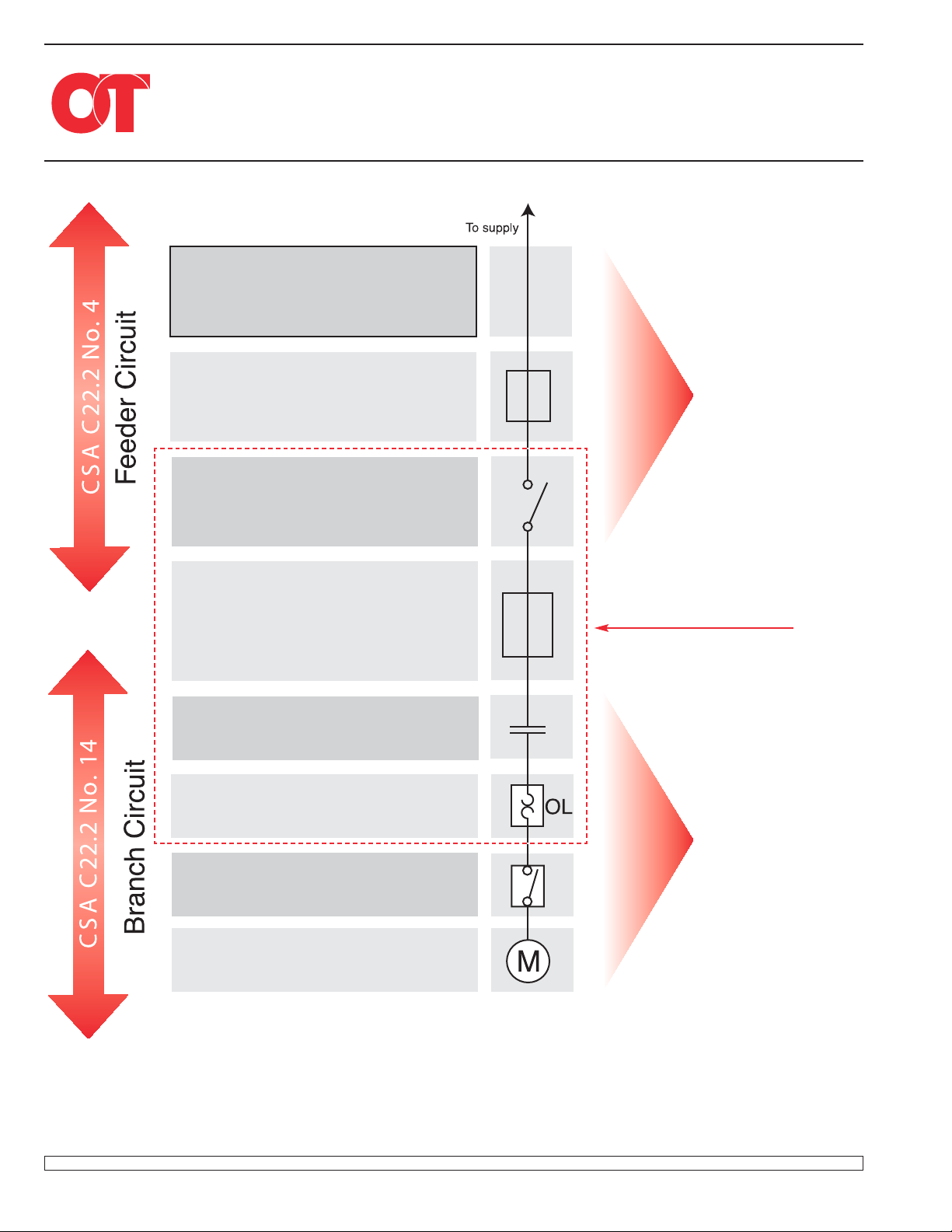
According to CEC
®
Section 28
Motor Feed
Motor feeder short circuit and ground
fault protection
Motor disconnecting means
(CEC ® 28-600, 28-604 (1)
600 (1), 28-602 (1)
Motor branch-circuit
short-circuit
protection
(CEC ® 28-200…28-210)
Motor controller
(CEC ® 28-500…28-504)
CSA C22.2 No. 4
Non-fusible Switches
OT30, OT60, OT100,
OT160, OT200, OT400,
OT600, OT800, OT1200,
OETL-NF1600...NF2000
CSA C22.2 No. 4
Fusible Switches
OS30, OS60, OS100,
OS200, OS400,
OS600, OS800, OS1200
Typical control panel
Motor overload protection
(CEC ® 28-302…28-308
OSHA Lockout/tagout disconnect
(CEC ® 28-600(3), 28-602(2), 28-604(2)
CSA C22.2 No. 14
Non-fusible Switches
OT16, OT25, OT40,
OT63, OT80
(CSA C22.2 No.4 switches
can also be applied)
Motor
General information : 1.1 – 1.7 Complete Non-fusible switches: 1.8 – 1.9 Components: 1.10 – 1.23 Technical information: 1.24– 1.29 Dimensions: 1.30 – 1.42
Discount schedule DS-H
1.32
Page 3
Auxiliary contact timing diagrams
OT16 – OT160
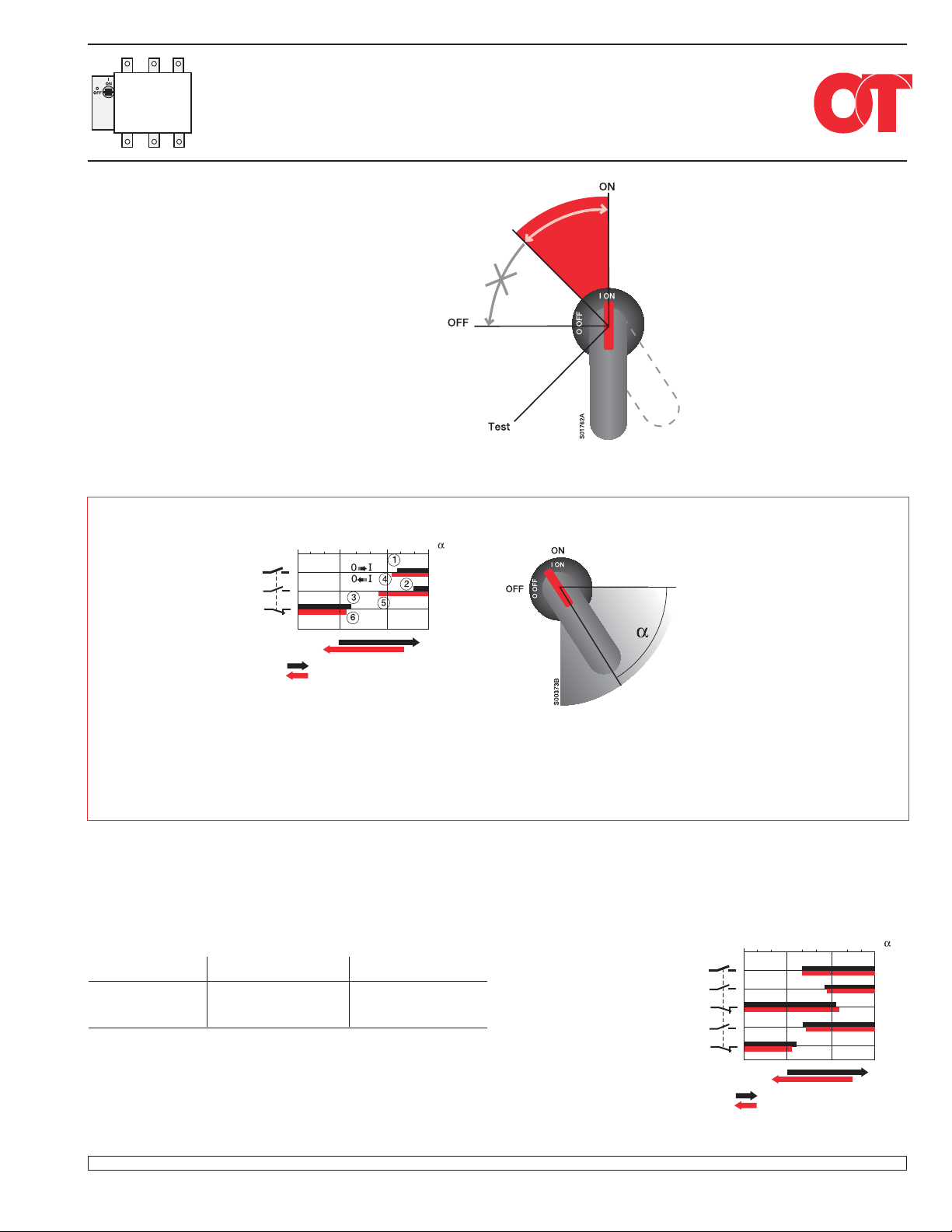
Handle indications and functions
• The handle indicates the position of the
contacts with complete reliability in all
situations.
If the contacts are welded together, the
handle doesn t reach the OFF-position
but remains between ON and OFF, maintaining
the door interlock and padlocking is not possible to do.
• When operating the switch to the
Test-position with a test handle the test
auxiliary contacts change position.
The main contacts remain open.
ON and OFF-functions of main and auxiliary contacts
0° 30° 60° 90°
Main contacts
N.O. auxiliary contact
N.C. auxiliary contact
OFF
0
= Contacts in closed position
= Contacts in closed position
Contacts closing Contacts opening
1 Main contacts close 4 Main contacts open
2 N.O. auxiliary contacts close 5 N.O. auxiliary contacts open
3 N.C. auxiliary contacts open 6 N.C. auxiliary contacts close
ON
I
OT16, OT25, OT40
Catalog number Auxiliary contact Contact configuration
OA1G10 1 N.O.
OT16, OT25, OT40 OA1G01 1 N.C.
OA2G11 1 N.O. & 1 N.C.
Early break
OA1G10
OA1G01
OA2G11
Main contacts
N.O. auxiliary contact
N.C. auxiliary contact
N.O. auxiliary contact
N.C. auxiliary contact
0° 30° 60° 90°
OFF
0
= Contacts in closed position
= Contacts in closed position
ON
I
General information : 1.1 – 1.7 Complete Non-fusible switches: 1.8 – 1.9 Components: 1.10 – 1.23 Technical information: 1.24– 1.29 Dimensions: 1.30 – 1.42
Discount schedule DS-H
1.33
Page 4
Auxiliary contact timing diagrams
for Non-fusible disconnect switches
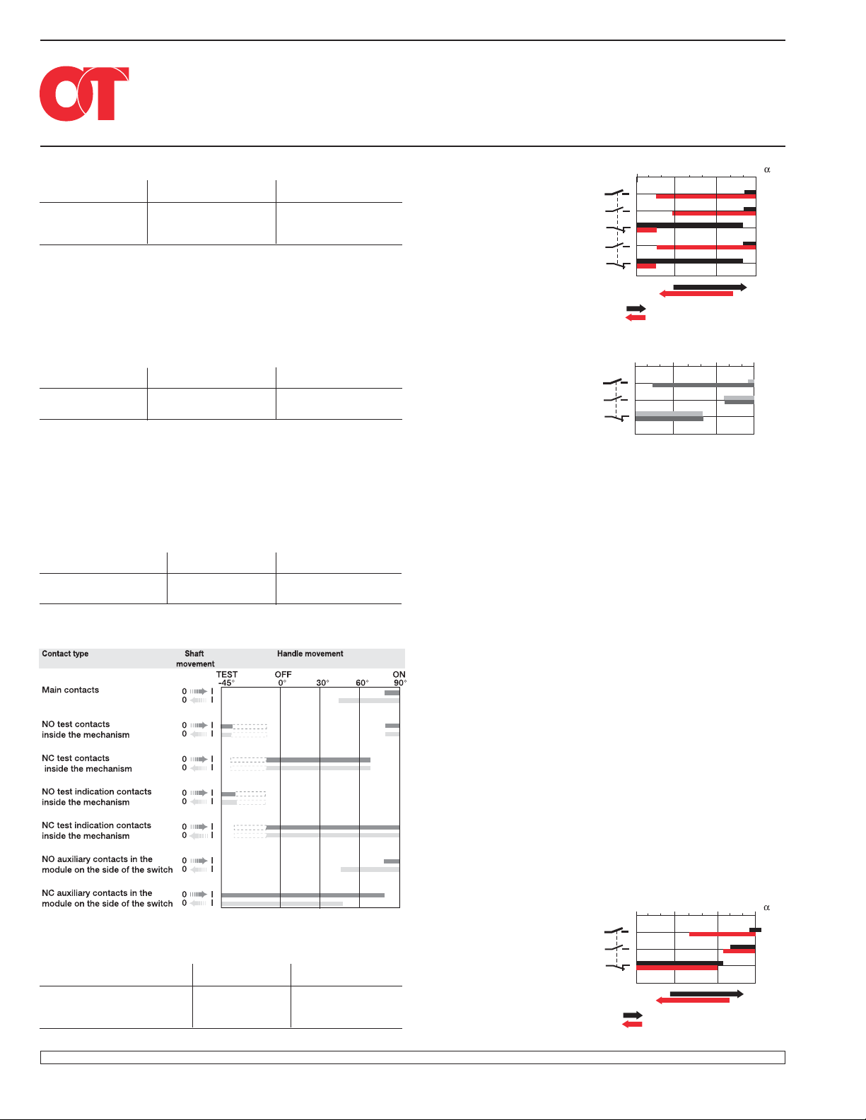
OT200 - OETL-NF2000
OT63, OT80, OT30, OT60, OT100
Catalog number Auxiliary contact Contact configuration
OA1G10 1 N.O.
OT63,OT80
OT30, OT60, OT100
OA1G01 1 N.C.
OA2G11 1 N.O. & 1 N.C.
OT160
Catalog number Auxiliary contact Contact configuration
OBEA10 1 N.O.
OT160
OBEA01 1 N.C.
OT200U03 – OT1200U03
Catalog number Auxiliary contact Contact configuration
OT200U03 – OT1200U03 OA1G10 1 N.O.
OA3G01 1 N.C.
Early break
OA1G10
OA1G01
OA2G11
Main contacts
N.O. auxiliary contact
N.C. auxiliary contact
N.O. auxiliary contact
N.C. auxiliary contact
Main contacts
N.O. auxiliary contact
N.C. auxiliary contact
0° 30° 60° 90°
OFF
0
= Contacts in closed position
= Contacts in closed position
o
OBEA10
OBEA01
o
60
90 α
ON
I
o
0
OFF
0
30
ON
I
o
S00081A
0° 30° 60° 90°
Main contacts
OETL-NF1600 – OETL-NF2000
Catalog number Auxiliary contact Contact configuration
OETL-NF1600 – OETL-NF2000 OZXK-1 1 N.O. & 1 N.C.
OZXK-2 2 N.O. & 2 N.C.
OZXK-3 4 N.O. & 4 N.C.
General information : 1.1 – 1.7 Complete Non-fusible switches: 1.8 – 1.9 Components: 1.10 – 1.23 Technical information: 1.24– 1.29 Dimensions: 1.30 – 1.42
Discount schedule DS-H
1.34
N.O. auxiliary contact
N.C. auxiliary contact
OZXK-1
OZXK-2
OZXK-3
OFF
0
= Contacts in closed position
= Contacts in closed position
ON
I
 Loading...