

Installation and
Maintenance manual
Softstarters
PST / PSTB

Installation and maintenance manual
PST30...PSTB1050
PST30... PST1050
Installation and maintenance manual
Introduction ....................................................................1.1 - 1.3
Quickstart ...............................................................2.1 - 2.3
Description ...................................................................3.1 - 3.10
Mounting ........................................................................4.1 - 4.3
Connection .....................................................................5.1 - 5.9
Human Machine Interface (HMI) ....................................6.1 - 6.7
Settings and confi guration ...........................................7.1 - 7.23
1
2
3
4
5
6
7
Fieldbus communication (option) ...................................8.1 - 8.2
Maintenance ...................................................................9.1 - 9.2
Functions ..................................................................10.1 - 10.19
Troubleshooting ..........................................................11.1 - 11.6
Diagrams ....................................................................12.1 - 12.5
Low Voltage Products & Systems I
ABB Inc. • 888-385-1221 • www.abb-control.com 1SXU 132 021 M0201
8
9
10
11
12
General information about this manual
1 General
This is the Installation and maintenance manual for Softstarters PST30...
PSTB1050
Document number: 1SXU 132 021 M0201
Edition: 01
Revision: 01
Issue Date: April 11, 2005
1
Date subject to change without notice.
We reserve all rights to this document, even in the event that a patent is
issued and a different commercial proprietary right is registered. Improper
use, in particular reproduction and dissemination to third parties, is not
permitted.
This document has been carefully checked. If the user nevertheless
detects any errors, please notify us as soon as possible.
The data contained in this manual is intended solely for the product description and is not to be deemed to be a statement of guaranteed properties. In the interests of our customers, we constantly seek to ensure that
our products are developed to the latest technological standards.
As a result, it is possible that there may be some differences between the
softstarter and the information in this manual.
Author’s address:
Low Voltage Products and Systems
ABB Inc.
1206 Hatton Road
Wichita Falls, TX 76302
Tel: 888.385.1221
940.397.7000
Fax: 940.397.7085
Web: www.abb-control.com
3 Safety signs
3:1 Use of Caution, Warning and Information
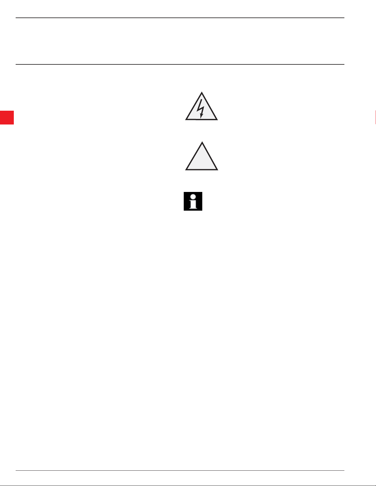
Caution icon indicates the presence of a hazard which could result
in personal injury.
!
Warning icon indicates the presence of a hazard which could result
in corruption of software or damage to equipment/property.
Alerts the reader to pertinent facts and conditions.
Caution!
Warning!
Information!
2 Safety
This section describes warning and information signs used in this manual.
The user should pay close attention to these signs.
The softstarter should be installed by authorized personnel only.
This manual is a part of the softstarter and should always be accessible to
personnel working with this product.
The manual should always be read before performing any installation or
commissioning tasks.
II Low Voltage Products & Systems
1SXU 132 021 M0201 ABB Inc. • 888-385-1221 • www.abb-control.com

Installation and maintenance manual
PST30...PSTB1050
About the documentation for the softstarter .........................................................1.2
About the installation and commissioning manual ...............................................1.2
Intended audience ........................................................................................ 1.2
General ...................................................................................................... 1.2
Requirements ............................................................................................. 1.2
Chapters included ................................................................................................. 1.2
Revision notes .......................................................................................................1.3
Acronyms and abbreviations ................................................................................. 1.3
Chapter 1
Introduction
1
Low Voltage Products & Systems 1.1
ABB Inc. • 888-385-1221 • www.abb-control.com 1SXU 132 021 M0201

Chapter 1
Introduction
1:1 About the documentation for the softstarter
For the softstarter, the following documents are available:
PST30/PSTB1050 Softstarters
Installation and Maintenance manual
Document ID: 1SXU 132 021 M0201 - English
1SFC132003M0101 (German)
1SFC132003M0101 (German)
1
1SFC132003M3401 (Swedish)
1SFC132003M0301 (French)
1SFC132003M0901 (Italian)
1SFC132003M0701 (Spanish)
1SFC132003M3101 (Dutch)
1SFC132003M1601 (Portuguese)
1SFC132003M1801 (Finnish)
1SFC132003M1101 (Russian)
1SFC132003M2001 (Chinese
1SFC132003M1901 (Turkish)
Soft Starter Catalog
Document ID: 1SXU 132 019 C0201
For other documents related to the PST Softstarters, see www.abb-control.com/products/softstarters.htm#type_pst
1:2 About the installation and commissioning manual
This manual contains instructions on how to install and commission the softstarter. The manual covers procedures for mechanical and electrical installation and installation of communication devices. It also covers how to energize, set, confi gure and verify settings.
For the quickest possible start, read Chapter 2 “ Quickstart” .
1:2.1 Intended audience
1:2.1.1 General
The installation and commissioning manual is intended for personnel responsible for installing, commissioning and maintaining the softstarter.
1:2.1.2 Requirements
All personnel who interact with the softstarter must have a basic knowledge in handling electric equipment. The commissioning and maintenance personnel must be well experienced in using this kind of equipment.
1:2.2 Chapters included
• Introduction introduces the reader to this manual.
• Quickstart contains information on how to install the softstarter and put it into oper ation in the quickest and safest way. This chapter is intended for
the experienced user.
• Description describes the softstarter in general, its functions and specifi cations.
• Mounting contains information on receiving, unpack ing and mounting the softstarter.
• Connection contains instructions on how to make the electrical connections as well as connections for com munication devices.
• Human-Machine Interface describes the local Human-Machine Interface, how it works and what it contains.
• Settings and confi guration describes all possible set tings and how to navigate in the menu system.
• Fieldbus communication describes how to install and set up the fi eldbus communication.
• Maintenance describes what maintenance is required.
• Functions describes all functions included in the soft starter. This chapter also describes parameter ranges and default values.
• Trouble shooting contains instructions on how to quickly fi nd and correct the most common faults.
• Diagrams contains a number of electrical diagrams for the softstarter itself. It also contains some typical application diagrams.
1.2 Low Voltage Products & Systems
1SXU 132 021 M0201 ABB Inc. • 888-385-1221 • www.abb-control.com

Chapter 1
Introduction
1:2.3 Revision notes
Please check www.abb-control.com/products/softstarters.htm#type_pst for latest information on revisions.
1.2.4 Acronyms and abbreviations
The following acronyms and abbreviations are used in this manual.
Acronym/abbreviation Description
LED Light Emitting Diode
LCD Liquid Crystal Display
SCR Silicon Controlled Rectifi er
IT Information T echnology
HMI Human-Machine Interface
FBP Fieldbusplug
PLC Programmable Logic Controller
PCB Printed Circuit Board
TOR Top of Ramp (full voltage)
1
Low Voltage Products & Systems 1.3
ABB Inc. • 888-385-1221 • www.abb-control.com 1SXU 132 021 M0201

Notes
1
1.4 Low Voltage Products & Systems
1SXU 132 021 M0201 ABB Inc. • 888-385-1221 • www.abb-control.com

Installation and maintenance manual
PST30...PSTB1050
Connection .............................................................................................................2.2
Confi guration ..........................................................................................................2.3
Start of the motor ....................................................................................................2.3
Chapter 2
Quickstart
2
Low Voltage Products & Systems 2.1
ABB Inc. • 888-385-1221 • www.abb-control.com 1SXU 132 021 M0201
Chapter 2
Quickstart
1
Power on ProtectionFault
2
4
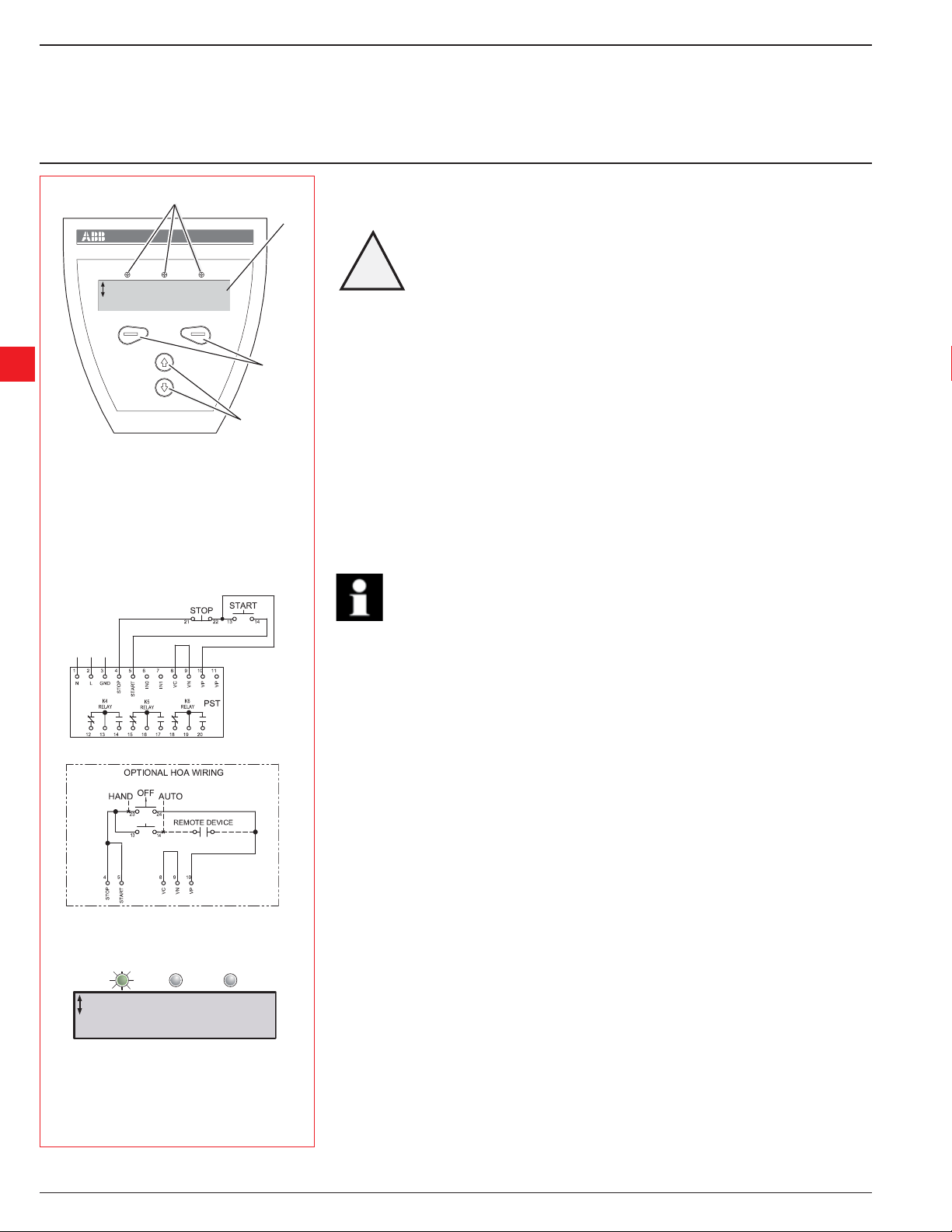
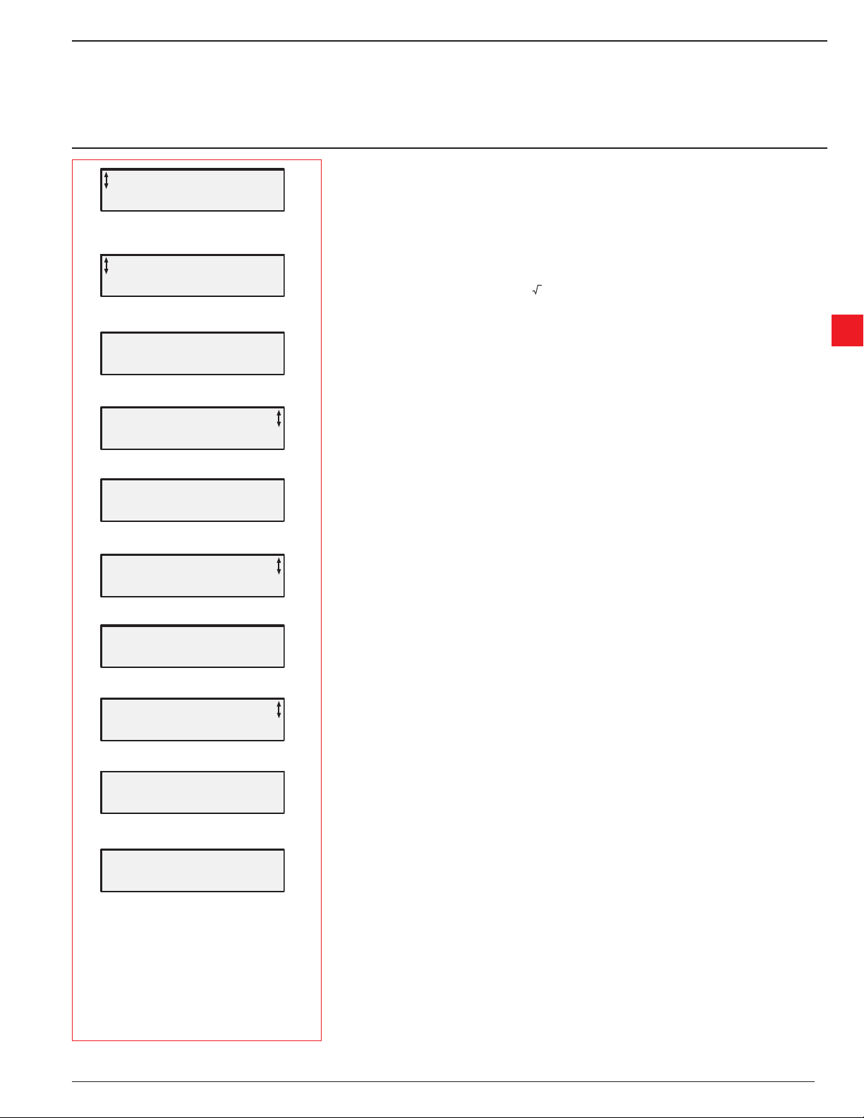
Figure 1:
1 Status indication LEDs
2 LCD display
3 Selection keys for selecting, changing and storing parameters
4 Navigation keys for navigating in the menus
* Arrows shown in the display indicate that the value/menu is
possible to change or scroll
This chapter is a short guide on how to connect, confi gure and start the softstarter in the quickest
and safest way.
2
!
Warning!
Mounting and installing the softstarter shall be done in accordance with local laws and
regulations and must be performed by authorized personnel only.
Do not change any parameters in the Service Settings menu.
3
2:1 Connection
1. Mount the softstarter according to Chapter 4 “ Mounting” .
2. Be aware of the ambient temperature. Derating is required above 40 °C (104 °F). See Chapter
3 for more information.
3. Connect the main circuit: terminals 1L1 - 3L2 - 5L3 to the line side and terminals
2T1 - 4T2 - 6T3 to the motor side.
4. Connect the control voltage: terminals 1 and 2 (100-250V 50/60Hz).
5. Connect the functional ground: terminal 3.
Figure 2: Standard connection PST
Power on ProtectionFault
Figure 3: Top level
Information!
The wire shall be as short as possible, and be connected to the mounting plate.The
mounting plate should also be grounded.
6. Connect the start/stop circuits: terminal 4, 5, 8, 9 and 10 according to Figure 2. 24 VDC only!
7. Verify that the main and control voltage corresponds to the softstarter ratings.
8. Switch on the control voltage.
9. The green “Power on” LED should be lit and the LCD should appear as shown in Figure 3.
2.2 Low Voltage Products & Systems
1SXU 132 021 M0201 ABB Inc. • 888-385-1221 • www.abb-control.com
Chapter 2
Quickstart
Application Setting
Select Back
Figure 4: Application setting menu
Centrifugal Pump
Store Set Back
Figure 5: Centrifugal pump
Centrifugal Pump
Next Back
Figure 6: Centrifugal pump stored
Setting Ie 99.0A
Store
Figure 7: Setting Ie
Setting Ie 99.0A
Next Back
Figure 8: Setting Ie stored
OL Class 10
Store
Figure 9: OL Class
2:2 Confi guration
1. Enter the Application Setting by pressing the left selection key twice. Press Select using the
left selection key. See Figure 4.
2. Select the appropriate type of load by using the navigation keys. See Figure 5.
3. Press Store Set and Next to continue or Back to previ ous parameter using the selection
keys. See Figure 6.
4. Set Ie (motor FLA) using the navigation keys.
In Line connected = rated motor current
Inside Delta connected = 58% (1/( 3)) of the rated motor current. For example, if the soft
starter is connected in line with a 100A motor, Ie = 100A. If the softstarter is connected inside
the delta of a 100A motor, Ie = 58A. See Figure 7.
5. Press Store and Next to continue or press Back to access the previous parameter. See Fig-
ure 8.
6. Set the required overload class using the navigation keys. See Figure 9.
7. Press Store and Next to continue or press Back to access the previous parameter. See Fig-
ure 10.
8. If an external by-pass contactor is used set Ext ByPass to Yes using the navigation keys.
(PST30...300 only). See Figure 11.
9. Press Store and Next to continue or Back to previous parameter using the selection keys.
See Figure 12.
10. Select Yes if ready or Tune Set if ramp times, initial voltage, current limit etc. need to be
adjusted. See Figure 13.
11. To change language, see Section 7:2.5.
2:3 Start of the motor
1. Switch on the main voltage.
2. Give a start command to the softstarter.
(To start the softstarter from the keypad, enter the LOCAL CONTROL menu, select Start/
Stop and press Start. The motor must be stopped before leaving this menu.)
2
OL Class 10
Next Back
Figure 10: OL Class stored
Ext ByPass No
Store
Figure 11: External Bypass
Ext ByPass No
Next Back
Figure 12: External Bypass stored
Ready?
Yes Tune Set
Figure 13: Ready / Tune Set
Low Voltage Products & Systems 2.3
ABB Inc. • 888-385-1221 • www.abb-control.com 1SXU 132 021 M0201

Notes
2
2.4 Low Voltage Products & Systems
1SXU 132 021 M0201 ABB Inc. • 888-385-1221 • www.abb-control.com

Installation and maintenance manual
PST30...PSTB1050
Overview.................................................................................................................3.2
Functions ................................................................................................................3.2
Markings and connections ......................................................................................3.3
Type designation ....................................................................................................3.4
Industrial IT .............................................................................................................3.4
Environmental infl uence .........................................................................................3.4
Specifi cations .........................................................................................................3.4
Technical data ........................................................................................................3.5
General .............................................................................................................3.5
Semi-conductor fuses .......................................................................................3.5
Softstarter types ................................................................................................3.6
Weights .............................................................................................................3.7
PSTB AC3 (Across the line) Contactor Ratings ................................................3.7
UL Information ...................................................................................................3.7
Dimensions ............................................................................................3.8 - 3.10
Chapter 3
Description
3
Low Voltage Products & Systems 3.1
ABB Inc. • 888-385-1221 • www.abb-control.com 1SXU 132 021 M0201
Chapter 3 - Description
This chapter describes the softstarter in general, specifi cations and available accessories and
spare parts.
3:1 Overview
The PST softstarter is a microprocessor-based softstarter designed with the latest technology for
the soft start and soft stop of squirrel cage motors. The softstarter has several advanced motor
protection features as standard.
The softstarter is designed to be used with or without a by-pass contactor except for the larger
sizes, PSTB370...1050 where the bypass contactor is integrated. In an emergency, it is possible
to start the motor across the line with the integrated bypass contactor. See Section 3:8.4 for AC3
ratings.
The keypad on the front is designed to be as user-friendly as possible, with a clear text display. It
is possible to choose between twelve different languages (default is English).
The softstarter can be controlled in four ways:
3
• Hardware inputs
• Keypad control (local)
• Fieldbus communication interface
• Remote keypad (option)
The integrated fans for cooling are operated only during ramping (start/stop) and when the tem-
perature of the heat sink is too high. The temperature is monitored by a thermistor.
Only one type of control method can be enabled simultaneously.
Default selection is hardware inputs.
Information!
Keypad control has the highest priority and overrides all other control methods.
3:2 Functions
The PST softstarter has several integrated protection and warning functions. Almost any type of
fault can be detected and displayed.
All available protections, warnings and fault indications are listed below.
Start/Stop functions
• Start ramp
• Stop ramp (also called soft stop or decel)
• Initial voltage
• Step down voltage
• Current limit
• Kick Start
• Extended start range
• Extended stop range
• Sequence start
Protection functions
• Motor overload protection
• Locked rotor protection
• Motor underload protection
• High current protection
• Phase imbalance protection
• Phase reversal protection
• SCR overload protection
• PTC input for motor protection
• Shorted SCR
3.2 Low Voltage Products & Systems
1SXU 132 021 M0201 ABB Inc. • 888-385-1221 • www.abb-control.com
Chapter 3 - Description
Warning functions
• Warning high current
• Warning low current
• Warning motor overload
• Warning SCR overload
Fault Supervision functions
• Internal softstarter faults
• Shorted SCR
• Non conducting SCR
• Open circuit motor side
• Over-temperature heat sink
• Phase loss
• Frequency out of range
• Fieldbus communication
• Non-closing by-pass contactor
• Non-opening by-pass contactor
Other functions
• Jog
• Real time clock
• Event log
• Keypad password
3
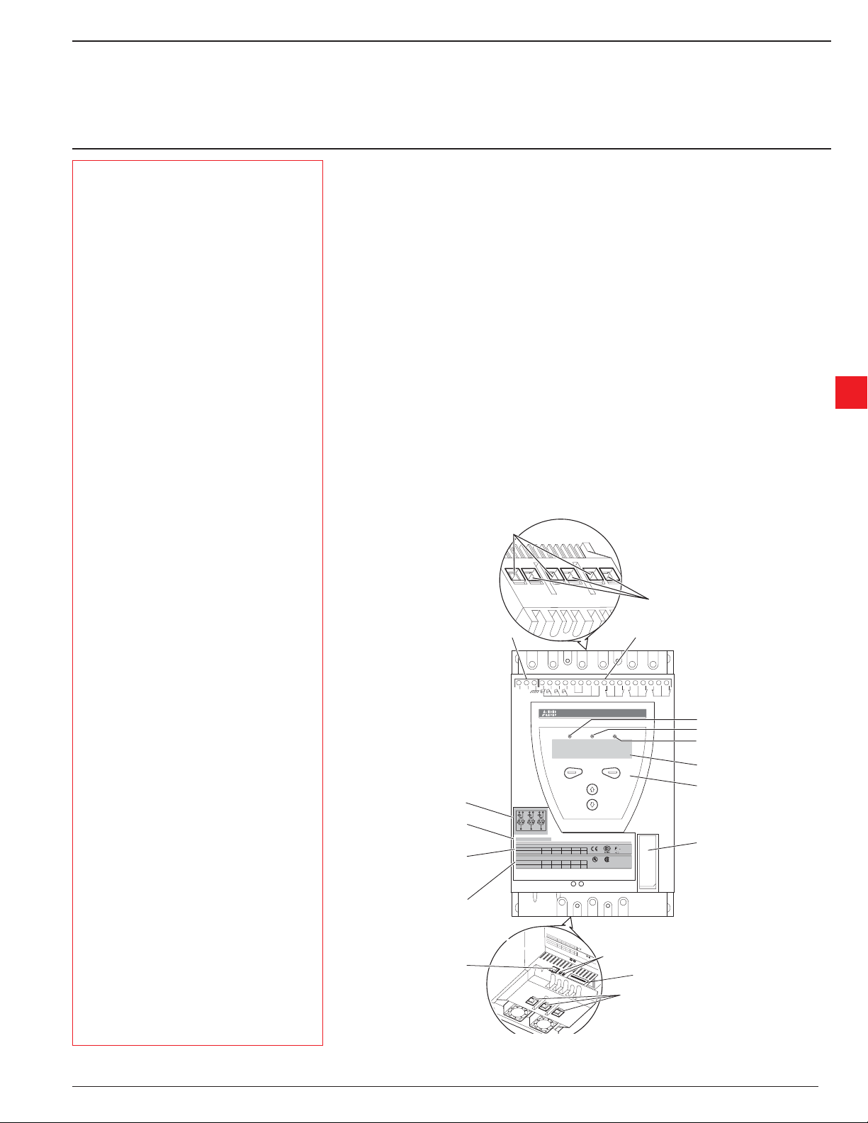
3:3 Markings and connections
Line side
connection
e
1234567891011121314151617181920
L
N
100-250V
Stop
50/60 Hz
1L1
B1 B2 B3
3L2 5L3
2T1 4T2 6T3
1SFA 894 007 R1002
IEC 947-4-2
Us: 100-250V AC/DC
Ie: 37-72A
Overload Capacity 115% of Continuous
UL 508
Uc: 100-250V AC/DC
FLA: 37-68A
Fuse 250A TYPOWER ZILOX
CAUTION
Max short circuit current 65kA at 480V
Terminal marking
of main circuit
Order code
Technical data
according to
IEC 947-4-2
Technical data
according to
UL 508
Control voltage U
Start
In1 Vc Vn Vp Vp
In0
Made in Sweden
72: AC-53a: 8-1.6: 80-6
Ue: 220-230 380-400 500 V
In line 18,5 37 45 kW
Ue 208 220-240 440-480 V
In line 20 20 50 Hp
PTCKeypad Fieldbus
IND. CONT. EQ
LISTED
7F39
K4
Wire 1-8 Al Cu 75C only, 35lb-in
Bypass connection
(PST30...300 only)
Terminal marking
of control circuits
K5 K6
Green
Red
Yellow
Display
Keypad
Fieldbus connection
Us: 100
-250V AC/DC
Ie: 37-7
2A
UL
Ue:
Uc: 100
In line
220-23
-250V AC/DC
Overload Capacity
FLA: 37-6
0
18,5
380-400
8A
CAUTI
Ue
37
1
15% of Contin
500
ON
Fuse 250
In lin
V
45
Max short circui
208
e
uous
A
T
kW
YPOW
22
20
0-240
ER ZILOX
t current 65kA
44
20
0-480
L
IS
50
V
at
T
ED
Keypad
IND. C
7
F3
Hp
ON
9
T
.
EQ
.
PTC connection
External keypad
connection
PTC
Wire 1-8
Al Cu 75C
only, 35lb-in
Fieldb
us
213
11
456789101
123
103020123
1S160100
Serial number
Motor side connection
Figure 1: Markings and connections
Low Voltage Products & Systems 3.3
ABB Inc. • 888-385-1221 • www.abb-control.com 1SXU 132 021 M0201
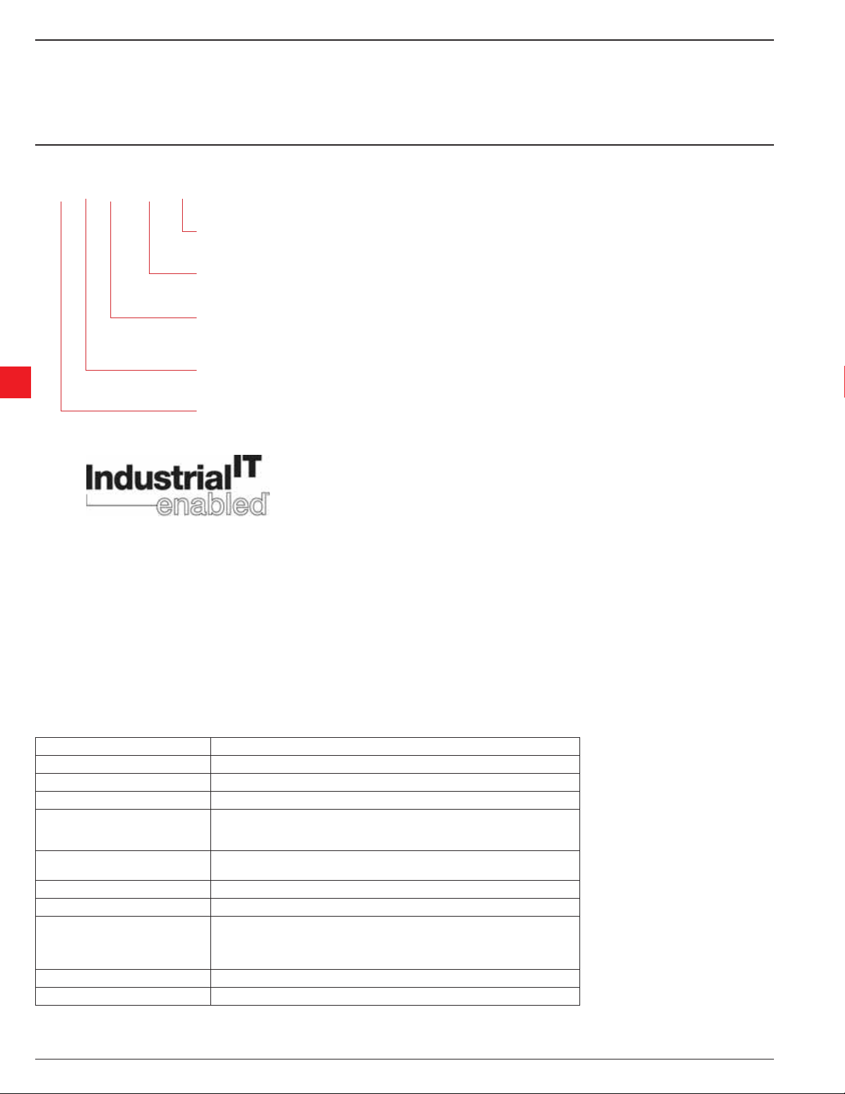
3:4 Type designation
Chapter 3 - Description
]
PST B 370-600 -70
]
3
3:4 Industrial
]
]
]
Control Voltage
70 = 100 - 250V 50/60 Hz
Main Voltage
600 = 208 - 600V 50/60 Hz
690 = 400 - 690V 50/60 Hz
Current Rating
600 = 208 - 600V 50/60 Hz
690 = 400 - 690V 50/60 Hz
Bypass contactor
600 = 208 - 600V 50/60 Hz
690 = 400 - 690V 50/60 Hz
Softstarter type
IT
Thanks to ABB’s broad program of product standardisation, today’s Industrial IT components are - whether they are products or systems, hardware or
software - the building blocks of larger solutions, incorporating functionalities that will allow seamless interactions in real-time automation and information systems.
At the product level, ABB’s Industrial IT enabled symbol ensures that all the products can fully interact. All product information pertaining to these
products is available in electronic format, based on Aspect Object
equipped with the tools necessary to install, operate and maintain it effi ciently throughout the product’s life cycle.
The PST softstarters is an Industrial IT enabled product. Documentation such as brochures, catalogues, certifi cates and drawings can be found at :
www.abb-control.com/products/softstarters.htm#type_pst.
TM
technology. The Industrial IT commitment from ABB ensures that every product is
3:6 Environmental infl uence
The product is designed to minimize the environmental affects during manufacturing and use of the product. Most of the materials used are recyclable.
3:7 Specifi cations
Item Specifi cation
Degree of protection (main circuit) IP 10 for PST30...72; IP 00 for PST85...1050
Operating position Vertical at ± 10°
Ambient temperature Storage: -25°C to +70°C (-13°C to 158°F)
Operation
Without derating
With derating
Altitude 1000 m (3281 ft.) above sea level without derating
Pollution degree 3
Relative humidity 5 - 95% (non-condensing)
Standards UL508
PTC input IEC 60947-8 Mark A detectors, DIN 44081 and DIN 44082
Marine approvals Contact your ABB sales offi ce
3.4 Low Voltage Products & Systems
1SXU 132 021 M0201 ABB Inc. • 888-385-1221 • www.abb-control.com
0°C to +40°C (32°F to 104°F)
+40° C to +50°C (104°F to 122°F) of 0.8% / °C (1.8%/°F)
1000 - 4000 m (3281 - 13,123 ft.) by derating 1% for each 333 ft above 3300 ft.
IEC 60947-1
IEC 60947-4-2
EN 60947--1
Chapter 3 - Description
3:8 Technical data
3:8.1 General
Item Technical data
Rated insulation voltage, Ui 690V
Rated operational voltage, Ue 208-690 V (in two modes)
Rated control voltage, Us 100 - 250 V 50/60 Hz
Rated frequency 50 / 60 Hz
Voltage tolerances +10% to -15%
Frequency tolerances ±5%
Rated impulse withstand voltage 2 kV
Number of controlled phases 3
Programmable inputs 24 VDC, 10 mA
Output relays 250 VAC, Ith = 5A, le = 1.5A (AC-15)
Battery back-up D20mm Lithium 3V CR2032
PTC input 2825 ohm ±20% switch off resistance
1200 ohm ±20% switch on resistance
Cooling system Fan
Recommended fuse for control circuit 6A Delayed
MCB use C characteristics
Service factor 115% (100% for PSTB1050)
Communication protocols AS-Interface DeviceNet / Profi bus DP /
Modbus
3
3:8.2 Semi-conductor fuses
Softstarter type Bussmann fuses Holders
A Type
PST30 80 170M1366 170H1007
PST37 125 170M1368 170H1007
PST44 160 170M1369 170H1007
PST50 160 170M1369 170H1007
PST60 200 170M1370 170H1007
PST72 250 170M1371 170H1007
PST85 315 170M1372 170H1007
PST105 400 170M3019 170H3004
PST142 450 170M3020 170H3004
PST175 500 170M3021 170H3004
PST210 630 170M5012 170H3004
PST250 700 170M5013 170H3004
PST300 900 170M5015 170H3004
PSTB370 700 170M5013 170H3004
Low Voltage Products & Systems 3.5
ABB Inc. • 888-385-1221 • www.abb-control.com 1SXU 132 021 M0201

Chapter 3 - Description
3:8.3 Softstarter types
Type PST30 PST37 PST44 PST50
Connection method Inline Delta Inline Delta Inline Delta Inline Delta
Rated Current Ie (A) 30 52 37 64 44 76 50 85
Motor rating at 480V (HP) 20 30 25 40 30 50 40 60
Motor rating 380-415V (KW) 15 25 18.5 30 22 37 25 45
AC-3 Rating with integrated Bypass (A) ––––
Power loss at rated current (W) 100 120 140 160
Control power requirements (VA) 5555
Type PST60 PST72 PST85 PST105
Connection method Inline Delta Inline Delta Inline Delta Inline Delta
Rated Current Ie (A) 60 105 72 124 85 147 105 181
3
Motor rating at 480V (HP) 40 75 50 75 60 100 75 150
Motor rating 380-415V (KW) 30 55 37 59 45 75 55 90
AC-3 Rating with integrated Bypass (A) ––––
Power loss at rated current (W) 190 230 270 325
Control power requirements (VA) 5 5 10 10
Type PST142 PST175 PST210 PST250
Connection method Inline Delta Inline Delta Inline Delta Inline Delta
Rated Current Ie (A) 142 245 175 300 210 360 250 430
Motor rating at 480V (HP) 100 150 125 200 150 250 200 350
Motor rating 380-415V (KW) 75 132 90 160 110 184 132 220
AC-3 Rating with integrated Bypass (A) ––––
Power loss at rated current (W) 435 540 645 765
Control power requirements (VA) 10 15 15 15
Type PST300 PSTB370 PSTB470 PSTB570
Connection method Inline Delta Inline Delta Inline Delta Inline Delta
Rated Current Ie (A) 300 515 370 640 470 814 570 987
Motor rating at 480V (HP) 250 400 300 500 400 600 500 700
Motor rating 380-415V (KW) 160 257 200 355 250 450 315 475
Contactor type – AF302 AF302 AF480
AC-3 Rating with integrated Bypass (A) – 302 302 480
Power loss at rated current (W) 920 90 110 110
Control power requirements (VA) 15 20/480 20/480 25/900
Type PSTB720 PSTB840 PSTB1050
Connection method Inline Delta Inline Delta Inline Delta
Rated Current Ie (A) 720 1247 840 1455 1050 1810
Motor rating at 480V (HP) 600 1000 700 1200 900 1500
Motor rating 380-415V (KW) 400 670 450 780 560 875
Contactor type AF580 AF750 AF750
AC-3 Rating with integrated Bypass (A) 590 720 720
Power loss at rated current (W) 110 170 170
Control power requirements (VA) 25/860 25/860 25/860
3.6 Low Voltage Products & Systems
1SXU 132 021 M0201 ABB Inc. • 888-385-1221 • www.abb-control.com

Chapter 3 - Description
3:8.4 Weights
Type Weight in kg Weight in lbs
PST30...50 4.8 10.6
PST60...72 5.0 11.0
PST85 11.2 24.7
PST105...142 13.0 28.7
PST175...210 21.5 47.4
PST250...300 23.0 50.7
PST370...470 31.0 68.3
PSTB570 52.0 114.6
PSTB720 55.0 121.3
PSTB840...1050 60.0 132.3
3:8.5 PSTB AC3 Integrated contactor ratings
PST type PSTB370 PSTB470 PSTB570 PSTB720 PSTB840 PSTB1050
Contactor type AF300 AF300 AF460 AF580 AF750 AF750
AC3 Rating @ 480V HP 250 250 400 500 600 600
AC3 Rating A 302 302 480 590 720 720
3
3:8.6 UL information
Equipment suitable for use in a circuit with maximum available fault current as shown when protected by devices indicated.
Model Rating (kA) Max V Fuse (A) MCCB (A)
PST30...142 10 600 Any UL Listed Any UL Listed
PST175...300 18 600 Any UL Listed Any UL Listed
PSTB370...470 30 600 Any UL Listed Any UL Listed
PSTB570 30 600 Any UL Listed Any UL Listed
PSTB720 42 600 1200/L 1200
PSTB840 42 600 1200/L 1200
PSTB1050 85 480 - 800
PSTB1050 85 600 1200/L PSTB1050 42 600 - 1200
Low Voltage Products & Systems 3.7
ABB Inc. • 888-385-1221 • www.abb-control.com 1SXU 132 021 M0201
Chapter 3 - Description
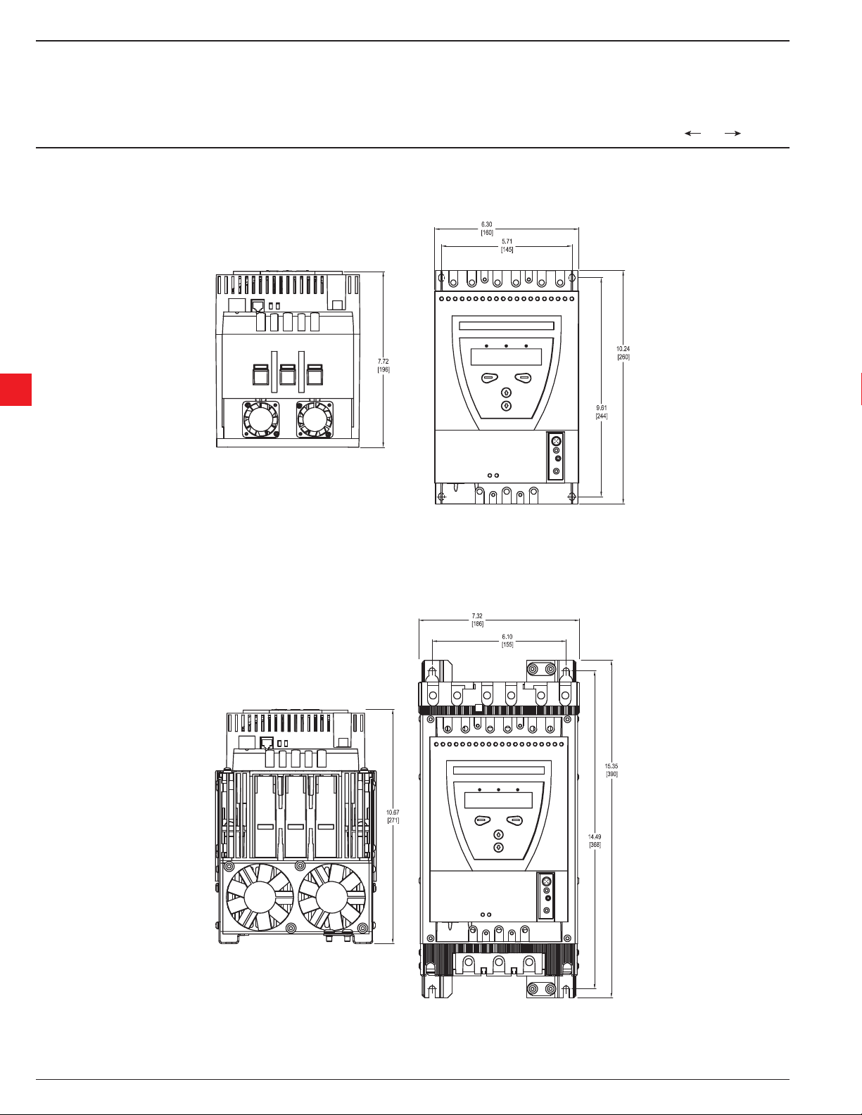
3:8.7 Dimensions
PST30...72
3
Figure 1: Dimensions PST30...72
[
Inches
[
Millimeters
PST85...142
Figure 2: Dimensions PST85...142
3.8 Low Voltage Products & Systems
1SXU 132 021 M0201 ABB Inc. • 888-385-1221 • www.abb-control.com
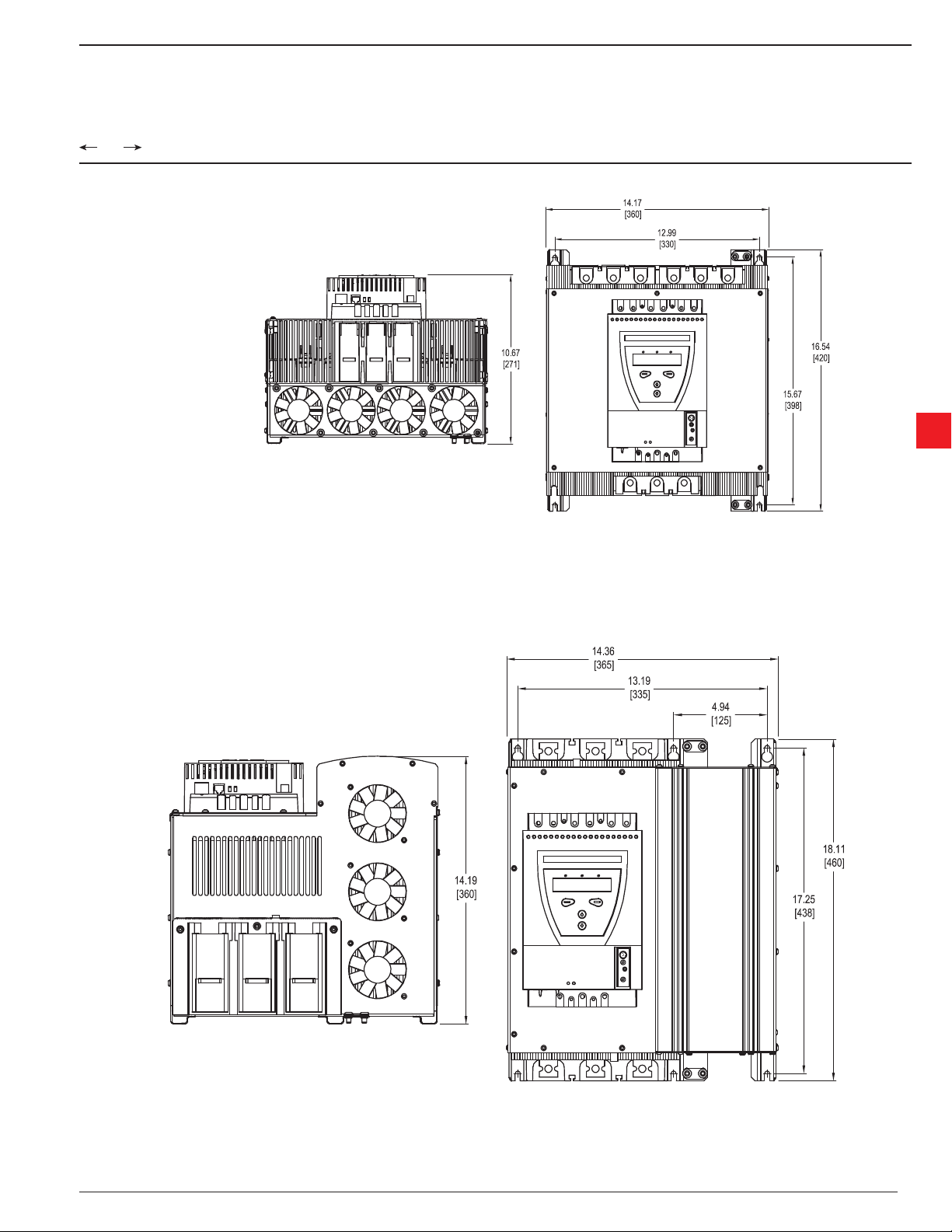
Chapter 3 - Description
[
Inches
[
Millimeters
PSTB175...300
3
Figure 3: Dimensions PST175...300
PSTB370...470
Figure 4: Dimensions PSTB370...470
Low Voltage Products & Systems 3.9
ABB Inc. • 888-385-1221 • www.abb-control.com 1SXU 132 021 M0201
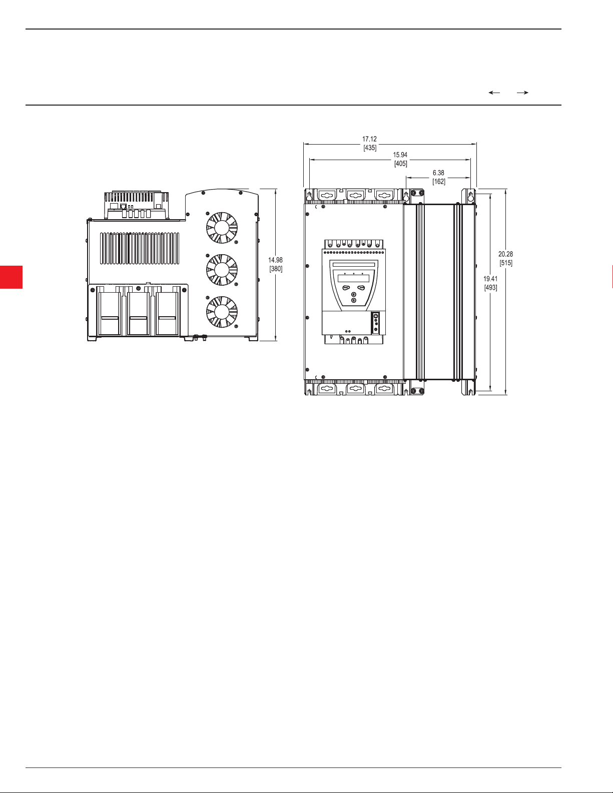
Chapter 3 - Description
PSTB570...1050
3
[
Inches
[
Millimeters
Figure 5: Dimensions PSTB570...1050
3.10 Low Voltage Products & Systems
1SXU 132 021 M0201 ABB Inc. • 888-385-1221 • www.abb-control.com

Installation and maintenance manual
PST30...PSTB1050
Receiving, unpacking and checking .......................................................................4.2
Intermediate storage .........................................................................................4.2
Mounting .................................................................................................................4.2
Handling when mounting ..................................................................................4.2
Requirements ....................................................................................................4.2
Minimum distance to wall/front ..........................................................................4.2
Minimum enclosure sizes ..................................................................................4.3
Chapter 4
Mounting
4
Low Voltage Products & Systems 4.1
ABB Inc. • 888-385-1221 • www.abb-control.com 1SXU 132 021 M0201
Chapter 4
Mounting
This chapter describes instructions on how to receive the softstarter and how to mount it in the proper
way.
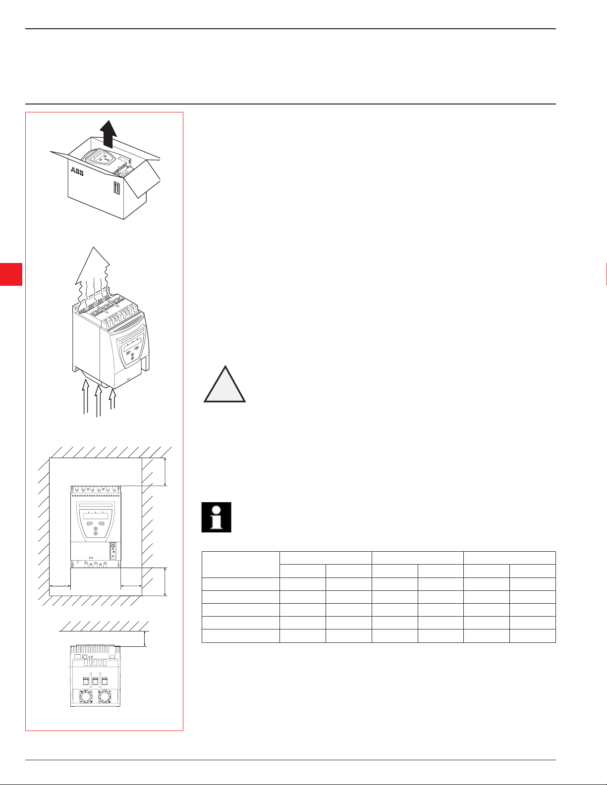
4:1 Receiving, unpacking and checking
• Check that the package is turned with the correct side up, Figure 1.
• Check for transport damages
• Remove transport casing.
• Visually inspect the softstarter
• Check that the serial number corresponds with the delivery documents
Figure 1: Package
4
• Check the softstarter as well as the package. If you fi nd any damages, please contact the transport
company or supplier immediately.
4:1.1 Intermediate storage
Until the softstarter is mounted, it should be stored in its package.
4:2 Mounting
4:2.1 Handling when mounting
The softstarter is available in fi ve physical sizes. Models PST30 to PST300 can be taken out of the
packages and mounted without lifting equipment.
For all other models, lifting equipment is recommended due to the weight.
See Chapter 3 “Description”, for weights.
Figure 2: Airways
B B
Do not lift the softstarter by the connection bars. Lifting by the connection bars may cause
4:2.2 Requirements
See Chapter 3 “Description” for environmental requirements.
A
4:2.3 Minimum distance to wall/front
To ensure a suitable cooling, the softstarter must be mounted vertically and in such a way that the
Use the table below and Figure 3 for minimum distances between wall/front of the PST softstarter.
The values are minimum distances.
A
C
!
Warning!
damage to the product.
airways are not blocked, see Figure 2.
Information!
Softstarter type
PST30...72 100 3.94 10 0.39 20 0.79
PST85...300 100 3.94 10 0.39 20 0.79
PST175...300 100 3.94 10 0.39 20 0.79
PSTB370...470 150 5.91 15 0.59 20 0.79
PSTB570...1050 150 5.91 15 0.59 20 0.79
ABC
mm in mm in mm in
Figure 3: Minimum distances, wall/front
4.2 Low Voltage Products & Systems
1SXU 132 021 M0201 ABB Inc. • 888-385-1221 • www.abb-control.com

Chapter 4 - Mounting
4:2.4 Minimum enclosure sizes
In applications where the softstarter is installed in an enclosure, the following minimum
enclosure sizes and fan capacities are recommended.
Minimum enclosure dimensions
Softstarter type
PST30...72 300 12 400 16 250 10 42 25
PST85...300 400 16 500 20 300 12 95 60
PST175...300 500 20 600 24 300 12 210 125
PSTB370...470 600 24 600 24 400 16 210 125
PSTB570...1050 750 30 900 36 400 16 210 125.00
WHD
mm in mm in mm in m3/h ft3/min
Fan capacity
Dimensions and drilling plan: See Chapter 3, “Description”
4
Low Voltage Products & Systems 4.3
ABB Inc. • 888-385-1221 • www.abb-control.com 1SXU 132 021 M0201

Notes
4
4.4 Low Voltage Products & Systems
1SXU 132 021 M0201 ABB Inc. • 888-385-1221 • www.abb-control.com

Installation and maintenance manual
PST30...PSTB1050
General .................................................................................................................5.2
Electrical connection .............................................................................................5.2
Main circuit .......................................................................................................5.2
External Bypass contactor ...............................................................................5.3
Protective earthing ...........................................................................................5.3
Control voltage and control circuit ....................................................................5.4
Control voltage, terminals 1 and 2 ...........................................................5.4
Grounding, terminal 3 ..............................................................................5.4
Start and Stop, terminals 4, 5, 8, 9, 10, 11 ...............................................5.4
Programmable inputs, terminals 6 and 7 .................................................5.5
Programmable output relay K4, terminals 12, 13 and 14 ........................5.6
Programmable output relay K5, terminals 15, 16 and 17 ........................5.7
Programmable output relay K6 terminals 18, 19 and 20 .........................5.7
PTC input .................................................................................................5.7
Connection of communication devices (optional) ..................................................5.8
Fieldbus communication ..................................................................................5.8
External keypad ...............................................................................................5.8
Transferring parameters ...................................................................................5.8
Uploading parameters .............................................................................5.8
Technical data ..........................................................................................5.9
Chapter 5
Connection
5
Low Voltage Products & Systems 5.1
ABB Inc. • 888-385-1221 • www.abb-control.com 1SXU 132 021 M0201
Chapter 5
Connection
This chapter describes the electrical connections as well as connections for communication
devices (optional) that must be made before the softstarter can be operated.
5:1 General
PST30...
PSTB1050
Caution!
All wiring and connection must be carried out by a qualifi ed electrician, and in
accordance with installation standards and safety regulations.
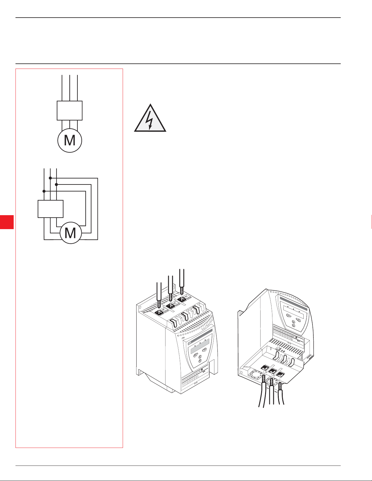
Figure 1: In Line Connection
PST30...
PSTB1050
5
Figure 2: Inside Delta connection
See Chapter 2 “ Quickstart”.
5:2 Electrical connection
5:2.1 Main circuit
Softstarters PST30...PSTB1050 can be connected both “ In Line”, see Figure 1, and “ In-
side Delta”, see Figure 2.
Connect the line side to terminals 1L1, 3L2, 5L3.
Connect the motor to terminals 2T1, 4T2, 6T3 on the motor side.
The terminal marking is printed on the front label.
For torque requirements and cable sizes, see Figure 5.
1L1
3L2
5L3
Line side
20
19
18
K6
17
16
15
K5
14
13
12
11
K4
10
Vp
9
Vp
8
Vn
7
Vc
6
In1
5
In0
4
3
Start
p
2
Sto
1
0V
0-25
10
Hz
/60
50
en
Swed
Made in
.
n
7F39
i
V
-
6:
lb
.
ED
kW
35
500
ly,
8-1
n
CONT. EQ
LIST
.
USS
45
C o
a:
B
D
75
IND
0-400
FEL
Cu
0 38
Al
AC-53
37
V
us
re 1-8
220-23
o
72:
u
Wi
5
,
n
80
i
4 007
18
Cont
f
89
440-4
Ue:
o
%
40
ne
5
li
11
In
20-2
y
1SFA
t
7-4-2
2
paci
94
208
Ca
d
oa
l
IEC
er
Ov
Us: 100-250V AC/DC
Ue
PTC
OX
t
37-72A
L
ZI
Ie:
A a
R
DC
65k
WE
rrent
u
TYPO
t c
UL
ui
rc
i
100-250V AC/
Pad
-
ort c
Uc:
use 250A
h
-68A
F
Key
s
ax
: 37
M
FLA
ON
I
T
CAU
Figure 3: Connection of line side and motor side
2T1
4T2
1SF
A 8
IEC
Us: 100
947-4-2
-250V AC/DC
Ie: 37-72A
UL
Uc: 100
-250V AC/DC
FLA: 37
-68A
CAU
TI
ON
94 007
Ue:
In
Ov
er
l
oa
d
Capac
Ue
F
u
In
se 250A
li
M
ne
a
x
s
h
TYPO
ort ci
rc
ui
6T3
72:
Made in Sweden
AC-53a:
22
li
ne
0-230
18
380-400
8-1
,5
.
6:
i
t
y
37
11
5
500
%
of
Cont
45
V
208
i
n
u
ou
kW
220-24
s
20
W
E
0 440-480
t c
R
u
Z
rrent
ILOX
20
65k
A at
50
Ke
y
-
P
a
d
PT
C
Motor side
LISTED
V
IND. CONT
7F39
Hp
. EQ
.
Wi
re 1-8 Al C
u 75C on
ly,
35
lb-in
FIELD
B
US
5.2 Low Voltage Products & Systems
1SXU 132 021 M0201 ABB Inc. • 888-385-1221 • www.abb-control.com
Chapter 5
Connection
B3
B2
B1
17
16
15
K5
14
13
12
11
K4
10
Vp
9
Vp
8
Vn
7
Vc
6
In1
5
In0
4
3
Start
2
Stop
1
100-250V
50/60 Hz
Figure 4: External bypass contactor
connection
5:2.1.1 External Bypass contactor
An external by-pass contactor can be used for softstarter sizes PST30...300 (built in for
PSTB370...1050).
Connect the contactor to terminals B1, B2 and B3 on the line side and terminals 2T1, 4T2
and 6T3 on the motor side.
The terminal markings are printed on the front label.
20
19
18
K6
Information!
Do not use terminals B1, B2 or B3 for the “Inside Delta” connection. The current
measurement will be wrong.
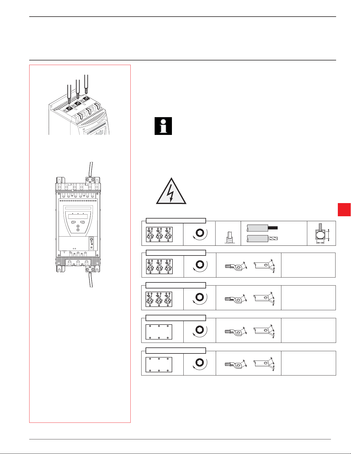
5:2.1.2 Protective earthing
Softstarters type PST85...PSTB1050 should be earthed using the terminals as shown in
Figure 5 (one connection is suffi cient).
Warning!
Do not operate machine with the grounding wire disconnected
PST 30...72
B1 B2 B3
3L2 5L3
1L1
2T1 4T2 6T3
4 mm
M8
6 Nm - 53 lb.in
1 x 6 ...... 70 mm
2 x 6 ...... 35 mm
!WG 1...8
1 x 6 ...... 70 mm
2 x 6 ...... 35 mm
2
2
2
2
14
5
14
Figure 5: Protective earthing.
PST 85...142
B1 B2 B3
3L2 5L3
1L1
2T1 4T2 6T3
PST 175...300
1L1
B1 B2 B3
3L2 5L3
2T1 4T2 6T3
PSTB 370...470
3L2
1L1
2T1 4T2 6T3
5L3
PSTB 570...1050
3L2
1L1
2T1 4T2 6T3
5L3
M8
9 Nm - 80 lb.in
M8
18 Nm - 160 lb.in
M10
40 Nm - 354 lb.in
M12
45 Nm - 443 lb.in
Figure 6: Tightening torques and cable sizes
Low Voltage Products & Systems 5.3
ABB Inc. • 888-385-1221 • www.abb-control.com 1SXU 132 021 M0201
V
Chapter 5
Connection
5:2.2 Control voltage and control circuit
N
5:2.2.1 Control voltage, terminals 1 and 2
L
Connect the hot and neutral and phase to terminals 1 and 2.
Information!
Check that you have the correct control voltage Us.
7
6
In1
5
In0
4
rt
3
Sta
2
Stop
1
100-250V
Hz
0
/6
50
Figure 7: Control voltage
5:2.2.2 Grounding, terminal 3
Connect the cable to a grounding point close to the softstarter. The cable should be as short as possible. A
suitable grounding point would be next to the softstarter on the mounting plate, see Figure 8. The mounting
plate should also be grounded.
Information!
This is not a protective ground, it is a functional ground. The grounding cable should be
as short as possible. Maximum length: 1.5 ft.
5
7
6
In1
5
In0
4
t
3
Star
1
0-250V
10
Hz
/60
50
Figure 8: Functional ground
2
Stop
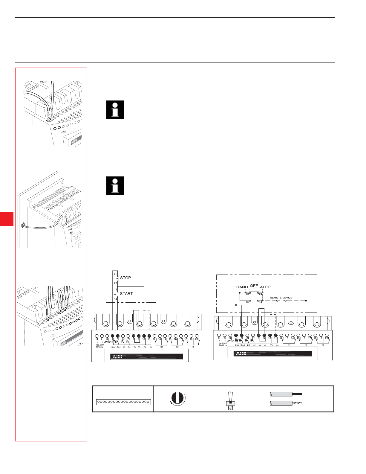
5:2.2.3 Start and Stop, terminals 4, 5, 8, 9, 10, 11
Internal control voltage
The softstarter has a built-in holding circuit which does not require any external power source for start and
stop, See Figure 10.
A conventional circuit with a HOA switch is also possible, see Figure 11.
12
11
10
p
V
9
p
V
8
n
V
7
Vc
6
1
In
5
In0
4
3
Start
p
2
Sto
1
0-250V
10
Hz
0
/6
50
Figure 9: Terminals 4, 5, 8, 9, 10, 11
Figure 10: Holding circuit (momentary start signal required)
M3
1. . . . . . . . . . . . . . . . . . . . . . . . 20
?
0,5 Nm - 4,3 lb.in
Figure 11: Conventional circuit (maintained start signal required)
3,5x0,6
0,14 ... 2,5 mm
AWG 12 ... 22
0,14 ... 2,5 mm
Figure 12: Tightening torques and cable sizes
5.4 Low Voltage Products & Systems
1SXU 132 021 M0201 ABB Inc. • 888-385-1221 • www.abb-control.com
2
2

Chapter 5
Connection
External control voltage
The softstarter can, if required, also be used with an external 24 V DC source from a PLC or similar.
Connect the cables according to Figure 13 or Figure 14 depending on which type of control method is
used.
6
5
In0
4
3
Start
2
Stop
1
0-250V
10
Hz
/60
50
Figure 15: Terminals 6, 7
Figure 14: Conventional circuit with external control voltage (maintained start signal is required)Figure 13: Holding circuit with external control voltage (momentary start signal required)
5
5:2.2.4 Programmable inputs, terminals 6 and 7
The softstarter has two programmable inputs.
In0: default, reset event
In1: default, reset event
See Chapter 7 “ Settings and confi guration” for programming.
Connect the cables according to Figure 16 or Figure 17 depending on whether the internal or external
12
11
10
Vp
9
Vp
8
n
V
7
c
V
In1
source is being used.
Information!
See next page for multiple motor (sequence) starting
Figure 16: Internal control voltage
M3
1. . . . . . . . . . . . . . . . . . . . . . . . 20
Low Voltage Products & Systems 5.5
ABB Inc. • 888-385-1221 • www.abb-control.com 1SXU 132 021 M0201
?
0,5 Nm - 4,3 lb.in
Figure 18: Tightening torques and cable sizes
3,5x0,6
Figure 17: External control voltage
0,14 ... 2,5 mm
AWG 12 ... 22
0,14 ... 2,5 mm
2
2

Chapter 5
Connection
Programmable Inputs (Sequence start)
When sequence start is going to be used, the wiring should be according to Figure 18 or Figure 19.
The start command (Terminal 5, 6 and 7) must be maintained during th complete starting sequence;
otherwise, a direct stop will be performed.
Soft stop can only be performed for the motor currently fed by the softstarter and will be achieved by
opening the Stop command (Terminal 4).
Start seq.
st
nd
Stop
1
Start seq.
Start seq.
rd
2
3
Start seq.
st
Stop
1
Start seq.
Start seq.
nd
rd
2
3
DC
+
-
5
1234567891011121314151617181920
L
N
100-250V
50/60 Hz
Start
Stop
In1 Vc Vn Vp Vp
In0
K4
K5 K6
Figure 18: Internal control voltage Figure 19: External control voltage
5:2.2.5 Programmable output relay K4, terminals 12, 13 and 14
The output relay gives a signal depending on the selected function.
Default: Run
See Chapter 7 “ Settings and confi guration” for programming.
Connect the cables to terminal 12, 13 and 14.
M3
1. . . . . . . . . . . . . . . . . . . . . . . . 20
Figure 21: Tightening torques and cable dimensions (1 mm=0,0394 in)
20
19
18
6
K
17
16
15
K5
14
13
12
11
K4
10
Vp
9
Vp
8
Vn
7
Vc
6
In1
In0
?
0,5 Nm - 4,3 lb.in
1234567891011121314151617181920
L
N
100-250V
50/60 Hz
Start
Stop
In1 Vc Vn Vp Vp
In0
K4
K5 K6
3,5x0,6
0,14 ... 2,5 mm
AWG 12 ... 22
0,14 ... 2,5 mm
2
2
Figure 20: Terminals 12, 13, 14
5.6 Low Voltage Products & Systems
1SXU 132 021 M0201 ABB Inc. • 888-385-1221 • www.abb-control.com

0
17
0
16
15
K5
14
13
12
11
K4
10
Vp
9
Vp
8
Vn
7
Vc
In1
Figure 22: Terminals 15, 16, 17
17
16
15
K5
14
13
12
11
K4
10
Vp
9
Vp
8
Vn
7
Vc
In1
Chapter 5
Connection
5:2.2.6 Programmable output relay K5, terminals 15, 16 and 17
The output relay gives a signal depending on the selected function.
Default: Top of ramp
See Chapter 7 “ Settings and confi guration” for programming.
Connect the cables to terminal 15, 16 and 17.
20
19
18
K6
5:2.2.7 Programmable output relay K6, terminals 18, 19 and 20
The output relay gives a signal depending on the selected function.
Default: Event
See Chapter 7 “ Settings and confi guration” for programming.
Connect the cables to terminal 18, 19 and 20.
20
19
18
K6
5
Figure 23: Terminals 18, 19, 20
5:2.2.8 PTC input
If the motor is protected by PTC elements, the cables must be connected to terminals PTC, see Figure 24.
1SF
A 8
94 007 R1
IEC
Us: 100
94
7-4-2
-250V AC/DC
Ie: 37
002
-72A
UL 508
72:
Ue:
Made in
Uc: 100
AC-53
I
n
lin
22
-250V AC/DC
Sw
Ov
e
FLA: 37
0-230
e
a
rload
eden
: 8-
18
380-400
-68A
C
,5
apa
1
CAU
.
6:
c
ity
Ue
1
TI
37
15
ON
500
%
of
Fu
I
C
n
se 250A
V
45
ontinuou
lin
Max
208
e
s
TYPOW
hort
kW
220-24
s
20
c
irc
uit
ER
0 44
c
urr
Z
20
IL
0-480
ent
OX
65
LISTE
k
A
50
V
at
K
IND. CONT. EQ
D 7F39
e
y
-
Pad
Hp
.
PTC
Wire 1-8 A
l
C
u
75C
only
, 35
lb
-in
FELD
B
USS
Figure 24: PTC connection
Low Voltage Products & Systems 5.7
ABB Inc. • 888-385-1221 • www.abb-control.com 1SXU 132 021 M0201
See Chapter 7 “ Settings and confi guration” for programming.
M3
1. . . . . . . . . . . . . . . . . . . . . . . . 20
?
0,5 Nm - 4,3 lb.in
Figure 25: Tightening torques and cable sizes
3,5x0,6
0,14 ... 2,5 mm
AWG 12 ... 22
0,14 ... 2,5 mm
2
2

20
19
18
K6
17
16
15
K5
14
13
12
11
K4
10
9
Vp
8
Vp
7
6
Vn
5
Vc
4
In1
3
2
In0
1
N
Start
L
Stop
100-250V
AC/DC, 50/60 Hz
B3
L3
5
B2
3L2
eden
B1
1L1
39
Made in Sw
.
V
n
i
-
6:
lb
. EQ
.
ED 7F
kW
6T3
500
ly, 35
IST
L
: 8-1
45
-400
75C on
IND. CONT
4T2
u
FELDBUSS
C
l
37
AC-53a
T1
s
V
u
2
re 1-8 A
o
72:
220-230 380
u
Wi
n
80
i
18,5
Cont
440-4
f
Ue:
o
0
%
ne
5
li
In
-4-2
y 11
1SFA 894 007
t
i
220-24
208
Capac
d
oa
l
IEC 947
er
A
Ov
Us: 100-250V AC/DC
C
X
Ue
PT
O
IL
Z
Ie: 37-72
A at
k
R
E
rrent 65
u
TYPOW
t c
UL
rcui
d
i
a
A
se 250A
ort c
Uc: 100-250V AC/DC
u
h
F
Key-P
x s
a
M
FLA: 37-68
ON
I
CAUT
Figure 26: Fieldbus plug
Chapter 5
Connection
5:3 Connection of communication devices (optional)
5:3.1 Fieldbus communication
The fi eldbus communication plug must be connected to the communication interface on the front of the PST,
see Figure 26. Make sure that the plug is in correct position and tighten the screw with 0.8 Nm (7.1 lb in) and
additional 1/4 turn.
For programming and other information, see Chapter 7 “ Settings and confi guration” and Chapter 8 “ Field-
bus communication (option)”.
Made in Sweden
PTCKey-Pad Fieldbus
5
Figure 27: Principle of a fi eldbus network with PST softstarters connected
Made in Sweden
PTCKey-Pad Fieldbus
5:3.2 External keypad
An external keypad for door mounting can be connected to the softstarter. A 3-meter cable including both the
serial communication and the power supply to the keypad makes the connection.
The external keypad can also be used for transferring parameters from one softstarter to another during
commissioning (temporarily handheld). Note that NEMA 4/4X cannot be achieved when the keypad is not
mounted.
When thee external keypad is used, both keypads will work in parallel but the softstarter keypad always has
the highest priority if the keys on both units are pressed simultaneously.
Figure 28: External keypad
5:3.3 Transferring parameters
20
19
18
K6
17
16
15
K5
14
13
12
11
K4
10
9
Vp
8
Vp
7
6
Vn
5
Vc
4
In1
3
2
In0
1
N
Start
L
op
St
0V
100-25
AC/DC, 50/60 Hz
B3
L3
5
B2
3L2
B1
Sweden
1L1
9
3
Made in
.
V
in
lb
. EQ
ED 7F
kW
6T3
T
, 35
500
ly
IS
L
45
75C on
IND. CONT
4T2
u
FELDBUSS
C
l
37
s
V
u
2T1
o
72: AC-53a: 8-1.6:
u
Wire 1-8 A
220-230 380-400
n
i
18,5
Cont
f
894 007
Ue:
440-480
o
%
ne
5
li
11
In
y
1SFA
t
220-240
i
Capac
d
208
oa
l
IEC 947-4-2
er
Ov
Us: 100-250V AC/DC
C
Ue
PT
OX
t
IL
Z
Ie: 37-72A
A a
k
R
E
rrent 65
u
TYPOW
t c
UL
ui
rc
d
a
P
-
se 250A
ort ci
Uc: 100-250V AC/DC
y
u
h
F
Ke
s
x
a
M
FLA: 37-68A
ON
I
T
CAU
Figure 29: Upload
To transfer (copy) parameters from one softstarter to another, connect the keypad to the chosen softstarter and follow the
sequence below.
5:3.3.1 Uploading parameters
Enter the menu Transfer par. Select To Keypad and confi rm by pressing Select. A text Load to Keypad will be displayed..
Continue by pressing Execute and then Yes when the text Are You Sure is displayed. Transfer OK will now be displayed
if the transmission was successful. Otherwise, Transfer Not OK will be displayed.
5.8 Low Voltage Products & Systems
1SXU 132 021 M0201 ABB Inc. • 888-385-1221 • www.abb-control.com

Figure 30: Download
Chapter 5
Connection
5:3.3.2 Downloading parameters
To download the parameters, connect the keypad to the chosen softstarter and select To Starter. A text
20
19
18
K6
17
16
15
K5
14
13
12
11
K4
10
9
Vp
8
Vp
7
6
Vn
5
c
V
4
1
n
I
3
2
0
In
1
t
tar
N
S
L
p
o
St
V
Hz
0
6
0/
5
100-250
,
DC
AC/
B3
L3
5
B2
n
3L2
e
ed
1
B
w
S
1
L
in
1
9
ade
3
M
.
V
F
7
n
i
-
3
EQ
b
6:
D
l
.
.
0
T
E
0
kW
6T
N
T
, 35
5
S
ly
O
S
I
8-1
C
S
L
5
.
4
BU
2
5C on
D
3a:
7
IND
L
4T
u
5
80-400
E
F
3
C
l
7
0
3
3
2
1
1-8 A
V
s
e
u
2T
r
i
220-
o
007
72: AC-
u
W
5
,
n
80
i
4
nt
18
o
0-
C
e:
f
44
894
U
o
%
ne
5
li
11
In
20-240
y
1SFA
2
t
i
C/DC
ac
A
8
ap
0
C
50V
2
2
d
oa
l
00-
IEC 947-4-2
1
:
ver
s
A
O
U
C
72
e
T
X
U
7-
P
O
t
3
IL
e:
Z
I
A a
k
C
R
5
D
6
E
t
C/
W
n
A
O
rre
P
u
0V
Y
c
5
T
t
i
-2
UL
u
0A
c
00
r
5
d
i
1
2
c
a
t
P
A
c:
r
-
se
8
o
U
y
u
6
h
e
F
s
K
x
37
a
:
A
M
L
F
ON
TI
CAU
Load to Start will be displayed. Continue by pressing Execute and then Yes when the text Are You Sure is
displayed. Transfer OK will now be displayed if the transmission was successful; otherwise, Transfer Not OK
will be displayed. Set the parameter Setting le and confi rm by pressing Next.
Information!
The parameters in the menu Service Settings will not be transferred.
To learn how to operate the keypad, see Chapter 6 “Human-Machine Interface (HMI)”
5:3.3.3 Technical data
Display LCD type
Signal indication LEDs Power on: Green
Protection: Yellow
Fault: Red
Ambient temperature Storage: -25°C to +70°C (-13°F to 158°F)
Operation: 0°C to +50°C (32°F to 122°F)
Degree of protection IP66
UL approval Type 1
Type 4X Indoor
Type 12
Marine approvals Contact your ABB sales offi ce
5
Low Voltage Products & Systems 5.9
ABB Inc. • 888-385-1221 • www.abb-control.com 1SXU 132 021 M0201

Notes
5
5.10 Low Voltage Products & Systems
1SXU 132 021 M0201 ABB Inc. • 888-385-1221 • www.abb-control.com

Installation and maintenance manual
PST30...PSTB1050
Overview........................................................................................................6.2
Application ............................................................................................... 6.2
Design ...................................................................................................... 6.2
Password .................................................................................................6.3
Setting password ................................................................................6.3
Wrong password ................................................................................6.3
Locking/unlocking the keypad ..................................................................6.3
Menu tree ......................................................................................................6.4
Overview ..................................................................................................6.4
Top level ...................................................................................................6.4
Settings menu ..........................................................................................6.5
Local Control menu ..................................................................................6.5
Start/Stop the motor ...........................................................................6.6
Jog ..................................................................................................... 6.6
DOL start ............................................................................................6.6
Event Log menu .......................................................................................6.7
Status Information menu ..........................................................................6.7
Reset Events menu .................................................................................. 6.7
Chapter 6
Human Machine Interface (HMI)
6
Low Voltage Products & Systems 6.1
ABB Inc. • 888-385-1221 • www.abb-control.com 1SXU 132 021 M0201

Chapter 6
Human-Machine Interface (HMI)
1
Power on ProtectionFault
Figure 1: Human-Machine Interface
1 Status indication LEDs
2 LCD display
3 Selection keys
4 Navigation keys
1
Power on ProtectionFault
Setting Ie 100A
Change Back
Power on ProtectionFault
Setting Ie 100A
Store Cancel
Figure 2: Menu examples
1 Scrolling icons
6
U = 0% I = 0.0A
Menu
Figure 3: Top level
SETTINGS
Select Back
Figure 4: SETTINGS menu
Application Setting
Select Back
Figure 5: Application Setting menu
Functional Settings
Select Back
Figure 6: Functional settings menu
Start/Stop
Select Back
Figure 7: Start/stop menu
Setting Ie 100A
Change Back
Figure 8: Setting Ie menu
Setting Ie 100A
Store Cancel
Figure 9: Setting Ie menu, changing menu
This chapter describes how the human-machine interface (keypad and display) works.
2
6:1 Overview
6:1.1 Application
The Human-Machine Interface is used for several purposes such as programming the softstarter, i.e setup of
inputs and outputs, protection functions, warning levels, fi eldbus communication, etc. The HMI is also used for
3
4
1
monitoring, local control and receiving status information from the softstarter.
6:1.2 Design
The HMI consists of:
• Status indication LED indicators
• LCD display
• Selection and Navigation keys
The LED indicators work as follows:
LED Color Description
Power on Green Control voltage connected
Fault Red Indicates faults
Protection Yellow Indicates protective function has activated
When a Fault or Protection LED is activated, the LCD displays the actual fault or protection.
The keypad is based on the same user concept as today’s mobile phones.
The LCD contains two rows with 20 characters each.
The top row presents various information depending on its state. The bottom row indicates which function is
currently selected.
A scrolling icon indicates what parameter or setting value is possible to change at the position.
The Selection keys normally have more than one function, such as selecting, changing and storing parameters.
See the text on the bottom row of the LCD.
The Navigation keys are used for navigating through the various menus to the desired setting.
When selecting from a list, the scrolling is done in a closed loop fashion.
The functionality of the keypad is illustrated by the following example:
Changing the rated motor current ( Setting I
1. You will fi nd the setting as well as a short explanation and the path to it in Chapter 10 “ Functions”.
Path in menu:
Menu/SETTINGS/Functional Settings/
Start/Stop /Setting Ie
2. The top level of the softstarter start menu looks as in Figure 3. Press the left selection key to enter the menu.
The display now appears as in Figure 4.
3. Press the left selection key to select SETTINGS. The display appears as in Figure 5.
4. Press the lower navigation key until the display appears as in Figure 6.
5. Press the left selection key to select Functional set tings. Press the left selection key to select Start/Stop,
Figure 7.
6. Press the left selection key to Change the Setting Ie, Figure 8.
The display now appears as in Figure 9.
7. Use the navigation keys to set the rated current. If you want to quit, you select Cancel, using the right selec-
tion key. Otherwise, you store the new setting by selecting Store with the left selection key. The display should
now appear as in Figure 10.
8. Press the right selection key four times to return to top level.
).
e
Setting Ie 99.5A
Change Back
Figure 10: Setting Ie menu, changing setting
6.2 Low Voltage Products & Systems
1SXU 132 021 M0201 ABB Inc. • 888-385-1221 • www.abb-control.com

Change Password
Select Back
Figure 11: Change password
New Password 1
Store Back
Figure 12: New password
New Password 1
Next
Figure 13: New password stored
Chapter 6
Human-Machine Interface (HMI)
6:1.3 Password
To lock the keypad from control and change of settings, a password can be set. When the keypad is locked, all
menus are available but no changes or actions can be initiated.
6:1.3.1 Setting password
The default password is always 1.
1 Press the upper navigation key once to enter the parameter Change Password.
2 Select Change Password, Figure 11
3 Set the new password (No or 1...255) using the navigation keys.
Select Store and Next, Figure 12 and Figure 13.
Select Back to return to top level.
Wrong Password
Next
Figure 14: Wrong password
Support Code 1
Next
Figure 15: Support code
Keypad is Active
Lock
Figure 16: Keypad is menu
Keypad is Locked
Unlocked Back
Figure 17: Locked keypad menu
6:1.3.2 Wrong password
If an incorrect password is entered, the text “Wrong Password” will be displayed, Figure 14.
A support code will be given, Figure 15. The code can be ignored and an unlimited number of attempts can be
made.
If you are unable to unlock the keypad, note the support code and contact your local ABB sales offi ce.
6:1.4 Locking/unlocking the keypad
1 Press the upper navigation key twice to enter the parameter Keypad is Figure 16. The keypad is unlocked if
the display indicates Active in the upper right corner.
2 Lock the keypad
Select Lock.
Enter the correct password.
Select Enter. Keypad is now locked.
Select Back to return to top level.
3 Unlock the keypad.
Select Unlock.
Enter the correct password.
Select Enter. The keypad is now active.
Select Back to return to top level.
6
Low Voltage Products & Systems 6.3
ABB Inc. • 888-385-1221 • www.abb-control.com 1SXU 132 021 M0201

Chapter 6
Human-Machine Interface (HMI)
6:2 Menu tree
6:2.1 Overview
The menu tree includes menus for:
• Settings
• Local Control
• Event Log
• Status information
• Reset events
Top level
6
Settings
Local Control
Event Log
Status Information
Reset Events
Application setting
Basic settings
Functional settings
Presentation settings
Service settings
All settings
Changed settings
Reset all settings
Operation mode
Start / Stop
Jog
DOL Start
Figure 18: Menu tree
Start / Stop
Protections
Warnings
Faults
Inputs
Outputs
Fieldbus
Seq. Start
Top level
Settings
Local Control
Event Log
Status Information
Reset Events
Figure 19: Top level
6:2.2 Top Level
Top Level contains general softstarter information, and the menus can be reached from
here.
Use the navigation keys to cycle through the various menus.
Press Select to enter a menu.
Press Back to return to previous state
Menu Description
Settings Set up softstarter parameters
Local control Control the softstarter
Event log
Status Information Present various information
Reset Events Reset of events
Present the Event Log, faults, protections,
warnings
6.4 Low Voltage Products & Systems
1SXU 132 021 M0201 ABB Inc. • 888-385-1221 • www.abb-control.com

Chapter 6
Human-Machine Interface (HMI)
Top level
Top level
Settings
Local Control
Event Log
Status Information
Reset Events
Figure 20: Settings menu
Settings
Local Control
Event Log
Status Information
Reset Events
Figure 21: Local control menu
Application setting
Basic settings
Functional settings
Presentation settings
Service settings
All settings
Changed settings
Reset all settings
Operation mode
Start / Stop
Jog
DOL Start
6:2.3 Settings menu
The settings menu is used to set up the softstarter parameters for various applications.
Use the navigation keys to cycle through the various sub menus.
Function Description
Application setting Predefi ned parameters for typical ap-
Basic settings The basic and most used start/stop
Functional settings Language, date, time, etc.
Service settings Service and repair settings
All settings A list with all possible settings
Changed settings A list of all changed settings
Reset all settings Reset all settings to factory default
Operation mode Test mode for softstarter
plications
settings
settings
Figure 20: Settings menu
6:2.4 Local Control menu
The Local Control menu is used to start or stop the motor from the keypad. When local con-
trol is selected, the softstarter can only be controlled by the keypad.
The previous type of control is activated when exiting local control.
Three different selections are possible (see the table below).
Press navigation keys to view different types of local control.
Information!
The LOCAL CONTROL menu can not be entered if Sequence start is selected.
Once the motor has been started in this menu, it must fi rst be stopped before you leave the
menu. If the motor is already running when the menu is entered, it is possible to leave the
menu without stopping the motor.
Function Description
Start/stop To start and stop the motor with the
Jog To run the motor as long as Jog is
DOL start
(PSTB370...PSTB1050 only)
keypad
pressed
To start and stop the motor with the built-
in by-pass contactor. (See Chapter 3 for
AC3 ratings.)
Figure 21: Local control menu
6
Low Voltage Products & Systems 6.5
ABB Inc. • 888-385-1221 • www.abb-control.com 1SXU 132 021 M0201

Chapter 6
Human-Machine Interface (HMI)
6
Top level
Top level
Top level
Settings
Local Control
Event Log
Status Information
Reset Events
Figure 22: Start/Stop menu
Settings
Local Control
Event Log
Status Information
Reset Events
Figure 23: Jog menu
Settings
Local Control
Event Log
Status Information
Reset Events
Figure 24: DOL start menu
Start / Stop
Jog
DOL Start
Start / Stop
Jog
DOL Start
Start / Stop
Jog
DOL Start
6:2.4.1 Start/Stop the motor
Start
Enter the Start/Stop menu, Figure 22.
Select Start. The motor will now start and run according to the set parameters.
Stop
Select Stop. The motor will stop according to the set parameters. It is possible to press the stop
command during the start ramp if necessary.
6:2.4.2 Jog
Enter the Jog menu, Figure 23.
Select Jog. The motor will start and accelerate to rated speed according to the set parameters as
long as the Jog command is activated.
The motor stops immediately as soon as the command is released.
6:2.4.3 DOL start
(PSBT370...1050 only)
Start from the softstarter
If necessary, the motor can be started DOL (Direct On Line/across the line) with the integrated by-
pass contactor.
Select the DOL start menu, Figure 24.
Select DOL start to close the integrated by-pass contactor.
Select Stop to open the contactor.
!
Warning!
The rated motor current must never exceed the AC-3 rating of the integrated by-pass contactor.
See Chapter 3 for AC3 ratings.
100-250V
50/60 Hz
8
Figure 25: Connection when the contactor is operated
from the keypad (factory wiring).
Figure 26: Connection when the by-pass contactor is operated
separately (emergency DOL)
8
6.6 Low Voltage Products & Systems
1SXU 132 021 M0201 ABB Inc. • 888-385-1221 • www.abb-control.com

Chapter 6
Human-Machine Interface (HMI)
Top level
Top level
Settings
Local Control
Event Log
Status Information
Reset Events
Figure 25: Event log menu
Settings
Local Control
Event Log
Status Information
Reset Events
Figure 26: Status information menu
6:2.5 Event Log menu
The Event Log menu is used to check the event log in the softstarter. When entering this menu, the
twenty latest events in the log are presented, in chronological order with the latest event as No. 1,
the second latest as No. 2 etc.
The events are presented with “type of event”, date and time.
Use the navigation keys to view all entries in the event log.
6:2.6 Status Information menu
The Status information menu is used to present various information.
Use the navigation keys to cycle through the various sub menus.
If the unit is connected “inside delta”, the displayed phase currents, L1, L2 & L3 are inside delta cur-
rent values.
Display text Function
Frequency Measured frequency
Phase seq Phase sequence indication
Connection Type of connection, In Line/Inside Delta
Phase L1 Phase current L1
Phase L2 Phase current L2
Phase L3 Phase current L3
Run time Total run time of the motor
No. of Starts Run counter
SW Ver. CU Software version CU.
SW Ver. FU Software version FU.
SW Ver KP 1
DB Version Database version
MAC Address Internal addressing
LV Board No Serial No of the LV PCB
Software version External Keypad
6
1 Only if connected.
Top level
Settings
6:2.7 Reset Events menu
The Reset Events menu is entered automatically when a fault has occurred or a protection is acti-
vated. It can also be entered through the main menu.
Local Control
Event Log
Status Information
Reset Events
Figure 27: Reset events menu
Low Voltage Products & Systems 6.7
ABB Inc. • 888-385-1221 • www.abb-control.com 1SXU 132 021 M0201
Use the navigation keys to view all events. Each event can be reset.

Notes
6
6.8 Low Voltage Products & Systems
1SXU 132 021 M0201 ABB Inc. • 888-385-1221 • www.abb-control.com

Installation and maintenance manual
PST30...PSTB1050
Settings ............................................................................................................... 7.2
Overview of all accessible settings (different menus) ............................7.3 - 7.7
Description of menus ........................................................................................... 7.8
Top level .........................................................................................................7.8
Application Setting ...............................................................................7.9 - 7.10
Basic Settings .............................................................................................. 7.10
Functional Settings .......................................................................................7.11
Start/Stop ................................................................................................7.11
Protections ...................................................................................7.12 - 7.13
Warnings ................................................................................................7.14
Faults ...........................................................................................7.14 - 7.15
Inputs ..................................................................................................... 7.16
Outputs ................................................................................................... 7.17
Sequence start .............................................................................7.18 - 7.19
Presentation Settings ................................................................................... 7.20
Service Settings ...........................................................................................7.21
All Settings ...................................................................................................7.21
Changed Settings ................................................................................... 7.21
Reset all Settings ................................................................................... 7.22
Operation (test) mode ............................................................................ 7.22
Changed settings ................................................................................... 7.23
Reset all settings .................................................................................... 7.23
Chapter 7
Settings and confi guration
7
Low Voltage Products & Systems 7.1
ABB Inc. • 888-385-1221 • www.abb-control.com 1SXU 132 021 M0201

Chapter 7
Settings and confi guration
7:1 Settings
Settings can be done in three different ways:
• Keypad
• Fieldbus communication
• External keypad (optional)
With the keypad, settings can be done as individual parameter settings or by selecting pre-
defi ned parameters for different applications.
The unit has one complete set of parameters but some parameters have extra settings (i.e.,
sequence start). All default parameters are stored in the unit in case a full reset to default values
is required. When the fi eldbus communication is selected, most parameters can also be modifi ed
from this interface.
!
The motor may start unexpectedly if there is a start signal present when doing any of the actions
listed below:
• Switching from one type of control to another (fi eldbus control / hardware control)
• Re-programmming the programmable inuts
• Reset all Settings (programmable input set to Enable).
Caution!
7
7.2 Low Voltage Products & Systems
1SXU 132 021 M0201 ABB Inc. • 888-385-1221 • www.abb-control.com

Chapter 7
Settings and confi guration
7:1.1 Overview of all accessible settings (different menus)
Top
Setting/parameter
Password X
Keypad lock/unlock X
Reset to factory default setting X
Application type X
Setting le X X X X
Overload class X X X X
External By-pass X X X X
Start ramp Tune Set X X X
Stop ramp Tune Set X X X
Initial voltage Tune Set X X X
End voltage Tune Set X X X
Step down voltage Tune Set X X X
Current limit Tune Set X X X
Kick start XX
Kick level XX
Kick time XX
Start range XX
Stop range XX
Overload protectcion X X
Overload start class X X
Overload run class XX
Overload operation XX
Locked rotor protection X X
Locked rotor protection level X X
Locked rotor protection time X X
Locked rotor protection operation X X
Underload protection X X
Underload protection level X X
Underload protection time X X
Underload protection operation X X
Phase imbalance protection X X
Phase imbalance protection level X X
Phase imbalance protection operation X X
High current protection X X
High current protection operation X X
Phase reversal protection X X
Phase reversal protection operation X X
PTC protection XX
PTC protection operation X X
By-pass fault operation X X
Warning high current X X
Warning high current level X X
Warning low current X X
Warning low current level X X
Warning overload XX
Warning overload level X X
Warning thyristor (SCR) overload X X
Phase loss fault operation X X
Fieldbus fault operation X X
Frequency fault operation X X
level
Application
setting
Basic
settings
Functional
settings
Presentation
settings
All
settings
Reset all
settings
7
Low Voltage Products & Systems 7.3
ABB Inc. • 888-385-1221 • www.abb-control.com 1SXU 132 021 M0201

Chapter 7
Settings and confi guration
7:1.1 Overview of all accessible settings (different menus) cont.
Top
Setting/parameter
Heat sink over-temperature operation X X
Shorted thyristor (SCR) fault operation X X
Programmable input, In0 X X
Programmable input, In1 X X
Programmable output relay, K4 X X
Programmable output relay, K5 X X
Programmable output relay, K6 X X
Programmable software output, V7 X X
Event for relay K4 XX
Event for relay K5 XX
Event for relay K6 XX
Event for SW output V7 X X
Fieldbus control XX
Fieldbus type XX
Fieldbus address XX
No. of sequences (sequence start) X X
1st Setting Ie XX
2nd Setting Ie XX
3rd Setting Ie XX
Start ramp 1 XX
Start ramp 2 XX
Start ramp 3 XX
Initial voltage 1 XX
Initial voltage 2 XX
Initial voltage 3 XX
Current limit 1 XX
Current limit 2 XX
7
Current limit 3 XX
Language XX
LCD auto off XX
Date type XX
Date year XX
Date month XX
Date day XX
Time hour XX
Time minutes XX
level
Application
setting
Basic
settings
Functional
settings
Presentation
settings
All
settings
Reset all
settings
7.4 Low Voltage Products & Systems
1SXU 132 021 M0201 ABB Inc. • 888-385-1221 • www.abb-control.com

Chapter 7
Settings and confi guration
7:1.1 Overview of all accessible settings (different menus) cont.
Description
Setting current Setting Ie 9.0...1207A Individual
Time for start ramp Start Ramp 1...30s, 1...120s 10s
Time for stop ramp Stop Ramp 0...30s, 0...120s 0s
Initial voltage for start ramp Init Volt 30...70% 30%
End voltage for stop ramp End Volt 30...70% 30%
Step down voltage Step down 30...100% 100%
Level of the current limit Current Lim 2.0...7.0xle 4.0xle
Selection of kick start Kick Start Yes, No No
Level of kick start Kick Level 50...100% 50%
Time for kick start Kick Time 0.1...1.5s 0.2s
Range for start ramp Start Range 1-30s, 1-120s 1-30s
Range for stop ramp Stop Range 0-30s, 0-120s 0-30s
Overload protection Overload No, Normal, Dual Normal
Overload class OL Class 10A, 10, 20, 30 10
Overload class, Dual type, Start class OL Class S 10A, 10, 20, 30 10
Overload class, Dual type, Run class OL Class R 10A, 10, 20, 30 10
Type of operation for overload protection OL Op
Locked rotor protection Locked Rotor Yes, No No
Trip level for locked rotor protection Lock R Lev 0.5...8.0xle 4.0xle
Trip time for locked rotor protection Lock R Time 0.2...10s 1.0s
Type of operation for locked rotor protection Lock R Op
Underload protection Underload Yes, No No
Trip level for underload protection Underl Lev 0.4...0.8xle 0.5xle
Trip time for underload protection Underl Time 1...30s 10s
Type of operation for underload protection Underl Op
Phase imbalance protection Phase Imb Yes, No No
Trip level for phase imbalance protection Ph Imb Lev 10...80% 80%
Type of operation for imbalance protection Ph Imb Op
High current protection High I Yes, No No
Type of operation for high current protection High I Op
Phase reversal protection Phase Rev Yes, No No
Type of operation for phase reversal protection Ph Rev Op
PTC protection PTC Yes, No No
Type of operation for PTC protection PTC Op Stop-M, Stop-A, Ind Stop-M
Use of external by-pass contactor Ext ByPass Yes, No No
Type of operation, by-pass doesn’t open BP Closed Op Stop-M, Stop A Stop-M
Type of operation, by-pass doesn’t close BP Open Op Stop-M, Stop A Stop-M
High current warning Warn I=High Yes, No No
Trip level for high current warning Wa I=H Lev 0.5...5.0xle 1.2xle
Low current warning Warn I=Low Yes, No No
Trip level for low current warning Wa I=L Lev 0.4...1.0xle 0.8xle
Motor overload warning Warn OL Yes, No No
Trip level for motor overload warning Wa OL Lev 40...99% 90%
Thyristor overload warning Warn SCR OL Yes, No No
Type of operation for phase loss fault Ph Loss Op Stop-M, Stop-A Stop-M
Type of operation for fi eldbus fault FB Fault Op Stop-M, Stop-A Stop-M
Type of operation for frequency fault Freq F Op Stop-M, Stop-A Stop-M
Type of operation for heatsink overtemp fault HS Temp Op Stop-M, Stop-A Stop-M
Type of operation for shorted thyristor fault SCR SC Op Stop-M, Stop-A Stop-M
Function of programmable input In0 In0
Display
text
Setting
range
Stop-M, Stop-A, Ind
Stop-M, Stop-A,
Stop-M, Stop-A, Ind
Stop-M, Stop-A, Ind
Stop-M, Stop-A, Ind
Stop-M, Stop-A, Ind
None, Reset,
Enable Jog, DOL,
Start 2, FB-Dis
Ind Stop-M
Default
value
Stop-M
Stop-M
Stop-M
Stop-M
Stop-M
Reset
Actual
setting
7
Low Voltage Products & Systems 7.5
ABB Inc. • 888-385-1221 • www.abb-control.com 1SXU 132 021 M0201

Chapter 7
Settings and confi guration
7:1.1 Overview of all accessible settings (different menus) cont.
Description
Function of programmable input In1 In1
Function of programmable output relay K4 Relay K4 Run, TOR, Event Run
Function of programmable output relay K5 Relay K5 Run, TOR, Event TOR
Function of programmable output relay K6 Relay K6 Run, TOR, Event Event
Function of programmable software relay V7 SW Outp V7 Run, TOR, Event Event
Overload event of relay K4 K4 Overload Yes, No No
Fault event of relay K4 K4 Fault Yes, No No
Shunt fault of relay K4 K4 Shunt Fault Yes, No No
High current event of relay K4 K4 High I Yes, No No
Thyristor overload event of relay K4 K4 SCR OL Yes, No No
Locked rotor event of relay K4 K4 Lock Rot Yes, No No
Underload event of relay K4 K4 Underload Yes, No No
Phase imbalance event of relay K4 K4 Phase Imb Yes, No No
PTC event of relay K4 K4 PTC Yes, No No
Phase reversal event of relay K4 K4 Phase Rev Yes, No No
Warning motor overload event of relay K4 K4 Warn OL Yes, No No
Warning thyristor overload event of relay K4 K4 Wa SCR OL
Warning high current event of relay K4 K4 Wa I=High Yes, No No
Warning low current event of relay K4 K4 Wa I=Low Yes, No No
Overload event of relay K5 K5 Overload Yes, No No
Fault event of relay K5 K5 Fault Yes, No No
Shunt fault of relay K5 K5 Shunt Fault Yes, No No
High current event of relay K5 K5 High I Yes, No No
Thyristor overload event of relay K5 K5 SCR OL Yes, No No
Locked rotor event of relay K5 K5 Lock Rot
Underload event of relay K5 K5 Underload Yes, No No
Phase imbalance event of relay K5 K5 Phase Imb Yes, No No
PTC event of relay K5 K5 PTC
7
Phase reversal event of relay K5 K5 Phase Rev Yes, No No
Warning motor overload event of relay K5 K5 Warn OL
Warning thyristor overload event of relay K5 K5 Wa SCR OL Yes, No No
Warning high current event of relay K5 K5 Wa I=High
Warning low current event of relay K5 K5 Wa I=Low Yes, No No
Overload event of relay K6 K6 Overload Yes, No Yes
Fault event of relay K6 K6 Fault Yes, No Yes
Shunt fault of relay K6 K6 Shunt Fault Yes, No Yes
High current event of relay K6 K6 High I Yes, No Yes
Thyristor overload event of relay K6 K6 SCR OL Yes, No No
Locked rotor event of relay K6 K6 Lock Rot Yes, No No
Underload event of relay K6 K6 Underload Yes, No No
Phase imbalance event of relay K6 K6 Phase Imb Yes, No No
PTC event of relay K6 K6 PTC Yes, No No
Phase reversal event of relay K6 K6 Phase Rev Yes, No No
Warning motor overload event of relay K6 K6 Warn OL Yes, No No
Warning thyristor overload event of relay K6 K6 Wa SCR OL Yes, No No
Warning high current event of relay K6 K6 Wa I=High Yes, No No
Warning low current event of relay K6 K6 Wa I=Low Yes, No No
Overload event of relay V7 V7 Overload Yes, No Yes
Fault event of relay V7 V7 Fault Yes, No Yes
High current event of relay V7 V7 High I
Thyristor overload event of relay V7 V7 SCR OL
Locked rotor event of relay V7 V7 Lock Rot
Underload event of relay v7 V7 Underload
Phase imbalance event of relay V7 V7 Phase Imb
Display
text
Setting
range
None, Reset,
Enable Jog, DOL,
Start 3, FB-Dis
Yes, No
Yes, No
Yes, No
Yes, No
Yes, No
Yes, No
Yes, No
Yes, No
Yes, No
Yes, No
Default
value
Reset
No
No
No
No
No
Yes
No
No
No
No
Actual
setting
7.6 Low Voltage Products & Systems
1SXU 132 021 M0201 ABB Inc. • 888-385-1221 • www.abb-control.com

Chapter 7
Settings and confi guration
7:1.1 Overview of all accessible settings (different menus) cont.
Description
PTC event of relay V7 V7 PTC Yes, No No
Phase reversal event of relay V7 V7 Phase Rev Yes, No No
Warning motor overload event of relay V7 V7 Warn OL Yes, No No
Warning thyristor overload event of relay V7 V7 Wa SCR OL Yes, No No
Warning high current event of relay V7 V7 Wa I=High Yes, No No
Warning low current event of relay V7 V7 Wa I=Low Yes, No No
Control of the softstarter with the fi eldbus Fieldb Ctrl Yes, No No
Type of fi eldbus protocol used Fieldb Type AS-Int, Other Other
Fieldbus address Fieldb Addr 0...1000 0
Number of sequences for sequence start No of Seq No, 2, 3 No
1st sequence, time for start ramp Start Ramp 1 1...30s, 1...120s 10s
1st sequence, initial voltage for start ramp Init Volt 1 30...70% 30%
1st sequence, current limit level Curr Lim 1 2.0...7.0xle 4.0xle
1st sequence, setting current 1st Set le 9.0...1207A Individual
2nd sequence, time for start ramp Start Ramp 2 1...30s, 1...120s 10s
2nd sequence, initial voltage for start ramp Init Volt 2 30...70% 30%
2nd sequence, current limit level Curr Lim 2 2.0...7.0xle 4.0xle
2nd sequence, setting current 2st Set le 9.0...1207A Individual
3rd sequence, time for start ramp Start Ramp 3 1...30s, 1...120s 10s
3rd sequence, initial voltage for start ramp Init Volt 3 30...70% 30%
3rd sequence, current limit level Curr Lim 3 2.0...7.0xle 4.0xle
3rd sequence, setting current 3st Set le 9.0...1207A Individual
Language to use on the display Language
Time for display automatic turn off LCD Auto Off 1...255min 15min
Type of date presentation Date Type ISO, CE, US ISO
Year Date Year 2001...2060 Individual
Month Date Month 1...12 Individual
Day Date Day 1...31 Individual
Hour Time Hour 0...23 Individual
Minutes Time Min 0...59 Individual
Display
text
Setting
range
US/UK, FI, SE, PT,
NL, IT, FR, ES, DE,
CN, RU, TR
Default
value
Indiividual
Actual
setting
7
Low Voltage Products & Systems 7.7
ABB Inc. • 888-385-1221 • www.abb-control.com 1SXU 132 021 M0201

Chapter 7
Settings and confi guration
Change Password
Select Back
Keypad is Active
Lock Back
2003-01-30 11:08
Back
7
U=†††0% †I=0.0A
Menu
Uin † OK
Back
Motor Temp 0%
Back
SCR Temp 60%
Back
In=0000 Out = 0000
Back
Figure 1: Top level display loop
5 )!
-ENU
Figure 2: Top level (start position)
2003-02-05 10:33
Back
Figure 3: Real time clock
Uin OK
Back
Figure 4: U
status
in
Motor Temp 0%
Back
Figure 5: Motor temperature
In = 0000 Out = 0000
Back
Figure 6: Input/outputs
7:2 Description of menus
For detailed description of each function, see Chapter 10 “ Functions” .
7:2.1 Top level
This level contains information about output voltage, current, heat sink temperature, real time clock
and more. From this menu, the keypad can be locked/unlocked and a password can be set. It is
also possible to enter all top level menus.
Display at start up
When switching on the control voltage, the LCD will fi rst display the text “Hello”, and after a few
seconds switch to the Top Level start position, Figure 2.
Real time clock
The real time clock displays the present date and time. To set date, time and display types, see
“Presentation Settings.”
Uin status
The softstarter checks and displays the status of the input voltage (line side).
Motor temperature
The consumed thermal capacity of the motor is displayed. 0% means that the motor is in cold state.
50% means that half the capacity is consumed, etc.
Status of inputs/outputs
The status of the Programmable inputs and outputs is displayed with “0” for not activated or “1” for
activated. The fi gures have the following functions:
In=0100 Start signal high
In=1000 Stop signal high
In=0010 In0 high
In=0001 In1 high
Out=1000 Relay K4 activated
Out=0100 Relay K5 activated
Out=0010 Relay K6 activated
Out=0001 SW V7 activated
SCR Temp 60%
Back
Figure 7: SCR temperature
Keypad is Active
Back
Figure 8: Keypad status
Change Password
Select Back
Figure 9: Change Password
SCR Temperature
The temperature of the SCRs in the softstarter is displayed as a percentage of the maximum value.
Keypad status
Information on whether the keypad is locked or unlocked. How to operate, see Chapter 6 “Human-
Machine Interface (HMI)”.
Change Password
Menu for changing the password, How to operate, see Chapter 6 “Human-Machine Interface (HMI)”.
7.8 Low Voltage Products & Systems
1SXU 132 021 M0201 ABB Inc. • 888-385-1221 • www.abb-control.com

Chapter 7
Settings and confi guration
Top level
Settings
Figure 10: Application setting menu
Application setting
Basic settings
Functional settings
Presentation settings
Service settings
All settings
Changed settings
Reset all settings
Operation mode
Application Setting
Select
Figure 11: Application setting menu
Centrifugal Pump
Store Set Back
Figure 12: Application type
Centrifugal Pump
Next Back
Figure 13: Confi rming application type
7:2.2 Application Setting
The Application setting menu consists of predefi ned parameters for the selected applica-
tion and should be used if an easy and quick set-up is required. Only a few parameters
need to be set to allow the start of the motor. All necessary input data will show up in an
automatic loop.
Enter the Application setting
Enter the menu by selecting Application Setting.
Select what type of application the softstarter is used for by pressing Store Set. If the
desired application is not listed, select the one closest to the application and choose Tune
Set (see below). Possible applications are:
• Centrifugal Pump
• Hydraulic Pump
• Centrifugal Fan
• Axial Fan
• Compressor
• Conveyor
• Crusher
• Mixer
• Bow Thruster
Confi rm the selected application by pressing Next. If the wrong application type was
selected, press Back and select the correct type.
Setting Ie 100A
Store
Figure 14: Setting Ie menu
Setting Ie 100A
Next Back
Figure 15: Confi rming Setting Ie
OL Class 10
Store
Figure 16: Overload class
OL Class 10
Next Back
Figure 17: Confi rming OL Class
Ext ByPass Yes
Store
Figure 18: External By-Pass
Ext ByPass Yes
Next Back
Figure 19: Confi rming External By-Pass
Ready?
Yes Tune Set
Figure 20: Ready?/Tune Set menu
Setting I
Set the motor full load current (i.e. rated motor current if the unit is connected In Line).
For units connected Inside Delta, the Setting Ie must be set according to the current in the
delta circuit = 58% (1/( 3)) of the rated motor current.
Press Store to save the data after setting the current.
Confi rm the Setting Ie by pressing Next. If the wrong value is set, press Back and set the
correct value.
(motor FLA)
e
Overload class ( OL Class)
Select the desired overload class. Available classes:
• 10A
• 10
• 20
• 30
Press Store to save the selected class.
Confi rm the selected overload class by pressing Next. If the wrong overload class was
selected, press Back and select the correct class.
External By-Pass contactor ( Ext ByPass)
If an External Bypass contactor is used, set the parameter to Yes, otherwise select No.
Press Store to save the data.
Confi rm the selection of external by-pass by pressing Next. If the wrong selection was
made, press Back and correct the selection.
Tune Set
The confi guration of the application setting menu is now complete. If no tuning of the set-
tings is desired, it is possible to return to the top level by pressing Yes.
If tuning some parameters is desired, select Tune Set.
7
Low Voltage Products & Systems 7.9
ABB Inc. • 888-385-1221 • www.abb-control.com 1SXU 132 021 M0201

Ready?
Yes Back
Figure 21: All tuning parameters have been passed
Top level
Settings
Figure 22: Basic Settings menu
Chapter 7
Settings and confi guration
Tuning parameters
Six parameters can be tuned individually if a more specifi c adjustment is required. Each
parameter is described in Chapter 10 “ Functions” .
• Start ramp
• Stop ramp
• Initial voltage
• End voltage
• Step down voltage
• Current limit level
When all tuning parameters have been cycled through, the following information will be
displayed, Figure 21. Select Yes if all necessary parameters are tuned. If a new tuning is
required, select Back and follow the step Tune Set above
Application setting
Basic settings
Functional settings
Presentation settings
Service settings
All settings
Changed settings
Reset all settings
Operation mode
7:2.3 Basic Settings
The Basic settings menu consists of the most common start/stop parameters required for
the set-up. Each parameter can be adjusted separately. For a detailed description of each
parameter, see Chapter 10 “ Functions” .
Enter the Basic settings
Enter the menu by selecting Basic Settings.
Setting Ie (motor FLA)
Set the current that the softstarter will be exposed to (i.e. rated motor current, if the unit is
connected In Line).
Information!
For units connected Inside Delta the Setting Ie must be set according to the current in the
delta circuit = 58% (1/( 3)) of the rated motor current. Press Store to save the data after
setting the current
External By-Pass contactor ( Ext ByPass)
Set the parameter to Yes if an External By-pass Contactor is used, otherwise select No.
7
Start ramp
Set the ramp time for start.
Stop ramp
Set the ramp time for stop (softstop). Note that this function should only be used for
applications with small fl ywheel masses, for example pumps and conveyors (minimizes
product damage during the stop).
Initial voltage ( Init Volt)
Set the initial voltage level.
End voltage ( End Volt)
Set the end voltage level.
Step down
Set the level of the step down voltage. This function is only present if softstop is selected.
Current limit ( Current Lim)
Set the current limit level for the start.
Overload Class ( OL Class)
Select the desired overload class.
The confi guration of the basic setting menu is now completed. It is possible to return to
the top level by pressing Back 3 times.
7.10 Low Voltage Products & Systems
1SXU 132 021 M0201 ABB Inc. • 888-385-1221 • www.abb-control.com

Chapter 7
Settings and confi guration
Top level
Settings
Settings
Figure 23: Functional Settings menu
Functional settings
Figure 24: Start/Stop group
Application setting
Basic settings
Functional settings
Presentation settings
Service settings
All settings
Changed settings
Reset all settings
Operation mode
Start / Stop
Protections
Warnings
Faults
Inputs
Outputs
Fieldbus
Seq. Start
7:2.4 Functional Settings
The Functional setting menu consists of groups with parameters arranged by function
such as protection, warning, fault, fi eldbus communication etc. This menu should be
used if a more advanced set-up is required. For a detailed description of each parameter, see Chapter 10 “ Functions” .
Enter the Functional settings
Enter the menu by selecting Functional Settings.
7:2.4.1 Start/Stop
To set parameters related to start and stop, enter the Start/Stop group. The following
parameters are available in this group:
• Setting I
• External By-Pass
• Start ramp
• Stop ramp
• Initial voltage
• End voltage
• Step down voltage
• Current limit level
• Kick start
• Kick level
• Kick time
• Start range
• Stop range
e
To set parameters from Setting Ie to Current limit level, see “Basic Settings”.
Kick Start
Activate the Kick Start function by entering this menu. Press Store to save the
selection.
Kick Level
Set the required level of the Kick Start. Press Store to save the data.
This menu will only be visible if Kick Start is activated.
Kick Time
Set the required time for the kick start. Press Store to save the data.
This menu will only be visible if Kick Start is activated.
Start Range
The ramp time for start can be set between 1 and 30 seconds as default. If required,
the range can be extended up to 120 seconds by entering this menu. Press Store to
save the data.
Stop Range
The ramp time for stop can be set between 0 and 30 seconds as default. If required,
the range can be extended up to 120 seconds by entering this menu. Press Store to
save the data.
The confi guration of the parameters in the Start/Stop group is now completed. It is pos-
sible to return to top level by pressing Back three times. To confi gure the protections,
proceed to that menu.
7
Low Voltage Products & Systems 7.11
ABB Inc. • 888-385-1221 • www.abb-control.com 1SXU 132 021 M0201

Chapter 7
Settings and confi guration
7
Settings
Functional settings
Figure 25: Protections group
Start / Stop
Protections
Warnings
Faults
Inputs
Outputs
Fieldbus
Seq. Start
7:2.4.2 Protections
To set parameters related to the protections, enter the Protections group.
Overload
Select the required overload type for the application. The following selections are available:
• No
• Normal
• Dual
Press Store to save the selected type.
If overload “Normal” is selected, the following settings will be available:
Overload class ( OL Class)
Select the overload class. Following classes are available:
• 10A
• 10
• 20
• 30
Press Store to save the selected class.
Overload type of operation ( OL Op)
Select what operation should be initiated if the overload relay is activated:
Stop–M The motor will stop and a manual reset is required.
Stop–A The motor will stop and an automatic reset is performed.
Ind Only indication will be given.
Press Store to save the selected operation.
If overload “Dual” is selected, the following settings will be available:
Overload start class ( OL Class S)
Select the required overload class during start condition. The following overload classes
are available:
• 10A
• 10
• 20
• 30
Press Store to save the selected class.
Overload run class ( OL Class R)
Select the required overload class during continuous run. The following overload classes
are available:
• 10A
• 10
• 20
• 30
Press Store to save the selected class.
Locked Rotor
Activate the protection if required by changing to Yes.
If “Yes” is selected, the following settings will be available:
Locked rotor level (Lock R Lev)
Set the level of the locked rotor protection.
Available only if the protection is selected.
Locked rotor time ( Lock R Time)
Set the time for the locked rotor protection.
Available only if the protection is selected.
Locked rotor type of operation ( Lock R Op)
Select what operation should be initiated if the locked rotor protection is activated:
Stop–M The motor will stop and a manual reset is required.
Stop–A The motor will stop and an automatic reset is performed.
Ind Only indication will be given.
Press Store to save the selected operation.
7.12 Low Voltage Products & Systems
1SXU 132 021 M0201 ABB Inc. • 888-385-1221 • www.abb-control.com

Chapter 7
Settings and confi guration
Underload
Activate the protection if required by changing to Yes.
If “Yes” is selected, the following settings will be available:
Underload level ( Underl Lev)
Set the level of the underload protection.
Available only if the protection is selected.
Underload time ( Underl Time)
Set the time for the underload protection.
Available only if the protection is selected.
Underload type of operation ( Underl Op)
Select what operation should be initiated if the underload protection is activated:
Stop–M The motor will stop and a manual reset is required.
Stop–A The motor will stop and an automatic reset is performed.
Ind Only indication will be given.
Press Store to save the selected operation.
Phase imbalance ( Phase Imb)
Activate the protection if required by changing to Yes.
If “Yes” is selected, the following settings will be available:
Phase imbalance level (Ph Imb Lev)
Set the level of the phase imbalance protection.
Available only if the protection is selected.
Phase imbalance type of operation ( Ph Imb Op)
Select what operation should be initiated if the phase imbalance protection is activated:
Stop–M The motor will stop and a manual reset is required.
Stop–A The motor will stop and an automatic reset is performed.
Ind Only indication will be given.
Press Store to save the selected operation.
High current ( High I)
Activate the high current protection if required by changing to Yes.
If “Yes” is selected, the following setting will be available:
High current type of operation ( High I Op)
Select what operation should be initiated if the high current protection is activated:
Stop–M The motor will stop and a manual reset is required.
Stop–A The motor will stop and automatic reset is performed.
Ind Only indication will be given.
Press Store to save the selected operation.
Phase reversal ( Phase Rev)
Activate the phase reversal protection if required by changing to Yes. If “Yes” is selected,
the following setting will be available:
Phase reversal type of operation (Ph Rev Op)
Select what operation should be initiated if the phase reversal protection is activated:
Stop–M The motor will stop and a manual reset is required.
Stop–A The motor will stop and an automatic reset is performed.
Ind Only indication will be given.
Press Store to save the selected operation.
PTC
Activate the PTC protection if required by changing to Yes.
If “Yes” is selected, the following setting will be available:
PTC type of operation ( PTC Op)
Select what operation should be initiated if the PTC protection is activated:
Stop–M The motor will stop and a manual reset is required.
Stop–A The motor will stop and an automatic reset is performed.
Ind Only indication will be given.
Press Store to save the selected operation.
7
Low Voltage Products & Systems 7.13
ABB Inc. • 888-385-1221 • www.abb-control.com 1SXU 132 021 M0201

Chapter 7
Settings and confi guration
Settings
Functional settings
Figure 26: Warnings group
Start / Stop
Protections
Warnings
Faults
Inputs
Outputs
Fieldbus
Seq. Start
7:2.4.3 Warnings
To set parameters related to the warnings, enter the Warnings group:
Warning high current ( Warn I=High)
Activate the warning function if required by changing to Yes.
Press Store to save the selected operation
Warning high current level ( Wa I=H Lev)
Set the level of the high current warning.
Available only if the function is selected.
Press Store to save the selected operation.
Warning low current ( Warn I=Low)
Activate the warning function if required by changing to Yes.
Press Store to save the selected operation.
Warning low current level ( Wa I=L Lev)
Set the level of the low current warning.
Available only if the function is selected.
Press Store to save the selected operation.
Warning overload ( Warn OL)
Activate the warning function if required by changing to Yes.
Press Store to save the selected operation.
Warning overload level ( Wa OL Lev)
Set the level of the overload warning.
Available only if the function is selected.
Press Store to save the selected operation.
Settings
Functional settings
7
Figure 27: Faults group
Start / Stop
Protections
Warnings
Faults
Inputs
Outputs
Fieldbus
Seq. Start
Warning SCR overload ( Warn SCR OL)
Activate the warning function if required by changing to Yes.
Press Store to save the selected operation.
7:2.4.4 Faults
Phase loss type of operation ( Ph Loss Op)
Select what operation should be initiated if a phase loss fault occurs:
Stop–M The motor will stop and a manual reset is required.
Stop–A The motor will stop and an automatic reset is performed.
Press Store to save the selected operation.
Fieldbus fault type of operation ( FB Fault Op)
Select what operation should be initiated if a fi eldbus communication fault occurs:
Stop–M The motor will stop and a manual reset is required.
Stop–A The motor will stop and an automatic reset is performed.
Press Store to save the selected operation.
7.14 Low Voltage Products & Systems
1SXU 132 021 M0201 ABB Inc. • 888-385-1221 • www.abb-control.com

Chapter 7
Settings and confi guration
Frequency fault type of operation (F req F Op)
Select what operation should be initiated if the frequency fault occurs (out of range):
Stop–M The motor will stop and a manual reset is required.
Stop–A The motor will stop and an automatic reset is performed.
Press Store to save the selected operation.
Heat sink type of operation ( HS Temp Op)
Select what operation should be initiated if an over-temperature occurs:
Stop–M The motor will stop and a manual reset is required.
Stop–A The motor will stop and an automatic reset is performed.
Press Store to save the selected operation.
Shorted SCR type of operation ( SCR SC Op)
Select what operation should be initiated if a fault occurs with shorted thyristor:
Stop–M The motor will stop and a manual reset is required.
Stop–A The motor will stop and an automatic reset is performed.
Press Store to save the selected operation.
By-pass doesn’t open operation
Select what operation should be asserted if the contactor does not open:
Stop–M The motor will stop and a manual reset is required.
Stop–A The motor will stop and an automatic reset is performed.
Press Store to save the selected operation.
By-pass doesn’t close operation (BP Open Op)
Select what operation should be asserted if the contactor does not close:
Stop–M The motor will stop and a manual reset is required.
Stop–A The motor will stop and an automatic reset is performed.
Press Store to save the selected operation.
Fault Connection, Fault Open SCR, Fault Line Side and Fault Intern
Selected operation for the faults listed above is always:
Stop–M The motor will stop and a manual reset is required.
Stop–A The motor will stop and an automatic reset is performed.
Press Store to save the selected operation.
7
Low Voltage Products & Systems 7.15
ABB Inc. • 888-385-1221 • www.abb-control.com 1SXU 132 021 M0201

Chapter 7
Settings and confi guration
Settings
Functional settings
Figure 28: Inputs group
Start / Stop
Protections
Warnings
Faults
Inputs
Outputs
Fieldbus
Seq. Start
7:2.4.5 Inputs
To set parameters related to the programmable inputs, enter the Inputs group.
First programmable input ( In0)
Select the required function for the input In0.
Press Store to save/activate the selected function.
One of the following functions can be selected:
None No specifi c function (not activated).
Reset Reset of a fault or overload condition.
Enable When In0=0 the softstarter stops immediately.
When In0=1 the softstarter is in normal operation.
Overrides all other inputs except local control.
Jog Performs a start ramp until command is released. The motor stops
immediately when the input is opened.
DOL Open/close the bypass contactor (PSTB370...PSTB1050) only if setting
Ie is equal to or lower than AC-3 rating.
Start2 Start signal for 2nd parameter set-up.
FB-Dis Disable the fi eldbus communication. The softstarter can be controlled
by hard wire inputs instead.
Press Store to save/activate the selected function.
!
The motor may start unexpectedly if there is a start signal present when doing any of the
actions listed below:
• Switching from one type of controol to another (fi eldbus control/hardwire control)
• Re-programming the programmable inputs.
• Reset all Settings (programmable input set to Enable)
Caution!
Second programmable input ( In1)
Select the required function for the input In1.
7
One of the following functions can be selected:
None No specifi c function (not activated).
Reset Reset an event.
Enable When the In1=0 the softstarter stops immediately.
When In1=1 the softstarter is in normal operation.
Overrides all other inputs except local control.
Jog Performs a start ramp until command is released.
The motor stops immediately when the input opens.
DOL Open/close the bypass contactor (PSTB370...PSTB1050) only if setting Ie is
equal to or lower than AC-3 rating.
Start3 Start signal for 3rd parameter set-up.
FB-Dis Disable the fi eldbus communication. The softstarter can be controlled by
hard-wire inputs instead.
Press Store to save/activate the selected function.
!
The motor may start unexpectedly if there is a start signal present when doing any of the
actions listed below:
• Switching from one type of controol to another (fi eldbus control/hardwire control)
• Re-programming the programmable inputs.
• Reset all Settings (programmable input set to Enable)
Caution!
7.16 Low Voltage Products & Systems
1SXU 132 021 M0201 ABB Inc. • 888-385-1221 • www.abb-control.com

Chapter 7
Settings and confi guration
Settings
Settings
Functional settings
Figure 29: Outputs group
Functional settings
Figure 30: Fieldbus group
Start / Stop
Protections
Warnings
Faults
Inputs
Outputs
Fieldbus
Seq. Start
Start / Stop
Protections
Warnings
Faults
Inputs
Outputs
Fieldbus
Seq. Start
7:2.4.6 Outputs
To set parameters related to the programmable outputs, enter the Outputs group.
Relay K4
Select the required function for output relay K4.
One of the following functions can be selected:
Run Run indication.
TOR Top of ramp indication.
Event Indication of selected event(s) . The following events can be selected individually:
• Motor overload protection • Shunt fault
• Fault • Low current warning
• High current protection • High current warning
• SCR overload protection • SCR overload warning
• Locked rotor protection • Overload warning
• Underload protection • Phase reversal protection
• Phase imbalance protection • PTC protection
Press Store to save/activate the selected function.
Relay K5
Select the required function for output relay K5.
One of the following functions can be selected:
Run Run indication.
TOR Top of ramp indication.
Event Indication of selected event(s), see relay K4.
Press Store to save/activate the selected function.
Relay K6
Select the required function for output relay K6.
One of the following functions can be selected:
Run Run indication.
TOR Top of ramp indication.
Event Indication of selected event(s), see relay K4.
Press Store to save/activate the selected function.
SW Outp V7
Select the required function for the fi eldbus communication output SW Outp V7.
One of the following functions can be selected:
Run Run indication.
TOR Top of ramp indication.
Event Indication of selected event(s), see relay K4.
Press Store to save/activate the selected function.
Fieldbus
To set parameters related to the fi eldbus communication, enter the Fieldbus group.
Fieldbus control ( Fieldb Ctrl)
Activate the fi eldbus control by changing to Yes.
Press Store to save the selected function.
Fieldbus type ( Fieldb Type)
Select what fi eldbus type is used.
AS-Interface Used for AS-I protocol.
Other Used for protocols other than AS-I (i.e., DeviceNet, Profi bus DP, Modbus).
Press Store to save/activate the selected function.
Fieldbus address ( Fieldb Addr)
Set a unique address number between 1 and 1000 for fi eldbus communication.
Press Store to save the selected function.
7
!
The motor may start unexpectedly if there is a start signal present when doing any of the
actions listed below:
• Switching from one type of controol to another (fi eldbus control/hardwire control)
• Re-programming the programmable inputs.
• Reset all Settings (programmable input set to Enable)
Low Voltage Products & Systems 7.17
ABB Inc. • 888-385-1221 • www.abb-control.com 1SXU 132 021 M0201
Caution!

Chapter 7
Settings and confi guration
Settings
Functional settings
Figure 31: Sequence start group
Start / Stop
Protections
Warnings
Faults
Inputs
Outputs
Fieldbus
Seq. Start
7:2.4.8 Sequence start
The sequence start function can be used for starting several motors or multiple speed mo-
tors with different parameter sets such as individual ramp times, initial voltages, current
limits etc.
Up to three individual parameter sets can be used simultaneously.
Information!
The LOCAL CONTROL menu can not be entered if Sequence start is selected.
Number of sequences ( No of Seq)
To set parameters related to a sequence start, enter the Seq Start group.
Select the required number of parameter sets for the application.
The following selections are available:
No Sequence start is not activated.
The softstarter is in normal operation.
2 Two different parameter sets will be used.
3 Three different parameter sets will be used.
Press Store to save/activate the selected function.
First sequence setting current ( 1st Set Ie)
Set the current for the fi rst parameter group and press Store to save the value.
This parameter will only be displayed if parameter
No of Seq is set to 2 or 3.
Second sequence setting current ( 2nd Set Ie)
Set the current for the second parameter group.
Press Store to save the value.
This parameter will only be displayed if parameter
No of Seq is set to 2 or 3.
If sequence start was used and the parameter No of Seq is changed to No, the overload
7
Third sequence setting current ( 3rd Set Ie)
Set the current for the third parameter group.
This parameter will only be displayed if parameter
Function of fi rst programmable input ( In0)
This parameter will automatically be set as Start2.
Function of second programmable input ( In1)
This parameter will automatically be set as Start3.
Overload
The overload protection is not activated when sequence start is selected.
The overload protection should not be used when starting several motors since the total
Information!
protection will automatically be set to Normal regardless of previous settings.
Press Store to save the value.
No of Seq is set to 3.
To activate the motor overload protection, enter this group and change to the required
function.
Information!
starting time will become too long and the protection will trip.Normally the overload should
be turned off and each motor should have separate overload protection.
7.18 Low Voltage Products & Systems
1SXU 132 021 M0201 ABB Inc. • 888-385-1221 • www.abb-control.com

Chapter 7
Settings and confi guration
First sequence parameters ( 1st Seq .Param.)
To set parameters related to the fi rst sequence, enter the 1st Seq. Param. group.
Following parameters can be adjusted:
1st Set Ie Setting current.
Start Ramp1 Ramp time for start .
Init Volt1 Initial voltage.
Curr Lim1 Current limit level.
Press Store to save the selected parameter.
Second sequence parameters ( 2nd Seq .Param.)
To set parameters related to the second sequence, enter the 2nd Seq. Param. group.
The following parameters can be adjusted:
2nd Set Ie Setting current.
Start Ramp2 Ramp time for start.
Init Volt2 Initial voltage.
Curr Lim2 Current limit.
Press Store to save the selected parameter.
Third sequence parameters ( 3rd Seq .Param.)
To set parameters related to the third sequence, enter the 3rd Seq. Param. group.
The following parameters can be adjusted:
3rd Set Ie Setting current.
Start Ramp3 Ramp time for start.
Init Volt3 Initial voltage.
Curr Lim3 Current limit.
Press Store to save the selected parameter.
Information!
For wiring and operation of the start/stop signals, see Chapter 5, “Connection” under
programmable inputs.
7
Low Voltage Products & Systems 7.19
ABB Inc. • 888-385-1221 • www.abb-control.com 1SXU 132 021 M0201

Chapter 7
Settings and confi guration
Top level
Settings
Figure 32: Presentation Settings menu
Application setting
Basic settings
Functional settings
Presentation settings
Service settings
All settings
Changed settings
Reset all settings
Operation mode
7:2.5 Presentation Settings
The Presentation setting menu consists of parameters for the LCD set-up. The presenta-
tion language can be chosen among 12 different languages. The real-time clock for the
softstarter can be set in this menu.
Enter the Presentation settings
Enter the menu by selecting Presentation Set.
Presentation language
To set the desired presentation language on the LCD, press Change and Store the
selected language. Country codes are based on ISO 3166.
Available languages are:
Language Abbreviation in LCD Language Abbreviation in LCD
English US/UK Italian IT
Chinese CN Dutch NL
German DE Portuguese PT
Spanish ES Swedish SE
French FR Finnish FI
Russian RU Turkish TR
Information!
In case the wrong language is selected, follow the “emergency instructions” below to
reach this parameter. (Start from the top level.)
Press left selection key twice.
Press lower navgation key three times.
Press left selection key twice.
Use the navigation keys to fi nd the required language abbeviation.
Press left selection key to save the parameter.
LCD Auto Off
The LCD will be switched off automatically by a pre-set time between 1 - 255 minutes. If
the display has switched off, touch any of the keys to turn it on again.
7
Date Type
The date can be presented in three different ways. Depending on the selected type, the
following will be displayed at the top level:
Date type Display on the LCD
ISO Year - Month - Day
US Month - Day - Year
CE Day - Month - Year
Date Year
To set the year in the real time clock, press Change to enter the setting level. Press Store
to save the set value.
Date Month
To set the month in the real time clock, press Change to enter the setting level. Press
Store to save the set value.
Date Day
To set the day in the real time clock, press Change to enter the setting level. Press Store
to save the set value.
Time Hour
To set the hours in the real time clock, press Change to enter the setting level. Press
Store to save the set value.
Time Min
To set the minutes in the real time clock, press Change to enter the setting level. Press
Store to save the set value.
The confi guration of the presentation setting menu is now completed. It is possible to
return to the top level by pressing Back 3 times.
7.20 Low Voltage Products & Systems
1SXU 132 021 M0201 ABB Inc. • 888-385-1221 • www.abb-control.com

Chapter 7
Settings and confi guration
Top level
Top level
Settings
Figure 33: Service Settings menu
(for authorized personnel only)
Settings
Figure 34: All Settings menu
Application setting
Basic settings
Functional settings
Presentation settings
Service settings
All settings
Changed settings
Reset all settings
Operation mode
Application setting
Basic settings
Functional settings
Presentation settings
Service settings
All settings
Changed settings
Reset all settings
Operation mode
7:2.6 Service Settings
The service setting menu consists of parameters used for maintenance and repair. This
menu should only be used by authorized service personnel.
If parameters are changed, the softstarter can be damaged or malfunction. The
!
Warning!
warranty will be void if these parameters are changed without factory authorization.
7:2.7 All Settings
The All setting menu consists of all the available settings. Each parameter can be
adjusted separately within this menu. For a detailed description of each parameter, see
Chapter 10 “ Functions” .
Enter the All settings
Enter the menu by selecting All Settings.
7
Top level
Settings
Figure 35: Changed Settings menu
Application setting
Basic settings
Functional settings
Presentation settings
Service settings
All settings
Changed settings
Reset all settings
Operation mode
7:2.7.1 Changed Settings
The Changed settings menu consists of the parameters that have been changed in
contrast to the factory default setting. If no parameters have been changed, the LCD will
display No Changed Settings.
Low Voltage Products & Systems 7.21
ABB Inc. • 888-385-1221 • www.abb-control.com 1SXU 132 021 M0201

Chapter 7
Settings and confi guration
Top level
Top level
7
Settings
Figure 36: Reset all Settings menu
Settings
Figure 37: Reset all Settings menu
Application setting
Basic settings
Functional settings
Presentation settings
Service settings
All settings
Changed settings
Reset all settings
Operation mode
Application setting
Basic settings
Functional settings
Presentation settings
Service settings
All settings
Changed settings
Reset all settings
Operation mode
Operation Mode
Select Back
Figure 38: Display appearance in normal mode
7:2.7.2 Reset All Settings
To reset all the changed parameters back to factory default settings, enter this menu.
Confi rmation of reset will be displayed as Done on the LCD. The supply voltage should
also be disconnected and reconnected.
The real time clock, the hour run meter, the number of starts and the presentation lan-
guage will not be affected by the reset.
!
The motor may start unexpectedly if there is a start signal present when doing any
of the actions listed below.
• Switching from one type of control to another (fi eldbus control / hardwire control)
• Re-programming the programmable inputs
• Reset all Settings (programmable input set to Enable)
Caution!
7:2.7.3 Operation (test) mode
The Operation mode makes it possible to switch between two different modes in the
softstarter: a demo mode and the regular operation mode. By entering the demo mode,
programmable inputs/outputs, start and stop circuits, by-pass contactor etc. can be
tested before the unit is put into operation. As long as the unit is in demo mode, the color
on the display is inverted (except on the external keypad).
!
Never enter the demo mode with the main voltage connected. The by-pass contactor will
close at TOR and may start the motor.
The total run time of the motor and the total number of starts will be counted also
during demo mode. When exiting demo mode, these values will be reset to previous
values. Parameters changed and the Event Log will be kept when exiting demo mode.
Caution!
Information!
Operation Mode
Select Back
Figure 39: Display appearance in demo mode
7.22 Low Voltage Products & Systems
1SXU 132 021 M0201 ABB Inc. • 888-385-1221 • www.abb-control.com

Chapter 7
Settings and confi guration
Top level
Top level
Settings
Figure 40: Changed Settings menu
Settings
Figure 41: Reset all Settings menu
Application setting
Basic settings
Functional settings
Presentation settings
Service settings
All settings
Changed settings
Reset all settings
Application setting
Basic settings
Functional settings
Presentation settings
Service settings
All settings
Changed settings
Reset all settings
7:2.7.1 Changed Settings
The Changed settings menu consists of all parameters that have been changed from
the factory default setting.
If no parameters have been changed, the LCD will display No Changed Settings.
7:2.7.2 Reset all Settings
To reset all the changed parameters back to factory default setting, enter this menu.
Confi rmation of reset will be displayed as Done on the LCD.
The real time clock, the hour run meter, and the total number of starts will not be affected by the reset.
7
Low Voltage Products & Systems 7.23
ABB Inc. • 888-385-1221 • www.abb-control.com 1SXU 132 021 M0201

Notes
7
7.24 Low Voltage Products & Systems
1SXU 132 021 M0201 ABB Inc. • 888-385-1221 • www.abb-control.com

Installation and maintenance manual
PST30...PSTB1050
Overview.................................................................................................................8.2
Required accessories ....................................................................................... 8.2
Instructions ........................................................................................................8.2
Chapter 8
Fieldbus communication (option)
Low Voltage Products & Systems 8.1
ABB Inc. • 888-385-1221 • www.abb-control.com 1SXU 132 021 M0201
8

Chapter 8
Fieldbus communication (option)
8:1 Overview
The PST softstarter has an interface on the front for connecting the ABB fi eldbus plug is
used for fi eldbus communication. Through this interface, it is possible to control the soft-
starter, achieve status information, as well as upload and down-load parameters.
The interface between the softstarter and the eplug is always the same. Independent of
softstarter size, it is possible to connect any fi eldbus protocol in the future since the protocol
is defi ned in the eplug itself.
The following fi eldbus protocols are available:
• AS-Interface
• DeviceNet
• Profi bus DP
• Modbus
8:1.1 Required accessories
To connect the softstarter to a fi eldbus system, the following accessories are required:
• Fieldbusplug for appropriate protocol (check that the cable length is suffi cient).
• Connectors for bus connection.
• End plug (some protocols).
• Software for PLC set-up.
Made in Sweden
PTCKey-Pad Fieldbus
Figure 1: Principle of a fi eldbus network with PST softstarters connected
Made in Sweden
PTCKey-Pad Fieldbus
8
8:1.2 Instructions
To set up I/O, parameters, etc., please visit www.abb-control.com, go to the Literature
Library, select “3. Technical Manual Download Library” and scroll down the page to
locate the Softstarter technical literature library. Engineering document packages can be
downloaded for all available protocols.
8.2 Low Voltage Products & Systems
1SXU 132 021 M0201 ABB Inc. • 888-385-1221 • www.abb-control.com

Installation and maintenance manual
PST30...PSTB1050
Regular maintenance ......................................................................................9.2
Service and repair ...........................................................................................9.2
Chapter 9
Maintenance
Low Voltage Products & Systems 9.1
ABB Inc. • 888-385-1221 • www.abb-control.com 1SXU 132 021 M0201
9

Chapter 9
Maintenance
This chapter describes the maintenance required for the softstarter. In principle, the product is
maintenance free but some items should be checked regularly.
Do not open the softstarter or touch any live parts when the main and control voltage
is connected.
Caution!
9:1 Regular maintenance
• Check that all mounting bolts/screws are fastened. Tighten if necessary.
• Check that all connections of main, control and supply circuits are fastened.
• Tighten the terminal screws and bolts on the connection bars, if necessary.
• Check that the cooling airways are free from dirt and dust. If required, use pressurised air to clean.
• Check external fi lters. Clean, if necessary.
• Check that the fan is working and rotating freely. The blades should rotate without any resistance and
this can be checked at voltage free state.
• Check the real time clock and adjust if necessary.
In case of a fault or if a fault can not be reset, see Chapter 11, “ Trouble shooting”.
9:2 Service and repair
A spare parts list and all necessary instruction for softstarter repair can be found at www.abb-control.com
Information!
Service and repair should be performed by authorized personnel only. Unauthorized repair may affect
warranty.
9
9.2 Low Voltage Products & Systems
1SXU 132 021 M0201 ABB Inc. • 888-385-1221 • www.abb-control.com

Installation and maintenance manual
PST30...PSTB1050
Setting Current ...................................................................................................10.3
Start Ramp .........................................................................................................10.3
Stop Ramp .........................................................................................................10.3
Initial voltage ......................................................................................................10.4
End voltage ........................................................................................................10.4
Step down voltage ..............................................................................................10.4
Current limit ........................................................................................................10.4
Kick Start ............................................................................................................10.5
Kick Start Level ..................................................................................................10.5
Kick Start Time ...................................................................................................10.5
Start ramp range ................................................................................................10.5
Stop ramp range .................................................................................................10.5
Motor overload protection ...................................................................................10.6
Overload class ....................................................................................................10.6
Overload class, dual type, start class .................................................................10.6
Overload class, dual type, run class ...................................................................10.6
Overload protection, type of operation ...............................................................10.7
Locked rotor protection .......................................................................................10.7
Locked rotor protection, trip level .......................................................................10.7
Locked rotor protection time ...............................................................................10.7
Locked rotor protection, type of operation ..........................................................10.7
Underload protection ..........................................................................................10.8
Underload protection level ..................................................................................10.8
Underload protection time ..................................................................................10.8
Underload protection, type of operation .............................................................10.8
Phase imbalance protection ...............................................................................10.8
Phase imbalance protection level .......................................................................10.9
Phase imbalance protection, type of operation ..................................................10.9
High current protection .......................................................................................10.9
High current protection, type of operation ..........................................................10.9
Phase reversal protection ...................................................................................10.9
Phase reversal protection, type of operation ....................................................10.10
PTC protection .................................................................................................10.10
PTC protection, type of operation .....................................................................10.10
External By-Pass ..............................................................................................10.10
High current warning ........................................................................................10.10
High current warning level ................................................................................10.11
Low current warning .........................................................................................10.11
Low current warning level .................................................................................10.11
Overload warning .............................................................................................10.11
Overload warning level .....................................................................................10.11
SCR overload warning .....................................................................................10.11
Low Voltage Products & Systems 10.1
ABB Inc. • 888-385-1221 • www.abb-control.com 1SXU 132 021 M0201
Chapter 10
Functions
10

Phase loss fault, type of operation ...................................................................10.12
Fieldbus fault, type of operation .......................................................................10.12
Frequency fault, type of operation ....................................................................10.12
Heatsink over-temperature fault, type of operation ..........................................10.12
SCR short circuit fault, type of operation ..........................................................10.13
Programmable inputs In0 and In1 ....................................................................10.13
Programmable outputs, Relay K4, K5 and K6 ..................................................10.14
Programmable software output V7 ...................................................................10.14
Fieldbus control ................................................................................................10.15
Fieldbus type ....................................................................................................10.15
Fieldbus address ..............................................................................................10.15
Sequence start, number of sequences .............................................................10.15
Start ramp, fi rst sequence ................................................................................10.16
Initial voltage, fi rst sequence ............................................................................10.16
Current limit, fi rst sequence ..............................................................................10.16
Setting current, fi rst sequence ..........................................................................10.16
Start ramp, second sequence ..........................................................................10.16
Initial voltage, second sequence ......................................................................10.16
Current limit, second sequence ........................................................................10.17
Setting current, second sequence ....................................................................10.17
Start ramp, third sequence ...............................................................................10.17
Initial voltage, third sequence ...........................................................................10.17
Current limit, third sequence ............................................................................10.17
Setting current, third sequence ........................................................................10.17
Language .........................................................................................................10.18
LCD displaly automatic switch-off .....................................................................10.18
Password ..........................................................................................................10.18
Date type ..........................................................................................................10.18
Y ear ..................................................................................................................10.18
Month ...............................................................................................................10.19
Day ...................................................................................................................10.19
Hour ..................................................................................................................10.19
Minutes .............................................................................................................10.19
By-Pass doesn’t open, type of operation (BP Closed Op) ................................10.19
By-Pass doesn’t close, type of operation (BP Open Op) ..................................10.19
10
10.2 Low Voltage Products & Systems
1SXU 132 021 M0201 ABB Inc. • 888-385-1221 • www.abb-control.com

Chapter 10
Functions
This chapter describes all possible settings and functions in the softstarter, as well as the
easiest way of fi nding them. The respective default values, setting ranges and parameter
texts shown in the display are also described.
10:1 Setting Current
Path in menu:
Menu/SETTINGS/Functional Settings/
Start/Stop / Setting Ie
The setting of this parameter shall be according to the current the softstarter is exposed to. If
the motor is connected In Line, set the rated motor current (see rating plate on the motor).
Figure 1: Start ramp
Figure 2: Stop ramp
If the motor is connected Inside Delta, set the current in the Delta circuit by multiplying the
Information!
rated motor current by 1/( 3) = 58% (or .58).
Parameter text Default value Setting range Description
Setting Ie
Individual
(size related
9...1207A divided into
19 overlapping ranges
Rated motor current
10:2 Start Ramp
Path in menu:
Menu/SETTINGS/Functional Settings/
Start/Stop / Start Ramp
When a start signal is given, the softstarter performs a start ramp by gradually increasing the
output voltage to the motor. The start ramp continues until full voltage is applied to the motor.
Parameter text Default value Setting range Description
Start Ramp 10s
1...30s, 1...120s
(Range depends on
Start Range)
Time for start ramp
10:3 Stop Ramp
Path in menu:
Menu/SETTINGS/Functional Settings/
Start/Stop / Stop Ramp
When a stop signal is given, the softstarter performs a stop ramp by gradually decreasing the
output voltage to the motor. If the ramp time is set to 0, the softstarter will completely remove
the voltage when a stop command is given.
10
This parameter shall be set to 0 for applications when large masses are involved!
Information!
Parameter text Default value Setting range Description
Stop Ramp 0s
Low Voltage Products & Systems 10.3
ABB Inc. • 888-385-1221 • www.abb-control.com 1SXU 132 021 M0201
1...30s, 1...120s
(Range depends on
Stop Range)
Time for stop ramp

%
Chapter 10
Functions
U
70%
30%
Figure 3: Initial voltage for Start Ramp
U
70%
30%
Figure 4: End voltage for Stop ramp
100
10:4 Initial voltage
Path in menu:
Menu/SETTINGS/Functional Settings/
Start/Stop / Init Volt
This parameter makes it possible to set the voltage level where the start ramp begins. If the
initial voltage is set too low, it will cause unneccessary long starting times and unnecessary
heating of the motor.
Parameter text Default value Setting range Description
Init Volt 30% 30...70%
Initial voltage for Start
Ramp
10:5 End voltage
Path in menu:
Menu/SETTINGS/Functional Settings/
Start/Stop / End Volt
This parameter makes it possible to set the voltage level where the stop ramp ends. This
function will be active only if parameter Stop ramp is used.
Parameter text Default value Setting range Description
End Volt 30% 30...70%
Initial voltage for Stop
Ramp
10
U
Example 50%
100%
30%
Figure 5: Step down voltage for Stop ramp
U
100%
30%
t1
t1 + t2 = set ramp time
I
5
Fixed
voltage
2
Figure 6: Current limit
Stop
Current limit
setting reached
t2
Current limit
setting
Tim
e
Time
End
voltage
30%
10:6 Step down voltage
Path in menu:
Menu/SETTINGS/Functional Settings/
Start/Stop / Step Down
When stopping a motor using the stop ramp, the speed will not decrease immediately. The
step down voltage function makes it possible to set a level where the motor speed decreases as soon as the stop ramp begins. By using, a more optimized stopping of the motor is
achieved. It is mainly used for pump applications.
Parameter text Default value Setting range Description
Voltage value to which
Step down 100% 30...100%
the softstarter will
step down at stop and
where it will begin the
stop ramp
10:7 Current limit
Path in menu:
Menu/SETTINGS/Functional Settings/
Start/Stop / Current Lim
It is possible to limit the starting current by using this function. When the current limit is
reached, the output voltage stays stable until the current level falls below the limit, then the
ramping continues.
The starting current must be high enough to make it possi ble for the motor to reach the rated speed. The
lowest pos sible current depends on the performance of the motor and the characteristics of the load.
Information!
Parameter text Default value Setting range Description
Current Lim 4.0 x le 2.0...7xle
Level of the current
limit
10.4 Low Voltage Products & Systems
1SXU 132 021 M0201 ABB Inc. • 888-385-1221 • www.abb-control.com

Figure 7: Kick start
Chapter 10
Functions
10:8 Kick Start
Path in menu:
Menu/SETTINGS/Functional Settings/
Start/Stop / Kick Start
In some applications it may be necessary to kick loose the motor i.e. initial friction, and
therefore a kick start can be used. With this function, a selectable fi xed voltage is applied
during a settable time. Note that the current limit function is disabled during kick start.
Parameter text Default value Setting range Description
Kick start No Yes, No Selection of Kick Start
10:9 Kick Start Level
Path in menu:
Menu/SETTINGS/Functional Settings/
Start/Stop / Kick Level
With this parameter it is possible to set the level of the kick start. It is active only if kick start
is selected.
Parameter text Default value Setting range Description
Kick Level 50% 50...100% Level of Kick Start
10:10 Kick Start Time
Path in menu:
Menu/SETTINGS/Functional Settings/
Start/Stop / Kick Time
This parameter makes it possible to set the time of the kick start. It is active only if kick start
is selected.
Parameter text Default value Setting range Description
Kick Time 0.2s 0.1...1.5s Time for Kick Start
10:11 Start ramp range
Path in menu:
Menu/SETTINGS/Functional Settings/
Start/Stop / Start Range
The time of the start ramp is settable up to 30 seconds as default, but if required the range
could be extended up to 120 seconds by this parameter.
A long start ramp time will increase the risk of tripping the overload protection.
Parameter text Default value Setting range Description
Start range 1-30s 1-30s, 1-120s
Selectable range for
start ramp
10:12 Stop ramp range
Path in menu:
Menu/SETTINGS/Functional Settings/
Start/Stop / Stop Range
The time for the stop ramp is settable up to 30 seconds as default, but if required the range
could be extended up to 120 seconds by this parameter.
Parameter text Default value Setting range Description
Start range 0-30s 0-30s, 0-120s
Selectable range for
stop ramp
10
Low Voltage Products & Systems 10.5
ABB Inc. • 888-385-1221 • www.abb-control.com 1SXU 132 021 M0201

Chapter 10
Functions
10:13 Motor overload protection
Path in menu:
Menu/SETTINGS/Functional Settings/
Protections/ Overload
This parameter makes it possible to set the required function of the integrated motor overload protection. If an overload occurs, the motor stops and a reset is necessary before a
restart is possible.
The motor overload protection has three different modes:
No The protection is not activated
Normal The protection is in normal operation
Dual The protection has two classes, one during start and another during
continuous run
Parameter text Default value Setting range Description
Overload Normal No, Normal, Dual Overload protection
10
1000
100
10
1
1
23456
Figure 8: Tripping curves for the electronic overload
A Class 30
B Class 20
C Class 10
D Class 10A
The motor thermal temperature is stored in the event of a power loss.
Information!
10:14 Overload class
Path in menu:
Menu/SETTINGS/Functional Settings/
Protections/Overload/ OL Class
This parameter makes it possible to set the required overload class. Four different classes
A
B
C
D
are available according to Figure 8.
• Class 10A
• Class 10
• Class 20
• Class 30
Parameter text Default value Setting range Description
OL Class 10 10A, 10, 20, 30 Overload class
10:15 Overload class, dual type, start class
Path in menu:
Menu/SETTINGS/Functional Settings/
Protections/Overload/ Dual Class S
This parameter makes it possible to set the required overload class during start. When full
voltage is reached, there will be a switch-over to run class after 30 seconds (see below).
Parameter text Default value Setting range Description
OL Class S 10 10A, 10, 20, 30 Overload class
10:16 Overload class, dual type, run class
Path in menu:
Menu/SETTINGS/Functional Settings/
Protections/Overload/ Dual Class R
This parameter makes it possible to set the required overload class during continuous run.
The run class is activated 30 seconds after full voltage has been reached.
Parameter text Default value Setting range Description
OL Class R 10 10A, 10, 20, 30
Overload class, Dual
type, Run class
10.6 Low Voltage Products & Systems
1SXU 132 021 M0201 ABB Inc. • 888-385-1221 • www.abb-control.com

Chapter 10
Functions
10:17 Overload protection, type of operation
Path in menu:
Menu/SETTINGS/Functional Settings/
Protections/Overload/ OL Op
This parameter makes it possible to select between three different actions when the protection is activated. It is active only if the motor overload protection is selected.
Stop-M The motor stops and a manual reset is required before restart.
Stop-A The motor stops and an automatic reset is performed when the fault
disappears (motor temp <80%)
Ind The motor continues to run but a fault indication is given
Parameter text Default value Setting range Description
OL Class R 10 10A, 10, 20, 30
Overload class, Dual
type, Run class
10:18 Locked rotor protection
Path in menu:
Menu/SETTINGS/Functional Settings/
Protections/ Locked Rotor
If the motor current exceeds the set level and the set time when the motor is running at full
voltage, this protection is activated. The protection starts monitoring when full voltage is
applied to the motor.
Parameter text Default value Setting range Description
Locked rotor No Yes, No Locked rotor protection
10:19 Locked rotor protection, trip level
Path in menu:
Menu/SETTINGS/Functional Settings/
Protections/Locked Rotor/ Lock R Lev
This function makes it possible to set the level of the locked rotor protection. It is active only
if Locked rotor protection is selected.
Parameter text Default value Setting range Description
Lock R Lev 4.0 x Ie 0.5...8.1 xle
Trip level for locked
rotor protection
10:20 Locked rotor protection time
Path in menu:
Menu/SETTINGS/Functional Settings/
Protections/Locked Rotor/ Lock R Time
This parameter makes it possible to set the delay time from detection until activation of the
protection. It is active only if Locked rotor protection is selected.
Parameter text Default value Setting range Description
Lock R Time 1.0s 0.2...10.0s
Trip time for locked
rotor protection
10:21 Locked rotor protection, type of operation
Path in menu:
Menu/SETTINGS/Functional Settings/
Protections/Locked Rotor/ Lock R Op
This parameter makes it possible to select between three different actions when the protection is activated. It is active only if the Locked rotor protection is selected.
Stop-M The motor stops and a manual reset is required before restart.
Stop-A The motor stops and an automatic reset is performed when the fault
disappears
Ind The motor continues to run but a fault indication is given.
Parameter text Default value Setting range Description
Lock R Op Stop-M Stop-M, Stop-A, Ind
Low Voltage Products & Systems 10.7
ABB Inc. • 888-385-1221 • www.abb-control.com 1SXU 132 021 M0201
Type of operation for
locked rotor protection
10

Chapter 10
Functions
10:22 Underload protection
Path in menu:
Menu/SETTINGS/Functional Settings/
Protections/ Underload
If the motor current falls below the set level and the set time when the motor is running at
full voltage, the protection is activated. The protection starts monitoring when full voltage is
applied to the motor.
Parameter text Default value Setting range Description
Underload No Yes, No Underload protection
10
This protection could be used to avoid for example a pump running dry or detecting a
broken belt.
Information!
10:23 Underload protection level
Path in menu:
Menu/SETTINGS/Functional Settings/
Protections/Underload/ Underl Lev
This parameter makes it possible to set the level of the underload protection. It is active only
if the underload protection is selected.
Parameter text Default value Setting range Description
Underl Lev 0.5 x Ie 0.4...0.8xle
Trip level for Underload
protection
10:24 Underload protection time
Path in menu:
Menu/SETTINGS/Functional Settings/
Protections/Underload/ Underl Time
This parameter makes it possible to set the delay time from detection until the protection is
activated. It is active only if underload protection is selected.
Parameter text Default value Setting range Description
Underl Time 10s 1....30s
Trip time for Underload
protection
10:25 Underload protection, type of operation
Path in menu:
Menu/SETTINGS/Functional Settings/
Protections/Underload/ Underl Op
This parameter makes it possible to select between three different actions when the protection is activated. It is active only if the underload protection is selected.
Stop-M The motor stops and a manual reset is required before restart
Stop-A The motor stops and an automatic reset is performed when the fault
disappears
Ind The motor continues to run but a fault indication is given
Parameter text Default value Setting range Description
Underl Op Stop-M Stop-M, Stop-A, Ind
Type of operation for
Underload protection
10:26 Phase imbalance protection
Path in menu:
Menu/SETTINGS/Functional Settings/
Protections/ Phase Imb
If the current in one phase differs from another phase by more than the set level, the protection is activated. The protection starts monitoring 30 seconds after full voltage and trips after
10 seconds of imbalance.
Parameter text Default value Setting range Description
Phase Imb No Yes, No Phase imbalance protection
10.8 Low Voltage Products & Systems
1SXU 132 021 M0201 ABB Inc. • 888-385-1221 • www.abb-control.com

Chapter 10
Functions
10:27 Phase imbalance protection level
Path in menu:
Menu/SETTINGS/Functional Settings/
Protections/Phase Imb/ Ph Imb Lev
This parameter makes it possible to set the level of the phase imbalance protection. It is
active only if the Phase imbalance protection is selected.
Parameter text Default value Setting range Description
Ph lmb Lev 80% 10...80%
Trip level for Phase
imbalance protection
10:28 Phase imbalance protection, type of operation
Path in menu:
Menu/SETTINGS/Functional Settings/
Protections/Phase Imb/ Phase Imb Op
This parameter makes it possible to select between three different actions when the protection is activated. It is active only if the phase imbalance protection is selected.
Stop-M The motor stops and a manual reset is required before restart
Stop-A The motor stops and an automatic reset is performed when the fault
disappears
Ind The motor continues to run but a fault indication is given
Parameter text Default value Setting range Description
Ph lmb Op Stop-M Stop-M, Stop-A, Ind.
Type of operation
for Phase imbalance
protection
10:29 High current protection
Path in menu:
Menu/SETTINGS/Functional Settings/
Protections/ High I
This is a current protection with a fi xed level of 8 x Ie during 200 ms. The protection is
activated if the current exceeds this level and time.
Parameter text Default value Setting range Description
High I No Yes, No High current protection
10:30 High current protection, type of operation
Path in menu:
Menu/SETTINGS/Functional Settings/
Protections/High I/ High I Op
This parameter makes it possible to select between three different actions when the protection is activated. It is active only if the high current protection is selected.
Stop-M The motor stops and a manual reset is required before restart
Stop-A The motor stops and an automatic reset is performed when the fault
disappears
Ind The motor continues to run but a fault indication is given
Parameter text Default value Setting range Description
High I Op Stop-M Stop-M, Stop-A, Ind
Type of operation for
high current protection
10:31 Phase reversal protection
Path in menu:
Menu/SETTINGS/Functional Settings/
Protections/ Phase Rev
The softstarter accepts any phase sequence but if this protection is selected, the phase
sequence must be L1, L2, L3 or else the protection is activated.
Parameter text Default value Setting range Description
Phase Rev No Yes, No
Phase reveral protection
10
Low Voltage Products & Systems 10.9
ABB Inc. • 888-385-1221 • www.abb-control.com 1SXU 132 021 M0201

Chapter 10
Functions
10:32 Phase reversal protection, type of operation
Path in menu:
Menu/SETTINGS/Functional Settings/
Protections/Phase Rev /Ph Rev Op
This parameter makes it possible to select between three different actions when the protection is activated. It is active only if the phase reversal protection is selected.
Stop-M The motor stops and a manual reset is required before restart
Stop-A The motor stops and an automatic reset is performed when the fault
disappears
Ind The motor continues to run but a fault indication is given
Parameter text Default value Setting range Description
Ph Rev Op Stop-M Stop-M, Stop-A, Ind
Type of operation fro
phase reversal
protection
10:33 PTC protection
Path in menu:
Menu/SETTINGS/Functional Settings/
Protections/PTC
The softstarter has an input for an external PTC thermistor that can be used independent of
the built-in electronic overload protection status.
Parameter text Default value Setting range Description
PTC No Yes, No PTC protection
10
10:34 PTC protection, type of operation
Path in menu:
Menu/SETTINGS/Functional Settings/
Protections/PTC/ PTC Op
This parameter makes it possible to select between three different actions when the protection is activated. It is active only if the PTC protection is selected.
Stop-M The motor stops and a manual reset is required before restart
Stop-A The motor stops and an automatic reset is performed when the fault
disappears
Ind The motor continues to run but a fault indication is given
Parameter text Default value Setting range Description
PTC Op Stop-M Stop-M, Stop-A, Ind
Type of operation for
PTC protection
10:35 External bypass
Path in menu:
Menu/SETTINGS/Functional Settings/
Start/Stop/ Ext ByPass
This parameter defi nes whether an external bypass contactor is used or not.
Parameter text Default value Setting range Description
Ext ByPass No Yes, No
An external bypass
contactor is used
10:36 High current warning
Path in menu:
Menu/SETTINGS/Functional Settings/
Warnings/ Warn I=High
If the function is selected, a warning signal will be given provided that the current during full
voltage is higher than the set value. The measurement starts 30 seconds after full voltage
is reached.
Parameter text Default value Setting range Description
Warn I = High No Yes, No High current warning
10.10 Low Voltage Products & Systems
1SXU 132 021 M0201 ABB Inc. • 888-385-1221 • www.abb-control.com

Chapter 10
Functions
10:37 High current warning level
Path in menu:
Menu/SETTINGS/Functional Settings/
Warnings/Warn I=High/ Wa I=H Lev
This parameter makes it possible to set the indication level of the high current warning function.
Parameter text Default value Setting range Description
WA I=H Lev 1.2 x Ie 0.5...5.0 x Ie
Trip level for high current warning
10:38 Low current warning
Path in menu:
Menu/SETTINGS/Functional Settings/
Warnings/ Warn I=Low
If the function is selected, a warning signal will be given provided that the current during full
voltage is lower than the set value. The measurement starts 30 seconds after full voltage
is reached.
Parameter text Default value Setting range Description
WA I=Low No Yes, No Low current warning
10:39 Low current warning level
Path in menu:
Menu/SETTINGS/Functional Settings/
Warnings/Warn I=Low/ Wa I=L Lev
This parameter makes it possible to set the indication level of the low current warning function.
Parameter text Default value Setting range Description
WA I=L Lev 0.8 x Ie 0.4...1.0 x Ie
Trip level for low
current warning
10:40 Overload warning
Path in menu:
Menu/SETTINGS/Functional Settings/
Warnings/ Warn OL
If the function is selected, a warning signal will be given that the overload protection will be
activated if the motor load does not decrease.
Parameter text Default value Setting range Description
Warn OL No Yes, No Overload warning
10:41 Overload warning level
Path in menu:
Menu/SETTINGS/Functional Settings/
Warnings/Warn OL/ Wa OL Lev
This parameter makes it possible to set the indication level of the motor overload protection.
The actual trip level of the protection is represented by 100%.
Parameter text Default value Setting range Description
Wa OL Lev 90% 40...99%
Trip level for overload
warning
10:42 SCR overload warning
Path in menu:
Menu/SETTINGS/Functional Settings/
Warnings/ Warn SCR OL
If this function is selected, a warning signal will be given that the SCR overload protection
will be activated if the current does not decrease. The warning level is 90%.
Parameter text Default value Setting range Description
10
Warn SCR OL No Yes, No SCR overload warning
Low Voltage Products & Systems 10.11
ABB Inc. • 888-385-1221 • www.abb-control.com 1SXU 132 021 M0201

Chapter 10
Functions
10:43 Phase loss fault, type of operation
Path in menu:
Menu/SETTINGS/Functional Settings/
Faults/ Ph Loss Op
This parameter makes it possible to select between two different actions if a phase loss fault
occurs.
Stop-M The motor stops and a manual reset is required before restart
Stop-A The motor stops and an automatic reset is performed when the fault
disappears
Parameter text Default value Setting range Description
Ph Loss Op Stop-M Stop-M, Stop-A
Type of operation for
phase loss fault
10:44 Fieldbus fault, type of operation
Path in menu:
Menu/SETTINGS/Functional Settings/
Faults/ FB Fault Op
This parameter makes it possible to select between two different actions if a fault occurs in
the fi eldbus communication.
Stop-M The motor stops and a manual reset is required before restart
Stop-A The motor stops and an automatic reset is performed when the fault
disappears
Parameter text Default value Setting range Description
FB Fault Op Stop-M Stop-M, Stop-A
Type of operation for
fi eldbus fault
10
10:45 Frequency fault, type of operation
Path in menu:
Menu/SETTINGS/Functional Settings/
Faults/ Freq F Op
This parameter makes it possible to select between two different actions if the frequency is
out of range (frequency fault).
Stop-M The motor stops and a manual reset is required before restart
Stop-A The motor stops and an automatic reset is performed when the fault
disappears
Parameter text Default value Setting range Description
Freq F Op Stop-M Stop-M, Stop-A
Type of operation for
frequency fault
10:46 Heatsink over-temperature fault, type of operation
Path in menu:
Menu/SETTINGS/Functional Settings/
Faults/ HS Temp Op
This parameter makes it possible to select between two different actions if the heat sink
temperature of the softstarter is too high.
Stop-M The motor stops and a manual reset is required before restart
Stop-A The motor stops and an automatic reset is performed when the fault
disappears
Parameter text Default value Setting range Description
HS Temp Op Stop-M Stop-M, Stop-A
Type of operation for
heat sink overtemperature fault
10.12 Low Voltage Products & Systems
1SXU 132 021 M0201 ABB Inc. • 888-385-1221 • www.abb-control.com

Chapter 10
Functions
10:47 SCR short circuit fault, type of operation
Path in menu:
Menu/SETTINGS/Functional Settings/
Faults/ SCR SC Op
If one or several thyristors are shorted, this parameter makes it possible to select between
two different actions.
Stop-M The motor stops and a manual reset is required before restart
Stop-A The motor stops and an automatic reset is performed when the fault
disappears
Parameter text Default value Setting range Description
SCR SC Op Stop-M Stop-M, Stop-A
Type of operation for
SCR short circuit fault
10:48 Programmable inputs In0 and In1
Path in menu:
Menu/SETTINGS/Functional Settings/
Inputs/ In0 / In1
The softstarter has two programmable inputs, In0 and In1. They can be used for different
purposes depending on the selected function, independently of each other.
Parameter text Default value Setting range Description
In0 Reset
In1 Reset
None, Reset, Enable,
Jog, DOL, Start 2,
FB-Dis
None, Reset, Enable,
Jog, DOL, Start 3,
FB-Dis
Function of programmable input In0
Function of programmable input In1
Figure 9: Internal control voltage
Figure 10: External control voltage
!
The motor may start unexpectedly if there is a start signal present when doing any of the
actions listed below.
• Switching from one type of control to another (fi eldbus control / hardwire control)
• Re-programming the programmable inputs
• Reset all Settings (programmable input set to Enable)
Caution!
10
Low Voltage Products & Systems 10.13
ABB Inc. • 888-385-1221 • www.abb-control.com 1SXU 132 021 M0201

Chapter 10
Functions
10:49 Programmable outputs – Relay K4, K5 and K6
Path in menu:
Menu/SETTINGS/Functional Settings/
Outputs/ Relay K4 / K5 / K6
Switch over relays
The softstarter has three programmable output relays that can be used for different purposes depending on the selected function, independently of each other.
Relay K4 has default setting Run, relay K5 has default setting Top of Ramp and relay K6
has default setting Event.
Run signal is given during start ramp, running, and stop ramp if used. Can be used to control an isolation contactor.
Top of Ramp signal is given when full voltage to the motor is applied. Can be used to control
an external by-pass contactor.
The event function has several alternatives that can be switched On/Off as required.
Each output relay can be programmed to any combination of events below:
• Motor Overload Protection • Shunt fault
• Fault • Low current warning
• High Current Protection • High current warning
• SCR Overload Protection • SCR Overload Warning
• Locked Rotor Protection • Overload Warning
• Underload Protection • Phase Reversal Protection
• Phase Imbalance Protection • PTC Protection
10
Description
Fault group consists of:
• By-pass contactor does not close
• Phase loss fault
• Fieldbus fault
• Frequency fault
• Heat sink temp. fault
Shunt fault group consists of:
• By-pass contactor does not open
• Shorted thyristor
This signal can be used to trip an upstream breaker in case the softstarter is not able to
stop the motor.
Parameter text Default value Setting range Description
Relay K4 Run Run, TOR, Event
Relay K5 TOR Run, TOR, Event
Relay K6 Event Run, TOR, Event
Function of programmable relay output K4
Function of programmable relay K5
Function of programmable relay output K6
10:50 Programmable software output V7
Path in menu:
Menu/SETTINGS/Functional Settings/
Outputs/ SW Outp V7
If the softstarter is used with fi eldbus communication, a fourth output is available. This is a
software output only and the signal can be taken only through the fi eldbus interface.
(See 50 “ Programmable outputs, Relay K4, K5 and K6” for further explanations.)
Parameter text Default value Setting range Description
SW Outp V7 Event Run, TOR, Event
Function of programmable software output
V7
10.14 Low Voltage Products & Systems
1SXU 132 021 M0201 ABB Inc. • 888-385-1221 • www.abb-control.com

Chapter 10
Functions
10:51 Fieldbus control
Path in menu:
Menu/SETTINGS/Functional Settings/
Fieldbus/ Fieldb Ctrl
If the softstarter is going to be used with fi eldbus communication, the fi eldbus interface must
be activated before any action can be taken.
!
The motor may start unexpectedly if there is a start signal present when doing any of the
actions listed below.
• Switching from one type of control to another (fi eldbus control / hardwire control)
• Re-programming the programmable inputs
• Reset all Settings (programmable input set to Enable)
Parameter text Default value Setting range Description
Fieldb Ctrl No Yes, No Control of the softstarter with fi eldbus
Caution!
10:52 Fieldbus type
Path in menu:
Menu/SETTINGS/Functional Settings/
Fieldbus/Fieldb Ctrl/ Fieldb Type
When the fi eldbus communication is used, the present type of fi eldbus must be selected.
The following fi eldbus types are available in the softstarter:
• AS-Interface
• DeviceNet
• Profi bus DP
• Modbus
Parameter text Default value Setting range Description
Fieldb type Other AS-Int, Other
Type of fi eldbus, AS-Interface=short protocol
Other=long protocol
10:53 Fieldbus address
Path in menu:
Menu/SETTINGS/Functional Settings/
Fieldbus/ Fieldb Addr
With this parameter, it is possible to set a fi eldbus address for the softstarter. Select a suit-
able, non-occupied number as the address.
Parameter text Default value Setting range Description
Fieldb Addr 0 0...1000 Fieldbus address
10:54 Sequence start, number of sequences
Path in menu:
Menu/SETTINGS/Functional Settings/
Seq Start/ No of Seq
The softstarter can start motors with up to three different parameter sets (1st parameter set,
2nd parameter set and 3rd parameter set). This function can be used for starting motors in
a sequence (one by one) and also for starting two or three speed motors where different
starting parameters are required for each speed.
Parameter text Default value Setting range Description
No of Seq No No, 2, 3 Number of sequences for sequence start
Information!
The LOCAL CONTROL menu cannot be entered if Sequence start is selected.
Low Voltage Products & Systems 10.15
ABB Inc. • 888-385-1221 • www.abb-control.com 1SXU 132 021 M0201
10

Chapter 10
Functions
10:55 Start ramp, fi rst sequence
Path in menu:
Menu/SETTINGS/Functional Settings/
Seq Start/ 1st Seq. Param./ Start Ramp1
This parameter makes it possible to set the start ramp time for the fi rst parameter set.
Parameter text Default value Setting range Description
Start Ramp1 10 s 1...30s, 1...120s First sequence, time for start ramp
10:56 Initial voltage, fi rst sequence
Path in menu:
Menu/SETTINGS/Functional Settings/
Seq Start/ 1st Seq. Param./ Init Volt1
This parameter makes it possible to set the initial voltage for the fi rst parameter set.
Parameter text Default value Setting range Description
Init Volt1 30% 30...70% First sequence, initial voltage for start ramp
10:57 Current limit, fi rst sequence
Path in menu:
Menu/SETTINGS/Functional Settings/
Seq Start/ 1st Seq. Param./ Curr Lim1
This parameter makes it possible to set the current limit level for the fi rst parameter set.
Parameter text Default value Setting range Description
Curr Lim1 4 x Ie 2.0...7.0xle First sequence, current limit
10
10:58 Setting current, fi rst sequence
Path in menu:
Menu/SETTINGS/Functional Settings/
Seq Start/ 1st Seq. Param./ 1st Set Ie
This parameter makes it possible to set the rated motor current for the fi rst parameter set.
Parameter text Default value Setting range Description
1st Set Ie Ir
9...1207A divided into 19 overlapping ranges
First sequence, current limit
10:59 Start ramp, second sequence
Path in menu:
Menu/SETTINGS/Functional Settings/
Seq Start/ 2nd Seq. Param./ Start Ramp2
This parameter makes it possible to set the start ramp time for the second parameter set.
Parameter text Default value Setting range Description
Start Ramp2 10s 1...30s, 1...120s Second sequence, time for start ramp
10:60 Initial voltage, second sequence
Path in menu:
Menu/SETTINGS/Functional Settings/
Seq Start/ 2nd Seq. Param./ Init Volt2
This parameter makes it possible to set the initial voltage for the second parameter set.
Parameter text Default value Setting range Description
Init Volt2 30% 30...70% Second sequence, initial voltage for start ramp
10.16 Low Voltage Products & Systems
1SXU 132 021 M0201 ABB Inc. • 888-385-1221 • www.abb-control.com

Chapter 10
Functions
10:61 Current limit, second sequence
Path in menu:
Menu/SETTINGS/Functional Settings/
Seq Start/ 2nd Seq. Param./ Curr Lim2
This parameter makes it possible to set the current limit level for the second parameter set.
Parameter text Default value Setting range Description
Curr Lim2 4 x Ie 2.0...7.0xle Second sequence, current limit
10:62 Setting current, second sequence
Path in menu:
Menu/SETTINGS/Functional Settings/
Seq Start/ 2nd Seq. Param./ 2nd Set Ie
This parameter makes it possible to set the rated motor current for the second parameter
set.
Parameter text Default value Setting range Description
2 Set Ie Ir
9...1207A divided into 19
overlapping ranges
Second sequence, current limit
10:63 Start ramp, third sequence
Path in menu:
Menu/SETTINGS/Functional Settings/
Seq Start/ 3rd Seq. Param./ Start Ramp3
This parameter makes it possible to set the start ramp time for the third parameter set.
Parameter text Default value Setting range Description
Start Ramp3 10s 1...30s, 1...120s Third sequence, time for start ramp
10:64 Initial voltage, third sequence
Path in menu:
Menu/SETTINGS/Functional Settings/
Seq Start/ 3rd Seq. Param./ Init Volt3
This parameter makes it possible to set the initial voltage for the third parameter set.
Parameter text Default value Setting range Description
Init Volt3 30% 30...70% Third sequence, initial voltage for start ramp
10:65 Current limit, third sequence
Path in menu:
Menu/SETTINGS/Functional Settings/
Seq Start/ 3rd Seq. Param./ Curr Lim3
This parameter makes it possible to set the current limit level for the third parameter set.
Parameter text Default value Setting range Description
Curr Lim3 4 x Ie 2.0...7.0xle Third sequence, current limit
10:66 Setting current, third sequence
Path in menu:
Menu/SETTINGS/Functional Settings/
Seq. Start/ 3rd Seq. Param./ 3rd Set Ie
This parameter makes it possible to set the rated motor current for the third parameter set.
Parameter text Default value Setting range Description
3rd Set le Ir
9...1207A divided into 19
overlapping ranges
Third sequence, motor rated
current
10
Low Voltage Products & Systems 10.17
ABB Inc. • 888-385-1221 • www.abb-control.com 1SXU 132 021 M0201

Chapter 10
Functions
10:67 Language
Path in menu:
Menu/SETTINGS/Presentation Set./ Language
The text on the LCD display can be presented in 12 different languages. This parameter
makes it possible to select among the following languages:
• English • Turkish
• Chinese • Russian
• German • Finnish
• Spanish • Swedish
• French • Portuguese
• Italian • Dutch
Parameter text Default value Setting range Description
Language By country
US/UK, CN, DE, ES,
FR, IT, NL, PT, SE, FI,
RU, TR
Language to use on
display
10:68 LCD display automatic switch-off
Path in menu:
Menu/SETTINGS/ Presentation Set./ LCD Auto Off
The LCD display on the softstarter will be automatically switched off by a pre-set time. This
time is always calculated from the last key activation.
With this parameter, it is possible to set this time.
Parameter text Default value Setting range Description
LCD Auto Off 15 min 1...255 min
Time for display automatic turn off.
10
10:69 Password
Path in menu: Top level
Press Upper navigation key once.
This parameter makes it possible to set a password to lock the keypad. All menus are available when the keypad is locked but no changes or actions can be done.
Parameter text Default value Setting range Description
Change Password No No, 1...255 Password for display
10:70 Date type
Path in menu:
Menu/SETTINGS/Presentation Set./Date Type
This parameter makes it possible to select the required type of date presentation on the
LCD display.
The following three options are available:
• ISO Year - Month - Day
• CE Day - Month - Year
• US Month - Day - Year
Parameter text Default value Setting range Description
Date Type ISO ISO, CE, US
Type of date presentation
10:71 Year
Path in menu:
Menu/SETTINGS/Presentation Set./Date Year
This parameter makes it possible to set the current year for the real time clock.
Parameter text Default value Setting range Description
Date Year Individual 2001...2060 Year
10.18 Low Voltage Products & Systems
1SXU 132 021 M0201 ABB Inc. • 888-385-1221 • www.abb-control.com

Chapter 10
Functions
10:72 Month
Path in menu:
Menu/SETTINGS/Presentation Set./Date Month
This parameter makes it possible to set the current month for the real time clock.
Parameter text Default value Setting range Description
Date Month Individual 1...12 Month
10:73 Day
Path in menu:
Menu/SETTINGS/Presentation Set.Date Day
This parameter makes it possible to set the current day for the real time clock.
Parameter text Default value Setting range Description
Date Day Individual 1...31 Day
10:74 Hour
Path in menu:
Menu/SETTINGS/Presentation Set./Time Hour
This parameter makes it possible to set the current hour for the real time clock.
Parameter text Default value Setting range Description
Time Hour Individual 0...23 Hour
10:75 Minutes
Path in menu:
Menu/SETTINGS/Presentation Set./ Time Min
This parameter makes it possible to set the current minutes for the real time clock.
Parameter text Default value Setting range Description
Time Min Individual 0...59 Minutes
10:76 By-pass doesn’t open, type of operation (BP Closed Op)
Path in menu:
Menu/SETTINGS/Functional Settings/Faults/BP Closed Op
This parameter makes it possible to select between two different actions of the softstarter if
the by-pass contactor does not open in a proper way.
Stop-M The motor stops and a manual reset is required before restart.
Stop-A The motor stops and an automatic reset is performed when the fault disappears
Parameter text Default value Setting range Description
BP Closed Op Stop-M Stop-M, Stop-A
Type of operation if the
bypass does not open
10:77 By-pass doesn’t close, type of operation (BP Open Op)
Path in menu:
Menu/SETTINGS/Functional Settings/Faults/BP Open Op
This parameter makes it possible to select between two different actions of the softstarter if
the by-pass contactor does not close in a proper way.
Stop-M The motor stops and a manual reset is required before restart.
Stop-A The motor stops and an automatic reset is performed when the fault disappears
Parameter text Default value Setting range Description
BP Open Op Stop-M Stop-M, Stop-A
Type of operation if the
bypass does not close
10
Low Voltage Products & Systems 10.19
ABB Inc. • 888-385-1221 • www.abb-control.com 1SXU 132 021 M0201

Notes
10
10.20 Low Voltage Products & Systems
1SXU 132 021 M0201 ABB Inc. • 888-385-1221 • www.abb-control.com

Installation and maintenance manual
PST30...PSTB1050
General ....................................................................................................11.2
Overview of indications ............................................................................11.2
General problems and faults ...................................................................11.2
Start up faults ...........................................................................................11.3
Fault indication ...............................................................................11.3 - 11.4
Protection indication .......................................................................11.5 - 11.6
Chapter 11
Troubleshooting
Low Voltage Products & Systems 11.1
ABB Inc. • 888-385-1221 • www.abb-control.com 1SXU 132 021 M0201
11

Chapter 11
Troubleshooting
11:1 General
This chapter is a guide that can be used in case problems arise with the softstarter or the application.
The softstarter normally indicates a fault with LED Fault, and the LCD displays what type of fault it is. When a protection is activated, it will be indicated with LED Protection
and the LCD displays what type of protection is active.
Faults not displayed in the softstarter can also be found in this chapter.
11:2 Overview of indications
This table shows in which state the different indications for protections, faults and warning may show up.
Active when selected Always active Active when selected
LCD indication
Stand by
At start signal
Ramp up
TOR
At stop signal
Ramp down
1) Only if Fieldbus control is selected
2) Only if Kick-start is selected.
3) Only if by-pass is used.
4) Only if by-pass is not used.
Prot Motor OL
Prot Underload
X––X––XX––––X ––X
X––X–XXXXXXXX
X––X––XXX–––X –XX
XXXXX–XXX–––X –XX
X––X––XXX–––X X
X––X––XXX–––X XXX1––XX––
Prot High I
Prot Locked Rot
Prot Phase Imb
Prot Phase Rev
Prot PTC
Prot SCR OL
Fault Phase Loss
Fault Connection
Fault Line Side
Fault Wrong Freq
Fault HS Temp
X2X–X1––XX––
Fault Open SCR
4
XX1X3–XX––
Fault BP Closed
Fault FB Timeout
1
––XX––
1
––XX––
1
–X3XXXX
Fault SC SCR
Fault Kick-Cur
Fault BP Open
Warn OL
Warn SCR OL
11:3 General problems and faults
Status Possible cause Solution
Motor humming/starts without given start signal Shorted SCR
Bad motor sound during start and operation Inside Delta connection wrong Check and correct the wiring
Bad motor sound during stop Wrong ramp time for stop Try different ramp times (some adjustments may be
Motor does not start when giving start command using
the hardware inputs
Motor does not start when giving start command using
the fi eldbus communication
Displayed current in LCD does not correspond to motor current
Displayed current in LCD is not stable The motor is too small
Loading of parameters does not work properly Fieldbus settings See Chapter 8 Fieldbus for actual fi eldbus type
By-pass contactor stuck in the closed position
Control wiring not correct
Start and stop command given at the same time
Keypad is in Local Control menu
Setting of fi eldbus parameter wrong Check that parameter Fieldbus Ctrl is set to Yes
Inside Delta connection If the softstarter is connected inside Delta, the current
The load on the motor is too small (current is out of
measuring range)
Check and replace
Check and correct the reason
necessary for best result)
Check connections for start and stop
Check that start and stop command is not given at the
same time
Check that the keypad is not in Local Control menu
Check that parameter Fieldbus Ctrl is set to No.
Check that bit “Enable” is used
Check that programmable inputs have correct settings
displayed is 58% (1/( 3)) of the motor current.
Check that the softstarter corresponds to the m
Warn I=Low
Warn I=High
11
11.2 Low Voltage Products & Systems
1SXU 132 021 M0201 ABB Inc. • 888-385-1221 • www.abb-control.com

Chapter 11
Troubleshooting
11:4 Start up faults
Status Possible cause Solution
Power on ProtectionFault
LCD Auto shut off the keypad Touch any key onn the keypad
Power on ProtectionFault
Control voltage is not connected
Connect the control voltage according to the circuit
diagram
11:5 Fault indication
Status Possible cause Solution
Power on ProtectionFault
Fault Phase Loss
Reset Back
Power on ProtectionFault
Fault Connection
Reset Back
Frequency fault
Power on ProtectionFault
The main contactor or circuit breaker is open
Fuse blown
Any external device open / tripped
Main contactor opens too quickly
The motor connection is not correct
Shorted SCR at start
Shorted SCR at start
The frequency is out of range. (47.5 - 52.5Hz or
57-63 Hz)
Check and close contactor / breaker or any external
switching device
Check and replace the fuse in all (3) three phases
Check upstream disconnect or fuses. Check all power
cable connections..
Add a time delay before opening
In Line connected
• Check that there are no connections missing to the
motor
• Check that the connections are carried out correctly
• Check and replace
Inside Delta connected
• Check that there are no connections missing to the
motor
• Check that the circuits are closed and correspond to
the circuit diagram
• Check and replace
Check and correct the frequency
Fault Wrong Freq
Reset Back
Line side fault
Power on ProtectionFault
The main voltage is not correct on the line side Check and correct voltage on the line side
Fault Line Side
Reset Back
By-Pass does not open fault
Power on ProtectionFault
Fault BP Closed
Reset Back
By-Pass does not close fault
Power on ProtectionFault
Fault BP Open
Reset Back
Low Voltage Products & Systems 11.3
ABB Inc. • 888-385-1221 • www.abb-control.com 1SXU 132 021 M0201
The by-pass contactor is not opening properly Without by-pass
• Check that the parameter Ext byPass is set to No.
With by-pass
• Check why the contactor is not opening and make
necessary actions.
• Check that the parameter Ext ByPass is set to Yes
The by-pass contactor is not closing properly Without by-pass
• Check that the parameter Ext byPass is set to No.
With by-pass
• Check why the contactor is not closing and make
necessary actions.
• Check that the parameter Ext ByPass is set to Yes
11

11:5 Fault indication (cont.)
Heat sink over-temperature
Power on ProtectionFault
Fault HS Temp
Reset Back
Chapter 11
Troubleshooting
Temperature too high on the heat sink. If the fault
remains after reset, the heat sink temperature is too
warm.
Check that the fans are working in a proper way
Check that the cooling airways are free from dirt and
dust
Check that the ambient temperature is not too high
Kick-current fault
Power on ProtectionFault
Fault Kick Cur
Reset Back
Shorted SCR fault
Power on ProtectionFault
Fault SC SCR
Reset Back
Non conducting SCR fault
Power on ProtectionFault
Fault Open SCR
Reset Back
Fieldbus fault
Power on ProtectionFault
Fault FB Timeout
Reset Back
Internal faults
Power on ProtectionFault
Fault Intern 1
Reset Back
Power on ProtectionFault
Parameter Setting Ie is set too low
One or several SCRs are shorted Check and replace. Contact your ABB sales offi ce for
One or several SCRs are not conducting Check and replace. Contact your ABB sales offi ce for
The fi eldbus commmunication is not working Check that the fi eldbusplug is connected correctly
An internal communication fault of the softstarter has
occurred
In Line connected
• Set the value acccording to the rated motor current
Inside Delta
• Set the value according to 58% (1/( 3)) of the rated
motor current
replacement parts.
replacement parts.
Check that the correct type of fi eldbusplug is used
Check that the paramter Fieldbus Type is set according to the present fi eldbus type
Disconnect and reconnect the control voltage (Ue) and
make a restart.
If the same fault remains, contact your ABB sales
offi ce
Fault Intern 2
Reset Back
Power on ProtectionFault
Fault Intern 3
Reset Back
Power on ProtectionFault
Fault Intern 4
11
Reset Back
11.4 Low Voltage Products & Systems
1SXU 132 021 M0201 ABB Inc. • 888-385-1221 • www.abb-control.com

Chapter 11
Troubleshooting
11:6 Protection indication
Status Possible cause Solution
Motor overload protection
Power on ProtectionFault
Prot Motor OL
Reset Back
The motor has been exposed to an overload condition
because the current over a certain time is too high.
(The load on the motor shaft is too high).
In Line
At start
Check and correct the reason for the overload. Check
that current limit level is not set too low.
Check that the ramp time for start is not too long.
Check that correct overload class is used.
Check that parameter Setting Ie is correct.
Continuous run
Check and correct the reason for the overload.
Inside Delta
At start
Check and correct the reason for the overload.
Check that current limit level is not seet too low.
Check that the ramp time for start is not too long.
Check that correct overload class is used.
Check that parameter Setting Ie is set to 58% (1/ 3))
of the rated motor current.
Continuous run
Check and correct the reason for the overload.
Underload protection
Power on ProtectionFault
Prot Underload
Reset Back
Locked rotor protection
Power on ProtectionFault
Prot Locked Rot
Reset Back
High current protection
Power on ProtectionFault
Prot High I
Reset Back
Phase imbalance protection
Power on ProtectionFault
Prot Phase Imb.
Reset Back
Phase reversal protection
Power on ProtectionFault
The motor current is below set level and time Check and correct the reason for the underload
The motor is running stiff for some reason.
A damaged bearing or a stuck load could be possible
causes
A fault current, higher than 8 times the softstarter rating has occured
Unbalance in the phase currents Check the main voltage and the motor circuit
The phase sequence is not correct Check the phase sequence on the line side to (L1-
Check that the settings are according to the operation
conditions
Check the bearings of the motor and load
Check that the load is not running stiff.
Check the circuits including the motor for any insulation fault, phas to phase or ground fault
Restart the motor and check the phase currents
L2-L3)
Prot Phase Rev
Reset Back
Low Voltage Products & Systems 11.5
ABB Inc. • 888-385-1221 • www.abb-control.com 1SXU 132 021 M0201
11

Chapter 11
Troubleshooting
11:6 Protection indication (cont.)
PTC protection
Power on ProtectionFault
Prot PTC
Reset Back
SCR overload protection
Power on ProtectionFault
Prot SCR OL
Reset Back
An over-temperature is detected by the PTC thermistors in the motor
The softstarter is too small
Too many starts/hour
The ramp time for start is too long
Check that the PTC circuit is closed and that the inputs
are connected
Check and correct the reason for the overheating
Check and replace the softstarters with one of a
suitable size
Check and decrease number of starts/hour
Check that current limit level is not set too low
Check that the ramp time for start is not too long
11
11.6 Low Voltage Products & Systems
1SXU 132 021 M0201 ABB Inc. • 888-385-1221 • www.abb-control.com

Installation and maintenance manual
PST30...PSTB1050
Circuit Inline diagram, PST30..PST300 ...............................................................12.2
Circuit Inside Delta diagram, PST30..PST300 ....................................................12.3
Circuit Inline diagram, PSTB370...PSTB1050 ......................................................12.4
Circuit Inside Delta diagram, PSTB370...PSTB1050 ...........................................12.5
Chapter 12
Diagrams
Low Voltage Products & Systems 12.1
ABB Inc. • 888-385-1221 • www.abb-control.com 1SXU 132 021 M0201
12

Chapter 12
Diagrams
12:1 Circuit Inline PST30...PST300
Figure 1: Circuit diagram PST30...3000
12
Terminal 3 is a functional ground, it is not a protective ground. It shall be connected to the
mounting plate.
12.2 Low Voltage Products & Systems
1SXU 132 021 M0201 ABB Inc. • 888-385-1221 • www.abb-control.com
 Loading...