

Page 1
1SFC132081M0201 EN, Rev K
Softstarters Type PSTX30...PSTX1250
Installation and commissioning manual
Page 2

Original instruction
This is the Installation and commissioning manual for Softstarters Type PSTX30…PSTX1250.
Document number: 1SFC132081M0201
Revision: K
Issue date: 2017-09-07
Data can be changed without notice.
We reserve all rights to this document, even in the event that
a patent is issued and a different commercial proprietary right
is registered. Improper use, in particular reproduction and dissemination to third parties, is not permitted.
This document is written carefully. If you find an error, please
notify us as soon as possible.
The data contained in this manual is intended solely for the
product description and is not to be deemed to be a statement of guaranteed properties. In the interests of our customers, we constantly seek to ensure that our products are
developed to the latest technological
Author’s address:
ABB AB
Control Products
SE-721 61 VÄSTERÅS, Sweden
www.abb.com/lowvoltage
© Copyright 2017. All rights reserved. Data can be changed
without notice.
Page 3
Read this first
Warning and safety
Thank you for selecting this ABB PSTX Softstarter.
Carefully read and make sure that you understand all
instructions before you install, connect, configure the
Softstarter.
This manual is intended for installation and advanced
usage of the PSTX Softstarter. For quick and easy
installation, see 1SFC132082M9901 - Softstarters Type
PSTX30...PSTX1250 User Manual short form. The manual
is available on: http://www.abb.com/lowvoltage
When this manual refers to http://www.abb.com/
lowvoltage: Select the link Control Products, continue
to Softstarters and type in the specified reference in the
search field.
• Only authorized and appropriately trained personnel are
permitted to install and make the electrical connection of
the Softstarter. Obey all laws and regulatons.
• Only authorized personnel are permitted to do service and
repair on the Softstarter.
• Unauthorized repair will have an effect on the warranty.
• ABB personnel must obey the instructions in ABB CISE
15.4.
• This manual is a part of the PSTX Softstarter.
Always keep this manual available when you work with
the PSTX Softstarter.
• Examine the Softstarter and the package when
you unpack your new PSTX Softstarter. If there are
damages, please speak to the transportation company
or the ABB reseller/office immediately.
Safety notes
In the manual, these symbols are used
WARNING
General warning symbol indicates the presence of
a hazard which could result in personal injury and
damage to equipment or property.
WARNING
Warning symbol indicates the presence of
hazardous voltage which could result in
personal injury.
General safety information
WARNING
Approved personnel are allowed to install and
make the electrical connection of the Softstarter
in accordance with existing laws and regulations.
WARNING
Examine the Softstarter and the package when
you unpack your new PSTX Softstarter. If there
are damages, please speak to the transportation
company or the ABB reseller/office immediately.
WARNING
Only approved personnel are allowed to do
service and repair.
Note: not approved repair can effect the warranty.
Legal Disclaimer
The PSTX Softstarter is designed to be connected to
and to communicate information and data via a network
interface. It is customers sole responsibility to provide
and continuously ensure a secure connection between
the product and your network or any other network (as
the case may be) and to establish and maintain any
appropriate measures (such as but not limited to the
installation of firewalls, application of authentication
measures, encryption of data, installation of anti-virus
programs, etc) to protect the PSTX Softstarter, the
network, its system and the interface against any kind
of security breaches, unauthorized access, interference,
intrusion, leakage and/or theft of data or information.
ABB Ltd and its affiliates are not liable for damages
and/or losses related to such security breaches, any
unauthorized access, interference, intrusion, leakage and/
or theft of data or information.
WARNING
Approved personnel are allowed to install and
make the electrical connection of the Softstarter
in accordance with existing laws and regulations.
INFORMATION
Information sign tells the reader important facts
and conditions.
Changes to data in this manual can be applied without notice.
Page 4

Page 5

Softstarters Type PSTX
Installation and commissioning manual
1 Introduction
2 Quick start
3 Description
4 Installation
5 Connection
6 Human machine interface (HMI)
7 Functions
8 Communication
9 Maintenance
10 Troubleshooting
11 Wiring and application diagrams
12 Third par ty licenses
13 Revision
14 Index
11
2
3
4
5
6
7
8
9
10
11
12
13
14
Page 6

Page 7

1 Introduction
1.1 Documentation for Softstarter PSTX30...PSTX12500
8
1.1.1 Installation and commissioning manual
1.2 Intended audience 9
1.3 Revision notes and other documents 9
1.4 Acronyms and abbreviations 9
1
1SFC132081M0201 | Installation and commissioning manual | Introduction 7
Page 8

This chapter gives an introduction to the Softstarter
documentation manuals and its chapters, releases,
intended audience and it tells about concepts.
1.1.1 Installation and commissioning
manual
This manual, “Softstarters Type PSTX30...PSTX1250
Installation and commissioning manual”, contains
instructions on how to install, commission and maintain
1.1 Documentation for Softstarter
PSTX30...PSTX1250
1
For the Softstarter types PSTX30...PSTX1250, these
manuals and catalogs are available:
1SFC132081M0201
the Softstarter. It gives procedures for mechanical and
electrical installation, and installation of communication
devices. It also gives information abouts energizing,
settings and configuration.
To start quickly, see chapter 2 Quick start
or use the short form manual (1SFC132082M9901).
For chapter content,
see Table 2 Chapter contents below:
This document. Installation and commissioning manual
(English version). See chapter 1.1.1 Installation and
commissioning manual more information.
1SFC132082M9901
Installation and commissioning manual - Short form.
See chapter 1.1.2 Installation and commissioning
manual - Short form for more information.
1SFC132009C0201
Catalog Softstarters Type PSTX and PSTB.
These documents are available online in PDF format.
A printed version of the “Installation and commissioning Short form” is included with the Softstarter.
These manuals are available as online PDF-files:
Table 1 Languages
Document ID Language
1SFC132081M1301 AR Arabic
1SFC132081M2001 ZH Chinese
1SFC132081M4601 CS Czech
1SFC132081M0101 DE German
1SFC132081M0201 EN English
1SFC132081M0701 ES Spanish
1SFC132081M1801 FI Finnish
1SFC132081M0301 FR French
1SFC132081M0901 IT Italian
1SFC132081M3101 NL Dutch
1SFC132081M4001 PL Polish
1SFC132081M1601 PT Portuguese
1SFC132081M1101 RU Russian
1SFC132081M3401 SV Swedish
1SFC132081M1901 TR Turkish
Table 2 Chapters contents
Chapters Description
1. Introduction Introduces the reader to this manual.
2. Quick start Contains information for quick installation of
3. Description Gives a description of the Softstarter with
4. Installation Contains information of the delivery, how to
5. Connection Contains instructions to make the
6. Human-Machine
Interface
7. Functions Gives a description of all functions of the
8. Communication Gives a description of the communication
9. Maintenance Gives a description of the necessary
10. Troubleshooting Contains instructions to find and correct the
11. Wiring diagrams Contains electrical and application diagrams
12. Third party
Licenses
13. Revision Shows all revisions of the manual
14. Index Index of the content of this manual
the Softstarter and get it into operation.
specifications and a list of functions.
unpack and install the Softstarter.
electrical connections, and connections for
communication devices.
Gives a description of the Human-Machine
Interface.
Gives a description of all settings and
navigation of the menu systems.
Softstarter, with their minimum, maximum
and default values. This chapter is intended
for the experienced user.
ports of the Softstarter.
maintenance and how to do it.
most common errors.
for the Softstarter.
3’rd party licenses used by Softstarter
1.1.2 Installation and commissioning
manual - Short form
The “Softstarters Type PSTX30...PSTX1250 Installation
and commissioning manual - Short form” contains brief
information about the Softstarter:
These documents can be found at:
www.abb.com/lowvoltage. Select the link Control
Products on the site, and then continue to Softstarters.
-Installation
-Electrical connections
-Basic functions
-Troubleshooting
The short form contains the languages shown in
Table 1 Languages. The short form has document ID
1SFC132082M9901.
8 Introduction | Installation and commissioning manual | 1SFC132081M0201
Page 9

1.2 Intended audience
1.2.1 General
The Installation and commissioning manual is intended for
authorized installation, commissioning, and maintenance
personnel.
1.2.2 Requirements for personnel
The installation personnel must have a basic knowledge
in how to handle electrical equipment. The commissioning
and maintenance personnel must have good experience
in how to use electrical equipment. ABB personnel must
obey the instructions in ABB CISE 15.4.
1.3 Revision notes and other
documents
1
For latest information on revisions and other documents
related to the PSTX Softstarters, please see
www.abb.com/lowvoltage. Select the link Control
Products on the site, and then continue to Softstarters.
1.4 Acronyms and abbreviations
Table 3 Acronyms and abbreviations
Acronym/
Abbreviation
BP Bypass
DOL Direct-on-line
EOL Electronic overload
FB Fieldbus
FBP Fieldbus Plug
HMI Human-Machine Interface
I
e
IT Information Technology
LED Light Emitting Diode
PCBA Printed Circuit Board Assembly
PLC Programmable Logic Controller
PTC Positive Temperature Coefficient
SC Short Circuit
SCR Silicon Controlled Rectifier (thyristor)
TOR Top of Ramp (full voltage/Full-On)
U
c
U
e
U
s
*) For definition see IEC 60947-1 edition 5.0
Description
Rated operation current
Rated control circuit voltage, used for
controlling the Softstarter. *
Rated operation voltage on the motor (3 phase
main voltage feeding the motor). *
Rated control supply voltage, feeding the
electronics in the Softstarter. *
1SFC132081M0201 | Installation and commissioning manual | Introduction 9
Page 10

1
10 Introduction | Installation and commissioning manual | 1SFC132081M0201
Page 11

2 Quick start
2.1 Connection
12
2.2 Configuration
14
2.2.1 Basic set-up 14
2.2.2 Application set-up 14
2.3 How to start/stop the motor
15
2
1SFC132081M0201 | Installation and commissioning manual | Quick start 11
Page 12
This chapter is a short guide on how to connect,
1SFC132081M0201
1SFC132081M0201
1SFC132081M0201
configure and start the Softstarter in an easy way.
This product was carefully manufactured and tested, but
damage can occur during transportation. Therefore, obey
these instructions:
WARNING
Dangerous voltage: Can cause death or serious
injury. Always set the power switch to off and lock
out all power to this device before you start to
2
work on the equipment.
1 2
WARNING!
Installation of electrical connections must be done by
authorized personnel. Obey all laws and regulations.
PSTX
PSTX
WARNING!
Before you connect the Softstarters PSTX30...
PSTX170 to the operation voltage for the first time,
apply control supply voltage to open the bypass
relays. (see 2.1 Connection). This is necessary to
avoid an accidental start of the equipment while it is
connected to operation voltage.
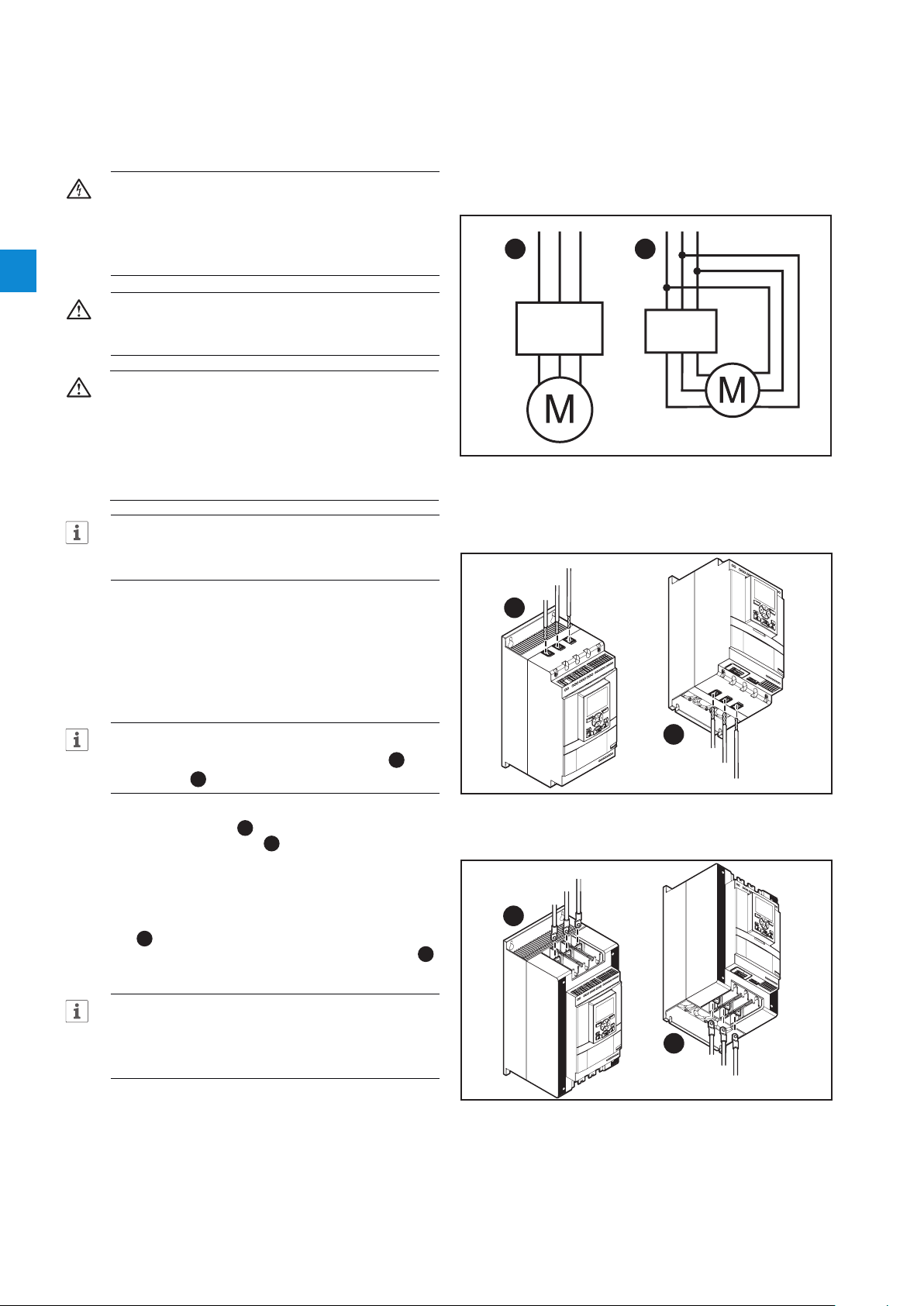
Figure 2.1
In Line (1) and Inside Delta (2) connection
INFORMATION
ABB personnel must obey the instructions in
ABB CISE 15.4.
2.1 Connection
1. To install the Softstarter
see chapter 4 Installation.
INFORMATION
You can connect PSTX Softstarters In Line 1 and
Inside Delta 2, see Figure 2.1.
2. Connect the main circuit: terminals 1L1 - 3L2 5L3 to the line side 1, and terminals 2T1 - 4T2
- 6T3 to the motor side 2, see Figure 2.2.. Use
wire connection for PSTX30...105, see Figure 2.2
and terminal connection for PSTX142...570, see
Figure 2.3.
3. Connect the line side to terminals 1L1, 3L2, 5L3.
see 1 and Figure 2.2. Connect the motor to
terminals 2T1, 4T2, 6T3 on the motor side, see 2
Figure 2.2 and Figure 2.3.
5L3
3L2
1L1
1
Figure 2.2
Terminal connection clamps
1
Line side
5L3
3L2
1L2
Line side
2
Motor side
2T1
4T2
6T3
INFORMATION
Use only wires of the same dimension when you
connect 2 wires to each terminal. (Possible for
PSTX30...105 only).
4. Connect the control supply voltage (100-250V
50/60Hz) to terminal 1 and 2.
5. Connect the functional ground (terminal 22), to a
ground point close to the Softstarter,
see Figure 2.4.
12 Quick start | Installation and commissioning manual | 1SFC132081M0201
Figure 2.3
Terminal connection bars
4T2
Motor side
6T3
2
2T1
Page 13

INFORMATION
1SFC132081M0201
1SFC132081M0201
1SFC132081M0201
1SFC132081M0201
The ground is not a protective ground, it is a
functional ground. The maximum length of the
ground cable is 0.5 m. Connect the ground cable
to the installation plate were the Softstarter is
attached. The installation plate must also be
grounded.
INFORMATION
Do not use functional ground in IT-networks, commonly
found in for instance marine applications.
6. Look at the diagram, see Figure 2.7, and connect
the start/stop circuits: terminal 13, 14, 18, 19 and
20/21, with the internal 24V DC terminal. When
you use internal 24 V DC (terminals 20 or 21), the
terminals 18 and 19 must be connected to each
other. For external control circuit voltage,
see chapter 5.1.2.3 Start and Stop - terminals
13, 14, 18, 19, 20, 21.
WARNING
Use 24V DC only when you connect terminal 13, 14,
15, 16 and 17. Other voltages can cause damage
to the Softstarter and the warranty will no longer be
valid. For more information about terminal 15, 16 and
17, see chapter 5.1.2.4 Programmable inputs -
terminals 15, 16 and 17.
7. Connect terminals 4, 5, 6, 7, 8, 9, 10, 11 and
12 to use the signal output relays. These are
potential-free contacts for maximum 250 V AC, 1.5
A AC-15 and 30 V DC, 5 A DC-12.
See Figure 2.5.
8. Make sure that the operation voltage and control
supply voltage agree with the Softstarter ratings.
9. Set the control supply voltage switch to ON.
10. The green Ready LED is constant lit if the following
conditions are fulfilled:
- Control supply voltage is detected
- Mains three phase voltage is detected
- Mains frequency is within range (40-72Hz)
- Motor connection is detected
- Phase sequence is detected
- No events are active
- Enable signal is active
- If the max nbr of starts per hour function is
enabled and set to stop manual or stop automatic,
the remaining time to start counter (which can be
shown in the HMI homeview) has to be zero
Otherwise the ready LED is flashing, see Figure
2.6.
11. The language settings appear on the screen.
Select your language and push the selection soft
key “OK”. The HMI now downloads the language
data from the Softstarter. This can take some
minutes. When this is done the HMI shows the
Home view.
Figure 2.4
Functional ground, terminal 22
L1
L2
L3
N
KM1
1L13L2 5L3
2T14T2 6T3
UVW
M
3
LN
StartStop
Star 24 V DCt
Stop
Figure 2.7
Circuit diagram (Fuse and contactor version)
L1
L2
L3
N
1L13L2 5L3
2T14T2 6T3
UVW
M
3
LN
StartStop
Star 24 V DCt
Stop
Figure 2.5
Circuit diagram ( MCCB version)
L
N
100-250V
50/60 Hz K4 K4 K4
StartStopResetIn1In2 DGND DND +24V GND
PSTX
22
2014 18 1913
19 201815 16 17141321 21
22
2014 18 1913
19 201815 16 17141321 21 22
2
22
121110987654
22
121110987654
12. Configure applicable parameters as given in
chapter 7 Functions or use the assistants as
given in chapter 2.2 Configuration.
1SFC132081M0201 | Installation and commissioning manual | Quick start 13
Figure 2.6
Flashing “Ready” LED
Page 14

2.2 Configuration
For a quick configuration of the Softstarter, use the
Assistants menu.
The Assistants menus are divided into:
• Basic set-up
- The Basic set-up menu is divided into 4 steps:
1. Language
2. Date and time
3. Motor data
4. System configuration
2
• Application set-up
- The Application set-up is divided into 3 steps:
1. Application set-up
2. Keep/Change values
3. Tune settings
2.2.1 Basic set-up
You see this set-up when you start the Softstarter. To
disable this set-up, see step 6 below.
1. Find the Assistants menu by pushing “Menu”.
Scroll to Assistants with the Navigation keys. Push
“Select” to enter the Assistants menu.
2. Scroll to the Basic set-up menu with the
Navigation keys. Push “Select” to enter the
menu.
3. The Basic set-up starts with step 1 of 5,
Language. Push “Edit” to change language.
Use the Navigation keys to select language and
then push “Save”.
4. Push to enter step 2(5), Date and time. Push
“Edit” and use the Navigation keys to edit date
and time, then push “Save”.
5. Push to enter step 3(5), Motor data.
Push “Edit” to change the Motor rated current
Ie. Use the Navigation keys to change the value
and then push “Save”.
2.2.2 Application set-up
1. Find the Assistants menu from the Home view by
pushing “Menu”. Scroll to Assistants with the
Navigation keys. Push “Select” to enter the
Assistants menu.
2. Scroll to the Application set-up menu with the
Navigation keys and then enter the menu by
pushing “Select”.
3. The Application set-up will start with step 1,
Application type. Scroll to the appropriate
application type and then push “Select”. For
a full Application list, see chapter 7.25 Complete
parameter list.
4. Push to enter step 2, Values. You can select
“Keep actual values” or “Change to recommended
values”. Scroll to the selection of your choice and
Push “Select” to apply.
WARNING!
Note that your saved parameter values are lost if you
select “Change to recommended values”.
5. Push to enter step 3, Tune settings. In most
cases the recommended values are sufficient, but
sometimes fine tuning is necessary. For fine tuning,
push “Edit” and then use the navigation keys
to set:
-Start ramp time: 1 - 120s
-Stop ramp time: 1 - 120s
-Start ramp initial level: 10 - 99%
-Stop ramp end level: 10 - 99%
-Current limit level: 1.5 - 7.5 x Ie
-Start mode: Voltage ramp, Torque ramp or Full
voltage start
-Stop mode: No ramp, Voltage ramp, Torque ramp,
Dynamic brake
6. Push and then push “Done” to finish the
Application set-up. If necessary, fine tuning can
also be done in the Parameters menu.
6. Push to enter step 4(5), System configuration.
Here you can set if the Softstarter enters the Basic
set-up at power on or not. Use the Navigation keys
to select Yes or No and then push “Save”.
7. Push to enter step 5(5) and then Push
“Done” to finish the Basic setup. For more
settings, enter Application set-up.
14 Quick start | Installation and commissioning manual | 1SFC132081M0201
Page 15

2.3 How to start/stop the motor
WARNING
Dangerous voltage: Can cause death or serious
injury. Always set the power switch to off and lock
out all power to this device before you start to
work on the equipment.
WARNING
Approved personnel are allowed to install and
make the electrical connection of the Softstarter
in accordance with existing laws and regulations.
WARNING!
Before you connect the Softstarters PSTX30...
PSTX170 to the operation voltage for the first time,
apply control supply voltage to open the bypass
relays. (see 2.1 Connection). This is necessary to
avoid an accidental start of the equipment while it is
connected to operation voltage.
INFORMATION
ABB personnel must obey the instructions in
ABBCISE15.4.
2
1. Set the operation voltage switch to ON.
2. To start the Softstarter from the keypad, push
the R/L-key to select local control, then push the
Start key on the keypad. Push Stop to stop the
Softstarter
3. To start from hard wire control, push the R/L-key
to select hard wire control, then push the remote
Start key. Push Stop to stop the Softstarter.
1SFC132081M0201 | Installation and commissioning manual | Quick start 15
Page 16

2
16 Quick start | Installation and commissioning manual | 1SFC132081M0201
Page 17

3 Description
3.1 Overview
18
3.1.1 Operation functions 18
3.1.2 Protection functions 18
3.1.2.1 User defined protection 19
3.1.3 Warning functions 19
3.1.4 Fault detection functions 19
3.1.5 Softstarter overview 20
3.1.6 Type designation 21
3.1.7 Environmental influence 21
3.1.8 Specifications 21
3.2 Technical data
22
3.2.1 General 22
3.2.2 Technical data for external keypad 22
3.2.3 Semi-conductor fuses 22
3.2.4 Weights 22
3.2.5 Softstarter ratings 23
3.2.6 Dimensions 25
3
1SFC132081M0201 | Installation and commissioning manual | Description 17
Page 18

This chapter gives a description of the Softstarter in
general, specifications and available components and
spare parts.
3.1 Overview
3.1.1 Operation functions
Available functions are listed below:
• Voltage start ramp
• Voltage stop ramp
• Torque start ramp
The PSTX Softstarter has the latest technology for
soft start and soft stop of squirrel cage motors. The
Softstarter has multiple advanced motor protection
features as standard.
3
WARNING
If using the Rated Operational Voltage U
/N) as source for Control Supply Voltage Us make
sure to not exceed Us 250V AC,50/60Hz.
Bypass
Softstarter range PSTX30...1250 have integrated bypass
components.
User interface
The keypad on the front has Navigation keys, Selection
soft keys, Start and Stop keys, Local or Remote key,
Information key and a clear information screen. You can
select 15 user languages.
You can control the Softstarter in 3 different ways:
• Hardwire inputs control
• Keypad control (either attached to the Softstarter front
or detached and connected with the cable included)
• Fieldbus communication interface (by built in Modbus,
Anybus module or the FieldBus Plug with adapter)
You can use only one type of control at the same time.
Default selection is hardwire inputs control.
(Phase
e
• Torque stop ramp
• Full voltage start
• No ramp
• Stand-still brake
• Current limit
• Kick start
• Slow speed
• Motor heating
• Sequence start
• Automatic restart
3.1.2 Protection functions
The PSTX Softstarter has protection functions to
protect the Softstarter, motor and other equipment. All
protections can have automatic reset or manual reset.
You can enable or disable the protection.
Available protections are listed below:
• EOL protection
• Locked rotor protection
• Phase reversal protection
INFORMATION
Keypad control has the highest priority and
overrides all other control methods.
Fans
The integrated fans for cooling work during ramping
(start/stop) and when the heatsink temperature is too
high. A thermistor monitors the temperature.
• Current imbalance protection
• Overvoltage protection
• Under voltage protection
• Ground fault protection
• Voltage imbalance protection
• Voltage outputs protection
• External thermal sensor - PT100 protection
• External thermal sensor - PTC protection
• Power factor underload protection
• Current underload protection
• User defined protection
• Too long current limit protection
• Bypass open protection
• Fieldbus failure protection
• Extension IO failure protection
• HMI failure protection
• Max number of starts
18 Description | Installation and commissioning manual | 1SFC132081M0201
Page 19

• Frequency range protection
• Phase reversal protection
• Too long start time protection
• Auto restart protection
3.1.2.1 User defined protection
3.1.4 Fault detection functions
The Softstarter has a number of fault detection functions
to signal malfunction at Softstarter, motor or power
network level. The Softstarter identifies external and
internal faults. The user cannot disable fault detection
functions except for Emergency mode, chapter 7.20.1.
You can use your own specified protection, with the
programmable digital input and an external device/sensor.
The protection operates when the input signal comes at
high level (fieldbus or physical I/O).
3.1.3 Warning functions
The Softstarter has warning functions for potential risks,
that operate before a protection function operates.
A warning cannot stop the Softstarter. A reset of a
warning is not necessary.
You can change the warning level and other parameters
for the warning functions. Warnings are stored in the
event list.
Available warnings are listed below:
• Current imbalance warning
• Overvoltage warning
Available faults are listed below:
• Phase loss fault
• High current fault
• Low supply voltage fault
• Bad network fault
• Thyristor overload fault
• Short circuit fault
• Shunt fault
• Unspecified fault
• Heatsink overtemperarure fault
• Open circuit thyristor fault
• Faulty usage
• Connection fault
3
• Under voltage warning
• EOL time-to-trip warning
• EOL warning
• Total Harmonic Distortion (THD) warning
• Voltage imbalance warning
• Power factor underload warning
• Current underload warning
• Fans fault warning
• Locked rotor warning
• Thyristor overload warning
• Short circuit warning
• Number of starts warning
• Modbus configuration warning
• Phase loss warning
• Motor runtime warning
1SFC132081M0201 | Installation and commissioning manual | Description 19
Page 20

3.1.5 Softstarter overview
1SFC132081M0201
Change the settings through Keypad and Fieldbus
communication.
Use the keypad to change settings for each parameter
alone or as a selection of default parameters for different
applications.
Most parameters have one possible setting, but some
parameters have extra settings for sequence start. The
default parameter settings are stored in the unit for a
reset to default.
When the fieldbus communication is selected, most
parameters can also be changed from this interface.
3
Overview, See Figure 3.1.
Terminal marking of
control circuits
Supply voltage Us
L
N
100-250V
50/60 Hz K4 K5 K6
Order code
Ready (Green)
Run (Green)
Ready
Run Fault
Technical data
according to
IEC 60 947-4-2
Technical data
according to UL 508
Com1 Com2
Anybus
connection
(Com1)
Fieldbus plug adapter
connection (Com2)
Motor side connection
Figure 3.1
Softstarter overview
3L21L1 5L3
Start StopIn1 In2DGND+24VGND
4T22T1 6T3
In0
PSTX
Protection
Symbol for
Torque control
Screen
Protection (Yellow)
Fault (Red)
Keypad
Mini USB
Country of origin
Utilization code
Approvals
Terminal marking of
control circuits
Line side connection
20 Description | Installation and commissioning manual | 1SFC132081M0201
Page 21

3.1.6 Type designation
1SFC132081M0201
3.1.8 Specifications
Table 1 Type designation
Designation
(i.e. PSTX370-600-70)
PSTX Softstarter type
370 Current rating
600 Main voltage
70 Supply Voltage
Description
370 = 370A
600 = 208 - 600V 50/60 Hz
690 = 400 - 690V 50/60 Hz
70 = 100 - 250V 50/60 Hz
Type designation, see Figure 3.2.
PSTX-370-600-70
Supply Voltage
70 = 100 - 250V 50/60 Hz
Main voltage
600 = 208 - 600V 50/60 Hz
690 = 400 - 690V 50/60 Hz
Current rating
370 = 370A
Softstarter range
Figure 3.2
Type designation
Table 2 Specifications
General data Description
Degree of protection:
Main circuit
Degree of protection:
Supply and control
circuit
Operating position Vertical at ± 30°
Ambient temperature Storage: -40 °C to +70 °C
Altitude 1000 m (3281 ft.) above sea level without
Pollution degree 3
Relative humidity 5 - 95% (non condensing)
Standards IEC 60529
Standards UL UL508
PTC input IEC 60947-8 Mark A detectors
EMC
Marine approvals Speak to your ABB sales office
PSTX30...105:
IP10
PSTX30...105:
IP20
(-104 °F to 140 °F)
Operation: -25 °C to +60 °C
(-77°F to 104 °F)
De-rating: Above 40 °C (104 F) up to max.
60 °C (140 F) reduce the rated current with
0,8% per °C (0,44% per F).
derating. 1000 - 4000 m (3281 - 13123 ft.)
with derating 0,7%/100 m (0,22%/100ft)
IEC 60947-1
IEC60947-4-2
DIN 44081 and DIN 44082
IEC 60947-4-2 Class A
PSTX142...1250:
IP00
PSTX142...1250:
IP20
1
3
3.1.7 Environmental influence
The product is designed to reduce the effects on the
environment during manufacturing and use of the
product.
Most of the materials used are recyclable. Obey local
laws when you handle and recycle the materials.
You can find further information about used material and
recycling of the product at:
www.abb.com/lowvoltage
The Softstarter is designed for class A equipment.
1
Use of the product in domestic environments can cause
radio interference. If so, it can be necessary to use more
mitigation procedures.
1SFC132081M0201 | Installation and commissioning manual | Description 21
Page 22
3.2 Technical data
3.2.1 General
Table 3 General
General data Description
24 V output 24 V ± 5% Max 250 mA
Rated insulation voltage, Ui600 V / 690 V
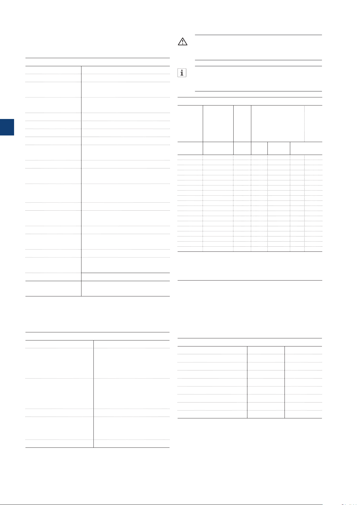
3.2.3 Semi-conductor fuses
WARNING!
Semiconductor fuses must be used to keep the
warranty on the thyristors.
INFORMATION
To achieve a type 2 coordination, semiconductor
fuses must be used.
Rated operation voltage, Ue208-600 / 690 V, 50 / 60 Hz
Rated supply voltage,Us 100-250 V, 50 / 60 Hz
3
Voltage tolerance +10% to -15%
Rated frequency 50 / 60 Hz
Frequency tolerances ± 10%
Rated impulse withstand
voltage
6 kV Operation circuit
4 kV Control and supply circuit
Relay outputs 3 programmable
Number of controlled
3
phases
Inputs Start, stop, 3 programmable inputs
(Digital I/O: In0, In1, In2), temperature
sensor input.
Outputs Relay outputs: K4 K5 K6.
Output relay
250 V AC, Ith = 5A, Ie = 1.5A (AC-15)
performance
Analog output 4-20 mA, 0-20 mA, 0-10 V, 0-10 mA
PTC input 2825 ohm ± 20% switch off resistance
1200 ohm ± 20% switch on resistance
Cooling system Fan
Recommended fuse
Control supply circuit
6 A Delayed
MCB use C characteristics
Communication 3 Fieldbus ports, Extension I/O
Communication
protocols
DeviceNet / Profibus DP / Modbus /
EtherNET/IP / Modbus TCP/ Profinet
Table 5 Fuses ratings and power losses
Current
range
Max
Max fuse raiting - main
1) 2)
circuit
power
Bussmann fuses, DIN43 620
loss at
(Knife)
rated I
e
Power
require-
ments
supply
circuit
Holding
(VA) /
Type A W A Type Size
Pull-in
(VA)
PSTX30 9.0...30.0 0.8 100 170M1567 000 49/51
PSTX37 11.1...37.0 1.2 125 170M1568 000 49/51
PSTX45 13.5...45.0 1.8 160 170M1569 000 49/51
PSTX60 18.0...60.0 3.2 160 170M1569 000 49/51
PSTX72 21.6...72.0 4.7 250 170M1571 000 49/51
PSTX85 22.5...85.0 6.5 315 170M1572 000 49/51
PSTX105 31.8...106.0 10 400 170M3819 1* 49/51
PSTX142 42.9...143.0 18 500 170M5810 2 49/53
PSTX170 51.3...171.0 26 630 170M5812 2 49/53
PSTX210 63.0...210.0 48 630 170M5812 2 56/276
PSTX250 75.0...250.0 68 700 170M5813 2 56/276
PSTX300 90.0...300.0 97 800 170M6812 3 56/276
PSTX370 111.0...370.0 148 900 170M6813 3 56/276
PSTX470 141.0...470.0 99 900 170M6813 3 67/434
PSTX570 171.0...570.0 146 1000 170M6814 3 67/434
PSTX720 216.0...720.0 78 1250 170M8554 3 61/929
PSTX840 252.0...840.0 106 1500 170M6018 3 61/929
PSTX1050 3)315.0...1050.0 165 1800 170M6020 3 68/929
PSTX1250
3) 4)
1)
For the supply circuit 6 A delayed, for MCB use C characteristics.
2)
For inside delta connection the fuses shall be placed inside the delta. Contact ABB for
more information.
3)
170M6019 with fuse rating 1600 A should be used for 690 V version.
4)
For 690 V version, Bussmann fuses are only available for motors with rated current up
to 1150 A.
375.0...1250.0 234 2000 170M6021 3 68/929
You can find more detailed information at:
http://applications.it.abb.com/SOC/
3.2.2 Technical data for external keypad
3.2.4 Weights
Table 4 Technical data for external keypad
Display Display type
Status indicating LEDs Ready: Green
Run: Green
Protection: Yellow
Fault: Red
Ambient temperature Storage: -25 °C to +70 °C (-13 °F
to 158 °F)
Operation: -25 °C to +60 °C
(-13 °F to 140 °F)
Degree of protection IP66
Table 6 Weights
Type Weight in kg Weight in lbs
PSTX30...105 6,1 13,5
PSTX142...170 9,6 21,2
PSTX210...370 12,7 27,9
PSTX470 25.5 55.1
PSTX570 27.5 59.5
PSTX720 ...840 46.2 101.4
PSTX1050 64.5 141.1
PSTX1250 65 143.3
UL approval Type 1
Type 4X
Type 12
Marine approvals Speak to your ABB sales office
22 Description | Installation and commissioning manual | 1SFC132081M0201
Page 23

3.2.5 Softstarter ratings
PSTX30…1250 Temp ≤ + 40
IEC
Softstarter type Order number Ie range
PSTX30-600-70 1SFA898103R7000 9-30A 7,5 15 18,5 12,5 25 30 30 52
PSTX30-690-70 1SFA898203R7000 9-30A 15 18,5 25 25 30 45 30 52
PSTX37-600-70 1SFA898104R7000 11,1-37A 9 18,5 22 15 30 37 37 64
PSTX37-690-70 1SFA898204R7000 11,1-37A 18,5 22 30 30 37 55 37 64
PSTX45-600-70 1SFA898105R7000 13,5-45A 12,5 22 25 25 37 45 45 76
PSTX45-690-70 1SFA898205R7000 13,5-45A 22 25 37 37 45 59 45 76
PSTX60-600-70 1SFA898106R7000 18-60A 15 30 37 30 55 75 60 105
PSTX60-690-70 1SFA898206R7000 18-60A 30 37 55 55 75 90 60 105
PSTX30...105
PSTX72-600-70 1SFA898107R7000 21,6-72A 18,5 37 45 37 59 80 72 124
PSTX72-690-70 1SFA898207R7000 21,6-72A 37 45 59 59 80 110 72 124
PSTX85-600-70 1SFA898108R7000 25,5-85A 22 45 55 40 75 90 85 147
PSTX85-690-70 1SFA898208R7000 25,5-85A 45 55 75 75 90 132 85 147
PSTX105-600-70 1SFA898109R7000 31,8-106A 30 55 75 55 90 110 106 181
PSTX105-690-70 1SFA898209R7000 31,8-106A 55 75 90 90 110 160 106 181
PSTX142-600-70 1SFA898110R7000 42,9-143A 37 75 90 75 132 160 143 245
PSTX142-690-70 1SFA898210R7000 42,9-143A 75 90 132 132 160 220 143 245
PSTX170-600-70 1SFA898111R7000 51,3-171A 45 90 110 90 160 200 171 300
PSTX170-690-70 1SFA898211R7000 51,3-171A 90 110 160 160 200 257 171 300
PSTX142-170
PSTX210-600-70 1SFA898112R7000 63-210A 59 110 132 102 184 250 210 360
PSTX210-690-70 1SFA898212R7000 63-210A 110 132 184 184 250 315 210 360
PSTX250-600-70 1SFA898113R7000 75-250A 75 132 160 132 220 295 250 430
PSTX250-690-70 1SFA898213R7000 75-250A 132 160 220 220 295 400 250 430
PSTX300-600-70 1SFA898114R7000 90-300A 90 160 200 160 257 355 300 515
PSTX300-690-70 1SFA898214R7000 90-300A 160 200 257 257 355 500 300 515
PSTX210...370
PSTX370-600-70 1SFA898115R7000 111-370A 110 200 257 200 355 450 370 640
PSTX370-690-70 1SFA898215R7000 111-370A 200 257 355 355 450 600 370 640
PSTX470-600-70 1SFA898116R7000 141-470A 132 250 315 250 450 600 470 814
PSTX470-690-70 1SFA898216R7000 141-470A 250 315 450 450 600 800 470 814
PSTX570-600-70 1SFA898117R7000 171-570A 160 315 400 295 540 700 570 987
PSTX470...570
PSTX570-690-70 1SFA898217R7000 171-570A 315 400 560 540 700 960 570 987
PSTX720-600-70 1SFA898118R7000 216-720A 200 400 500 355 710 880 720 1247
PSTX720-690-70 1SFA898218R7000 216-720A 400 500 710 710 880 1200 720 1247
PSTX840-600-70 1SFA898119R7000 252-840A 250 450 600 450 800 1000 840 1455
PSTX720...840
PSTX840-690-70 1SFA898219R7000 252-840A 450 600 800 800 1000 1400 840 1455
PSTX1050-600-70 1SFA898120R7000 315-1050A 315 560 730 500 1000 1250 1050 1810
PSTX1050-690-70 1SFA898220R7000 315-1050A 560 730 1000 1000 1250 1700 1050 1810
PSTX1250-600-70 1SFA898121R7000 375-1250A 400 710 880 670 1200 1500 1250 2160
PSTX1050...1250
PSTX1250-690-70 1SFA898221R7000 375-1250A 710 880 1200 1200 1500 2000 1250 2160
when connected In Line
220-
380-
230V
400V 500V 690V
kW kW kW kW kW kW kW kW A A
°
Motor power
C (104 °F), 4 * Ie in 10 sec.
when connected Inside Delta
220230V
Motor power
380-
400V 500V 690V In Line
Rated current
Ie
Inside
Delta
3
1) All data for 40°C ambient. Above 40°C (104 F) up to max.
40°C (140 F) reduce the rated current with 0,8% per 40°C
(0,44% per F).
1SFC132081M0201 | Installation and commissioning manual | Description 23
Page 24

PSTX30…1250 Temp ≤ + 40
°
C (104 °F), 4 * Ie in 10 sec.
Softstarter type Order number
Motor power
when connected In Line
220240V
440480V
208V
hp hp hp hp hp hp hp hp A A
550600V 208V
Motor power
when connected Inside Delta
220-
440-
240V
480V
Rated current
550-
600V In Line
Ie
Inside
Delta
PSTX30-600-70 1SFA898103R7000 7,5 10 20 25 10 15 30 40 28 48
PSTX30-690-70 1SFA898203R7000 20 25 30 40 28 48
PSTX37-600-70 1SFA898104R7000 10 10 25 30 15 20 40 50 34 58
PSTX37-690-70 1SFA898204R7000 25 30 40 50 34 58
PSTX45-600-70 1SFA898105R7000 10 15 30 40 20 25 50 60 42 72
PSTX45-690-70 1SFA898205R7000 30 40 50 60 42 72
PSTX60-600-70 1SFA898106R7000 20 20 40 50 30 40 75 100 60 103
PSTX60-690-70 1SFA898206R7000 40 50 75 100 60 103
PSTX30...105
PSTX72-600-70 1SFA898107R7000 20 25 50 60 30 40 75 100 68 117
3
PSTX72-690-70 1SFA898207R7000 50 60 75 100 68 117
PSTX85-600-70 1SFA898108R7000 25 30 60 75 40 50 100 125 80 138
PSTX85-690-70 1SFA898208R7000 60 75 100 125 80 138
PSTX105-600-70 1SFA898109R7000 30 40 75 100 60 60 150 150 104 180
PSTX105-690-70 1SFA898209R7000 75 100 150 150 104 180
PSTX142-600-70 1SFA898110R7000 40 50 100 125 75 75 150 200 130 225
PSTX142-690-70 1SFA898210R7000 100 125 150 200 130 225
PSTX170-600-70 1SFA898111R7000 50 60 125 150 75 100 200 250 169 292
PSTX170-690-70 1SFA898211R7000 125 150 200 250 169 292
PSTX142-170
PSTX210-600-70 1SFA898112R7000 60 75 150 200 100 125 250 300 192 332
PSTX210-690-70 1SFA898212R7000 150 200 250 300 192 332
PSTX250-600-70 1SFA898113R7000 75 100 200 250 150 150 350 450 248 429
PSTX250-690-70 1SFA898213R7000 200 250 350 450 248 429
PSTX300-600-70 1SFA898114R7000 100 100 250 300 150 200 450 500 302 523
PSTX300-690-70 1SFA898214R7000 250 300 450 500 302 523
PSTX210...370
PSTX370-600-70 1SFA898115R7000 125 150 300 350 200 250 500 600 361 625
PSTX370-690-70 1SFA898215R7000 300 350 500 600 361 625
PSTX470-600-70 1SFA898116R7000 150 200 400 500 250 300 600 700 480 830
PSTX470-690-70 1SFA898216R7000 400 500 600 700 480 830
PSTX570-600-70 1SFA898117R7000 200 200 500 600 300 350 700 800 590 1020
PSTX570-690-70 1SFA898217R7000 500 600 700 800 590 1020
PSTX470...570
PSTX720-600-70 1SFA898118R7000 250 300 600 700 400 500 1000 1200 720 1240
PSTX720-690-70 1SFA898218R7000 600 700 1000 1200 720 1240
PSTX840-600-70 1SFA898119R7000 300 350 700 800 500 600 1200 1500 840 1450
PSTX840-690-70 1SFA898219R7000 700 800 1200 1500 840 1450
PSTX720...840
PSTX1050-600-70 1SFA898120R7000 400 450 900 1000 600 700 1500 1900 1062 1830
PSTX1050-690-70 1SFA898220R7000 900 1000 1500 1900 1062 1830
PSTX1250-600-70 1SFA898121R7000 400 500 1000 1200 800 900 1800 2000 1250 2160
PSTX1250-690-70 1SFA898221R7000 1000 1200 1800 2000 1250 2160
PSTX1050...1250
4 * Ie in 10 sec
Ordering data according to UL (40°C ambient)
24 Description | Installation and commissioning manual | 1SFC132081M0201
Page 25
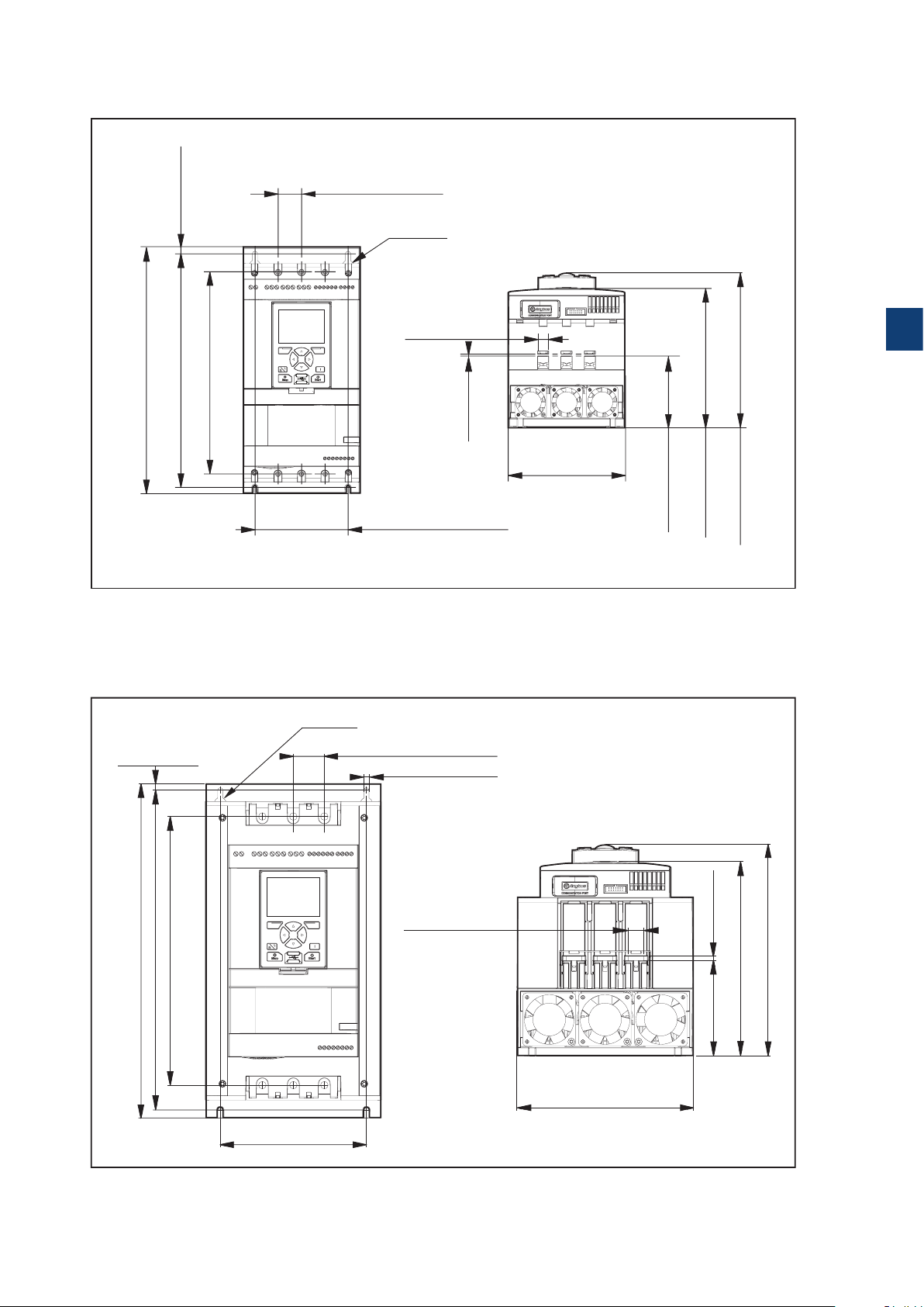
3.2.6 Dimensions
197.5 mm (7,7 in)
90,5 mm (3,6 in
178.8 mm (7 in)
1SFC132081M0201
1SFC132081M0201
PSTX30...105
30 mm (1,2 in) 4x
Ø14 (2x)
314 mm (12,4 in)
298,5 mm (11,7 in) 7,5 mm (0,3 in)
258 mm (10,2 in)
Figure 3.3
Dimensions PSTX30...105
PSTX142...170
7,5 mm (0,3 in)
Ø18 (2x)
13 mm (0,5 in) 6x
119 mm (4,7 in)
35 mm (1,3 in) 4x
6.6 mm (0,2 in) 4x
3
3 mm (0,1 in)
)
150 mm (5,9 in)
377 mm (14,8 in)
303 mm (11,9 in)
360,5 mm (14,1 in)
Figure 3.4
Dimensions PSTX142...170
165 mm (6,5 in)
17,5 mm (0,7 in) 6x
199 mm (7,8 in)
1SFC132081M0201 | Installation and commissioning manual | Description 25
5 mm (0,2 in)
219,6 mm (8,6 in)
107,6 mm (4,2 in)
238,3 mm (9,3 in)
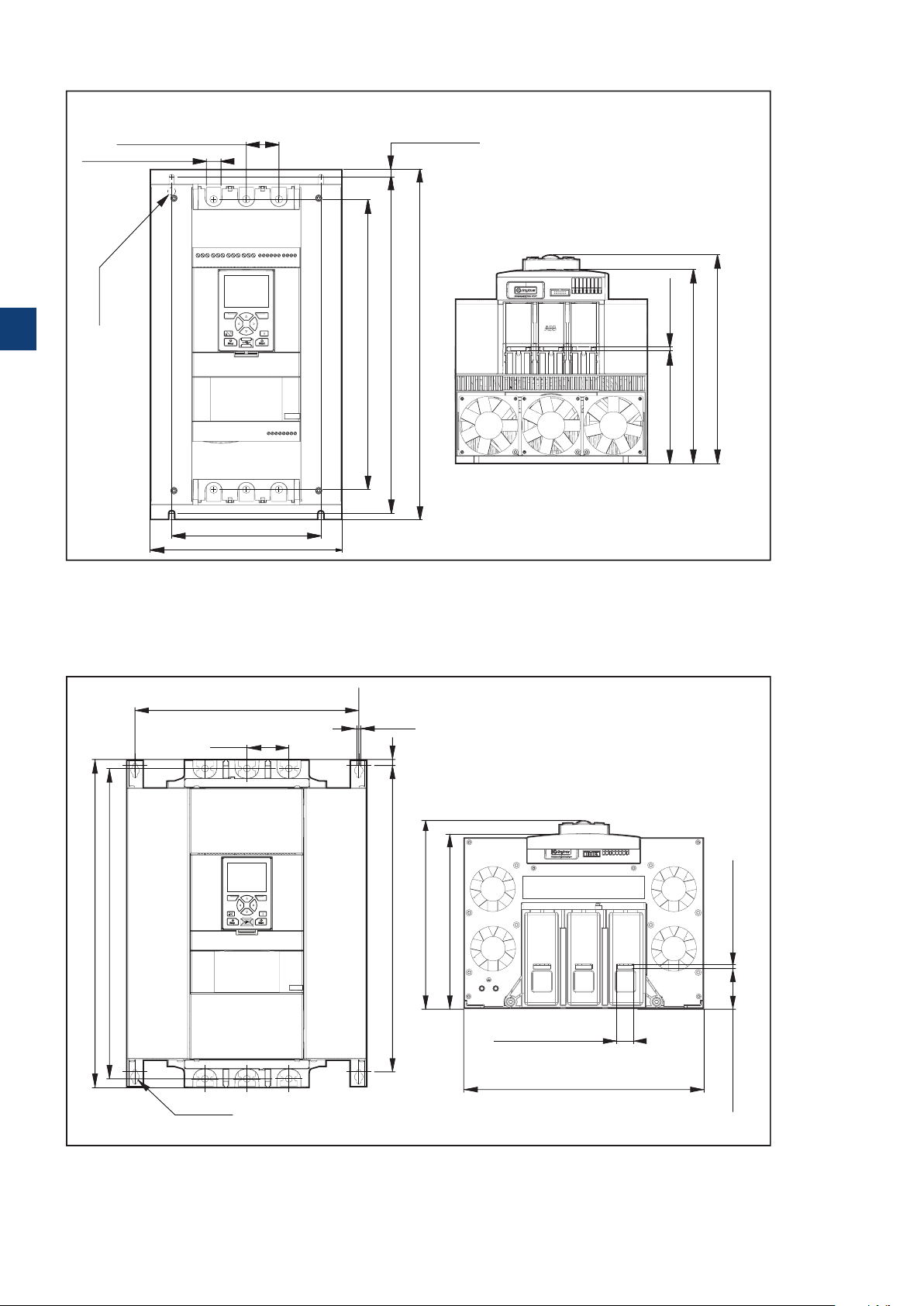
Page 26
1SFC132081M0201
1SFC132081M0201
58.2 mm (2.3 in) 6x
PSTX210...370
43,7 mm (1,7 in) 4x
19,6 mm (0,8 in) 6x
10,5 mm (0,4 in)
Ø18 (2x)
3
389 mm (15,3 in)
470 mm (18,5 in)
451.2 mm (17,7 in)
5 mm (0,2 in)151 mm (5,9 in)
Figure 3.5
Dimensions PSTX210..370
PSTX470...570
336 mm (13.2 in) 2x
63 mm (2.5 in) 4x
493 mm (19.4 in)
466 mm (18.3 in)
Ø13 (4x)
Figure 3.6
Dimensions PSTX470..570
200 mm (7,9 in)
258 mm (10,2 in)
7 mm (0.2 in) 4x
9 mm (0.3 in)
460 mm (18.1 in)
262.82 mm (10.3 in)
282.15 mm (11.1 in)
260 mm (10,2 in)
279.1 mm (10,9 in)
6 mm (0.2 in) 6x
25 mm (0.9 in) 6x
361 mm (14.2 in)
26 Description | Installation and commissioning manual | 1SFC132081M0201
Page 27
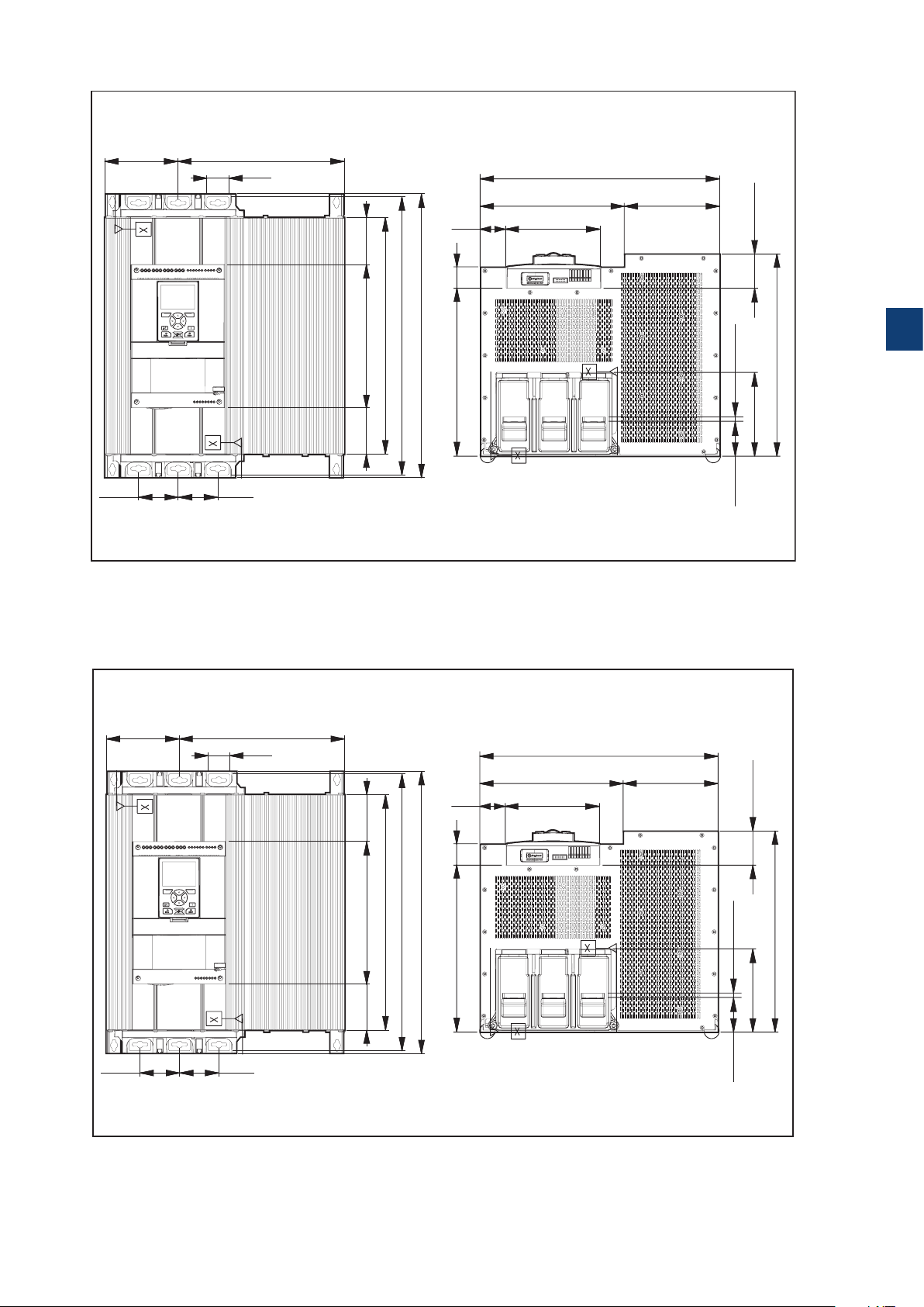
62.6 (6x) mm (in)
62.6 (6x) mm (in)
PSTX720...PSTX840
133.5(2x) mm
(5.2 in)
72(2x) mm
(2.8 in)
72(2x) mm
(2.8 in)
Figure 3.7
Dimensions PSTX720..840
PSTX1050
301.5 mm (11.8 in)
40 (6x) mm
(1.5 in)
(3.37 in)
505 mm (19.8 in)
430 mm (16.9 in)
260 mm (10.2 in) 85.6 mm
(3.3 in)
84.4 mm
46.5 mm
(1.8 in)
39 mm
(1.5 in)
515 mm (20.2 in)
304.5 mm (11.9 in)
435 mm (17.1 in)
172 mm (6.7 in)
173.4 mm (6.8 in)261.6 mm (10.2 in)
62 mm (2.4 in)
3
(0.3 in)
8 (6x) mm
366.5 mm (14.4 in)
152 (2x) mm (5.9 in)
133.5(2x) mm
(5.2 in)
72(2x) mm
(2.8 in)
Figure 3.8
Dimensions PSTX1050
72(2x) mm
(2.8 in)
301.5 mm (11.8 in)
40 (6x) mm
(1.5 in)
(3.37 in)
505 mm (19.8 in)
430 mm (16.9 in)
260 mm (10.2 in) 85.6 mm
(3.3 in)
84.4 mm
46.5 mm
(1.8 in)
39 mm
(1.5 in)
515 mm (20.2 in)
304.5 mm (11.9 in)
435 mm (17.1 in)
172 mm (6.7 in)
173.4 mm (6.8 in)261.6 mm (10.2 in)
62 mm (2.4 in)
(0.3 in)
8 (6x) mm
366.5 mm (14.4 in)
152 (2x) mm (5.9 in)
1SFC132081M0201 | Installation and commissioning manual | Description 27
Page 28
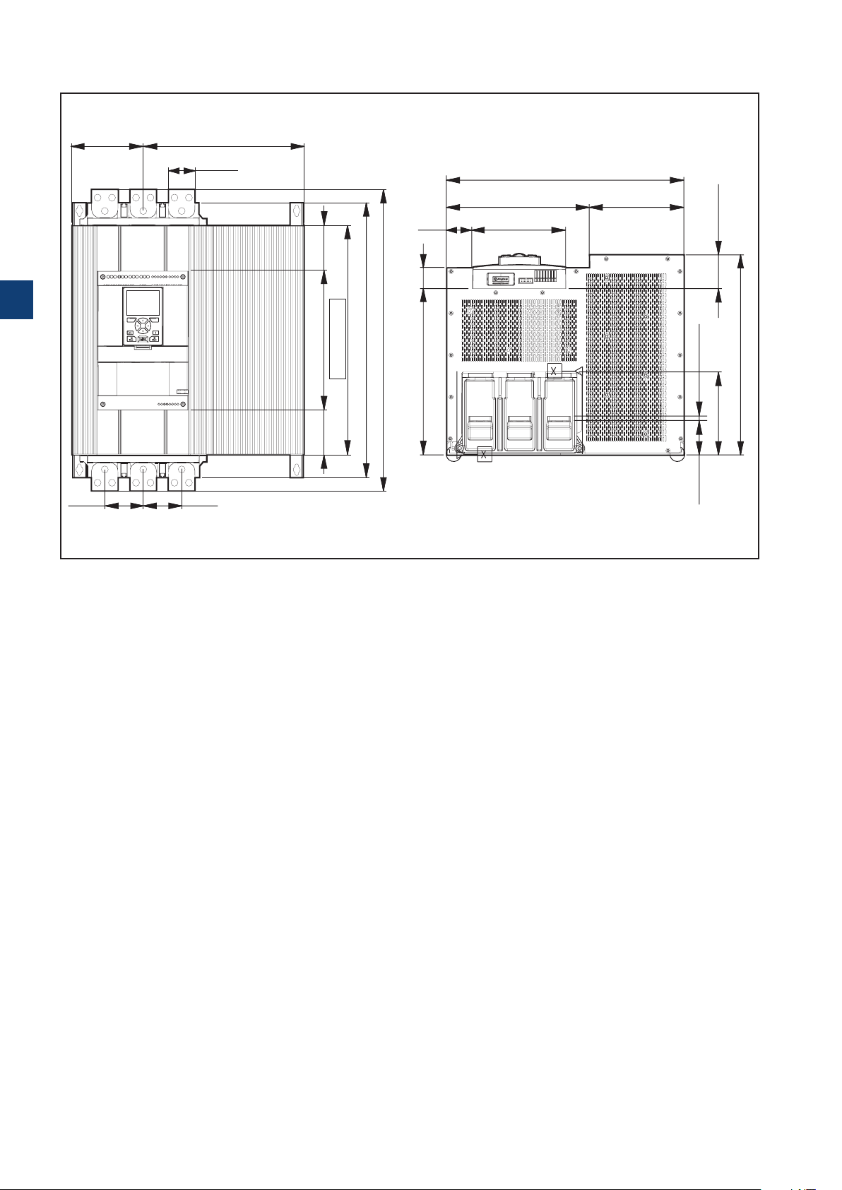
62.6 (6x) mm (in)
PSTX1250
133.5(2x) mm
(5.2 in)
3
301.5 mm (11.8 in)
50 (6x) mm
(1.9 in)
(3.32 in)
84.35 mm
46.5 mm
(1.8 in)
39 mm
(1.5 in)
435 mm (17.1 in)
173.4 mm (6.8 in)261.6 mm (10.2 in)
172 mm (6.7 in)
62 mm (2.4 in)
515 mm (20.2 in)
565 mm (22.2 in)
430 mm (16.9 in)
261.3 mm (10.2 in)
304.5 mm (11.9 in)
(3.32 in)
84.35 mm
(0.3 in)
8 (6x) mm
152 (2x) mm (5.9 in)
366.5 mm (14.4 in)
72(2x) mm
(2.8 in)
72(2x) mm
(2.8 in)
Figure 3.9
Dimensions PSTX1250
28 Description | Installation and commissioning manual | 1SFC132081M0201
Page 29

3
1SFC132081M0201 | Installation and commissioning manual | Description 29
Page 30

3
30 Description | Installation and commissioning manual | 1SFC132081M0201
Page 31

4 Installation
4.1 Receive, unpack and examine
32
4.2 Install
33
4.2.1 Lifting the Softstarter 33
4.2.2 Minimum distance to wall/front 33
4.2.3 Minimum enclosure dimensions 34
4.2.4 Maximum installation angle 34
4.2.5 Dimensions and drilling plan 34
4.2.6 Movable keypad 34
4.2.6.1 Installation Movable HMI 35
4
1SFC132081M0201 | Installation and commissioning manual | Installation 31
Page 32

This chapter contains instructions to receive and install
1SFC132081M0201
the Softstarter.
WARNING
If you do not obey these instructions, it can cause the
Softstarter to overheat or not operate correctly.
4.1 Receive, unpack and examine
WARNING
Risk of damage to property. Make sure that no
liquids, dust or conductive parts can go into the
Softstarter.
4
Make sure that the package is placed with the correct
side up, see Figure 4.1.
• Remove the transport casing.
• Make sure that the order code agrees with the delivery
documents.
• Make sure that all items are included, see the delivery
note. See Table 1 Delivery note.
• Examine the Softstarter and the packaging. In case of
damages, speak to the transport company or the ABB
reseller/Office immediately.
• Keep the Softstarter in its packaging until installation.
Table 1 Delivery note
Softstarter type Items included with the Softstarter
PSTX30...105
PSTX142...170
• 1SFB262001D1000 – HMI Mounting Kit
• 1SFC132082M9901 – PSTX Short Form Manual
• 1SFB262001D1000 – HMI Mounting Kit
• 1SFC132082M9901 – PSTX Short Form Manual
• 1SFA899221R1002 – Terminal Kit # PSLE-185
Figure 4.1
Receiving, unpacking and checking
PSTX210...370
PSTX470...570
PSTX720...840
PSTX1050...1250
32 Installation | Installation and commissioning manual | 1SFC132081M0201
• 1SFB262001D1000 – HMI Mounting Kit
• 1SFC132082M9901 – PSTX Short Form Manual
• 1SFA899221R1003 – Terminal Kit # PSLE-300
• 1SFB262001D1000 – HMI Mounting Kit
• 1SFC132082M9901 – PSTX Short Form Manua
• 1SFA899221R1004 - Terminal Kit # PSLE-460l
• 2191323-A - Mounting kit
• 11SFB262001D1000 – HMI Mounting Kit
• 1SFC132082M9901 – PSTX Short Form Manual
• 1SFA899221R1005 - Terminal Kit#PSLE-750
• 2191323-A - Mounting kit
• 11SFB262001D1000 – HMI Mounting Kit
• 1SFC132082M9901 – PSTX Short Form Manual
• 1SFA899221R1005 - Terminal Kit#PSLE-750
• 2191323-A - Mounting kit
Page 33

4.2 Install
1SFC132081M0201
1SFC132081M0201
C
1SFC132081M0201
The Softstarters are available in different physical sizes
and all of them should be mounted with M6 bolts, or bolts
with the same dimension and strength.
4.2.1 Lifting the Softstarter
Use lifting equipment to install the models
PSTX470...1250. See chapter 3.2.4 Weights, for weights.
You can install the PSTX30...370 without lifting equipment
4.2.2 Minimum distance to wall/front
4
WARNING
Risk of damage to property. Make sure that
no liquids, dust or conductive parts enter the
Softstarter.
WARNING
If you do not obey these instructions, this can cause
the Softstarter to overheat or not operate correctly.
For sufficient cooling, install the Softstarter vertically.
Prefect blockage of the airways, see Figure 4.2.
INFORMATION
Make sure that the distances to the surrounding
walls are sufficient. For the minimum distance to
front and wall, see Figure 4.3 , Figure 4.4 and
Table 2.
Table 2 Minimum distance to wall/front
Softstarter type
PSTX30...105 100 10 35 3.94 0.39 1.38
PSTX142...170 100 10 35 3.94 0.39 1.38
PSTX210...370 100 10 35 3.94 0.39 1.38
PSTX470...570 150 15 35 5.905 0.590 1.38
PSTX720...840 150 15 35 5.905 0.590 1.38
PSTX1050...1250 150 15 35 5.905 0.590 1.38
A
(mm)B (mm)C (mm)
A
(in)B(in)C(in)
Figure 4.2
Flow of air for cooling purpose
Figure 4.3
Minimum distances to wall
A
A
BB
Figure 4.4
Minimum distances to front
1SFC132081M0201 | Installation and commissioning manual | Installation 33
Page 34

4.2.3 Minimum enclosure dimensions
1SFC132081M0201
1SFC132081M0201
1SFC132081M0201
1SFC132081M0201
In applications where the Softstarter is installed in an
enclosure, use these minimum enclosure dimensions. See
Figure 4.5 and Table 3 and 4.
Table 3 Minimum enclosure dimensions (IEC)
IEC
Softstarter type W (mm) H (mm) D (mm)
PSTX30...105 508 508 305
PSTX142...170 508 508 305
PSTX210...370 762 914 305
PSTX470...570 914 1219 405
PSTX720...840 914 1524 405
PSTX1050...1250* 914 1524 405
*PSTX1250 Recommended fan capacity 230m3/h
4
Table 4 Minimum enclosure dimensions (UL)
Softstarter type W (in) H (in) D (in) Min number of
PSTX30...105 20 20 10 2
PSTX142...170 20 20 12 2
PSTX210...370 30 24 12 7
PSTX470...570 36 48 16 8
PSTX720...840 36 60 16 8
PSTX1050...1250* 36 60 16 8
*PSTX1250 Recommended fan capacity 230m3/h
Minimum enclosure dimensions
D
Figure 4.5
Minimum enclosure size
Minimum enclosure dimensions
latches
Figure 4.6
Airflow
H
W
4.2.4 Maximum installation angle
Make sure that the distances to the walls are
sufficient. Use the installation angle given in
Figure.
4.2.5 Dimensions and drilling plan
For dimensions and drilling plan see chapter 3.2.6
Dimensions. Drilling plan is also printed on the box.
WARNING
Risk of damage to property. Ensure that no
liquids, drilling particles, dust or conductive parts
enter the Softstarter.
WARNING
When the enclosure is too small and/or you do
not obey the instructions, the Softstarter can
overheat or not operate correct.
4.2.6 Movable keypad
O
30
Figure 4.7
Maximum mounting angle
30
O
30
O
30
O
2
If you remove the PSTX keypad, connect it with the
included 3 meter cable for serial communication and
power supply. Connect the cable to the network port on
the front of the Softstarter. To remove the keypad, push
the lock with a screwdriver, see 1 and 2 in Figure 4.8.
34 Installation | Installation and commissioning manual | 1SFC132081M0201
Figure 4.8
Detach the keypad
1
Page 35

4.2.6.1 Installation Movable HMI
1SFC132081M0201
1SFC132081M0201
1SFC132081M0201
1SFC132081M0201
INFORMATION
Do not use shielded RJ45 cables. Use a cable
length of maximum 3m to reduce distortion of the
communication.
INFORMATION
The Softstarter HMI is IP66 approved when
installed on the enclosure door.
You can use the movable HMI to copy parameters
from one Softstarter to another during commissioning
(temporarily handheld).
Included with the Softstarter comes:
1
2 Nm (17,7 lb.in)
Figure 4.9
Drill a hole for the detachable keypad
Min. Ø25,5 (Ø 1,0”)
Max. Ø28 (Ø 1,1”)
3
2
(Ø 1.02”)Ø26
• Rubber gasket
• Plastic screw-nut
• RJ45 Network cable
1. To remove the movable HMI from the Softstarter,
loosen the plastic latch below the movable HMI,
see 1 and 2 in Figure 4.9.
2. Drill a hole where to attach the movable HMI.
Maximum dimension of the hole is Ø26 (Ø 1.02”),
see 1 in Figure 4.9. Put the rubber packing
around the threaded network connector on the
movable HMI, see 2 in Figure 4.9. Push the
threaded network connector through the drilled
hole.
See 3 in Figure 4.9. Fasten the plastic screw-nut
on the threaded network connector, with 2 Nm
(17.7 lb/in).
3. Remove the RJ45 plug see 4. Connect one end of
the network cable to the network port on the front
of the Softstarter 5 in Figure 4.10.
Figure 4.10
Connect one end of the network cable
6
5
4
4
4. Connect the other end of the network cable to the
network port on the back of the movable HMI, see
6
in Figure 4.11.
5. Make sure that the network cable is properly
inserted into the 2 ports. Prevent the rest of the
cable to get caught between the door, see 7 in
Figure 4.12. Close the door of the enclosure and
set the operation voltage switch to ON. Make sure
that the external HMI works.
1SFC132081M0201 | Installation and commissioning manual | Installation 35
Figure 4.11
Connect the other end of the network cable
7
Figure 4.12
Roll the rest of the hanging cable
Page 36

4
36 Installation | Installation and commissioning manual | 1SFC132081M0201
Page 37

5 Connection
5.1 Electrical connection
38
5.1.1 Main circuit 38
5.1.1. 2 Tightening torques and cable dimensions 39
5.1.1.3 Softstarter connections 39
5.1.2 Control supply and control circuit 40
5.1.2.1 Control supply voltage - terminals1and2 40
5.1.2.2 Functional ground - terminal 22 40
5.1.2.3 Start and Stop - terminals 13, 14, 18, 19, 20, 21 41
5.1.2.4 Programmable inputs - terminals 15, 16 and 17 43
5.1.2.5 Programmable inputs (Sequence start) 44
5.1.2.6 Programmable output relay - K4, terminals 4, 5 and 6 45
5.1.2.7 Programmable output relay - K5, terminals 7, 8 and 9 45
5.1.2.8 Programmable output relay - K6, terminals 10, 11 and 12 45
5.1.2.9 Close bypass PSTX470...PSTX1250 46
5.1.2.10 Modbus RTU 46
5.1.2.11 PTC / PT10 0 i n p ut 46
5.1.2.12 Analog output 49
5.1.3 Extension I/O 49
5
1SFC132081M0201 | Installation and commissioning manual | Connection 37
Page 38

This chapter gives a description of the electrical
1SFC132081M0201
1SFC132081M0201
1SFC132081M0201
connections and connections for communication devices.
WARNING
Installation of electrical connections must be
done by authorized personnel. Obey all laws and
regulations.
WARNING
Dangerous voltage. Can cause death or serious
injury. Always set the power switch to off and lock
out all power to this device before you start to
work on the equipment.
WARNING!
Before you connect the Softstarters PSTX30...
PSTX170 to the operation voltage for the first time,
apply control supply voltage to open the bypass
relays. (see 2.1 Connection). This is necessary to
avoid an accidental start of the equipment while it is
connected to operation voltage.
1 2
PSTX
Figure 5.1
In line (1) and inside delta (2) connection
PSTX
5
ABB personnel must obey the instructions in
ABBCISE15.4.
For basic connection, see chapter 2 Quick start.
For wiring diagrams, see chapter 11 Wiring and
application diagrams.
5.1 Electrical connection
WARNING
Capacitors for power factor compensation are
not permitted in between the Softstarter and the
motor, because this can cause current peaks
which can burn the thyristors in the Softstarter. If
you must use such capacitors, connect them on
the line side of the Softstarter.
Figure 5.2
Clamp connection
5L3
3L2
1L1
1
1
1L2
3L2
Line side
5L3
Line side
Motor side
2
2T1
4T2
6T3
5.1.1 Main circuit
INFORMATION
The maximum allowed voltage dip between
Softstarter and motor is 5% despite the different
INFORMATION
cable length. The load must be inductive or
resistive. The softstarter can’t start a capacitive
load.
Softstarters PSTX30...PSTX1250 can be connected InLine,
see 1 Figure 5.1, and Inside Delta, see 2 Figure 5.1.
Use wire connection for PSTX30...105 see Figure 5.2
Terminal connection for PSTX142...1250 see Figure 5.3.
• Connect the line side to terminals 1L1, 3L2, 5L3, see
1
in Figure 5.2 and Figure 5.3.
• Connect the motor to terminals 2T1, 4T2, 6T3 on the
motor side, see 2 in Figure 5.2 and Figure 5.3.
Figure 5.3
Terminal connection bar
2
2T1
4T2
Motor side
6T3
The terminal marking is printed on the front of the
Softstarter. For tightening torques and cable thickness,
see chapter 5.1.1.2 Tightening torques and cable
dimensions.
38 Connection | Installation and commissioning manual | 1SFC132081M0201
Page 39

1SFC132081M0201
5.1.1.2 Tightening torques and cable dimensions
PSTX30...105
1L1
3L2 5L3
2T1 4T2 6T3
PSTX142...170
1L1
3L2 5L3
2T1 4T2 6T3
PSTX210...370
1L1 3L2 5L3
2T1 4T2 6T3
PSTX470...570
1L1 3L2 5L3
2T1 4T2 6T3
PSTX720...840
1L1 3L2 5L3
2T1 4T2 6T3
PSTX1050...1250
1L1 3L2 5L3
2T1 4T2 6T3
M8
8 Nm - 71 Ib.in
11/6-16 UNF-2
275 lb.in
3/4-16 UNF-2A
375 lb.in
5/8-18 UNF-2A
275 lb.in
3/4-16 UNF-2A
375 lb.in
5/8-18 UNF-2A
275 lb.in
3/4-16 UNF-2A
375 lb.in
M12
45 Nm - 398 lb.in
AWG6 .. 2/0
Cu 75°C only
Rigid: 10 ... 95 mm²
Flexible: 10 ... 70 mm²
Rigid/flexible: 2x6 ... 2x35 mm²
Using connection module
A
ATK185: AWG4 to 300kcmil
AI Cu 75°C only
Using connection module
ATK300: AWG4 to 400kcmil
ATK300/2: AWG4 to 500kcmil or
2xAWG4 to 2x500kcmil
Using connection module
ATK580/2:
2xAWG2/0 to 2x500 kcmil
ATK750/3:
3xAWG2/0 to 3x500 kcmil
AI CU 75° only
Using connection module
ATK580/2:
2xAWG2/0 to 2x500 kcmil
ATK750/3:
3xAWG2/0 to 3x500 kcmil
AI CU 75° only
40 mm
(1.57 in)
5 mm
(0.19 in)
AI Cu 75°C only
2x
6 mm
(0.23 in)
50 mm
(1.96in)
M8
18 Nm - 160 lb.in
M10
28 Nm - 240 lb.in
M10
35 Nm - 310 lb.in
M12
45 Nm - 398 lb.in
M12
45 Nm - 398 lb.in
Using connection bars
Using connection bar
Using connection bar
Using connection bars
Using connection bars
max
24 mm
(0.945 in)
max
30 mm
(1.181 in)
max
47 mm
(1.85 in )
max
50mm
(1.969 in)
max
50 mm
(1.969 in)
max
24 mm
(0.945 in)
s
max
32 mm
(1.260 in)
max
47 mm
(1.850 in)
5
max
50mm
(1.969 in)
max
50 mm
(1.969 in)
5.1.1.3 Softstarter connections
Inside delta UI 1 Inside delta UI 2
L1 L2 L3
1L1 3L2 5L3
PSTX
2T1 4T2 6T3
Inside delta UI 1, 2, 3, 4
W1 W2
V1
U1V2U2
Inside delta IU 5
L1 L2 L3
1L1 3L2 5L3
PSTX
2T1 4T2 6T3
Inside delta IU 5, 6, 7, 8
W1 W2
V1
U1V2U2
L1 L2 L3
M
M
L1 L2 L3
L1 L2 L3
1L1 3L2 5L3
PSTX
2T1 4T2 6T3
L1 L2 L3
1L1 3L2 5L3
PSTX
2T1 4T2 6T3
In-Line
W1 W2
V1
M
U1V2U2
Inside delta UI 6
W1 W2
V1
M
U1V2U2
L1 L2 L3
L1 L2 L3
1L1 3L2 5L3
PSTX
2T1 4T2 6T3
L1 L2 L3
1L1 3L2 5L3
PSTX
2T1 4T2 6T3
L1 L2 L3
Inside delta UI 3
W1 W2
V1
M
U1V2U2
Inside delta UI 7
W1 W2
V1
M
U1V2U2
L1 L2 L3
1L1 3L2 5L3
PSTX
2T1 4T2 6T3
L1 L2 L3
1L1 3L2 5L3
PSTX
2T1 4T2 6T3
Inside delta UI 4
W1 W2
V1
M
U1V2U2
Inside delta UI 8
W1 W2
V1
M
U1V2U2
In-Line
1L1 3L2 5L3
PSTX
2T1 4T2 6T3
V
U
M
1L1 3L2 5L3
PSTX
2T1 4T2 6T3
V
W
U
W
M
1L1 3L2 5L3
PSTX
2T1 4T2 6T3
V
U
M
1L1 3L2 5L3
PSTX
2T1 4T2 6T3
W
V
W
U
M
1SFC132081M0201 | Installation and commissioning manual | Connection 39
Page 40

5.1.2 Control supply and control circuit
1SFC132081M0201
1SFC132081M0201
1SFC132081M0201
Wires in industrial control applications are divided into 3
groups: main power supply, control supply and control
circuit.
Main power supply (1L1, 3L2, 5L3, 2T1, 4T2, 6T3)
Control supply voltage (terminals 1 and 2)
Control circuit (terminals 13 - 21).
5.1.2.1 Control supply voltage -
terminals1and2
Connect neutral and phase to terminal 1 and 2.
See Figure 5.4.
Figure 5.4
Supply voltage and control circuit
INFORMATION
Make sure that you have the correct supply
voltage Us. See chapter 3.2.1 General.
The control supply voltage for all PSTX
5
Softstarters is Us 100-250V AC,50/60Hz.
If using the operational voltage (Phase /N) as
source for control voltage make sure to not
exceed Us 250V –AC,50/60Hz
Tightening torques and cable dimensions.
L
N
100-250V
50/60 Hz K4 K5 K6
Start Stop In0 In1 In2 GND +24V
5.1.2.2 Functional ground - terminal 22
M3,5
0,5 Nm
4,3 lb.in
3,5 x 0,6 mm
(0.138 x 0.024 in)
AWG 12 ... 24
0,2 .. 2,5 mm
2x0,2 .. 1,5 mm
0,2 .. 2,5 mm
2x0,2 .. 1,5 mm
2
2
2
2
Ground the Softstarters with the terminals as shown in
Figure 5.5 (one connection is sufficient). Connect the
cable to a ground point close to the Softstarter. A suitable
ground point is next to the Softstarter on the installation
plate. Ground the installation plate.
INFORMATION
This is not a protective ground, it is a function
ground. The grounding cable must be as short as
possible. Maximum length 0,5m.
INFORMATION
Do not use functional ground in IT-networks,
commonly found in for instance marine
applications.
Tightening torques and cable dimensions.
L
N
100-250V
50/60 Hz K4 K5 K6
StartStopIn0 In1In2 DGND GND +24V
Figure 5.5
Functional ground, terminal 22
M3
0,5 Nm
4,3 lb.in
3,5 x 0,6 mm
(0.138 x 0.024 in)
AWG 12 ... 24
0,2 .. 2,5 mm
2x0,2 .. 1,5 mm
0,2 .. 2,5 mm
2x0,2 .. 1,5 mm
2
2
2
2
40 Connection | Installation and commissioning manual | 1SFC132081M0201
Page 41

5.1.2.3 Start and Stop - terminals 13, 14, 18, 19,
1SFC132081M0201
1SFC132081M0201
1SFC132081M0201
1SFC132081M0201
1SFC132081M0201
1SFC132081M0201
20, 21
Internal control voltage
The PSTX Softstarter has a built-in holding circuit and
does not require sustained signals on start input. Use
internal control supply voltage from terminals 20 or 21.
Connect start and stop terminals using conventional
circuit with push buttons. See Figure 5.6 and Figure 5.7.
Tightening torques and cable dimensions.
L
N
100-250V
50/60 Hz K4 K5 K6
Start Stop In0 In1 In2 GND +24V
Figure 5.6
Start and Stop, terminals 13, 14, 18, 19, 20, 21
M3
0,5 Nm
4,3 lb.in
3,5 x 0,6 mm
(0.138 x 0.024 in)
AWG 12 ... 24
0,2 .. 2,5 mm
2x0,2 .. 1,5 mm
0,2 .. 2,5 mm
2x0,2 .. 1,5 mm
2
2
2
2
Tightening torques and cable dimensions.
L
N
100-250V
50/60 Hz K4 K5 K6
Start Stop In0 In1 In2 GND +24V
A conventional circuit with auxiliary relay is also possible.
See Figure 5.8.
STOP
L
N
100-250V
50/60 Hz K4 K5 K6
Figure 5.7
Holding circuit (pulse for start is enough)
M3
0,5 Nm
4,3 lb.in
3,5 x 0,6 mm
(0.138 x 0.024 in)
START
Start Stop In0In1 In2DGNDGND +24V
PSTX
AWG 12 ... 24
0,2 .. 2,5 mm
2x0,2 .. 1,5 mm
0,2 .. 2,5 mm
2x0,2 .. 1,5 mm
L
STOP
START
N
5
2
2
2
2
Tightening torques and cable dimensions.
L
N
100-250V
50/60 Hz K4 K5 K6
Start Stop In0 In1 In2 GND +24V
SPARE
L
N
100-250V
50/60 Hz K4 K5 K6
Start Stop In1In2 DGND GND +24V
In0
PSTX
Figure 5.8
Conventional circuit (maintained start signal required)
M3
0,5 Nm
4,3 lb.in
3,5 x 0,6 mm
(0.138 x 0.024 in)
AWG 12 ... 24
0,2 .. 2,5 mm
2x0,2 .. 1,5 mm
0,2 .. 2,5 mm
2x0,2 .. 1,5 mm
1SFC132081M0201 | Installation and commissioning manual | Connection 41
2
2
2
2
Page 42

External control voltage
1SFC132081M0201
1SFC132081M0201
1SFC132081M0201
You can control the Softstarter with an external 24 V DC
source from a PLC or similar, if necessary.
Connect the cables. See Figure 5.9 to use the internal
holding circuit, or Figure 5.10 to use an external holding
circuit.
+ -
DC
WARNING
Use only 24V DC to connect terminal 13, 14,
15, 16 and 17. Other voltages can damage the
L
N
100-250V
50/60 Hz K4 K5 K6
Start Stop In1In2 DGND +24V
In0GND
PSTX
Softstarter and the warranty will no longer be
valid.
Figure 5.9
Holding circuit with external control voltage
(pulse for start is enough)
STOP
START
+ -
DC
5
N
L
N
Tightening torques and cable dimensions.
L
N
100-250V
50/60 Hz K4 K5 K6
Stop In0 In1 In2 GND +24V
100-250V
50/60 Hz K4 K5 K6
Figure 5.10
Conventional circuit with external control voltage
(maintained start signal is required)
M3
0,5 Nm
4,3 lb.in
3,5 x 0,6 mm
(0.138 x 0.024 in)
Start Stop In1In2 DGND +24V
PSTX
GND
In0
AWG 12 ... 24
0,2 .. 2,5 mm
2x0,2 .. 1,5 mm
0,2 .. 2,5 mm
2x0,2 .. 1,5 mm
2
2
2
2
42 Connection | Installation and commissioning manual | 1SFC132081M0201
Page 43

5.1.2.4 Programmable inputs - terminals 15, 16
1SFC132081M0201
1SFC132081M0201
1SFC132081M0201
1SFC132081M0201
1SFC132081M0201
and 17
WARNING
Use only 24V DC to connect terminal 13, 14,
15, 16 and 17. Other voltages can damage the
Softstarter and the warranty will no longer be
valid.
The Softstarter has 3 programmable inputs.
• In0, default reset event.
• In1, default none
• In2, default none
For programming the Softstarter inputs, see chapter 7.14
Inputs/outputs.
Connect the cables, see Figure 5.11, and Figure 5.12
to use the internal control supply voltage, or Figure 5.11
and Figure 5.13to use an external source.
INFORMATION
Connections for sequence start, see chapter
5.1.2.5 Programmable inputs (Sequence
start)
Tightening torques and cable dimensions.
L
N
100-250V
50/60 Hz K4 K5 K6
Start Stop In0 In1 In2 GND +24V
Figure 5.11
Terminals 16 and 17
L
N
100-250V
50/60 Hz K4 K5 K6
Start Stop In0In1 In2DGND +24V
PSTX
Figure 5.12
Programmable inputs, terminals 15, 16 and 17
M3
0,5 Nm
4,3 lb.in
3,5 x 0,6 mm
(0.138 x 0.024 in)
GND
2x0,2 .. 1,5 mm
2x0,2 .. 1,5 mm
AWG 12 ... 24
0,2 .. 2,5 mm
0,2 .. 2,5 mm
5
2
2
2
2
Tightening torques and cable dimensions.
L
N
100-250V
50/60 Hz K4 K5 K6
Start Stop In0 In1 In2 GND +24V
+
DC
-
L
N
100-250V
50/60 Hz K4 K5 K6
StartStopIn1 In2DGND+24V
Figure 5.13
External control voltage
M3
0,5 Nm
4,3 lb.in
3,5 x 0,6 mm
(0.138 x 0.024 in)
1SFC132081M0201 | Installation and commissioning manual | Connection 43
In0
GND
AWG 12 ... 24
0,2 .. 2,5 mm
2x0,2 .. 1,5 mm
0,2 .. 2,5 mm
2x0,2 .. 1,5 mm
2
2
2
2
Page 44

5.1.2.5 Programmable inputs (Sequence start)
1SFC132081M0201
1SFC132081M0201
1SFC132081M0201
1SFC132081M0201
1SFC132081M0201
The Softstarter can start up to 3 different motors used
in different applications with different parameter sets.
The parameter set is chosen through input signals to the
Softstarter.
See Figure 5.14, Sequential start of motors using a
Softstarter.
Q 1
KM 1
KM 1 Main contactor
K 25, 27, 29 Starting contactor
K 26, 28, 30 Run contactor
FR 1, 2, 3 Overload relay
Q 1 Softstarter
K 26
K 28 K 30
If the Softstarter trips for any reason, and the trip must
stop the motor, all motors are stopped.
When you use sequence start, see Figure 5.15 or Figure
5.16 for the connection.
The start command (terminal 13, 14, 16 and 17) must be
Figure 5.14
Sequential start of motors using a Softstarter
K 25 K 27 K 29
FR 1FR 2
MM
FR 3
M
maintained during operation, otherwise a direct stop is
done.
Soft stop can only be done for the motor currently fed by
the Softstarter, by giving a stop command (terminal 14).
5
L
N
100-250V
50/60 Hz K4K5K6
Figure 5.15
External control voltage
1ˢᵗ Start seq.
Stop
2ⁿᵈ Start seq.
3ʳᵈ Start seq.
+
DC
-
PSTX
GND
In0
Start Stop In1In2 DGND +24V
Tightening torques and cable dimensions.
L
N
100-250V
50/60 Hz K4 K5 K6
Start Stop In0 In1 In2 GND +24V
Tightening torques and cable dimensions.
L
N
100-250V
50/60 Hz K4 K5 K6
Start Stop In0 In1 In2 GND +24V
M3
0,5 Nm
4,3 lb.in
3,5 x 0,6 mm
(0.138 x 0.024 in)
L
N
100-250V
50/60 Hz K4K5K6
Figure 5.16
Internal control voltage
M3
0,5 Nm
4,3 lb.in
3,5 x 0,6 mm
(0.138 x 0.024 in)
1ˢᵗ Start seq.
Stop
2ⁿᵈ Start seq.
3ʳᵈ Start seq.
Start Stop In1In2 DGND +24V
PSTX
GND
In0
AWG 12 ... 24
0,2 .. 2,5 mm
2x0,2 .. 1,5 mm
0,2 .. 2,5 mm
2x0,2 .. 1,5 mm
AWG 12 ... 24
0,2 .. 2,5 mm
2x0,2 .. 1,5 mm
0,2 .. 2,5 mm
2x0,2 .. 1,5 mm
2
2
2
2
2
2
2
2
44 Connection | Installation and commissioning manual | 1SFC132081M0201
Page 45

5.1.2.6 Programmable output relay - K4,
1SFC132081M0201
1SFC132081M0201
1SFC132081M0201
1SFC132081M0201
1SFC132081M0201
1SFC132081M0201
terminals 4, 5 and 6
See chapter 7.14 Inputs/outputs to set the function of
the output relay.
Default: Run
Connect the cables to terminal 4, 5 and 6.
See Figure 5.17.
Recommended to control line contactor.
Tightening torques and cable dimensions.
L
N
100-250V
50/60 Hz K4 K5 K6
Start Stop In0 In1 In2 GND +24V
5.1.2.7 Programmable output relay - K5,
terminals 7, 8 and 9
See chapter 7.14 Inputs/outputs to set the function of
the output relay.
Default: Top of ramp
Connect the cables to terminal 7, 8 and 9.
See Figure 5.18.
Tightening torques and cable dimensions.
L
N
100-250V
50/60 Hz K4 K5 K6
Start Stop In0 In1 In2 GND +24V
Figure 5.17
Programmable output relay K4, terminals4,5and6
M3,5
0,5 Nm
4,3 lb.in
3,5 x 0,6 mm
(0.138 x 0.024 in)
Figure 5.18
Programmable output relay K5, terminals7,8and9
M3,5
0,5 Nm
4,3 lb.in
3,5 x 0,6 mm
(0.138 x 0.024 in)
AWG 12 ... 24
0,2 .. 2,5 mm
2x0,2 .. 1,5 mm
0,2 .. 2,5 mm
2x0,2 .. 1,5 mm
AWG 12 ... 24
0,2 .. 2,5 mm
2x0,2 .. 1,5 mm
0,2 .. 2,5 mm
2x0,2 .. 1,5 mm
2
2
2
2
5
2
2
2
2
5.1.2.8 Programmable output relay - K6,
terminals 10, 11 and 12
See chapter 7.14 Inputs/outputs to set the function of
the output relay.
Default: Event
Connect the cables to terminal 10, 11 and 12.
See Figure 5.19.
Tightening torques and cable dimensions.
L
N
100-250V
50/60 Hz K4 K5 K6
Start Stop In0 In1 In2 GND +24V
1SFC132081M0201 | Installation and commissioning manual | Connection 45
Figure 5.19
Programmable output relay K6, terminals10,11and12
M3
0,5 Nm
4,3 lb.in
3,5 x 0,6 mm
(0.138 x 0.024 in)
AWG 12 ... 24
0,2 .. 2,5 mm
2x0,2 .. 1,5 mm
0,2 .. 2,5 mm
2x0,2 .. 1,5 mm
2
2
2
2
Page 46

5.1.2.9 Close bypass PSTX470...PSTX1250
1SFC132081M0201
1SFC132081M0201
1SFC132081M0201
1SFC132081M0201
The built-in bypass contactor in PSTX470..1250 can be
controlled externally for an direct on line (across the line)
start. The built-in bypass contactor is closed by applying
voltage (100VAC/DC – 250VAC/DC) to terminal 2 and 3.
See Figure 5.20.
Tightening torques and cable dimensions.
L
N
Bypass
100-250V
5
5.1.2.10 Modbus RTU
control
50/60 Hz K4 K5 K6
Start Stop In0 In1 In2 GND +24V
Figure 5.20
Close bypass PSTX470...PSTX1250
M3
0,5 Nm
4,3 lb.in
3,5 x 0,6 mm
(0.138 x 0.024 in)
AWG 12 ... 24
0,2 .. 2,5 mm
2x0,2 .. 1,5 mm
0,2 .. 2,5 mm
2x0,2 .. 1,5 mm
2
2
2
2
Connect digital ground from PLC to the PSTX ground,
terminal 19, 22 or 30.
Terminal 23 to 29 is non-isolated to GND. Terminal 30
is the same as terminal 19 and terminal 22. If voltage is
+(B) -(A) +24V +GND
23 24 25 26 27
T1 T2 T3
Analog outTemp InCom 3
28 29 30
applied to any terminal 23-29 it may break depending on
the amplitude of the voltage.
Terminal 23 and 24 will break down if voltage are higher
than ±5,5V (relative ground) and have a current more than
150mA. If using different grounds between master and
PSTX make sure that they are totally isolated grounds and
that the master has isolated power. The master must not
have any offset to the PSTX ground.
+ -
PLC
Digital
GND
Figure 5.21.
See chapter 8 Communication for communication
components.
Figure 5.21
Modbus RTU
5.1.2.11 PTC/PT100 input
If the motor has PTC or PT100 elements, connect the
cables to terminals 25, 26 and 27.
See chapter7.14 Inputs/outputs for programming.
3-wire measurement for PT100
To reduce the influence of the wire resistance, you can
use a 3-wire connection. This creates 2 measuring
circuits. One circuit is used for reference. This way, the
tripping device can calculate the wire resistance. See
Figure 5.22.
Tightening torques and cable dimensions.
+(B) -(A) +24V +GND
T1 T2 T3
23 24 25 26 27
Analog outTemp InCom 3
28 29 30
Figure 5.22
PT100 - 3 wire
M3
0,5 Nm
4,3 lb.in
PT 100 - 3 wire
3,5 x 0,6 mm
(0.138 x 0.024 in)
T1 T2 T3
Analog outTemp InCom 3
28 29 30
2x0,2 .. 1,5 mm
2x0,2 .. 1,5 mm
+(B) -(A) +24V +GND
23 24 25 26 27
AWG 12 ... 24
0,2 .. 2,5 mm
0,2 .. 2,5 mm
2
2
2
2
46 Connection | Installation and commissioning manual | 1SFC132081M0201
Page 47

2-wire measurement for PT100
1SFC132081M0201
When you use 2-wire temperature sensors, the sensor
resistance and the wire resistance are added. Correct
for the resulting systematic errors when you change the
tripping device. Connect a jumper between the terminals
26 and 27.Use Table 1 Temperature errors in C°/K
to determine the temperature errors caused by the line
length. See Figure 5.23
T1 T2 T3
Analog outTemp InCom 3
28 29 30
+(B) -(A) +24V +GND
23 24 25 26 27
Tightening torques and cable dimensions.
+(B) -(A) +24V +GND
T1 T2 T3
23 24 25 26 27
Analog outTe mp InCom 3
28 29 30
Figure 5.23
PT100 - 2 wire
M3
0,5 Nm
4,3 lb.in
PT 100 - 2 wire
3,5 x 0,6 mm
(0.138 x 0.024 in)
AWG 12 ... 24
0,2 .. 2,5 mm
2x0,2 .. 1,5 mm
0,2 .. 2,5 mm
2x0,2 .. 1,5 mm
2
2
2
2
5
1SFC132081M0201 | Installation and commissioning manual | Connection 47
Page 48

2-wire measurement for PTC
1SFC132081M0201
When you use 2-wire temperature sensors, the sensor
resistance and the wire resistance are added. Correct
for the resulting systematic errors when you change the
tripping device. Use Table 1 Temperature errors in C°/K
to determine the temperature errors caused by the line
length. See Figure 5.24.
T1 T2 T3
Analog outTemp InCom 3
28 29 30
+(B) -(A) +24V +GND
23 24 25 26 27
PTC - 2 wire
Figure 5.24
PTC - 2 wire
Tightening torques and cable dimensions.
+(B) -(A) +24V +GND
T1 T2 T3
23 24 25 26 27
Analog outTe mp InCom 3
28 29 30
M3
0,5 Nm
4,3 lb.in
3,5 x 0,6 mm
(0.138 x 0.024 in)
AWG 12 ... 24
0,2 .. 2,5 mm
2x0,2 .. 1,5 mm
0,2 .. 2,5 mm
2x0,2 .. 1,5 mm
2
2
2
2
5
Error caused by the line
The error caused by the line resistance is to
approximately 2.5 Kelvin/Ohm. If you don’t know the
resistance of the line and you cannot measure it, you can
make an estimation of the error caused by the line with
this table.
Temperature errors in °C / K
The table below shows temperature errors, at an ambient
temperature of 20° C, for different line lengths and
conductor cross sections for PT100 sensors.
Table 1 Temperature errors in C°/K
Line length in m Wire size mm
2
0.50 0.75 1 1.5
10 1.8 1.2 0.9 0.6
25 4.5 3.0 2.3 1.5
50 9.0 6.0 4.5 3.0
75 13.6 9.0 6.8 4.5
100
200
500
18.1 12.1 9.0 6.0
39.3 24.2 18.1 12.1
91.6 60.8 45.5 30.2
48 Connection | Installation and commissioning manual | 1SFC132081M0201
Page 49

5.1.2.12 Analog output
1SFC132081M0201
1SFC132081M0201
1SFC132081M0201
1SFC132081M0201
The Softstarter has one output for a configurable analog
output signal (terminals 29 and 30). The load resistance is
maximum 500 ohm for current output, and minimum 500
ohm for voltage output.
The output signal ranges available are 0-10 V, 0 – 20mA
or 4-20mA. The default setting is 4-20mA.
You can select the analog output to show:
I (A), U (V), P (kW), P (Hp), Q (kVAr), S (kVA),
cos Phi, Motor temp, SCR temp and Energy (kWh).
If you use the analog output, connect the cables to
terminals 29 and 30. See Figure 5.25.
See chapter 7.14 Inputs/outputs for programming.
Tightening torques and cable dimensions.
+(B) -(A) +24V +GND
T1 T2 T3
23 24 25 26 27
Analog outTe mp InCom 3
28 29 30
Figure 5.25
Analog output
M3
0,5 Nm
4,3 lb.in
3,5 x 0,6 mm
(0.138 x 0.024 in)
T1 T2 T3
Analog outTemp InCom 3
28 29 30
+(B) -(A) +24V +GND
23 24 25 26 27
A
AWG 12 ... 24
0,2 .. 2,5 mm
2x0,2 .. 1,5 mm
0,2 .. 2,5 mm
2x0,2 .. 1,5 mm
2
2
2
2
5
5.1.3 Extension I/O
If more inputs and outputs are necessary, you can
connect components:
• ABB Stotz DX1xx-FBP extension module
This will give additional:
• 8 digital input
• 4 output relay
• 1 analog output
Connect the cables to terminals 23,24, 28 and 30. See
Figure 5.26.
See chapter 8 Communication for communication
components.
Tightening torques and cable dimensions.
Analog outTe mp InCom 3
28 29 30
+(B) -(A) +24V +GND
T1 T2 T3
23 24 25 26 27
Figure 5.26
Optional accessories
M3
0,5 Nm
4,3 lb.in
3,5 x 0,6 mm
(0.138 x 0.024 in)
T1 T2 T3
Analog outTemp InCom 3
28
29 30
+(B) -(A) +24V +GND
23 24 25 26 27
A
AWG 12 ... 24
0,2 .. 2,5 mm
2x0,2 .. 1,5 mm
0,2 .. 2,5 mm
2x0,2 .. 1,5 mm
2
2
2
2
1SFC132081M0201 | Installation and commissioning manual | Connection 49
Page 50

6
50 Connection | Installation and commissioning manual | 1SFC132081M0201
Page 51

6 Human machine interface (HMI)
6.1 Navigation Overview
52
6.1.1 LED indicators 52
6.1.2 Keypad 53
6.1.2.1 Lock/Unlock keypad 53
6.1.3 Navigation screen 54
6.1.3.1 Edit parameter values 54
6.1.4 Configure HMI 55
6.1.5 Symbols in screen 56
6.1.4.1 Changing the Rated motor current (Setting Ie) 55
6.2 Local control from keypad
57
6.2.1 Start key 57
6.2.2 Stop key 57
6.2.3 R\L-key 57
6.2.4 Motor jog 58
6.3 Options screen
59
6.3.1 Overview 59
6.3.2 Edit home view 43
6.3.2.1 Add information screens to home view 59
6.3.2.2 Edit information screens in home view 59
6.3.2.3 Display slot 59
6.3.2.4 Scale value range 60
6.3.3 Active faults/protections and warnings 60
6.3.4 Configure HMI 61
6.4 Menu screen
62
6.4.1 Parameters 62
6.4.1.1 Complete list 62
6.4.1.2 Favorites 64
6.4.1.3 Modified 64
6.4.2 Assistants 65
6.4.3 Event log 66
6.4.4 Backup 67
6.4.4.1 Create backup 67
6.4.4.2 Uploading of parameters 67
6.4.5 System info 68
6.4.6 Settings 68
6.4.6.1 Language 69
6.4.6.2 Date and time 70
6.4.6.3 Display settings 70
6.4.6.4 Reset to defaults 71
6
1SFC132081M0201 | Installation and commissioning manual | Human machine interface (HMI) 51
Page 52

This chapter gives a description of how the Human-
L
100-250V
50/60 Hz
N
005
0
50/60
1SFC132081M0201
Stop Start
StartStop
1SFC132081M0201
machine interface (keypad and screen) works. For
detailed description of each function, see chapter 7
Functions.
6.1 Navigation Overview
You can use the Human-machine interface (HMI) to
change the settings of the Softstarter, such as inputs and
outputs, protections, warnings, and communications. You
can also use the HMI to monitor, control and read status
information of the Softstarter.
See Figure 6.1.
The HMI contains of:
PSTX
• Screen
StartStop
• Selection and Navigation keys
• Mini USB port
• LED status indicators
6
6.1.1 LED indicators
The LED status indicators work as in Table 1 LED status:
Table 1 LED status
LED Color Description
Ready
1
Green • Off: When control supply voltage Us is
off or unconnected.
• Flashing light: When control supply
voltage Us is On and operation voltage
Ue is Off.
• Steady light: When control supply voltage Us is On, and operation voltage Ue
is On.
Run
2
Green • Off: When the motor does not run.
• Flashing light: When Softstarter is con-
trolling operation voltage Ue during start
or stop ramp.
• Steady light: When full operation voltage
Ue is on at Top of Ramp.
Protection3Yellow • Off: When the Softstarter did not trip on
protection
• Flashing light: The protection tripped
and reset is possible.
• Steady light: The protection tripped and
reset is not possible.
Fault
4
Red • Off: When the Softstarter did not trip on
fault
• Flashing light: Fault occurred and reset
is possible.
• Steady light: Fault occurred and reset is
not possible.
See Figure 6.2.
When fault or protection LED is on, the screen shows the fault or protection as an event code and an indication text. Push information-key
for further information.
See chapter 10 Troubleshooting for description of fault, protections
and warnings.
Figure 6.1
HMI
L
N
100-250V
50/60 Hz K4 K4 K4
Figure 6.2
LED Status
StartStopResetIn1In2 DGND DND +24V GND
PSTX
1
2
3
4
52 Human machine interface (HMI) | Installation and commissioning manual | 1SFC132081M0201
Page 53

6.1.2 Keypad
1SFC132081M0201
L
100-250V
50/60 Hz
Start
Stop
N
005
0
50/60
SaS
o
p
1SFC132081M0201
The Softstarter has 10 keys on the keypad,
see Figure 6.3. This chapter gives a description of the
function of each key.
Selection soft keys
The Selection soft keys have a specified function for each
dialogue, such as to select, to exit, to change or to store.
The screen above the key shows the current function.
See 1 Figure 6.3.
Navigation keys
Use the Navigation keys for navigation in the menu
and change the parameter values. A menu/value that
is highlighted black on the screen can be changed or
scrolled. To select from a list, you can scroll in a closed
loop. See 2 in Figure 6.3.
R\L-key
R\L-key stands for Remote or Local. Use this key to
change the control of the Softstarter between local
control from the HMI and remote control from hardwire
input or fieldbus. See 3 in Figure 6.3.
i-key
Use the i-key to get information about the HMI, and the
Softstarter status and settings.
Push this key for help and general information about the
current setting in the HMI. See 4 in Figure 6.3.
Stop key
The Stop key is the stop switch for the Softstarter.
When you push this key, the motor stops with the set
parameters. You can push stop command during the start
ramp if necessary. (Only active in local control mode).
See 5 in Figure 6.3.
Start key
When you push this key, the motor starts and operates
with the set parameters. (Only active in local control
mode). See 6 in Figure 6.3.
L
N
100-250V
50/60 Hz K4 K4 K4
Figure 6.3
Keypad
Table 2 Keypad, Figure 46
Position Key
1
2
3
4
5
6
StartStopResetIn1In2 DGND DND +24V GND
PSTX
Selection soft keys
Navigation keys
R\L-key
i-key
Stop key
Start key
PSTX
Options Menu
1
2
3
Stop
5
1
4
Start
6
6
6.1.2.1 Lock/Unlock keypad
Be aware of that the different lock mechanisms provided
by PSTX provide no security level whatsoever. The only
intention is to prevent the user from making changes by
mistake.
Push and hold the Options-key, Menu-key and i-key
Simultaneously for 2 seconds in order to lock/unlock the
keypad. Figure 6.4. The lock prevents only accidental
use of keys. The display will show the home view and the
only keys that can be used are the left and right keys in
order to step through the home view.
1SFC132081M0201 | Installation and commissioning manual | Human machine interface (HMI) 53
Figure 6.4
HMI
1
StartStop
Stop
Start
Page 54

6.1.3 Navigation screen
1SFC132081M0201
1SFC132081M0201
1SFC132081M0201
1SFC132081M0201
With the keypad, you can change the settings for each
item or as a selection of default parameters for different
applications. The default set of parameters is stored in
Local
Menu
the unit for a possible reset to default values. When the
fieldbus communication is selected, you can change
parameters from this interface.
Push “Menu“ to go to the menu and then use
and to navigate. Push the “Select“ to make your
Exit 12:00
selection.
See Figure 6.5.
Figure 6.5
Navigation screen
6.1.3.1 Edit parameter values
The numerical setting
Use the numerical setting to change a numerical value.
Use and on the Navigation keys to select the
Local
Motor rated current Ie
number, the selected number is highlighted black. Then
Push or to change the value of the selected
6
number. Push “Save” to save.
See Figure 6.6.
0.0 30.0
Cancel
Figure 6.6
Numerical setting
On/off switch
Use or o navigate or to change the value of
the selected switch, (1=on, 0=off).
Push “Save” to save.
See Figure 6.7.
Local
Shunt fault event mask
1
0
0
0
0
Cancel
Figure 6.7
Switch setting
Selection list
Use the Navigation keys to navigate up and down in the
lists. The selected option is highlighted black. Push
“Save” to save.
See Figure 6.8.
Local
Current limit type
Off
Normal
Dual
Ramp
PSTX30
Backup handling
System info
Settings
Select
PSTX30
30.0 A
12:00 Save
PSTX30
Event group 0
Event group 1
Event group 2
Event group 3
Event group 4
12:00 Save
PSTX30
Cancel 12:00 Save
Figure 6.8
Selection list
54 Human machine interface (HMI) | Installation and commissioning manual | 1SFC132081M0201
Page 55

6.1.4 Configure HMI
1SFC132081M0201
This chapter shows some examples of parameters that
you can set on the PSTX Softstarter.
Some of the service parameters in 28 Service are
protected by a service code. To change the parameters
you need to have protected by a service code, see
chapter 6.3.4 Configure HMI.
6.1.4.1 Changing the Rated motor current (Setting
Ie)
Path in menu:
Menu u Parameters u Complete list u 01 Motor rated
current Ie
For more information about Motor Current Ie, see
chapter 7 Functions.
1. The Home view is the top level. Push “Menu”
to enter the menu. The screen now appears as in
Figure 6.9.
2. Push “Select“ to select Parameters menu.
3. Push “Select“ to select Complete list.
Local
Cancel
Figure 6.9
Motor current Ie
PSTX30
Motor rated current Ie
30.0 A
0.0 30.0
12:00 Save
6
4. Push “Select“ to select 01 Motor rated
current Ie.
5. Push “Edit“ to edit the rated current in Motor
rated current Ie.
6. Use and to select number, the current
selected number is highlighted black. Then push
or to change the value of the selected
number. Save the new setting by selecting
“Save”.
See Figure 6.9. If you want to quit, you select
“Cancel”.
1SFC132081M0201 | Installation and commissioning manual | Human machine interface (HMI) 55
Page 56

6.1.5 Symbols in screen
1SFC132081M0201
1SFC132081M0201
1SFC132081M0201
1SFC132081M0201
1SFC132081M0201
This chapter describes the different symbols that
can appear in the upper right corner of the HMI
screen.
1. Lock / Unlock keypad, See Figure 6.10
2. Service profile. See Figure 6.11
3. Lock parameter by a lock code, See Figure 6.12
4. Lock keys by a lock code, See Figure 6.13
5. Emergency mode, See Figure 6.14
Figure 6.10
Lock / Unlock keypad
6
Figure 6.13
Emergency mode
Figure 6.11
Service profile
Figure 6.14
Emergency mode
56 Human machine interface (HMI) | Installation and commissioning manual | 1SFC132081M0201
Figure 6.12
Lock parameter by a lock code
Page 57

6.2 Local control from keypad
1SFC132081M0201
WARNING
When you change from local control to remote
control, the setting applies immediately. If the
remote setting has direct motor start it can start
the motor automatically and can cause personal
injury.
WARNING
After a power loss, software upgrade or cycling of
the PSTX Control supply, the PSTX automatically
is set in remote control. Remote control is the
default control of the PSTX.
INFORMATION
Keypad control has the highest priority and
overrides all othe control methods
This chapter gives a description of how the local control
interface works. Use the local control to start and
stop the motor from the keypad. When local control is
selected, you can only control the Softstarter with the
keypad.
Table 3 Local control from keypad
Function Description
Start/stop Start and stop the motor with the
keypad.
R\L Change between local and remote
control
Motor Jog * Run the motor as long as Jog is
pushed.
* For information about Motor jog see chapter 6.2.4 Motor jog.
To go to the Motor Jog, follow this path in menu:
Menu u Motor jog
WARNING
When changing from remote control to local
control, the softstarter stays in present state. That
means, if the the softstarter is running the motor
when switching between the remote control and
local control, the softstarter will continue to run
the motor.
WARNING
Since the keypad has highest priority, when in
local control, neither the digital inputs nor the
fieldbus communication can stop the motor if it
is running. When in local control the only stop
command that can stop the motor is the stop key
on the keypad.
6
6.2.1 Start key
The start key is the start switch for the Softstarter. Push
this key to start the motor and operate with the set
parameters. See 1 in Figure 6.15.
6.2.2 Stop key
The stop key is the stop switch for the Softstarter.
Push this key to stop the motor with the set parameters.
You can push stop command during the start ramp if
necessary. See 2 in Figure 6.15.
6.2.3 R\L-key
R\L-key stands for Remote or local control.
Use this key to control the Softstarter remote from digital
input, fieldbus or local from the HMI.
See 3 in Figure 6.15.
1SFC132081M0201 | Installation and commissioning manual | Human machine interface (HMI) 57
L
N
100-250V
50/60 Hz K4 K4 K4
Figure 6.15
Local control
StartStopResetIn1In2 DGND DND +24V GND
PSTX
Options Menu
Options Menu
4
4
3
3
Stop
2
2
Start
1
1
4
1
1
Page 58

6.2.4 Motor jog
1SFC132081M0201
Path in menu:
Menu u Motor jog
For navigation see Figure 6.16.
For Motor jog parameter settings,
see chapter 7.9 Slow speed.
Jog is a slow speed drive function to drive the motor with
low voltage output. Use this feature for example to put a
conveyor belt into position.
MENU
Parameters
Assistants
Motor jog
Pump cleaning
Event log
Backup handling
The jog has 3 default speeds:
• Fast Jog
• Jog
• Creep
Figure 6.16
Motor jog navigation
System info
Settings
You can change the speeds with separate parameters.
For example: Fast jog backward and jog forward. You can
use this function through the HMI, I/O or Fieldbus.
Push “Menu” to enter the Motor jog menu and
6
then select Motor Jog. Use and to jog forward
Local PSTX HMI
Motor Jog
or backwards. See Figure 6.17. The motor starts and
accelerates to the rated speed with the set parameters as
long as the Jog command is in operation.
The motor stops immediately when you release the push
button, and .
You can run the motor in the forward and reverse
direction with 3 different speeds.
Figure 6.17
Keypad
Exit 14:30
58 Human machine interface (HMI) | Installation and commissioning manual | 1SFC132081M0201
Page 59

6.3 Options screen
1SFC132081M0201
6.3.1 Overview
In Options screen, you can change the appearance of
the Home view of the Softstarter and read Active faults/
protections and Active warnings.
Option screen includes these menus:
• Edit home view
• Active faults/ protections
• Active warnings
Push “Options” to enter the Options screen.
6.3.2 Edit home view
Path in menu:
Options u Edit home view
For navigation, see Figure 6.18.
Use Edit home view to change the view of the home view.
6.3.2.1 Add information screens to home view
1. Push “Options” to select Edit home view.
2. Use the Navigation keys to select where you want
to add an information screen.
3. Push “Add” to add the new information screen
to the home view.
Options
Edit home view
Active faults
Active warnings
Configure HMI
Figure 6.18
Edit home view navigation
Local PSTX
Motor current A
1
0.0
2
Motor voltage V
0.0
Options 12:00 Menu
Local PSTX HMI
Motor current A
0.0
Motor voltage
0.0
Options 12:00 Menu
V
4
3
6
6.3.2.2 Edit information screens in home view
1. Push “Options” and then select Edit home
view.
2. Use the Navigation keys to select the display slot
you want to edit.
3. Push “Edit“ and enter the Display slot menu.
See chapter 6.3.2.3 Display slot to set the new
screen in the Display slot menu.
6.3.2.3 Display slot
In the Display slot menu, you can set the new screen with
these options:
Signal
Push “Edit” to see the list of signals available for the
home view. Use the Navigation keys and then push
“Select” to select the signal. Selected signal is shown by
1
in Figure 6.19.
Select 1 of these signals:
• Empty
• Motor voltage
• Motor current
• Active power
• Active power (hp)
• Power factor
• Reactive power
• Apparent power
• Mains voltage
• Mains frequency
• Motor connection
• Phase sequence
Figure 6.19
Display slot
• Phase L1 current
• Phase L2 current
• Phase L3 current
• L1L2 phase-to-phase voltage
• L2L3 phase-to-phase voltage
• L3L1 phase-to-phase voltage
• Thyristor temperature
• Motor temperature
• EOL time to trip
• EOL time to cool
• Active energy
• Active energy (resettable)
• Reactive energy
• Reactive energy (resettable)
• Voltage imbalance
• Mains voltage THD
• PT100 temperature
• PTC resistance
• Remaining time to start
• Number of starts (resettable)
• Number of starts
• Motor run time (resettable)
• Motor run time
• Thyristor run time (resettable)
• Thyristor run time
• Fans run time
• Pre-start function
• Start mode
• Stop mode
1SFC132081M0201 | Installation and commissioning manual | Human machine interface (HMI) 59
Page 60

Display style
1SFC132081M0201
Select the display style for the home view. The selected
display style is shown by 2 in Figure 6.20.
Select numeric, gauge or graph data:
• Numeric
• Gauge/bar
• Graph 15 minutes
Local PSTX
Motor current A
1
0.0
2
3
4
• Graph 30 minutes
• Graph 1 hour
• Graph 24 hours
Motor voltage V
0.0
• N/A
Use the Navigation keys to select display style, push
Options 12:00 Menu
“Select” to set the parameter.
Figure 6.20
Display decimals
Display slot
Select the amount of decimal numbers in the home view.
Use the Navigation keys to change the amount.
Push “Save” to save the value. Decimal numbers are
shown in 3 in Figure 6.20.
Display name
You can change the name of the selected signal. The new
name can have maximum 20 characters.
Use the Navigation keys to change the characters.
6
Push “Save” to save the display name. Display name
is shown by 1 in Figure 6.20.
Signal min
Select the minimum value in the Home view. Use the
Navigation keys to change the value.
Push “Save” to save the value. Value is shown by 3
in Figure 6.20.
Signal max
Select the maximum value in the Home view. Use the
Navigation keys to change the value.
Push “Save” to save the value. Value is shown by 3
in Figure 6.20.
6.3.3 Active faults/protections and
warnings
Path in menu:
Options u Active faults / protections
Options u Active warnings
You can find active faults/protections/warnings in the
Options menu. The menus contain information about
faults and warnings that occurred during operation, and
what protections are active.
Active faults/protections and warnings menus are
highlighted black when a fault protection or warning
occurred.
For navigation see Figure 6.21.
For more information about fault/warnings/protections,
see chapter 10 Troubleshooting.
6.3.2.4 Scale value range
Use Navigation keys to mark Scale value range and push
“Select” to enable Scale value range. 3 more options
show in the display slot menu:
• Display signal min as
• Display signal max as
• Display unit
Display signal min as - Push “Edit” to select
the scaled minimum value in the Home view. Use the
Navigation keys to change the value,
Push “Save” to save the value.
See 3 in Figure 6.20.
Display signal max as - Select the scaled maximum
value to show in the Home view. Use the Navigation keys
to change the value,
Push “Save” to save the value.
See 3 in Figure 6.20.
Display unit - Type in the unit to show in the Home
view. You can type a unit with up to 10 characters. Use
the Navigation keys to change the characters. Push
“Save” to save the Home view unit name. See 4 in
Options
Edit home view
Active faults / protections
Active warnings
Configure HMI
Options
Edit home view
Active faults / protections
Active warnings
Configure HMI
Figure 6.21
Active fault/warnings/protections navigation
Warnings
Faults
Protections
Figure 6.20.
60 Human machine interface (HMI) | Installation and commissioning manual | 1SFC132081M0201
Page 61

6.3.4 Configure HMI
Path in menu:
Options u Configure HMI
Configure HMI let you Lock parameters (write protect
parameters) and Lock keys on the HMI. The service
profile overrides these configurations.
Options
Edit home view
Active faults / protections
Active warnings
Lock/Unlock parameters by a lock code
All parameters can be locked by a lock code to prevent users
to change any settings. To unlock the parameters, the user
needs to know the lock code.
Select Lock parameters and enter the lock code when
prompted. Use arrow keys to enter value. The parameter lock
icon will be visible in the upper right corner, see chapter 6.1.5
Symbols in screen. The same steps applies for Unlock
parameters and the parameter lock icon will disappear.If
you have entered the service profile you will not be asked to
provide the lock code and the configuration is not activated
until you exit the service profile.
Note: when the motor control lock is active, it is not possible
to use jog with slow speed or pump cleaning with the HMI.
Lock/Unlock keys by a lock code
Start key, Stop key and R\L key can be locked by a code to
prevent a motor start from HMI by mistake. When Lock keys
is enabled and start, stop or R\L key is pressed a message
will be displayed, “Motor control lock is enabled”. To unlock
these keys the user needs to know the lock code.
Select Lock keys and enter the lock code when prompted.
Use arrow keys to enter value. The key lock icon will be
visible in the upper right corner, see chapter 6.1.5 Symbols
in screen. Unlock keys requires the lock code to be reentered and then the key lock icon disappears. If you have
entered the service profile you will not be asked to provide
the lock code and the configuration is not activated until you
exit the service profile.
Change lock code
The default lock code is 00000 and to change it select
Change lock code and enter first the current code and then
the new code when prompted. Use arrow keys to enter value.
If you have forgotten the lock code you can reset all
parameters to default, see chapter 6.4.6.4 Reset to
defaults
If you have entered the service profile you will not be asked
to provide the current lock code.
INFORMATION
If you use Reset all parameters, you will not only reset the
lock code for Basic or Advanced user profile, but also all
the other parameters that have changed value from default.
INFORMATION
You will automatically exit the user profile after 1h.
WARNING
By changing any of the Service parameters, which
are locked by user profile Service, could result
in personal injury and damage to equipment or
property and the warranty will no longer be valid.
Configure HMI
Figure 6.41
Configure HMI navigation
Lock parameters
Unlock parameters
Lock keys
Unlock keys
Change lock code
Enter service profile
Exit service profile
Enter/Exit service profile
Enter service profile to be able to edit the service
parameters that are locked for normal users (see list
below. It will also override parameter lock and key lock
if any of them are activated.
Service profile code is available in the Service manuals:
• 1SFC13105M0201-Service manual PSTX210...570
• 1SFC132115M0201-Service manual PSTX720...840
• 1SFC132116M0201-Service manual
PSTX1050...1250
Service profile
You can by having the user profile Service write protect
the parameters by a user code or change some of the
parameters in 28 Service. Parameters editable when having
user profile Service.
28.14 Mains lock setting
28.15 Minimum trig time
28.17 U start ramp switch level
28.18 T start ramp switch level
28.19 Stop ramp switch level
28.20 In-Line gain
28.21 Inside delta gain
28.22 Phase loss
28.23 Phase loss during TOR
28.24 Phase loss trip time
28.25 Phase loss trip angle 1
28.26 Phase loss trip angle 2
28.27 Bad network quality
28.28 Low supply voltage
28.29 High current fault
28.30 Shunt fault
28.31 Short circuit thyristor
28.32 Open circuit thyristor
28.33 Thyristor overload
28.34 Heat sink overtemp
28.35 Faulty connection
28.36 Faulty usage
28.37 Close bypass curr lvl
28.49 Shunt fault trip time
28.50 Shunt fault trip level
6
1SFC132081M0201 | Installation and commissioning manual | Human machine interface (HMI) 61
Page 62

6.4 Menu screen
The menu screen has 7 submenus, given in these
chapters:
Table 4 Menu screen
Chapter Description
6.4.1 Parameters Parameter settings for different
types of Softstarters.
6.4.2 Assistants Default parameters for common
applications.
6.2.4 Motor jog See chapter 6.2.4 Motor jog
6.4.3 Event Log Show the Event Log, Faults, Protections and Warnings.
6.4.4 Backup Backup parameter settings.
6.4.5 System info Show product name, type,
Firmware version etc.
6.4.6 Settings Softstarter settings such as
Language, Date and Display.
Use Navigation keys to navigate in the submenus.
Push “Select” to enter a menu. Push “Save” to
save a new setting. Push “Cancel” to exit a setting
without saving. Push “Back” to go back.
6
6.4.1 Parameters
Path in menu:
Menu u Parameters
The parameter menu has 3 submenus, given in these
chapters:
Table 5 Parameters screen
Chapter Description
6.4.1.1 Complete list Shows all parameters for
advanced setup
6.4.1.2 Favorites Select favorite parameter
functions for quick selection.
6.4.1.3 Modified Shows changed parameters.
Navigation keys to navigate in the submenus.
Push “Select” to enter a menu. Push “Save” to
save a new setting. Push “Cancel” to exit a setting
without saving. Push “Back” to go back.
6.4.1.1 Complete list
Path in menu:
Menu u Parameters u Complete list
Use the Complete list menu if a more advanced
parameter setup is necessary. The complete list menu
contains groups of parameters put in function order, such
as Start and Stop, Communication etc. For navigation,
see Figure 6.22.
Use the Navigation keys to navigate the submenus.
Push “Select” to enter a menu. Push “Save” to
save a new setting. Push “Cancel” to exit a setting
without saving. Push “Back” to go back. For function
settings and full parameter list,
see chapter 7 Functions.
MENU
Parameters
Assistants
Motor jog
Pump cleaning
Event log
Backup handling
System info
Settings
Figure 6.22
Complete list navigation
Complete list
Favorites
Modified
62 Human machine interface (HMI) | Installation and commissioning manual | 1SFC132081M0201
Page 63

Complete list
01 Motor rated current Ie
02 Start and stop
03 Limit
04 Kick start
05 Slow speed
06 Motor heating
07 Motor braking
08 Sequence start
09 Automatic restart
10 Internal IO 11 External IO
12 Communication
01 Motor rated current Ie
01.01 Motor rated current Ie
03 Limit
03.01 Current limit type
03.02 Current limit level
03.03 2nd curr lim level
03.04 2nd curr lim time
03.05 Torque limit level
04 Kick start
04.01 Kick start
04.02 Kick start level
04.03 Kick start time
05 Slow speed
05.01 Slow speed forward
05.02 Slow speed fwd strength
05.03 Slow speed reverse
05.04 Slow speed rev strength
06 Motor heating
06.01 Motor heating capacity
07 Motor braking
07.01 Stand still brake strength
07.02 Motor brake time
07.03 Dynamic brake strength
09 Automatic restart
09.01 Auto-reset delay time
09.02 Auto-restart
09.03 Auto-restart max attempts
10 Internal
10.01 In0 function
10.02 In1 function
10.03 In2 function
10.04 K4 function
10.05 K5 function
10.06 K6 function
10.07 AO reference
10.08 AO type
10.09 AO max value
For full parameter list see chapter 7
02 Start and stop
02.01 Start mode
02.02 Stop mode
02.03 Start ramp initial level
02.04 Start ramp time
02.05 Stop ramp end level
02.06 Stop ramp time
02.07 Pre-start function
02.08 Pre-start time
08 Sequence start
08.01 Sequence mode
08.02 Ie seq 1
08.03 Start mode seq 1
08.04 Start ramp time seq 1
08.05 Start ramp init lvl seq 1
08.06 Curr lim level seq 1
08.07 Kick start seq 1
08.08 Kick start level seq 1
08.09 Kick start time seq 1
08.10 Torque lim lvl seq 1
08.11 Torque tune seq 1
08.12 Torque ctrl gain seq 1
For full parameter list see chapter 7
11 External IO
11.01 1DI0 function
11.02 1DI1 function
11.03 1DI2 function
11.04 1DI3 function
11.05 1DI4 function
11.06 2DI5 function
11.07 2DI6 function
11.08 2DI7 function
11.09 1DO0 function
For full parameter list see chapter 7
12 Communication
12.01 Com3 function
12.02 FB interface connector
12.03 Fieldbus control
12.04 Fieldbus address
12.05 Fieldbus IP address
12.06 Fieldbus IP gateway
12.07 Fieldbus IP netmask
12.08 Fieldbus IP DHCP client
12.09 FB baud rate
12.10 FB parity
12.11 FB stop bits
12.12 Fieldbus DI 1
For full parameter list see chapter 7
6
13-19 Protections list 1-7
20-24 Warnings list 1-5
25 Internal faults
26 External faults
27 Presentation
28 Service
29 Pump cleaning
Warnings list 20-24
20.01 EOL level
20.02 EOL out
20.03 EOL warning
20.04 Locked rotor level
20.05 Locked rotor init time
20.06 Locked rotor out
20.07 Locked rotor
20.08 Thyristor OL out
20.09 Thyristor OL
For full parameter list see chapter 7
27 Presentation
27.01 Language
27.02 Basic set-up at power on
29 Pump cleaning
29.01 Pump cleaning reverse speed
29.02 Pump cleaning reverse strength
For full parameter list see chapter 7
25 Internal faults
25.01 Shunt fault out
25.02 Shunt fault op
25.03 Short circuit out
25.04 Short circuit op
25.05 Open circuit thyr out
25.06 Open circuit thyr op
25.07 Thyristor OL out
25.08 Thyristor OL op
25.09 Heatsink over temp out
25.10 Heatsink over temp op
25.11 Unspecified fault out
25.12 Unspecified fault op
26 External faults
26.01 Phase loss out
26.02 Phase loss op
26.03 Bad network out
26.04 Bad network op
26.05 Low supply voltage out
26.06 Low supply voltage op
26.07 High current out
26.08 High current op
26.09 Faulty usage out
26.10 Faulty usage op
26.11 Faulty connection out
26.12 Faulty connection op
13-19 Protections list
13.01 EOL mode
13.02 EOL class
13.03 EOL dual class
13.04 EOL out
13.05 EOL operation
13.06 Locked rotor level
13.07 Locked rotor trip time
13.08 Locked rotor delay time
13.09 Locked rotor out
13.10 Locked rotor op
13.11 Max no of starts per hour
13.12 Max no of starts per hour out
13.13 Max no of starts per hour op
For full parameter list see chapter 7
28 Service
28.01 ID
28.02 Line contactor close time
28.03 TOR relay delay time
28.04 Start without start command
28.05 Step down level
28.06 Torque profile start
28.07 Torque finish
28.08 Torque tune
28.09 Torque ctrl gain
28.10 Torque PI integration time
28.11 Torque slip
28.12 Torque diff
28.13 Torque filter time
For full parameter list see chapter 7
1SFC132081M0201 | Installation and commissioning manual | Human machine interface (HMI) 63
Page 64

6.4.1.2 Favorites
1SFC132081M0201
Path in menu:
Menu u Parameters u Favorites
For navigation, see Figure 6.23.
In the Favorites menu you can add favorite parameters
for quick selection. Select parameters such as Start and
stop, Current limit, Kick start, Torque control, etc
1. Push “Select” to enter the Favorites menu and
then push “Select” to edit the Favorites list.
2. Use the Navigation keys to select a parameter
group. Push “Open” to open the group.
MENU
Parameters
Assistants
Motor jog
Pump cleaning
Event log
Backup handling
System info
Settings
Figure 6.23
Favorites navigation
Complete lists
Favorites
Modified
Favorites
Edit
Favorites
Motor rated current Ie
Start and stop
Limit
Kick start
Slow speed
Motor heating
Motor braking
Sequence start
Automatic restart
Internal IO
External IO
Communication
Protections list 1-7
Warnings list 1-5
Internal faults
External faults
Presentation
Service
Pump cleaning
3. Push “Select” to select parameters.
A check mark shows in front of the selected
parameter. Push “Unselect” to unselect the
parameter. Push “Done” to save and exit.
See Figure 6.24.
4. The selected Favorites show directly in Favorites
menu for quick selection.
Push “Back” to go back.
6
Local PSTX
Edit favorites list
Clear all
Motor rated current Ie
Start and stop
Start mode
Stop mode
Done 12:00 Select
6.4.1.3 Modified
Path in menu:
Menu u Parameters u Modified
For navigation, see Figure 6.25.
T The Modified menu contains changed parameters that
are different from defaults.
Push “Select” and then “Edit” to edit the different
parameter. Push “Save” to save and go back. Or
push “Cancel” to go back without saving.
Figure 6.24
Favorites menu
MENU
Parameters
Assistants
Motor jog
Pump cleaning
Event log
Backup handling
System info
Settings
Complete list
Favorites
Modified
Modified
Modified parameters
List of parameters
that differs from their
default values.
Figure 6.25
Modified navigation
64 Human machine interface (HMI) | Installation and commissioning manual | 1SFC132081M0201
Page 65

6.4.2 Assistants
1SFC132081M0201
Path in menu:
Menu u Assistants
For navigation, see Figure 6.26.
For more details on how to set Basic set-up and
Application set-up, see chapter 2 Quick start.
For more information about Assistants and Application
list, see chapter 7.24 Assistants.
The Assistants menu contains default settings and
parameters. Use this menu to set only the necessary
parameters before you can start the motor. All necessary
input data shows up in an automatic loop. The Assistants
menu is divided in:
• Basic set-up
• Application set-up
INFORMATION
After you select an application and make your
changes, do not select this application again
because this resets the application to the default
settings.
MENU
Parameters
Assistants
Motor jog
Pump cleaning
Event log
Backup handling
System info
Settings
Figure 6.26
Assistants navigation
Basic set-up
Application set-up
6
Enter the Assistants menu
Push “Menu” and select Assistants with the
Navigation keys.
Push “Select” to enter the Assistants menu.
Basic set-up
Use the Navigation keys to select Basic set-up.
Push “Select” to enter the Basic set-up.
The Basic set-up menu is divided in 5 steps:
Language, Date and time, Motor data, System
configuration and Setup complete.
Application set-up
The Application set-up are quick settings for Applications,
Values and Tune settings.
Use the Navigation keys to select Application set-up.
Push “Select” to enter the Application set-up.
Select for what type of application you use the Softstarter
by pushing “Select”.
See Figure 6.27.
Local PSTX
Application set-up 1(4)
Band saw
Bow thruster
Centrifugal pump
Circular saw
Conveyor belt short
Done 12:00 Select
Figure 6.27
Application set-up
1SFC132081M0201 | Installation and commissioning manual | Human machine interface (HMI) 65
Page 66

6.4.3 Event log
1SFC132081M0201
MENU
Path in menu:
Menu u Event log
For navigation, see Figure 6.28.
The Event log menu shows the event log in the
Softstarter. The log shows the 100 latest events in
chronological order, with “type of event” and date.
For details about all events push details.
Use navigation keys to view all entries in the event log.
The types of event logs are:
• Faults
• Protections
Parameters
Assistants
Motor jog
Pump cleaning
Event log
Backup handling
System info
Settings
Figure 6.28
Event log navigation
Event logs
Faults
Protections
Warnings
Parameter changed
Run
• Warnings
• Parameter changed
• Run
See Figure 6.29.
Faults
Use the Navigation keys to select a Fault and push
“Details” to read details about the Fault (Name, On time
6
and Event count). Then push the i-key to see information
about the Fault. Push “Back” to go back to Faults log
menu.
Protections
Use the Navigation keys to select a Protection and
push “Details” to read details about the Protection
(Name, On time and Event count). Push the i-key to see
Local PSTX
Event logs
Faults
Protections
Warnings
Parameter changed
Run
Done 12:00 Select
information about the Protection. Push “Back” to go
back to Protections log menu.
Warnings
Use the Navigation keys to select a Warning and push
Figure 6.29
Event log
“Details” to read details about the Warning (Name,
On time and Event count). Then push the i-key to see
further information about the Warning. Push “Back”
to go back to Warning log menu.
Parameter changed
Use the Navigation keys to select a parameter and
push “Details” to read details about the changed
parameter (Name, On time and Event count). Push
“Back” to go back to Warning log menu.
Run
Use the Navigation keys to select a run event and push
“Details” to read details about the run event (Name,
On time and Event count). Push “Back” to go back to
Warning log menu.
66 Human machine interface (HMI) | Installation and commissioning manual | 1SFC132081M0201
Page 67

6.4.4 Backup
1SFC132081M0201
1SFC132081M0201
Path in menu:
Menu u Backup handling
For navigation, see Figure 6.30.
You can use the movable keypad to transfer parameters
from one Softstarter to another during commissioning.
Transfer of parameters
To transfer (or copy) parameters from one Softstarter to
another, connect the keypad to the selected Softstarter
and follow the instructions in chapter 6.4.4.1 Create
backup and
chapter 6.4.4.2 Uploading of parameters below:
6.4.4.1 Create backup
MENU
Parameters
Assistants
Motor jog
Pump cleaning
Event log
Backup handling
System info
Settings
Figure 6.30
Backups handling
Create backup
01.11.2014
1. Push “Select” to enter the Backupmenu.
2. Push “Create backup” to create a backup.
3. The download of parameters shows as in
Figure 6.31. The name of the backup file shows as
the day, month and year it was created.
Replace backup
The Softstarter can store 2 backups. Use the Navigation
keys to select an earlier backup and push “Replace”,
to replace a backup.
A backup does not change the ID and Motor rated
current Ie.
6.4.4.2 Uploading of parameters
1. When you complete the download of parameters,
remove the HMI from the Softstarter.
2. Connect the HMI to the Softstarter that must
receive the backup.
Local PSTX HMI 0
Back up parameters
Cancel 14:30
Figure 6.31
Downloading parameters
Local PSTX HMI 0
Back up parameters
6
3. Enter the Backup menu and use the Navigation
keys to select the backup.
4. Push “Select” for the upload of the
parameters. This shows as in Figure 6.32.
1SFC132081M0201 | Installation and commissioning manual | Human machine interface (HMI) 67
Cancel 14:30
Figure 6.32
Uploading parameters
Page 68

6.4.5 System info
Path in menu:
Menu u System info
For navigation, see Figure 6.33.
The System info menu contains system info such as
Firmware version and Serial number. The System info
menu shows system info of the Softstarter and HMI. Push
“Select” to enter the System info menu.
Use the Navigation keys to make your selection.
Push “Back” to go back.
6.4.6 Settings
Path in menu:
Menu u Settings
For navigation, see Figure 6.34.
MENU
Parameters
Assistants
Motor jog
Pump cleaning
Event log
Backup handling
System info
Settings
Figure 6.33
System info navigation
Softstarter
FW version: 1.11.0
Serial number: 00000
Softstarter
HMI
HMI
FW version: 1.5.0
Serial number: 00000
6
The settings menu contains Softstarter set-up
parameters.
The settings are given in these chapters:
Table 6 Settings menus
Chapter Description
6.4.6.1 Language Change language of the HMI
6.4.6.2 Date and time Set date and time for the Softstarter
6.4.6.3 Display settings Change Contrast, brightness etc.
6.4.6.4 Reset to defaults Reset Home view layout
Reset all parameters
Reset operating data
6.4.6.5 Change HMI
heading
You can set the settings with Keypad and Fieldbus
communication.
MENU
Parameters
Assistants
Motor jog
Pump cleaning
Event log
Backup handling
System info
Settings
Figure 6.34
Settings navigation
The HMI heading is displayed in the
status bar at the top of the HMI.
Max 10 characters.
Settings
Language
Date and time
Date: xx.xx.20xx
Date and time
Display settings
Reset to defaults
Time: xx:xx:xx
Show date as: day.month.year
Shoe time as: 24-hour
[ ] Show clock
Reset to defaults
Reset Home view layout
Reset all parameters
Reset operating data
Language
Arabic
Czech
German
English
Spanish
Finnish
French
Italian
Dutch
Polish
Portuguese
Russian
Swedish
Turkish
Chinese
Greek
Indonesian
Display settings
Contrasts 80 %
Brightness 80 %
Powersave
[ ] White on black
68 Human machine interface (HMI) | Installation and commissioning manual | 1SFC132081M0201
Page 69

6.4.6.1 Language
1SFC132081M0201
Path in menu:
Menu u Settings u Language
For navigation, see Figure 6.35.
Follow the instructions below for access to the language
settings menu (start from Home view):
1. Push “Select” to enter the menu.
2. Use Navigation keys to navigate to the Settings
menu. (The icon symbol is a wrench).
3. Push “Select” to enter the Settings menu.se
Navigation keys to navigate to the Settings menu.
(The icon symbols a wrench).
4. Highlight the first alternative and push ”Select”
and then “Edit” to enter Language settings.
5. Use and to select language
See Figure 6.36.
6. Push “Save” to save the selected language.
MENU
Parameters
Assistants
Motor jog
Pump cleaning
Event log
Backup handling
System info
Settings
Figure 6.35
Language navigation
Local PSTX
Language
English
Spanish
Finnish
French
Italian
Cancel 12:00 Save
Settings
Language
Date and time
Display settings
Reset to defaults
Language
Arabic
Czech
German
English
Spanish
Finnish
French
Italian
Dutch
Polish
Portuguese
Russian
Swedish
Turkish
Chinese
Greek
Indonesian
6
Figure 6.36
Language menu
1SFC132081M0201 | Installation and commissioning manual | Human machine interface (HMI) 69
Page 70

6.4.6.2 Date and time
1SFC132081M0201
Path in menu:
MENU
Settings
Menu u Settings u Date and time
For navigation see Figure 6.37.
Parameters
Date and Time settings include all date and time
Assistants
configurations for the Softstarter.
To change the settings in the Date and Time menu,
push “Edit” to enter the setting. Push “Save” to save
Motor jog
Pump cleaning
Event log
the set value. See Figure 6.38.
Table 7 Date and time settings
Option Function
Date Set date: Day, month and year.
Time Set time: Hour, minutes and
seconds.
Show date as Show the date at top level in this
format:
CE day . month . year
US month/day/Year
SO year–month–day
Show time as Show the time in 12-hour or
6
24-hour
Show clock Show clock On / Off
Real time clock
The Real time clock is the local time in the Softstarter.
The clock runs 2 hours after control supply power is
turned off. Set date and time again if a longer power
failure occurs.
Backup handling
System info
Settings
Figure 6.37
Date and time
Local PSTX
Date & Time
Date 27.06.2014
Time 12:00:00
Show date as day.month.year
Show time as 24-hour
Show clock
Back 12:00 Edit
Language
Date and time
Display settings
Reset to defaults
Date and time
Date:
27.06.2014
Time: 12:00:00
Show date as: day.month.year
Shoe time as: 24-hour
[ ] Show clock
When the configuration of the time setting is completed,
push “Back” 3 times to go back to the Home view,
top level.
Figure 6.38
Date and time menu
6.4.6.3 Display settings
Path in menu:
Menu u Settings u Display settings
For navigation, see Figure 6.39.
The Display settings include all display configurations of
the Softstarter. To change the Display settings, Push
“Edit” to enter the setting level. Push “Save” to save
the set value.
Table 8 Display settings
Option Function
Contrast Set the contrast intensity
0 ... 100%
Brightness Set the brightness intensity
0 ... 100%
Power save Turn off the display backlight after
30 minutes, 1, 2, or 5 hours or
Never
White on black White on black display On / Off
MENU
Parameters
Assistants
Motor jog
Pump cleaning
Event log
Backup handling
System info
Settings
Figure 6.39
Display settings
Settings
Language
Date and time
Display settings
Reset to defaults
Display settings
Contrasts 80 %
Brightness 80 %
Powersave
[ ] White on black
70 Human machine interface (HMI) | Installation and commissioning manual | 1SFC132081M0201
Page 71

6.4.6.4 Reset to defaults
Path in menu:
Menu u Settings u Reset to defaults
For navigation, see Figure 6.40.
Use the Reset to defaults menu to reset home view
layout, parameters or operating data back to factory
default settings.
The reset does not change the real time clock, the hour
run meter, the number of starts and the presentation
language.
1. Push “Select” to enter the Reset to defaults
menu.
2. Use the Navigation keys to select;
Home view layout
Parameters
Operating data
3. Push “Select” to select the data which must
be reset.
MENU
Parameters
Assistants
Motor jog
Pump cleaning
Event log
Backup handling
System info
Settings
Figure 6.40
Reset to defaults
Settings
Language
Date and time
Display settings
Reset to defaults
Reset from defaults
Reset Home view layout
4. Push “Yes” to reset, or push “No” to cancel.
5. Confirmation of reset shows as “Done” on the
screen.
Reset operating data
Reset operating data is divided in:
• Active energy
• Reactive energy
• Number of starts
• Motor run time
• Thyristor run time
Use the Navigation keys to select which data to reset.
Push “Reset” to reset, or push “Back” to go
back to Reset to defaults menu.
Confirmation of reset shows as “Done” on the screen.
6
1SFC132081M0201 | Installation and commissioning manual | Human machine interface (HMI) 71
Page 72

6
72 Human machine interface (HMI) | Installation and commissioning manual | 1SFC132081M0201
Page 73

7 Functions
7.1 Introduction
74
7.1.1 Setting parameters 74
7.1.2 Softstarter states 74
7.1.3 Motor Current Ie 75
7.2 Voltage ramp
76
7.2.1 Voltage start ramp 76
7.2.2 Voltage stop ramp 77
7.1.1 Setting parameters 74
7.3 Torque ramp
78
7.3.1 Torque start ramp 79
7.3.2 Torque stop ramp 80
7.4 Full voltage start
81
7.5 Direct stop
81
7.6 Stand still brake
82
7.7 Current limit
83
7.8 Kick start
84
7.9 Slow speed
85
7.10 Motor heating
86
7.11 Motor braking
86
7.12 Sequence start
89
7.13 Automatic restart
90
7.14 Inputs/outputs
91
7.14.1 Signal priority order 92
7.14.3 Relay outputs 94
7.14.4 Analog output 95
7.14.5 Temperature sensor 96
7.16 Event groups
100
7.17 Protections
101
7.18 Warnings
100
7.19 Faults
117
7.20 Special feature
122
7.21 Pump cleaning
125
7.23 SettingsFast take off
130129
7.24 AssistantsSettings
130
7.25 Complete parameter listAssistants
129130
7.25 Complete parameter list
129132
7
1SFC132081M0201 | Installation and commissioning manual | Functions 73
Page 74

This chapter contains descriptions of all the Softstarter
functions and the parameters for configuration.
7.1 Introduction
7.1.2 Softstarter states
The Softstarter has multiple operation states, in which
different functions are available.
Functions can operate in one or more Softstarter states.
If a function does not operate in all states, this is noted in
the respective function description.
The Softstarter has these states:
7.1.1 Setting parameters
Set the parameters via HMI
With the HMI Keypad, you can set parameters for each
item, or as a selection of default parameters for different
applications.
The HMI complete list shows all parameter groups:
01 Motor rated current Ie
02 Start and stop
03 Limit
04 Kick start
05 Slow speed
06 Motor heating
7
07 Motor braking
08 Sequence start
09 Automatic restart
10 Internal IO
11 External IO
12 Communication
13 ... 19 Protections list 1-7
20 ... 24 Warnings list 1-5
25 Internal faults
26 External faults
27 Presentation
28 Service
29 Pump cleaning
For navigation sheets, see chapter 6.4.1 Parameters.
Lock/Unlock parameters
Push and hold the Options -key, Menu-key and
i-key simultaneous for 2 seconds in order to lock
/ unlock the keypad.
This prevents accidental changes of parameters.
Parameters are read-only. Still Start / Stop and
R/L is active.
Set the parameters via Fieldbus/PLC
When Fieldbus is used, you can change parameters from
the PLC.
• Individual function
• Stand by
• Pre-start
• Start ramp
• TOR (Top of ramp)
• Stop ramp
Individual function
In Individual function state, the Softstarter runs individual
functions.
Individual functions are:
• Motor heating
• Stand-still brake
• Slow speed forward
• Slow speed reverse
Stand by
In Stand by state the Softstarter runs no functions except
diagnostics.
Pre-start
In Pre-start state the Softstarter runs functions that are
intended to run before the Softstarter goes into Start
ramp state. A pre start function runs during a pre-set
time. Then the Softstarter continues to Start ramp state:
Pre-start functions are:
• Motor heating
• Stand-still brake
• Slow speed forward
• Slow speed reverse
The pre-start functions can also be run as individual
functions.
A different document specification shows more details
about parameter settings changed through Fieldbus/
PLC, see chapter 8 Communication.
74 Functions | Installation and commissioning manual | 1SFC132081M0201
Page 75

Start ramp
In Start ramp state the Softstarter runs one of the start
functions to soft start a motor by controlling the output
voltage or torque. The Start ramp ends and goes into Top
of ramp state when the output voltage comes at 100%
voltage.
Available start functions are:
• Voltage start ramp
• Torque start ramp
• Full voltage start ramp
Top of ramp
When the motor comes at Top of ramp, (100% nominal
speed) the Softstarter closes the bypass and does not
control the motor. In Top of ramp state the Softstarter
only runs diagnostics.
Stop ramp
In Stop ramp state the Softstarter runs stop functions
to soft stop a motor by controlling the output voltage or
torque. The stop ramp state ends and goes into stand by
state when the output voltage comes at the pre-set Stop
ramp end level.
Available stop functions are:
• No ramp
• Voltage stop ramp
• Torque stop ramp
• Dynamic brake
7.1.3 Motor Current Ie
Set the motor current when you install the Softstarter.
This is the rated nominal current of the motor.
WARNING
All PSTX Softstarters must be set to the rated
current of the motor.
Configuration of the Motor Current Ie with these
parameters:
Parameter Description Setting range Default value
01.01 Motor Current Ie Set the nominal current of the motor. For good performance it
is important that it is set to the correct value. For Inside Delta
connection, set this parameter to 58% of the nominal motor
current.
Individual (type
related)
30 A...1250 A,
divided into 19
overlapping ranges
7
1SFC132081M0201 | Installation and commissioning manual | Functions 75
Page 76

7.2 Voltage ramp
1SFC132081M0201
1SFC132081M0201
When using the Voltage ramp, the voltage increases
linearly from Initial start level to full voltage during start,
and decreases linearly from the Step down level to Stop
end voltage level during stop, see Figure 7.1.
The torque not always follows the voltage curve, because
the torque is also subject to the current. This has the
effect that the torque does not increase or decrease
linearly.
7.2.1 Voltage start ramp
When the Softstarter receives a start signal, the
Softstarter quickly increases the voltage to the Start
ramp initial level. The Softstarter then controls the output
voltage in a start ramp.
U
Figure 7.1
Start and stop ramp
TimeStart ramp Stop ramp
U
Top of ramp
When the output voltage comes at Top of ramp, the
Softstarter closes the bypass, see Figure.
Nominal voltage 100 %
Start ramp initial level
To come at Top of ramp these conditions are necessary:
7
• The Start ramp time passed, i.e. 100% output voltage.
• The current is below 1.2 × nominal motor current.
Time
Start ramp time
The Start ramp time is the time it takes to go from Start
ramp initial level to full voltage. The time to come at Top
of ramp can be longer than the set Voltage ramp time,
because this is subject to the current.
Figure 7.2
Voltage start ramp
If the motor starts with a very heavy load, the start ramp
time can be longer than usual.
Example: If the Start ramp time is set to 2 seconds and
the motor starts a heavy load, this can cause the output
current to not go below the set 120% of nominal motor
current when the pre-set start ramp time is reached.
Configuration of the Voltage start ramp with these
parameters:
Parameter Description Setting range Default value
02.01 Start mode Set the Start mode to Voltage ramp. Voltage ramp,
Torque ramp,
Full voltage ramp
02.03 Start ramp Initial level Set the voltage level from where the start ramp initiates 10 ... 99% 30%
Voltage ramp
02.04 Start ramp time Set the effective time it takes for the voltage to reach
100%.
76 Functions | Installation and commissioning manual | 1SFC132081M0201
1 ... 120 s 10 s
Page 77

7.2.2 Voltage stop ramp
1SFC132081M0201
When the Softstarter receives a stop signal, the
Softstarter decreases the output voltage to the motor in a
quick stop ramp, from full voltage down to set Step down
voltage level. For best performance, set the step down
level to 80%.
When step down level is reached, the Softstarter controls
the output voltage during preset Stop ramp time to End
voltage level and cuts the output voltage to the motor,
see Figure 7.3.
Figure 7.3
Voltage stop ramp
Configuration of the Voltage stop ramp with these
parameters:
Parameter Description Setting range Default value
02.02 Stop mode Set to voltage ramp. No ramp,Voltage
02.05 Stop ramp end level Sets the level from where the stop ramp ends and the
power to the motor is cut (voltage level for Voltage stop
and torque level for Torque stop).
02.06 Stop ramp time Sets the effective time it takes for the voltage to come at
end level
28.05 Step down level Sets the level from where the stop ramp initiates. 10 ... 100% 80%
100%
80%
30%
U
Step down voltage
End voltage
Time
Stop ramp time
No ramp
ramp, Torque
ramp, Dynamic
brake
10 ... 99% 30%
1 ... 120 s 10 s
7
1SFC132081M0201 | Installation and commissioning manual | Functions 77
Page 78

7.3 Torque ramp
1SFC132081M0201
When using the Torque ramp, the Softstarter controls
the output voltage so that the output torque follows a
specified optimal torque curve during start and stop
ramp.
For Torque start ramp there are 4 different adjustable
torque curves. See description of torque profile
parameters for examples on when to use which curve.
rpm
Start
Time
The curves are:
U
• Constant
• Linear
• High inertia
• Progressive
When using the Torque start ramp, the acceleration is
TimeStart
constant if the set torque curve is the same as the actual
load curve. The output voltage does not increase linearly
like when using the voltage start ramp, see Figure 7.4 .
Figure 7.4
Torque start ramp
The Torque ramp makes the equipment that the motor
drives stop much softer than the Voltage start ramp.
For Torque stop ramp there is one fixed torque
curve. This fixed torque curve is optimized for pump
7
applications.
78 Functions | Installation and commissioning manual | 1SFC132081M0201
Page 79

7.3.1 Torque start ramp
When the Softstarter receives a start signal, the
Softstarter makes a quick ramp to set Start ramp initial
level. Then the Softstarter controls the output voltage so
that the output torque follows a specified optimal torque
curve during pre-set time to 100% nominal torque.
When the output voltage comes at 100% nominal voltage
(Top of ramp), the Softstarter closes the bypass.
To come at Top of ramp these conditions need to be met:
• The output voltage comes at 100% nominal voltage.
• The current is below 1.2 × nominal motor current.
The time between the start signal and when nominal
torque is reached is the start ramp time.
The start ramp time can be longer if the motor starts with
a very heavy load.
Example: If the Start ramp time is set to 2 seconds
and the motor starts with a heavy load. This can cause
that the output current does not go below set 120% of
nominal motor current when the pre-set start ramp time is
reached.
Configuration of the Torque start ramp with these
parameters:
7
Parameter Description Setting range Default
02.01 Start mode Set to Torque ramp. Voltage ramp,
02.03 Start ramp Initial level Sets the torque level from where the start ramp
initiates.
02.04 Start ramp time Sets the time it takes for the voltage to come at 100%.
03.05 Torque limit level Sets the limit for the torque during soft start with
torque control
28.06 Torque profile start Sets the shape of the torque ramp during start.
• Constant setpoint is for centrifuge
• Linear is for compressor
• High inertia curve is for long conveyor belts
• Progressive curve is for centrifugal pump
28.07 Torque finish Sets the operation torque for Torque start ramp setting
in percentage of base torque.
28.08 Torque tune Sets the integration time of PI controller. 0 ... 1000% 100%
28.09 Torque ctrl gain Sets the speed of the voltage regulator during torque
start and stop. It seldom needs to be changed, but if
a dip occur in the torque curve during stop, increasing
this value might solve it.
28.10 Torque PI integration time Sets the integration time of PI controller. 0.001 ... 10 s 0.004 s
Torque ramp,
Full voltage start
10 ... 99% 30%
1 ... 120 s 10 s
20 ... 200% 150%
Constant
setpoint,
Linear ramp,
Progressive
curve, High
inertia curve
30 ... 500% 100%
0.01 ... 10 0.02
value
Voltage
ramp
Linear ramp
28.11 Torque slip Sets the slip difference from nominal to pull-out torque
in percentage.
28.12 Torque diff Sets the maximum desired difference between
reference and actual torque in percentage.
28.13 Torque filter time Sets the Torque control filter time in seconds. 0.01 ... 10 s 0.02 s
1SFC132081M0201 | Installation and commissioning manual | Functions 79
0.1 ... 100% 1.0%
0.1 ... 100% 2.0%
Page 80

7.3.2 Torque stop ramp
1SFC132081M0201
When using the Torque stop ramp, the output voltage to
the motor the torque follows a specified optimal curve
from the Step down level to end voltage during stop. The
Torque stop ramp makes the equipment that the motor
drives stop much softer than when using voltage ramp.
See Figure 7.5.
This can be especially useful in pump applications where
a sudden stop can cause water hammering and pressure
surges.
U
Stop Time
rpm
Stop Time
Figure 7.5
Torque stop ramp
7
Configuration of the Torque stop ramp with these
parameters:
Parameter Description Setting range Default value
02.02 Stop mode Set to Torque ramp. No ramp,
02.05 Stop ramp end level Sets the level from where the stop ramp ends and
the power to the motor is cut(voltage level for Voltage
stop and torque level for Torque stop.
02.06 Stop ramp time Sets the time it takes for the voltage to come at end
level.
28.05 Step down level Sets the level from where the stop ramp initiates. 10 ... 100% 80%
28.08 Torque tune Sets the adjustment of resistive losses. 0...1000% 100%
28.09 Torque ctrl gain Sets the speed of the voltage regulator during torque
start and stop. It seldom needs to be changed,
but if a dip occur in the torque curve during stop,
increasing this value might solve it.
28.10 Torque PI integration time Sets the integration time of PI controller. 0.001 ... 10 s 0.004 s
28.11 Torque slip Sets the slip difference from nominal to pull-out
torque in percentage.
28.12 Torque diff Sets the maximum desired difference between
reference and actual torque in percentage.
Voltage ramp,
Torque ramp,
Dynamic brake
10 ... 99% 30%
1 ... 120 s 10 s
0.01 ... 10 0.02
0.1 ... 100% 1.0%
0.1 ... 100% 2.0%
No ramp
28.13 Torque filter time Sets the Torque control filter time in seconds. 0.01 ... 10 s 0.02 s
80 Functions | Installation and commissioning manual | 1SFC132081M0201
Page 81

7.4 Full voltage start
When using the full voltage start, the Softstarter increases
the motor speed as fast as possible. The motor voltage
ramps up to full voltage in ½ seconds.
INFORMATION
Full voltage start ignores the Current limit.
Configuration of the Full voltage start with these
parameters:
Parameter Description Setting range Default value
02.01 Start mode Set to Full voltage start. Voltage ramp,
Torque ramp,
Full voltage start
Voltage ramp
7.5 Direct stop
When using the Direct stop the output voltage to the
motor is 0.
Configuration of the Direct stop with these
parameters:
Parameter Description Setting range Default value
02.02 Stop mode Set to No ramp. No ramp,
Voltage stop
ramp, Torque
stop ramp,
Dynamic brake
Voltage ramp
7
1SFC132081M0201 | Installation and commissioning manual | Functions 81
Page 82

7.6 Stand still brake
The Stand-still brake function brakes the motor. Use this
during pre-start to make sure that the motor does not run
before you start the Start ramp. You can also control the
Stand-still brake from a digital I/O or a Fieldbus.
WARNING
If the Softstarter is connected inside-delta,
use of the Stand-still brake can cause
damage to the equipment.
WARNING
Because this function makes the motor
warm, we recommend to use a PTC or
PT100 element to monitor the temperature.
In some conditions, the built-in EOL is not
accurate for this feature.
INFORMATION
Stand-still brake only works when the Softstarter
is connected in-line.
Configuration of the Stand-still brake with these
parameters:
7
Parameter Description Setting range Default value
02.07 Pre-start function Set to Stand-still brake. Off, Motor
heating, Standstill brake, Jog
forward, Jog
backward
02.08 Pre-start time Set the duration of the pre-start function. 0.0 ... 7200.0 s 10.0 s
Off
07.01 Stand still brake strength Set the Braking strength 10-100%. Select a suitable
value for the application.
10 ... 100% 50%
82 Functions | Installation and commissioning manual | 1SFC132081M0201
Page 83

7.7 Current limit
1SFC132081M0201
Current limit sets a maximum value of the starting current
output to the motor. The time to come at full voltage can
be longer than the set Start ramp Time when Current limit
is enabled.
There are 3 different Current limit functions:
• Normal current limit
• Dual current limit
• Ramp current limit
WARNING
If the load is very heavy, current limit can prevent
the current to decrease below the set current
level and cause overheating.
Normal current limit
When using Normal current limit and the set current
limit is reached, the output voltage stays stable until the
current level falls below the set current limit. Then the
start ramp continues.
Dual current limit
Dual current level has 2 current limit levels. When the
Current limit is reached, the output voltage stay constant
until the set time expires or the current decreases. If the
current decreases, the Softstarter continues the voltage
ramp. If the second current limit time expires and the
current has not decreased, the Softstarter increases the
current to the Dual current limit. See Figure 7.6 . When
the current comes at the Dual current limit the Softstarter
behaves as for normal Current limit.
Dual current limit can be used as a back-up function to
prevent overheating.
Ramp current limit
When the current comes at the first current limit level the
output voltage restricts the current from increasing at a
maximum linearly curve up to the second current limit.
The set time determines the time it takes for the current
limit to come at the second current level.
When the current comes at the second current limit, the
Softstarter behaves as for the normal current limit.
You can use Ramp current limit as a back-up function to
prevent overheating.
U
100%
30%
Figure 7.6
Dual current limit
Current limit
2nd current limit time
I
Dual current limit
Time
7
Time
Current limit has these parameters:
Parameter Description Setting range Default value
03.01 Current limit type Set the Current limit type. Off, Normal,
03.02 Current limit level Sets the first level to which the current is limited during start. 1.5 ... 7.5 x I
03.03 2nd curr lim level Sets the level of the second current limit. 1.5 ... 7.5 x I
03.04 2nd curr lim time Sets the time limit from the start signal when the second
current limitation comes in operation.
1SFC132081M0201 | Installation and commissioning manual | Functions 83
Dual, Ramp
2 ... 120 s 8 s
Normal
4.0 x I
e
e
7.0 x I
e
e
Page 84

7.8 Kick start
1SFC132081M0201
Kick start function is a function to kick loose the motor
initial friction during a set time and level.
If Kick start is enabled, the start ramp starts directly after
Kick Start level
Kick start.
See Figure 7.7 .
INFORMATION
Current limit function does not work during kick
start.
Figure 7.7
Kick start
Kick start has these parameters:
Parameter Description Setting range Default value
04.01 Kick start Enables a voltage peak at the beginning of the start ramp. On, Off Off
04.02 Kick start level Sets the level of the Kick start in percentage of rated voltage. 50 ... 100% 70%
U
Time
Kick Start time
04.03 Kick start time Sets the duration of the Kick start in seconds. 0.20 ... 2.00 s 0.20 s
7
84 Functions | Installation and commissioning manual | 1SFC132081M0201
Page 85

7.9 Slow speed
Slow speed is an individual function, or a pre-start
function to run the motor with low voltage output. You
can use this feature for example to position a traverse or
mill band.
Operate this function through the HMI, I/O or Fieldbus.
Slow speed has 3 pre-specified speeds:
• Fast jog
• Jog
• Creep
The motor strength can be adjusted with separate
parameters. Select a suitable value for the application.
WARNING
The torque when using Slow speed is maximum
⅓ of the full motor torque. This is achieved when
using Fast jog and the strength parameter set to
100%.Too high value of the motor strength could
cause oscillations and if set to too low value, the
motor may not start.
WARNING
Because Slow speed function warms up the
motor we recommend to use a PTC or PT100
element for temperature monitoring.
In some conditions, the built-in EOL is not
accurate for this feature.
7
You can run the motor in the forward and reverse
direction, with different slow speed speeds in each
direction. When the Softstarter receives a Slow speed
signal, the motor accelerates up to a constant speed
that is slower than the nominal speed, for as long as the
slow speed signal remains active. When the Slow speed
INFORMATION
Do not use slow speed for more than 2
minutes, as this will cause the motor to heat up
excessively.
signal is deactivated, the Softstarter immediately cuts the
voltage applied to the motor and the motor stops. For
navigation, see 6.2.4 Motor jog.
Slow speed is configured with the following
INFORMATION
Slow speed is only working when the Softstarter
is connected in-line.
parameters:
Parameter Description Setting range Default value
02.07 Pre-start function Set to Slow speed forward or Slow speed
reverse.
02.08 Pre-start time Sets the duration of the pre-start function. 0.0 ... 7200.0 s 10.0 s
05.01 Slow speed forward Sets the Slow speed forward. Fast jog forward
is 33%, Jog forward is 15% and Creep forward
is 8% of the nominal motor speed.
05.02 Slow speed forward strength Parameter related to the torque that is
generated during Slow speed in the forward
direction.
05.03 Slow speed reverse Sets the Slow speed reverse. Fast jog reverse is
33%, Jog reverse is 20% and Creep reverse is
9% of the nominal motor speed.
05.04 Slow speed rev strength Parameter related to the torque that is
generated during Slow speed in the reverse
direction.
Off, Motor heating,
Stand-still brake, Jog
forward, Jog backward
Fast jog, Jog, Creep Jog
10 ... 100% 50%
Fast jog, Jog, Creep Jog
10 ... 100% 50%
Off
1SFC132081M0201 | Installation and commissioning manual | Functions 85
Page 86

7.10 Motor heating
Use the Motor heating as a pre-start function to heat the
motor before actual start without rotation to the motor.
Or use it as an individual function operated from a digital
input or Fieldbus.
The Softstarter supplies a current to the motor, without
coming at the torque level that starts the motor.
WARNING
If the Softstarter is connected inside-delta and
using the Motor heating, this can cause damage
to the equipment.
WARNING
Because Motor heating function warms up the
motor we recommend to use a PTC or PT100
element for temperature monitoring.
In some conditions the built-in EOL is not
accurate for this feature.
INFORMATION
Motor heating only works when the Softstarter is
connected in-line.
7
Motor heating has these parameters:
Parameter Description Setting range Default value
02.07 Pre-start function Set to Motor heating.
02.08 Pre-start time Sets the duration of the pre-start
Off, Motor heating, Standstill brake, Jog forward, Jog
backward
0.0 ... 7200.0 s 10.0 s
Off
function.
06.01 Motor heating capacity Sets the heating power to the
10 ... 100000 W 10 W
motor. Select a suitable value for the
application.
86 Functions | Installation and commissioning manual | 1SFC132081M0201
Page 87

7.11 Motor braking
Stand still brake
Stand still brake prevents a motor from spinning when
in standstill condition. It can be activated through IO,
fieldbus or as a pre-start function.
Dynamic brake
Dynamic brake is an intelligent variant of DC brake
starting with a period of dynamic braking followed by a
switch to DC brake. During the dynamic brake the firing
angle and thyristor firing sequence are continuously
recalculated depending on operating conditions. During
DC brake these are pre-determined. The reason for
switching to DC brake is because it is effective at
low speed but ineffective at high speed. During both
dynamic- and DC-brake the kinetic energy of the motor is
converted to heat that is dissipated in the rotor.
1. Set parameter 2.2 (Stop mode) to Dynamic brake.
2. Set parameter 7.2 (Motor brake time) to be equal to the
desired stop time.
3. Set parameter 7.3 (Dynamic brake strength) to
40%.
4. Set parameter 7.4 (DC brake strength) to 40%.
5. Perform the first test and do two measurements:
5.1 Time it takes for the motor to decelerate
from full speed to the value specified by
parameter 7.5 (DC brake switch speed threshold,
default value is 28%).
5.2 Time it takes for the motor to decelerate
from full speed to near zero speed.
6. Check if motor deceleration time is longer or shorter
than desired.
Motor braking with Softstarter is not an exact science.
Trial and error testing is required to find the optimal
parameter values.
WARNING
Braking exerts a lot of stress on the thyristors so
from a thermal perspective a brake shortly after a
start can be counted as two consecutive starts.
If the brake strength is set to a too large value
the internal thyristor overload fault or electronic
overload protection can trip.
INFORMATION
Using a Softstarter to brake the motor will cause
noise and vibrations just like any other braking
method. If a fast stop time is required the brake
strength will have to be set to a large value which
will result in increased noise and vibration.
INFORMATION
Parameter 07.03 (Dynamic brake strength) and
07.04 (DC brake strength) are the ones that
affect the motor deceleration time. Parameter
07.02 (Motor brake time) only works as a
timeout. The goal should be to choose the lowest
possible braking strength and still fulfill the user’s
deceleration time requirements.
INFORMATION
To use Dynamic brake set parameter 02.02 (Stop
mode) to Dynamic brake.
INFORMATION
An external PTC or PT100 sensor to monitor the
motor temperature is recommended.
7.11.2.1 How to use
Parameter 7.3 (Dynamic brake strength) and 7.4
(DC brake strength) are the ones that affect the
motor deceleration time. Parameter 7.2 (Motor
brake time) only works as a timeout. The goal should
be to choose the lowest possible braking strength and
still fulfill the user’s deceleration time requirements.
6.1 If deceleration time is longer than desired,
increase dynamic brake strength and DC brake
strength by 10% and try again. Continue like this
until the actual stop time is equal to the desired
stop time.
6.2 If deceleration time is shorter than desired,
decrease dynamic brake strength and DC brake
strength by 10% and try again. Continue like this
until the actual stop time is equal to the desired
stop time.
7. Optional configuration: It can be heard when the DC
brake is activated, the motor will sound different then. If
DC brake is activated too soon (before the motor speed
is below the value specified by parameter 7.5), increase
parameter 7.6 (DC brake switch delay time) by 5-10s and
try again.
8. Optional configuration: If it takes too long time for the
motor to decelerate when DC brake is active, increase the
motor brake time by 10s and increase only parameter 7.4
(DC brake strength) by 10% and try again.
9. Optional configuration: One of the digital inputs In0, In1
or In2 can be configured as “Cancel brake”. When a logic
high (flank) is detected, the motor brake will be cancelled.
7.11.2.2 How long time does it take to stop the
motor?
Depends on the moment of inertia of the motor and load.
Field test example: Motor: 61A, 400V, 50Hz; Load: Fan,
large flywheel. With stop mode equal to no ramp, the
deceleration time was 1min.
With stop mode equal to dynamic brake and dynamic
brake strength and DC brake strength equal to 40%, the
deceleration time was 30s.
With dynamic brake strength and DC brake strength equal
to 50%, the deceleration time was 20s.
7
1SFC132081M0201 | Installation and commissioning manual | Functions 87
Page 88

Motor braking has these parameters:
Parameter Description Setting range Default value
07.01 Stand still brake strength Sets the braking strength, choose suitable
value for application.
07.02 Motor brake time Sets the motor brake time. 1.0 – 100.0 s 1.0 s
07.03 Dynamic brake strength Sets the Dynamic braking strength. 10-100% 40%
07.04 DC brake strength Sets the DC braking strength. 10-100% 40%
10 – 100% 50%
07.05 DC brake switch speed
threshold
07.06 DC brake switch delay time Sets the time that the speed has be below
02.02 Stop mode Sets the desired stop mode: No ramp =
28.51 Firing angle sweep Enables dynamic optimization of dynamic
28.52 Auxiliary condition Enables additional thyristor trig occasions of
28.53 Flux threshold gain 1 Flux threshold for thyristor trig of dynamic
7
28.54 Flux threshold gain 2 Flux threshold for speed estimation of
The approximate speed when the switch from
dynamic brake to DC brake occurs.
the threshold before the switch to DC brake
occurs. Configure this parameter only if the
switch occurs too soon or too late.
Immediately cuts power to the motor, Voltage
stop ramp = Decreases voltage linearly,
Torque stop ramp = Decreases torque in a
pre-defined pattern, Dynamic brake = Applies
brake to the motor
brake
dynamic brake
brake
dynamic brake
10-100% 28%
0.1 – 100.0 s 3.0 s
No ramp/Voltage stop ramp/
Torque stop ramp/Dynamic
brake
Off, On On
Off, On Off
0.0 – 1.0 0.022
0.0 – 1.0 0.147
No ramp
88 Functions | Installation and commissioning manual | 1SFC132081M0201
Page 89

7.12 Sequence start
The Softstarter can start up to 3 different motors
sequentially, sequence 1, 2 and 3. This is suitable when
setting up the Softstarter with different applications.
Select the parameter set through input signal to the
Softstarter.
Parameter settings and physical connections for
programmable inputs must agree.
WARNING
EOL does not work during Sequence start.
Recommended to add separate overload
protections for each motor.
For connections, see chapter 5.1.2.5 Programmable
inputs (Sequence start)).
Parameters set for sequence start 1, 2 and 3 are equal.
If the Softstarter trips, and the trip must stop the motor,
all motors stop.
Sequence start has these parameters:
Parameter Description Setting range Default value
08.01 Sequence mode Enable sequence start of motors. Off, Start multiple
08.02 Ie seq 1
08.30 seq 2
08.60 seq 3
08.03 Start mode seq 1
08.31 seq 2
08.61 seq 3
08.04 Start ramp time seq 1
08.32 seq 2
08.62 seq 3
08.05 Start ramp init lev seq 1
08.33 seq 2
08.63 seq 3
08.06 Curr lim lev seq 1
08.34 seq 2
08.64 seq 3
Sets the nominal current for the motor.
For good performance, it is important that
the nominal current is set to the correct
value. For Inside Delta connection, set this
parameter to 58% of the nominal motor
current.
Sets the desired start mode. Voltage start ramp,
Sets the time it takes for the voltage to come
at 100%.
Sets the level from where the start ramp
initiates (voltage level for Voltage start and
torque level for Torque start).
Sets the level to which the current is limited
during start.
Example: Start 1, (Start mode seq 1) is set to Run 1
relay , (K4,K5 or K6) the relay closes when the start
signal is given, which leads to a power transfer. This
can change between Softstarters and their specific
parameter settings.
motors
Individual
(different for each
type)
Torque start ramp,
Full voltage ramp
1 ... 120 s 10 s
10 ... 99% 30%
0.5 ... 7.5 × I
e
Off
9.0 A...1250 A,
divided into 19
overlapping ranges
Voltage start ramp
7.0 × I
e
7
08.07 Kick start seq 1
08.35 seq 2
08.65 seq 3
08.08 kick start level seq 1
08.36 seq 2
08.66 seq 3
08.09 Kick start lvl seq 1
08.37 seq 2
08.67 seq 3
08.06 Torque lim lvl seq 1
08.38 seq 2
08.68 seq 3
08.10 Torque tune seq 1
08.39 seq 2
08.69 seq 3
08.11 Torque ctrl gain seq 1
08.40 seq 2
08.70 seq 3
Enables a voltage peak at the beginning of
the start ramp.
Information: The function Current Limit is not
in operation during Kick start.
Sets the level of the Kick start in percentage
of rated voltage.
Sets the duration of the Kick start in
seconds.
Sets the level to which the torque is limited
during the start with torque control.
Adjustment of resistive losses. 0 ... 1000% 100%
Sets the speed of the voltage regulator
during torque start and stop. It seldom
needs to be changed, but if a dip occur in
the torque curve during stop, increasing this
value might solve it.
1SFC132081M0201 | Installation and commissioning manual | Functions 89
Off, On Off
50 ... 100% 70%
0.2 ... 2.0 s 0.2 s
20 ... 200% 150%
0.01 ... 10.0 0.24
Page 90

7.13 Automatic restart
The Softstarter automatically starts the motor again after
a fault occurred.
INFORMATION
Automatic restart only works for phase loss, bad
network and low supply voltage..
The primary requirement is that if a fault or protection was
asserted, the Softstarter automatically starts the motor
again in order to ensure an uninterrupted process.
The event only resets after the Auto-reset delay time
passed. If Auto-restart is enabled, the Softstarter does
not start the fault relay directly, because the fault relay
can sometimes be connected to a breaker upstream.
The Softstarter makes multiple attempts to start again,
with a fixed time interval between each, and ignores the
start digital input signal during this time.
If the fault still remains after a restart, this is a failed
attempt to start again.
The fault relay is only on after the number of failed
restarts is higher than the given number.
Upon a stop signal the auto-restart sequence is aborted
7
and the fault relay is off.
The programmable options are:
• None - No function on the digital input.
• Reset - Fault/protection reset.
• Enable - When In0=0, the Softstarter stops
immediately. When In0=1, the Softstarter is in normal
operation. Overrides all other inputs, except LOCAL
CONTROL.
• Slow speed forward - While the digital input is high,
the motor will slowly move forward.
• Slow speed reverse - While the digital input is high,
the motor will slowly move in the reverse direction.
• Motor heating - While the digital input is high, the
motor heating is active.
• Stand still brake - While the digital input is high, the
stand still brake is active.
• Start reverse - While the digital input is high, the
Softstarter will start in the reverse direction, using
external reversing contactors.
• User defined protection - When activated (the
protection can be programmed to be active low or
high) the User defined protection will be activated.
• Emergency mode - Active high, Emergency mode
is activated when digital input is high. - Active low,
Emergency mode is activated when digital input is low.
• Fieldbus disable control - When the digital input is set
high, the motor cannot be controlled from the fieldbus.
Instead the start/stop digital input must be used, or
the HMI.
• Start 1 - Start motor 1. See chapter 7.12 Sequence
start.
• Start 2 - Start motor 2. See chapter 7.12 Sequence
start.
• Start 3 - Start motor 3. See chapter 7.12 Sequence
start.
• Switch to remote control - A positive flank from low to
high on digital input takes the control from the HMI,
i.e. local control is changed to remote control.
• Cancel brake,
Pump cleaning automatic,
Pump cleaning forward,
Pump cleaning backward,
Hold in Remote (Active High),
Hold in Remote (Active Low).
• Hold in Remote (Active High) - Then the digital input
is set high the control from HMI, i.e. local control is
changed to remote control and can not be changed
Automatic restart has these parameters:
Parameter Description Setting range Default value
09.01 Auto-reset delay time Delay time after which the event is reset. 0 ... 3600 s 10 s
09.02 Auto-restart Enable auto-restart function. Off,On Off
09.03 Auto-restart max attempts Max number of auto-restart attempts. 1 ... 10 5
90 Functions | Installation and commissioning manual | 1SFC132081M0201
back to local as long as the digital input is high.
• Hold in Remote (Active Low) - The same as above
except that is is active low inst ed of active high.
Page 91

7.14 Inputs/outputs
This chapter gives a description of input and output
signals (I/O) such as digital inputs, relay outputs, analog
outputs, temperature inputs, and external digital inputs.
Chapter Function
7.12.1 Digital inputs
7.12.2 Relay outputs
7.12.3 Analog outputs
7.12.4 Temperature sensor
Internal I/O
Internal I/O are the integrated signals to the Softstarter.
The internal I/O provides these:
• 5 Digital inputs
• 3 Relay output
• 1 Analog output
Extension I/O (Option)
The Softstarter can be extended with more inputs and
outputs by using the I/O Extension module. The I/O
Extension module provides these:
• 8 Digital input
• 4 Relay output
• 1 Analog output
To use an extension I/O provides the same possibilities to
use all the Softstarters functions as for the programmable
internal I/O.
Available I/O Extensions. See chapter 5.1.3 Extension
I/O.
For example, an extension I/O is useful when a sequence
start is necesssary.
Connect the I/O Extension
• Set parameter Com3 function (12.01) to the I/O
Extension.
• Connect the DX111 or the DX122 1Ca and 1Cb to
Com3 terminals.
7
• Use parameter group 11 to program the function of
each DX111/DX122 input and output.
External digital inputs (extension I/O) have these
parameters:
Parameter Description Setting range Default value
12.01 Com3 function Set the function of the Com3
port to Extension IO
1SFC132081M0201 | Installation and commissioning manual | Functions 91
None, Test, modbus RTU slave,
Extension IO.
Test
Page 92

7.14.1 Signal priority order
The default priority order for all signals is HMI, fieldbus
and then wired input.
Detailed list of signal priorities:
Input HMI in local control HMI in remote control
Start² HMI Fieldbus¹ / Wired
Stop HMI Fieldbus¹ / Wired
Reset All inputs have the same priority All inputs have the same priority
Enable Wired Wired
Slow speed forward² HMI Fieldbus¹ / Wired
Slow speed reverse² HMI Fieldbus¹ / Wired
Motor heating² Wired Fieldbus¹ / Wired
Stand still brake² Wired Fieldbus¹ / Wired
Start reverse² Wired Fieldbus¹ / Wired
User defined protection Wired Fieldbus¹ / Wired
Emergency mode active high Wired Fieldbus¹ / Wired
Emergency mode active low Wired Fieldbus¹ / Wired
Fieldbus disable control Wired Wired
Start1² Wired Fieldbus¹ / Wired
Start2² Wired Fieldbus¹ / Wired
7
Start3² Wired Fieldbus¹ / Wired
Switch to remote control Wired Fieldbus¹ / Wired
Cancel Brake Wired Fieldbus¹ / Wired
Pump cleaning automatic² HMI Fieldbus¹ / Wired
Pump cleaning forward² HMI Fieldbus¹ / Wired
Pump cleaning backward² HMI Fieldbus¹ / Wired
Hold in Remote (Active High) Wired Wired
Hold in Remote (Active Low) Wired Wired
1:
Fieldbus signal is regarded if:
Wired input “Fieldbus disable control” (see Setting range)
is low.
“Auto Mode” signal on fieldbus is high (Bit 3 in Digital
Output Telegram from PLC to the Softstarter) Parameter
“12.03 Fieldbus Control” is set to On.
2:
All wired inputs that are configured as ‘Enable’ need to be
high or this signal is ignored.
92 Functions | Installation and commissioning manual | 1SFC132081M0201
Page 93

7.14.2 Digital inputs (DI)
The Softstarter has 5 digital inputs for basic control of the
unit.
The 5 digital inputs are terminal 13, 14, 15, 16 and 17.
The inputs are named
• Start
• Stop
• In0
• In1
• In2
Start and Stop inputs are fixed to start and stop function
and cannot be changed.
In0, In1 and In2 are programmable inputs. Functions can
be related to the physical signal through a drop down
menu on the HMI.
Use the inputs with 24 V and current sinking type, 10 mA.
The digital input is isolated and can withstand up to 100
V in potential difference between the Softstarter functional
ground and the ground of the interconnected system.
You can use the input with internal 24 V or external 24 V
supply.
The digital input values for respective input voltage:
“0” = 0 – 5 V
“1” = 15 – 33 V
Maximum voltage input is 33 V and minimum is -0.5
V. Outside these voltage ranges the digital value is
undefined and can be either “0” or “1”.
Internal digital Inputs (Internal I/O) have these
parameters:
7
Parameter Description Setting range Default value
10.01 In0 function Function of programmable digital
input.
10.02 In1 function Same as In0 None
10.03 In2 function Same as In0 None
None, Reset, Enable, Slow speed forward, Slow
speed reverse, Motor heating, Stand-still brake,
Start reverse, User defined protection, Emergency
mode (active high), Emergency mode (active low),
Fieldbus disable control, Start 1, Start 2, Start 3,
Switch to remote control, Cancel brake, Pump
cleaning automatic, Pump cleaning forward, Pump
cleaning backward, Hold in Remote (Active High),
Hold in Remote (Active Low).
Reset
External digital Inputs (extension I/O) have these
parameters:
Parameter Description Setting range Default value
11.01 1DI0 function Function of programmable digital
input.
11.02 1DI1 function Same as 1DI0 Same as 1DI0 None
11.03 1DI2 function Same as 1DI0 Same as 1DI0 None
11.04 1DI3 function Same as 1DI0 Same as 1DI0 None
11.05 1DI4 function Same as 1DI0 Same as 1DI0 None
11.06 2DI5 function Same as 1DI0 Same as 1DI0 None
11.07 2DI6 function Same as 1DI0 Same as 1DI0 None
11.08 2DI7 function Same as 1DI0 Same as 1DI0 None
None, Reset, Enable, Slow speed forward, Slow
speed reverse, Motor heating, Stand-still brake, Start
reverse, User defined protection, Emergency mode
(active high), Emergency mode (active low), Fieldbus
disable control, Start 1, Start 2, Start 3, Switch
to remote control, Cancel brake, Pump cleaning
automatic, Pump cleaning forward, Pump cleaning
backward, Hold in Remote (Active High), Hold in
Remote (Active Low).
Reset
1SFC132081M0201 | Installation and commissioning manual | Functions 93
Page 94

7.14.3 Relay outputs
1SFC132081M0201
The Softstarter has 3 relay outputs. The relay outputs are
K4, K5 and K6. The relays outputs are: 30VDC/250VAC
Ith = 5A , Ie= 1,5Amp (AC-15).
You can set the function of these relay output signals
Functions or an event group can be related to the
physical signal through a drop down menu on the HMI.
The programmable options for each relays are:
• None – No function on the relay output.
• Run – Indicates when the Softstarter gives voltage to
the motor.
• Top of ramp (TOR) – Indicates that motor runs on full
voltage.
• Event group (0-6) – Faults, protections, warning are
all selectable by customer.
• Sequence 1-3 Run – Used to control the line
contactors during sequence start.
• Sequence 1-3 TOR – Used to control the bypass
contactors during sequence start.
• Run reverse – Used to close the reversing contactor.
As default K4 is set to function Run, K5 to Top of ramp
and K6 to Eventgroup 0.
7
Description of the relay terminals
Normally
Closed
Normally
open
Each relay has 3 terminals: 1 common terminal (COM),
1 normally open terminal (NO) and 1 normally closed
terminal (NC). . See Figure 7.8 .
Normally open – Circuit is open in normal mode (circuit is
not shorted to common).
Normally closed – Circuit is closed in normal mode (the
Figure 7.8
A contactor may for example be connected (230 volts)
circuit is continuously shorted to common).
Internal relay outputs (internal I/O) have these parameters:
Contactor
Common
230V
Parameter Description Setting range Default value
10.04 K4 function Function of programmable output relay K4,
K5, K6.
10.05 K5 function Same as K4 function Same as K4 function Top of ramp
10.06 K6 function Same as K4 function Same as K4 function Event group 0
None, Run, Top of ramp,
Eventgroup 0 -6, Sequence 1-3
Run, Sequence 1-3 TOR, Run
reverse
Run
External relay outputs (extension I/O) have these
parameters:
Parameter Description Setting range Default value
11.09 1DO0 function Function of programmable output relay
1DO0 (extension IO).
11.10 1DO1 function Same as 1DO0 Same as 1DO0 Top of ramp
11.11 2DO2 function Same as 1DO0 Same as 1DO0 Event group 0
11.12 2DO3 function Same as 1DO0 Same as 1DO0 Motor Current, A
None, Run, Top of ramp,
Eventgroup 0 -6, Sequence 1-3
Run, Sequence 1-3 TOR, Run
reverse
Run
94 Functions | Installation and commissioning manual | 1SFC132081M0201
Page 95

7.14.4 Analog output
The Softstarter has 1 analog output for an analog meter,
or the PLC.
Configuration of the parameter analog output type, AO
type, to show:
• Motor current, A
• Mains voltage, V
• Active power, kW
• Active power, HP
• Reactive power, kVar
• Apparent power, kVA
• Active energy, kWh
• Reactive energy, kVArh
• cos phi
• Motor temperature, %
• Thyristor temperature, %
• Motor voltage, %
• Mains frequency, Hz
• PT100 temperature, centigrade
• PTC resistance, Ohm
The voltage or current output can be set by a
configuration parameter, AO reference in the Softstarter.
The selection of voltage or current must be set to adapt
to the analog meter or the PLC.
The settings are:
• 0-10 voltage output, V
• 0-10 current output, mA
• 0-20 current output, mA
• 4-20 current output, mA
AO is the reference to the output voltage in 0-100% of
the set parameter AO max and AO min.
Internal Analog output has these parameters:
Example:
• AO type is set to Motor current.
• AO reference is set to 0-10 V
• AO min to 0, and AO max to 3000.
This means that when the motor current is:
• 3000 A, the output voltage is 10 V.
• 0 A, the output voltage is 0 V.
• 1500 A, the output voltage is 5 V.
7
Parameter Description Setting range Default value
10.07 AO reference Sets the Analog output reference 0-10 mA, 0-20 mA, 4-20 mA, 0-10 V 4-20 mA
10.08 AO type Sets the Analog output type. Motor current, Mains voltage, Active power,
10.09 AO max value Sets the max analog output
value.
10.10 AO min value Sets the min analog output value. 0,0 ... 1000000 0
Active power, Reactive power, Apparent power,
Active energy,Reactive energy, cos fi, Motor
temperature, Thyristor temperature, Motor
voltage, Mains frequency, PT100 temperature,
PTC resistance
0,0 ... 1000000 500
Motor current, A
External Analog output (Extension I/O) has these
parameters:
Description Description Setting range Default value
11.13 1AO0 reference Sets the Analog output
reference.
11.14 1AO0 type Sets the Analog output type. Motor current, Mains voltage, Active power, Active
11.15 1AO0 max value Sets the max Analog output
value.
11.16 1AO0 min value Sets the min Analog output
value.
0-10 mA, 0-20 mA, 4-20 mA, 0-10 V 4-20 mA
Motor current, A
power, Reactive power, Apparent power, Active
energy,Reactive energy, cos fi, Motor temperature,
Thyristor temperature, Motor voltage, Mains
frequency, PT100 temperature, PTC resistance
0,0 ... 1000000 500
0,0 ... 1000000 0
1SFC132081M0201 | Installation and commissioning manual | Functions 95
Page 96

7.14.5 Temperature sensor
Temperature inputs
There is 1 temperature input. The user can set 3 different
types of temperature sensors: See chapter Temperature
sensors 7.17.14
• PTC
• PT100
• Bi-metal switch
These can be connected to different protections.
A protection can come on if a particular temperature
occurs.
PTC
The PTC temperature input can measure a motor
temperature in the range of -25° to 250°. The PTC
measurement obeys the standard for a Mark-A detector.
Refer to IEC60947-8.
The unit can sense if a sensor is connected to the
Softstarter. You can also enable the temperature
measurement and manually reset, automatic reset or get
indication only.
7
PT100
The Softstarter has a 3-wire PT100 input that can be
combined and share terminals with the PTC input.
The trip temperature is set by the user. The maximum trip
temperature is 250° and lowest is -25°.
The PT100 measurement must have an accuracy of +/-3°
with 3 wires measuring if the 3 connecting cables have
the same resistance.
If a short circuit is detected then the error is reported
to the user. The Softstarter can sense if a sensor is
connected to the Softstarter.
You can enable the temperature measurement. You can
do a manual reset, automatic reset or to indications only.
Bi-metal switch
This function will be implemented in next release.
You can combine temperature input with bi-metal
switches for detecting overtemperature. These
temperature sensors behave like a switch that opens or
close at the trip temperature. Each type (NO – normally
open or NC – normally closed) is supported. The
maximum current through the bi-metal switches is 100
mA.
96 Functions | Installation and commissioning manual | 1SFC132081M0201
Page 97

7.15 Fieldbus
PSTX has 1 Anybus port, 1 Fieldbus plug adaptor port
(FBPA), and 1 modbus RTU port. You can use only 1
bus at a time: the user cannot connect the Softstarter to
multiple Fieldbuses.
The port used for modbus RTU is a multifunction port
that you can use to connect an Extension IO module. If
an Extension IO module is necesssary you cannot use
the port for modbus RTU. Use an Anybus modbus RTU
module instead.
In the IP-based Fieldbuses, such as modbus TCP, the
user must set IP address, gateway, subnet mask and
DHCP client.
Fieldbus type
When you use Fieldbus communication, select the
present type of Fieldbus:
• Modbus-TCP
• Modbus-RTU
• DeviceNet
• Profibus
• EtherNet/IP
• Profinet
Fieldbus control
If you use the Softstarter with Fieldbus communication,
set the Fieldbus interface to ON before it can take action
Fieldbus address
If you use the Softstarter with Fieldbus communication,
set a Fieldbus address for the Softstarter. Select a
suitable and unoccupied number as the address.
WARNING
The motor can start unexpectedly if there is a
start signal present during 1 of the actions below.
• Changing from 1 type of control to another (Fieldbus
control / hardwire control).
• Remember that when Fieldbus auto disable is active,
this change can occur automatically.
• Re-programming of the programmable inputs.
• Reset all Settings (sets programmable input to
Enable).
Fieldbus failure operation
See chapter 7.17.21 Fieldbus failure protection.
7
INFORMATION
If there is no message passed between the
PSTX Softstarter and the Anybus, Fieldbus
plug, Modbus RTU master for more than
100ms, the PSTX Softstarter will trip on fieldbus
communication failure protection (P1E00) and
with the default configuration, the motor will be
stopped.
INFORMATION
If the fieldbus communication system is setup in
such a way that commands/requests are not
continuously passed between the PLC and
Softstarter, this protection function should be
disabled. Set parameter 19.4 (Fieldbus failure op)
to “Off”.
1SFC132081M0201 | Installation and commissioning manual | Functions 97
Page 98

Fieldbus Inputs/Outputs
Functions set in the Softstarter as Fieldbus digital inputs
(DI) are in fact the digital inputs to the PLC i.e. the data
flow from the Softstarter through the network to the PLC.
Fieldbus digital outputs (DO) are not configurable. The
output (DO) gives a description of data flow from the
network to the Softstarter i.e. appears as an input, from
the Softstarter point of view.
Fieldbus communication has these parameters:
Parameter Description Setting range Default value
12.01 Com3 function Sets the function of the Com3
port.
12.02 FB interface connector Sets the Fieldbus interface
selection.
12.03 Fieldbus control Enables control from fieldbus. Off, On Off
12.04 Fieldbus address Sets the Bus address. 0 ... 65535 0
None, Test, Modbus RTU slave,
Extension IO
FbPlug, Modbus RTU, Anybus,
None
Test
None
12.05 Fieldbus ip address Fieldbus IP: Sets the IP-
12.06 Fieldbus ip gateway Fieldbus IP: Sets the default
12.07 Fieldbus ip netmask Fieldbus IP: Sets the netmask. 0.0.0.0 ... 255.255.255.255 255.255.255.0
12.08 Fieldbus ip dhcp client Fieldbus IP: Enables dhcp. Off, On Off
7
12.09 FB baud rate*
12.10 FB parity Sets parity for Anybus modbus-
12.11 FB stop bits Select stop bits for Anybus
12.12 Fieldbus DI 1 Sets the DI 1 programmable
12.13 Fieldbus DI 2 Sets the DI 2 programmable
12.14 Fieldbus DI 3 Sets the DI 3 programmable
12.15 Fieldbus DI 4 Sets the DI 4 programmable
12.16 Fieldbus DI 5 Sets the DI 5 programmable
12.17 Fieldbus DI 6 Sets the DI 6 programmable
12.18 Fieldbus DI 7 Sets the DI 7 programmable
12.19 Fieldbus DI 8 Sets the DI 8 programmable
12.20 Fieldbus DI 9 Sets the DI 9 programmable
12.21 Fieldbus DI 10 Sets the DI 9 programmable
address.
gateway.
Sets the baud rate of internal
modbus-RTU interface,
Anybus DeviceNet and Anybus
modbus-RTU.
RTU.
modbus-RTU.
digital input signal.
digital input signal.
digital input signal.
digital input signal.
digital input signal.
digital input signal.
digital input signal.
digital input signal.
digital input signal.
digital input signal.
0.0.0.0 ... 255.255.255.255 0.0.0.0
0.0.0.0 ... 255.255.255.255
1200, 2400, 4800, 9600, 19200,
38400, 57600, 76800, 115200,
125000, 250000,500000, Auto
No parity, Odd parity, Even parity Even parity
1 Stop bit, 2 Stop bits
Emergency mode feedback,
Event group 0 ... 6 status,
Fault reset feedback,
Line,
Motor heating feedback,
None,
Phase sequence,
Run reverse status,
Run status,
Sequence 1 ... 3 Run status,
Sequence 1 ... 3 TOR status,
Slow speed rev feedback,
Slow speed forw feedback,
Stand-still brake feedback,
Start 1 ... 3 feedback,
Start feedback,
Start reverse feedback,
Stop feedback,
TOR status,
User defined feedback
0.0.0.0
* There are restrictions
on which baud rates
you can use for
different protocols. See
separate Table below.
1 Stop bit
Line
Phase sequence
Event group 0 status
Event group 1 status
Start feedback
Stop feedback
Eventgroup 2 status
Eventgroup 3 status
Eventgroup 4 status
Eventgroup 5 status
98 Functions | Installation and commissioning manual | 1SFC132081M0201
Page 99

Parameter Description Setting range Default value
12.22 Fieldbus AI 1 Sets the AI 1 programmable
analog input signal.
12.23 Fieldbus AI 2 Sets the AI 2 programmable
analog input signal.
12.24 Fieldbus AI 3 Sets the AI 3 programmable
analog input signal.
12.25 Fieldbus AI 4 Sets the AI 4 programmable
analog input signal.
12.26 Fieldbus AI 5 Sets the AI 5 programmable
analog input signal.
12.27 Fieldbus AI 6 Sets the AI 6 programmable
analog input signal.
12.28 Fieldbus AI 7 Sets the AI 7 programmable
analog input signal.
12.29 Fieldbus AI 8 Sets the AI 8 programmable
analog input signal.
12.30 Fieldbus AI 9 Sets the AI 9 programmable
analog input signal.
12.31 Fieldbus AI 10 Sets the AI 10 programmable
analog input signal.
Phase L1, L2, L3 current,
Active energy (resettable),
Active power,
Active power (HP),
Apparent power,
EOL time to cool,
EOL time to trip,
Mains voltage,
Power factor,
Motor voltage,
Mains frequency,
Motor connection
Max phase current,
Motor current,
Motor current percent,
Motor run time (resettable),
Motor temperature,
Motor temperature percent,
None,
Number of starts (resettable),
Phase sequence,
PT100 temperature,
PTC resistance,
Reactive energy (resettable),
Reactive power,
Thyristor run time (resettable),
Remaining time to start,
Thyristor temperature,
Thyristor temperature percent,
Top event code
Phase L1 current (high range)
Phase L2 current (high range)
Phase L3 current (high range)
Active power (HP) (high range)
Active power (high range)
Apparent power (high range)
Reactive power (high range)
Max phase current (high range)
Motor current (high range)
Phase L1 current
Phase L2 current
Phase L3 current
Max phase current
Mains frequency
Motor voltage
Motor temperature
percent
Number of starts
(resettable)
Motor run time
(resettable)
Top event code
7
* Restrictions on which baud rates you can use for
different protocols.
Baudrate Modbus RTU on Com 3 Modbus RTU Anybus Devicenet on Anybus
1200 x
2400 x
4800 x
9600 x x
19200 x x
38400 x
57600 x
76800 x
115200 x
125000 x
250000 x
500000 x
Auto baud x
1SFC132081M0201 | Installation and commissioning manual | Functions 99
Page 100

7.16 Event groups
Event groups consists of supervision functions divided in
separate lists in the HMI.
Supervision functions are functions to indicate when an
event occurs to the motor.
There are 3 different types of supervision functions:
• Faults, default Eventgroup 0 (0000001)
• Warnings, default Eventgroup 2 (0000100)
• Protections, default Eventgroup 1 (0000010)
The supervision functions generate events based on
different conditions in the motor and in the Softstarter
itself. Each different event can be assigned to 1 or more
Event groups. An Event group can be mapped to a relay
output or/and a Fieldbus signal.
For each supervision function there is a parameter for
assigning the related event to 1 or more Event groups.
In PSTX there are 7 Event groups, numbered from 0 to 6.
All event functions are set as default to 1 Event group.
There are 7 event groups that you can use in any way.
Event groups 4-6 are completely unassigned by default
and are convenient to use for custom applications. The
7
other groups have (or may have in the future) events
assigned to them by default.
Example:
In this example the user collects all internal faults in the
event group 6 and connects the event group to relay
output K6. The faults are connected to event group 0 by
default (indicated with value 0000001). The new value
(1000001) assigns the fault to both event group 0 and
event group 6.
Parameter Default value New value :
Parameter Default value New value
25.01 Shunt fault out 0000001 1000001
25.03 Short circuit out 0000001 1000001
25.05 Open circuit thyr out 0000001 1000001
25.07 Thyristor OL out 0000001 1000001
25.09 Heat sink over temp out 0000001 1000001
25.11 Unspecified fault out 0000001 1000001
10.06 K6 function Event group 0 Event group 6 and 0
100 Functions | Installation and commissioning manual | 1SFC132081M0201
 Loading...