

Page 1
Data sheet DS/C1300–EN Rev. I
C1300
Advanced Circular Chart Recorder
C1300 – dependable recording
in a rugged, functional
instrument
High-definition backlit display
— latest LCD panel display technology ensures instrument
operation and configuration is as easy as possible
Simple-to-configure totalizers
— automatic calculation of the relationship between units of
measure and volume flow units
Designed to survive
— environmental protection options up to NEMA 4X for the
entire recorder, providing reliable operation for wall-, paneland pipe-mount versions
Data logging
— logging of totalizer and instantaneous readings to a
Compact Flash card
Fully field-upgradeable
— additional options easy to add
Configuration backup
— ability to backup and restore configurations from a PC
Page 2
C1300
Standard Hardware per Pen
Universal Input
Thermocouple
RTD
mA
V, mV
2-wire transmitter PSU
1 Relay Output
1 Analog Output
2 Digital Inputs
Optional Software Functions
Up to 4 Totalizers
2 Real-time Alarms (Timers)
4 Math Blocks
KEY:
Software Functions
Up to 16 Process Alarms
8 Logic Equations
Serial Communications
RS485 Modbus RTU
Up to 8 Additional Relays
Up to 16 Additional Digital Inputs
Up to 16 Additional Digital Outputs
True-time Event Pen
Standard
Option
Data Logging
Advanced Circular Chart Recorder
C1300
The C1300 is an advanced, programmable circular chart
recorder for up to four process signals. It combines traditional
circular chart values with data logging technology from ABB's
award-winning SM Series videographic recorders to create a
labour-saving recording solution. The C1300's straightforward
operator controls and robust construction make it suitable for a
variety of industrial environments. With many features supplied
as standard and a powerful range of options, the C1300 is a
truly flexible unit that can adapt to match your process
requirements.
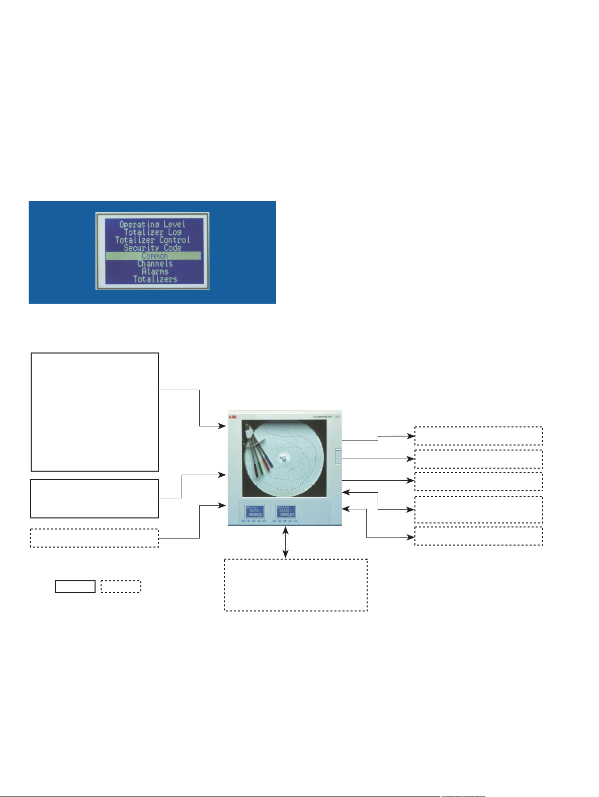
Clear, Intuitive Display Menus
Comprehensive Process Information
The C1300 incorporates up to two graphical display panels to
keep the operator informed of process status. Each panel is
capable of displaying up to eight lines of descriptive text to
simplify both configuration and operation of the recorder. The
display technology used increases visibility in high ambient light
conditions.
Simple Operation
The clearly-labelled tactile keypad gives direct access for
operator adjustments and configuration, without the need to
open the recorder's door. Clear text prompts on the digital
displays guide the user through the various menus. A
password-protected security system prevents unauthorized
access to configuration adjustment menus.
2 DS/C1300–EN Rev. I
Page 3
C1300
AND
Channel 1
Alarm
Relay
Annunciator
Logic Equation
Timer 1
12
6
3
9
11
10
1
2
5
7
4
8
Advanced Circular Chart Recorder
Advanced Totalizer Technology
The C1300 features some of the most advanced totalizing
features of any recording instrument, giving it the ability to
autoconfigure totalizers to specific requirements. For example, it
is possible to measure flow in one volumetric unit and totalize in
another; the C1300 automatically calculates the relationship
between the two volume units and configures this information.
No longer is it necessary to deal with unit conversion tables and
timebases.
Totalizer control is enhanced further by reset functionality that is
set in real-time. If the totalizer is required to reset at midnight
every Sunday simply set it to do so. Totalizer logs also eliminate
the requirement for the operator to go to the recorder at the
same time each day to take readings. The totalizer log contains
historical information of the date, time and individual totalizer
values; enabling comparison of process volumes directly from
the front panel of the recorder.
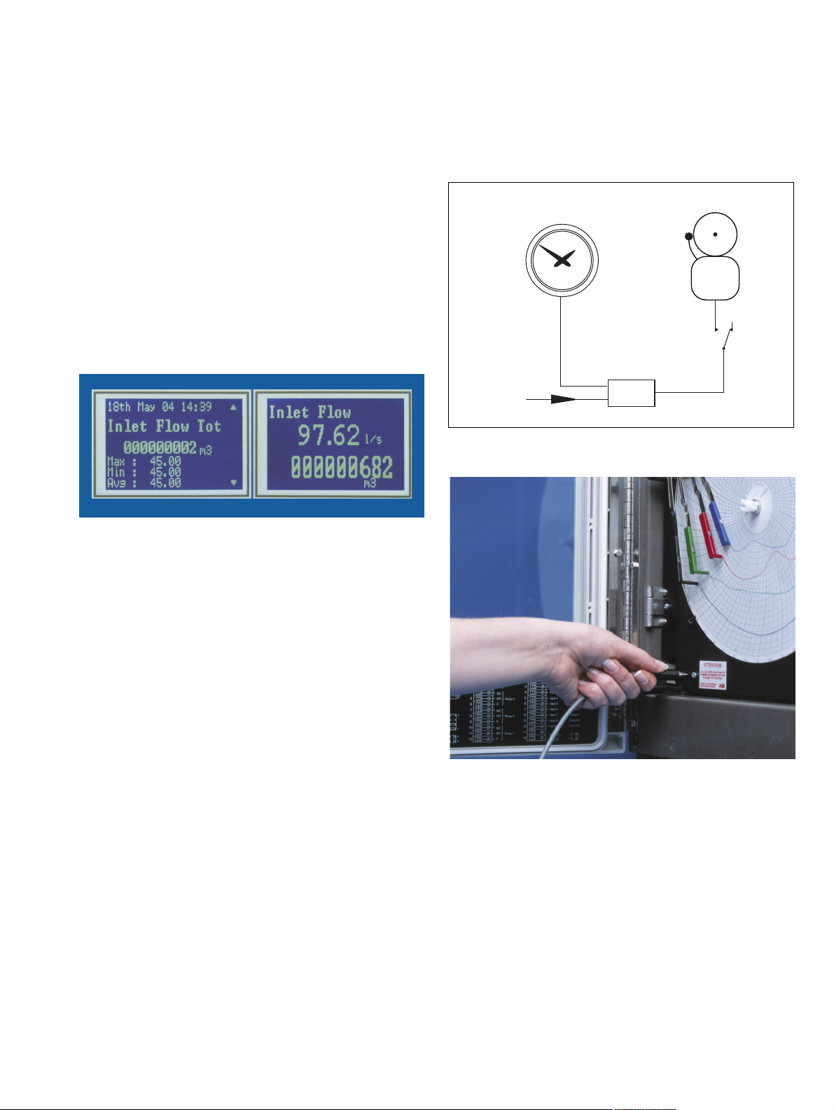
Timers and Clock
The C1300 provides two event timers driven by the recorder's
real-time clock. The timers can be configured to operate relays,
start/stop the chart or trigger other actions within the recorder;
such as allowing alarm annunciation only during night hours.
Alarm Annunciation Enabled During Night Hours Only
Comprehensive Flow Totalizer Displays
PC Configuration Backup
Fitted as standard to every C1300 is a PC Configuration Backup
port. Using this port, an instrument's configuration can be both
uploaded and downloaded to a PC, enabling a backup of a
recorder's configuration to be saved for future use.
Configuration time of multiple units with similar configurations is
also greatly reduced via use of this feature.
Connecting Your PC to the Recorder
DS/C1300–EN Rev. I
3
Page 4
C1300
Flow A
Flow B
Flow C
A + B + C
Math Equation
Totalizer
C1300
Advanced Circular Chart Recorder
Math and Logic
Optional math functions, mass flow calculations and RH tables
are available, enabling the solving of real process problems,
quickly and simply. Math functions include addition, subtraction,
multiplication and division.
Logic capability is provided as standard, for interlocking and
integration of discrete and continuous functions to address a
wide range of process criteria.
Boolean logic functions enable the grouping of alarms to a
single 'common-trouble' relay, saving time and money or
allowing interlocking to create almost infinite combinations of
'If…Then' scenarios.
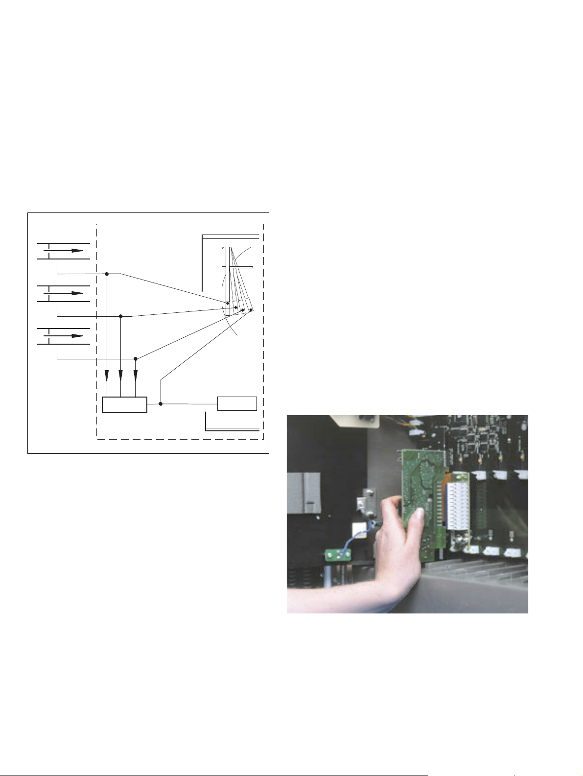
Built to Meet Your Needs
The C1300's modular architecture enables a high level of
hardware choice.
The standard input/output module supplied with every pen
comes complete with a fully isolated universal analog input, a
relay output, transmitter power supply, an isolated analog output
and two digital inputs.
Further input and output capability is provided by a range of
plug-in modules:
Four relays – channel alarm outputs
Eight digital inputs – linked using logic equations
Eight digital outputs – TTL level alarm outputs
True-time event pen (Violet) – event pen is additional to
standard pens
Modbus RS485 communications – interfaces with PCs
Data logging – to Compact Flash card
Expandable for the Future
The C1300 can be upgraded quickly to meet your changing
process requirements.
Additional recording channels, math capability or input and
output functions can be retrofitted on-site using plug-in modules
and easily-fitted pen arms. Input calibration data is stored on
each card, enabling quick changes of input modules without the
need for recalibration.
Changes to input sensors or recording requirements are
accommodated by reconfiguration using the keypad.
Summation of Three Flows
4 DS/C1300–EN Rev. I
Modular Design Enables Unit to be Upgraded Quickly
Modbus RS485 Communications
Communications with PCs or PLCs are achieved via the RS485
serial communications link, enabling the C1300 to serve as the
front end of plant-wide data acquisition systems. Using Modbus
RTU protocol all process inputs and other variables can be read
continuously by a host PC running any of a wide range of
standard SCADA packages.
Page 5
C1300
Pipe-mounting
Wall-mounting
Panel-mounting
Advanced Circular Chart Recorder
4-Pen Recording
Available with up to four trending pens, the C1300 enables pen
ranges to be configured independently from each other and their
corresponding inputs. This enables the pens to be scaled to the
best effect and potentially minimizes the requirement for costly
multiple-scaled consumables. The C1300 also offers a true-time
event-pen facility that ensures that process actions are logged
on the same timeline as Pen 1.
4-pen Recorder with Two Graphical Display Panels
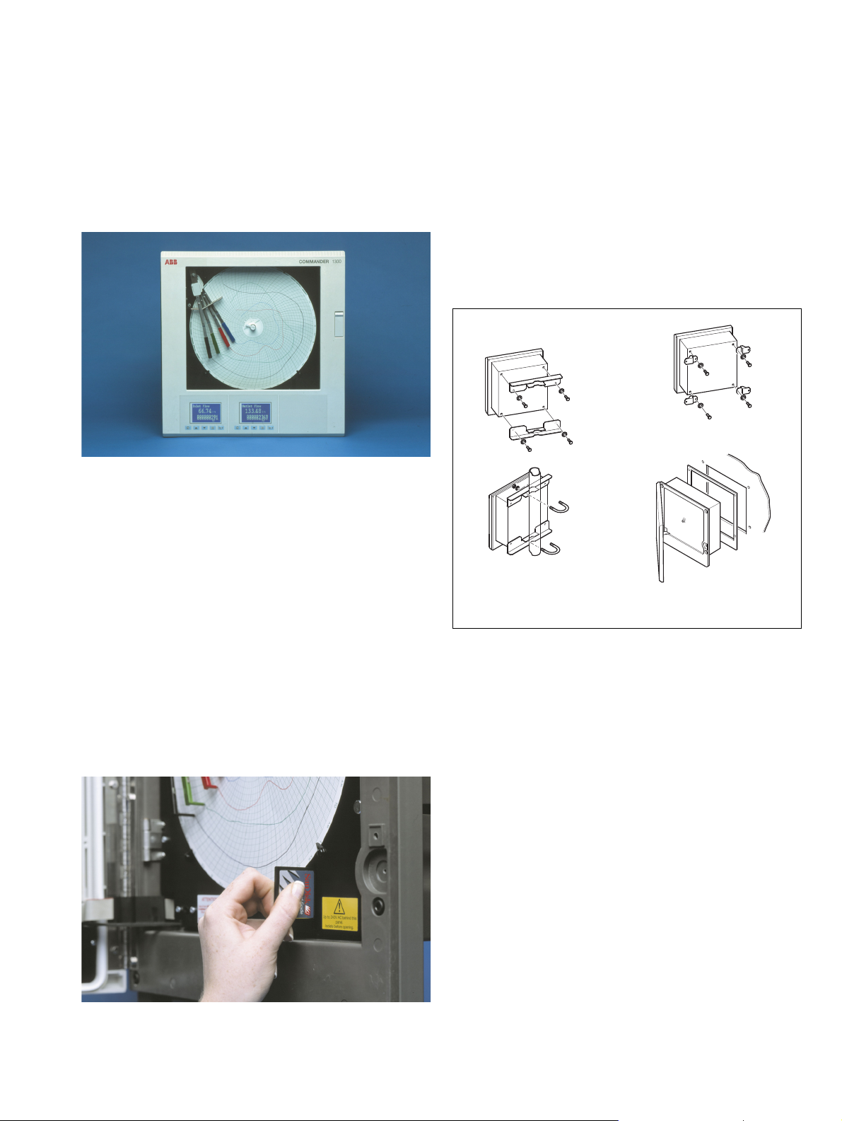
Designed to Survive
Optional NEMA 4X protection ensures the C1300 can survive in
the harshest environments and makes the recorder ideal for use
in panels that are hosed down regularly. The tough,
acid-resistant case provides NEMA 4X rating for all mounting
options.
Easy to Install
A choice of mounting options enables simple installation of the
recorder in a panel, on a wall or on a pipe. Detachable terminal
blocks provide trouble-free connection of input and output
wiring. Mains isolation can be provided by an optional power
switch within the instrument.
Data Logging
The C1300 can be fitted with a data logging option that
automatically stores the totalizer log entries and instantaneous
channel data to a Compact Flash card. Once logged to a card,
ABB's DataManager software can be used to analyze the
totalizer log and create graphs of the instantaneous data.
Simple operation is ensured due to the automatic initiation of
logging upon the insertion of a Compact Flash card and
extremely simple card removal procedure.
As a result of the large capacity of Compact Flash cards,
exceptionally long recording durations can be achieved which
minimizes the requirement for operator intervention to retrieve
data.
The Compact Flash card is located behind the door of the
recorder and can be protected by the optional door lock.
Choice of Mounting Options
Summary
1, 2, 3 or 4 pens
10 in. or 105mm chart size
Standard I/O with each pen includes:
analog input, analog output, transmitter power supply,
relay output and 2 digital inputs
Removing Compact Flash Card
DS/C1300–EN Rev. I
5
Page 6

C1300
Advanced Circular Chart Recorder
Specification
Construction
Size 15.23 in. (h) x 15.04 in. (w) x 5.57 in. (d)
(386.8 x 382.0 x 135mm)
Weight 18lb (8.2kg)
Case material Glassfiber-filled reinforced polyester
Window material Polycarbonate or glass
Door latch High-compression with optional lock
Environmental
Operational temperature range 0° to 55°C (32° to 130°F)
Operational humidity range 5 to 95%RH (non-condensing)
5 to 80%RH (chart only)
Case sealing NEMA 3 (IP54)
NEMA 4X (IP66) (optional)
Installation
Mounting options Panel, wall or pipe
Ter m i n a l typ e Sc r e w
Wire size (max) 14 AWG (I/O), 12 AWG (power)
Operation and Configuration
Programming method Via front panel keys
Security Password-protected menus
Safety
Power Supply
Voltage 100 to 240V AC ±10%
(90V min. to 264V AC max.), 50/60Hz
Consumption <30 VA (typical for full spec. unit)
Line interruption Up to 60ms
Process Inputs and Outputs
General
Noise Rejection Common mode
>120dB at 50/60Hz
Normal (series) mode
>60dB at 50/60Hz
CJC rejection ratio <0.05°C/°C (0.1°F/°F)
Sensor break protection Upscale or downscale drive
Out of range detection 0 to 100% of engineering span
Temperature stability <0.02% of reading/°C
(0.04% of reading/°F) or 1µV/°C
Long-term drift <0.01% of reading or 10µV annually
Input impedance >10MW (mV and V inputs)
39W (mA input)
Analog Inputs
Signal types mV, V, mA, W
Thermocouple types B, E, J, K, N, R, S, T
Resistance thermometer Pt 100
1/2
3/2
Other linearizations x
Sample interval 250ms per channel
Dielectric 500V DC channel/channel
Digital Filter 0 to 60s (programmable)
, x
, x
5/2
, linear
General safety EN61010
Installation category II
Pollution degree 2
Dielectric 500V DC (channel/channel)
2kV DC (channel/ground)
Memory protection Nonvolatile FRAM
Approvals CE
CSA General Safety (option)
UL General Safety (option)
Ty pe Range Low Range High Minimum Span Accuracy
mV 0 150 5 ±0.1% reading or 10µV
V 0 5 0.1 ±0.1% reading or 20mV
mA 0 50 1 ±0.2% reading or 0.2µA
Ohms (low) 0 750 20 ±0.2% reading or 0.1W
Ohms (high) 0 10k 400 ±0.5% reading or 10
Analog Input Performance
6 DS/C1300–EN Rev. I
Page 7

C1300
Advanced Circular Chart Recorder
Ty pe
B –18 1800 0 3270 ±2.0°C (above 200°C) (3.6°F [above 434°F])
E –100 900 –140 1650 ±0.5°C (0.9°F)
J –100 900 –140 1650 ±0.5°C (0.9°F)
K –100 1300 –140 2350 ±0.5°C (0.9°F)
N –200 1300 –325 2350 ±0.5°C (0.9°F)
R –18 1700 0 3000 ±1.0°C (above 300°) (1.8°F [above 572°F])
S –18 1700 0 3000 ±1.0°C (above 200°C) (1.8°F [above 434°F])
T –250 300 –400 550 ±0.5°C (0.9°F)
PT100 –200 600 –325 1100 ±0.5°C (0.9°F)
Range Low Range High Range Low Range High
°C °F
Accuracy (excluding CJC)
Thermocouple Performance
2-Wire Transmitter Power Supplies
Number 1 per channel
Voltage 24V DC nominal
Drive Up to 25mA
Isolation 500V DC channel-to-channel
Analog Outputs
Typ e 4 t o 2 0 m A
Accuracy ±0.1%
Maximum load 750W
Dielectric 500V DC
Relay Outputs
Type SPDT
Rating (with non-inductive load) 5A at 115/230V AC
Digital Outputs
Type 5V TTL
Rating 5mA per output
Dielectric 500V DC between modules,
no isolation within module
Serial Communications
Connections RS485, 4-wire
Protocol Modbus RTU
Data Logging
Memory card type Compact Flash Type 1
Card size Max. 1Gb
Recording Duration See table below
Digital Inputs
Type TTL or volt-free
Minimum pulse 250ms
Dielectric 500V DC between modules,
no isolation within module
(4 Channels) 128Mb 256Mb 512Mb 1Gb
1 s 1.1 months 2.3 months 4.5 months 8.8 months
5 s 5.6 months 11.3 months 1.9 years 3.6 years
10 s 11.3 months 1.9 years 3.7 years 7.2 years
30 s 2.8 years 5.6 years 11.1 years 21.7 years
60 s 5.6 years 11.1 years 22.2 years 43.4 years
5 min. 27.8 years 55.5 years 111.0 years 216.8 years
10 min. 55.5 years 111.0 years 222.1 years 433.7 years
30 min. 166.5 years 333.1 years 666.2 years 1301.1 years
1 hour 333.1 years 666.2 years 1332.3 years 2602.2 years
6 hour 1998.5 years 3996.9 years 7993.9 years 15613.1 years
Recording Duration
DS/C1300–EN Rev. I
7
Page 8

C1300
Advanced Circular Chart Recorder
Recording System
Pens
Number 1, 2, 3, or 4 (red, green, blue, black)
Response 7 seconds (full scale)
Resolution 0.1% steps
Pen lift Motor-driven, with optional autodrop
Event Pens
Standard 3-position event recording on any channel
Real time 3-position event recording on the same time
line as Pen 1
Chart
Chart size 10 in. or 105mm
Chart speed 1 to 167 hours or 7 to 32 days per revolution
Rotation accuracy <0.5% of rotation time
Graphical Display Panels
Displays
Number 1 (1 or 2 pens) or 2 (3 or 4 pens)
Type High contrast 128 x 64 STN dot matrix LCD
(graphics) module
Status indicators Indicate channel number on display
Alarm indicators Indicate channel with active alarms
Logic Equations
Number 4
Function OR, AND
Inputs Alarm states, digital inputs, totalizers, logic
Outputs Relays, digital outputs, chart stop,
alarm acknowledge
Advanced Software Functions
Totalizers
Number Up to 4
Size 999,999,999 max.
Output External counter driver, 'wrap' pulse signal
Totalizer log Max. 21 entries per totalizer
Math
Number of equations 4
Type +, –, x, ÷, low & high select, maximum,
minimum, average, mass flow, RH
Timers
Number 2
Type Real-time clock driven event,
adjustable duration
Output Relay, digital output, logic equation
Panel keys
Function Programming access, increment/decrement,
pen lift and menu key
Alarms and Logic
Alarms
Number 4 per channel
Type High/low process, fast/slow rate of change,
time delay
Adjustments Hysteresis, time delay
Alarm indicators Indicate channel with active alarms
I/O Per Module
Module Type
Analog I/P Analog O/P Tr a n s . P SU Relays Digital I/P Digital O/P Comms.
Standard I/O 1 1 1 1 2 4
4 relays 4 2
8 digital I/P 83
8 digital O/P 83
RS485 comms. 11
EMC
Emissions and Immunity
Meets requirements of:
EN50081-2
EN50082-2
EN61326 for an industrial environment
CE Mark
Max. No. Per
Instrument
Option Module Types
8 DS/C1300–EN Rev. I
Page 9

C1300
3
6
+
e Thermocouple
1
2
7
8
9
10
11
12
Analog Output
+
Relay
Output
Normally Open
Common
Normally Closed
Logic Inputs
Common
Logic 1
Logic 2
Analog Input see b to h
3
4
5
6
Summary of Connections
4
6
+
+
Tx
d 2-wire Transmitter
3
6
+
g Low Voltage (mV)
3
4
+
c Current
(non 2-wire Transmitters)
3
6
+
b Voltage
Standard Input/Output Modules
1
2
7
8
9
10
11
12
3
4
5
6
Normally Closed
Normally Open
Relay 1
Common
Normally Closed
Normally Open
Relay 2
Common
Normally Closed
Normally Open
Relay 3
Common
Normally Closed
Normally Open
Relay 4
Common
Four-Relay Output Module
1
2
7
8
9
10
11
12
3
4
5
6
Common
Input 1
Common
Input 7
Input 8
Input
Connections
Input 5
Input 6
Input 3
Input 4
Input 2
Common
Output 1
Common
Output 7
Output 8
Output
Connections
Output 5
Output 6
Output 3
Output 4
Output 2
or
Digital Input/Output Module
4
5
6
Red
White
Red
f 3-wire RTD
5
6
White
Red
Link
4
h 2-wire RTD and
Resistance
Power Switch (Optional)
Fuse (Optional)
X
Line
Neutral
Earth (Ground) Stud
2 3 4 5 6
Advanced Circular Chart Recorder
Electrical Connections
Power Supply Connections
DS/C1300–EN Rev. I
9
Page 10

C1300
8.3 (0.32)
320.8 (12.63)
320.8
(12.63)
56.8
(2.23)
30.1 (1.18)30.1 (1.18)
66 (2.60)
35.1 (1.38)
22.4 (0.94)
183.4
(7.22)
36.6 (1.44) Typical Space Between
Adjacent Knockout Centers
33 (1.30)
386.8
(15.23)
382 (15.04)
323
(12.72)
323
(12.72)
Panel Cut-out Size
360.4
(14.19 )
285.75
(11.25)
355.6
(14.00)
16.25 (0.64)
43.2
(1.70)
Wall-mount Dimensions
4 holes 7.14 (0.281) dia.
or tap for
1
/4 in. thread
Dimensions in mm (in.)
Advanced Circular Chart Recorder
Overall Dimensions
10 DS/C1300–EN Rev. I
Page 11

C1300
Advanced Circular Chart Recorder
Ordering Information
C1300 Advanced Circular Chart Recorder 131 X XXXXXXXXXXXXXXXX
Pens
One Pen (Red)
Two Pens (Red, Green)
Three Pens (Red, Green, Blue)
Four Pens (Red, Green, Blue, Black)
Chart Type
Standard (ER/C)
KPC 105 PX and PXR type charts
Chessell Brand charts
Electrical Code
Standard
CSA approved
UL approved
Software Options
None
1 Totalizer, Math & Timers
2 Totalizers, Math & Timers
3 Totalizers, Math & Timers
4 Totalizers, Math & Timers
Environmental Protection
IP54 & NEMA3
IP66 & NEMA4X
Door Color
ABB standard
Grey
Window Material
Glass
Polycarbonate
Door Lock
No lock
Lock fitted
Power Supply
100 to 240V AC ±10% (90V min. to 264V) max.
100 to 240V AC ±10% (90V min. to 264V) max. with on/off switch
I/O Modules Module Type (see key on back page)
Module Position 2/Channel 2 Input* 01
Module Position 3/Channel 3 Input* 0 1
Module Position 4/Channel 4 Input* 013456
Module Position 5 0 3 4 5 8
Module Position 6 0458L
Special Settings
Company standard
Customer setting
Special
* On 2, 3 or 4 pen instruments, a standard I/O module is always fitted in the corresponding module position
(enter '0' in the corresponding order code field)
1
2
3
4
J
K
C
A
C
U
0
1
2
3
4
0
N
0
G
G
P
0
L
1
2
STD
CUS
SXX
DS/C1300–EN Rev. I
11
Page 12

C1300
Advanced Circular Chart Recorder
Standard Accessories
(supplied with each recorder)
Set of pens
Pack of 10 charts (0 to 100, 24 hour)
Wall-mount kit
Optional Accessories
Part No. Description
C100/0051 PC configuration backup cable
C1900/1713 Pipe-mount kit
SW/DATMGR DataManager Software
B12028 Card Reader
B11867 Compact Flash Card
12 DS/C1300–EN Rev. I
Page 13

C1300
65432
2 3 4 5 61
Advanced Circular Chart Recorder
…Ordering Information
Module Positions
0 No module fitted/pen input channel
1 Standard input/output
3Four relays
4 Eight digital inputs
5 Eight digital outputs
6 True-time event pen –Violet (additional to standard pens)
8 Modbus RS485 communications
L Data logging
Key to Module Types
DS/C1300–EN Rev. I
13
Page 14

C1300
Advanced Circular Chart Recorder
Notes
14 DS/C1300–EN Rev. I
Page 15

C1300
Advanced Circular Chart Recorder
DS/C1300–EN Rev. I
15
Page 16

Contact us
ABB Limited
Process Automation
Howard Road
St. Neots
Cambridgeshire PE19 8EU
UK
Tel: +44 (0)1480 475321
Fax: +44 (0)1480 217948
ABB Inc.
Process Automation
125 E. County Line Road
Warminster
PA 18974
USA
Tel: +1 215 674 6000
Fax: +1 215 674 7183
www.abb.com
Note
We reserve the right to make technical changes or
modify the contents of this document without prior
notice. With regard to purchase orders, the agreed
particulars shall prevail. ABB does not accept any
responsibility whatsoever for potential errors or
possible lack of information in this document.
We reserve all rights in this document and in the
subject matter and illustrations contained therein.
Any reproduction, disclosure to third parties or
utilization of its contents in whole or in parts – is
forbidden without prior written consent of ABB.
Copyright© 2011 ABB
All rights reserved
3KXR200102R1001
Modbus™ is a trademark of Modicon, Inc.
DS/C1300–EN Rev. I 07.2011
 Loading...