

ABB ACS880-01 Installation Manual
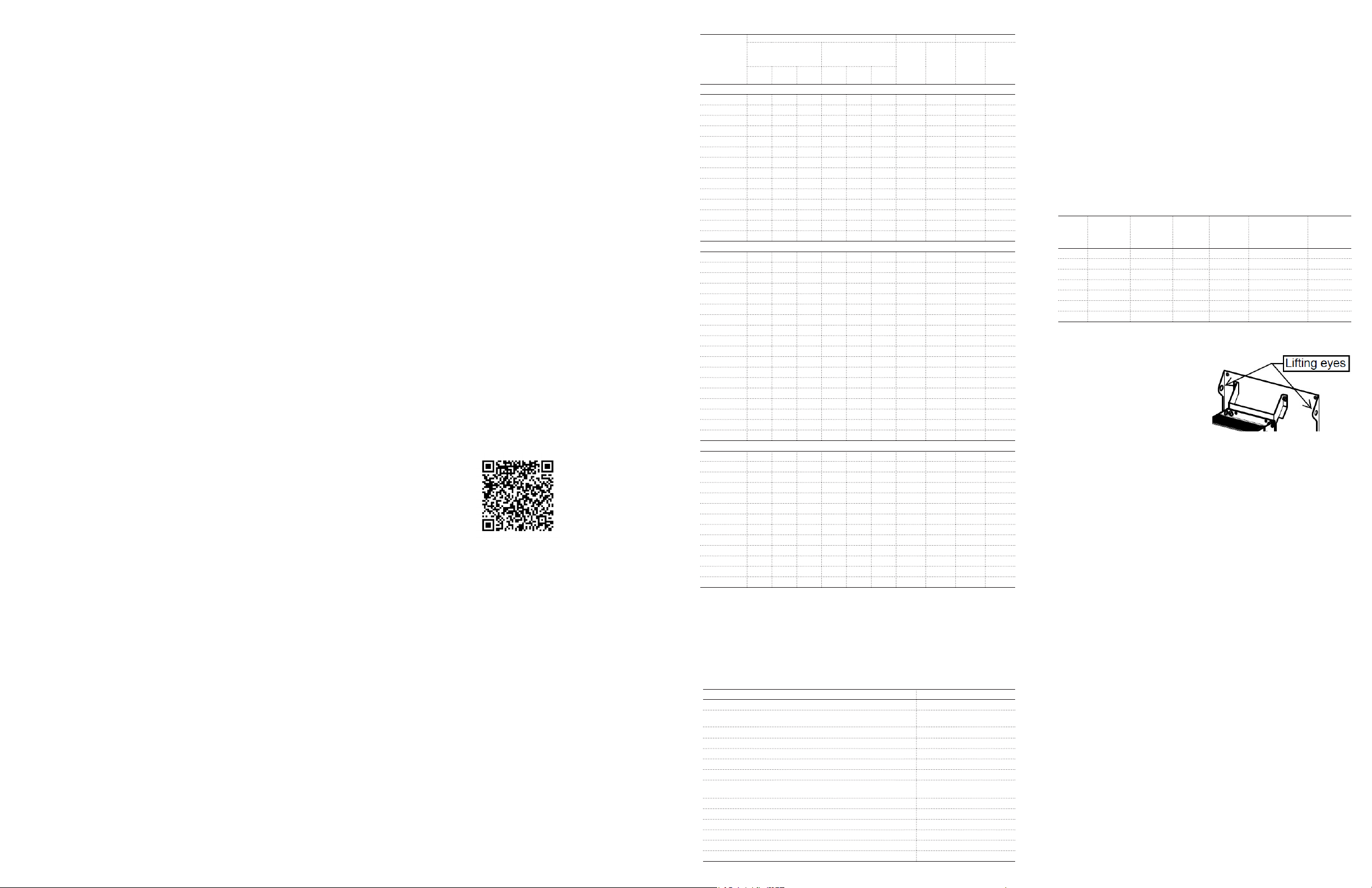
ABB AC Drives
ACS880-01…+C212 Extension Box,
1 – 60 HP at 230V
1 – 150 HP at 480V
7.5 – 125 HP at 575V
Document No. 3AXD50000043508 Rev. 0
ACS880-01…+C212 Extension Box Installation Quick Guide
The ACS880-01…+C212 Extension Box is an ACS880-01 wall-mounted
variable frequency AC drive on a back panel with an electrical box for
additional devices. Standard devices include line fuses to protect the drive
and a power distribution block. Optional devices includes a line disconnect switch, control power transformer, switches and pilot lights as well as
ACS880-01 options for eldbus, input/output adapters, special software,
etc.
1. Safety in installation and maintenance
Electrical safety
These warnings are intended for all who work on the drive, motor cable or
motor.
WARNING! Ignoring the following instructions can cause physical injury or
death, or damage to the equipment:
– Only qualied electricians are allowed to install and maintain the drive.
– Never work on the drive, motor cable or motor when main power
is applied. After disconnecting the input power, always wait for 5
minutes to let the intermediate circuit capacitors discharge before you
start working on the drive, motor or motor cable.
– Always ensure by measuring with a multimeter (impedance at least 1
Mohm) that:
– Voltage between drive input phases L1, L2 and L3 and the frame
is close to 0 V
– Voltage between terminals UDC+ and UDC- and the frame is
close to 0 V.
– Do not work on the control cables when power is applied to the drive
or to the external control circuits. Externally supplied control circuits
may cause dangerous voltages inside the drive even when the main
power on the drive is switched off.
– Do not make any insulation or voltage withstand tests on the drive.
– Do not connect the drive to a voltage higher than what is marked
on the type designation label. Higher voltage can activate the brake
chopper and lead to brake resistor overload, or activate the overvolt-
age controller what can lead to motor rushing to maximum speed.
Note:
– The motor cable terminals on the drive are at a dangerously high
voltage when the input power is on, regardless of whether the motor
is running or not.
– The DC terminals (UDC+, UDC-) carry a dangerous DC voltage (over
500 V) when internally connected to the intermediate DC circuit.
– Depending on the external wiring, dangerous voltages (115 V, 220
V or 230 V) may be present on the terminals of relay outputs (XRO1,
XRO2 and XRO3).
– The Safe torque off function does not remove the voltage from the
main and auxiliary circuits. The function is ineffective against deliber-
ate sabotage or misuse.
IMPORTANT: Other Safety Information
Before handling the equipment or connecting voltage to the drive, see
ACS880 Hardware Manual (3AUA0000078093) Chapter 1 Safety instructions for additional information on grounding, lifting, starting up and
operating the equipment.
This guide instructs briey how to install the drive. For more detailed
instructions, engineering guide lines, technical data and complete safety
instructions, see the ACS880 Hardware Manual in the accompanying CD
or available here: www.abb.com/drives: Select Document Library and
search for document number 3AUA0000078093 [English].
2. List of related manuals
Drive hardware manuals and guides Code (English)
ACS880-01 hardware manual 3AUA0000078093
ACS880-01 quick installation guide for frames R1 to R3 3AUA0000085966
ACS880-01 quick installation guide for frames R4 and R5 3AUA0000099663
ACS880-01 quick installation guide for frames R6 to R9 3AUA0000099689
ACS880-01 drives for cabinet installation (option +P940,
+P944) supplement 3AUA0000145446
ACS880-01 assembly drawings for cable entry boxes of
P21 frames R5 to R9 3AUA0000119627
ACS-AP-x assistant control panels user’s manual 3AUA0000085685
Vibration dampers for ACS880-01 drives (frames R4, R5,
option +C131) installation 3AXD50000010497
Vibration dampers for ACS880-01 drives (frames R6, R9,
option +C131) installation 3AXD50000013389
ACS880-01 marine type-approved drives (option +C132)
supplement 3AXD50000010521
Drive rmware manuals and guides
ACS880 standard control program rmware manual 3AUA0000085967
Quick start-up guide for ACS880 drives with primary
control program 3AUA0000098062
Option manuals and guides
FDIO-01 digital I/O extension module user’s manual EN 3AUA0000124966
Other manuals and quick guides for I/O extension modules,
eldbus adapters, etc. Multiple
You can nd manuals and other product documents in PDF format on
the Internet. See section manuals not available in the Document library,
contact your local ABB representative
The QR code below opens an online listing of the manuals applicable to
this product.
ACS880-01 manuals
3. Packing List
The following items are included in the box:
1. ACS880 Extension Box drive unit (See ratings chart for size and
variants)
2. ACS880 Extension Box Quick Guide (this document)
3. ACS880 Quick Start Guide
4. ACS880 Manuals on CD
5. ACS880 Extension Box schematic diagram and layout drawing
4. Drive Ratings Table and Plus Code Variants
Type code
(110% overload for
ACS880-01-
240 VAC (range 208 to 240 VAC); Power ratings are valid at nominal voltage 230 VAC, 60 Hz
04A6-2+C212 4.4 1 0.75 3.7 0.75 0.55 F2-R1 57 F12-R1 88
06A6-2+C212 6.3 1.5 1.1 4.6 1 0.75 F2-R1 57 F12-R1 88
07A5-2+C212 7.1 2 1.5 6.6 1.5 1.1 F2-R1 57 F12-R1 88
10A6-2+C212 10.1 3 2.2 7.5 2 1.5 F2-R1 57 F12-R1 88
16A8-2+C212 16 5 4 10.6 3 3 F2-R2 62 F12-R2 93
24A3-2+C212 23.1 7.5 5.5 16.8 5 4 F3-R2 54 F12-R2 93
031A-2+C212 29.3 10 7.5 24.3 7.5 5.5 F3-R3 58 F12-R3 97
046A-2+C212 44 15 11 38 10 7.5 F4-R4 82 F12-R4 116
061A-2+C212 58 20 15 45 15 11 F4-R4 84 F12-R4 116
075A-2+C212 71 25 18.5 61 20 15 F5-R5 118 --- ---
087A-2+C212 83 30 22 72 25 18.5 F5-R5 118 --- ---
115A-2+C212 109 40 30 87 30 22 F5-R6 166 --- ---
145A-2+C212 138 50 37 105 40 30 F5-R6 166 --- ---
170A-2+C212 162 60 45 145 50 37 F6-R7 210 --- ---
500 VAC (range 380 to 500 VAC); Power ratings are valid at nominal voltage 460 VAC, 60 Hz
02A1-5+C212 2.1 1 0.75 1.7 0.75 0.55 F2-R1 57 F12-R1 88
03A0-5+C212 3 1.5 1.1 2.1 1 0.75 F2-R1 57 F12-R1 88
03A4-5+C212 3.4 2 1.5 3 1.5 1.1 F2-R1 57 F12-R1 88
04A8-5+C212 4.8 3 2.2 3.4 2 1.5 F2-R1 57 F12-R1 88
07A6-5+C212 7.6 5 4 5.2 3 3 F2-R1 57 F12-R1 88
11A0-5+C212 11 7.5 5.5 7.6 5 4 F2-R1 57 F12-R1 88
014A-5+C212 14 10 7.5 11 7.5 5.5 F2-R2 62 F12-R2 93
021A-5+C212 21 15 11 14 10 7.5 F3-R2 54 F12-R2 93
027A-5+C212 27 20 15 21 15 11 F3-R3 58 F12-R3 97
034A-5+C212 34 25 18.5 27 20 15 F3-R3 58 F12-R3 97
040A-5+C212 40 30 22 34 25 18.5 F4-R4 84 F12-R4 116
052A-5+C212 52 40 30 40 30 22 F4-R4 84 F12-R4 116
065A-5+C212 65 50 37 52 40 30 F5-R5 118 --- ---
077A-5+C212 77 60 45 65 50 37 F5-R5 118 --- ---
096A-5+C212 96 75 55 77 60 45 F5-R6 166 --- ---
124A-5+C212 124 100 75 96 75 55 F6-R6 188 --- ---
156A-5+C212 156 125 90 124 100 75 F6-R7 210 --- ---
180A-5+C212 180 150 110 156 125 90 F6-R7 210 --- ---
600 VAC (range 525 to 690 VAC); Power ratings are valid at nominal voltage 575 VAC, 60 Hz
07A3-7+C212 9 7.5 5.5 6.1 5 4 F5-R5 118 --- ---
09A8-7+C212 11 10 7.5 9 7.5 5.5 F5-R5 118 --- ---
14A2-7+C212 17 15 11 11 10 7.5 F5-R5 118 --- ---
018A-7+C212 22 20 15 17 15 11 F5-R5 118 --- ---
022A-7+C212 27 25 18.5 22 20 15 F5-R5 118 --- ---
026A-7+C212 32 30 22 27 25 18.5 F5-R5 118 --- ---
035A-7+C212 41 40 30 32 30 22 F5-R5 118 --- ---
042A-7+C212 52 50 37 41 40 30 F5-R5 118 --- ---
049A-7+C212 52 50 37 41 40 30 F5-R5 118 --- ---
061A-7+C212 62 60 45 52 50 37 F5-R6 166 --- ---
084A-7+C212 77 75 55 62 60 45 F5-R6 166 --- ---
098A-7+C212 99 100 75 77 75 55 F6-R7 210 --- ---
119A-7+C212 125 125 90 99 100 75 F6-R7 210 --- ---
Notes:
Ratings apply at an ambient temperature of 40°C (104°F) unless otherwise noted.
To achieve the rated motor power given in the table, the rated current of the drive must be higher than or
equal to the rated motor current.
Denitions:
ILD Continuous rms output current allowing 110% overload for 1 minute every 5 minutes.
PLD Typical motor power in light-overload use.
IHD Continuous rms output current allowing 150% overload for 1 minute every 5 minutes.
PHD Typical motor power in heavy-duty use.
Back panel and electrical box below the drive with line fuses and power
distribution block
CPT and digital I/O extension; provides 115 VAC digital inputs and
outputs. Field wiring required.
ILd APLd HPP
Nominal ratings UL Type 1 UL Type 12
Light duty
1 min)
(150% overload for
kWI
A PHd HPP
Ld
2Hd
Heavy duty
1 min)
kW
Frame
Weight
size
(lb)
Hd
Frame
size
+B055
Plus CodeVariant
B055UL Type 12 (IP54)
C212
E205Drive output (dV/dt) lter (10 hp max)
F253Input disconnect switch and handle (replaces power distribution block)
G302Hand-off-auto (HOA) switch
G303Speed potentiometer
G304Control power transformer (CPT)
G304+L526
G327Ready pilot light, white
G328Run pilot light, green
G329Fault pilot light, red
G331Emergency stop push button
G401Start/ Stop push buttons
G404Fault reset push button
Weight
(lb)
+B005
5. Installation
1. Unpacking the unit
Detach the protective wrapping from the shipping pallet.
Remove the unit by unscrewing the four bolts.
2. Mounting:
a. See Technical Specications section for environmental conditions.
b. The unit must be installed in an upright position with the back panel
against a wall.
c. The mounting wall must be vertical, non-ammable and strong
enough to hold the weight of the unit. The material below and
above the unit should be non-ammable.
d. Unit has four (4) mounting holes. (Frame F3 has ve (5).) The
recommended method is to mount the units on horizontal strut
channel. The table below shows mounting dimensions.
Frame Horizontal
Distance
between
Holes
F2 11-1/4 29-3/8 12-3/4 30-1/4 10-1/8 12
F3* 12-1/2 29-1/8 14 30 10-1/8 12
F4 12-1/2 32-1/8 14 33 12-3/8 13
F5 18-1/2 43-1/8 20 44 14-1/4 15-3/8
F6 18-1/2 47-3/8 20 48-1/4 17-3/8 18-1/2
F12 14-1/2 50 16 51 12-1/2 to 13-1/2 14-5/8
Recommended hardware: Four (4) bolts, 3/8 in. (10mm) diameter
* F3 has 3rd hole at top center
** Slots at bottom
(in) (in) (in) (in) (in) (in)
3. Lifting
Lift the unit into place. See ratings
table for weight. Lifting equipment
may be required. Use the back pan-
el lifting eyes which are on units F5
and above. Do NOT use the base
drive lifting eyes which are not rated
for the additional weight of the back panel.
4. Minimum Clearance
a. Above unit: 8 inches (area becomes hot!)
b. Below unit: 12 inches
c. Left side: 0 inches
d. Right side: 2 inches to allow for door swing
e. Between units: 2 inches to allow for door swing
5. Additional Clearance
a. Air ows from bottom to top. Allow enough free space above and
below the drive for cooling air ow, service and maintenance.
b. Allow enough free space in front of the drive for operation, service
and maintenance.
6. Cable entry and exit connections
a. The unit is designed for connection to the top and/or the bottom
of the box for both the motor and the line connections. Conduit
knockouts are provided for this purpose. There are four (4) knocks
on the top and four (4) on the bottom.
b. Knockout Dimensions:
F2 – F5: Suitable for (QTY 2) ½” conduit and (QTY 2) ¾” conduit
F6: Suitable for (QTY 2) ½” conduit and (QTY 2) 1” conduit
F12: Suitable for (QTY 2) ½” conduit and (QTY 2) ¾” conduit
Vertical
Distance
between
Holes**
Overall
Width
Overall
Height
Depth without
Disconnect
Switch
Depth with
Disconnect
Switch

7. Internal wiring connections
a. Line: Phases L1, L2, and L3 bolt to the power distribution block
or the disconnect switch (if equipped). IMPORTANT: When not
equipped with the disconnect switch, the unit must be protected
with class J fuses to provide a 100 kA short circuit current rating
(SCCR). Fuses to be installed upstream of the unit; supplied by
others. See fuse table below.
b. Motor (no lter): Motor leads bolt to terminals T1U, T2V, and T3W
located on the base drive. Remove the base drive cover for easier
access using a Torx screwdriver. See ACS880 Quick Guide and
Hardware Manual for more information.
c. Motor (dV/dt lter): Motor leads bolt to terminals A2, B2 and C2
located on the dV/dt lter.
d. Control: Connect control wires to the colored terminal blocks on
the base drive as needed. See ACS880 Quick Guide and Hardware Manual for more information.
e. Control Power Transformer: If equipped, the secondary of the
control power transformer will be wired to the white 10-position
terminal block. Terminals 1 & 2: L1 (hot); Terminals 3 & 4: L2
(neutral)
f. Digital I/O Extension, FDIO-01: See the FDIO-01 user manual
(3AUA0000124966).
8. Prior to power up
a. IMPORTANT: Prior to power up, carefully review the ACS880
Quick Guide and the ACS880 Hardware Manual.
6. Wire Size and Tightening Torque
1. The list below shows the minimum and maximum wire size each terminal is designed to hold.
2. For cable size recommendations, see ACS880-01 Hardware Manual, chapter: Planning the Electrical Installation, Section: Selecting the
Power Cables.
Power Distribution Block
Frame
Rating @
Size
480 V
F2-R1 1 - 7.5 HP 14 to 2 40 in-lb 18 to 8 7 in-lb 18 to 10* 5 in-lb
F2-R2 10 HP 14 to 2 40 in-lb 18 to 8 7 in-lb 18 to 10** 5 in-lb
F3-R2 15 HP 14 to 2 40 in-lb 18 to 8 7 in-lb 18 to 10 5 in-lb
F3-R3 20 - 25 HP 14 to 2 40 in-lb 14 to 4 18 in-lb 20 to 6 15 in-lb
F4-R4 30 - 40 HP 14 to 2 40 in-lb 14 to 4 18 in-lb 20 to 2 28 in-lb
F5-R5 50 - 60 HP 14 to 2 40 in-lb M8 x 25 bolt 11 ft-lb 10 to 2/0 4 ft-lb
F5-R6 75 HP 14 to 2/0 10 ft-lb M8 x 25 bolt 11 ft-lb 4 to 300 MCM 22 ft-lb
F6-R6 100 HP 14 to 2/0 10 ft-lb 4 to 300MCM 23 ft-lb 4 to 300 MCM 22 ft-lb
F6-R7 125 - 150 HP 4 to 500 MCM 31 ft-lb 4 to 300MCM 23 ft-lb 3/0 to 400 MCM 29 ft-lb
100 - 125 HP
F6-R7
@ 575V
F12-R1 1 - 7.5 HP
F12-R2 10 - 15 HP 14 to 4 35 in-lb
F12-R3 20 - 25 HP 14 to 4 35 in-lb
F12-R4 30 - 40 HP 8 to 1/0 55 in-lb
* with lter, 14 - 12 ga, 10 in-lb
** with lter 12 - 4 ga, 20 in-lb
Control
10-position terminal block 22 - 10 ga 4.5 in-lb
base drive terminal blocks 24 - 12 ga 5.3 in-lb
Frame Size Rating @ 480 V
F2-R1 1 - 7.5 HP 14 to 2 35 - 50 in-lb 18 to 10 5 in-lb
F2-R2 10 HP 14 to 2 35 - 50 in-lb 18 to 10 5 in-lb
F3-R2 15 HP 14 to 2 35 - 50 in-lb 18 to 10 5 in-lb
F3-R3 20 - 25 HP 14 to 2 35 - 50 in-lb 20 to 6 15 in-lb
F4-R4 30 - 40 HP 14 to 2 35 - 50 in-lb 20 to 2 28 in-lb
F5-R5 50 - 60 HP 14 to 2 35 - 50 in-lb 10 to 2/0 4 ft-lb
F5-R6 75 HP 14 to 2 35 - 50 in-lb 4 to 3/0 14 ft-lb
F6-R6 100 HP 14 to 2 35 - 50 in-lb 4 to 3/0 14 ft-lb
F6-R7 125 - 150 HP 14 to 2 35 - 50 in-lb 4 to 300 MCM 22 ft-lb
F6-R7 100 - 125 HP @ 575V 14 to 2 35 - 50 in-lb 4 to 300 MCM 22 ft-lb
F12-R1 1 - 7.5 HP 8 to 14 40 in-lb 18 to 10 5 in-lb
F12-R2 10 - 15 HP 8 to 14 40 in-lb 18 to 10 5 in-lb
F12-R3 20 - 25 HP 8 to 14 40 in-lb 20 to 6 15 in-lb
F12-R4
30 - 40 HP
(L1, L2, L3)
Wire Size
allowed (ga)
4 to 500 MCM 31 ft-lb 4 to 300MCM 23 ft-lb 4 to 300 MCM 22 ft-lb
14 to 2
Torque
14-10: 35 in-lb
8: 40 in-lb
6-4: 45 in-lb
2: 50 in-lb
allowed (ga)
Disconnect Switch
(L1, L2, L3)
Wire Size
allowed (ga)
14 to 4 35 in-lb
Panel Ground Terminal
Wire Size
8 to 14 40 in-lb 20 to 2 28 in-lb
Torque
Torque Wire Size Torque
Motor Terminals
(T1/U, T2/V, T3/W)
Wire Size
allowed (ga)
14 to 2
DB Resistor
(R-, R+)
Torque
14-10: 35 in-lb
8: 40 in-lb
6-4: 45 in-lb
2: 50 in-lb
7. Control Power Transformer (G304)
1. Optional control power transformer ratings
a. Input voltage: 208*, 230, 480, 575 Vac 1ph.
*for 208V, convert a 240V unit by changing the
wiring to the transformer primary as indicated below.
b. Output voltage: 115 Vac
c. Rated power: 100 VA
d. Available power: 100 VA (drive control power is not fed from
this device)
e. Heat dissipation: 21 Watts
2. Primary wiring connections: 230V and 480V units using Micron
B100MBT13RK
a. 480 Volt: H1 and H4
b. 230 Volt: H2 and H4
c. 208 Volt: H3 and H4
3. Primary wiring connections: 575V units using Micron B150WZ13RKF
a. 575 Volt: H1 and H4 (diagram not shown)
8. Drive Output (dV/dt) Filter (E205) -
UL Type 1 only
1. Optional output (dV/dt) lter heat dissipation
Type Code
ACS880-01-02A1-5+C212 1 75 TCI - V1K3A00
ACS880-01-03A0-5+C212 1.5 75 TCI - V1K3A00
ACS880-01-03A4-5+C212 2 75 TCI - V1K4A00
ACS880-01-04A8-5+C212 3 80 TCI - V1K6A00
ACS880-01-07A6-5+C212 5 95 TCI - V1K12A00
ACS880-01-11A0-5+C212 7.5 95 TCI - V1K12A00
ACS880-01-014A-5+C212 10 95 TCI - V1K16A00
Rating at
480 V (HP)
2. External output (dV/dt) lter: Below are recommendations for a lter
located outside the extension box. Filters shown are for 480V motors.
230V motors typically do not require lters. Filters are not readily avail-
able for 575V motors.
Type Code
ACS880-01-021A-5+C212 15 TCI - V1K21A01
ACS880-01-027A-5+C212 20 TCI - V1K27A01
ACS880-01-034A-5+C212 25 TCI - V1K35A01
ACS880-01-040A-5+C212 30 TCI - V1K45A01
ACS880-01-052A-5+C212 40 TCI - V1K55A01
ACS880-01-065A-5+C212 50 TCI - V1K80A01
ACS880-01-077A-5+C212 60 TCI - V1K80A01
ACS880-01-096A-5+C212 75 TCI - V1K110A01
ACS880-01-124A-5+C212 100 TCI - V1K130A01
ACS880-01-156A-5+C212 125 TCI - V1K160A01
ACS880-01-180A-5+C212 150 TCI - V1K200A01
Rating at
480 V (HP)
Filter Loss
(Watts)
Recommended Filter
Replacement Part
9. Switches and Pilot Lights (G3xx, G4xx) -
UL Type 12 only
Variant
G302
G303
G331 Estop
G401
G404 Fault Reset DI-3 Reset
Variant
G327
G328
G329 Fault (red) XRO-3 Faulted Illuminates when the drive has generated a fault
Code
Code
Switch
Hand/Off/
Auto
Speed
Potentiometer
Start/
Stop Push
Button
Pilot Light
Ready
(white)
Run
(green)
Signal
No.
DI-1
DI-3
AI-1
IN1
IN2
DI-1
DI-2
Signal
No.
DIO-1
DIO-2
Signal
Name
Stop (0) /
Start (1)
Hand (0) /
Auto (1)
Speed
Reference
Safe
Torque
Off
Start
Stop
Signal
Name
Output:
Ready
Output:
Running
Description
Three-position selector switch for selecting between hand
(manual), off and automatic mode. IMPORTANT: Must be
congured. Select the hand/auto macro with parameter
96.04. Refer to the ACS880 Firmware Manual, chapter
Application Macros.
Used to select the motor speed while in hand (manual)
mode. Parameter 22.81 shows the actual value.
Red mushroom pushbutton for de-energizing the motor
when the button is pressed. Refer to the ACS880 Hard-
ware Manual, chapter Safe Torque Off Function.
Two (2) push buttons for energizing and de-energizing the
motor. IMPORTANT: Must be congured. Change
parameter 20.01 to (4) “In1P Start; In2 Stop.” Reassign
DI01 or DI02 as Fault Reset input when G302 and hand/
auto macro are used.
Black ush push button for resetting a fault. (Not
compatible with hand/auto macro.)
Description
Illuminates when the drive is able to control the motor
illuminates when the motor is energized by the drive
10. Technical Specications
1.In addition to the following, see ACS880-01 Hardware Manual, chapter:
Technical Specications.
a. Environment: -15 to 40°C (5 to 104°F). -15 to 55°C (5 to 131°F) w/
derate. No frost allowed.
b. Cooling, UL Type 1 (IP21): 3 - 10 HP: forced air via VFD;
15 HP and above: non-ventilated
c. Cooling, UL Type 12 (IP54): non-ventilated
d. Input voltage range – standard: 208-240 V; 380-500 V; 525-690 V
e. Input voltage range – with optional control power transformer
(G304): 208 V, 240 V; 480 V; 575 V
f. Short circuit rating (UL 508c) – standard: 100,000 rms
symmetrical Amperes up to 600 V when protected by class J
fuses. Fuses to be installed upstream of the supplied drive;
supplied by others.
g. Short circuit rating (UL 508c) – with optional input disconnect
(F253): 100,000 rms symmetrical amperes up to 600 V
h. Frequency – standard: 0 - 500 Hz
i. Frequency – with optional dV/dt lter (E205): 0 - 60 Hz
j. Approvals – The ACS880 Extension Box is cULus Listed per
UL508A
11. Fuses
1. Control power transformer
a. Primary: (2) FNQR-1-½
b. Secondary: (1) FNM-2
2. Drive input fuses and overload protection fuses
ACS880 Extension Box
Drive Rating
ACS880-01…
230 V 480 V 575 V UL Class J UL Class T
04A6-2 07A6-5 200 JJS-15
06A6-2 200 JJS-15
07A5-2 07A3-7 200 JJS-15
10A6-2 11A0-5 09A8-7 200 JJS-20
16A8-2 014A-5 200 JJS-25
24A3-2 027A-5 018A-7 200 JJS-40
031A-2 034A-5 022A-7 200 JJS-50
046A-2 052A-5 042A-7 200 JJS-80
061A-2 200 JJS-100
075A-2 200 JJS-125
087A-2 200 JJS-125
115A-2 096A-5 084A-7 200 JJS-150
145A-2 124A-5 119A-7 200 JJS-200
170A-2 600 JJS-250
1. Only needed when disconnect switch option is omitted, the table shows the maximum
Amperage rating of branch circuit fuses to be installed upstream of the supplied drive.
Required to maintain 100 kA SCCR. Fuses supplied and installed by others.
2. Line fuses are included inside the Extension Box
02A1-5 200 JJS-3
03A0-5 200 JJS-6
03A4-5 200 JJS-6
04A8-5 200 JJS-10
05A2-5 200 JJS-10
14A2-7 200 JJS-30
021A-5 200 JJS-35
026A-7 200 JJS-50
040A-5 035A-7 200 JJS-60
049A-7 200 JJS-80
065A-5 200 JJS-90
077A-5 061A-7 200 JJS-110
098A-7 200 JJS-150
156A-5 600 JJS-225
180A-5 600 JJS-300
Maximum
Overcurrent
Protection Fuse
(Amps)
1
Internal Line
2
Fuses
12. Main Cooling Fan Replacement
1. R1 to R5: The main cooling fan is located on the top of the
base drive. Removal and replacement can be done without
removing the base drive from the back panel. Follow the instructions in the ACS880-01 Hardware Manual, chapter: Fans.
2. R6 & R7: The main cooling fan is located on the bottom of the
base drive.
a. Disconnect the drive from the power line. Lock the main
disconnecting device and ensure by measuring that there
is no voltage.
b. Method 1: Remove the fan mounting screws (2) with a
screwdriver by reaching behind the extension box from
below.
c. Method 2: After disconnecting the wires, remove the base
drive from the back panel by removing only the two mounting nuts at the top. (Nuts at the bottom should not be
removed.) Use the lifting eyes on the base drive to remove
and lift the unit to gain access to the cooling fan at the
bottom. To remount the base drive, slide the slots at the
bottom over the two lower studs and drop the base drive
onto the top two studs. Reattach the two nuts. Reconnect the wires.
d. For fan replacement, follow the instructions in the ACS880-
01 Hardware Manual, chapter: Fans.
13. Drive Removal Procedure
Use the same procedure as Method 2 above to remove
the base drive for all of the frames.
3AXD50000043508 REVB Effective: 04/20/2017. Subject to change without notice.
 Loading...