

Page 1

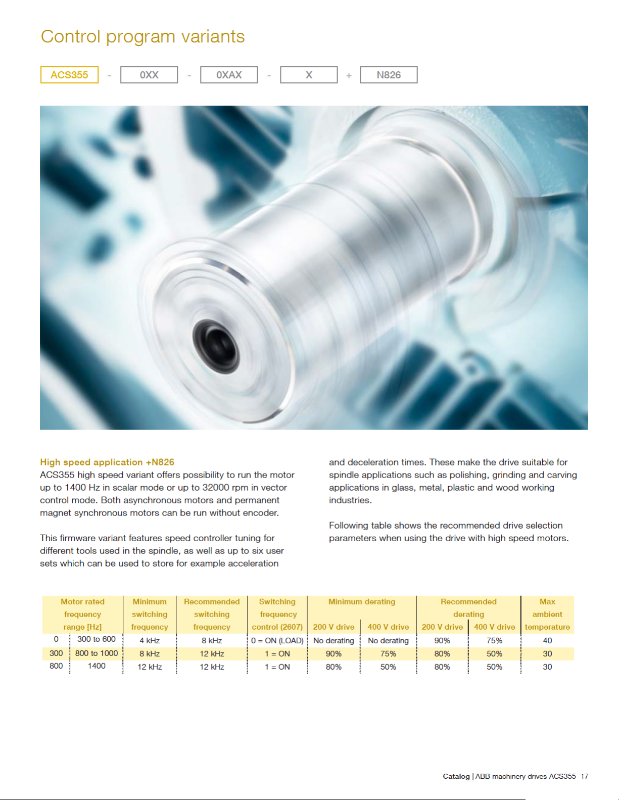
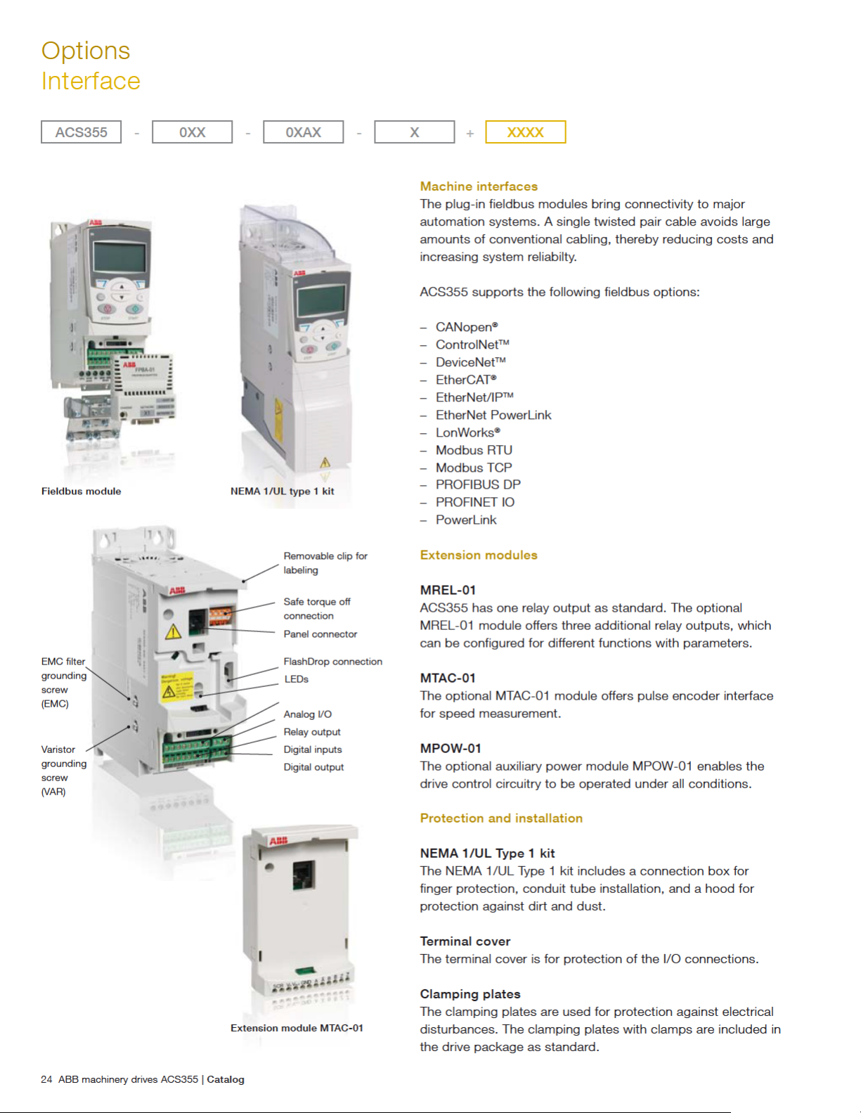
Page 2

Introduction to ACS355
ACS355 - 0XX - 0XAX - X + XXXX
ABB machinery drives
The ABB machinery drives are designed to be fast drives to
install, parameter-set and commission. Thus saving hours
of engineering work. They are highly compact and costeffective. Equipped with cutting-edge intelligence and safety
capability the drives are designed specifically to meet the
production and performance needs of system integrators,
original equipment manufacturers (OEMs) and panel builders,
as well as the requirements of end users in a broad range of
applications.
In the ABB machinery drives portfolio, ACS355 represents the
micro drive range; meeting requirements like compact size,
being optimized for a lower power range, cost-effectiveness,
and ease of use. By choosing an ABB machinery drive,
machine builders not only get all the clever things inside the
drive, but also everything outside it: the entire global ABB.
This means a full range of products and services designed to
support their business.
Contents
2 Introduction to ACS355
4 Little big drives without limiting your business
6 Typical applications
7 How to select a drive
8 Ratings and types
9 Technical data
10 Dimensions and weights
12 Cooling
13 Circuit protection
14 Control connections
15-16 Control program example
17-18 Control program variants for advanced performance
17 High speed application
18 Enhanced sequence programming
19-20 Product variants for application-specific operation
19 High protection class drive
20 Solar pump drive
21 Control program variants
22-36 Options
22 Selecting options
23 Interface
25 Software tools
28 External
36 Compact PLC and AC drive starter kit
37-38 ABB automation products
39 Life cycle services
Applications
ABB machinery drives are designed to meet the requirements
of an extensive range of machinery ap pli ca tions. The drives
are ideal for food and beverage, material handling, lifting,
textile, printing, rubber and plastics, and woodworking
applications.
Highlights
– Exceptionally compact drives and uniform design
– Quick commissioning with application macros and panel
assistants
– Safe torque off function (SIL3) as standard
– Sensorless vector control for induction motors and
permanent magnet motors up to 599 Hz
– Built-in braking chopper
– IP66 product variant for harsh environments and solar
pump drive variant available
2 ABB machinery drives ACS355 | Catalog
Page 3
Catalog | ABB machinery drives ACS355 3
Page 4

Page 5

Page 6

Page 7

Page 8

Ratings and types
ACS355 - 03E - 02A4 - 2 + N830
Type designation
This is the unique reference number (shown above and in
column 4, right) that clearly identifies your drive by current
rating and frame size. Once the drive’s type designation has
been selected, the frame size (column 5) can be used to
determine the drive dimensions, shown on page 10.
Voltages
ACS355 is available in two voltage ranges:
2 = 200 to 240 V
4 = 380 to 480 V
Insert either “2” or “4”, depending on your chosen
construction, current rating, voltage, and option and variant
codes into the type designation shown above.
Ratings IP20/UL Open type/
NEMA 1 option
P
N
[hp]
1-phase AC supply, 200 to 240 V +B063
0.5 0.37 2.4 ACS355-01X-02A4-2 R0 -
1.0 0.75 4.7 ACS355-01X-04A7-2 R1 -
1.5 1.1 6.7 ACS355-01X-06A7-2 R1 -
2.0 1.5 7.5 ACS355-01X-07A5-2 R2 -
3.0 2.2 9.8 ACS355-01X-09A8-2 R2 -
3-phase AC supply, 200 to 240 V +B063
0.5 0.37 2.4 ACS355-03X-02A4-2 R0 R1
0.75 0.55 3.5 ACS355-03X-03A5-2 R0 R1
1.0 0.75 4.7 ACS355-03X-04A7-2 R1 R1
1.5 1.1 6.7 ACS355-03X-06A7-2 R1 R1
2.0 1.5 7.5 ACS355-03X-07A5-2 R1 R1
3.0 2.2 9.8 ACS355-03X-09A8-2 R2 R3
5.0 4.0 17.6 ACS355-03X-17A6-2 R2 R3
7.5 5.5 24.4 ACS355-03X-24A4-2 R3 -
10.0 7.5 31.0 ACS355-03X-31A0-2 R4 -
15.0 11.0 46.2 ACS355-03X-46A2-2 R4 -
3-phase AC supply, 380 to 480 V +B063
0.5 0.37 1.2 ACS355-03X-01A2-4 R0 R1
0.75 0.55 1.9 ACS355-03X-01A9-4 R0 R1
1.0 0.75 2.4 ACS355-03X-02A4-4 R1 R1
1.5 1.1 3.3 ACS355-03X-03A3-4 R1 R1
2.0 1.5 4.1 ACS355-03X-04A1-4 R1 R1
3.0 2.2 5.6 ACS355-03X-05A6-4 R1 R1
5.0 4.0 8.8 ACS355-03X-08A8-4 R1 R1
7.5 5.5 12.5 ACS355-03X-12A5-4 R3 R3
10.0 7.5 15.6 ACS355-03X-15A6-4 R3 R3
15.0 11.0 23.1 ACS355-03X-23A1-4 R3 -
20.0 15.0 31.0 ACS355-03X-31A0-4 R4 -
25.0 18.5 38.0 ACS355-03X-38A0-4 R4 -
30.0 22.0 44.0 ACS355-03X-44A0-4 R4 -
P
[kW]
N
I
[A]
2N
Type designation Frame
size
IP20
Frame
size
IP66
Current rating
Current rating represents the rated continuous drive output
current inside the drive specification. Motor power stated in
the table below states the typical motor power.
Variant code
This code states the factory installed SW variants to the drive.
See pages 16 - 19 for details.
Construction
“01E” within the type designation (shown above) varies
depending on the drive phase and EMC filtering. Choose
below the one you need.
01 = 1-phase
03 = 3-phase
E = EMC filter connected, 50 Hz frequency
U = EMC filter disconnected, 60 Hz frequency
(In case the fi lter is required it can easily be connected)
X within the type designation stands for E or U.
for kW = Typical motor power in 400 V at normal use
P
N
for hp = Typical motor power in 460 V at normal use
P
N
for A = Continuous rms current. 50% overload is allowed
I
2N
for one minute in ten minutes.
8 ABB machinery drives ACS355 | Catalog
Page 9

Technical data
ACS355 - 0XX - 0XAX - X + XXXX
Mains connection
Voltage and
power range
1-phase, 200 to 240 V ± 10%
0.37 to 2.2 kW (0.5 to 3 hp)
3-phase, 200 to 240 V ± 10%
0.37 to 11 kW (0.5 to 15 hp)
3-phase, 380 to 480 V ± 10%
0.37 to 22 kW (0.5 to 30 hp)
Frequency 48 to 63 Hz
Common DC connection
Voltage and
power range
230 V drives, 325 V ±15%
400/480 V drives, 540 ± 15% (common DC
manual)
= Pn of the drive
P
max
Motor connection
Voltage 3-phase, from 0 to U
SUPPLY
Frequency 0 to 599 Hz
Continuous loading
capability
(constant torque at a max.
am bi ent temperature of 40 °C)
Overload capacity
(at a max. ambient temperature
of 40 °C)
Switching frequency
Selectable
Rated output current I
1.5 x I
for 1 minute every 10 minutes
2N
At start 1.8 x I
for 2 s
2N
2N
Default 4 kHz
4 to 16 kHz with 4 kHz steps
Acceleration time 0.1 to 1800 s
Deceleration time 0.1 to 1800 s
Braking Built-in brake chopper as standard
Speed control
Static accuracy
Dynamic accuracy
20% of motor nominal slip
< 1% s with 100% torque step
Torque control
Torque step rise time
Non-linearity
< 10 ms with nominal torque
± 5% with nominal torque
Environmental limits
Ambient temperature -10 to 40 °C (14 to 104 °F), no frost allowed
50 °C (122 °F) with 10% derating
Altitude Rated current available at 0 to 1000 m.
In altitudes from 1000 to 2000 m (3300 to
13,200 ft) above sea level, the derating is
1% for every 100 m (330 ft). If the installation
site is higher than 2000 m (6600 ft) above
sea level, please contact your local ABB
distributor or offi ce for further information.
Relative humidity Lower than 95% (without condensation)
Degree of protection IP20/optional NEMA 1/UL type 1 enclosure
IP66/IP67/UL Type 4X as an option up to
7.5 kW, IP69K available for IP66/IP67 variant
with compatible cable glands
Enclosure colour NCS 1502-Y, RAL 9002, PMS 420 C
Contamination levels
IEC721-3-3
No conductive dust allowed
Transportation
Class 1C2 (chemical gas es)
Class 1S2 (solid particles)
Storage
Class 2C2 (chemical gases)
Class 2S2 (solid particles)
Operation
Class 3C2 (chemical gases)
Class 3S2 (solid particles)
Product compliance
Low Voltage Directive 2006/95/EC
Machinery Directive 2006/42/EC
EMC Directive 2004/108/EC
Quality assurance system ISO 9001
En vi ron men tal sys tem ISO 14001
UL, cUL, CE, C-Tick and GOST R approvals
RoHS compliant
Programmable control connections
Two analog inputs
Voltage signal
Unipolar
Bipolar
Current signal
Unipolar
Bipolar
Potentiometer reference
value
Resolution
Accuracy
0 (2) to 10 V, R
-10 to 10 V, R
0 (4) to 20 mA, R
-20 to 20 mA, R
10 V ± 1% max. 10 mA, R < 10 kΩ
0.1%
± 2%
> 312 kΩ
in
> 312 kΩ
in
= 100 Ω
in
= 100 Ω
in
One analog output 0 (4) to 20 mA, load < 500 Ω
Auxiliary voltage 24 V DC ± 10%, max. 200 mA
Five digital inputs
12 to 24 V, PNP and NPN, programmable
DI5 0 to 16 kHz pulse train
Input impedance
2.4 kΩ
One relay output
Type
Maximum switching voltage
Maximum switching current
Maximum continuous current
NO + NC
250 V AC/30 V DC
0.5 A/30 V DC; 5 A/230 V AC
2 A rms
One digital output
Type
Maximum switching voltage
Maximum switching current
Frequency
Resolution
Accuracy
Transistor output
30 V DC
100 mA/30 V DC, short circuit protected
10 Hz to 16 kHz
1 Hz
0.2%
Serial and Ethernet communication
Fieldbuses
Refresh rate
DeviceNet
TM
Plug-in type
< 10 ms (between drive and fi eldbus module)
5-pin screw type connector, up to 500 kbit/s
baud rate
PROFIBUS DP 9-pin D-connector, up to 12 Mbit/s baud rate
PowerLink 2 pcs RJ-45 connector, 100 Mbit/s baud rate
ControlNet
CANopen
TM
®
2 pcs 8P8C modular jacks
9-pin D-connector, up to 1 Mbit/s
Modbus RTU 4-pin screw type connector, up to 115 kbit/s
baud rate
TM
EtherNet/IP
, Modbus
TCP, PROFINET IO
1 RJ45 connector (FENA-01 and -11) or 2
RJ45 connectors (FENA-21). 10/100Mbit/s
baud rate
LonWorks
®
3-pin screw type connector, up to 78 kbit/s
baud rate
EtherCAT
®
2 pcs RJ-45 connectors, 100 Mbit/s baud rate
Chokes
AC input chokes External option. For re duc ing THD in partial
loads and to comply with EN/IEC 61000-3-12.
AC output chokes External option. To achieve 2x longer motor
cables
Catalog | ABB machinery drives ACS355 9
Page 10

Page 11

Catalog | ABB machinery drives ACS355 11
Page 12

Cooling
Cooling
ACS355 is fi tted with cooling fans as standard. The cooling
air must be free from corrosive substances and must not be
above the maximum ambient temperature of 40 °C (50 °C with
derating). Heat dissipation from IP66/IP67/UL Type 4X drive
equals to the IP20 UL Open values. For more specifi c limits see
the Technical specifi cation - Environmental limits in this catalog.
Cooling air flow
Type designation Frame
1-phase AC supply, 200 to 240 V
ACS355-01X-02A4-2 R0 48 163
ACS355-01X-04A7-2 R1 72 247 24 14
ACS355-01X-06A7-2 R1 97 333 24 14
ACS355-01X-07A5-2 R2 101 343 21 12
ACS355-01X-09A8-2 R2 124 422 21 12
3-phase AC supply, 200 to 240 V
ACS355-03X-02A4-2 R0 42 142 ACS355-03X-03A5-2 R0 54 183 ACS355-03X-04A7-2 R1 64 220 24 14
ACS355-03X-06A7-2 R1 86 295 24 14
ACS355-03X-07A5-2 R1 88 302 21 12
ACS355-03X-09A8-2 R2 111 377 21 12
ACS355-03X-17A6-2 R2 180 613 52 31
ACS355-03X-24A4-2 R3 285 975 71 42
ACS355-03X-31A0-2 R4 328 1119 96 57
ACS355-03X-46A2-2 R4 488 1666 96 57
3-phase AC supply, 380 to 480 V
ACS355-03X-01A2-4 R0 35 121 ACS355-03X-01A9-4 R0 40 138 ACS355-03X-02A4-4 R1 50 170 13 8
ACS355-03X-03A3-4 R1 60 204 13 8
ACS355-03X-04A1-4 R1 69 235 13 8
ACS355-03X-05A6-4 R1 90 306 19 11
ACS355-03X-08A8-4 R1 127 433 24 14
ACS355-03X-12A5-4 R3 161 551 52 31
ACS355-03X-15A6-4 R3 204 697 52 31
ACS355-03X-23A1-4 R3 301 1029 71 42
ACS355-03X-31A0-4 R4 408 1393 96 57
ACS355-03X-38A0-4 R4 498 1700 96 57
ACS355-03X-44A0-4 R4 588 2007 96 57
Heat dissipation Air flow
size
[W] BTU/hr
1)
m3/h ft3/min
2)
-
2)
2)
2)
2)
Free space requirements
Enclosure type Space aboveinSpace belowinSpace on left/right
in
All frame sizes 3.0 3.0 0.0
2)
-
2)
-
2)
-
2)
-
2)
-
IP66 enclosure 3.0 3.0 0.8
X within the type designation stands for E or U.
1)
BTU/hr = British Thermal Unit per hour. BTU/hr is approximately 0.293 Watts.
2)
Frame size R0 with free convection cooling.
12 ABB machinery drives ACS355 | Catalog
Page 13

Circuit protection
Circuit protection
Standard fuses and manual motor protectors can be used
with ACS355 drive. See table below for selecting the correct
fuse for correct drive type.
Selection table
Type designation Frame
size
1-phase AC supply, 200 to 240 V
ACS355-01X-02A4-2 R0 10 gG 10 UL class T MS132-6.3 & S1-M3-25
ACS355-01X-04A7-2 R1 16 gG 20 UL class T MS451-16E 11.0
ACS355-01X-06A7-2 R1 16/20
ACS355-01X-07A5-2 R2 20/25
ACS355-01X-09A8-2 R2 25/35
3-phase AC supply, 200 to 240 V
ACS355-03X-02A4-2 R0 10 gG 10 UL class T MS132-6.3 & S1-M3-25
ACS355-03X-03A5-2 R0 10 gG 10 UL class T MS132-6.3 & S1-M3-25
ACS355-03X-04A7-2 R1 10 gG 15 UL class T MS132-10 & S1-M3-25
ACS355-03X-06A7-2 R1 16 gG 15 UL class T MS451-16E 12.0
ACS355-03X-07A5-2 R1 16 gG 15 UL class T MS451-16E 12.0
ACS355-03X-09A8-2 R2 16 gG 20 UL class T MS451-16E 14.0
ACS355-03X-13A3-2 R2 25 gG 30 UL class T MS451-25E 22.0
ACS355-03X-17A6-2 R2 25 gG 35 UL class T MS451-32E 25.0
ACS355-03X-24A4-2 R3 63 gG 60 UL class T MS451-45E 41.0
ACS355-03X-31A0-2 R4 80 gG 80 UL class T MS495-63E 50.0
ACS355-03X-46A2-2 R4 100 gG 100 UL class T MS495-75E 69.0
3-phase AC supply, 380 to 415 V
ACS355-03X-01A2-4 R0 10 gG 10 UL class T MS132-2.5 & S1-M3-25
ACS355-03X-01A9-4 R0 10 gG 10 UL class T MS132-4.0 & S1-M3-25
ACS355-03X-02A4-4 R1 10 gG 10 UL class T MS132-6.3 & S1-M3-25
ACS355-03X-03A3-4 R1 10 gG 10 UL class T MS132-6.3 & S1-M3-25
ACS355-03X-04A1-4 R1 16 gG 15 UL class T MS132-10 & S1-M3-25
ACS355-03X-05A6-4 R1 16 gG 15 UL class T MS132-10 & S1-M3-25
ACS355-03X-07A3-4 R1 16 gG 20 UL class T MS451-16E 12.0
ACS355-03X-08A8-4 R1 20 gG 25 UL class T MS451-16E 14.0
ACS355-03X-12A5-4 R3 25 gG 30 UL class T MS451-20E 19.0
ACS355-03X-15A6-4 R3 35 gG 35 UL class T MS451-25E 22.0
ACS355-03X-23A1-4 R3 50 gG 50 UL class T MS451-32E 31.0
ACS355-03X-31A0-4 R4 80 gG 80 UL class T MS495-63E 52.0
ACS355-03X-38A0-4 R4 100 gG 100 UL class T MS495-63E 61.0
ACS355-03X-44A0-4 R4 100 gG 100 UL class T MS495-75E 67.0
3-phase AC supply, 440 to 480 V
ACS355-03X-01A2-4 R0 10 gG 10 UL class T MS132-2.5 & S1-M3-25
ACS355-03X-01A9-4 R0 10 gG 10 UL class T MS132-4.0 & S1-M3-25
ACS355-03X-02A4-4 R1 10 gG 10 UL class T MS132-4.0 & S1-M3-25
ACS355-03X-03A3-4 R1 10 gG 10 UL class T MS132-6.3 & S1-M3-25
ACS355-03X-04A1-4 R1 16 gG 15 UL class T MS132-6.3 & S1-M3-25
ACS355-03X-05A6-4 R1 16 gG 15 UL class T MS132-10 & S1-M3-25
ACS355-03X-07A3-4 R1 16 gG 20 UL class T MS132-10 & S1-M3-25
ACS355-03X-08A8-4 R1 20 gG 25 UL class T MS451-16E 11.0
ACS355-03X-12A5-4 R3 25 gG 30 UL class T MS451-20E 16.0
ACS355-03X-15A6-4 R3 35 gG 35 UL class T MS451-20E 18.0
ACS355-03X-23A1-4 R3 50 gG 50 UL class T MS451-32E 26.0
ACS355-03X-31A0-4 R4 80 gG 80 UL class T MS451-45E 43.0
ACS355-03X-38A0-4 R4 100 gG 100 UL class T MS495-63E 51.0
ACS355-03X-44A0-4 R4 100 gG 100 UL class T MS495-63E 56.0
IEC fuses UL fuses Manual motor protector
3) 4)
Trip current setting
5)
5)
5)
5)
5)
5)
5)
5)
5)
5)
5)
5)
5)
5)
5)
5)
5)
[A]
6)
6)
Fuse
1)
type
2)
gG 25 UL class T MS451-20E 16.0
2)
gG 30 UL class T MS451-20E 17.0
2)
gG 35 UL class T MS451-25E 21.0
[A]
Fuse
type
MMP type code
1)
[A]
6.1
4.3
6.1
7.6
2.2
3.6
4.1
6.0
6.9
9.6
1.8
3.0
3.4
5.0
5.8
8.0
9.7
X within the type designation stands
for E or U.
1)
According to EC-60269 standard.
2)
If 50% overload capacity is needed,
use the bigger fuse alternative.
3)
All manual motor protectors listed
are Type E self-protected up to 65 kA.
4)
Manual motor protectors may
require adjusting the trip limit from
the factory setting at or above the
drive input Amps to avoid nuisance
tripping. f the manual motor protector is set to the maximum current
trip level and nuisance tripping is
occurring, then select the next size
MMP. (MS132-10 is the highest size
in MS132 frame size to meet Type
E at 65 kA; the next size up is the
MS451-16E).
5)
S1-M3-25 line side feeder terminal
is needed with manual motor protector to meet Type E self protection
class according to UL and cUL
requirements.
6)
480Y/277V only.
Catalog | ABB machinery drives ACS355 13
Page 14

Page 15
Control program example
ACS355 - 0XX - 0XAX - X + XXXX
on
off
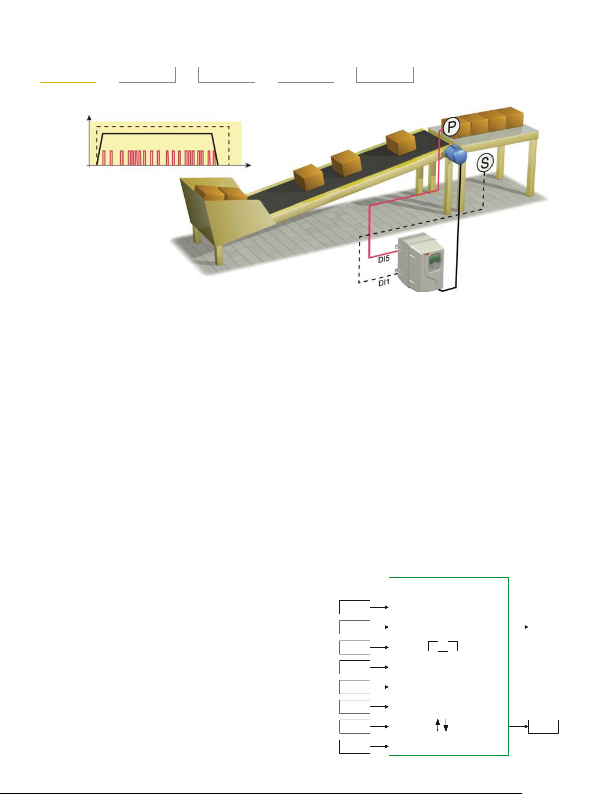
Signal behavior as
function of time in this
conveyor control example
time
The ACS355 drives have many solutions for common
challenges. The following example explains how the
COUNTER STOP function operates within a conveyor
unloading routine. The function stops the conveyor after a
predefined number of boxes have passed the sensor.
The operator starts the conveyor by activating the drive using
switch, S. The switch is connected to digital input 1 (DI1).
The drive accelerates to a constant speed of 30 Hz with a
1 second ramp time.
Meanwhile a sensor, or proximity switch, P, is connected to
digital input 5 (DI5). This sensor generates one pulse, every
time a box on the conveyor passes by. When the required
number of boxes – in this case 20 – have passed the sensor,
the drive stops with a 1 second ramp time.
Parameter settings
Startup data
The correct motor parameters are set within parameter group
99. However, if the current and voltage settings of the motor
and drive match, this is not necessary. The ACS355 also
features vector control, which can be used by setting the
relevant parameters and undertaking an ID run.
Constant speed selection
Parameter 1201 CONST SPEED SEL is set to DI1 [1].
Parameter 1202 CONST SPEED 1 acts as a speed reference
source when digital input 1 is active.
Parameter 1202 CONST SPEED 1 is set to 30 Hz.
Start/Stop functions
Parameter 2101 START FUNCTION is set to AUTO [1], which
is also the default value. If high torque is required for the
conveyor to start, settings DC MAGN [2] can be used.
Parameter 2102 STOP FUNCTION is set to RAMP [2]. Thus
the drive ramps down to 0 at a stop command.
Counter parametrization
Parameter 1904 COUNTER ENABLE is set to DI1 [1]. Counter
is enabled now by digital input 1. When digital input 1 is low,
the counter is not counting.
COUNTER
1904
1905
ENABLE
LIMIT
OUTPUT
Start/Stop/Direction logic
Parameter 1001 EXT1 COMMANDS is set to COUNTER STOP
[24]. Under certain conditions the counter output will modify
the start/stop signal for stopping.
1906
1907
1908
1909
1910
1911
INPUT
RESET
RESET VALUE
DIVIDER
DIRECTION
START/STOP
n
2
VALUE
Catalog | ABB machinery drives ACS355 15
0166
Page 16

Control program example
ACS355 - 0XX - 0XAX - X + XXXX
Parameter 1905 COUNTER LIMIT is set to 20. In this example
the loading station can only hold 20 boxes.
Parameter 1906 COUNTER INPUT is set to PLS IN (DI5)
[1] which is also the default value. Pulse counter P is wired
to digital input (DI5). This digital input can also handle high
frequency pulses up to 10 kHz. If the counter signal edges are
swinging, this parameter can be set to FILTERED DI5 [4].
Parameter 1907 COUNTER RESET is set to DI1 (INV) [-1].
When digital input 1 is low, the counter is reset to a value
determined by parameter 1908 COUNTER RES VAL.
Parameter 1908 COUNTER RES VAL is set to zero, which is
also the default value. The counter, in this example, runs from
0 to 20.
Parameter 1909 COUNT DIVIDER is set to zero, which
is also the default value. This value is used to divide high
frequency pulse numbers to lower values. For example a 1024
pulse incremental encoder would give 1024 pulses in one
revolution. When using count divider 10 (2 to the power of 10)
the counter would count up by 1 after 1024 pulses.
ACS355 control program functions
ACS355 control program provides the following functions:
– Counter start and stop
– Timer start and stop
– Speed compensated stop
– 3 independent supervision functions
– Automatic restart function
– 2 sets of ramping times
– S-curve for ramping
– 7 constant speeds
– 3 critical speed ranges
– Maintenance triggers
– Timed functions
– Configurable fault/protection functions
– 2 process PID functions
– PID sleep function
– PID trim function
– Mechanical brake control
– 8 state sequence programming
– 2 sets of user parameter sets
– Safe torque off
– Parameter lock
Parameter 1910 COUNT DIRECTION is set to UP [0], which is
also the default value.
Parameter 1911 CNTR S/S COMMAND is set to DI1 [1].
Digital input 1 acts as the drive start command. Due to the
setting of parameter 1001 EXT1 COMMANDS, the drive stops
when the counter limit has been reached or digital input 1
goes low.
The counter’s actual value can now be seen from signal 0166.
Acceleration and deceleration settings
Parameter 2201 ACC/DEC 1/2 SEL is set to NOT SEL [0].
Only one ramp is used in this application, thereby ramp
changing is disabled.
Parameter 2202 ACCELER TIME 1 is set to 1s.
Parameter 2203 DECELER TIME 2 is set to 1s.
The ACS355 features the following motor control
functions:
– Current, torque, speed and frequency limits
– Under- and overvoltage controllers
– Starting to the rotating machine
– Linear, squared and user defined U/f curves for scalar
control
– IR compensation for scalar control
– Flux optimization for energy saving
– Flux braking for improved ramping down
– Drive temperature controlled switching frequency control
– Motor noise smoothing
– Sensorless vector control for induction motors
– Sensorless vector control for permanent magnet motors
– Smooth starting function for permanent magnet motors
– PID speed controller in vector controlled mode
– Acceleration compensation
– Speed controller auto tune
– Stand-alone and rotating motor identification runs
– Optional speed feed back for closed loop vector control
16 ABB machinery drives ACS355 | Catalog
Page 17
Page 18
Page 19
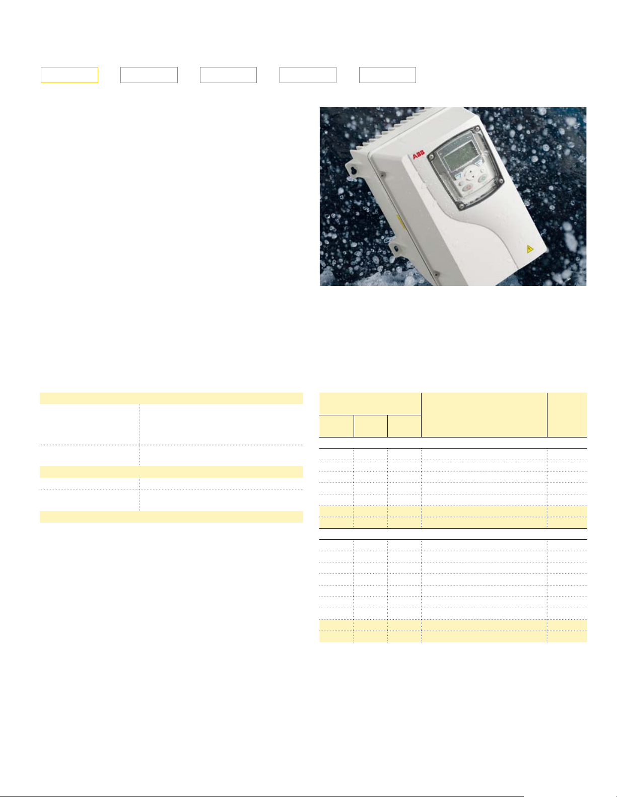
Product variants
ACS355 - 0XX - 0XAX - X + B063
High protection class drive +B063
A range of ABB machinery drives with IP66 protection is
designed for applications exposed to dust, moisture and
cleaning chemicals such as screws, mixers, pumps, fans
and conveyors. Typical industries that benefit from the drive
include food and beverage, textile, ceramics, pulp and paper,
water and wastewater, printing and rubber and plastics.
The heat sink’s cooling fins are completely open from top
to bottom, which allows easy washing to ensure no dirt
adheres to the surfaces. Assistant control panel housed
within a plastic window is designed to resist moist and dusty
atmospheres. Furthermore, the cooling fan is located inside
the drive, thereby eliminating the need for an external cooling
fan and the subsequent maintenance of external moving
parts.
The drive’s hygienic design and use of materials meeting
current hygiene standards, means that the drive traps no
bacteria and can withstand frequent washing. The drive is
certified by NSF.
Mains connection, high protection class drive
Voltage and
power range
Common DC Cannot be used with high degree
Environmental limits, high protection class drive
Ambient temperature -10 to 40 °C (14 to 104 °F), no frost allowed
Degree of protection IP66/IP67/UL Type 4X, indoor use only
Product compliance, high protection class drive
Low Voltage Directive 2006/95/EC
Machinery Directive 2006/42/EC
EMC Directive 2004/108/EC
Quality assurance system ISO 9001
En vi ron men tal sys tem ISO 14001
UL, cUL, CE, C-Tick and GOST R approvals
RoHS compliant
NSF Certified
DIN40050-9 (IP69K)
3-phase, 200 to 240 V ± 10%
0.37 to 4 kW (0.5 to 5 hp)
3-phase, 380 to 480 V ± 10%
0.37 to 7.5 kW (0.5 to 10 hp)
protection class
IP69K with compatible cable glands
Ratings
IP66/IP67/UL Type 4X
P
[hp]
3-phase AC supply, 200 to 240 V
0.5 0.37 2.4 ACS355-03X-02A4-2 + B063 R1
0.75 0.55 3.5 ACS355-03X-03A5-2 + B063 R1
1.0 0.75 4.7 ACS355-03X-04A7-2 + B063 R1
1.5 1.1 6.7 ACS355-03X-06A7-2 + B063 R1
2.0 1.5 7.5 ACS355-03X-07A5-2 + B063 R1
3.0 2.2 9.8 ACS355-03X-09A8-2 + B063 R3
5.0 4.0 17.6 ACS355-03X-17A6-2 + B063 R3
3-phase AC supply, 380 to 480 V
0.5 0.37 1.2 ACS355-03X-01A2-4 + B063 R1
0.75 0.55 1.9 ACS355-03X-01A9-4 + B063 R1
1.0 0.75 2.4 ACS355-03X-02A4-4 + B063 R1
1.5 1.1 3.3 ACS355-03X-03A3-4 + B063 R1
2.0 1.5 4.1 ACS355-03X-04A1-4 + B063 R1
3.0 2.2 5.6 ACS355-03X-05A6-4 + B063 R1
5.0 4.0 8.8 ACS355-03X-08A8-4 + B063 R1
7.5 5.5 12.5 ACS355-03X-12A5-4 + B063 R3
10.0 7.5 15.6 ACS355-03X-15A6-4 + B063 R3
X within the type designation stands for E or U.
for kW = Typical motor power in 400 V at normal use
P
N
for hp = Typical motor power in 460 V at normal use
P
N
for A = Continuous rms current. 50% overload is allowed for one minute
I
2N
in ten minutes.
P
N
[kW]
I
N
2N
[A]
Type designation Frame
size
Catalog | ABB machinery drives ACS355 19
Page 20
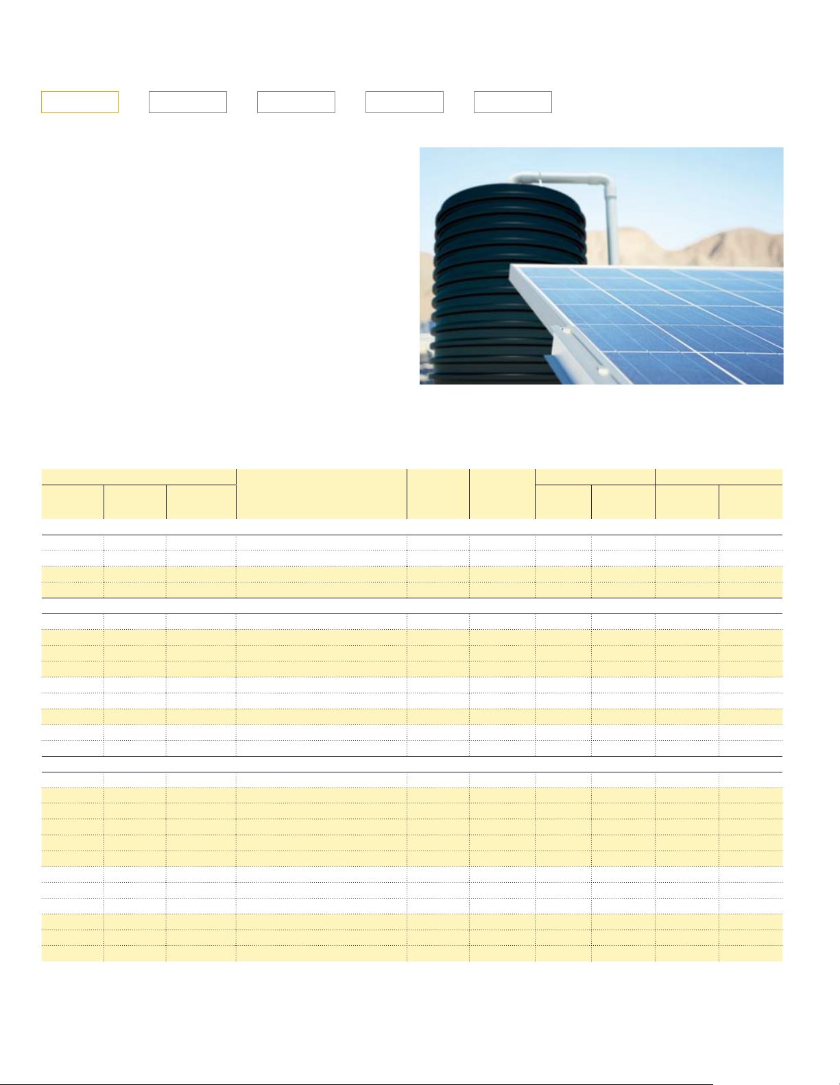
Product variants
ACS355 - 0XX - 0XAX - X + B827
Solar pump drive +N827
Solar pump system consists of a pump, photo voltaic (PV)
panel system fitted to provide enough voltage and power to
the pump, and solar pump drive converting the PV energy of
DC voltage and DC current suitable for AC motor. Pump is
very often submersible pump where motor is integrated to the
pump itself.
ABB solar pump drive is environmentally friendly, with a long
lifetime and low maintenance costs. It is independent from the
grid and produces no pollution or noise. Typical applications
are irrigation, community water supply, fish farming and
agriculture.
This variant offers maximum power point tracking algorithm
to maximize the solar panel output as well as water pumping
specific functions such as dry running detection and flow
calculation.
Ratings Type designation
P
N
hp
1-phase AC supply, 125 to 400 V DC or 200 to 240 V
0.5 0.37 4.7 ACS355-01E-04A7-2 R1 48 243 400 150 420
1.0 0.75 6.7 ACS355-01E-06A7-2 R1 68 243 400 150 420
1.5 1.1 7.5 ACS355-01E-07A5-2 R2 71 243 400 150 420
2.0 1.5 9.8 ACS355-01E-09A8-2 R2 90 243 400 150 420
3-phase AC supply, 125 to 400 V DC or 200 to 240 V
0.5 0.37 3.5 ACS355-03E-03A5-2 R0 33 243 400 150 420
0.75 0.55 4.7 ACS355-03E-04A7-2 R1 41 243 400 150 420
1.0 0.75 6.7 ACS355-03E-06A7-2 R1 59 243 400 150 420
1.5 1.0 7.5 ACS355-03E-07A5-2 R1 61 243 400 150 420
2.0 1.5 9.8 ACS355-03E-09A8-2 R2 79 243 400 150 420
3.0 2.2 13.3 ACS355-03E-13A3-2 R2 50 243 400 150 420
5.0 4.0 24.4 ACS355-03E-24A4-2 R3 219 243 400 150 420
7.5 5.5 31.0 ACS355-03E-31A0-2 R4 252 243 400 150 420
10.0 7.5 46.2 ACS355-03X-46A2-2 R4 380 243 400 150 420
3-phase AC supply, 250 to 800 V DC or 380 to 480 V
0.5 0.37 1.9 ACS355-03E-01A9-4 R0 22 460 800 250 840
0.75 0.55 2.4 ACS355-03E-02A4-4 R1 28 460 800 250 840
1.0 0.75 3.3 ACS355-03E-03A3-4 R1 36 460 800 250 840
1.5 1.1 4.1 ACS355-03E-04A1-4 R1 43 460 800 250 840
2.0 1.5 5.6 ACS355-03E-05A6-4 R1 60 460 800 250 840
3.0 2.2 7.3 ACS355-03E-07A3-4 R1 75 460 800 250 840
5.0 4.0 12.5 ACS355-03E-12A5-4 R3 119 460 800 250 840
7.5 5.5 15.6 ACS355-03E-15A6-4 R3 153 460 800 250 840
10.0 7.5 23.1 ACS355-03E-23A1-4 R3 232 460 800 250 840
15.0 11.0 31.0 ACS355-03E-31A0-4 R4 316 460 800 250 840
20.0 15.0 38.0 ACS355-03E-38A0-4 R4 388 460 800 250 840
25.0 18.5 44.0 ACS355-03E-44A0-4 R4 460 460 800 250 840
P
kW
N
I
2N
A
Frame
size
IP20
Typical
losses W*)
MPPT voltage range DC voltage range
Min Max Min **) Max ***)
*) This is typical maximum losses of drive with basic control panel running at rated power at rated speed at rated conditions.
**) Operation is started with minimum voltage, but 100% AC current cannot be acheived before voltage is equal or higher than minimum MPPT voltage.
***) Panel open circuit voltage should be dimensioned so that it will never in any conditions exceed this level.
20 ABB machinery drives ACS355 | Catalog
Page 21
Control program variants
ACS355 - 0XX - 0XAX - X + N828
Low ambient start +N828
ACS355 low ambient start variant extends the minimum
starting temperature to -39 degrees Celsius. This was done by
reevaluating and adjusting the drive’s low temperature thermal
fault set point to -40 degrees Celsius.
This firmware variant also adds a motor heating feature. With
motor heating feature enabled, a percentage of nominal motor
current is DC inject into the motor windings when the drive is
stopped but still powered. This DC current is used to keep the
internal temperature of the motor and drive above ambient.
Operators and control systems are notified that the motor
and drive still is being supplied with current by an alarm
that is annunciated on the operator’s panel or through the
communication bus.
Combine the ACS355 +N828 drive with an AC500-XC to
provide a Drive and PLC combination good to -40C.
Catalog | ABB machinery drives ACS355 21
Page 22
Page 23
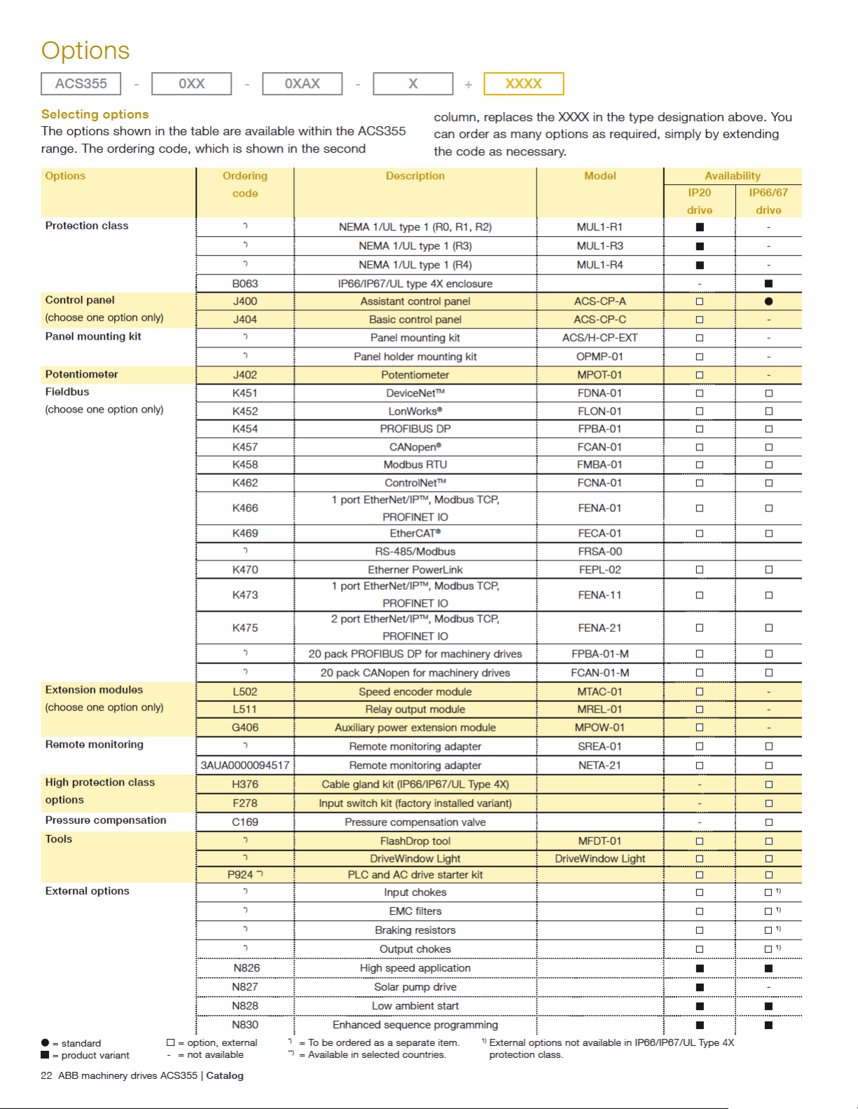
Options
Interface
ACS355 - 0XX - 0XAX - X + XXXX
User interfaces
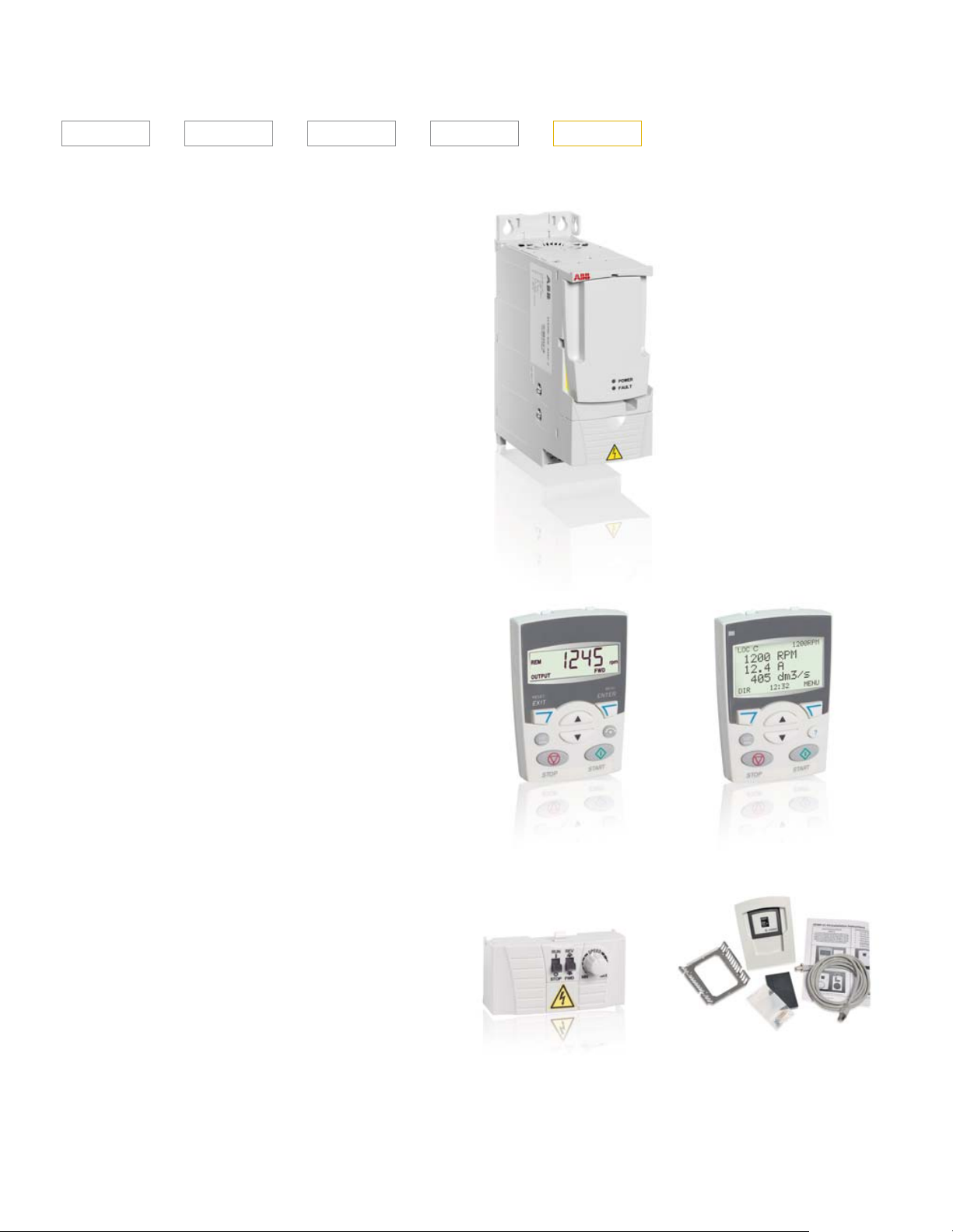
Panel cover
The purpose of the panel cover is to protect the drive’s
connection surfaces.The ACS355 drive is delivered with a
panel cover as standard. In addition there are two alternative
control panels available as options.
Basic control panel
The basic control panel features a single line numeric display.
The panel can be used to control the drive, set the parameter
values or copy them from one drive to another.
Assistant control panel
The assistant control panel features a multilingual alphanumeric
display for easy drive programming. The control panel has
various assistants and a built-in help function to guide the
user. It includes a real time clock, which can be used during
fault logging and in controlling the drive, such as start/stop.
The control panel can be used for copying parameters for
back up or for downloading to another drive. A large graphical
display and soft keys make it extremely easy to navigate. The
drive with IP66/IP67 enclosure has the assistant control panel
as standard.
Panel cover (included as standard)
Potentiometer
Potentiometer MPOT-01 with two switches: start/stop and
forward/reverse. Polarity is selected with DIP switches. No
external power source is needed for the potentiometer.
Panel mounting kits
To attach the control panel to the outside of a larger enclosure,
two panel mounting kits are available. A simple and costefficient installation is possible with the ACS/H-CP-EXT kit,
while the OPMP-01 kit provides a more user-friendly solution,
including a panel platform that enables the panel to be
removed in the same way as a drive-mounted panel. The panel
mounting kits include all hardware required eg, 3 m extension
cables and installation instructions.
Basic control panel
Potentiometer
Assistant control panel
Panel holder mounting kit OPMP-01
Catalog | ABB machinery drives ACS355 23
Page 24
Page 25
Options
Software tools
ACS355 - 0XX - 0XAX - X + XXXX
A separate order line and type code is required for any of
these software tool options.
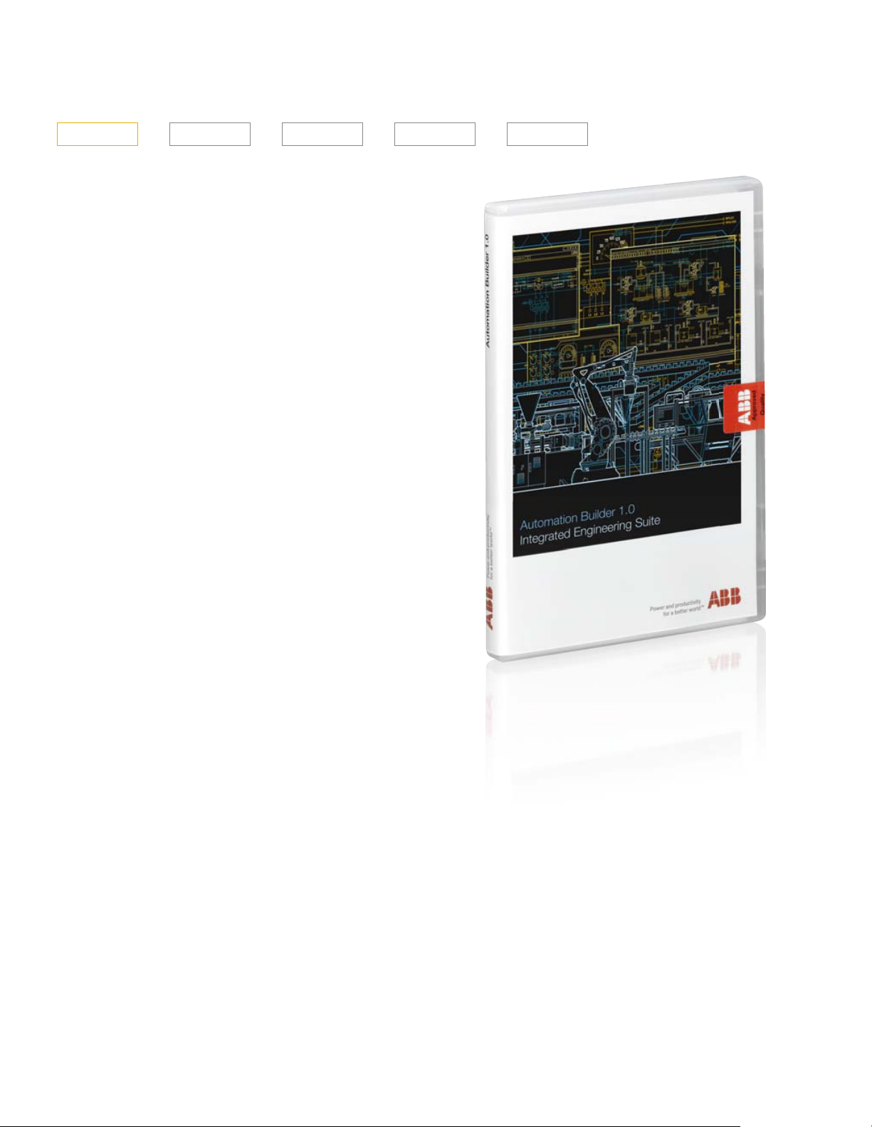
Automation Builder
Automation Builder is an integrated programming,
maintenance and simulation environment for PLCs, safety
products, robots, motion products, drives and control
panels. It combines the proven ABB tools RobotStudio,
Drive Manager, Mint WorkBench, Panel Builder and succeeds
Control Builder Plus, and enables use in IEC 61131-3,
PLCopen, C/ C++, RAPID and MINT programming languages.
Automation Builder minimizes your efforts for managing
project code and data with common data storage, single
project archive, time saving library blocks for device
integration, and a common software installer. The software
includes easy to use libraries for applications in wind, water,
solar, drives, motion, robotics and safety.
Making a joint backup with Automation Builder helps you to
secure and restore your applications.
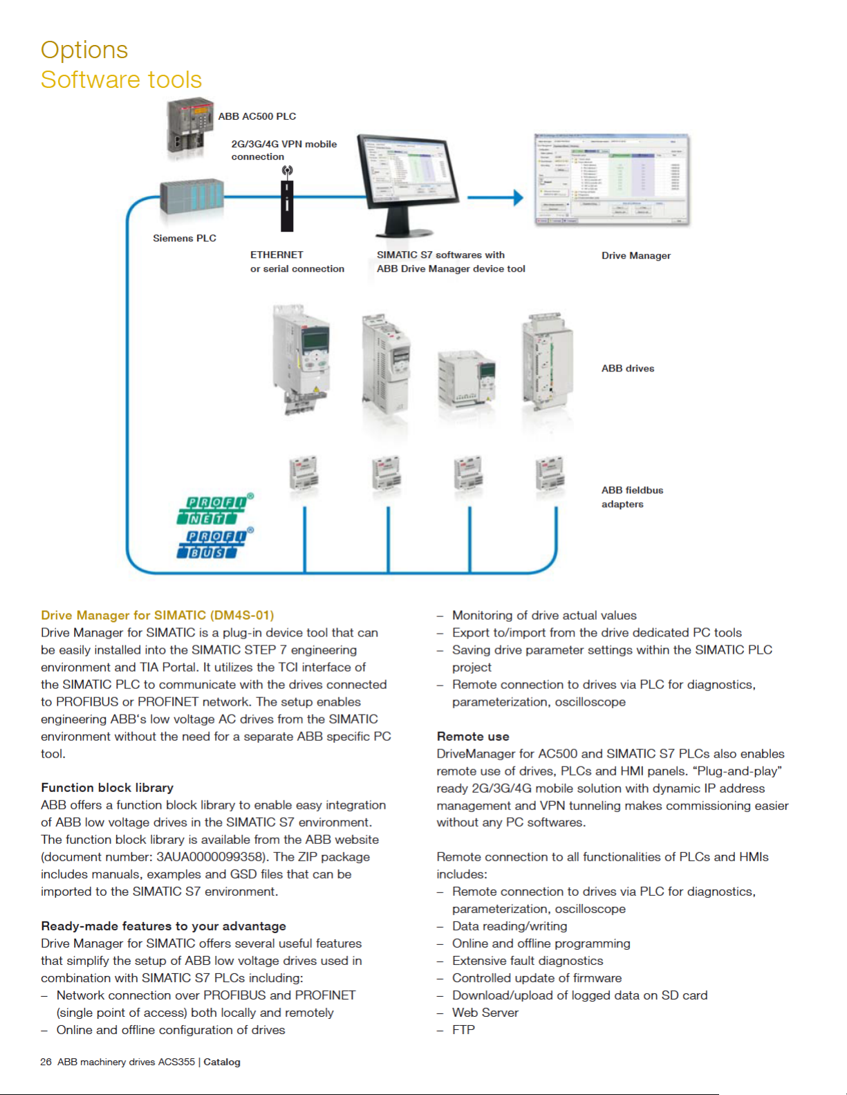
Drive Manager
Drive Manager offers machine builders and system integrators
a device tool to configure and monitor ABB’s low voltage
AC drives and AC500 PLCs. The software is included in the
Automation Builder engineering environment. Engineering
drives and PLCs in one environment simplifies work, and
saves commissioning time and cost.
Catalog | ABB machinery drives ACS355 25
Page 26
Page 27
Options
Software tools
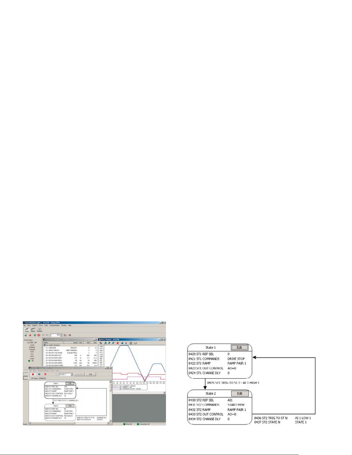
DriveWindow Light
DriveWindow Light is an easy-to-use commissioning and
maintenance tool for ACS355 drives. It can be used in an
offline mode, which enables parameter setting at the office
even before going to the actual site. The parameter browser
enables viewing, editing and saving of parameters. The
parameter comparison feature makes it possible to compare
parameter values between the drive and saved parameter
files. With the parameter subset you can create your own
parameter sets. Controlling of the drive is naturally one of the
features in DriveWindow Light. With this software tool, you
can monitor up to four signals simultaneously. This can be
done in both graphical and numerical format. Any signal can
be set to stop the monitoring from a predefined level.
Sequence programming tool
DriveWindow Light allows the user to visually build and
manipulate sequence programming parameters that are
loaded into the ACS355. The programming is done in a
graphical editor which displays each sequence step and its
transitions as an individual block.
Sequence programming enables application specific
programming with up to 8 configurable sequences. This
new and easy way to preset sequences reduces the need
for an external programmable logic control (PLC). In simple
applications an external PLC can be left out.
Startup wizards
Startup wizards make the setting of parameters easy. Simply
launch the wizard, select an appropriate assistant eg, for
setting analog outputs, and all parameters related to this
function are shown together with help pictures.
Highlights
– Graphical sequence programming tool for ACS355
– Editing, saving and downloading parameters
– Graphical and numerical signal monitoring
– Drive control
– Startup wizards
DriveWindow Light requirements
– Windows NT/2000/XP/Vista/7
– Free serial port from a PC
– Free control panel connector
Sequence programming example: radio button
In this example, analog input AI1 will start the motor at a fixed
speed. This function is useful when the drive is operated using
only a potentiometer. The motor speed is proportional to the
analog input when analog input level is higher than the fixed
level. In this case separate start and stop commands are not
needed.
The analog input level is monitored using the ACS355’s
supervision function. Supervision function status is set as
a transition rule between the two states of the sequence
program.
In state 1 the drive is in stand-by, monitoring the AI1 level.
In state 2 the drive starts in the forward direction and its
reference is from AI1. In state 2, the supervision function
monitors the AI1 level. If the value falls below the set limit, the
sequence program makes a transition to state 1 and the drive
is stopped.
There are two ramp pairs from which different ramping times
can be selected within each state. It is also possible within the
sequence program to control the analog output, digital output
and relay output independently.
Supervision function, AI1 scaling to speed reference, and ramp
times, can be set independent of the sequence program.
Catalog | ABB machinery drives ACS355 27
Page 28
Options
External
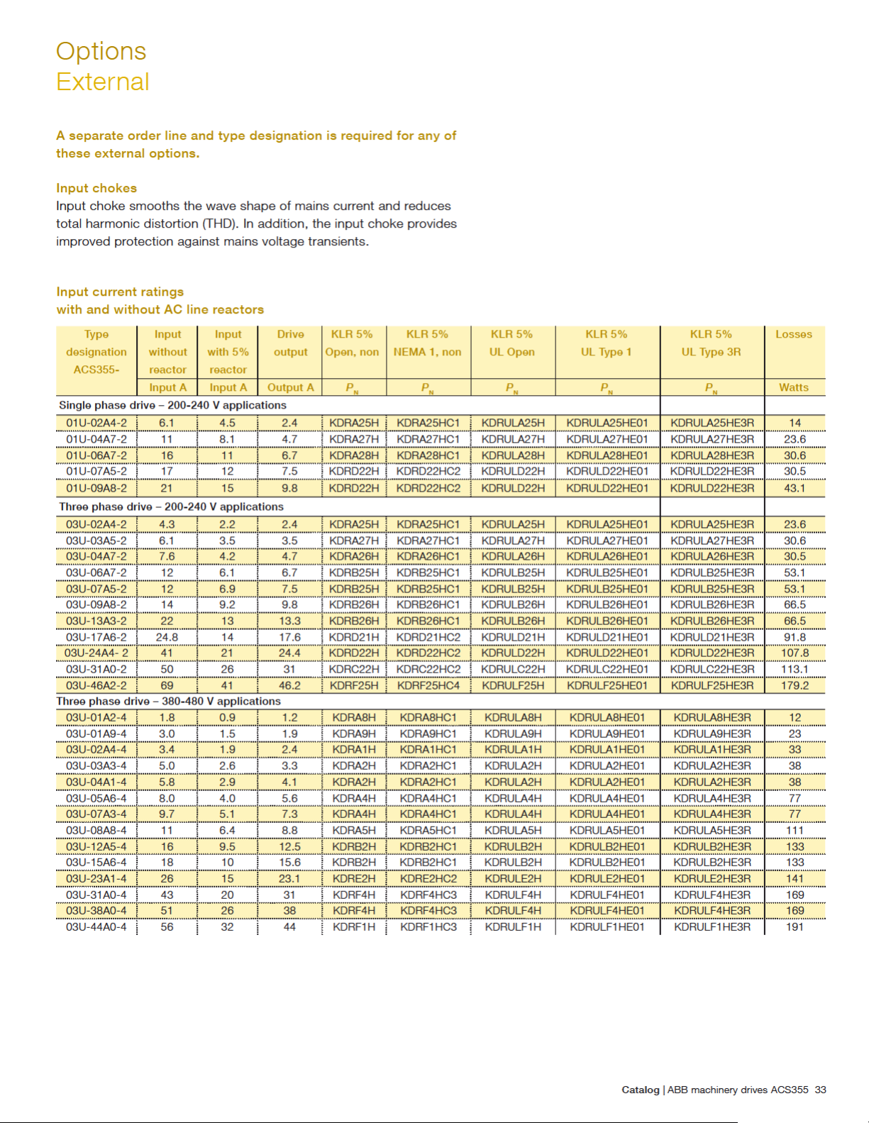
A separate order line and type designation is required for
any of these external options.
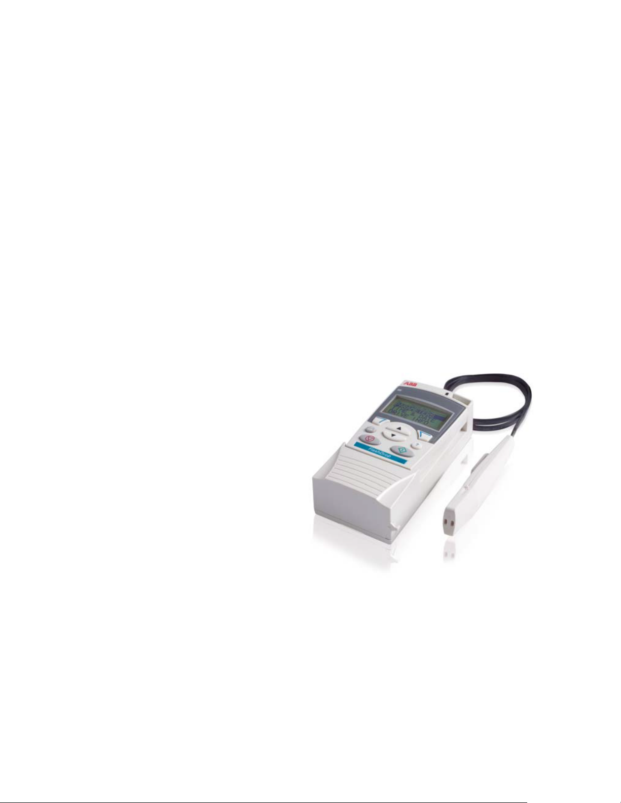
FlashDrop tool
FlashDrop is a powerful palm sized tool for fast and easy
parameter selecting and setting. It gives the possibility to
hide selected parameters to protect the machine. Only the
parameters needed in the application are shown. The tool can
copy parameters between two drives or between a PC and a
drive. All the above can be done without a power connection
to the drive – in fact, it is not even necessary to unpack the
drive.
DrivePM
DrivePM (drive parameter manager) is a tool to create, edit
and copy parameter sets for the FlashDrop tool. For each
parameter/group the user has a possibility to hide it, which
means that the drive user does not see the parameter/group
at all.
DrivePM requirements
– Windows 2000/XP/Vista/7
– Free serial port from a PC
FlashDrop package includes
– FlashDrop tool
– DrivePM software on a CD-ROM
– User’s manual in English and in pdf-format on the CD-ROM
– Cable OPCA-02 for connection between the PC and
FlashDrop tool
– Battery charger
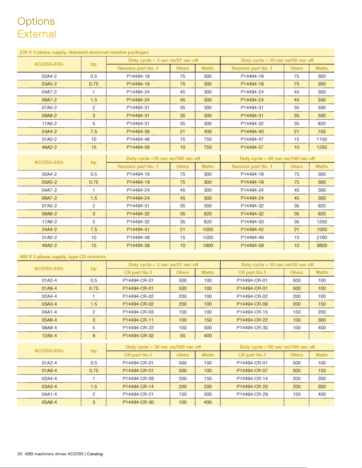
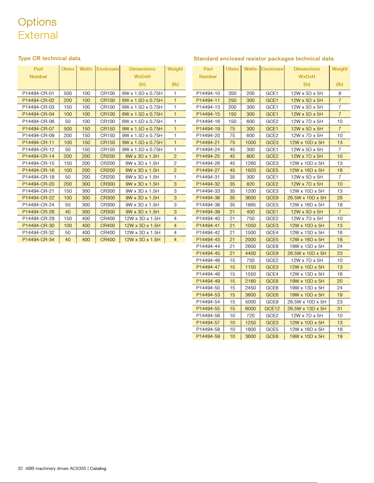
Brake resistors
ACS355 is delivered with an integrated brake chopper as
standard. Therefore no additional space or installation time is
needed. The brake resistor is selected using the table below.
For more information about the selection of brake resistors,
see the ACS355 user‘s manual.
28 ABB machinery drives ACS355 | Catalog
Page 29

Options
External
230 V 1 phase supply, type CR resistors
ACS355-01U- hp
02A4-2 0.5 P14494-CR-02 200 100 P14494-CR-02 200 100
04A7-2 1 P14494-CR-04 100 100 P14494-CR-04 100 100
06A7-2 1.5 P14494-CR-04 100 100 P14494-CR-11 100 150
07A5-2 2 P14494-CR-04 100 100 P14494-CR-16 100 200
09A8-2 3 P14494-CR-12 50 150 P14494-CR-24 50 300
Duty cycle = 3 sec on/27 sec off Duty cycle = 10 sec on/50 sec off
CR part No.1 Ohms Watts CR part No.1 Ohms Watts
ACS355-01U- hp
02A4-2 0.5 P14494-CR-02 200 100 P14494-CR-02 200 100
04A7-2 1 P14494-CR-11 100 150 P14494-CR-16 100 200
06A7-2 1.5 P14494-CR-16 100 200 P14494-CR-22 100 300
07A5-2 2 P14494-CR-22 100 300 P14494-CR-30 100 400
09A8-2 3 P14494-CR-32 50 400
230 V 1 phase supply, standard enclosed resistor packages
ACS355-01U- hp
02A4-2 0.5 P14494-19 75 300 P14494-19 75 300
04A7-2 1 P14494-24 45 300 P14494-24 45 300
06A7-2 1.5 P14494-24 45 300 P14494-24 45 300
07A5-2 2 P14494-31 35 300 P14494-31 35 300
09A8-2 3 P14494-31 35 300 P14494-31 35 300
ACS355-01U- hp
02A4-2 0.5 P14494-19 75 300 P14494-19 75 300
04A7-2 1 P14494-24 45 300 P14494-24 45 300
06A7-2 1.5 P14494-24 45 300 P14494-24 45 300
07A5-2 2 P14494-31 35 300 P14494-32 35 820
09A8-2 3 P14494-32 35 820 P14494-32 35 820
Duty cycle = 30 sec on/180 sec off Duty cycle = 60 sec on/180 sec off
CR part No.1 Ohms Watts CR part No.1 Ohms Watts
Duty cycle = 3 sec on/27 sec off Duty cycle = 10 sec on/50 sec off
Resistor part No. 1 Ohms Watts Resistor part No. 1 Ohms Watts
Duty cycle = 30 sec on/180 sec off Duty cycle = 60 sec on/180 sec off
Resistor part No. 1 Ohms Watts Resistor part No. 1 Ohms Watts
230 V 3 phase supply, type CR resistors
ACS355-03U- hp
02A4-2 0.5 P14494-CR-02 200 100 P14494-CR-02 200 100
03A5-2 0.75 P14494-CR-04 100 100 P14494-CR-04 100 100
04A7-2 1 P14494-CR-04 100 100 P14494-CR-04 100 100
06A7-2 1.5 P14494-CR-04 100 100 P14494-CR-11 100 150
07A5-2 2 P14494-CR-06 50 100 P14494-CR-18 50 200
09A8-2 3 P14494-CR-12 50 150 P14494-CR-24 50 300
17A6-2 5 P14494-CR-26 40 300 P14494-CR-34 40 400
ACS355-03U- hp
02A4-2 0.5 P14494-CR-02 200 100 P14494-CR-02 200 100
03A5-2 0.75 P14494-CR-04 100 100 P14494-CR-11 100 150
04A7-2 1 P14494-CR-11 100 150 P14494-CR-16 100 200
06A7-2 1.5 P14494-CR-16 100 200 P14494-CR-22 100 300
07A5-2 2 P14494-CR-24 50 300 P14494-CR-32 50 400
09A8-2 3 P14494-CR-32 50 400
Duty cycle = 3 sec on/27 sec off Duty cycle = 10 sec on/50 sec off
CR part No.1 Ohms Watts CR part No.1 Ohms Watts
Duty cycle = 30 sec on/180 sec off Duty cycle = 60 sec on/180 sec off
CR part No.1 Ohms Watts CR part No.1 Ohms Watts
Catalog | ABB machinery drives ACS355 29
Page 30
Page 31
Options
External
480 V 3 phase supply, standard enclosed resistor packages
ACS355-03U- hp
01A2-4 0.50 P14494-10 350 200 P14494-10 350 200
01A9-4 0.75 P14494-11 250 300 P14494-11 250 300
02A4-4 1 P14494-11 250 300 P14494-11 250 300
03A3-4 1.5 P14494-13 200 300 P14494-13 200 300
04A1-4 2 P14494-15 150 300 P14494-15 150 300
05A6-4 3 P14494-15 150 300 P14494-15 150 300
08A8-4 5 P14494-19 75 300 P14494-20 75 600
12A5-4 7.5 P14494-25 45 800 P14494-25 45 800
15A6-4 10 P14494-25 45 800 P14494-26 45 1260
23A1-4 15 P14494-32 35 820 P14494-33 35 1200
31A0-4 20 P14494-41 21 1050 P14494-43 21 2000
38A0-4 25 P14494-47 15 1150 P14494-49 15 2160
44A0-4 30 P14494-48 15 1550 P14494-50 15 2450
Duty cycle = 3 sec on/27 sec off Duty cycle = 10 sec on/50 sec off
Resistor part No. 1 Ohms Watts Resistor part No. Ohms Watts
ACS355-03U- hp
01A2-4 0.5 P14494-10 350 200 P14494-10 350 200
01A9-4 0.75 P14494-11 250 300 P14494-11 250 300
02A4-4 1 P14494-11 250 300 P14494-11 250 300
03A3-4 1.5 P14494-13 200 300 P14494-13 200 300
04A1-4 2 P14494-15 150 300 P14494-16 150 600
05A6-4 3 P14494-16 150 600 P14494-16 150 600
08A8-4 5 P14494-20 75 600 P14494-21 75 1000
12A5-4 7.5 P14494-26 45 1260 P14494-27 45 1920
15A6-4 10 P14494-26 45 1260 P14494-27 45 1920
23A1-4 15 P14494-38 35 1865 P14494-36 35 3600
31A0-4 20 P14494-44 21 2600 P14494-45 21 4400
38A0-4 25 P14494-53 15 3600 P14494-54 15 5000
44A0-4 30 P14494-53 15 3600 P14494-55 15 6000
All resistors are for stopping duty only.
Duty cycle = 30 sec on/180 sec off Duty cycle = 60 sec on/180 sec off
Resistor part No. 1 Ohms Watts Resistor part No. 1 Ohms Watts
Catalog | ABB machinery drives ACS355 31
Page 32
Page 33
Page 34
Page 35
Options
External
A separate order line and type designation is required for
any of these external options.
EMC filters
The ACS355’s internal EMC filter is designed to meet category
C3 requirements of EN/IEC 61800-3 standard. External
EMC filters are used to enhance the drives electromagnetic
performance in conjunction with its internal filtering. Maximum
motor cable length depends on required electromagnetic
performance, according to the table below.
Type
designation
ACS355-
Frame
size
Filter
type
with external EMC
Cable length
filter
1)
Cable length
without external
EMC filter
C1
[m]C2[m]C3[m]C3[m]
1-phase AC supply, 200 to 240 V
01X-02A4-2 R0 RFI-11 10 30 - 30 30
01X-04A7-2 R1 RFI-12 10 30 50 30 50
01X-06A7-2 R1 RFI-12 10 30 50 30 50
01X-07A5-2 R2 RFI-13 10 30 50 30 50
01X-09A8-2 R2 RFI-13 10 30 50 30 50
3-phase AC supply, 200 to 240 V
03X-02A4-2 R0
03X-03A5-2 R0
03X-04A7-2 R1
03X-06A7-2 R1
03X-07A5-2 R1
03X-09A8-2 R2
RFI-32
RFI-32
RFI-32
RFI-32
RFI-32
RFI-32
2)
10 30 - 30 30
2)
10 30 - 30 30
2)
10 30 50 30 50
2)
10 30 50 30 50
2)
10 30 50 30 50
2)
10 30 50 30 50
03X-13A3-2 R2 RFI-33 10 30 50 30 50
03X-17A6-2 R2 RFI-33 10 30 50 30 50
03X-24A4-2 R3 RFI-34 10 30 50 30 50
03X-31A0-2 R4 RFI-34 10 30 50 30 50
03X-46A2-2 R4 RFI-34 10 30 50 30 50
3-phase AC supply, 380 to 480 V
2)
03X-01A2-4 R0
03X-01A9-4 R0
03X-02A4-4 R1
03X-03A3-4 R1
03X-04A1-4 R1
03X-05A6-4 R1
03X-07A3-4 R1
03X-08A8-4 R1
RFI-32
RFI-32
RFI-32
RFI-32
RFI-32
RFI-32
RFI-32
RFI-32
30 30 - 30 30
2)
30 30 - 30 30
2)
50 50 50 30 50
2)
50 50 50 30 50
2)
50 50 50 30 50
2)
50 50 50 30 50
2)
50 50 50 30 50
2)
50 50 50 30 50
03X-12A5-4 R3 RFI-33 40 40 40 30 50
03X-15A6-4 R3 RFI-33 40 40 40 30 50
03X-23A1-4 R3 RFI-33 40 40 40 30 50
03X-31A0-4 R4 RFI-34 - 30 - 30 50
03X-38A0-4 R4 RFI-34 - 30 - 30 50
03X-44A0-4 R4 RFI-34 - 30 - 30 50
1)
C4
[m]
Low leakage current filters
Low leakage current filters are ideal for installations where
residual current devices (RCD) are required and leakage
current needs to be below 30 mA.
Type
designation
Frame
size
ACS355-
Low leakage current filters, 3-phase AC supply, 400 V
03X-01A2-4 R0 LRFI-31 10
03X-01A9-4 R0 LRFI-31 10
03X-02A4-4 R1 LRFI-31 10
03X-03A3-4 R1 LRFI-31 10
03X-04A1-4 R1 LRFI-31 10
03X-05A6-4 R1 LRFI-31 10
03X-07A3-4 R1 LRFI-32 10
03X-08A8-4 R1 LRFI-32 10
1)
Internal EMC filter must be disconnected by removing the EMC screw from
the drive. RFI-11, RFI-12 and RFI-13 are also low leakage current filters.
EMC standards in general
EN 61800-3
(2004),
product
standard
EN 55011, product
family standard for
industrial, scientific
and medical (ISM)
Category C1 Group 1
Category C2 Group 1
Category C3 Group 2
Category C4 Not applicable 2
Filter type Cable length
EN 61800-3/A11 (2000),
product standard
equipment
st
1
environment, unrestricted
Class B
st
environment, restricted
1
Class A
2nd environment, unrestricted
Class A
nd
environment, restricted
with LRFI filter
C2
[m]
distribution
distribution
distribution
distribution
1)
1)
Internal EMC filter must be connected with the EMC screw in the drive.
When the filter is not connected the C4 maximum cable lengths are allowed
to be used.
2)
RFI-30 also available as footprint filter for frame size R0 and R1 with similar
characteristics.
Catalog | ABB machinery drives ACS355 35
Page 36
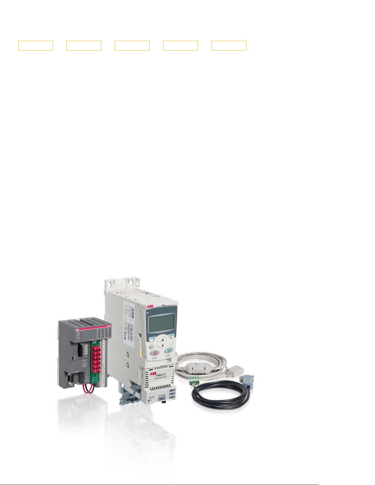
Compact PLC and AC drive starter kit
ACS355 - 01E - 02A4 - 2 + P924
ABB’s programmable logic controller (PLC) and AC drive starter
kit offer an out-of-box motor control in minutes.
The compact, yet powerful kit, targets small-scale machines
and systems requiring PLC control and up to seven drives.
Easy ordering and fast startup
Providing PLC, AC drive and accessories as a package
simplifies ordering and provides quick deliveries. The ordering
code for the starter kit is ACS355-01E-02A4-2+P924.
The starter kit for evaluation and customization (application
programming) includes:
– PLC AC500-eCo PM554-T (8 DI / 8 DO-Transistor)
– ACS355-01E-02A4-2 (single phase 230 V AC, with power of
0.37 kW) drive with ACS-CP-A assistant control panel and
FMBA-01 Modbus fieldbus adapter
– MC502 SD card containing the AC500 function block library
for drives with complete functional objects for easy and
secure programming
– Several accessories such as MC503 SD card adapter,
TA562-RS serial interface, TA571-SIM 6 switches simulator,
TK503 communication cable between the PLC and the drive
for programming
– Full version of PS501 Control Builder programming
environment with all functionalities. Excludes sheet license to
receive free software updates.
– A step-by-step guide for setting up the intuitive set
Ready-made reorder packages for ACS355 enables expansion
of starter kit to a multiple drives system. AC500 product family
offers several controllers for system scaling.
Benefits of the kit
– Control of a motor in minutes
– Easy ordering of PLC, AC drive and accessories as a kit from
ABB’s central stock
– Entry-level kit for learning the Control Builder programming
environment based on IEC 61161-3 programming standard
– Pre-engineered communication libraries for all ABB LV AC
drives
– Ready-made HMI visualization
– Cost-efficient system expansion, since the same application
program can be used for the entire AC500 PLC platform
36 ABB machinery drives ACS355 | Catalog
Page 37
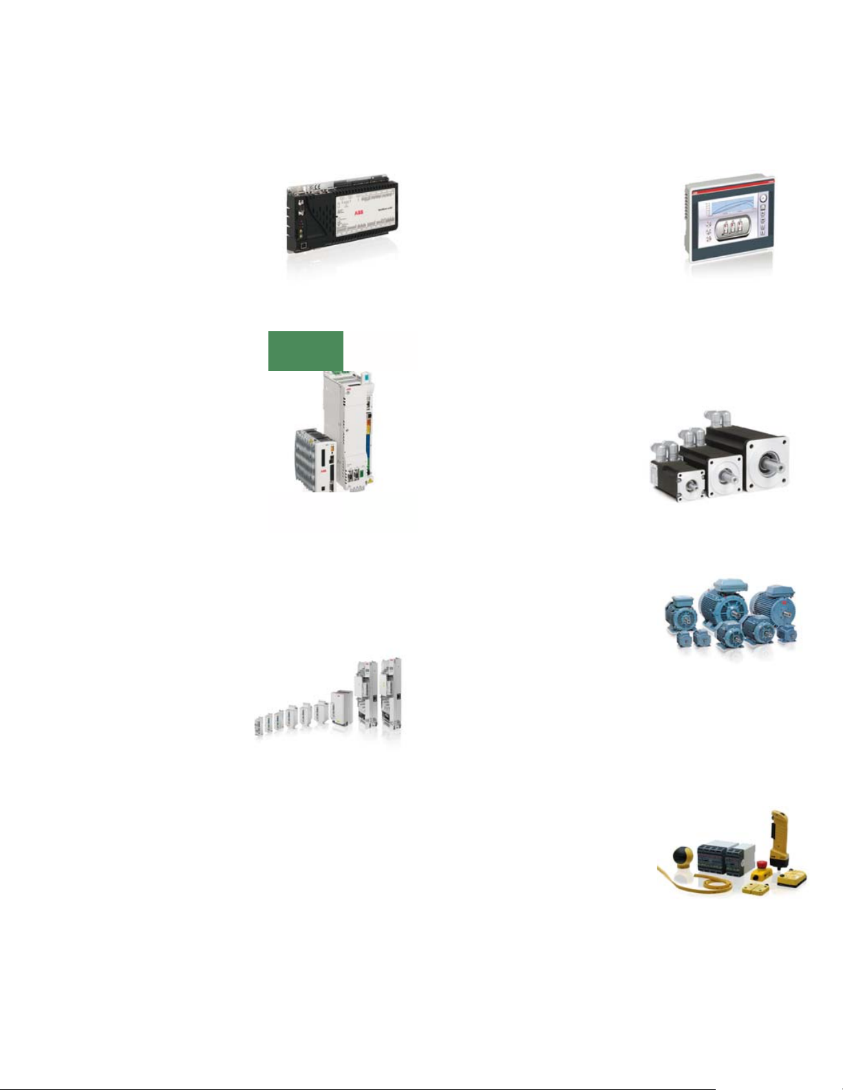
ABB automation products
Motion controllers
ABB offers a wide range of motion
control products to suit many different
applications. Motion controllers are
available in PCI format, as stand-alone
units with USB, CANopen®, serial and
Ethernet interfaces and as intelligent
programmable drives for use in single
or multiaxis systems.
Servo drives
ABB offers a range of servo drives to
cover many different applications. Its
drives range from simple analog,
fieldbus controlled drives, indexing
drives, fully programmable motion drives
and real-time Ethernet solutions based
on the open standard Ethernet
PowerLink and EtherCAT
drives control rotary and linear AC servo
motors, and are available from 1 A
single phase through to 65 A three
phase.
Machinery drives
ABB offers machinery builders AC drives
from component drives up to high
performance machinery drives.
Global support and service
guarantees lifelong satisfaction.
ABB machinery drives provide speed
control of diverse applications from spa
bath motors to treadmill motors, as well
as high precision applications such as
positioning and synchronization
systems.
®
. ABB motion
Control panels
Our control panels offer a wide range
of touchscreen graphical displays from
3.5” up to 15”. They are provided with
user-friendly configuration software
that enables tailor-made customized
HMI solutions. Rich sets of graphical
symbols and the relevant drivers for
ABB automation products are provided.
Control panels for visualization of AC500
web server applications are available.
Servo motors
ABB’s BSM series servo motors offer a
wide choice of high or low inertia
models with winding options, feedback
devices and gearheads to match. All
ABB servo motors are designed for
durability and ability to handle harsh
environments.
AC motors
ABB’s low voltage AC motors are
designed to save energy, reduce
operating costs and enable demanding
motor applications to perform reliably
and without unscheduled downtime.
General performance motors combine
convenience and easy handling
seamlessly with ABB’s engineering
expertise. Process performance motors
provide the most comprehensive,
versatile set of motors for the process
industries and heavy-duty applications.
Jokab safety products
ABB Jokab Safety offers an extensive
range of innovative products and
solutions for machine safety systems.
It is represented in standardization
organisations for machine safety and
works daily with the practical application
of safety requirements in combination
with production requirements. ABB
Jokab Safety delivers everything from a
single safety solution to complete safety
systems for single machines or entire
production lines.
Catalog | ABB machinery drives ACS355 37
Page 38
Page 39

Life cycle services
Your choice, your future
Your future takes the course of the service you choose
for your drives.
Whatever your choice, it should be a well-informed
decision. No guesswork. We have the expertise and
experience to help you find and implement the right
service for your drive equipment.
You can start by asking yourself these two critical
questions:
– How do I want to maintain my drives?
– What would my optimal service options be?
Your choice, your business efficiency
ABB Drive Care agreement lets you focus on your core
business. A selection of predefined service options matching
your needs provides optimal, more reliable performance,
extended drive lifetime and improved cost control. So you can
reduce the risk of unplanned downtime and find it easier to
budget for maintenance.
Service offerings for your business
Your needs in service usually depend on your operation, priorities, and life cycle phase of your equipment. Here are the
most typical service needs with some of our service product options that satisfy them:
Is performance most critical to your
operation?
Get optimal performance out of your
machinery and systems.
Supporting services include:
− Training
− Inspections and Diagnostics
− Hardware and Control Upgrades
− Retrofits
− Workshop Repair
Is uptime your priority?
Keep your drives running with precisely
planned and executed maintenance.
Supporting services include:
− Life Cycle Assessment
− Installation and Commissioning
− Spare Parts
− Preventive Maintenance
− Reconditioning
Need to extend your assets’ lifetime?
Maximize your drive’s lifetime with our
services.
Supporting services include:
− Life Cycle Assessment
− Hardware and Control Upgrades
− Retrofits
− Replacement, Disposal and Recycling
Is rapid response a key consideration?
If your drives r
our global network is at your service.
Supporting services include:
− Technical Support
− Drive Exchange
− On-site repairs
− Remote Support
equire immediate action,
Catalog | ABB machinery drives ACS355 39
Page 40

40 ABB machinery drives ACS355 | Catalog
Page 41

Notes
Catalog | ABB machinery drives ACS355 41
Page 42

Notes
42 ABB machinery drives ACS355 | Catalog
Page 43

Notes
Catalog | ABB machinery drives ACS355 43
Page 44

Contact us
© Copyright 2015 ABB. All rights reserved.
Specifi cations subject to change without notice.
3AUA0000081917 REV G US 18.5.2015
 Loading...