

Page 1

A2ASIMULATIONS
COMANCHE
www.a2asimulations.com COMANCHE 250 MANUAL
FOR SIM ULATIO N USE ONLY
ACCU-SIM COMANCHE 250
:::
A2ASIMULATIONS
1
Page 2

ACCU-SIM COMANCHE 250
© 2015 A2A Simulations Inc. All rights reserved.
Published by A2A Simulations Inc.
ATTENTION!
Accu-Sim Comanche 250, including sounds, aircra, and all content
is under strict, and enforceable copyright law. If you suspect anyone has pirated any part of Accu-Sim Comanche 250, please contact
piracy@a2asimulations.com
RISKS & SIDE EFFECTS
Ergonomic Advice
▶ Always maintain a distance of at least 45cm to
the screen to avoid straining your eyes.
▶ Sit upright and adjust the height of your chair so that
your legs are at a right angle. The angle between your upper and forearm should be larger than 90º.
▶ The top edge of your screen should be at eye level or be-
low, and the monitor should be tilted slightly backwards, to prevent strains to your cervical spine.
▶ Reduce your screen’s brightness to lower the con-
trast and use a flicker-free, low-radiation monitor.
▶ Make sure the room you play in is well lit.
▶ Avoid playing when tired or worn out and take
a break (every hour), even if it’s hard…
Epilepsy Warning
Some people experience epileptic seizures when viewing flashing lights or
patterns in our daily environment. Consult your doctor before playing computer games if you, or someone of your family, have an epileptic condition.
Immediately stop the game, should you experience any of the following
symptoms during play: dizziness, altered vision, eye or muscle twitching,
mental confusion, loss of awareness of your surroundings, involuntary
movements and/or convulsions.
Page 3

A2ASIMULATIONS
COMANCHE
ACCU-SIM
COMANCHE 250
Page 4

Page 5

CONTENTS
6
30
32
34
38
42
48
52
54
DYNAMIC ELEGANCE
DEVELOPER’S NOTES
FEATURES
QUICK-START GUIDE
ACCU-SIM AND THE COMANCHE 250
ACCU-SIM AND THE
COMBUSTION ENGINE
PROPELLERS
GENERAL
LIMITATIONS
62
70
74
84
88
92
100
PERFORMANCE
WEIGHT AND BALANCE
AIRPLANE & SYSTEM
DESCRIPTIONS
EMERGENCY PROCEDURES
EMERGENCY PROCEDURES
EXPLAINED
AIRPLANE HANDLING,
SERVICE & MAINTENANCE
CREDITS
56
NORMAL PROCEDURES
Page 6

DYNAMIC ELEGANCE
Mitchell Glicksman
6
A2ASIMULATIONS
:::
COMANCHE 250 MANUAL www.a2asimulations.comFOR SIM ULATIO N USE ONLY
Page 7

O AIRPLANE PERSONIFIES THE EPITHET
“Dynamic Elegance” more aptly than does
N
the Piper Comanche 250.
The unique conjoining of many
superlative aeronautic and aesthetic
qualities marks this very special aeroplane. It has been said that if an aeroplane looks right, it will fly right. In this
it is supposed that the eye’s natural
ability to sense the pleasing proportion
and intrinsic eiciency of a design is a
reliable predictor of similarly excellent
aeronautic performance. The Comanche
250 proves that this adage may be relied
upon and bears validity. The Piper
Comanche takes its well-deserved place
on an illustrious list of aeroplanes which
are both so very pleasing to the eyes and
which are equally capable of superior
performance.
There are many including this writer
who hold that the Comanche is among
the most beautiful of all General Aviation
(GA) aircra, if not the most beautiful.
From any angle the Comanche treats the
eyes. This is what provides its elegance.
Its superlative performance is a matter
of record and this provides its dynamism. These two great and rare qualities, beauty and performance would be
enough in and of themselves to place the
Comanche at the pinnacle of GA aircra,
but the Comanche possesses an additional quality, one which, aer all, may
be its most endearing.
Of all of the high performance GA aircra the Comanche is arguably the least
demanding of the relatively low- time
pilot. That this is so is not an accident
or a fortuitous circumstance -- William
Piper specifically intended that it should
be so. The Comanche’s forgiving flight
characteristics and its refusal to turn and
bite an unwary pilot without plenty of
warning, its relatively gentle stall, easy
handling at low airspeeds and its overall
delightful handling at all airspeeds are
confidence boosters for its fortunate
pilots.
The Comanche is also particularly
exceptional in that it does not achieve
its excellent aerodynamic performance
at the expense of interior room and
comfort; it is among the roomiest and
most comfortable of “high performance”
aeroplanes. Neither does the Comanche
sacrifice useful load nor its generous
weight and balance envelope at the altar
of high airspeed. It is a highly capable
heavy load hauler and its capacious
useful load as well as its ability to safely
carry baggage and substantial rear seat
passengers without straining its a load
limits is far better than its closest competitors of equal horsepower -- including and specifically the V-tail Beechcra
Bonanza. Perhaps most importantly, the
Comanche does not achieve its performance by the intrinsic design features
which compromise stable flying characteristics. Its light airframe weight and its
generous, high aspect-ratio, laminar flow
wing provides the Comanche with high
eiciency as well as a low wing loading.
Accordingly, Comanche pilots and
owners are particularly loyal and satisfied, and for good reason; the Comanche
delivers extraordinarily dynamic performance while embodying the highest
degree of aeronautic elegance.
So, how is it that all of these superlative qualities came together in this aeroplane? Well, therein lays the Comanche’s
tale, one redolent of aeronautic expertise, prescience, confidence and also of
a fierce competitive spirit. As it happens,
it all began a little more than ten years
before the first Comanche ever flew.
Once upon a time…
www.a2asimulations.com COMANCHE 250 MANUAL
FOR SIM ULATIO N USE ONLY
:::
A2ASIMULATIONS
7
Page 8

DYNAMIC ELEGANCE
THE MODERN AGE OF
THE PRIVATE AIRPLANE
BEGINS — ENTER THE
BEECHCRAFT BONANZA
Summer, 1945 -- While the world is joyously celebrating the Allied victory in
Europe, World War II is still savagely raging
in the Pacific. The United States’ combined
armed services along with those of its
valiant Allies are pressing forward, island
by terrible island at horrific human cost,
drawing an ever- tightening noose around
the neck of the Imperial Empire of Japan.
As the final victory and a new era of peace
looms nearer and nearer the American
General Aviation (GA) industry made up
of companies such as Piper, Cessna, Ryan,
Stinson, Luscombe and Beechcra is
already making plans for what they expect
and fervently hope will come aer the
War is finally over. Unfortunately or perhaps inevitably, expectations, which are
so oen fragile and which are ultimately
as insubstantial as vapour are also as precious as dreams; and like dreams expectations are oen rendered irrelevant and are
ultimately crushed by brutish reality. Aer
almost four years of stifling limitations
incurred by the unavailability of raw materials, machinery and workers, all of which
and whom went into the War eort, the
GA industry had become, or perhaps more
accurately had succumbed to becoming
manufacturers of solely that which the War
Department required and demanded.
Thus, those American GA companies
who persevered performed their needed
part as highly regulated cost-plus cogs in
the War’s wheels, first under the WPB (War
Production Board) and then under the
OWM (Oice of War Mobilisation), subject
as well to the rules and regulations of the
OPA (Oice of Price Administration) and
the WMC (War Manpower Commission).
Piper, for instance, just as it was beginning to achieve the blessings of it’s longworked- for financial success in the late
1930’s was compelled in 1941 to convert
its popular J-3 Cub into a military scout,
an artillery spotter, a short- field, short
distance transport vehicle for a pilot and
a single V. I. P., and for a (mercifully) short
while, amazingly, a motorless three-place
glider trainer. Cessna turned out the AT-17
“Bamboo Bomber”, a multi-engine trainer,
the AT-17, etc., Beechcra built the AT-7
Navigator/C-45/UC-45/CT-128 Expeditor
From its inception
the Bonanza was
intended to largely
appeal to the
corporate/business
community as we
see here. However,
in this one we also
see a little of the
Western, “Camp
out with your
Bonanza” outdoor
flavour which was
another intended
part of the appeal
that Beechcraft
wanted to make.
There would be a
lot more of this kind
of appe al in ads to
come and all of this
coming long before
the television show
of the same name.
The main picture is
interesting. These
men must have
been as small as
elves to have that
much head and
shoulder room in
the Bonanza’s cabin.
Also, those guys in
the back had better
have been very slim
and lightweight,
the V-tail Bonanza
cannot take much
of an af t load.
versions of its sturdy and thoroughly excellent twin-engine Model 18, and so on with
regard to all within the GA industry.
The irony of it was that for all of the
splendid work and muscular energy spent
producing aircra for the war eort, none
of these very mission- specific wartime
airplanes were designed for or expected to
ever be made available to the public at any
future time. And so, while a small profit
(very small to be sure) was earned from
their military manufacturing eorts, the
commercial aspects of GA manufacturers,
at least for the duration of the War, came to
a complete halt.
This is not to say that Piper and the
other GA manufacturers did not sincerely
desire to do their part in helping to win the
war. Their oicers and employees were as
patriotic as the best Americans and their
strenuous eorts substantially enabled
the inevitable victory. That being said, as
the War progressed they patiently waited
and anxiously looked forward to the postwar era wherein they might finally reap the
sweet commercial rewards of their recent
sacrifices by selling great shiploads of civilian airplanes to hoards of distinctly aviation- friendly and flight- familiar ex-service
pilots.
In the summer of 1945, as the War
wound down to its end, the owners, CEOs
and Boards of American General Aviation
manufacturers expected, or if you prefer,
dreamed that their anxiously anticipated
heighday was truly nigh. Aer all, they
reasoned (with a heavy dose of wishful
thinking) that when all of those young
aviators come home aer having experi
enced the joy and freedom of flying, they
would surely wish to continue in a simi
lar vein and become owners and pilots
of their own airplanes. They further rea
soned that when these young men (and
some young women as well) having been
released from the armed services sal
lied forth en masse, clamouring for airplanes to buy, the American GA Industry
would be right there, blithely and heartily
ready, cheerfully awaiting their chance
-
-
-
-
8
A2ASIMULATIONS
:::
COMANCHE 250 MANUAL www.a2asimulations.com
FOR SIM ULATIO N USE ONLY
Page 9

Notice the slow-moving automobile traffic
below over which the sleek, sparkling
silver Bonanza effortlessly travels.
More “C ampout with your Bonanza”. Business
and pleasure combined — irresistible appeal.
Pure business appeal. Note the oil rig pictured.
The upscale and super- expensive Bonanza was
strongly pitched to the burgeoning oil business.
to supply the anxious needs and desires
of these valiant and victorious aerial vet
erans. In any event, it sounded right and
no one apparently thought that there was
any flaw in that analysis and expectation.
One aircra manufacturer however,
Beechcra, did more than merely dream.
With the surrender of the Empire of Japan
on September 2, 1945 which marked the
end of W.W. II, the world commenced to dig
itself out of mountains of ruin and rubble,
account for and mourn numberless victims, and as soon as might be possible to
get on with life in the bright and promising era of Peace. In the United States that
which had been interrupted by the war was
now busy re-commencing. GA manufacturers were now free to produce aeroplanes
for the public with an unlimited supply of
necessary materials and workers.
While virtually all of the other GA manufacturers planned on oering pretty much
the same aircra or types of aircra that
they has built in the pre-war 30’s; Piper
oering the J-3 “Cub”, Cessna oering a
distinctly pre-war style aeroplane, the 5
seat C-190/195 as well as the two-place,
tailwheel equipped C-120, Taylorcra,
Aeronca, Stinson and Luscombe all once
again oering their pre-war designs;
Beechcra had another idea, a new idea.
Beechcra was bent upon producing
a brand- new aeroplane, something not
only entirely dierent from anything that
they had previously built, but something
new and exciting that had not yet been
seen in the GA world. This was the seminal
Bonanza Model 35 which was to become
the airplane that sparked and kick-started
post-war modern General Aviation.
Remarkably prescient in every way,
Beechcra well-named the new aeroplane, “Bonanza”. Even before Beechcra
had actually sold a single aeroplane, it
was already a remarkable economic success. Shortly aer its grand introduction
to the public by way of press releases and
magazine advertisements, corporations,
businesses and wealthy professionals
placed almost 1,500 orders in advance of
its release with thousands more orders
soon to come. Without any question the
Bonanza was an unqualified and immediate roaring success.
In 1947 Beechcra embarked upon a
very powerful and sweeping advertising
campaign to debut and introduce to the
public what it was confident would create
a sea-change in GA aviation. Beechcra
was right on all counts.
Let’s take a close look at a variety of
advertisements that illustrate the new
market Beechcra expected to serve with
the Bonanza. Here are some early (1947)
ads which were part of the campaign to
introduce the Bonanza to the public:
BEECHCRAFT’S BIG IDEA
Designed by Ralph Harmon and his associates in 1945 as the war was coming to an
end, the Model 35 Bonanza had its first test
flight on December 22, 1945. Incorporating
all of what was then known about aerodynamics, aircra structure and aviation
technology, the Bonanza’s clean, stressed
skin (monocoque) all-metal structure
was reminiscent of the recently lionised
Spitfires and Mustangs and in virtually
every way was a distinct departure from
previous mostly fabric covered, fixedundercarriage, tailwheel GA aircra.
The first Bonanza, the Model 35, had a
retractable tricycle undercarriage, a distinctive V-tail which was unique for GA
aircra and had seats for four adults. The
first Bonanzas were originally equipped
with an interesting and curious laminated
wood, electrically controlled, pilot adjustable, fixed pitch propeller. This was not an
automatic constant speed propeller which
was a common item even by 1945, but was
a variable pitch unit electrically adjustable
by the pilot to meet power requirements.
Some early Bonanzas that are still flying
still have this kind of propeller; however,
most of these propellers have been converted to metal blades.
The Model 35 was powered by a simple
to manage and inexpensive to run sixcylinder, horizontally opposed, air cooled
www.a2asimulations.com COMANCHE 250 MANUAL
FOR SIM ULATIO N USE ONLY
:::
A2ASIMULATIONS
9
Page 10

DYNAMIC ELEGANCE
165 hp Continental E-165 engine (O-470
family). High performance GA aircra,
including Beechcra’s, had traditionally
been powered by large 7 or 9 cylinder,
round radial engines which were thirsty
of fuel and oil. A moderate sized, horizontally opposed engine in the Bonanza was
a breath of fresh air which engendered the
colour of progressive modernism while
promising low fuel and oil consumption
and a much quieter cabin.
Unsurprisingly, the Bonanza spectacularly burst onto the GA market and was
undisputedly and justly acclaimed by all to
be the first of a new breed of GA aircra.
In 1945 at the time that the Bonanza
was being conceptualised, what late in the
following decade would become a new GA
culture largely populated by casual weekend aviation hobbyists who were primarily relatively low-time VFR-only pilots and
who flew in order to take their friends and
families alo for pleasant, good-weather
aerial jaunts and vacations and to consume that $100 hamburger in a restaurant
at some distant airport, did not yet exist,
nor could it then have then been foreseen.
Accordingly, in 1945 Beechcra’s design
philosophy and the targeted market for
the Bonanza was, as we shall see, in no
way aimed at the part-time aviation aficionados to come, but at an entirely different group of highly experienced pilots
who it was expected would own and/or be
hired to fly Bonanzas for businesses and
corporations.
Beechcra’s goal and expectations
for the Bonanza were clear: To create the
fastest aeroplane for its horsepower that
could carry up to four in relative comfort
which would be primarily purchased by
prosperous individuals, corporations and
businesses to be used as a luxury executive transport flown by experienced, exmilitary service pilots.
Yes, all during the war most Americans
hoped for, waited for, and expected that
peace would bring forth a brave and
prosperous New World, a World which
in August, 1945 had finally arrived.
Beechcra’s particularly clear prescience
was that this New World’s skies would
be greatly populated with aircra of all
shapes and sizes in general and with its
new, game changing Bonanza in particular.
As said, Beechcra’s plan included
the idea that those who would mostly be
flying the Bonanza would be primarily
those valiant young ex-Army, Navy and
Marine Corps aeroplane drivers who had
of late been regularly flying and fighting
at 40,000’ and at up to 400 MPH +. Many
of these soon- to- be Bonanza pilots had
regularly flown massive, heavy, fourengine aircra on perilous high-altitude,
long-range missions over Europe, East
Asia and throughout the Pacific Theatre.
It was assumed that they would not likely
regard flying the neat and trim little fourseat Bonanza with its 165 h.p. engine to be
much of a challenge. These were the pilots
whom Beechcra expected would be filling the rolls of those who would be flying
corporate V.I.P. s, business oicers and representatives to and from board and sales
meetings all over the country in post-war
peacetime America. Beechcra’s mission
was to see that as many of them as possible would be flying Bonanzas.
Beechcra’s vision turned out to be
at least partly true as it was primarily extransport and bomber pilots who filled
out applications with businesses and corporations of all kinds to become aerial
chaueurs. Apparently most of the fighter
pilots had had more than their fill of what
was, from their perspective, the “joy” and
“thrill” of flying.
What this meant regarding the design of
the Bonanza was that Beechcra properly
understood that these ex-military pilots
would need no coddling when it came
to providing an aeroplane suitable for
them to fly. Accordingly, taking extra care
to design the Bonanza to be a gentle and
easy handing aeroplane for a multitude of
casual, weekend, sportsman pilots did not
appear to be any part of Beechcra’s intent
or concern. It seemed that a clean design
was paramount, which could be sold most
readily, i.e. performance -- high speed, fast
climb, long range, eiciency, comfort, as
well as owner’s prestige and a kind of modern-world cool sexiness -- everything that
makes an aeroplane exciting and satisfying
to behold and to fly.
Not surprisingly the Bonanza’s fastgrowing reputation as the “best”, and
“most modern” private aeroplane
attracted a great many wealthy and wellhealed professionals and “sportsmen”,
many of whom had no more than perhaps
a few hundred hours flight time, if that
much, and who were largely of limited
aeronautic experience. They were used
to possessing whatever they wished and
could easily aord the newest of the new
and the best of the best. Not accidentally
Beechcra had placed Bonanza squarely in
that class of possessions; but therein was
the rub.
All aeroplanes are subject to that most
basic law of physics: where one thing
is gained, another must be diminished.
Accordingly, the design of all aeroplanes
necessitates many compromises. For
instance, maximum airspeed and performance for available power is generally
and most readily obtained at the expense
of various other flight characteristics that
would, say, make the aeroplane suitable
as a casual touring aeroplane, and vice
versa. Compromises in design must be
made favouring that which the manufacturer sees as its goal for any particular aeroplane. To achieve specific design
goals such as high airspeed, comfortable
cabin space, long range, heavy load carrying, gentle handling, moderate runway
requirements, etc. designers make choices
regarding an aircra’s dimensions, geometry, proportion, materials, weight, airfoils,
thicknesses, shapes, wing and power loading, etc. In creating a design which would
extract maximum airspeed from available
power, the Bonanza’s designers clearly
made specific choices and compromises,
many of which did not favour the low-time
pilot.
Aer a tragic V-tail separation during
early flight testing in 1946 which caused
the death of the test pilot and extensive
re-design and re-testing of the tail surfaces
(but not to a suicient degree as we shall
see), the existing problems seemed to be
cured and all went well. By the end of 1947
the first gleaming silver Bonanzas rolled
o the assembly lines. In its class and for
its time it was the epitome of GA aeronautical design and engineering -- fast,
beautiful and looking like nothing that
had come before. Sure, it was pricey at the
then great sum of $7,975.00 ($84,613.32 in
2015), however a 2015 Bonanza G36 costs
approximately $691,390 depending upon
installed electronics, equipment, etc.),
but to its well-healed purchasers price
was no object. In fact, the Bonanza’s high
price guaranteed exclusivity and granted
its owner distinct prestige and pride of
ownership.
10
A2ASIMULATIONS
:::
COMANCHE 250 MANUAL www.a2asimulations.com
FOR SIM ULATIO N USE ONLY
Page 11

The would-be fighter pilot ’s dream, the Cavalier Mustang appe ars
here in civilian pain t. Many were finished in “military” colours and
some wi th authentic camouflage and markings. While surely an
exciting prospective mount for any pilot, the Cavalier required long and
extensive training and was expensive to both purchase and to maintain.
It wasn’t for everyone and was not produced in large numbers.
The Bonanza early safety record might
have been bet ter if more of these pilots
entered general aviation after the war.
Upon the pre-production introduction of the Bonanza through an extensive advertising campaign (see above)
more than 1,400 paid pre-orders for the
aeroplane flowed into Beechcra’s sales
oices like a raging tide. Once production
commenced the waiting list to purchase a
Bonanza was in the many thousands.
Unfortunately, in those transitory and
awkward post-war years the Bonanza’s
commercial success story was not at all the
rule but the great exception. Encouraged
by the early and enormous success of
Beechcra’s Bonanza the other GA aeroplane manufactures breathlessly anticipated that they, too, might experience
similar success and so they waited for the
long- predicted hordes of customers to
come crashing in and snatching up their
aeroplanes. They waited, and waited and
waited.
As virtually all of the rest of the GA
industry lay substantially dormant, the
Bonanza firmly and thoroughly established Beechcra as the cutting edge and
the undisputed leading GA aircra manufacturer throughout the late 40’s and
through 1950s.
From its introduction the Bonanza had
been and was intended to be an instant
status symbol, a totem upon which its
owner might boldly announce apparent success and wealth. Very like Rolex,
Cadillac or Rolls-Royce, its exclusive high
price and universally recognised quality put the Bonanza in an exclusive class
which was highly attractive to businesses
and individuals who wished to be seen and
regarded as having the means to indulge
themselves in such conspicuous, “goldhatted, high- bouncing” consumerism.
And so it was that throughout the 50’s the
Bonanza’s reputation and sales continued
to soar and dominate the GA industry;
its place at the top of the GA food chain
remaining essentially unchallenged.
However, during the late 40’s and early
50’ the Bonanza did have a few notable
ambitious would-be competitors such as
the ultimate exotic, the civilianised P-51
fighter -- The Cavalier Mustang, the North
American/Ryan Navion, a four place lowwing, all- metal GA aircra based, no less,
upon the airframe of the P-51, the sleek
and swi Meyers 200, the eicient but cosy
Mooney MK-20, the classic Bellanca 14-13
Cruisair Senior and the 14-19-2 “230”
www.a2asimulations.com COMANCHE 250 MANUAL
FOR SIM ULATIO N USE ONLY
:::
A2ASIMULATIONS
11
Page 12

DYNAMIC ELEGANCE
North American /Ryan Navion. If it looks a lot like a four-place Mustang, it’s not a coincidence.
Its spacious interior and good handling made and continues to make the Navion
a popular choice. Around 3,00 0 were built and many are s till flying.
Meyer s 200. Similar in appearance and per formance
to the Navion but without the Navion’s “Mustang”
heritage, the excellent Meyers 200 nevertheless should
have been but was not a commercial success.
The Globe Swift. Two place and aerobatic it was and is the classic “poor man’s”
fighter aircraft. Many were sold, but being so small and lightweight, it was not
really in competition with the Bonanza and was never a real challenge.
The Bellanc a Cruisemaster. A totally original
design, fabric covered plywood struc ture with
a wooden spar wing. Quirky in appearance
and manufactured using old-school
construction methods and materials, the
otherwise excellently performing Bellanca
was not a popular post-w ar choice.
Cruisemaster, and the sporty, aerobatic,
two-place Globe/Temco Swi. However,
as excellent as these aeroplanes were
and are, not one of them, nor all of them
together put an appreciable dent in the
sales and popularity of Beechcra’s star
and king of the single-engine GA hill.
PIPER STEPS UP
TO THE PLATE
During Wold War II while it was perforce
turning out militarized versions of the J-3
and, of all things, glider trainers created
by cutting o a J-3’a engine and replacing
it with a streamlined nose section, Piper
Aircra did not entirely intend to rest upon
the popularity of its J-3 Cub as its sole
post-war product. The Comanche which
was to come to light in 1958 was Piper’s
first low-wing, all metal, single engine
aeroplane, but it was not the first one of
that type that they contemplated. At least
two Piper designs intended to be produced
aer the war were created in 1944, the PA-6
Sky Sedan and the PA-7 Skycoupe.
Originally named the PWA-6 and looking very like the Ryan Navion, the prototype Sky Sedan was a fabric-covered metal
frame, four-place, low-wing, “family” oriented aeroplane. Originally designed to be
powered by a 140 hp Franklin engine, the
prototype was later actually powered by
a 165 hp Continental E-165 engine (ironically the same engine as was used in the
Bonanza). While a favourite of William
Piper, the Sky Sedan’s performance with
its relatively anaemic engine was predictably unexceptional and disappointing,
so the project was laid to rest until aer
the war. In 1947 the second and last Sky
Sedan, named PA-6, was now all metal,
was now powered by a more appropriate
205hp Continental E-185 engine, and had
a one-piece windscreen.
Most painfully cognizant of the
Beechcra Bonanza’s well-deserved success, by the middle 1950s Piper Aircra
was anxious to produce its own modern, all
metal, retractable gear, high performance
single-engine aeroplane. Seeking to enter
and to dominate the high-performance GA
business aeroplane market and unseat the
now long-term, highly successful Bonanza,
Piper Aircra made ready to topple the
King and to take its place on the GA highperformance business aeroplane throne.
To this end, what became the Piper
12
A2ASIMULATIONS
:::
COMANCHE 250 MANUAL www.a2asimulations.com
FOR SIM ULATIO N USE ONLY
Page 13

PA-24 Comanche was developed to be
“The Bonanza Killer”. It was Piper Aircra’s
ambitious intention to not only put an end
to the Bonanza’s reign, but to put Piper
firmly on the map as GA’s leading and most
advanced aircra manufacturer. Piper
knew that to do all of this would require
an exceptional aeroplane, one that was
built and performed to the highest standards, was roomy and comfortable on long
flights, had solid, stable, predictable handling and exhibited gentle and forgiving
flight characteristics.
Of all, this last requirement was key.
Piper, having analysed the Bonanza design
was well-aware that as a trade-o for its
outstanding performance, Beechcra
had incorporated features in the Bonanza
which compromised pitch and roll stability, C. G. loading, slow and departed flight
regimes (stall/spin) and ease of flying,
making their otherwise excellent aeroplane more than a bit if a handful for lowtime and less experienced pilots. Piper
could clearly see the potential commercial
benefit of creating a better handling and
performing aircra using more modern
techniques and knowledge, and was confident that their new aeroplane would
be highly competitive and would deliver
excellent performance without going
down the same route of the Bonanza.
Another 1945 press release
regarding the PA-6.
A 1945 advertisement to tes t the water as to how the
public might react to the Sky Sedan. The performance
claims therein are, well…a bit optimistic.
THE CRACK IN THE
KING’S MIRROR
For all of its beauty, innovation, performance and commercial success the
Bonanza, when Piper more closely looked
upon it, showed that it possessed a
number of serious design compromises
which Piper believed were dubious at best
and alarmingly dangerous at worst. Mr.
Piper was convinced that he and his company had the ability to design and produce
an equal or better performing aeroplane in
every respect. By applying more advanced
aerodynamics and with a stronger, better
configured airframe, their new airplane
would possess overall gentle and predictable handling as well as solid, high speed
performance without compromise.
To be fair to Beechcra, by the time that
Piper began to design the Comanche in
1957, the Bonanza design was then more
than a decade old, and had fundamentally changed very little and was showing its age. Yes, over the years Beechcra
1947 Piper PA-6 Sk y Sedan planned advertisement photo.
This is the second and the last one to be built.
Note: GA aircr aft adver tising then and today makes all aeroplanes look roomier than they
may actually be by placing in the cock pit the smallest available passengers it can find
for photographs. Note the emaciated looking pilot and the miniature children.
Piper PA-7 Skycoupe
looking like something
from the film “H. G.
Well’s Things to Come”.
The only Skycoupe ever
built. An interesting and
futuristic design,
“It didn’t fly worth a
damn!” said Pug Piper of it.
www.a2asimulations.com COMANCHE 250 MANUAL
FOR SIM ULATIO N USE ONLY
:::
A2ASIMULATIONS
13
Page 14

DYNAMIC ELEGANCE
THE HENRY FORD
OF AVIATION
illiam T. Piper was an
extraordinary person.
W
dream perhaps, that the light,
private aeroplane would become
as ubiquitous in American society
as had the automobile. Merely
having an idea (or a dream) was
not; however, what made Mr.
Piper extraordinary. Mr. Piper
was, one might reasonably say,
a stubborn man. Once this idea
had firmly situated itself in his
imagination, he went to work to
make it become a reality, and
through fire and flood he never
ceased applying all of his being
towards that end.
aeroplane manufacturing
business until 1929 just as the
Great Depression was about
to commence. He was not an
engineer nor even at that time
a pilot (he did eventually obtain
his private pilot’s licence in
1941 at the age of 60). Up until
then Piper had been a successful crude petroleum developer
operating a number of lucrative
oil wells in and around Bradford,
Pennsylvania. Piper only became
aware of the Taylor Aircra
Company and its economic
failure by accident in that he was
one of a number of successful
local businessmen who were
seeking to shore up failing businesses in Bradford so as maintain
and foster local industry.
He had an idea, a
Piper did not enter the
In 1929 Piper, seeing that the
Taylor company was about to
drown he purchased $600 worth
of Taylor Co.’s then worthless
stock. Unfortunately this salvatory investment was insuicient
to stave o incipient commercial
disaster and Taylor went bankrupt in 1931. Piper then bought
the land and buildings owned
by Taylor Co. at the bankruptcy
sale for $761.00 and permitted
Taylor to use the facilities rentfree. Piper became the treasurer
and a board member of the new
Taylor Aircra Company with C.
G. Taylor the President in charge
of engineering. Piper reserved for
himself the responsibility to raise
capitol for the new company
and was, appropriately, the chief
salesman.
Aer a few abortive and tentative attempts to re-invigorate
Taylor Aircra Piper persuaded
C. G. Taylor to design an entirely
new and far simpler aeroplane
than the old complex Taylor
“Chummy” which was expensive
to build and, accordingly, carried
too high a sales price. That new
aeroplane eventually became the
J-3 Cub.
There are many similarities
between Henry Ford and William
T. Piper. Both men recognized
early in their careers that there
was an untapped market for their
particular products that could
be opened wide if an aordable
and reliable product became
available. They both understood
that a good, solid but no-frills
automobile/aeroplane could
be designed and so economically manufactured that it could
be oered at a price that most
Americans could aord. Like
Ford, Piper also implemented a
kind of assembly line to produce
aeroplanes, cannibalising an old,
broken carnival Ferris wheel and
parts from an old barn.
Despite his eorts to streamline the Piper aircra assembly
process, the hard fact is that
aeroplanes require far more
skilled hands-on work to build
that do automobiles. Accordingly,
Piper needed a fairly large, well
trained work force in his factory.
By 1940, with America still deep
in the throes of the Depression,
he employed more than 1,000
men and women full time,
average age 23, to build Piper
aeroplanes.
In the United States in the late
1930’s and early 1940’s the volume
of all light aircra sales did not
even approach one- hundredth
the volume of sales of automobiles and Piper Aircra Co.’s share
of the aviation business was, of
course, only a percentage of that.
Piper could only aord to pay his
employees a maximum wage of
.40¢ per hour while the contemporary automobile worker made
as much as .93¢ per hour. To keep
his employees he oered them
incentives, as had Henry Ford in
his early days.
He oered his factory workers the opportunity to rent a
Piper Cub to take lessons in
or to just to fly if they already
were pilots for no more than
the cost of the gasoline and oil,
which equalled approximately
$1.00 per hour. In an article
about William T. Piper Fortune
magazine said, ‘’He could tap
an unlimited reservoir of smart,
eager boys, so crazy about flying
that they were willing to work for
nothing if they could only start
their days o by laying hands on
a Cub wing.” As a sales incentive Piper also oered any J-3
purchaser eight hours free flight
instruction. As a kind of gentle
“payola” he extended this to the
media as well, oering free flight
training to writers who would
help to expose the public to
Piper’s aeroplanes.
Like Ford, Piper had a
firm conception of what his
company’s economic place was
and how he could use it to foster
Piper sales. Regarding the vast
economic Depression that was
overtaking the world in the 1930s
Piper later said, ‘’Everyone who
was still flying was starved into
using Cubs.’’ Also like Ford, Piper
chose a single colour for his aeroplanes. Ford had chosen black,
Piper chose yellow.
14
A2ASIMULATIONS
:::
COMANCHE 250 MANUAL www.a2asimulations.com
FOR SIM ULATIO N USE ONLY
Page 15

F-4U-1 Corsair
“Birdcage” landing
during aircraft
carrier trials on the
USSSangamon on
25 September 1942.
With flaps full down
the left wing has
suddenly stalled
befor e the right wing,
a trait common to the
NACA 23000 series
airfoil which was
incorporated in this
aeroplane. (notice that
the pilot has applied
full right rudder to
try to prevent going
over the side. He has
correctly applied no
right aileron because
trying to pick up a
wing with aileron when
in a stalled condition
in an aeroplane of
this class is usually
a fatal mist ake.)
had made a scant few improvements and
changes to the original Model 35, specifically with regard to higher performance
specs created by simply increasing horsepower, but the Bonanza of the middle to
late 50’s was essentially and substantially
the same as the 1946 model.
The 1957 Bonanza “H” was the first of
the high-powered Bonanzas. Except for
the marked increase in horsepower it,
too, remained essentially the same as the
1947 Model 35. It has the Model 35’s highly
tapered wing with an area of only 177.6 sq.
. to liing its 3,050 lb. gross weight (aer
various supplemental type certificates (S T
Cs). This puts its wing loading (maximum
gross weight divided by wing area) at 17.17
lbs. /sq. ., which was then the highest
wing loading for a single-engine GA aeroplane of its class and size (excepting the
Cavalier which was, of course, a civilianized P-51). As a comparison, a lighter Piper
Comanche at 2,800 lbs. gross weight with
a wing area of 178 sq. . has a lower wing
loading of 15.7 lbs. /sq. .
That the Bonanza’s wing was smaller
than perhaps it ought to have been was a
deliberate design choice. The shorter span
and less wetted area of the Bonanza’s wing
permitted greater airspeed but, of course,
greatly increased the Bonanza’s wing loading. Such airspeed gains as may be had
thereby come at the expense of ease of
flying for less experienced pilots and more
importantly, of safety for all pilots.
An aeroplane with a higher wing loading is more critical of less- than- expert
piloting techniques, particularly at lower
airspeeds and is more likely to literally turn
and bite if not handled expertly and well.
Aircra with high wing loadings are more
likely to suddenly enter an accelerated
stall (reaching critical Alpha) even whilst
airspeed is well above normal stalling airspeed (Vso) by turning too sharply and/or
suddenly applying positive pitch. Also, a
high wing loaded aircra is usually more
likely to spin out of an ordinary stall and
more likely to spin out of an uncoordinated
turn at low airspeeds.
While Beechcra actually experimented with a laminar flow airfoil on early
Bonanza prototypes, it ultimately and conservatively selected the old NACA 23000
series airfoils (wing root - 23016.5, wingtip - 23012) for the Bonanza. The NACA
23000 series airfoil dates back to 1935 and
was very widely used throughout that and
the following decade. The U. S. Navy F-4U
Corsair and F-8-F Bearcat incorporate this
airfoil.
While the NACA 23000 series airfoils
are reasonably useful for higher airspeed applications provided appropriate power is available, it does not produce as predictable and benign departed
flight characteristics as the Comanche’s
even faster and far more modern, scientifically designed NACA 64(2)-A215 laminar airfoil. This is partially but primarily
because the 23000 series of airfoils exhibit
a rapid Cl (Coeicient of Li) decline when
approaching stall Alpha (angle of attack)
and thereby are likely to produce a rather
abrupt stall/spin.
Precipitous le wing drop during landing was a serious and dangerous problem for the F-4U-1 Corsair which, like the
Bonanza, incorporates a NACA 23000 series
airfoil. This and other problems initially
disqualified the Corsair for U.S. Navy aircra carrier duty (although the Royal Navy,
desperate for a real, purpose-designed
carrier aeroplane, gladly accepted it even
with its serious low speed handling flaws
in June 1943 as the “Corsair I.”)
Accordingly, if for example when flying
an aeroplane with this airfoil such as the
Bonanza a pilot should overshoot his turn
to final, pulling harder to tighten the turn
may result in a sudden stall with an accompanying sharp wing drop or possibly an
over- the- top spin. Even during a normal
landing with full flaps, getting too slow in a
Bonanza can result in a sudden wing drop,
etc. Both of these scenarios have resulted
in numerous fatal accidents during landings in the Bonanza.
The Bonanza’s V-tail, so designed to
www.a2asimulations.com COMANCHE 250 MANUAL
FOR SIM ULATIO N USE ONLY
:::
A2ASIMULATIONS
15
Page 16

DYNAMIC ELEGANCE
reduce drag by eliminating one entire tail
surface and to look very cool has its advantages and also some apparent detriments.
In addition to its distinctive appearance
and even though each of the two surfaces
of the V-tail are larger in both span and
chord than any of the surfaces of a comparable three - surface conventional cruciform tail, Beech believed that the V-tail
would save weight and possibly create a
bit less drag. While not hard scientific fact,
perhaps the V-tail does help Bonanzas fly a
bit faster, but it is reported by many pilots
to be not as stable at slower airspeeds
as a conventional tail. Some pilots have
reported that they “ran out of rudder” in
strong cross-wind landings in a Bonanza.
This phenomenon might have actually
been caused by the Bonanza’s yoke and
rudder pedals bungee interconnect system
designed to enable coordinated turns with
the yoke only. Some pilots have reported
that the V-tail’s stall/spin characteristics
are, to put it politely, not as benign as
those of aeroplanes with a conventional
tail; although this may be more due to the
Bonanza’s high Alpha- sensitive airfoil. As
to V-Tail characteristics, opinions may vary.
Wind-tunnel tests later showed that the
Bonanza’s V-tail was also not structurally
suiciently robust and it would become the
focus of inquiry with regard to fatal accidents involving airframe failure in flight.
Some believe that Beechcra’s original
design philosophy regarding the Bonanza,
i.e. that since it would be largely flown by
highly experienced, professional pilots
that its flight characteristics need not lean
towards ease of flying for low-time pilots,
came home to roost as the number reports
of a number of structure-related accidents
began to toll during the 1950s. It was discovered that in virtually all of these accidents where the airframe had failed in
flight that the probable cause was attributable to either the pilot’s loss of control and/
or the pilot’s over control upon attempting a correction. Most of these accidents
occurred whilst a relatively inexperienced
pilot was hand-flying the Bonanza in IFR
conditions and in many instances while
the aeroplane was loaded so that the C.
G. (centre of gravity) was chock up against
or beyond its maximum permissible a
location.
A very serious V-tail Bonanza characteristic is that it is quite sensitive to
Compare
how the
Comanche’s
main wing is
set further
back, making
it more
suitable for
carr ying heav y
aft loads while
staying within
safe centre of
gravity limits.
You can
see, by
comparison,
the
Comanche’s
wing is 1-2
feet further
back.
weight and balance/C.G. considerations.
Early V-tail Bonanza’s (Model 35 through
35J) have a rather narrow C. G. range of
9.2”; i.e., between 76” and 85.2” a of
the horizontal reference datum line. As
a comparison the 1958 Comanche 250’s
C. G. range is 12.5”; that is, between
80.5” and 93.0” of the datum line.
This indicates the Comanche 250 may
be loaded over a far greater distance
a of the datum line than a Bonanza
35H. Accordingly, it is particularly easy
to inadvertently load an early V-Tail
Bonanza a of its rear limits.
It is not well known, but all V-tail
Bonanzas, from the first until almost the
last, have a down spring connected to the
elevator control system which imparts
a constant forward push on the control
wheel. The elevator trim could override this
but it is always “on” and cannot be turned
“o”. An elevator control down spring is a
very unusual item for a GA aeroplane. That
Beechcra felt that it was necessary to
install this on the Bonanza speaks volumes
about the V-Tail design. It also makes one
wonder if Beechcra knew full well that
its speedy little aeroplane had some serious control issues at low airspeeds which
additionally would be greatly exacerbated
by a too-a C. G. loading. With this revelation one may justly wonder how the V-tail
Bonanza originally passed and continued
to pass airworthiness muster with the CAA
(Civil Aviation Administration) and later
the FAA (Federal Aviation Administration).
Ironically, it is the Bonanza’s greatest
characteristic, its aerodynamic cleanliness, that has been the cause of a good
deal of the peril experienced by low-time
Bonanza pilots who have recently transitioned to the Bonanza from lower-performance aircra. Unlike slower fixed gear airplanes, higher performance, streamlined,
16
A2ASIMULATIONS
:::
COMANCHE 250 MANUAL www.a2asimulations.com
FOR SIM ULATIO N USE ONLY
Page 17

retractable-gear airplanes will pick up
speed at an alarming rate by comparison
when the nose is lowered in flight. Once
airspeed is well-into the airspeed indicator’s yellow arc and certainly if it is past
the red line, any attempt to level the wings
and/or bring the nose back up which is not
executed with extreme delicacy and expertise (and in many instances even when performed so) will result in exceeding design
G-load, over-stressing and ultimately distorting the wings and/or the V-tail which
then is rendered useless to positively alter
the aircra’s pitch so as to regain level
flight causing the wings to fail and resulting in the aircra breaking up in flight.
Essentially, it requires very gentle rearward yoke pressure and some good fortune
to safely pull an over-speeding Bonanza
back to level flight and to slow it down
before something breaks. Too much rearward pressure when flying too fast and a
wing or two “may assume an independent
flight path from the rest of the airframe”
(credit to Darryl H.). Combine this trait
with an obscured or not visible horizon
situation or in actual IFR conditions and
where the unstable roll axis causes one of
the wings to drop as it will eventually do
if not strictly attended to, you have the alltoo-common deadly spiral dive. To make
things even worse, if the aircra is loaded
near, at or beyond its maximum permissible a C. G., which as said is all-too-easy
to do in a V-tail Bonanza, elevator response
becomes considerably more sensitive and
catastrophic over- control in an attempted
pull out becomes even more likely.
Assembling and analysing all of the
information at hand over more than a
decade the CAB determined that a VFR
pilot hand-flying the V-tail Bonanza in IFR
conditions was virtually certain to quickly
enter into a spiral dive and ultimately
suer a fatal crash.
ABOUT SPIRAL DIVES…
On 16 July 1999, John Kennedy Jr., was
flying his new Piper Saratoga II HP, the 300
hp retractable undercarriage Cherokee Six
from Essex County Airport, New Jersey to
Martha’s Vineyard on a hot and hazy summer’s evening with his wife and her sister
also on board. He had only 310 total flying
hours and only 36 hours in this demanding, high-performance aeroplane, some
instrument training but no instrument
Spiral Dive
ticket. At some point over the water he lost
sight of the horizon and suered from spatial disorientation. Inevitably, one of the
Saratoga’s wings went down and the nose
dropped. As airspeed wildly increased he
tried to pull up nose to slow the aeroplane
but merely tightened the spiral until the
Saratoga hit the water.
Many Bonanza pilots who were not professionals and those who were not used
toflying such a clean airplane which was
additionally unstable in roll found the
aeroplane to be more than a safe handful.
In the 1950s and early 1960s legal IFR
flying activity by GA pilots was very rare.
The IFR system was then still fairly crude
and not so widely available as it is today.
Additionally, in those days very few GA
and even ex-military pilots had instrument
ratings or had received any serious IFR
training. Accordingly, the vast majority of
Bonanza pilots were strictly VFR rated and
this was what got so many of them into
serious trouble.
As time passed and more and more
V-tail Bonanza in-flight structural breakups were reported, in 1989 Beechcra performed a series of wind-tunnel and other
practical tests on the V-tail Bonanza. It was
discovered that as designed the sensitive
V-tail could not be relied upon to permit
safe pilot application in the pitch axis even
when the aeroplane was flown within and
at one corner of its certified flight performance envelope. This could result in
structural failure of the V-tail which would
cause the aircra to quickly exceed its
safe airspeed limit and break up in flight.
V-TAIL AND C.G.
hen the C.G. is too far a in any
aeroplane the pilot will experi-
W
is able to takeo without mishap, overly
sensitive elevator control at cruising airspeeds and a sharp deficiency of elevator
control at low airspeeds, such as when
taking o and landing.
predecessor to the NTSB - National
Transportation Safety Board) accident
records show that a too far a C. G. was
tragically all-too-oen the probable
cause of fatal accidents involving early
V-tail Bonanza’s. They found that in many
instances an inexperienced or negligent
V-tail Bonanza pilot loaded the aeroplane
even slightly too far a and thereaer
experienced serious, oen fatal lowairspeed pitch control deficiency and/
or pitch over- control at high airspeeds
leading to structural failure.
that modern, cruciform- tail Bonanza
(which is actually the Debonair) have very
generous horizontal weight and balance
envelopes and do not suer from the
above mentioned condition.
considered to be rather light and sensitive in normal operations, and while the
aeroplane is only modestly stable in the
pitch axis (constant hunting whilst cruising), it is far less stable in the roll axis.
Reinforcements, stieners and cus
were applied to the V-tail which caused
Beechcra a good deal of angst as this was
proof positive that the Bonanza’s original
design which was produced for 35 years
was not adequate and was a contributing
cause of many fatal accidents.
In 1960, Beechcra produced the
Debonair, a slightly dressed- down
Bonanza with a conventional cruciform
tail. Many pilots report that the Debonair is
a better flying aeroplane than the Bonanza
at all times and particularly when in turbulence and that it does not tend to “hunt”
in pitch during normal cruise as do V- tail
Bonanzas. Most significantly, the conventional tail Debonair’s fatal accident record
is 24 times better than the V-tail Bonanza’s.
Because of all of the above in 1982
Beechcra stopped production of the V-tail
Bonanza, dropped the Debonair model
ence, assuming that he or she
CAB (Civil Aeronautics Board the
It should be mentioned in all fairness
The early V-tail Bonanza’s controls are
www.a2asimulations.com COMANCHE 250 MANUAL
FOR SIM ULATIO N USE ONLY
:::
A2ASIMULATIONS
17
Page 18

DYNAMIC ELEGANCE
Mooney M-20 with
German registration on
an airfield in Germany
and name, and continued to produce and
develop what is, in fact the conventional
tail Debonair, now calling it Bonanza.
To be fair, much of what caused lowtime pilots to have a very high rate of fatal
accidents when flying the Bonanza was,
as with John Kennedy, Jr. in the similarly
high - performance Saratoga, more due to
1958 Piper
Comanche 250
their inexperience with high-performance
aircra than any fault of the thoroughbred, high - spirited Beechcra. However,
because of its extremely high accident
rate, mostly while being flown by private
pilots without instrument ratings and no
more than 300-400 hours total flight time,
the Bonanza became popularly known as
the “The Doctor Killer”, referring to the
many well-o physicians who could aord
to purchase one, but who lacked suicient
flight time and expertise to fly it safely, and
who thereby came to a tragic end.
Additionally, as said, there have been
a rash of Bonanza structural failure accidents having to do with wings being pulled
o aer unintended over-speeding and too
abrupt pull outs.
ENTER THE COMANCHE
William T. Piper knew that in seeking to
enter the high-performance, single-engine
business aeroplane market and challenging the iconic Bonanza that he was
he was taking on a very tough, commercially risky task. As mentioned, from the
company’s inception, all production Piper
aircra had been high wing, fabric covered aircra. However, by the mid-1950’s
Piper was already planning for the future
and making changes towards the production of a more modern fleet. Indicative of
this, in 1954, in a single dramatic and bold
18
A2ASIMULATIONS
:::
COMANCHE 250 MANUAL www.a2asimulations.com
FOR SIM ULATIO N USE ONLY
Page 19

move, Piper splashed into the modern GA
market with its first low-wing, retractable
undercarriage, all- metal aeroplane -- the
four-seat, twin-engine PA-23 Apache which
was the first Piper to be named for a Native
American tribe.
Closely following his original concept of
simplicity which had created the venerable
“Cub”, Piper had his engineers design a
simple, no frills and relatively inexpensive
but well-performing light twin, the Piper
Apache. It quickly proved to be highly popular and, among other things, filled the
niche as an ideal and economical multiengine trainer and well as a personal touring aeroplane with the ostensible “safely
factor” of a second engine (some pessimists say that having two engines simply
doubles your chances of an engine failure,
but that is a minority opinion).
Besides enjoying a solid commercial
success, in the course of manufacturing
the Apache, Piper Aircra gained experience and confidence with regard to the
particular methods and ways of modern
all-metal aircra production. The days of
the highly labour- intensive fabric covered
tube frame aircra designs such as the
Tri-Pacer were quickly waning and with
success of the all metal Apache Piper saw
that the way was now clear for more of
the same.
During the four years aer the Apache
was introduced, Piper was actively planning to achieve its program reguarding
taking the Bonanza’s place in the highperformance GA market. There is more
than one popular, possibly apocryphal
version of the genesis of the Comanche
design, one of them is – Looking around
for a suitable high performance design, it
happened that a Mooney M-20, which had
been introduced in 1955 and which was
known for getting very high cruise numbers (149KTS top – 143KTS at 75% power at
7,000’) for its 150 hp (110 kW) Lycoming O
-320 engine,, was temporarily hangered at
Piper’s Lock Haven PA factory. As the story
goes, William T. Piper and his engineers
gave it a long, close look, measured every
aspect of it and used what they found to
come up with the Comanche design.
Another version goes like this -- William
T. Piper (or Howard “Pug” Piper, William’s
son, depending upon from whom you are
hearing the story) approached designer
Al Mooney with an oer to buy the M-20
design which would, with some modifications, thereaer become the new Piper
aeroplane. However, Al Mooney refused
to sell, but as an alternative Mooney
oered to design a brand-new aeroplane
for Piper to their specifications. According
to this version of the story, the specific
design features that Piper asked Mooney
to incorporate were: high cruise performance for available power (a Mooney
trademark); a relatively simple, light airframe and components which would be
economical to manufacture permitting
Piper to greatly undercut the Bonanza’s
notoriously high price; a more spacious
and comfortable cabin than that of both
the rather short and narrow M-20 and
even of the fairly capacious Bonanza;
and, especially a new, uniquely modern
appearance which would suggest speed
and eiciency to the aeroplane- buying
public.
Whatever the truth of the matter may be
(and I lean towards the second story) there
is no question that the final Comanche
design and the M-20 share many features.
Accordingly, it appears more likely that
Al Mooney and “Pug” Piper, who was in
charge of the development of the new
Piper aeroplane, cooperated to complete
the final design of what was to be Piper
Aircra’s first all-metal, low- wing, singleengine aeroplane.
To foster the “jet-age” sales concept
the Comanche’s design implemented was
what was then an innovative swept-back,
jet-like vertical fin and rudder, the first one
of its kind to appear on a mass-produced
GA aeroplane. This design feature was
something of an inside joke as it simply
reversed Mooney’s signature forward
sweeping tail.
The question always asked about swept
tails is whether with regard to an aeroplane that flies very far below trans-sonic
or supersonic airspeeds does the application of a swept tail increase airspeed? With
the Cessnas that changed to swept tails at
least there was some means to compare
the two configurations. In the instance of
the Cessnas the answer is that where all
other things are equal; no, there is no measurable increase in airspeed,
Unlike the Cessnas, there is no way to
compare a straight- tailed Comanche with
a swept tail version, so there may be no
definitive answer forthcoming. However,
taking the Cessna example into consideration, the answer is most likely that
the swept tail on the Comanche does not
cause any increase in airspeed. However, it
sure does look nice -- and fast.
Other innovative design features for
a GA aeroplane incorporated into the
Comanche’s design are the single- piece,
all- flying stabilator with anti-servo tab;
an all metal wing with a metal spar (1950’s
M-20s had fabric covered wings with a
wooden wing spar and fabric covered
wooden tail surfaces); and an NACA 64(2)A215 laminar airfoil similar to that of the
North American P-51 “Mustang” which
airfoil was designed to permit the highest possible cruising airspeed for available power. The Comanche’s wing has five
degrees of dihedral for good lateral stability while still retaining excellent roll rate.
The “laminar flow” airfoil is the invention of Eastman Jacobs, an aerodymicist
who worked for NACA (National Advisory
Committee for Aeronautics, the predecessor to today’s NASA- National Aeronautics
and Space Administration) in the 1930’s.
It was well- known by then that the thin
layer of air closest to the surface of an
airfoil, called the “boundary layer”, was
highly significant with regard to the
wing’s production of li and influenced
the way that high and low pressure areas
were distributed as they moved from the
wing’s leading to trailing edge. Jacob’s
conception was that if the boundary
layer could be made to adhere to and
remain parallel to the airfoil’s surface for
a longer distance from the leading edge of
the wing than the common airfoils being
used, drag would be markedly reduced.
Through wind-tunnel tests Jacobs determined that the thickest part of the airfoil
where the local pressure was lowest best
sustained an attached and parallel laminar flow boundary layer, but that as the
airfoil became thinner and local pressure
became higher the usual drag-producing
vortexes and eddies in the boundary layer
began to arise, eventually becoming turbulent and producing a good deal of drag.
Jacobs realised that if the thickest part of
the airfoil was moved back from its usual
25-35% position from the leading edge to,
say, the 40-50% position, that a good deal
of the drag produced by the long rear section of turbulent boundary layer could be
avoided.
www.a2asimulations.com COMANCHE 250 MANUAL
FOR SIM ULATIO N USE ONLY
:::
A2ASIMULATIONS
19
Page 20

DYNAMIC ELEGANCE
Additionally, the following is extracted
(and slightly edited) from the A2A
Cherokee 180 Manual as it applies equally
to the Comanche:
“Just a quick word or two about airfoils and what a “laminar flow airfoil” is.
The wing’s airfoil is its cross section shape
from leading to trailing edge and current aerodynamic theory holds that the
airfoil is primarily and most importantly
an air diverter. Among other things, the
airfoil diverts the air through which an
aeroplane’s wing travels downwards at
the wing’s trailing edge so that li may
be generated (see Newton’s Third Law of
Motion). In order to do this the “boundary
layer”, which is the very thin, viscous layer
of air closest to the surface of the wing,
must adhere to the wing and not become
turbulent or detach from the surface of the
wing before it can be diverted downward
at the trialing edge. There are many theories of li, some traditional, some imaginative and seemingly intuitive. However, in
recent years most of the traditional theories have been discredited as they were
found to be flawed, entirely improbable or
simply wrong as aeronautical knowledge
and understanding has progressed. It is
most likely that there are numerous ways
in which a wing produces li. The airfoil as
a downwash “air diverter” at the trailing
edge is and has for a while been what this
writer thinks is the most probable correct
theory. Of course, the true scientific mind
must always be open to new facts and
disclosures. This writer awaits with great
interest what is yet to be discovered.
Also, a smooth and adherent boundary
layer produces minimum pressure and/or
parasite drag enabling the aeroplane to
Note that the
laminar flow
airfoil’s thickest
point is farther
back from
the leading
edge than
the ordinary
airfoil’s.
fly faster for any given amount of power.
Slight micro-turbulation in the boundary layer actually increases its adherence
to the surface of the wing; but, when this
turbulation becomes more severe and
becomes a turbulent flow, li is reduced
and pressure drag increases. If this turbulence becomes too severe, which typically happens at critical positive Alpha, the
turbulent boundary layer detaches from
the surface of the wing creating random
eddies and vortices causing considerable
parasite and pressure drag to be produced.
Upon boundary layer flow separation from
the surface of the wing the former downward diverted air flow ceases and, concurrently, the wing ceases to generate li. This
is the “stall”.
An airfoil designed to produce maximum uninterrupted, adhesive boundary
layer flow at the surface of the wing and
minimum drag by moving the thickest part
of the airfoil back to the 40-50% point is
called a “laminar flow airfoil”.
NACA NUMEROLOGY
The first number, “6”, of NACA 64(2)-A215
(the Comanche’s airfoil) indicates that this
is a NACA “6-series” airfoil. The second
number, “4”, indicates the position in percentage x 10 of the chord (leading to trailing edge) where minimum pressure occurs
— here indicating the 40% chord position.
Minimum pressure usually occurs at the
thickest part of the airfoil. The subscript
“2” indicates that this airfoil’s Cd (coeicient of drag) approximates its minimum
value between plus or minus 0.2 of the
airfoil’s design Cl. (coeicient of li). The
NACA 65(9)-415 airfoil which was used for
the Cherokee is a later refinement of the
Comanche’s NACA 64(2)-415. The only significant dierence between the Cherokee’s
airfoil and the Comanche’s is that in the
Cherokee’s airfoil the Cd approximates its
minimum value between plus or minus
0.9 of the airfoil’s design Cl while the
Comanche’s Cd approximates its minimum
value between plus or minus 0.2 of the airfoil’s design Cl. The next number “2” indicates the li coeicient in tenths; here, 0.2.
The last two numbers, “15”, indicate the
wing’s maximum thickness as a percentage of the chord; here, 15% of the chord. A
laminar flow airfoil is typically designed so
that its thickest point is usually at approximately 40-50% of the chord. A normal airfoil’s (Bonanza’s) thickest point is usually
at approximately 25- 33% of the chord. The
laminar flow airfoil shape combined with a
very smooth wing surface best promotes a
smooth and adherent boundary layer fostering higher airspeed capability.
COMANCHE DESIGN
The North American P-51 “Mustang” was
the world’s first purely mathematically
designed aeroplane and its wing was
the first to be deliberately designed with
a “laminar flow” airfoil. However, even
a very slight ripple or bump in or on the
surface of the wing will prevent the true
laminar flow eect. Despite all good
intentions what with numerous hatches
and doors and such for the maintenance
of guns, reloading of ammunition and
the like the P-51’s wing surface as manufactured is not suiciently smooth and
uninterrupted nor was it optimally built
or suiciently maintained to be clean in
the field to promote true laminar flow.
The Comanche’s wing surface, however, is
actually far smoother and if kept scrupulously clean, promotes a stable, adherent
boundary layer very well. A salient characteristic of the Comanche’s airfoil is that
it has a fairly flat Cd curve right up to the
stall and thereby looses li very slowly
as the stall is approached, although
not to the extent as does the Cherokee
with its slightly more advanced laminar
flow shape. Also, the Cherokee’s airfoil
does not possess a single critical angle
of attack (positive Alpha) at which it will
stall. The Comanche’s NACA 64(2)-415
airfoil flies within a fairly broad range of
positive Alpha (limited only by the wing’s
aspect ratio as discussed below) and does
20
A2ASIMULATIONS
:::
COMANCHE 250 MANUAL www.a2asimulations.com
FOR SIM ULATIO N USE ONLY
Page 21

not break very sharply at the stall unless
very aggressively forced into an extreme
positive Alpha condition called a “deep
stall”. Spins are likewise diicult to enter
unless aggressively pursued.
Another design feature that is an innovation, at least and certainly for Piper in
the late 1950s, is the Comanche’s high
aspect ratio (AR) wing at 7.53 (see calculations below). The AR is the mean chord
(measured from the leading to the trailing
edge) divided into the overall wingspan
(which includes the width of the fuselage).
The average AR for GA single –engine aeroplanes is between 5 and 6. That is the chord
is 1/5th or 1/6th the span. AR lower than 5
is considered to be in the low AR range and
above 6 to be in the high range.
For wings that are tapered (not rectangular) as is the Comanche’s wing, the
AR is calculated as the square of the span
divided by the wing area. AR= span (sq.)/
area. The Comanche’s wingspan is 36 .
and its area is 172 sq. .
Span squared divided by the wing’s
area = aspect ratio
Span- 36 (sq.) =1,296 wing area=172;
accordingly, 1,296/172= 7.53.
This is a rather large AR which gives the
Comanche’s wing specific characteristics.
A higher AR wing is more eicient than
a wing of the same area but with a lower AR
for the following reasons:
As discussed above li is primarily a
product of downwash at the trailing edge.
Where there is more clear trailing edge
available to produce downwash, more li
will be produced.
The wingtip and its proximate area produces little to no li and produces a strong
drag - producing vortex caused by the high
air pressure below the wing swirling into
the lower air pressure above the wing, all
of which is called “tip eect”. The force
and depth tip eect into the wingspan on
wings of approximately the same area (but
not necessarily of the same AR) is roughly
equal.
Accordingly, the greater the distance
the tip of the wing and the resulting tip
eect is from the wing root the greater the
clear span of li -producing trailing edge
and lesser the relative tip eect on the
entire wing.
As shown, the tip eect is approximately
the same regardless of the length of otherwise similar wings. Accordingly, the higher
AR wing is less negatively aected by tip
eect than the lower AR wing increasing
the eiciency of the higher AR wing.
Additionally, as the AR increases the CL
increases and less Angle of Attack (Alpha)
is required to produce li, increasing eiciency once again.
However, the graph above also indicates that higher AR wings stall at a lower
Alpha. This means that the higher the AR of
the wing is the less useable positive Alpha
it has.
www.a2asimulations.com COMANCHE 250 MANUAL
FOR SIM ULATIO N USE ONLY
:::
A2ASIMULATIONS
21
Page 22

DYNAMIC ELEGANCE
Radio controlled Cur tiss Robin model popular for sailplane
towing. Note the average aspect ratio of the wing.
A PRACTICAL
DEMONSTRATION OF THE
EFFECTS OF ASPECT RATIO
This particular principle of aspect ratio
was illustrated to me in an interesting and
clearly demonstrative way one day a few
years ago when I was visiting some friends
at a local radio-controlled (R/C) model
aeroplane field. Some of the pilots had
large un-powered sailplanes which they
would get up to thermal (where the air
has natural li) altitude by having another
pilot aero-tow it. The sailplane had a radiocontrolled towline release mechanism
when the sailplane pilot was high enough.
The tow aeroplane was a very large and
sturdy, a sort- of- scale Curtiss Robin with a
96” (8’) wing and a powerful 62cc gasoline
engine with a 22x10” propeller. The AR of
the Robin’s wing was average, the average
chord approximately 17 ½”, 5.5 of the span.
However, the sailplanes were all between
4 meters (13.12’) and 5 metres (16.40’) and
had very high ARs of 20-30; that is, their very
narrow chords were between 6 and 7½”.
The tow pilot was a very good R/C pilot
but he had no previous experience towing
sailplanes. One of the larger sailplanes, a
gorgeous 5 metre Discus, hooked up to the
30 foot towline and o they went without
incident, for a few minutes anyway. That
majestic sailplane being towed by the
powerful Robin looked very like a full-scale
operation. They settled into a nice, smooth
5- Metre Discus R/C sailplane. Note the
extremely high aspect ratio of the wing.
coordinated flight, constantly communicating to each other and then the tow pilot
began the climb to altitude. He climbed at
his usual angle at full power with plenty
of airspeed for the sailplane. However, a
soon as the Robin pitched up and began to
climb the sailplane behind it began to stall
and the tow line pulled down sharply on
the tail of the Robin which had been climbing with no trouble.
Baled, the tow pilot levelled o and
the sailplane began to fly again. Once
again the tow pilot began his usual climb
and once again the sailplane stalled out
behind the tow aeroplane and once again
the tow pilot levelled o. The sailplane
pilot and the tow pilot were in a conversation as to what was going on. The tow pilot
said that he was intentionally climbing at
a good airspeed to prevent the sailplane
from stalling, and in any event, the sailplane’s stall speed was far lower than the
heavy Robin’s.
Watching carefully I thought that I understood what was happening and I suggested
to them that the tow pilot climb at more
moderate angle. He did this and he was then
able to tow the sailplane up until it was very
small. The sailplane pilot then disengaged,
went looking for thermal li and the tow
aeroplane came down for a landing.
Aer the sailplane had flown for at least
a half-hour, the sailplane pilot brought it
down for a graceful landing. The tow pilot
and sailplane pilot asked me what had
happened and why the normal climb did
not work and the moderate climb worked.
I explained about high and low ARs and
stall Alphas, etc. The tow aeroplane with
its average AR could climb at fairly high
Alpha while the sailplane could only
climb at a fairly low Alpha. Once the tow
aeroplane reduced its Alpha the sailplane
could climb behind it with no trouble.
In its time, the new Comanche was
overall a very aerodynamically clean
design with the exception of the engine
cowling intake openings which are, typical
of similar aircra of the late 1950’s, unnecessarily large, creating unnecessary drag
from excessive air entering the cowling.
This ineicient, airspeed robbing cowling
design is also found on the Mooney M20
and many GA aircra designs of the late
50s and 60s, including to a slightly lesser
degree, the Bonanza.
While a trailing link style undercarriage,
found in both Mooney and Beechcra aircra, is a pilot- friendly and well-proved
design, Piper’s engineers, ever vigilant
about keeping down the Comanche’s selling price, designed a simpler, straight, oleo
tube undercarriage for the Comanche. As
aircra incorporating this kind of less forgiving undercarriage require more refined
piloting skills to make so landings,
Comanche pilots who can do so justly own
some bragging rights over Mooney and
22
A2ASIMULATIONS
:::
COMANCHE 250 MANUAL www.a2asimulations.com
FOR SIM ULATIO N USE ONLY
Page 23

Beechcra pilots.
Full, dual controls (except initially
for right toe brakes) as in all previous
Piper aircra were incorporated into the
Comanche as well. Piper believed that this
would be would be better received than
the Bonanza’s single throw-over control
column which was a curious throwback to
the 1930/40’s era Beechcra Staggerwing
and other aircra of that era, and which
was oen popularly criticised. Of course,
Beechcra did not anticipate that the
Bonanza would be used as a trainer and
felt that a single throw-over wheel, leaving
the front passenger seat completely unobstructed was the best design for a business
aeroplane. BTW, the throw-over wheel
makes getting checked out in a Bonanza
with this feature a bit of a chore.
For the sake of further simplicity and
manufacturing familiarity, the flaps would
be manually operated by a central flap
handle as in the Tri-Pacer, the elevator trim
likewise operated by an overhead horizontal crank (see below), and toe brakes
would be available only on the pilot’s
rudder pedals (although a kit for retro-fitting a second set of toe brakes would soon
be made available). The decision that the
first new Comanche would be powered
by the 180 hp (134 kW) Lycoming O-360A1A engine was a curious one, given that
the 1957 H35 Bonanza with which Piper
was competing had a 240 hp Continental
O-470-G engine giving the Bonanza a
Beechcra “published” 75% cruise of
165kts at 7,500’.
An interesting but little known fact
about the design of the Comanche is that
Piper used a few common automotive
items on the aeroplane one may suppose
for economic reasons and perhaps in order
to make it more customer- friendly.
One of these items is the interior door
handle. The 1958-60 Comanche handles
appeared to identical to those used in 195666 Studebakers, later Comanches used interior door handles from the 1967 Ford Falcon
or Fairlane. Another, later Comanche door
handle is from Volkswagon and is a small
handle that is recessed into the door and is
pulled back to open.
Not only did Piper apparently use automotive parts for interior door handles,
they also used a 1956 Studebaker window
crank for the overhead elevator trim control on earlier Comanches, before the
elevator trim control was moved to the
floor between the seats.
By January 1958 the first Piper PA-24180-Comanche was delivered to the
public. Its price was a rather modest (for
an aeroplane of this quality) $14,500.00
($118,708.84 in 2015), but it was not the
aeroplane that Piper knew it had to build
to compete with the more powerful (240
hp) Bonanza. The Comanche 180’s useful
load was a respectable and competitive
1,020 lbs., actually 166 lbs. greater than
the Bonanza H35, and its cruising speed
at 75% at 8,000’ was 139kts which is excellent for a 180 hp aeroplane, but it was not
nearly fast enough to seriously compete
with the Bonanza.
CATCHING THE BONANZA
At all times fully aware of the 240 hp H35,
Piper began to immediately test the installation of a 250 hp Lycoming O-540 engine
in the Comanche. The PA-24-250 was introduced in April 1958 and had a 75% cruise
speed at 7,500’ of 160 KTS and a useful
load of 1,110 lbs., now 246 lbs. greater
than the H35.
As Piper had so meticulously planned,
the Comanche 250’s 1958 basic price of
$21,250.00 ($173,969.85 in 2015) was just a
bit less than the basic price of a contemporary Beechcra H35 which was $22,650.00
($185,431.40 in 2015). One might truly
say that even if the 1958 Comanche 250
was slightly slower than the Bonanza H35
according to Beechcra’s claims (and this
is definitely not necessarily so), the dierence in cost between the two aeroplanes
certainly did not justify the Bonanza’s
higher price.
Given its very competitive and excellent
specs and distinct advantages the choice
of the Comanche 250 was (and still is), for
most prospective owners a “no brainer’.
What the less expensive Comanche 250
The top airfoil is
almost identical to
the Bonanza’s root
airfoil. The centre
airfoil is close to the
Comanche’s airfoil and
is of a laminar flow
design. The bottom
airfoil is a more
extreme laminar flow
airfoil, most often seen
on military jet aircraf t.
oers over the Bonanza H35 is a higher
useful load, a wider, more comfortable
cabin, dual controls and, most importantly, more stable handing, particularly
at lower airspeeds and without the need
for a down spring on the elevator control
system! What William Piper had wanted
from the Comanche and what he got was
a high performance aeroplane with such
solid aerodynamics that even low time
pilots could confidently move up to and
safely fly.
Regarding a comparison of airspeeds,
with all of its advanced aerodynamics,
particularly its laminar flow airfoil, at
most altitudes the Comanche 250 easily
matches or betters the speed of a similarly powered Bonanza. While practical
experience with both aircra proves this
to be true (see below), it runs contrary
to Beechcra’s advertised airspeeds for
the Bonanza. However, many believe
that Beechcra’s published airspeeds are
inflated and were possibly recorded when
the Bonanza was very lightly loaded and,
of course, any aeroplane will fly faster
when lightly loaded as the power loading
is reduced.
Each aeroplane has its particular aerodynamic advantages and disadvantages.
The Bonanza’s advantages are a thinner
wing which is small for the aeroplane’s
weight, a slightly narrower, round profile fuselage, and a slightly cleaner cowling. The Bonanza’s main undercarriage is
fully enclosed with secondary doors when
retracted while the Comanche’s main
undercarriage is partially exposed to the
airstream and the Bonanza’s flap hinges
are internal while the Comanche’s are
exposed to the airstream. However, the
Bonanza’s wing’s airfoils are a traditional
NACA 23000 series where maximum thickness is a traditional 25-30% of chord (see
below).
www.a2asimulations.com COMANCHE 250 MANUAL
FOR SIM ULATIO N USE ONLY
:::
A2ASIMULATIONS
23
Page 24

DYNAMIC ELEGANCE
Taken altogether, except for its wing’s
airfoil, the Bonanza’s airframe is just a bit
cleaner than the Comanche’s. However,
the Comanche is generally as clean as
the Bonanza, except for the above, but
it has one great advantage as said; the
Comanche’s wing has a laminar flow airfoil
(see diagram above), giving it a distinct airspeed advantage.
Additionally, as altitude increases and
the air begin to thin out, the advantage
of aerodynamic cleanliness begins to
dwindle. A good example of this is a comparison of the high altitude performance
of the P-51D “Mustang” and the P-47D
“Thunderbolt”. While the compact and far
sleeker Mustang is much faster than the
larger and draggier Thunderbolt at similar
power settings at low to middle altitudes
(up to 20,000’), at the similar power settings the Thunderbolt easily catches and
passes the Mustang above 32,000’.
Similarly, published performance specs
not withstanding, the Comanche begins to
gain on and exceed a similarly powered
Bonanza at or above 16,000’ leading to the
widely held opinion that all Comanches
ought to be turbocharged so that they
may best take advantage of their excellent
already built-in high altitude eiciency.
The Comanche’s higher AR wing is also
longer than the Bonanza’s by 3’ 2” which
is a substantial dierence in wings of these
spans (see specifications charts below).
The Bonanza’s shorter wing presents a
smaller frontal area and therefore less
drag than the Comanche’s longer wing.
However, this is oset, as said, by the
Comanche’s laminar flow airfoil as compared the Bonanza’s traditional airfoil.
The Comanche’s higher AR does not
increase its airspeed but its eiciency permits a greater useful load, faster rate of
climb, shorter takeo and climb to 50’ distances and gentles its low-airspeed (high
Alpha) and departed flight regime (stall/
spin) as compared to the Bonanza’s far less
forgiving low airspeed an departed flight
regime (remember that down spring).
So it appears that the Comanche’s and
the Bonanza’s aerodynamic advantages
and disadvantages cancel each other
out for the most part with the Comanche
having a slight edge over the Bonanza
despite Beechcra’s apparently exaggerated airspeed claims.
One feature Piper was not at all
24
A2ASIMULATIONS
:::
COMANCHE 250 MANUAL www.a2asimulations.com
FOR SIM ULATIO N USE ONLY
Page 25

Here is one of the very
first adver tisements
made shortly after
the launch of the
Comanche:
Piper speaks of a “most
advanced business
plane”; one tha t is both
rugged and beautiful.
It’s roomy, fast,
economical, and safe.
Far left: No camping
out or western
adventures with
the family implied
here. “ This a serious
business aeroplane for
serious businessmen”,
this ad clearly says.
Left: The Comanche
quickly bec ame
the #1 selling high
performance single
engine aircraft in
the world. By 1961,
the Comanche
captured 39.4% of
the single engine
retractable market,
while Beechcraf t had
30% and Cessna
11.5%. These “big
three”, plus Mooney,
would slug it out over
the next decade.
www.a2asimulations.com COMANCHE 250 MANUAL
FOR SIM ULATIO N USE ONLY
:::
A2ASIMULATIONS
25
Page 26

DYNAMIC ELEGANCE
Business and r ange are the
key selling points here.
reluctant to point out, is the design of
the Comanche wing itself. From a Piper
Comanche advert:
“Massive quality construction: Look at
the Comanche’s deep, 12-inch spar, check
construction throughout and you’ll see
why the Comanche has such a magnificent
structural safety record.”
If we take a closer look at the wing
internally, the Comanche’s main spar is
at the 50% chord position, travelling into
and through the main cabin and passing
under the rear seat which provides the
rear passengers with a comfortable, flat
floor. Additionally, the Comanche’s wings
have two sub - spars, fore and a which are
joined together at the factory as one piece
which is then mounted to the fuselage.
The result is an incredibly strong wing.
By comparison, the Bonanza’s wing has
its main spar at approximately the 25%
chord point and there is no other equally
robust sub spar. Also, the Bonanza’s wings
are bolted to the fuselage independently
as separate units.
On this page and the previous page is
a selection of Piper advertisements which
give some insight as to how Piper marketed the Comanche.
AND THE WINNER IS…
It is a ubiquitous trait of the human personality to wish to bring down that and
those who stand at the top of the mountain. As children we play the game “King
of the Mountain” in which this what we try
to do and it all seems to us to be a most
natural endeavour. Generally, people are
especially unhesitant and glad to tear
down that thing or person which or who
has proclaimed itself to be “best.” This
is understood and herein acknowledged.
With this in mind I have tried to be most
careful and judicious before casting aspersions. Still, it is not at all unfair to subject
the “King”, particularly one which is selfproclaimed, to be the subject of careful
scrutiny and assessment to see if such an
exclusive and superlative accolade is wellearned and deserved. This may be a particularly American (and Commonwealth,
etc.) attitude given our fundamental antiaristocratic genesis and culture, but it is
not, I think, an exercise that lacks merit by
anyone or at any time. Aer all, how else
may we accurately judge the value and
validity of such claims?
In 1957 William Piper sought to harness
and apply the most modern aeronautic
Finally, some fun with the family at an exotic
vacation spot. Piper usually combined other
Piper aircraft in one adver tisement. Here we
also see an Az tec t win and early Cherokee.
The entire Piper line is shown but the Comanche
is most prominently placed in this ad.
26
A2ASIMULATIONS
:::
COMANCHE 250 MANUAL www.a2asimulations.com
While more modest in its advertising campaign than Beechcr aft, Piper was
not shy about clearly pointing out what made the Comanche so good.
FOR SIM ULATIO N USE ONLY
Page 27

science available in his passionate quest
to build the “best” GA aeroplane he
could and to throw down the King of the
Mountain, the Beechcra Bonanza and to
replace it with the Comanche. The name
“Comanche” itself may have been deliberately and complimentary chosen by Piper
given that the actual Comanche Nation
was a noble, powerful, fierce, feared and
dominant tribe in the southwest part of
what became the United States.
I think that it is safe to assume that
before Piper began the Comanche’s design
phase that the engineers at Piper Aircra
analysed the Bonanza from nose to tail
and wing tip to wingtip. They surely flew it
for countless hours and took careful notes
of its best and worst characteristics. The
result was the Piper 1958 Comanche 250,
purpose-built to beat the Bonanza at its
own game. Well, did Piper succeed?
ONE PILOT’S STORY
The “Sky Roamers” has been a popular
flying club since the 1950s. It owns 22 aeroplanes, has 250 members and is based at
“Bob Hope Airport” in Burbank, California.
In 1958, Robert Wall, a retired
U. S. A. F. pilot became the chief pilot
for the club. Just aer he took his position at the club the Sky Roamers began to
think about purchasing its first aeroplanes
with a retractable undercarriage. Aer
much discussion the choice came down to
two, the 1957 H35 Bonanza and the 1958
Comanche 250.
Mr. Wall recalls, “We were looking to
buy four retractables, so the stakes were
pretty high. We decided to test the two
representative models available at that
time. On paper, the airplanes were pretty
evenly matched, 240 hp in the Bonanza,
250 hp in the Comanche,” he says.
The club discussed a fair test for the
aeroplanes. “We decided to fly an out-andback from Burbank to Phoenix with four
people in each airplane and fuel to gross
weight. Mr. Wall reports, “The Comanche
was the winner in almost every category
hands down. Everyone loved the way
the Bonanza handled, but the Comanche
out-climbed the Bonanza at all altitudes
and out-ran it at all power settings. I was
impressed. Eventually, the club wound
up buying four Cessna 210s instead of the
Comanches, and that turned out to be a
big mistake.”
Speaking about his personal choice for
an aeroplane Mr. Wall says, “I finally found
my ideal airplane, a nice 1958 Comanche
250, up in Minnesota in 1983 and decided
that was the one I wanted. It’s far more
stable than the others, it’s about the same
speed or perhaps a little quicker than the
Bonanza, but it will carry far more than the
V-tail of the same vintage and horsepower.
And it certainly didn’t hurt that it was less
expensive than the Bonanza or most anything of comparable horsepower on the
market.”
So, did the Comanche actually kill
the Bonanza or ever take its place at the
top of the GA food chain? Well, maybe in
some eyes it should have, but the answer
is clearly, no. The Beechcra Bonanza
has remained at the top of GA aeroplanes
and has become a veritable institution.
However, the Comanche did compete well
with it and better in that regard than anything else in its time. Piper and Beechcra
continued to strive with each other until
the Comanche suddenly ceased production in 1972, along with the excellent, sleek
and speedy Twin-Comanche. The “oicial”
reason for this is the result of catastrophic
damage to Piper’s Lock Haven, PA factory
caused by the record rising of the nearby
Susquehanna River due to Hurricane
Agnes. As to the real reason for Piper
ceasing the production of these fine aeroplanes, speculation and rumours abound.
www.a2asimulations.com COMANCHE 250 MANUAL
FOR SIM ULATIO N USE ONLY
:::
A2ASIMULATIONS
27
Page 28

DYNAMIC ELEGANCE
Mr Wall is not the only one, nor is he
merely one of a small group of pilots who
have discovered that the Emperor Bonanza
has no clothes or is at least in need of a
serious make - over. Herein I have been
more than slightly critical of the Bonanza
on a number of levels and in each of such
instance have done my best to show why
what I have written is not merely opinion,
biased or otherwise. Still, we at A2A have
been and are reluctant to cast aspersions,
even those which have been well-earned,
upon any aircra manufacturer or aeroplane. We love aeroplanes and those who
make and fly them.
That said, I don’t think that I’m telling
any tales out of school when I report that
Scott and I have been batting around such
criticisms which I have been made regarding Beechcra’s published performance
claims for the Bonanza and particularly in
reference to a Comanche of equal power.
We asked: Are we being too tough? Are we
biased? Are we being fair? And, the ultimate, unavoidable question: Are we telling
the whole and unvarnished truth?
Well, aer much discussion we came
to the realisation that the only way to discover the truth, notwithstanding decades
of other pilot’s testimony, was to do a
real- world flight test of a Bonanza flown
at equal power to the Comanche and see
what the numbers show us.
On the aernoon of June 6, 2015 Scott
went flying in a E-33A Bonanza. This aeroplane has a standard cruciform tail and a
285 h.p. engine. Given that there exists no
evidence on record that a V-tail adds or
subtracts from the airspeed of a Bonanza,
we did not see the standard cruciform
tail as a problem. The higher powered
engine in the Bonanza was easy to work
with and power settings were set during
the flight which equalled the power of the
Comanche’s 250 h.p. engine.
The results are (drum roll): The
Bonanza was loaded 500 lbs. under maximum gross weight with three on board,
two in the two front seats and Captain
Jake (Scott’s son) in a rear seat. It is a
more cramped side to side inside than
the Comanche but has impressive headroom. The outside air ventilation was discovered to be far less eective than the
Comanche’s. The Bonanza, even loaded
as lightly as it was and with more power
available does not climb as well as the
Comanche at maximum gross weight
by many hundreds of feet per minute. I
attribute this, in part, to the Comanche’s
more modern laminar flow airfoil and
even more to the higher aspect ratio of
the Comanche’s wing.
Airspeed tests were made at 6,000’
with the power adjusted, as said, to match
the power of the Comanche at that altitude. Even taking the lower weight of the
Bonanza on this flight into consideration,
it never was able to equal by many knots
the airspeed of the Comanche or even
its own published “oicial” performance
specifications.
When approaching a 1-G stall in the
Comanche a warning light starts blinking
along with airframe bueting with increasing intensity as the stall approaches. It literally slaps the pilot on the back and clearly
indicates (shouts) as if to say, “Alright, get
ready, were going to stall very soon unless
you unload the wing by pushing forward
on the yoke.” If during this the yoke is held
all the way back the Comanche will finally
stall with a moderate break and a wing
will drop, which is instantly recoverable by
releasing back pressure on the yoke.
Doing the exact same maneouver in the
Bonanza, there is an audible warning that
sounds well ahead of the stall, but the aeroplane continues to fly smoothly right up to
point just before the stall, then there is a
brief airframe rumble then an immediate,
precipitous stall with a sharp wing drop.
In the Bonanza there is no long period
of bueting as you approach the stall.
Interestingly, and quite satisfyingly for an
old aerodynamicist like me, this actual,
real-world departed flight behaviour
exactly matches the polar of the Bonanza’s
23000 series airfoils wherein the Cl steadily
rises right up to the point of stall Alpha and
then drops o sharply at the stall break.
Recovery, however, is not a problem and is
much like that of the Comanche. Both the
Bonanza and Comanche rapidly accelerate back to cruise speed. Intentional spins
are not permitted in either the Bonanza or
the Comanche so there were no tests in
that area; however, the Bonanza felt more
likely to spin out of an ordinary 1-G stall.
To the Bonanza’s credit, its trailing link
undercarriage feels far more substantial
and smooth upon landing than does the
Comanche’s straight oleo strut. Bonanza’s
abrupt and sharp stall characteristics generally lead pilots to carry around approximately 1,200 r.p.m. when landing until
touchdown.
Between these two aeroplanes, as to
performance in every category as well
as all of the other features mentioned,
A2A’s real-world flight test shows that the
Comanche, except for its undercarriage
design, is the clear winner on every count.
Today, as newer and even sleeker
modern composite designs vie with each
other and with the latest version of the
venerable, old Bonanza for top dog in
the GA high-performance, single-engine
market, the Bonanza lives on, albeit since
1982 when the last V-Tail Bonanza was
built, in the shape of the venerable, reliable old Debonair and is still in production
with no end in sight.
While its time in the market as a new
aeroplane was relatively short 14 years
(1958-72), since its introduction the Piper
Comanche has been and still is one the
most highly-respected and desirable GA
aeroplanes of all time and a good one in
good condition is considered a prime find
on the used aircra market. Today there
are many thousands of loyal Comanche
adherents who firmly believe as I do, and
if I say so, with good reason that it is the
most beautiful, elegant and overall best
performing single-engine
GA aeroplane ever built. Right, Scott?
28
A2ASIMULATIONS
:::
COMANCHE 250 MANUAL www.a2asimulations.com
FOR SIM ULATIO N USE ONLY
Page 29

Lastly, let ’s
take a look
at how Piper
marketed their
corporate
image.
Always highly
photogenic,
it’s no
surprise that
the Comanche
was chosen
to represent
the entire
Piper fleet.
www.a2asimulations.com COMANCHE 250 MANUAL
FOR SIM ULATIO N USE ONLY
:::
A2ASIMULATIONS
29
Page 30

DYNAMIC ELEGANCE
DEVELOPER’S NOTES
30
A2ASIMULATIONS
:::
COMANCHE 250 MANUAL www.a2asimulations.com
FOR SIM ULATIO N USE ONLY
Page 31

WELL, WE FINALLY DID IT – we
created an Accu-Sim version of the A2A 1959 Piper
Comanche 250. At first we thought, considering I am
personally close to this plane, reproducing all of the
slight nuances was going to be overly taxing on our team.
But like prior projects, having full access to the aircra
allowed us to dig deeper to simulate those subtle, but
very important nuances that otherwise may be missed.
But now with the project completed, it feels every bit
like my very own airplane is now inside my computer, in
this amazing virtual world we call “Accu-Sim.”
Out of so many great features, one of the most exciting one to me is the new “Aircra DNA” technology
that allows us to capture and reproduce almost every
tremor a real airplane produces. We’ve also been able
to develop an even deeper experience of what it’s like
to lean an airplane in the air. Your ears and seat of the
pants, is so important in the real plane, and now AccuSim delivers this experience even more. We are very
happy with the results, as this pushes the simulation
even deeper into the heart of the airplane.
If you ask me, the Piper Comanche may be the very
best high performance, complex, single-engine airplane
ever made. As an owner of the Comanche for three
years, I am yet to find a serious vice. It feels like a small
fighter to fly, has more room than almost any plane in
its class, can carry a heavy load, is rugged, has attractive
lines, and can fly both fast and far.
The 36 foot wing (38 feet with tip tanks) is the jewel
in the Comanche crown. If you look at the internal spar
construction, you will see the heavy influence from military airframe design. And the latest development is the
brand new, modern composite prop from MT Propeller,
which just seems to fit so well with the Comanche airframe. The Comanche has that beautiful long nose, nice
3-blade prop, sturdy airframe, and powerful engine.
What more could you ask from an airplane? Aer three
years, all I can think of is how lucky I’ve been to own and
operate this plane.
Well, somehow we brought all of this genuine realism into the simulation; however the team did work
over time to make this happen. You can now experience
flying this aircra in a simulation, unlike anyone has
ever experienced before.
THE AIR TO AIR SIMULATIONS TEAM
www.a2asimulations.com COMANCHE 250 MANUAL
:::
A2ASIMULATIONS
31
Page 32

FEATURES
32
A2ASIMULATIONS
:::
COMANCHE 250 MANUAL www.a2asimulations.comFOR SIM ULATIO N USE ONLY
Page 33

Aircra DNA technology
re-creates actual engine
and airframe vibrations
Dynamic ground physics
including both hard pavement
and so grass modeling.
A true propeller simulation.
Interactive pre-flight
inspection system.
Gorgeously constructed
aircra, inside and out,
down to the last rivet.
Physics-driven sound
environment.
Complete maintenance
hangar internal systems and
detailed engine tests including
compression checks.
Visual Real-Time Load Manager.
Piston combustion engine
modeling. Air comes in, it mixes
with fuel and ignites, parts move,
heat up, and all work in harmony
to produce the wonderful sound
of a Lycoming O-540 engine. Now
the gauges look beneath the
skin of your aircra and show
you what Accu-Sim is all about.
Authentic Avionics stack with
authentic. Three in-sim avionics
configurations including no
GPS, GPS 295, or the GNS 400.
Built-in, automatic support for
many popular 3
rd
party avionics.
STEC-30 Autopilot
built by the book.
Electric starter with accurate
cranking power.
Primer-only starts.
Persistent airplane even
when the computer is o.
Four naturally animated
passengers that can
sit in any seat.
3D Lights ‘M’ (built directly
into the model).
Pure3D Instrumentation.
In cockpit pilot’s map.
Authentic fuel delivery includes
priming and proper mixture
behavior. Mixture can be tuned
by the book using the EGT
or by ear. It’s your choice.
A2A specialized materials
with authentic metals,
plastics, and rubber.
Oil pressure system is aected
by oil viscosity (oil thickness).
Oil viscosity is aected by oil
temperature. Now when you start
the engine, you need to be careful
to give the engine time to warm.
Ten commercial aviation
sponsors have supported
the project including Phillips
66 Aviation, Champion
Aerospace, and Knots2u
speed modifications.
And much more ...
www.a2asimulations.com COMANCHE 250 MANUAL
FOR SIM ULATIO N USE ONLY
:::
A2ASIMULATIONS
33
Page 34

QUICK-START GUIDE
34
A2ASIMULATIONS
:::
COMANCHE 250 MANUAL www.a2asimulations.comFOR SIM ULATIO N USE ONLY
Page 35

HANCES ARE, IF YOU ARE
reading this manual, you
C
have properly installed the
A2A Accu-Sim Comanche 250. How-
ever, in the interest of customer
support, here is a brief description
of the setup process, system requirements, and a quick start guide
to get you up quickly and eiciently
in your new aircra.
SYSTEM REQUIREMENTS
The A2A Simulations Accu-Sim Comanche 250
Trainer requires the following to run:
▶ Requires licensed copy of
Lockheed Martin Prepar3D
OPERATING SYSTEM:
▶ Windows XP SP2
▶ Windows Vista
▶ Windows 7
▶ Windows 8 & 8.1
PROCESSOR:
▶ 2.0 GHz single core processor (3.0GHz and/or
multiple core processor or better recommended)
HARD DRIVE:
▶ 250MB of hard drive space or better
VIDEO CARD:
▶ DirectX 9 compliant video card with at least 128
MB video ram (512 MB or more recommended)
OTHER:
▶ DirectX 9 hardware compatibility and audio
card with speakers and/or headphones
www.a2asimulations.com COMANCHE 250 MANUAL
FOR SIM ULATIO N USE ONLY
:::
A2ASIMULATIONS
35
Page 36

QUICK-START GUIDE
INSTALLATION
Included in your downloaded zipped (.zip) file, which
you should have been given a link to download aer purchase, is an executable (.exe) file which, when accessed,
contains the automatic installer for the soware.
To install, double click on the executable and follow
the steps provided in the installer soware. Once complete, you will be prompted that installation is finished.
IMPORTANT: If you have Microso Security Essentials in-
stalled, be sure to make an exception for Lockheed Martin
Prepar3D as shown on the right.
REALISM SETTINGS
The A2A Simulations Accu-Sim Comanche 250 was built
to a very high degree of realism and accuracy. Because of
this, it was developed using the highest realism settings
available in Lockheed Martin Prepar3D.
The following settings are recommended to provide
the most accurate depiction of the flight model. Without
these settings, certain features may not work correctly
and the flight model will not perform accurately. The
figure below depicts the recommended realism settings
for the A2A Accu-Sim Comanche 250.
Flight Model
To achieve the highest degree of realism, move all sliders
to the right. The model was developed in this manner, thus
we cannot attest to the accuracy of the model if these slid
ers are not set as shown above. The only exception would
be “Crash tolerance.”
Instruments And Lights
Enable “Pilot controls aircra lights” as the name implies for proper control of lighting. Check “Enable gyro
dri” to provide realistic inaccuracies which occur in
gyro compasses over time.
“Display indicated airspeed” should be checked
to provide a more realistic simulation of the airspeed
instruments.
Engines
Ensure “Enable auto mixture” is NOT checked.
Flight Controls
It is recommended you have “Auto-rudder” turned o if
you have a means of controlling the rudder input, either
via side swivel/twist on your specific joystick or rudder
pedals.
Engine STRESS DAMAGES ENGINE
It is recommended you have this UNCHECKED.
-
36
A2ASIMULATIONS
:::
COMANCHE 250 MANUAL www.a2asimulations.com
FOR SIM ULATIO N USE ONLY
Page 37

QUICK FLYING TIPS
To Change Views Press A or SHIFT + A.
Keep the engine at or above 800 RPM. Failure to
do so may cause spark plug fouling. If your plugs
do foul (the engine will sound rough), try running the engine at a higher RPM. You have a good
chance of blowing them clear within a few seconds
by doing so. If that doesn’t work, you may have to
shut down and visit the maintenance hangar.
On landing, once the airplane settles slowly pull
back on the yoke for additional elevator braking
while you use your wheel brakes. Once the airplane
has slowed down you can raise your aps.
Be careful with high-speed power-on dives
(not recommended in this type of airca-
ft), as you can lose control of your aircraft if
you exceed the max allowable speed.
For landings, take the time to line up and plan your
approach. Keep your eye on the speed at all times.
Using a Simulation Rate higher than 4×
may cause odd system behavior.
A quick way to warm your engine is to re-
load your aircraft while running.
In warm weather, use reduced pow-
er and higher speed, shallow climbs to
keep engine temperatures low
Avoid fast power reductions especially in very cold
weather to prevent shock cooling the engine
www.a2asimulations.com COMANCHE 250 MANUAL
FOR SIM ULATIO N USE ONLY
:::
A2ASIMULATIONS
37
Page 38

ACCU-SIM AND THE COMANCHE 250
38
A2ASIMULATIONS
:::
COMANCHE 250 MANUAL www.a2asimulations.comFOR SIM ULATIO N USE ONLY
Page 39

CCU-SIM IS A2A SIMULATIONS’ GROWING FLIGHT SIMULATION
engine, which is now connectable to other host simulations. In this
A
case, we have attached our Accu-Sim Comanche 250 to Lockheed
Martin Prepar3D to provide the maximum amount of realism and immersion
possible.
WHAT IS THE PHILOSOPHY
BEHIND ACCU-SIM?
Pilots will tell you that no two aircra are the same. Even
taking the same aircra up from the same airport to the
same location will result in a dierent experience. For
example, you may notice one day your engine is running
a bit hotter than usual and you might just open your
cowl flaps a bit more and be on your way, or maybe this
is a sign of something more serious developing under
the hood. Regardless, you expect these things to occur
in a simulation just as they do in life. This is Accu-Sim,
where no two flights are ever the same.
Realism does not mean having a diicult time with
your flying. While Accu-Sim is created by pilots, it is
built for everyone. This means everything from having
a professional crew there to help you manage the systems, to an intuitive layout, or just the ability to turn
the system on or o with a single switch. However, if
Accu-Sim is enabled and the needles are in the red,
there will be consequences. It is no longer just an aircra, it’s a simulation.
ACTIONS LEAD TO CONSEQUENCES
Your A2A Simulations Accu-Sim aircra is quite complete with full system modeling and flying an aircra
such as this requires constant attention to the systems.
The infinite changing conditions around you and your
aircra have impact on these systems. As systems
operate both inside and outside their limitations, they
behave dierently. For example, the temperature of
the air that enters your carburetor has a direct impact
on the power your engine can produce. Pushing an
engine too hard may produce just slight damage that
you, as a pilot, may see as it just not running quite as
good as it was on a previous flight. You may run an
engine so hot, that it catches fire. However, it may not
catch fire; it may just quit, or may not run smoothly.
This is Accu-Sim – it’s both the realism of all of these
systems working in harmony, and all the subtle, and
sometimes not so subtle, unpredictability of it all. The
end result is when flying in an Accu-Sim powered aircra, it just feels real enough that you can almost smell
the avgas.
www.a2asimulations.com COMANCHE 250 MANUAL
FOR SIM ULATIO N USE ONLY
:::
A2ASIMULATIONS
39
Page 40

ACCU-SIM AND THE COMANCHE 250
YOUR AIRCRAFT TALKS
We have gone to great lengths to bring the internal physics
of the airframe, engine, and systems to life. Now, when the
engine coughs, you can hear it and see a pu of smoke. If
you push the engine too hard, you can also hear signs that
this is happening. Just like an actual pilot, you will get to
know the sounds of your aircra, from the tires scrubbing
on landing to the stresses of the airframe to the window
that is cracked opened.
BE PREPARED – STAY OUT OF TROUBLE
The key to successfully operating almost any aircra is to
stay ahead of the curve and on top of things. Aircra are
not like automobiles, in the sense that weight plays a key
role in the creation of every component. So, almost every
system on your aircra is created to be just strong enough
to give you, the pilot, enough margin of error to operate
safely, but these margins are smaller than those you find in
an automobile. So, piloting an aircra requires both preci
sion and respect of the machine you are managing.
It is important that you always keep an eye on
your oil pressure and engine temperature gauges. On
cold engine starts, the oil is thick and until it reaches
a proper operating temperature, this thick oil results
in much higher than normal oil pressure. In extreme
cold, once the engine is started, watch that oil pres
sure gauge and idle the engine as low as possible,
keeping the oil pressure under 100psi.
PERSISTENT AIRCRAFT
Every time you load up your Accu-Sim Comanche 250,
you will be flying the continuation of the last aircra
which includes fuel, oil along with all of your system
conditions. So be aware, no longer will your aircra
load with full fuel every time, it will load with the same
amount of fuel you le o when you quit your last flight.
You will learn the easy or the hard way to make, at the
very least, some basic checks on your systems before
jumping in and taking o, just like a real aircra owner.
Additionally, in each flight things will sometimes be
dierent. The gauges and systems will never be exactly
the same. There are just too many moving parts, variables, changes, etc., that continuously alter the condition of the airplane, its engine and its systems.
NOTE:
Signs of a damaged engine may be lower RPM (due to
increased friction), or possibly hotter engine temperatures.
-
SOUNDS GENERATED BY PHYSICS
Lockheed Martin Prepar3D, like any piece of soware,
has its limitations. Accu-Sim breaks this open by augmenting the sound system with our own, adding sounds
to provide the most believable and immersive flying
experience possible. The sound system is massive in
-
this Accu-Sim Comanche 250 and includes engine sputter / spits, bumps and jolts, body creaks, engine detonation, runway thumps, and flaps, dynamic touchdowns,
40
A2ASIMULATIONS
:::
COMANCHE 250 MANUAL www.a2asimulations.com
FOR SIM ULATIO N USE ONLY
Page 41

authentic simulation of air including bueting, shaking,
broken flaps, primer, and almost every single switch or
lever in the cockpit is modeled. Most of these sounds
were recorded from the actual aircra and this sound
environment just breaks open an entirely new world.
However, as you can see, this is not just for entertainment purposes; proper sound is critical to creating an
authentic and believable flying experience. Know that
when you hear something, it is being driven by actual
system physics and not being triggered when a certain
condition is met. There is a big dierence, and to the
simulation pilot, you can just feel it.
GAUGE PHYSICS
Each gauge has mechanics that allow it to work. Some
gauges run o of engine suction, gyros, air pressure, or
mechanical means. The RPM gauge may wander because
of the slack in the mechanics, or the gyro gauge may fluctuate when starting the motor, or the gauge needles may
vibrate with the motor or jolt on a hard landing or turbulent buet.
The gauges are the windows into your aircra’s systems and therefore Accu-Sim requires these to behave
authentically.
LANDINGS
Bumps, squeaks, rattles, and stress all happens in an aircra, just when it is taxiing around the ground. Now take
that huge piece of lightweight metal and slam it on the
pavement. It’s a lot to ask of your landing gear. Aircra
engineer’s don’t design the landing gear any more
rugged than they have too. So treat it with kid gloves on
your final approach. Kiss the pavement. Anything more
is just asking too much from your aircra.
Accu-Sim watches your landings, and the moment
your wheels hit the pavement, you will hear the appropri
ate sounds (thanks to the new sound engine capabilities).
Slam it on the ground and you may hear metal crunching,
or just kiss the pavement perfectly and hear just a nice
chirp or scrub of the wheels. This landing system part of
Accu-Sim makes every landing challenging and fun.
YOUR TURN TO FLY SO ENJOY
Accu-Sim is about maximizing the joy of flight. We
at A2A Simulations are passionate about aviation, and
are proud to be the makers of both the A2A Simulations
Accu-Sim Comanche 250. Please feel free to email us,
post on our forums, or let us know what you think.
Sharing this passion with you is what makes us happy.
-
www.a2asimulations.com COMANCHE 250 MANUAL
FOR SIM ULATIO N USE ONLY
:::
A2ASIMULATIONS
41
Page 42

ACCU-SIM AND THE COMBUSTION ENGINE
The piston pulls
in the fuel / air
mixture, then
compresses the
mixture on its
way back up.
42
A2ASIMULATIONS
:::
COMANCHE 250 MANUAL www.a2asimulations.comFOR SIM ULATIO N USE ONLY
The spark plug
ignites the
compressed air
/ fuel mixture,
driving the piston
down (power),
then on it’s way
back up, the
burned mixture
is forced out
the exhaust.
Page 43

HE COMBUSTION ENGINE IS BASICALLY AN AIR PUMP.
It creates power by pulling in an air / fuel mixture, igniting
T
it, and turning the explosion into usable power. The explo
sion pushes a piston down that turns a cranksha. As the pistons
run up and down with controlled explosions, the cranksha spins.
For an automobile, the spinning cranksha is connected to a
transmission (with gears) that is connected to a drivesha, which
is then connected to the wheels. This is literally “putting power to
the pavement.” For an aircra, the cranksha is connected to a
propeller sha and the power comes when that spinning propel
ler takes a bite of the air and pulls the aircra forward.
The main dierence between an engine designed
for an automobile and one designed for an aircra is
the aircra engine will have to produce power up high
where the air is thin. To function better in that high, thin
air, a supercharger can be installed to push more air into
the engine.
OVERVIEW OF HOW THE ENGINE
WORKS AND CREATES POWER
Fire needs air. We need air. Engines need air. Engines are
just like us as – they need oxygen to work. Why? Because
fire needs oxygen to burn. If you cover a fire, it goes out
because you starved it of oxygen. If you have ever used
a wood stove or fireplace, you know when you open
the vent to allow more air to come in, the fire will burn
more. The same principle applies to an engine. Think of
an engine like a fire that will burn as hot and fast as you
let it.
Look at these four images on the le and you will un-
derstand basically how an engine operates.
The piston pulls in the fuel / air mixture, then com-
presses the mixture on its way back up.
The spark plug ignites the compressed air / fuel
mixture, driving the piston down (power), then on it’s
way back up, the burned mixture is forced out the ex
haust.
-
-
-
www.a2asimulations.com COMANCHE 250 MANUAL
FOR SIM ULATIO N USE ONLY
:::
A2ASIMULATIONS
43
Page 44

ACCU-SIM AND THE COMBUSTION ENGINE
AIR TEMPERATURE
Have you ever noticed that your car engine runs smoother and stronger in the cold weather? This is because cold
air is denser than hot air and has more oxygen. Hotter air
means less power.
Cold air is
denser and so
provides more
WEAK
oxygen to your
engine. More
oxygen means
more power.
STRONG
MIXTURE
Just before the air enters the combustion chamber it is
mixed with fuel. Think of it as an air / fuel mist.
A general rule is a 0.08% fuel to air ratio will produce
the most power. 0.08% is less than 1%, meaning for every 100 parts of air, there is just less than 1 part fuel. The
best economical mixture is 0.0625%.
Why not just use the most economical
mixture all the time?
Because a leaner mixture means a hotter running engine. Fuel actually acts as an engine coolant, so the richer the mixture, the cooler the engine will run.
However, since the engine at high power will be nearing its maximum acceptable temperature, you would
use your best power mixture (0.08%) when you need
power (takeo, climbing), and your best economy mixture (.0625%) when throttled back in a cruise when engine temperatures are low.
So, think of it this way:
▶ For HIGH POWER, use a RICHER mixture.
▶ For LOW POWER, use a LEANER mixture.
THE MIXTURE LEVER
Most piston aircra have a mixture lever in the cockpit
that the pilot can operate. The higher you fly, the thin
ner the air, and the less fuel you need to achieve the
same mixture. So, in general, as you climb you will be
gradually pulling that mixture lever backwards, lean
ing it out as you go to the higher, thinner air.
How do you know when you have the right mixture?
The standard technique to achieve the proper mixture
in flight is to lean the mixture until you just notice the
engine getting a bit weaker, then richen the mixture until the engine sounds smooth. It is this threshold that
you are dialing into your 0.08%, best power mixture.
Be aware, if you pull the mixture all the way back to the
leanest position, this is mixture cuto, which will stop
the engine.
-
-
44
A2ASIMULATIONS
Just before the
air enters the
combustion chamber
it is mixed with
fuel. Think of it as
an air / fuel mist.
When you push the
throttle forward, you
are opening a valve
allowing your engine
to suck in more
fuel / air mixture.
:::
COMANCHE 250 MANUAL www.a2asimulations.com
FOR SIM ULATIO N USE ONLY
Page 45

INDUCTION
As you now know, an engine is an air pump that runs
based on timed explosions. Just like a forest fire, it
would run out of control unless it is limited. When you
push the throttle forward, you are opening a valve allowing your engine to suck in more fuel / air mixture.
When at full throttle, your engine is pulling in as much
air as your intake system will allow. It is not unlike a watering hose – you crimp the hose and restrict the water.
Think of full power as you just opening that water valve
and letting the water run free. This is 100% full power.
In general, we don’t run an airplane engine at full
power for extended periods of time. Full power is only
used when it is absolutely necessary, sometimes on
takeo, and otherwise in an emergency situation that
requires it. For the most part, you will be ‘throttling’
your motor, meaning you will be be setting the limit.
MANIFOLD PRESSURE = AIR PRESSURE
You have probably watched the weather on television
and seen a large letter L showing where big storms are
located. L stands for LOW BAROMETRIC PRESSURE
(low air pressure). You’ve seen the H as well, which
stands for HIGH BAROMETRIC PRESSURE (high air
pressure). While air pressure changes all over the world
based on weather conditions, these air pressure changes are minor compared to the dierence in air pressure
with altitude. The higher the altitude, the much lower
the air pressure.
On a standard day (59°F), the air pressure at sea level
is 29.92 in. Hg BAROMETRIC PRESSURE. To keep things
simple, let’s say 30 in. Hg is standard air pressure. You
have just taken o and begin to climb. As you reach
higher altitudes, you notice your rate of climb slowly
getting lower. This is because the higher you fly, the
thinner the air is, and the less power your engine can
produce. You should also notice your MANIFOLD PRES-
SURE decreases as you climb as well.
a loud sucking sound. That is how much that engine is
trying to breath. Those throttle valves are located at the
base of your carburetor, and your carburetor is bolted
on top of your intake manifold. Just below those throttle valves and inside your intake manifold, the air is in
a near vacuum. This is where your manifold pressure
gauge’s sensor is, and when you are idling, that sensor is
reading that very low air pressure in that near vacuum.
As you increase power, you will notice your manifold
pressure comes up. This is simply because you have
used your throttle to open those throttle plates more,
and the engine is able to get the air it wants. If you ap
ply full power on a normal engine, that pressure will ultimately reach about the same pressure as the outside,
which really just means the air is now equalized as your
engine’s intake system is running wide open. So if you
turned your engine o, your manifold pressure would
rise to the outside pressure. So on a standard day at sea
level, your manifold pressure with the engine o will be
30”.
IGNITION
The ignition system provides timed sparks to trigger timed explosions. For safety, aircra are usually
equipped with two completely independent ignition
systems. In the event one fails, the other will continue to
provide sparks and the engine will continue to run. This
means each cylinder will have two spark plugs installed.
An added advantage to having two sparks instead
of one is more sparks means a little more power. The
pilot can select Ignition 1, Ignition 2, or BOTH by using
the MAG switch. You can test that each ignition is working on the ground by selecting each one and watching
your engine RPM. There will be a slight drop when you
go from BOTH to just one ignition system. This is normal, provided the drop is within your pilot’s manual
limitation.
-
Why does your manifold pressure
decrease as you climb?
Because manifold pressure is air pressure, only it’s measured inside your engine’s intake manifold. Since your
engine needs air to breath, manifold pressure is a good
indicator of how much power your engine can produce.
Now, if you start the engine and idle, why
does the manifold pressure go way down?
When your engine idles, it is being choked of air. It is given just enough air to sustain itself without stalling. If you
could look down your carburetor throat when an engine
is idling, those throttle plates would look like they were
closed. However if you looked at it really closely, you
would notice a little space on the edge of the throttle
valve. Through that little crack, air is streaming in. If you
turned your ear toward it, you could probably even hear
www.a2asimulations.com COMANCHE 250 MANUAL
FOR SIM ULATIO N USE ONLY
:::
A2ASIMULATIONS
The air and fuel
are compress
by the piston,
then the ignition
system adds the
spark to create
a controlled
explosion.
45
Page 46

ACCU-SIM AND THE COMBUSTION ENGINE
ENGINE TEMPERATURE
All sorts of things create heat in an engine, like friction, air temp, etc., but nothing produces heat like
COMBUSTION.
The hotter the metal, the weaker its strength.
Aircra engines are made of aluminum alloy, due to
its strong but lightweight properties. Aluminum maintains most of its strength up to about 150°C. As the
temperature approaches 200°C, the strength starts to
drop. An aluminum rod at 0°C is about 5× stronger than
the same rod at 250°C, so an engine is most prone to
fail when it is running hot. Keep your engine temperatures down to keep a healthy running engine.
LUBRICATION SYSTEM (OIL)
An internal combustion engine has precision machined
metal parts that are designed to run against other metal
surfaces. There needs to be a layer of oil between those
surfaces at all times. If you were to run an engine and pull
the oil plug and let all the oil drain out, aer just minutes,
the engine would run hot, slow down, and ultimately seize
up completely from the metal on metal friction.
There is a minimum amount of oil pressure required
for every engine to run safely. If the oil pressure falls below this minimum, then the engine parts are in danger of
making contact with each other and incurring damage.
A trained pilot quickly learns to look at his oil pressure
gauge as soon as the engine starts, because if the oil pressure does not rise within seconds, then the engine must
be shut down immediately.
Without the layer of oil between
the parts, an engine will
quickly overheat and seize.
Above is a simple illustration of a cranksha that is
located between two metal caps, bolted together. This is
the very cranksha where all of the engine’s power ends
up. Vital oil is pressure-injected in between these surfaces
when the engine is running. The only time the cranksha
ever physically touches these metal caps is at startup
and shutdown. The moment oil pressure drops below its
minimum, these surfaces make contact. The cranksha is
where all the power comes from, so if you starve this vital component of oil, the engine can seize. However, this
is just one of hundreds of moving parts in an engine that
need a constant supply of oil to run properly.
46
A2ASIMULATIONS
:::
COMANCHE 250 MANUAL www.a2asimulations.com
FOR SIM ULATIO N USE ONLY
Page 47

MORE CYLINDERS, MORE POWER
The very first combustion engines were just one or two
cylinders. Then, as technology advanced, and the demand for more power increased, cylinders were made
larger. Ultimately, they were not only made larger, but
more were added to an engine.
Below are some illustrations to show how an en-
gine may be configured as more cylinders are added.
The more cylinders you add to an engine, the more
heat it produces. Eventually, engine manufacturers
started to add additional “rows” of cylinders. Sometimes two engines would literally be mated together,
with the 2nd row being rotated slightly so the cylinders
could get a direct flow of air.
THE PRATT & WHITNEY R4360
Pratt & Whitney took this even further, creating the
R4360, with 28 Cylinders (this engine is featured in the
A2A Boeing 377 Stratocruiser). The cylinders were run
so deep, it became known as the “Corn Cob.” This is the
most powerful piston aircra engine to reach production. There are a LOT of moving parts on this engine.
TORQUE VS HORSEPOWER
Torque is a measure of twisting force. If you put a foot long
wrench on a bolt, and applied 1 pound of force at the han
dle, you would be applying 1 foot-pound of torque to that
bolt. The moment a spark triggers an explosion, and that
piston is driven down, that is the moment that piston is cre
ating torque, and using that torque to twist the cranksha.
With a more powerful explosion, comes more torque. The
more fuel and air that can be exploded, the more torque.
You can increase an engine’s power by either making bigger
cylinders, adding more cylinders, or both.
-
-
Horsepower, on the other hand, is the total power that
engine is creating. Horsepower is calculated by combin
ing torque with speed (RPM). If an engine can produce 500
foot pounds of torque at 1,000 RPM and produce the same
amount of torque at 2,000 RPM, then that engine is produc
ing twice the horsepower at 2,000 RPM than it is at 1,000
RPM. Torque is the twisting force. Horsepower is how fast
that twisting force is being applied.
If your airplane has a torque meter, keep that engine
torque within the limits or you can break internal components. Typically, an engine produces the most torque in
the low to mid RPM range, and highest horsepower in the
upper RPM range.
-
-
The “Corn Cob,”
the most powerful
piston aircraft
engine to reach
production.
www.a2asimulations.com COMANCHE 250 MANUAL
FOR SIM ULATIO N USE ONLY
:::
A2ASIMULATIONS
47
Page 48

PROPELLERS
48
A2ASIMULATIONS
:::
COMANCHE 250 MANUAL www.a2asimulations.comFOR SIM ULATIO N USE ONLY
Page 49

EFORE YOU LEARN ABOUT HOW DIFFERENT PROPELLERS WORK,
first you must understand the basics of the common airfoil, which is
B
the reason why a wing creates li, and in this case, why a propeller
creates thrust.
It is interesting to note when
discussing Bernoulli and Newton
and how they relate to li, that both
theories on how li is created were
presented by each man not knowing their theory would eventually
become an explanation for how li
is created.
They both were dealing with
other issues of their day.
THE BERNOULLI THEORY
This has been the traditional theory
of why an airfoil creates li: Look at
the image above which shows you
how the shape of an airfoil splits the
oncoming air. The air above is forced to travel further
than the air at the bottom, essentially stretching the air
and creating a lower pressure, or vacuum. The wing is
basically sucked up, into this lower pressure. The faster
the speed, the greater the li.
THE NEWTON THEORY
As the air travels across the airfoil’s upper and lower surfaces, li is created by BENDING the air down with great
force at its trailing edge, and thus, the Newtonian force
of opposite and equal reaction apply.
WHAT WE DO KNOW (AND WHAT
THE PILOT NEEDS TO KNOW)
The airfoil is essentially an air diverter and the li is the
reaction to the diverted air. An airfoil’s li is dependent
upon its shape, the speed at which it is traveling through
the air, and its angle to the oncoming air (angle of
attack).”
It is important that you note that we have deliberately not entered into the details and complete aerodynamics involved with either of the above explanations
for li as they go beyond the scope of this manual.
Unfortunately over time, the Bernoulli theory specifically has been misrepresented in many textbooks
causing some confusion in the pilot and flight training
community. Misrepresentations of Bernoulli such as the
“equal transit theory” and other incorrect variations on
Bernoulli have caused this confusion. Rather than get
into a highly technical review of all this we at A2A simply
advise those interested in the correct explanation of
Bernoulli to research that area with competent authority.
www.a2asimulations.com COMANCHE 250 MANUAL
FOR SIM ULATIO N USE ONLY
:::
A2ASIMULATIONS
49
Page 50

PROPELLERS
Look at the cross
section of a
propeller blade.
Essentially, the
same process
creates lift.
LEFT: Level Flight.
A wing creating
moderate lift. Air
vortices (lines) stay
close to the wing.
RIGHT: Climb.
Wing creating
signicant lift
force. Air vortices
still close to
the wing.
For the purposes of this manual, A2A just wants you
to be aware that both Bernoulli and Newton represent
complete explanations for how li is created.
The main thing we want to impress upon you here
is that when considering li and dealing with Bernoulli
and Newton, it is important and indeed critical to
understand that BOTH explanations are COMPLETE
EXPLANATIONS for how li is created. Bernoulli and
Newton do NOT add to form a total li force. EACH
theory is simply a dierent way of COMPLETELY explain-
ing the same thing.
BOTH Bernoulli and Newton are in fact in play and
acting simultaneously on an airfoil each responsible
completely and independently for the li being created
on that airfoil.
Hopefully we have sparked your interest in the direction of proper research.
WHAT IS A STALL?
In order for a wing to produce eicient li, the air must
flow completely around the leading (front) edge of the
wing, following the contours of the wing. At too large an
angle of attack, the air cannot contour the wing. When
this happens, the wing is in a “stall.”
Typically, stalls in aircra occur when an airplane
loses too much airspeed to create a suicient amount of
li. A typical stall exercise would be to put your aircra
into a climb, cut the throttle, and try and maintain the
climb as long as possible. You will have to gradually pull
back harder on the stick to maintain your climb pitch
and as speed decreases, the angle of attack increases.
At some point, the angle of attack will become so great,
that the wing will stall (the nose will drop).
STALL
The angle of attack has become too large. The boundary
layer vortices have separated from the top surface of the
wing and the incoming flow no longer bends completely
around the leading edge. The wing is stalled, not only
creating little li, but significant drag.
Can a propeller stall?
What do you think? More on this below.
Stall. A wing that
is stalled will be
unable to create
signicant lift.
50
A2ASIMULATIONS
:::
COMANCHE 250 MANUAL www.a2asimulations.com
FOR SIM ULATIO N USE ONLY
Page 51

LIFT VS ANGLE OF ATTACK
Every airfoil has an optimum angle at which it attacks
the air (called angle of attack, or AoA), where li is at it’s
peak. The li typically starts when the wing is level, and
increases until the wing reaches its optimum angle, lets
say 15-25 degrees, then as it passes this point, the li
drops o. Some wings have a gentle drop, others can
actually be so harsh, as your angle of attack increases
past this critical point, the li drops o like a cli. Once
you are past this point of li and the angle is so high,
the air is just being plowed around in circles, creating
almost no li but plenty of drag. This is what you experience when you stall an aircra. The bueting or shaking
of the aircra at this stall position is actually the turbulent air, created by your stalling wing, passing over your
rear stabilizer, thus shaking the aircra. This shaking
can sometimes become so violent, you can pop rivets
and damage your airframe. You quickly learn to back
o your stick (or yoke) when you feel those shudders
approaching.
Notice in the diagram on the next page, how the airfoil creates more li as the angle of attack increases.
Ideally, your wing (or propeller) will spend most of it’s
time moving along the le hand side of this curve, and
avoid passing over the edge. A general aviation plane
that comes to mind is the Piper Cherokee. An older version has what we call a “Hershy bar wing” because it
is uniform from the root to the tip, just like an Hershy
chocolate bar. Later, Piper introduced the tapered
wing, which stalled more gradually, across the wing.
The Hershy bar wing has an abrupt stall, whereas the
tapered wing has a gentle stall.
A propeller is basically a wing except that instead
of relying on incoming air for li, it is spinning around
to create li, it is perpendicular to the ground, creating a backwards push of air, or thrust. Just remember,
whether a propeller is a fixed pitch, variable pitch, or
constant speed, it is always attacking a variable, incoming air, and lives within this li curve.
phases of flight, that we will just let you experience for
the first time yourself.
PROP OVERSPEED
A fixed pitch prop spends almost all of it’s life out
of it’s peak thrust angle. This is because, unless the
aircra is travelling at a specific speed and specific
power it was designed for, it’s either operating too
slow or too fast. Lets say you are flying a P-40 and have
the propeller in MANUAL mode, and you are cruising
at a high RPM. Now you pitch down, what is going to
happen? The faster air will push your prop faster, and
possibly beyond it’s 3,000 RPM recommended limit.
If you pitch up your RPM will drop, losing engine
power and propeller eiciency. You really don’t have
a whole lot of room here to play with, but you can
push it (as many WWII pilots had to).
FROM STALL TO FULL POWER
With brakes on and idling, the angle at which the prop
attacks the still air, especially closer to the propeller
hub, is almost always too great for the prop to be creating much li. The prop is mostly behaving like a brake
as it slams it’s side into the air. In reality, the prop is creating very little li while the plane is not moving. This
eect is known as prop stall, and is part of the Accu-Sim
prop physics suite.
Once done with your power check, prepare for takeo. Once you begin your takeo run, you may notice
the aircra starts to pull harder aer you start rolling
forward. This is the propeller starting to get its proper
“bite” into the air, as the propeller blades come out of
their stalled, turbulent state and enter their comfortable high li angles of attack it was designed for. There
are also other good physics going on during all of these
www.a2asimulations.com COMANCHE 250 MANUAL
FOR SIM ULATIO N USE ONLY
:::
A2ASIMULATIONS
51
Page 52

GENERAL
52
A2ASIMULATIONS
:::
COMANCHE 250 MANUAL www.a2asimulations.comFOR SIM ULATIO N USE ONLY
Page 53

ENGINES
Number of Engines 1
Engine Manufacturer Lycoming
Engine Model Number O-540-A
Rated Horsepower 250
Rated Speed (rpm) 2575
Bore (inches) 5.125
Stroke (inches) 4.375
Displacement (cubic inches) 541.5
Compression Ratio 8.5:1
Engine Type 6 Cylinder, Horizontally Opposed, Direct Drive, Air Cooled
PROPELLERS
Number of Propellers 1
Propeller Manufacturer McCauley
Model B3D32C412-C
Number of Blades 3
Propeller Diameter (inches) 77
Propeller Type Constant speed
Number of Propellers 1
Propeller Manufacturer MT Propeller
Model MTV-9-B/188-50
Number of Blades 3
Propeller Diameter (inches) 74
Propeller Type Constant speed
FUEL
Main Fuel Capacity (U.S. gal.) 60
Usable Fuel 56
Tip Tank Capacity (U.S. gal.) 30
Usable Fuel 30
Usable Fuel Total 86
Fuel Grade, Aviation
Minimum Octane 91/96
Specified Octane 100LL
OIL
Oil Capacity (U.S. Quarts) 12
Oil Specification 15W-50 OR 20W-50
Oil Viscosity per Average Ambient Temp. for Starting
MAXIMUM WEIGHTS
Maximum Takeo Weight (lbs) (with tip tanks) 3000
Maximum Weights in Baggage Compartment 200
STANDARD AIRPLANE WEIGHTS
Standard Empty Weight (lbs): 1690
Weight of a standard airplane including
unusable fuel, full operating fluids and full oil
Maximum Useful Load (lbs): 1310
The dierence between the Maximum
Takeo Weight and the Standard Empty Weight
SPECIFIC LOADINGS
Wing Loading (lbs per sq ) 15.7
Power Loading (lbs per hp) 12
www.a2asimulations.com COMANCHE 250 MANUAL
FOR SIM ULATIO N USE ONLY
:::
A2ASIMULATIONS
53
Page 54

LIMITATIONS
54
A2ASIMULATIONS
:::
COMANCHE 250 MANUAL www.a2asimulations.comFOR SIM ULATIO N USE ONLY
Page 55

HIS SECTION PROVIDES THE “FAA APPROVED” OPERATING LIMITATIONS,
instrument markings, color coding and basic placards necessary for the op
T
This airplane must be operated as a normal of utility category airplane in compliance with the operating limitations
stated in the form of placards and markings and those given in this section and this complete handbook.
AIRSPEED LIMITATIONS
AIRSPEED INDICATOR MARKINGS
eration of the airplane and its systems.
Never Exceed Speed (VNE) 203* IAS (mph)
Do not exceed this speed in any operation.
(* 229mph with stabilator tips installed)
Maximum Structural Cruising Speed (VNO) 180 IAS (mph)
Do not exceed this speed except in
smooth air and then only with caution
Design Maneuvering Speed (VA)
Do not make full or abrupt control movements above this speed
At 2800 LBS. 144 IAS (mph)
At 1900 LBS. 120 IAS (mph)
Caution: Maneuvering speed decreases at lighter weight
as the eects of aerodynamic forces become more
pronounced. Linear interpolation may be used for
intermediate gross weights. Maneuvering speed should
not be exceeded while operating in rough air.
Maximum Flaps Extended Speed (VFE) 125 IAS (mph)
Landing Gear Operation Speed (VLO) 125 IAS (mph)
Maximum Landing Gear Extended Speed (VLE) 150 IAS (mph)
Red Radial Line (Never Exceed) 203 IAS (mph) *
(* 229mph with stabilator tips installed)
Yellow Arc: 180 to 227 IAS (mph)
(Caution Range – Smooth Air Only)
Greed Arc: 71 to 180 IAS (mph)
(Normal Operating Range)
White Arc: 64 to 125 IAS (mph)
(Flap Down)
POWER PLANT LIMITATIONS
Number of Engines 1
Engine Manufacturer Lycoming
Engine Model No. O-540-A
ENGINE OPERATING LIMITS
Maximum Horsepower 250
Maximum Rotation Speed (RPM) 2575
Maximum Oil Temperature 245 deg F
OIL PRESSURE
Minimum (red line) 25 PSI
Maximum (red line) 100 PSI
FUEL PRESSURE
Minimum (red line .5 PSI
Maximum (red line) 5 PSI
Fuel Grade (AVGAS ONLY) (minimum octane) 90/96 (blue)
CHT LIMITS AND VACUUM LIMITS
Max CHT 500
Vacuum Limits 4.8 - 5.1 inHg.
TYPES OF OPERATION
The airplane is approved for the following operations
when equipped in accordance with FAR 91 or FAR 135:
Day V.F.R. Night V.F.R. Non Icing
Day I.F.R. Night I.F.R.
-
www.a2asimulations.com COMANCHE 250 MANUAL
FOR SIM ULATIO N USE ONLY
:::
A2ASIMULATIONS
55
Page 56

NORMAL PROCEDURES
56
A2ASIMULATIONS
:::
COMANCHE 250 MANUAL www.a2asimulations.comFOR SIM ULATIO N USE ONLY
Page 57

HIS SECTION CLEARLY DESCRIBES
the recommended procedures for
T
the conduct of normal operations for
the Comanche 250. All of the required (FAA
regulations) procedures and those neces
sary for the safe operation of the airplane
as determined by the operating and design
features of the airplane are presented.
These procedures are provided to present a source of reference and
review and to supply information on procedures which are not the same
for all aircra. Pilots should familiarize themselves with the procedures
given in this section in order to become proficient in the normal operations of the airplane. The first portion of this section consists of a short
form check list which supplies an action sequence for normal operations
with little emphasis on the operation of the systems.
The remainder of the section is devoted to amplified normal procedures which provide detailed information and explanations of the procedures and how to perform them. This portion of the section is not
intended for use as an in-flight reference due to the lengthy explanations. The short form check list should be used for this purpose.
-
www.a2asimulations.com COMANCHE 250 MANUAL
FOR SIM ULATIO N USE ONLY
:::
A2ASIMULATIONS
57
Page 58
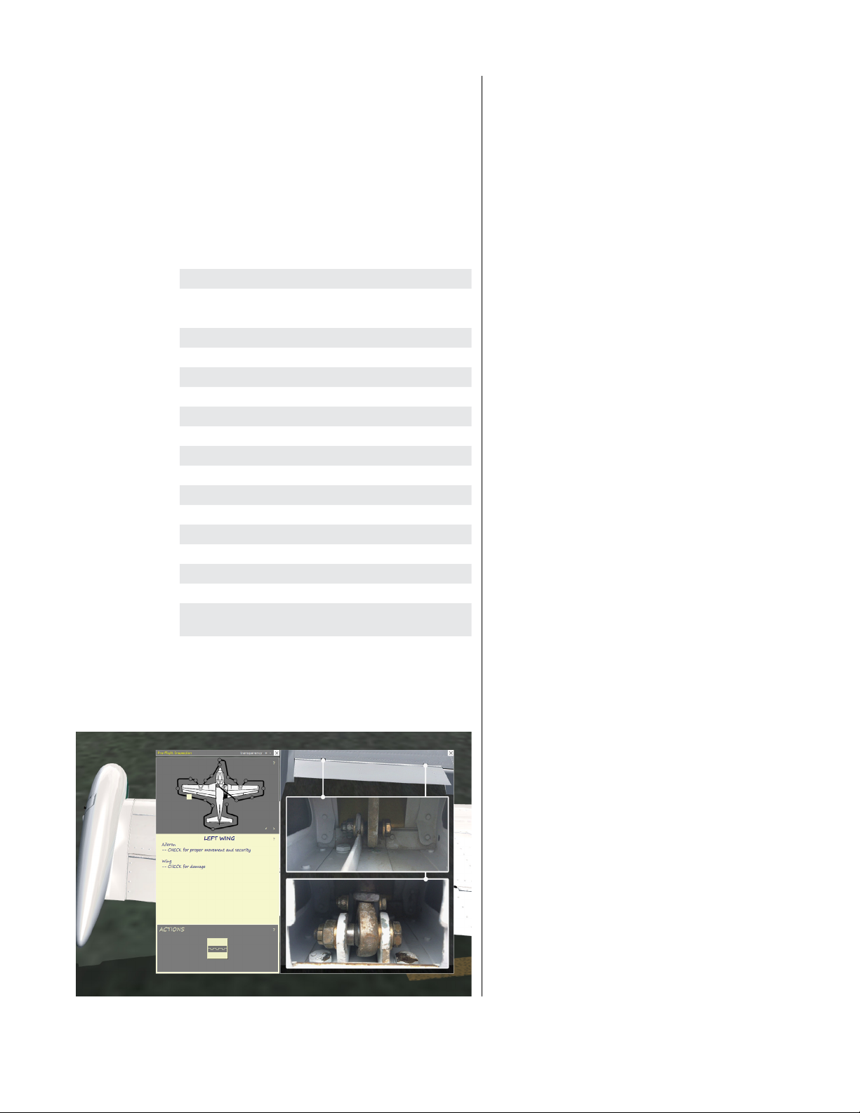
NORMAL PROCEDURES
AIRSPEEDS FOR NORMAL OPERATION
The following airspeeds are those which are significant
to the safe operation of the airplane. These figures are
for standard airplanes flown at gross weight under standard conditions at sea level.
Performance for a specific airplane may vary
from published figures depending upon the equipment installed, the condition of the engine, airplane
and equipment, atmospheric conditions and piloting
technique.
Vx Best Angle of Climb Speed 84 mph
Vy Best Rate of Climb Speed 105 mph
Vbg Best Glide Speed: Endurance 90 mph
Best Glide Speed: Range 105 mph
Vs Stall Speed, normal configuration 71 mph
Vso Stall Speed, landing configuration 64 mph
Recommended Flap Extension Speed 100 mph
Vfe Maximum Flap Extension Speed 125 mph
Vlo
Maximum Landing Gear Operation Speed
Vle Maximum Landing Gear Extended Speed 150 mph
Va Maneuvering Speed (at gross weight) 144 mph
Vno Maximum Structural Cruising Speed 180 mph
Vne Never Exceed Speed 203 mph
(with stabilator tips installed) 229 mph
Normal Climb Out 120 mph
Short Field T/O, Flaps 18°, rotate 83 mph
Final Approach, Flaps Up 95 mph
Final Landing Approach, Flaps 27° 90 mph
Maximum Demonstrated
Crosswind Velocity
125 mph
17 kts
PREFLIGHT
When the aircra is stopped with the engine o, press
SHIFT-8 to bring up the interactive preflight inspection.
STARTING
Aer completion of preflight inspection:
1. Fuel selector to the proper tank.
2. Mixture control full in, “RICH” position.
3. Carburetor heat control full in, “COLD” position.
4. Throttle open 1/4 inch.
5. Propeller control full in “INCREASE RPM” .
6. Turn master switch to “ON” position.
7. Turn the auxiliary fuel pump switch
“ON”, listen for pump to operate and
note fuel pressure indication.
8. Prime. When engine is cold (under
40° F) prime three to five strokes, if
engine is warm do not prime.
9. Check all radios for being “OFF”.
10. Check the propeller area for being “CLEAR” .
a. Engage the starter and allow the engine to
turn approximately one full revolution then
b. Turn the ignition switch to the
“Both” magneto position
c. (Limit starter operation to 30 seconds)
NOTE: If the above procedure does not start the engine reprime and repeat the process. If the engine is over-primed,
open the throttle and turn the engine over with the starter. If
the engine still fails to operate, check for malfunctioning of
ignition or fuel system.
When the engine is firing evenly, adjust the throttle
to 800 RPM. Check the oil pressure gauge for a pressure
indication. If oil pressure is not indicated within thirty
seconds, stop the engine and determine the trouble.
If the engine fails to start at the first attempt, another
attempt should be made without priming. If this fails, it
is possible that the engine is over primed. Turn the magneto switch o, open the throttle slowly, and rotate the
engine approximately ten revolutions with the starter.
Re-prime the engine with one half the amount used in
the initial attempt, turn the magneto switch to “Both”,
and repeat the starting procedure.
58
A2ASIMULATIONS
WARM-UP AND GROUND CHECK
As soon as the engine starts, the oil pressure should be
checked. If no pressure is indicated within thirty seconds, stop the engine and determine the trouble. In cold
weather it will take a few seconds longer to get an oil
pressure indication.
Warm-up the engine at 800 to 1200 RPM for not more
than two minutes in warm weather, four minutes in cold
weather. If electrical power is needed from the generator, the engine can be warmed up at 1200 RPM at which
point the generator cuts in. The magnetos should be
checked at 2000 RPM, the drop not to exceed 125 RPM
with manifold pressure of 15” MAP. The engine is warm
enough for take-o when the throttle can be opened
without the engine faltering.
:::
COMANCHE 250 MANUAL www.a2asimulations.com
FOR SIM ULATIO N USE ONLY
Page 59

Carburetor heat should be checked during the
warm-up to make sure the heat control operation is satisfactory and to clear out the carburetor if any ice has
formed. It should also be checked in flight occasionally
when outside air temperatures are between 20° F and
70° F to see if icing is occurring in the carburetor. In most
cases when an engine loses manifold pressure without
apparent cause, the use of carburetor heat will correct
the condition.
When carburetor heat is applied, cold air entering
the induction system is taken from a rear bale to an
exhaust pipe shroud, then to the carburetor; it is not
filtered. For this reason carburetor heat should not be
used on the ground in dusty conditions except momentarily during the run-up. Dust taken into the intake
system can damage the engine severely, and caution
must always be exercised during ground operation to
prevent dust from entering the engine.
The propeller control should be moved through its
normal range during the warm-up to check for proper
operation, then le in the full high RPM position. During
cold weather operation the propeller should be cycled a
minimum of three times to insure that warm engine oil
has circulated throughout the system.
During the propeller check, as during other ground
operations, care must be taken not to run-up the engine
with the propeller over loose stones, cinders or other
objects which can be picked up by the propeller, and
which frequently cause extensive damage to the propeller blades .
TAKE-OFF
Just before take-o the following items should be
checked:
1. Controls free
2. Flaps set
3. Tab set
4. Propeller set
5. Mixture rich
6. Carburetor heat off
7. Fuel on proper tank
8. Electric fuel pump on
9. Engine gauges normal
10. Door latched
11. Safety belts fastened
In a smooth, steady motion of the throttle apply full
power allowing the aircra to accelerate in the three
point attitude until the control surfaces become eective. Then apply slight back pressure on the control
column to li the nose wheel. Under normal take-o
conditions the Comanche will leave the ground at
about 65 M. P.H. Trying to pull the aircra o before
the proper speed is obtained will only prolong the
take-o run. Aer the take-o has proceeded to the
point at which a landing could no longer be made with
the wheels down in the event of power failure, the gear
should be retracted. As soon as the gear is up and sufficient altitude has been gained, reduce power to climb
setting.
www.a2asimulations.com COMANCHE 250 MANUAL
FOR SIM ULATIO N USE ONLY
:::
A2ASIMULATIONS
59
Page 60
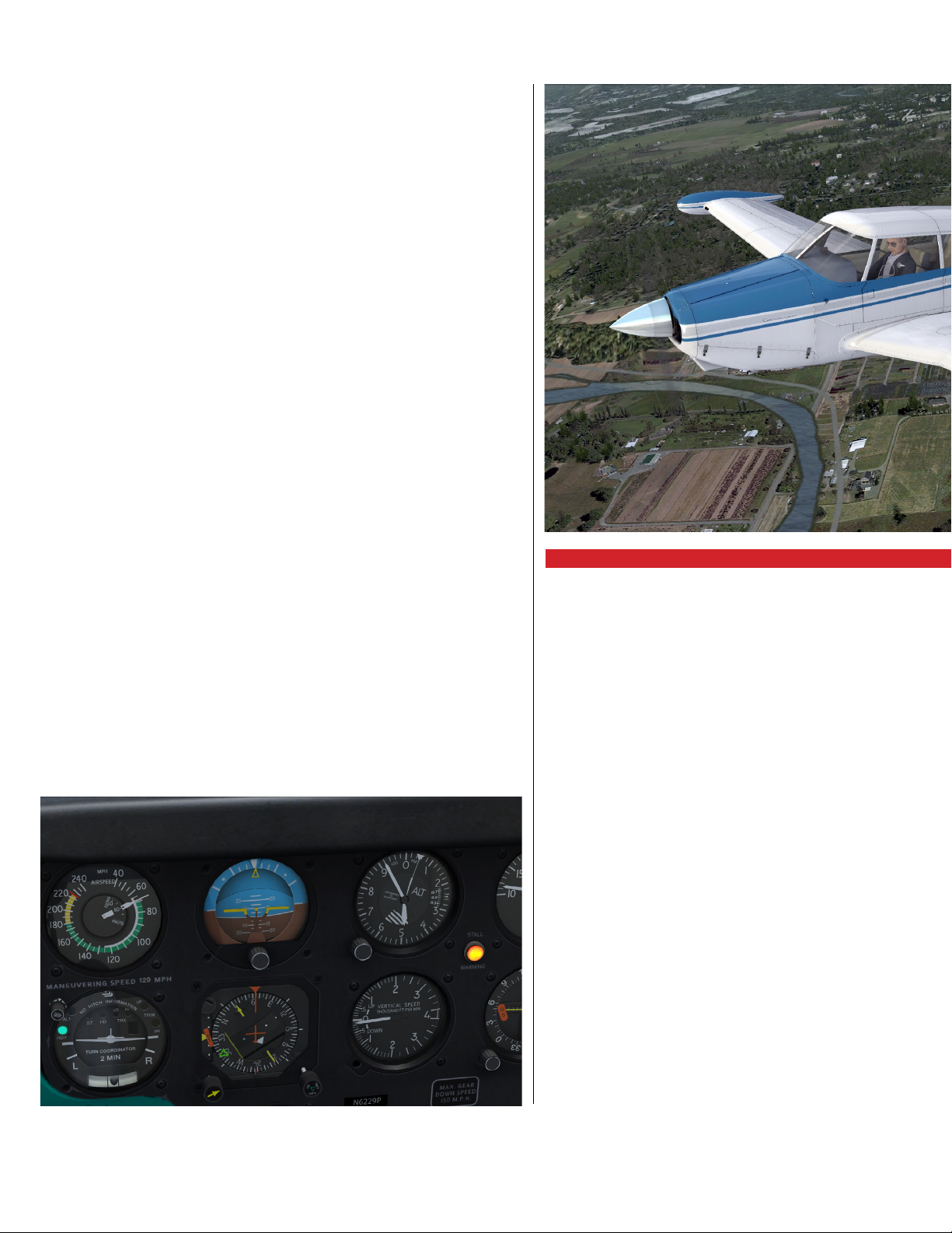
NORMAL PROCEDURES
For a minimum take-o run in the Comanche 250,
the flaps should be lowered to the recommended 18°
() position. With the flaps in this position the take-o
run will be reduced approximately 20 per cent.
Normally flaps are not used during crosswind takeos. It is desirable to hold the nose wheel on the runway
until a higher than normal take-o speed is obtained,
then apply a definite but not abrupt back pressure to
the control column to li the aircra from the runway.
Once airborne, set up the required crab angle, retract
the gear,and continue the climbout.
During cold weather operation, when taking o from
slush or water covered runways, allow the gear to remain
down longer than usual so that any slush remaining on
the gears will freeze and will be broken away when the
wheels are retracted.
CLIMB
Max recommended climb power is 2,400 RPM at 24”
manifold pressure. The best rate of climb is obtained
at 105 MPH This speed should be decreased about 1
MPH. per thousand feet of altitude so that at 10,000
feet the best airspeed for maximum rate of climb is 95
MPH A good rate of climb is obtained at lower altitudes
is 110 to 120 MPH, while forward speed is increased.
Reducing the climbing airspeed below 95 MPH at low
altitudes has the added disadvantage of cutting down
forward visibility and reducing airflow for engine cooling. Extended climbs at speeds below that figure are not
recommended.
STALLS
The gross weight stalling speed with flaps and gear
down is 61 MPH The stall speed will increase about
7 MPH in the clean configuration. All controls are eective at speeds down to the stalling speed. Stalls are
gentle and the airplane is easily controlled if back pressure is released from the yoke.
CRUISING
The cruising speed of the Comanche models is determined by many factors including power setting, altitude, temperature, load and equipment installed on the
airplane. The 250 Comanche has a maximum recommended cruising speed of 182 MPH. At 75% power at
7000 feet, 2400 RPM and 22.6” MAP Fuel consumption at
this speed approximates 14 gallons per hour when leaning to Best Economy Cruise (Peak EGT). To keep engine
wear, fuel consumption, and noise at reasonable levels,
cruising RPM’s from 2000 to 2400 are recommended
with appropriate Manifold Pressures to obtain power
settings of 65% to 75% power at low and intermediate
altitudes.
For maximum eiciency (highest cruising range),
the best power settings during cruising flight are with
minimum RPM and the necessary Manifold Pressures
to obtain a given percent of power, consistent with
the recommended limitations. Engine smoothness
and noise level should be major factors in determining the best RPM. Use of the mixture control in cruising
flight reduces fuel consumption significantly, especially at higher altitudes. The mixture should always
be leaned during cruising operation over 5000 feet altitude, and normally also at lower altitudes at the pilot’s
discretion.
The continuous use of carburetor heat during cruising flight reduces power and performance. Unless icing
60
A2ASIMULATIONS
:::
COMANCHE 250 MANUAL www.a2asimulations.com
FOR SIM ULATIO N USE ONLY
Page 61

conditions in the carburetor are severe, do not cruise
with the heat on. Apply heat slowly and only for a few
seconds at intervals determined by icing severity.
In order to keep the airplane in best lateral trim
during cruising, the fuel should be used alternately from
each tank. If tip tanks are installed, it is suggested to use
the fuel in the tip tanks first.
CAUTION: In keeping with general practice for all aircra, it is recommended that when flying in turbulent
air or active weather such as storm conditions, that the
aircra not exceed it’s turbulent air penetration speed,
also known as maneuvering speed which is 129 mph.
APPROACH AND LANDING
Before Landing Check List:
1. Mixture “RICH”.
2. Propeller set.
3. Carburetor heat “OFF” (unless
icing conditions exist).
4. Electric fuel pump “ON” .
5. Fuel selector on proper tank.
6. Landing gear “DOWN”, under 150 MPH (Check
green light “ON”, warning horn “OFF’’, gear
emergency handle in “FORWARD” position.)
7. Flaps as desired (under 125 MPH)
8. Safety belts fastened
During the approach, the landing gear can be lowered at 150 MPH or lower, preferably on the downwind
leg. The flaps can be lowered at 125 MPH or below, if
desired. For final approach, trim the aircra to approximately 90 MPH with full flaps, or approximately 95 MPH
with no flaps. The propeller should be set for high RPM
to facilitate a go-around if required. Carburetor heat
generally is not applied during landing unless icing conditions are suspected. If a landing is aborted move the
carburetor heat to the o position immediately if full
power is desired .
The amount of flap used during landings and the
speed of the aircra at contact should be varied according to the wind, the landing surface, and other factors.
It is always best to contact the ground at the minimum
practicable speed consistent with landing conditions.
Normally, the best technique for short and slow
landings is to use full flap and a small amount of power,
holding the nose up as long as possible before and aer
ground contact. In high wind conditions, particularly in
strong crosswinds, it may be desirable to approach the
ground at higher than normal speeds with partial or
no flap.
Maximum braking eect during short field landings
can be obtained by holding full back on the control
wheel with flaps up while applying brakes. This forces
the tail down and puts more load on the main wheels,
resulting in better traction.
A handy way to remember critical landing in a high
performance retractable plane is to say: “GUMPS”
GAS — Fuel selectors on desired tank
with fuel pump ON
UNDERCARRIAGE — Down and locked
MIXTURE — RICH (In)
PROP — HIGH (In)
SEATBELTS — ON
WEIGHT AND BALANCE -
It is the responsibility of the owner and pilot to determine that the airplane remains within the allowable
weight vs center of gravity envelope while in flight.
For weight and balance data see the latest Weight and
Balance Form supplied with each airplane.
www.a2asimulations.com COMANCHE 250 MANUAL
FOR SIM ULATIO N USE ONLY
:::
A2ASIMULATIONS
61
Page 62

PERFORMANCE
HE PERFORMANCE INFORMATION PRESENTED
in this section is based on measured Flight Test
T
and analytically expanded for the various parameters of
weights, altitude, temperature, etc. The performance
charts are unfactored and do not make any allowance
for varying degree of pilot proficiency or mechanical
deterioration of the aircra. The performance however
can be duplicated by following the stated procedures in
a properly maintained airplane.
such as the eect of so or grass runway surface on takeo and landing performance,
or the eect of winds alo on cruise and range performance. Endurance can be greatly
aected by improper leaning procedures, and in-flight fuel flow and quantity checks are
recommended.
Data corrected to ICAO standard day conditions
Eects of conditions not considered on the charts must be evaluated by the pilot,
62
A2ASIMULATIONS
:::
COMANCHE 250 MANUAL www.a2asimulations.comFOR SIM ULATIO N USE ONLY
Page 63

www.a2asimulations.com COMANCHE 250 MANUAL
FOR SIM ULATIO N USE ONLY
:::
A2ASIMULATIONS
63
Page 64

PERFORMANCE
64
A2ASIMULATIONS
:::
COMANCHE 250 MANUAL www.a2asimulations.com
FOR SIM ULATIO N USE ONLY
Page 65

www.a2asimulations.com COMANCHE 250 MANUAL
FOR SIM ULATIO N USE ONLY
:::
A2ASIMULATIONS
65
Page 66

PERFORMANCE
66
A2ASIMULATIONS
:::
COMANCHE 250 MANUAL www.a2asimulations.com
FOR SIM ULATIO N USE ONLY
Page 67

www.a2asimulations.com COMANCHE 250 MANUAL
FOR SIM ULATIO N USE ONLY
:::
A2ASIMULATIONS
67
Page 68

PERFORMANCE
68
A2ASIMULATIONS
:::
COMANCHE 250 MANUAL www.a2asimulations.com
FOR SIM ULATIO N USE ONLY
Page 69

www.a2asimulations.com COMANCHE 250 MANUAL
FOR SIM ULATIO N USE ONLY
:::
A2ASIMULATIONS
69
Page 70

WEIGHT AND BALANCE
70
A2ASIMULATIONS
:::
COMANCHE 250 MANUAL www.a2asimulations.comFOR SIM ULATIO N USE ONLY
Page 71

N ORDER TO ACHIEVE THE PERFORMANCE AND FLYING
characteristics which are designed into the airplane, it must
I
be flown with the weight and center of gravity (C.G.) posi
tioned within the approved operating range (envelope). Although
the airplane oers flexibility of loading, it cannot be flown with the
maximum number of adult passengers, full fuel tanks, and maxi
mum baggage. With the flexibility comes responsibility. The pilot
must ensure that the airplane is loaded within the loading enve
lope before he makes a takeo.
Misloading carries consequences for any aircra. An
overloaded airplane will not take o, climb, or cruise as
well as a properly loaded one. The heavier the airplane
is loaded, the less climb performance it will have.
Center of gravity is a determining factor in flight characteristics. If the C.G. is too far forward in any airplane,
it may be diicult to rotate for takeo or landing. If the
C.G. is too far a, the airplane may rotate prematurely
on takeo or tend to pitch up during climb. Longitudinal stability will be reduced. This can lead to inadvertent stalls and even spins, and spin recovery becomes
more diicult as the center of gravity moves a of the
approved limit.
WEIGHT AND BALANCE LOADING FORM
For use with Tip Tanks and MT propeller.
(example using two 170 lbs passengers, full fuel, and 50lbs of baggage)
Weight
(lbs.) Arm A
Basic Empty
Weight
Front Seats 340 84.8 28,832
Rear Seats* 0 118.5 0
Main Fuel
(max 60gal)
Tip Tanks
(max 30gal)
Baggage* 50 142 7,100
Tot al 2,639 222,187
NOTE: Typically, empty weight includes unusable fuel, but
in A2A’s “29p” pilot’s operating manual, it does not.
1709 83.9 143,385
360 90.0 32,400
180 91.5 16,470
Datum
(in.)
Moment
(in-lbs.)
-
-
-
How to calculate the center of gravity:
Total Moment ÷ Total Weight = C.G. (center of gravity)
222,187 ÷ 2,639 = 84.19
C.G. = 84.19
www.a2asimulations.com COMANCHE 250 MANUAL
FOR SIM ULATIO N USE ONLY
:::
A2ASIMULATIONS
71
Page 72
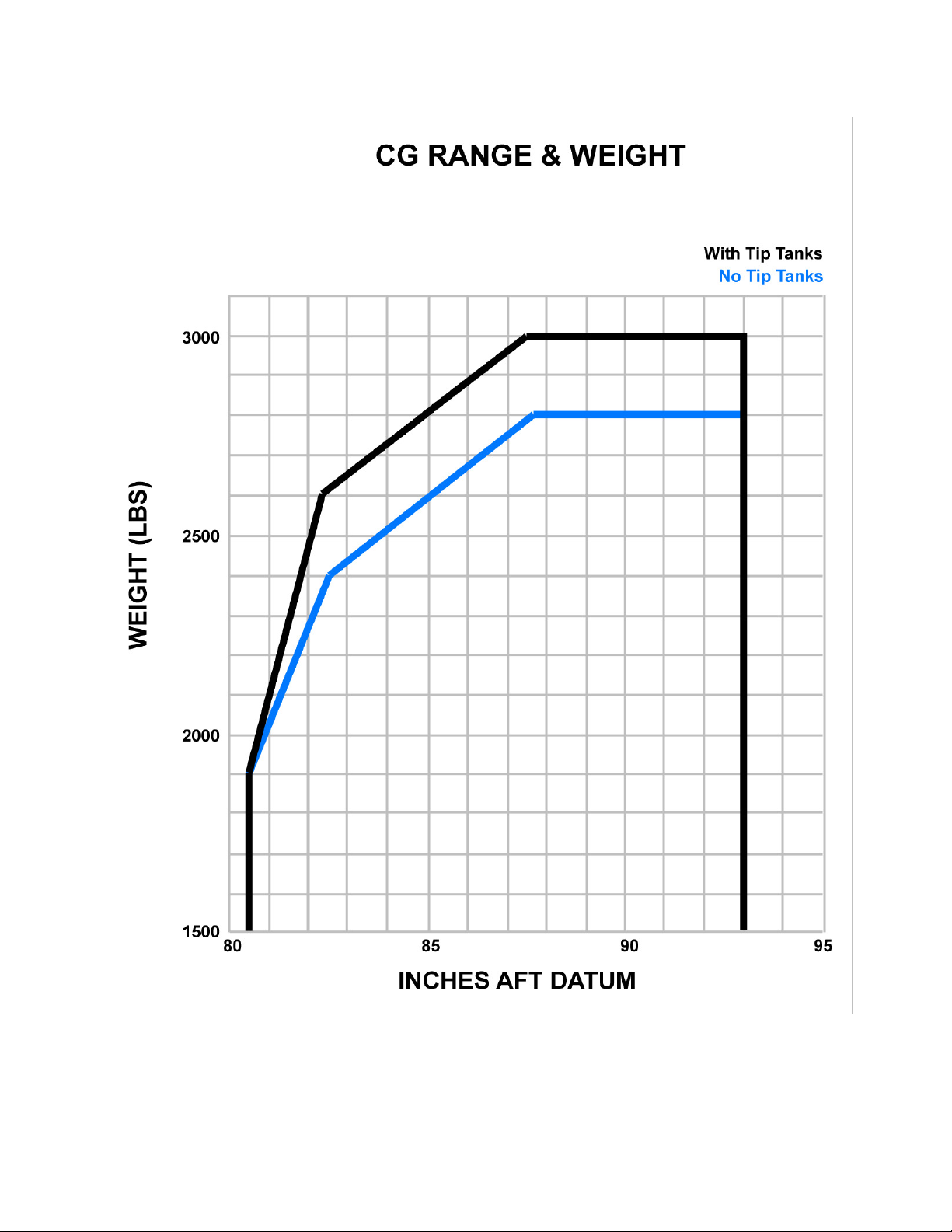
WEIGHT AND BALANCE
72
A2ASIMULATIONS
:::
COMANCHE 250 MANUAL www.a2asimulations.com
FOR SIM ULATIO N USE ONLY
Page 73

www.a2asimulations.com COMANCHE 250 MANUAL
FOR SIM ULATIO N USE ONLY
:::
A2ASIMULATIONS
73
Page 74

AIRPLANE & SYSTEM DESCRIPTIONS
74
A2ASIMULATIONS
:::
COMANCHE 250 MANUAL www.a2asimulations.comFOR SIM ULATIO N USE ONLY
Page 75
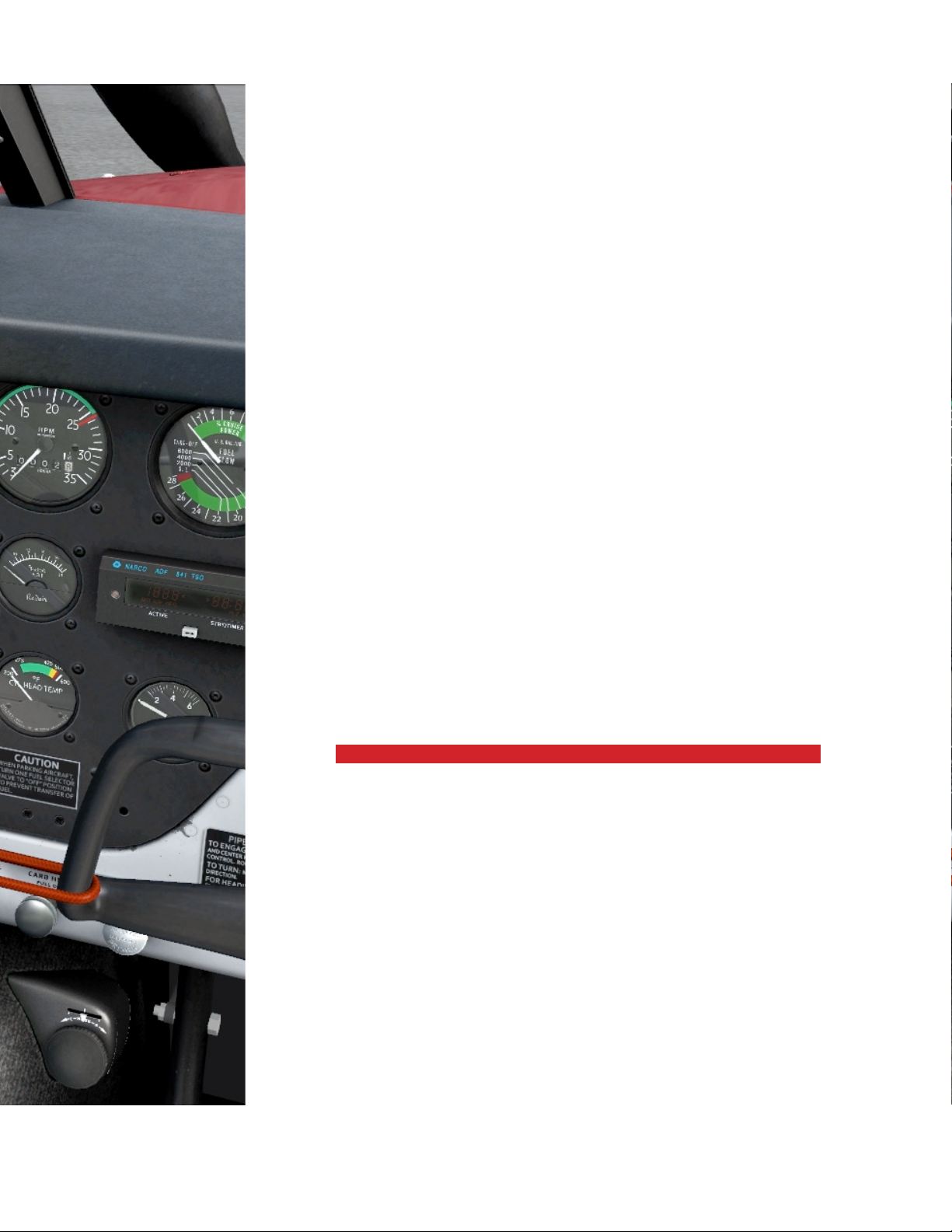
HE PA-24-250 COMANCHE
is a single-engine, low-wing,
T
retractable landing gear
monoplane of all metal construc
tion. It has four place seating, two
hundred pound baggage capacity,
and a 250 horsepower engine.
ENGINE AND PROPELLER
The Comanche PA-24-250 is powered by a Lycoming O-540-A engine (direct drive,
wet sump, horizontally opposed), developing 250 HP at 2575 RPM. The compression
ratio of 8.5 to 1 and the minimum required use of 91/96 Aviation fuel.
The engine is furnished with a geared starter, alternator, vacuum pump drive, and
carburetor air box and filter.
Exhaust gases from the engine are carried overboard through an exhaust manifold. The manifold incorporates a stainless steel muler fitted with a heater shroud
which provides heat for both the cabin interior and the carburetor heat system.
Engine cooling is accomplished without the usual cowl flaps, exhaust augmenters, or drag producing fixed cowl flanges.
There are two dierent models of propellers used for the A2A Accu-Sim simulator:
1. McCauley constant speed 77” diameter 3-blade
2. MT Propeller constant speed 74” diameter 3-blade
Both propellers are controlled by a governor mounted on the engine which supplies oil to the propeller through the engine sha. The governor in turn is controlled
by the propeller control in the cockpit.
-
www.a2asimulations.com COMANCHE 250 MANUAL
FOR SIM ULATIO N USE ONLY
:::
A2ASIMULATIONS
75
Page 76

AIRPLANE & SYSTEM DESCRIPTIONS
STRUCTURES
Structures are of sheet aluminum construction, and
are designed to ultimate load factors well in excess of
normal requirements. All components are completely
zinc chromate primed, exterior surfaces are coated with
acrylic lacquer.
The main spars of the wings are jointed with high
strength butt fittings in the center of the fuselage, making in eect a continuous main spar. The spars are attached to the fuselage at the side of the fuselage and in
the center of the structure; wings are also attached at
the rear spar and at an auxiliary front spar.
The wing airfoil section is a laminar flow type, NACA642A215, with maximum thickness about 40% a of the
landing edge. This permits the main spar, located at the
point of maximum thickness, to pass through the cabin
under the rear seat, providing unobstructed cabin floor
space ahead of the rear seat.
LANDING GEAR
The nose gear is steerable with the rudder pedals
through a 40 degree arc. During retraction of the gear
the steering mechanism is disconnected automatically
to reduce rudder pedal loads in flight. The nose gear is
equipped with a hydraulic shimmy dampener.
Retraction of the landing gear is accomplished
through the use of an electric motor and gear train located under the floorboards, actuating push- pull cables
to each of the gears. The landing gear motor is activated
by a selector switch located on the instrument panel.
As an added safety feature, the warning horn is connected to the gear selector switch. The horn will then
operate if the selector is moved to the “UP” position
with the master switch on and the weight of the airplane
is on the landing gear. As a final safety factor to prevent
gear retraction on the ground, an anti-retraction switch
is installed on the le main gear. This prevents the electric circuit to the landing gear motor from being completed until the gear strut is fully extended. A green light
on the instrument panel below the landing gear switch
is the indication that all gears are down and locked. The
warning horn will also sound if the power is reduced
below approximately 12” of manifold pressure and the
gear has not been lowered.
The telescoping emergency gear handle should not
be used as the primary indication that the gear is down
and locked. An amber light above the switch indicates
gears up. THE INDICATION LIGHTS ARE AUTOMATI-
CALLY DIMMED WHEN THE NAVIGATION LIGHTS ARE
TURNED ON.
The brakes on the Comanche are actuated by toe
brake pedals mounted on the le set of rudder pedals
or by a hand lever protruding from under the instrument
panel. Hydraulic brake cylinders are located above the
le rudder pedals and are accessible in the cockpit for
servicing. Parking brake valves are incorporated in each
76
A2ASIMULATIONS
:::
COMANCHE 250 MANUAL www.a2asimulations.com
FOR SIM ULATIO N USE ONLY
Page 77

cylinder. Two cables extending from the parking brake
“T” handle are attached to the parking brake valves. To
prevent inadvertent application of the parking brake
in flight, a safety lock is incorporated in the valves thus
eliminating the possibility of pulling out the “T” handle
until pressure is applied by use of the toe brakes or the
hand lever.
CONTROL SYSTEMS
The flight controls on the Comanches are the conventional three control type operated by a control column
and rudder pedals. The movable stabilator, with an
anti-servo tab which also acts as a longitudinal trim tab
provides extra stability and controllability with less size
drag and weight.
Provision for directional and longitudinal trim is provided by an adjustable trim mechanism for the rudder
and stabilator. Dual flight controls are installed in the
Comanche as standard equipment.
A hand brake is provided to operate the brakes while
occupying the right seat.
The flaps on the Comanche are mechanically operated and can be positioned in the three locations of
9°, 18° , and 27°. Locks on the inboard ends of the flaps
hold them in the “UP” position so the right flap can be
stepped on for entry or exit. A second lock is incorporated to prevent the flap from going full down in case
a step load is applied and the full up lock was not fully
engaged.
COMANCHE OWNER’S NOTE: Even though technically the
flaps can hold the weight of a person, most if not all Coman
che owners we know don’t let people use the flaps as a step.
FUEL SYSTEM
The fuel for the Comanche is carried in two rubber-like
fuel cells located in the inboard leading edge sections of
the wings. Capacity of these cells, which are classified as
the main fuel cells, are 30 gallons each.
60 gallons is the standard fuel capacity of which 56
gallons is usable; however, if tip tanks are installed the
fuel capacity is increased to 90 gallons of which a total
of 84 gallons is usable.
During normal operation the fuel is drawn to the engine from the cell by a mechanically operated fuel pump
located on the engine accessory section. In the event
the engine driven fuel pump fails, two electric auxiliary
fuel pump are provided. The pumps are operated (via
a single switch) during starting, take-os, and landings.
The fuel strainer, equipped with a quick drain, is
mounted under the right forward section of the fuselage. The strainer should be drained regularly to check
for water or dirt accumulations.
The procedure for draining the right and le tanks
and lines is to open the gasculator quick drain for a few
seconds with the fuel tank selector on one tank. Then
change the fuel selector to the opposite tank and repeat
the process, allowing enough fuel to flow out to clear
the line as well as the gasculator.
ELECTRICAL SYSTEM
Electrical power for the Comanche is supplied by a 12
volt, direct current system. Incorporated in the current
system is a alternator, which furnishes electrical power
during all normal operation. A 12 volt 33 ampere hour
battery is used in the system to provide power for starting and as a reserve power source in case of alternator
failure. The battery is located behind the baggage compartment bulkhead in a sealed stainless steel battery
box. Refer to the Maintenance Section for servicing of
-
the battery.
Electrical switches and circuit breakers for the different systems are located on the lower le instrument
panel. The circuit breakers automatically break the
electrical circuit if an overload is applied to the system,
thereby preventing damage to the component and wiring.
To reset the circuit breakers simply push in the reset
button. Allow approximately two minutes for breakers
to cool prior to resetting. Continual popping out of a
circuit breaker indicates trouble in that circuit and must
be checked prior to operation. It is possible to manually
trip the breaker by pulling out on the reset button.
HEATING AND VENTILATING SYSTEM
There are four individual controls provided for regulating the heating, defrosting, and forward fresh ventilating air. The controls are located on the lower right side
of the instrument panel in the console panel.
Heated air for the cabin is provided by a heater
shroud attached by the exhaust muler. Fresh air is
picked up at the rear engine bale and passed through
the heater shroud into a control valve for distribution to
the cabin.
Warm air for the defroster system is obtained directly
from the heater shroud. The amount of air applied to the
www.a2asimulations.com COMANCHE 250 MANUAL
FOR SIM ULATIO N USE ONLY
:::
A2ASIMULATIONS
77
Page 78

AIRPLANE & SYSTEM DESCRIPTIONS
windshield is regulated with the control in the console.
Caution should be used if it is necessary to operate the
defroster on the ground as prolonged application of
heat to the windshield may cause distortion.
Fresh air for the cabin interior is picked up from two
air scoops attached to the lower engine cowling. The
air passes through flexible hoses to control valves on
the firewall where the flow is regulated to the cabin. Located at each seat are two smaller air vents that may be
regulated by the individual.
Located in the a section of the cabin is an exhaust
vent to improve the circulation of air in the cabin interior.
INSTRUMENT PANEL
The instrument panel in the Comanche is designed to
accommodate the customary advanced flight instruments on the le side in front of the pilot and the engine
instruments on the right side. Provisions for extra instruments are made in both sections. Instruments are shock
mounted and accessible for maintenance by removing a
portion of the fuselage cowl over the instruments.
The artificial horizon and the directional gyro in the
flight group are vacuum operated through the use of a
vacuum pump installed on the engine. The turn coordinator is an electrically operated instrument and serves as
a standby for the other gyros in case of vacuum system
failure (partial panel).
Radios are installed in the le of the panel. Radio
power supplies are mounted a of the baggage compartment.
SEATS
Front seats are adjustable so as to provide comfort and
facilitate ease of entry and exit from the aircra for pilot and passengers. They are easily removed by taking
out the stops at the end of the mounting tracks and sliding the seats o their tracks. The back of the rear seat is
adjusted to various fore and a positions by use of the
latches at the outboard upper corners. The entire rear
seat is removed quickly by disengaging the a seat bottom tube from its attachment clamps, detaching the
latches behind the top of the seat back, removing the
center safety belt bolt, then liing both the seat and the
back as one unit from the cockpit.
CENTER STACK AVIONICS SUITE
We have spent much time developing extra modes and
functions that you won’t find in any Prepar3D airplane,
like independent DME receiver, pilot- programmable
COMM channels and NAV OBS mode. For example, you
should pay attention to the autopilot. Even though it
may look familiar, you need to learn how to operate it
properly or you may find you plane going in completely
wrong direction.
The avionics suite in your Accu-Sim Piper Comanche
250 is so complete, the best source for your information
is straight from the manufacturer. Below are links to the
latest manuals online:
http://.a2asimulations.com/downloads/manuals/
STEC%2020-30-30alt.pdf
BAGGAGE COMPARTMENT
Maximum placarded weight of the baggage area is 200
pounds with 20 cubic feet of area available, accessible
through a 20 x 20 inch door. Provision for securing cargo
is provided by tie-down belts installed in the compartment. Attached to the top of the baggage compartment
are provisions for stowing the tow bar. The key used in
the ignition operates the lock on the baggage compartment door.
http://a2asimulations.com/downloads/manuals/
ADF841.pdf
http://a2asimulations.com/downloads/manuals/
MK12E-NCS812-Manual.pdf
78
A2ASIMULATIONS
:::
COMANCHE 250 MANUAL www.a2asimulations.com
FOR SIM ULATIO N USE ONLY
Page 79

www.a2asimulations.com COMANCHE 250 MANUAL
FOR SIM ULATIO N USE ONLY
:::
A2ASIMULATIONS
79
Page 80

AIRPLANE & SYSTEM DESCRIPTIONS
80
A2ASIMULATIONS
:::
COMANCHE 250 MANUAL www.a2asimulations.com
FOR SIM ULATIO N USE ONLY
Page 81
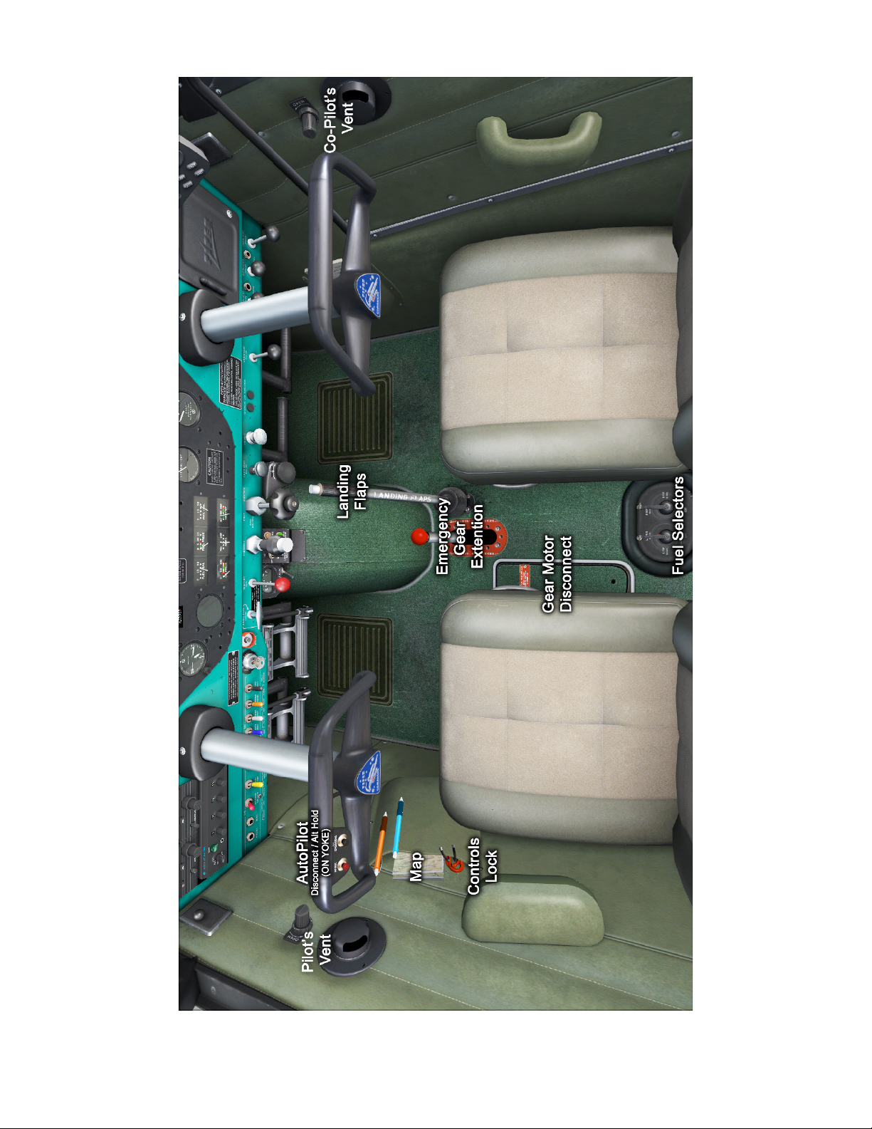
www.a2asimulations.com COMANCHE 250 MANUAL
FOR SIM ULATIO N USE ONLY
:::
A2ASIMULATIONS
81
Page 82

AIRPLANE & SYSTEM DESCRIPTIONS
82
A2ASIMULATIONS
:::
COMANCHE 250 MANUAL www.a2asimulations.com
FOR SIM ULATIO N USE ONLY
Page 83

www.a2asimulations.com COMANCHE 250 MANUAL
FOR SIM ULATIO N USE ONLY
:::
A2ASIMULATIONS
83
Page 84

EMERGENCY PROCEDURES
HIS SECTION CONTAINS PROCEDURES THAT ARE RECOMMENDED
if an emergency condition should occur during ground operation, take
T
action for coping with the particular condition described, but are not a sub
stitute for sound judgment and common sense. Since emergencies rarely
happen in modern aircra, their occurrence is usually unexpected, and the
best corrective action may not always be obvious. Pilots should familiar
ize themselves with the procedures given in this section and be prepared to
take appropriate action should an emergency arise.
Most basic emergency procedures, such as power o landings, are a normal part of pilot training. Although these emergencies are discussed here, this information is not intended to
replace such training, but only to provide a source of reference
84
o, or in flight. These procedures are suggested as the best course of
and review, and to provide information on procedures that are
not the same for all aircra. It is suggested that the pilot review
standard emergency procedures periodically to remain proficient in them.
A2ASIMULATIONS
:::
COMANCHE 250 MANUAL www.a2asimulations.comFOR SIM ULATIO N USE ONLY
-
-
-
Page 85

ENGINE POWER LOSS
POWER OFF LANDING
DURING TAKEOFF
1. If suicient runway remains for a
normal landing, leave gear down
and land straight ahead.
2. 2. If insuicient runway remains:
a. Airspeed — Maintain Safe Airspeed
b. Landing Gear — As Situation Requires
c. Flaps — As Situation Requires
3. If suicient altitude has been
gained to attempt a restart:
a. Maintain safe airspeed.
b. Fuel selector — Switch to
tank containing fuel
c. Electric fuel pump — ON
d. Mixture — Check RICH
e. Alternate air — OPEN
4. If power is not regained, proceed
with power o landing.
ENGINE POWER
LOSS IN FLIGHT
1. Airspeed — Establish Best Glide Speed
(100 mph @ Full Gross Weight)
2. Fuel selector — switch to tank containing fuel
3. Electric fuel pump — ON
4. Mixture — RICH
5. Carburetor Heat — ON
6. Primer — Check In and Locked
7. Magnetos — le/right/both if no change
8. Engine gauges — check for indication
of cause of power loss
9. If no fuel pressure is indicated, check
tank selector position to be sure it
is on a tank containing fuel.
a. When power is restored:
Carburetor Heat — OFF
b. Electric fuel pump — OFF
10. If power is not restored, prepare
for power o landing
a. Trim for 97 MPH.
1. Trim for 97 MPH.
2. Locate suitable field.
3. Establish a spiral pattern.
4. Transponder to 7700. Radio to
121.5 and broadcast Mayday.
5. 1000 . above field at downwind position
for normal landing approach. When field
can be easily reached, extend gear, flaps
and slow to 87 MPH for shortest landing.
GEAR DOWN EMERGENCY
LANDING
1. Touchdowns should normally be made at
lowest possible airspeed with full flaps.
2. When committed to landing:
3. Landing gear selector — DOWN
4. Throttle — CLOSE
5. Mixture — IDLE CUT-OFF
6. Ignition — OFF
7. Master switch — OFF
8. Fuel selector — OFF
9. Seat belt and harness — Tight
10. Door — Unlatch
GEAR UP EMERGENCY
LANDING
1. In the event a gear up landing is
required, proceed as follows:
2. Flaps — As desired
3. Throttle — Close
4. Mixture — Idle cut-o
5. Ignition switch — OFF
6. Master switch — OFF
7. Fuel selector — OFF
8. Seat belt and harness — Tight
9. Contact surface at minimum
possible airspeed.
10. Door — Unlatch
www.a2asimulations.com COMANCHE 250 MANUAL
FOR SIM ULATIO N USE ONLY
:::
A2ASIMULATIONS
85
Page 86

EMERGENCY PROCEDURES
FIRE IN FLIGHT
1. Source of fire — Check
2. 2. Electrical fire (smoke in cabin):
a. Master switch — OFF
b. Generator Circuit Breaker — Pull
c. Vents — OPEN
d. Door (As Required) — OPEN as an Exhaust
e. Cabin heat — OFF
f. Land as soon as practicable..
3. Engine fire:
a. Fuel selector — OFF
b. Throttle — CLOSED
c. Mixture — Idle cut-o
d. Electric fuel pump — Check OFF
e. Heater and defroster — OFF
f. Proceed with power o landing procedure.
HIGH OIL TEMPERATURE
1. Power — Reduce
2. Mixture — Enrich
3. Airspeed — Maintain above 120 mph
4. Land at nearest airport and
investigate the problem.
5. Prepare for a power o landing.
LOSS OF OIL PRESSURE
1. Land as soon as possible and investigate cause.
2. Prepare for power o landing.
LOSS OF FUEL PRESSURE
1. Electric fuel pump — ON
2. Fuel selector — Check on full tank
3. If the fuel pressure does not come back in a
few seconds, change to another tank with fuel.
4. Land as soon as possible. Low fuel
pressure may indicate a fuel leak.
CAUTION: If normal engine operation and fuel
flow is not immediately re-established, the electric fuel pump should be turned o. The lack of
a fuel flow indication while in the ON position
could indicate a leak in the fuel system, or fuel
exhaustion
HIGH CYLINDER HEAD
TEMPERATURE
Excessive cylinder head temperature
may parallel high oil temperature. The
procedure for handling it is the same. Refer
to High Oil Temperature procedure.
ALTERNATOR FAILURE
1. Verify failure
2. Reduce electrical load as much as possible.
3. Alternator circuit breakers — check
4. Alt switch — OFF 1 second then on
5. If no output:
a. Alt switch — OFF
b. Reduce electrical load and
land as practical.
86
A2ASIMULATIONS
:::
COMANCHE 250 MANUAL www.a2asimulations.com
FOR SIM ULATIO N USE ONLY
Page 87

SPIN RECOVERY
PROPELLER OVERSPEED
1. Throttle — IDLE
2. Ailerons — NEUTRAL
3. Rudder — Full opposite to direction of rotation
4. Control wheel — Full forward
5. Rudder — Neutral when rotation stops
6. Control wheel — Smoothly
regain level flight altitude
CARBURETOR ICING
1. Carburetor Heat — ON
2. Mixture — Max smoothness
ENGINE ROUGHNESS
1. Carburetor heat — ON
2. If roughness continues aer one min:
a. Carburetor heat — OFF
b. Mixture — Max smoothness
c. Electric fuel pump — ON
d. Fuel selector — Switch tanks
e. Engine gauges — Check
f. Magneto switch — “L” & “R” then BOTH
If operation is satisfactory on either one,
continue on that magneto at reduced
power and full “RICH” mixture to first
airport. Prepare for power o landing
OPEN DOOR
If the latch opens, the door will trail slightly
open and airspeeds will be reduced slightly.
Fly the airplane and return to land.
1. Throttle — Retard
2. Oil pressure — Check
3. Prop control — Full DECREASE rpm,
then set if any control available
4. Airspeed — Reduce
5. Throttle — As required to remain below red line
EMERGENCY LANDING
GEAR EXTENSION
(DISCUSSION ONLY)
Prior to emergency extension procedure:
1. Master switch — Check ON
2. Circuit breakers — Check
3. Instrument lights — OFF (in daytime)
4. Gear indicator bulbs — Check
5. To extend the gear, remove the plate
covering the emergency disengage control
and proceed in these steps as listed:
a. Reduce power - Airspeed
100 MPH or below.
b. Gear selector “down locked” position
c. Disengage motor - raise motor release
arm and push forward through full travel.
d. Rotate gear extension handle FULL
FORWARD to extend landing gear
and engage emergency safety lock.
Pull a on the handle to check
that the safety lock is engaged.
e. HANDLE LOCKED in full forward position
indicates landing gear is down and
emergency safety lock engaged. Gear
“down locked” indicator light should
be ON. Proceed to land normally.
NOTE: In the simulator, the above
emergency landing gear extension is
accomplished by clicking on the red
knob on the emergency landing gear
extension handle.
www.a2asimulations.com COMANCHE 250 MANUAL
FOR SIM ULATIO N USE ONLY
:::
A2ASIMULATIONS
87
Page 88

EMERGENCY PROCEDURES EXPLAINED
88
A2ASIMULATIONS
:::
COMANCHE 250 MANUAL www.a2asimulations.comFOR SIM ULATIO N USE ONLY
Page 89

HE FOLLOWING PARAGRAPHS ARE PRESENTED TO SUPPLY
additional information for the purpose of providing the pilot
T
with a more complete understanding of the recommended
course of action and probable cause of an emergency situation.
ENGINE POWER LOSS DURING TAKEOFF
The proper action to be taken if loss of power occurs
during takeo will depend on the circumstances of the
particular situation.
If suicient runway remains to complete a normal
landing, keep the landing gear down and locked, and
land straight ahead.
If insuicient runway remains, maintain a safe airspeed and make only a shallow turn if necessary to
avoid obstructions. Use of flaps depends on the circumstances. Normally, flaps should be fully extended for
touchdown.
If suicient altitude has been gained to attempt a
restart, maintain a safe airspeed and switch the fuel
selector to another tank containing fuel. Check the electric fuel pump to ensure that it is “ON” and that the mixture is “RICH.” The carburetor heat should be “ON” and
the primer checked to ensure that it is locked.
If engine failure was caused by fuel exhaustion,
power will not be regained aer switching fuel tanks
until the empty fuel lines are filled. This may require up
to ten seconds.
If power is not regained, proceed with the Power O
Landing procedure.
ENGINE POWER LOSS IN FLIGHT
Complete engine power loss is usually caused by fuel
flow interruption and power will be restored shortly
aer fuel flow is restored. If power loss occurs at a low
altitude, the first step is to prepare for an emergency
landing. An airspeed of at least 90 MPH (for best endurance, 105 MPH for best distance) should be maintained.
If altitude permits, switch the fuel selector to another
tank containing fuel and turn the electric fuel pump
“ON.” Move the mixture control to “RICH” and the carburetor heat to “ON.” Check the engine gauges for
an indication of the cause of the power loss. Check to
ensure the primer is locked. If no fuel pressure is indicated, check the tank selector position to be sure it is on
a tank containing fuel.
When power is restored move the carburetor heat
to the “OFF” position and turn “OFF” the electric fuel
pump. If the preceding steps do not restore power, prepare for an emergency landing.
If time permits, turn the ignition switch to “L” then
to “R” then back to “BOTH.” Move the throttle and mixture control levers to dierent settings. This may restore
power if the problem is too rich or too lean a mixture or
if there is a partial fuel system restriction. Try other fuel
tanks. Water in the fuel could take some time to be used
up, and allowing the engine to windmill may restore
power. If power is due to water, fuel pressure indications
will be normal.
If engine failure was caused by fuel exhaustion
power will not be restored aer switching fuel tanks
until the empty fuel lines are filled. This may require up
to ten seconds. If power is not regained, proceed with
the Power O Landing procedure.
POWER OFF LANDING
If loss of power occurs at altitude, trim the aircra
for best gliding angle 90 MPH (if equipped, Air Cond.
O) and look for a suitable field. If measures taken to
restore power are not eective, and if time permits,
check your charts for airports in the immediate vicinity: it may be possible to land at one if you have sufficient altitude. The glide ratio is reduced dramatically
when the landing gear is lowered.
REAL WORD TIP: If possible, notify the FAA by radio of your
diiculty and intentions. If another pilot or passenger is
aboard, let him help.
www.a2asimulations.com COMANCHE 250 MANUAL
FOR SIM ULATIO N USE ONLY
:::
A2ASIMULATIONS
89
Page 90

EMERGENCY PROCEDURES EXPLAINED
When you have located a suitable field, establish a
spiral pattern around this field. Try to be at 1,000 feet
above the field at the downwind position, to make a
normal landing approach. When the field can easily be
reached, slow to 85mph with flaps down for the shortest landing. Excess altitude may be lost by widening
your pattern, using flaps or slipping, or a combination
of these.
Touchdown should normally be made at the lowest
possible airspeed. When committed to a landing, close
the throttle control and shut “OFF” the master and ignition switches. Flaps may be used as desired.
Turn the fuel selector valve to “OFF” and move the
mixture to idle cut-o. The seat belts and shoulder
harness (if installed) should be tightened. Touchdown
should be normally made at the lowest possible
airspeed.
FIRE IN FLIGHT
The presence of fire is noted through smoke, smell, and
heat in the cabin. It is essential that the source of the fire
be promptly identified through instrument readings,
character of the smoke, or other indications since the
action to be taken diers somewhat in each case. Check
for the source of the fire first.
If an electrical fire is indicated (smoke in the cabin),
the master switch should be turned “OFF.” The cabin
vents should be opened and the cabin heat turned
“OFF.” A landing should be made as soon as possible.
If an engine fire is present, switch the fuel selector to “OFF” and close the throttle. The mixture
should be at idle cut-o. Turn the electric fuel pump
“OFF.” In all cases, the heater and defroster should be
“OFF.” If radio communication is not required, select
master switch “OFF.” Proceed with power o landing
procedure.
NOTE: The possibility of an engine fire in flight is extremely
remote. The procedure given is general and pilot judgment
should be the determining factor for action in such an
emergency.
LOSS OF OIL PRESSURE
Loss of oil pressure may be either partial or complete. A
partial loss of oil pressure usually indicates a malfunction in the oil pressure regulating system, and a landing
should be made as soon as possible to investigate the
cause and prevent engine damage.
A complete loss of oil pressure indication may signify oil exhaustion or may be the result of a faulty gauge.
In either case, proceed toward the nearest airport,
and be prepared for a forced landing. If the problem
is not a pressure gauge malfunction, the engine may
stop suddenly. Maintain altitude until such time as a
dead stick landing can be accomplished. Don’t change
power settings unnecessarily, as this may hasten complete power loss. Depending on the circumstances, it
may be advisable to make an o airport landing while
power is still available, particularly if other indications
of actual oil pressure loss, such as sudden increases in
temperatures, or oil smoke, are apparent, and an airport is not close.
If engine stoppage occurs, proceed with Power O
Landing.
90
A2ASIMULATIONS
:::
COMANCHE 250 MANUAL www.a2asimulations.com
FOR SIM ULATIO N USE ONLY
Page 91

LOSS OF FUEL PRESSURE
If loss of fuel pressure occurs, turn “ON” the electric
fuel pump and check that the fuel selector is on a full
tank. If the problem is not an empty tank, land as soon
as practical and have the engine-driven fuel pump and
fuel system checked.
HIGH OIL TEMPERATURE
An abnormally high oil temperature indication may be
caused by a low oil level, an obstruction in the oil cooler,
damaged or improper bale seals, a defective gauge, or
other causes. Land as soon as practical at an appropriate airport and have the cause investigated.
A steady, rapid rise in oil temperature is a sign of
trouble. Land at the nearest airport and let a mechanic
investigate the problem. Watch the oil pressure gauge
for an accompanying loss of pressure.
ALTERNATOR FAILURE
Loss of alternator output is detected through zero reading on the ammeter. Before executing the following procedure, ensure that the reading is zero and not merely
low by actuating an electrically powered device, such as
the landing light. If no increase in the ammeter reading
is noted, alternator failure can be assumed. The electrical load should be reduced as much has possible. Check
the alternator circuit breakers for a popped circuit.
The next step is to attempt to reset the overvoltage
relay. This is accomplished by moving the “ALT” switch
to “OFF” for one second and then to “ON.” If the trouble
was caused by a momentary overvoltage condition (16.5
volts and up) this procedure should return the ammeter
to a normal reading. If the ammeter continues to indicate (0) output, or if the alternator will not remain reset,
turn o the “ALT” switch, maintain minimum electrical
load and land as soon as practical. All electrical load is
being supplied by the battery.
SPIN RECOVERY
Intentional spins are prohibited in this airplane. If a spin
is inadvertently entered, immediately move the throttle
to idle and the ailerons to neutral.
Full rudder should then be applied opposite to the
direction of rotation followed by control wheel full forward. When the rotation stops, neutralize the rudder
and ease back on the control wheel as required to
smoothly regain a level flight attitude.
CARBURETOR ICING
Under certain moist atmospheric conditions at temperatures of -5 to 20 degrees C, it is possible for ice to
form in the induction system, even in summer weather.
This is due to the high air velocity through the carburetor venture and the absorption of heat from this air by
vaporization of the fuel.
To avoid this, carburetor preheat is provided to
replace the heat lost by vaporization. Carburetor heat
should be full on when carburetor ice is encountered.
Adjust mixture for maximum smoothness.
ENGINE ROUGHNESS
Engine roughness is usually due to carburetor icing
which is indicated by a drop in manifold pressure,, and
may be accompanied by a slight loss of airspeed or
altitude. If too much ice is allowed to accumulate, restoration of full power may not be possible; therefore,
prompt action is required.
Turn carburetor heat on. Manifold pressure will
decrease slightly and roughness will increase. Wait for a
decrease in engine roughness and an increase in manifold
pressure, indicating ice removal. If no change in approxi
mately one minute, return the carburetor heat to “OFF.”
If the engine is still rough, adjust the mixture for
maximum smoothness. The engine will run rough if
too rich or too lean. The electric fuel pump should be
switched to “ON” and the fuel selector switched to the
other tank to see if fuel contamination is the problem.
Check the engine gauges for abnormal readings. If any
gauge readings are abnormal, proceed accordingly.
Move the magneto switch to “L” then to “R,” then back
the “BOTH.” If operation is satisfactory on either magneto, proceed on that magneto at reduced power, with
mixture full “RICH,” to a landing at the first available airport. If roughness persists, prepare for a precautionary
landing at pilot’s discretion.
NOTE: Partial carburetor heat may be worse than no heat
at all, since it may melt part of the ice, which will refreeze
in the intake system. When using carburetor heat, therefore,
always use full heat, and when ice is removed return the con
trol to the full cold position.
-
-
www.a2asimulations.com COMANCHE 250 MANUAL
FOR SIM ULATIO N USE ONLY
:::
A2ASIMULATIONS
91
Page 92

AIRPLANE HANDLING, SERVICE & MAINTENANCE
92
A2ASIMULATIONS
:::
COMANCHE 250 MANUAL www.a2asimulations.comFOR SIM ULATIO N USE ONLY
Page 93

HIS SECTION CONTAINS FACTORY RECOMMENDED
procedures for proper ground handling and routine
T
care and servicing of your airplane. It also identifies
certain inspection and maintenance requirements which
must be followed if your airplane is to retain that new plane
performance and dependability. It is wise to follow a planned
schedule of lubrication and preventive maintenance based
on climatic and flying conditions encountered in your locality.
FUEL CONTAMINATION
Fuel contamination is usually the result of
foreign material present in the fuel system,
and may consist of water, rust, sand, dirt,
microbes or bacterial growth. In addition,
additives that are not compatible with fuel
or fuel system components can cause the
fuel to become contaminated. Before each
flight and aer each refueling, use a clear
sampler cup and drain at least a cupful of
fuel from each fuel tank drain location and
from the fuel strainer quick drain valve to
determine if contaminants are present,
and to ensure the airplane has been fueled with the proper grade of fuel. If contamination is detected, drain all fuel drain
points including the fuel reservoir and fuel
selector quick drain valves and then gently rock the wings and lower the tail to the
ground to move any additional contaminants to the sampling points. Take repeated samples from all fuel drain points until
all contamination has been removed. If,
aer repeated sampling, evidence of contamination still exists, the airplane should
not be flown. Tanks should be drained and
system purged by qualified maintenance
personnel. All evidence of contamination
must be removed before further flight. If
the airplane has been serviced with the
improper fuel grade, defuel completely
and refuel with the correct grade. Do not
fly the airplane with contaminated or
unapproved fuel. In addition, Owners/
Operators who are not acquainted with
a particular fixed base operator should
be assured that the fuel supply has been
checked for contamination and is properly filtered before allowing the airplane to
be serviced. Fuel tanks should be kept full
between flights, provided weight and balance considerations will permit, to reduce
the possibility of water condensing on the
walls of partially filled tanks. To further reduce the possibility of contaminated fuel,
routine maintenance of the fuel system
should be performed in accordance with
the airplane Maintenance Manual. Only
the proper fuel, as recommended in this
handbook, should be used, and fuel additives should not be used unless approved
by the Federal Aviation Administration.
www.a2asimulations.com COMANCHE 250 MANUAL
FOR SIM ULATIO N USE ONLY
:::
A2ASIMULATIONS
93
Page 94

AIRPLANE HANDLING, SERVICE & MAINTENANCE
2D PANELS
The 2D panels are there to provide the extra functionality needed when there is so much additional information available to you, the pilot.
Each 2D panel is accessed by the key-press combina-
tion in parentheses aer the 2D panel title.
Pilot’s Notes (Shi 2)
▶ Outside Temp: is the ambient tem-
perature outside the aircraft.
▶ Watch Engine Temps: this warning will display
if your engine temperature is nearing danger
limits. Corrective action should be carried
out immediately if this warning appears.
▶ Cabin Temperature: displays how comfort-
able the temperature of the cabin feels.
▶ Ground Speed: this is your speed in relation
to the ground in miles/hour and knots.
▶ Endurance: this figure tells you approximately
how long you could remain in powered flight
before running out of fuel. This figure will
update throughout your flight, and as such you
should take into account that during a climb
phase, the endurance will be less than once the
aircraft is settled in a cruise configuration.
▶ Range: given in statute (sm) and nautical miles
(nm), this figure will give you an approximation of your maximum range under current fuel
consumption and airspeed conditions. Again, this
figure will change depending on your flight phase.
▶ Fuel Economy: is the current fuel burn rate
given in gallons/hour (gph), miles/gallon
(mpg) and nautical miles/gallon (nmpg).
▶ Power Settings: this represents your clip-
board, showing you important information for the correct settings for take off,
climb and cruise configurations.
▶ Notes: these are a set of pages (accessed
by the small arrow to the right of the page
number) that include information such
as actions to be carried out when first entering the cabin, to landing checks.
94
A2ASIMULATIONS
:::
COMANCHE 250 MANUAL www.a2asimulations.com
FOR SIM ULATIO N USE ONLY
Page 95

Controls (Shi 3)
Initially designed to provide a means to perform various
in cockpit actions whilst viewing the aircra from an external viewpoint, this control panel now provides quick
access to a number of dierent commands.
From this panel, you can:
▶ Remove the pilot figure from the external
view (only available whilst the engine is not
running). Note the visual change in the aircraft balance when you remove the pilot.
▶ Control electrical systems such as
the generator or magnetos.
▶ Toggle aircraft lighting, both in-
ternal and external.
▶ Change the GPS system installed in your air-
craft, from a bracket mounted handheld unit, to
panel mounted units, or no GPS installed at all.
▶ Set whether you want the aircraft to already be
in a Cold and Dark state when you first enter it.
▶ Have your aircraft switch to a “Used” state,
where some aircraft components will immediately show signs of wear. Check your
maintenance hangar before you go flying, so
that you’re aware of the systems and components that you’ll need to keep an eye on.
▶ Turn Accusim damage on and off.
Payload and Fuel Manager (Shi 4)
The payload and fuel manager not only gives you
an overview of your current payload, fuel and oil
quantities, it is also an interactive loading screen,
where you can:
▶ Add and remove passengers and baggage.
▶ Increase or decrease pilot, pas-
senger and baggage weights.
▶ Add or remove oil in the reservoir,
and change the oil viscosity de-
pending on seasonal changes.
▶ Add or remove fuel from the wing tanks.
▶ Change between viewing weights and
measures in imperial or metric format.
▶ View, at a glance, total aircraft weight,
payload weight, and total fuel quantities.
www.a2asimulations.com COMANCHE 250 MANUAL
FOR SIM ULATIO N USE ONLY
:::
A2ASIMULATIONS
95
Page 96

AIRPLANE HANDLING, SERVICE & MAINTENANCE
Pilot’s Map (Shi 5)
The pilot’s map gives full and easy access to information that may be found on real maps, and
allows this information to be accessed from the
cockpit, as opposed to using the default map via
the drop-down menus.
The accompanying panel to the map allows
you to select what information you want to have
displayed on the map, from a compass rose to low
altitude airways.
Also note that some of the button selections
have an increasing amount of information presented with each subsequent button press.
For example, the APT (Airport) button will show
the following information:
APT 1: Airport ID.
APT 2: Airport name.
APT 3: Airport elevation.
APT 4: Airport radio frequencies.
Quick Radios (Shi 6)
This small popup panel provides input for your virtual
cockpit radios but in a simplified and easy to use manner. This popup features all
the amenities of the actual
radios but in a singular unit
which allows you to control
your communication, navigation, ADF and transponder
radios from a single source.
96
A2ASIMULATIONS
:::
COMANCHE 250 MANUAL www.a2asimulations.com
FOR SIM ULATIO N USE ONLY
Page 97

Maintenance Hangar (Shi 7)
The maintenance hangar is where you can review the
current state of your aircra and its major systems. It is
one of the core elements to visualizing Accusim at work.
With the invaluable assistance of your local aircra
maintenance engineer/technician, a.k.a “grease monkey”,
you will be able to see a full and in-depth report stating
the following:
▶ A summary of your airframe, engine
and propeller installed.
▶ Total airframe hours, and engine hours
since the last major overhaul.
▶ General condition of the engine.
▶ Important notes provided by the ground crew.
From the maintenance hangar, you can also carry
out a complete overhaul, by clicking the COMPLETE
OVERHAUL button in the bottom right corner. This
will overhaul the engine and replace any parts that
are showing signs of wear or damage, with new or reconditioned parts.
In order to fix any issues the mechanic has flagged up,
we need to inspect the engine in greater detail. By le
clicking the “CHECK ENGINE” text on the engine cover, it
will open the following window.
COLOUR CODES:
GREEN: OK
YELLOW: WATCH
RED: MUST FIX OR REPLACE
Compression Test
At the lower right hand corner is a “COMPRESSION TEST”
button, which will tell your mechanic to run a high pres
sure dierential compression test on the engine cylinders.
This is done by compressed air being applied
through a regulator gauge to the tester in the cylinder.
The gauge would show the total pressure being applied
to the cylinder.
The compressed air would then pass through a calibrated restrictor and to the cylinder pressure gauge. This gauge
would show the actual air pressure within the cylinder.
Any dierence in pressure between the two gauges
would indicate a leak of air past the engine components,
whether that is the valves, piston rings, or even a crack
in the cylinder wall itself.
The readings that your mechanic presents to you in the
“Compression Test Results” in the notes section, will be
annotated with the actual amount of pressure read in the
cylinder over the actual pressure that was applied to the
cylinder through the regulator.
Low compression on a cylinder isn’t nec essarily a terrible thing, because as the en gine picks up in speed, the
worn cylinder becomes productive. It is mostly noticed
at lower RPM’s where the cylinder may have trouble
firing, and also a marked increase in oil consumption
may also occur (sometimes with an accompanying blue
smoke out of that cylinder during flight).
However, note that this is a reading of the general
condition of the cylinders, and lower condition does
bring additional risks of failure, or even engine fires.
-
Heavy wear or a component
failure will be shown in red,
and these components must be
replaced.
We can choose to continue
flying with the worn compo
nents, but extra care should be
used and a close eye kept on
those systems/components.
Any component with a yellow
highlight is worn, but not unser
viceable, so do not have to be
replaced.
-
-
www.a2asimulations.com COMANCHE 250 MANUAL
FOR SIM ULATIO N USE ONLY
:::
A2ASIMULATIONS
97
Page 98

AIRPLANE HANDLING, SERVICE & MAINTENANCE
Pre-Flight Inspection (Shi 8)
The Pre-Flight Inspection is another advancement in bringing real life standard operating procedures into Prepar3D.
The inspection system is done in such a way as
to emulate making your walkaround inspection
prior to flight.
There are 19 separate check sheets which are
accessed by clicking the arrows in the bottom right
corner of the aircra top-down view window.
As you select the next check sheet, you will automatically be moved to the relevant view around
the aircra.
It’s not just a case of clicking the next check
sheet over and over again however, as there are
actions to be carried out and visual checks to
be made in order to complete the pre-flight cor
rectly. If you miss something, maybe the landing
light lens cover on the leading edge is smashed,
expect to be notified by your mechanic in the
Maintenance Hangar, as his sharp eye will pick
up anything you miss.
The checklist itself shows an overview of the
aircra, with your walkaround route in black,
and dots to highlight the areas where subse
quent checks will be carried out.
The check list starts with actions to be carried
out in the cockpit, prior to your walkaround.
Ensure that the checklist is carried out correctly, as checks and actions missed here will prevent
you from carrying out the proper checks during
your walkaround.
The first of the external checks covers the right
wing. The checklist now has an additional bottom
section in which specific actions can be carried
out, or additional views can be accessed as a reference to what to look out for.
By le clicking on an action button, it will either
perform an action, i.e. remove the tail tie down, or
it will bring up a reference picture. In the example
below, we’re looking at the tail.
As part of the walkaround, checking the fuel
tank sump quick drain valves is an extremely important check. If water enters the engine, expect a
brief interlude of coughing and spluttering, quickly
followed by the sound of silence.
The oil dipstick is not only essential in gauging the total oil quantity, but also the condition
of the oil. As you put hours on your engine, expect the oil to become darker due to suspended
particulates that are too fine to be trapped by the
filter. The oil also goes through chemical changes,
which over time means that the oil isn’t as capable of protecting your engine as it was when new.
-
-
98
A2ASIMULATIONS
:::
COMANCHE 250 MANUAL www.a2asimulations.com
FOR SIM ULATIO N USE ONLY
Page 99

Pause Control (shi 9)
The pause controls are made
available for those times when
you need to be away from the sim
-
ulation.
By le clicking the various boxes,
you will turn that pause command
on, and for the Altitude, Time and
Distance boxes, a plus and minus arrow allow you to change the values
for when the pause command will
be issued.
If more than one box is switched
on, the first trigger to be reached
will pause the simulation.
Input Configurator
The Input Configurator allows users to assign keyboard or joystick mappings
to many custom functions that can’t be found in Prepar3D controls assignments menu. It can be found in the A2A/COMANCHE250/Tools folder inside
your Prepar3D installation directory.
The upper table is the axis assignment menu. From the drop down list, select joystick and axis you want to assign to each function and verify its operation in the ‘preview’ column. Mark the ‘invert’ check box if needed. The lower
table is the shortcuts menu. Hover over a function name to bring up a tooltip
with additional information.
To make a new shortcut, double click on a selected row to bring up the assignment window. Then press keyboard key or joystick button you want to assign to this function. For keyboard it’s also possible to use modifier keys (Ctrl,
Shi, Alt).
When done with the assignments, press “Save and update P3D” button.
This will instantly update shortcuts for the aircra. There is no need to restart
P3D or even reset your flight for the changes to take eect, you can adjust
shortcuts on the fly.
Aircra Configurator
The Aircra Configurator for Accu-Sim Comanche 250 enables the
user to choose from:
1. Various 3rd party GPS systems (RXP,
Flight 1, Mindstar, or Stock)
2. Runway illuminating lights or default lights.
Technically, this utility manages the panel.cfg and model.cfg
files, so the user doesn’t need to manually edit these files.
While the GPS can be changed with or without a running simu-
lation (FSX or Prepar3D), the Landing Lights change takes eect in
a next flight of the Comanche 250.
www.a2asimulations.com COMANCHE 250 MANUAL
FOR SIM ULATIO N USE ONLY
:::
A2ASIMULATIONS
99
Page 100

CREDITS
LOCKHEED MARTIN:
Creators of Lockheed Martin Prepar3D
INTERNAL AIRCRAFT ARTIST:
Robert Rogalski
EXTERNAL AIRCRAFT ARTISTS:
Michal Puto (lead), Marcelo da Silva
PROGRAMMING:
Scott Gentile, Robert Rogalski, Michal
Krawczyk, Krzysztof Sobczak
PUBLIC RELATIONS, WEB DESIGN:
Lewis Bloomfield
LEAD CONSULTANT:
Tom LeCompte
DIRECTOR OF QUALITY CONTROL:
Oskar Wagner
VISUAL EFFECTS AND AUDIO:
Scott Gentile
MANUAL:
Mitchell Glicksman, Scott Gentile
MANUAL EDITING AND PROOFREADING:
The beta team
MANUAL GRAPHIC DESIGN:
Mark Kee
SPONSORS:
Phillips66 Aviation, Knots2U, Champion
Aerospace, ASL Camguard, Concorde Battery, Lord
Corporation, MT Propeller, SuperSoundProofing.
QUALITY CONTROL BETA TEAM:
The world’s most eective and knowledgeable flight
simulation beta team, including Cody Bergland, Forest
“FAC257” Crooke, Glenn Cummings (GlennC), Ryan
“Hog Driver” Gann, Captain Jake Gentile, Mitchell
Glicksman, Dudley Henriques, Tom LeCompte, Rob
“Great Ozzie” Osborne, Erwin Schultze (dutch506),
Guenter Steiner, Paul “Gypsy Baron” Strogen,
Gunter “Snorre” Schneider, Matt “mattgn” Newton,
Lewis Bloomfield & Oskar “lonewulf47” Wagner.
VERY SPECIAL THANKS TO OUR FRIENDS AND
FAMILIES WHO STUCK BY US AND WORKED
HARD TO SUPPORT OUR EFFORTS.
100
A2ASIMULATIONS
:::
COMANCHE 250 MANUAL www.a2asimulations.comFOR SIM ULATIO N USE ONLY
 Loading...