


A2ASIMULATIONS
CHEROKEE
ACCU-SIM CHEROKEE 180

ACCU-SIM CHEROKEE 180
© 2014 A2A Simulations Inc. All rights reserved.
Published by A2A Simulations Inc.
ATTENTION!
Accu-Sim Cherokee 180, including sounds, aircra, and all content is under
strict, and enforceable copyright law. If you suspect anyone has pirated any
part of Accu-Sim Cherokee 180 Trainer, please contact piracy@a2asimulations.com
RISKS & SIDE EFFECTS
Ergonomic Advice
▶ Always maintain a distance of at least 45cm to
the screen to avoid straining your eyes.
▶ Sit upright and adjust the height of your chair so that
your legs are at a right angle. The angle between your
upper and forearm should be larger than 90º.
▶ The top edge of your screen should be at eye level or be-
low, and the monitor should be tilted slightly backwards, to prevent strains to your cervical spine.
▶ Reduce your screen’s brightness to lower the con-
trast and use a flicker-free, low-radiation monitor.
▶ Make sure the room you play in is well lit.
▶ Avoid playing when tired or worn out and take
a break (every hour), even if it’s hard…
Epilepsy Warning
Some people experience epileptic seizures when viewing flashing lights or
patterns in our daily environment. Consult your doctor before playing computer games if you, or someone of your family, have an epileptic condition.
Immediately stop the game, should you experience any of the follow-
ing symptoms during play: dizziness, altered vision, eye or muscle twitching, mental confusion, loss of awareness of your surroundings, involuntary
movements and/or convulsions.

A2ASIMULATIONS
CHEROKEE
ACCU-SIM
CHEROKEE 180

CONTENTS
6
34
36
38
40
44
48
54
PIPER CHEROKEE PA-28-180 AN
AEROPLANE FOR THE REST OF US
CHEROKEE SPRING
DEVELOPER’S NOTES
FEATURES
QUICK-START GUIDE
ACCU-SIM AND THE CHEROKEE 180
ACCU-SIM AND THE COMBUSTION ENGINE
PROPELLERS
58
GENERAL
60
LIMITATIONS
4
A2ASIMULATIONS
:::
CHER OKEE 180 MAN UAL www.a2asimulations.com

62
NORMAL PROCEDURES
68
76
78
86
90
94
102
PERFORMANCE
WEIGHT AND BALANCE
AIRPLANE & SYSTEM DESCRIPTIONS
EMERGENCY PROCEDURES
EMERGENCY PROCEDURES EXPLAINED
AIRPLANE HANDLING,
SERVICE & MAINTENANCE
CREDITS
www.a2asimulations.com CHERO KEE 180 MAN UAL
:::
A2ASIMULATIONS
5

PIPER CHEROKEE PA-28-180 AN AEROPLANE FOR THE REST OF US
By Mitchell Glicksman
This flying machine may rightly be called a “Goldilocks”
aeroplane. It is not too big and not too small, not too
complex and not too simple, etc. The Piper Cherokee
180 is, as the little flaxen-haired girl so famously declared, “Just right!”
The entire PA-28 Cherokee line from the humble
two- seat 150 h.p. PA-28-140 to the swi, retractable undercarriage PA-28R-200 Arrow, to the powerful, heavy
load-carrying 235 h.p. PA-28-235 Dakota, is respected as
being one of the most popular, commercially successful series of aircra containing within some of the most
pilot-friendly aeroplanes ever built. Each member of
the Cherokee family fills its particular niche at least as
well as, and oen better than other aircra of similar
type. However, of all of the many Cherokees the Cherokee 180, sitting as it does right in the middle of the pack
has proven itself to be most popular and justifiably so.
Introduced to the public in 1961, the first Cherokee,
the 150 hp PA-28-150 was immediately well-received
setting the pace for its later siblings who went on to
provide pilots of all levels of experience with honest,
6
A2ASIMULATIONS
:::
CHER OKEE 180 MAN UAL www.a2asimulations.com
dependable and well-performing aircra which are fun
and satisfying to fly, reliable, safe and economical to
own and operate. However, getting to this place took
some time and some very astute business and aeronautical skills and sense.
HIGH FLYING ON HIGH WINGS
Aer a necessary hiatus during World War II the industry
known as “General Aviation” (GA) which encompasses
all privately (as opposed to government and airline)
owned aircra recommenced in a far better economic
environment, the Great Depression not actually having ended until the U.S. entered W.W.II on December 8,
1941. For the first post-war years of the later 40’s, however, it was very slow going in the GA market. The virtually universally held high expectations that droves of exservice pilots would enthusiastically seek to own their
own aeroplanes turned out to be more than somewhat
optimistic.
As the turbulent and violent early 40s and the uncer-
tain, transitory late 40’s passed into history, and aer
1961 Piper PA-28-150 Cherokee 150
the first three years of the next decade in which a new,
smaller, but no less vicious conflict in Korea came and
went, a new, thriving American middle class began to
enjoy the substantial positive changes engendered by
the new peacetime culture and economy. As the economic boom of the ‘50s began to improve the lives of
so many, all markets, and no less the GA market, began
to grow and thrive as well. By the end of the ‘50s very
few aircra of the pre-war era were still being manufactured; however, in their place promising, new, exciting,
and for those times revolutionary aeroplanes began to
become available.
But old conventions die hard. In the immediate postwar era and for more than a decade most GA aeroplanes
still had wings which sat up atop of the fuselage (known
as the “high wing” design) as they had in the pre - war
years. The prominent post-war manufacturers of GA
aeroplanes, Piper, Cessna, Taylorcra, Stinson, Aeronca, Luscombe and such all exclusively oered aircra
with high wings and, naturally, that was how the public
pictured all GA aeroplanes, all of which they generally
deemed to be “Piper Cubs”.
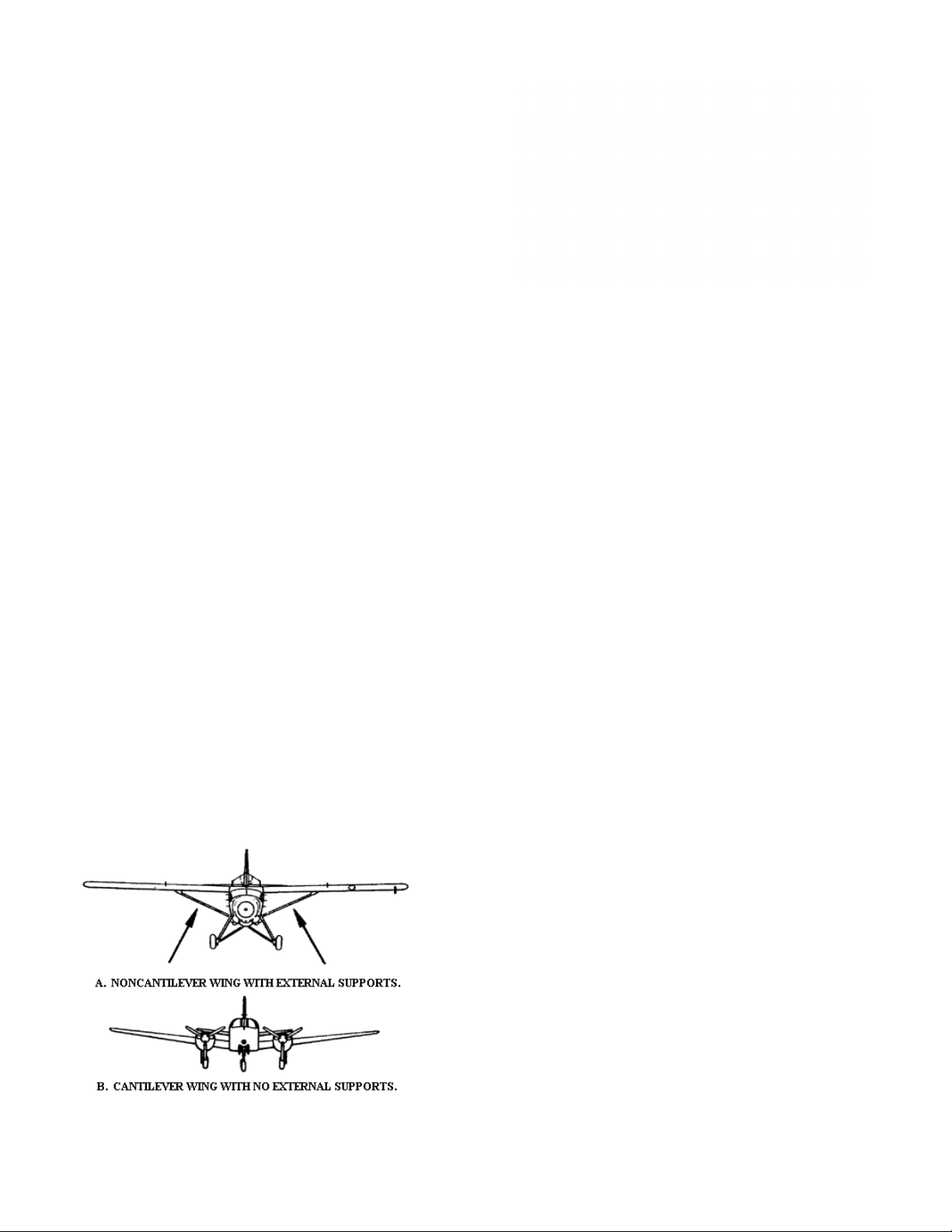
The prolific and successful high-wing design has a
number of virtues: it is easier to design and build a wing
which does not have to support itself (non-cantilever),
but which may be held up with struts attached to the
wings and the bottom of the fuselage. The high- wing
A real Piper J-3 “Cub”
1948 Stinson 108-2
1947 Luscombe 8a Silvaire
1948 Taylorcraft BC-12d
1950 Aeronca 7AC Champ
www.a2asimulations.com CHERO KEE 180 MAN UAL
:::
A2ASIMULATIONS
7

AN AEROPLANE FOR THE REST OF US
Left: 1947 Cessna
190 showing
an unusual
cantilever
high wing
design was also the choice of most GA aircra manufacturers because a strut- braced wing is economical to
build being that it is lighter, thinner, and requires fewer
parts than a cantilever wing. Except for aeroplanes like
the Cessna 190/195 models, the Helio Courier STOL
(short take-o and landing), and the Dornier Do. 27/28,
high-wing aeroplanes of the 50’s were virtually all strut
braced.
Of course, the struts themselves add back some the
weight savings of a non-cantilever high wing and additionally impose a drag penalty which the cantilever wing
design, requiring no support struts, does not. However,
while more aerodynamically clean, the weight penalty
of the heavier and bulkier cantilever wing may be as
great a detriment in its way to overall aircra performance as is the drag coeicient produced by wing support struts. Properly designed, a wing strut’s production of drag may be minimised. Aside from economical
concerns, another of the virtues of a high-wing design is
that the pilot’s and passengers’ are granted an almost
unobstructed view of the ground during flight. In addition, for purposes of visual navigational orientation as
well as for sightseeing, a high wing gives good service.
Today, and since the introduction of the Cherokee
series of aircra in 1961, Piper Aircra has come to be
known as a manufacturer of mostly low- wing GA aeroplanes, the PA-18-150 Super Cub being the lone exception. However, for 24 years, from its founding in 1930,
when businessman and oil speculator William T. Piper
purchased the assets of the bankrupt Taylor Aircra
Company for $761.00, except for a small number of
interesting Piper low-wing prototypes along the way
(PT-1 Trainer-1942, PA-7 Skycoupe-1944, PA-6 Skysedan-1945, and PA-8 Skycycle-1945, none of which went
into production), Piper Aviation had exclusively produced high- wing aircra until the twin-engine PA-23
Apache in 1954. The Taylor/Piper Cub and its progeny,
the PA-15/17 Vagabond, the PA-16 Clipper, PA-18 Super
Cub and the PA-20 Pacer with its variants including the
revolutionary tricycle- undercarriage PA-22 Tri-Pacer
were all high- wing, fabric- covered aeroplanes. The PA22 Tri-Pacer which was introduced to the public as early
as February 1951 predated Cessna’s first tri-gear singles,
the 172 and 182 by five years.
Typical wing struts
1960 Piper Pa-18-150 Super Cub 1954 Piper PA- 23-150 Apache
8
A2ASIMULATIONS
:::
CHER OKEE 180 MAN UAL www.a2asimulations.com
Piper Pa-22-150 Tri-Pacer
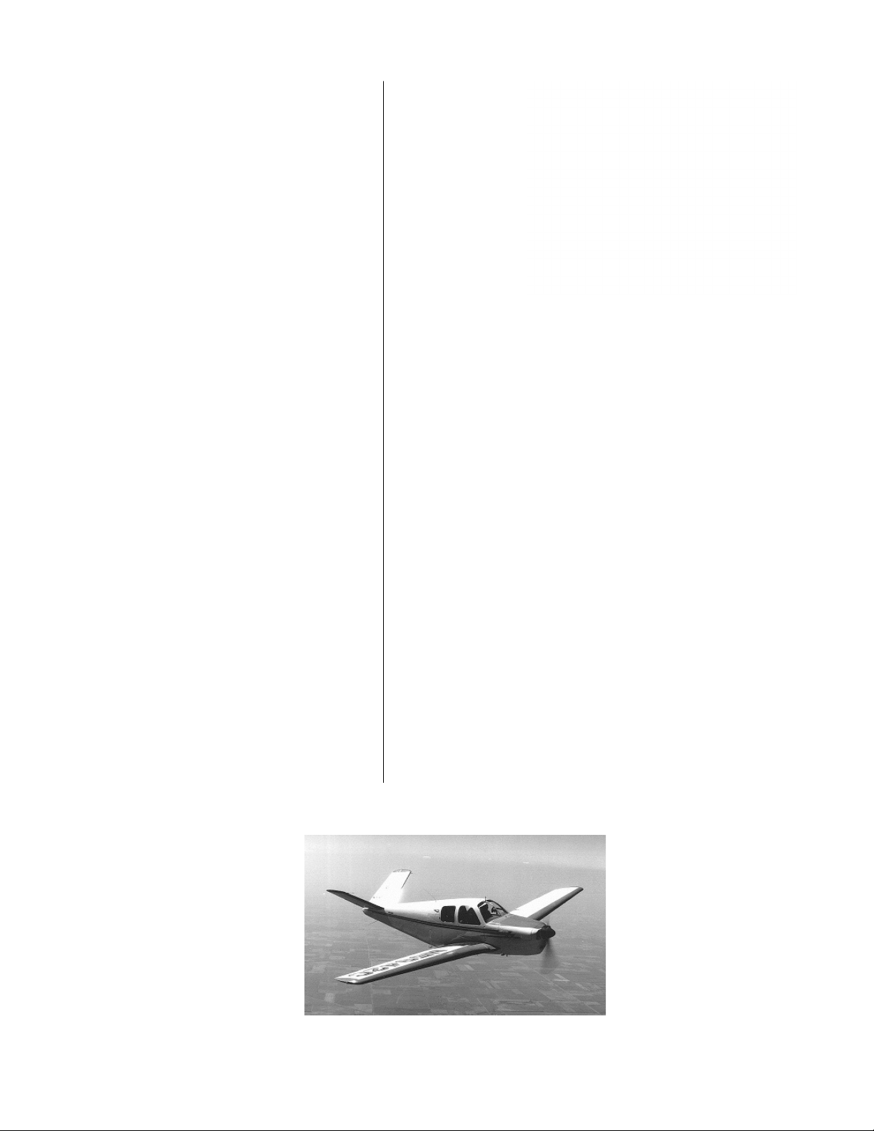
THE BONANZA BONANZA
Of course, amongst all of this GA high-wing high-jinx
there were a few exceptions with one very strong standout, the remarkably prescient Beechcra Bonanza
Model 35, designed in 1945 and introduced in 1947. Well
named, this aeroplane was a remarkable economic success for Beechcra, the first GA success story of the immediate post-war times. In fact, it was the enormously
positive response to the Bonanza in 1947 that fuelled
many GA aircra manufacturer’s starry-eyed optimism
and belief in the sales boom that never happened.
Designed by Ralph Harmon and his associates in
1945 as the war was coming to an end, Bonanza Model
35 had its first test flight on December 22, 1945. Incorporating what was then known of aerodynamics, aviation
technology and modern manufacturing techniques, its
clean, stressed skin (monocoque) all-metal structure
was reminiscent of the recently lionised Spitfires and
Mustangs and in many ways was a distinct departure
from previous GA aircra. With a retractable undercarriage, V-tail, seats for four adults, constant speed propeller and powered by a simple to manage and inexpensive to run six-cylinder, horizontally opposed, air cooled
165 hp Continental 0-470- E165 engine, it was the first
of a new breed.
In its class and for its time the Bonanza was the
epitome of aeronautical design and engineering — fast,
sturdy, and looking like nothing that had come before.
Sure, it was pricey at the then great sum of $7,975.00
($7,975.00 in 1947 had the same buying power as
$85,165.95 in 2013, annual inflation over this period
being 3.65%), but to its purchasers it was worth every
dime. Upon its introduction, corporations, businesses
and wealthy professionals placed almost 1,500 orders in
advance of its release making the Bonanza an unqualified and immediate roaring success.
While Cessna and many other manufacturers
seemed to be still tied to old, pre-war designs and concepts, Beechcra’s Bonanza was an entirely new breed,
a leap forward that looked like and in every way was
“the very model of a modern” aeroplane. Throughout
the 50’s the Bonanza’s sales continued to soar and its
place at the top of the food chain remained essentially
unchallenged.
1947 Beechcraft
Bonanza Model 35
instrument panel with
50’s style non- “T”
instrument layout and
early classic Narco
“Omnirange” VOR
receiver as almost an
afterthought. Note- no
ILS equipment and
30’s-40’s throwback
throw-over yoke system,
toe brakes only on left
rudder pedals.
Continental 0-470
1947 Beechcraft
Bonanza Model
35 3-view
1947 Beechcraft Bonanza Model 35
www.a2asimulations.com CHERO KEE 180 MAN UAL
:::
A2ASIMULATIONS
9

AN AEROPLANE FOR THE REST OF US
1958 Piper PA-24-250 Comanche with one piece windshield and aftermarket spinner
THE BONANZA KILLER
Most painfully cognizant of the Beechcra Bonanza’s
well-deserved success, by the end of the 1950s Piper
Aviation was anxious to produce its own modern, all
metal, retractable undercarriage, high performance single-engine aeroplane. Seeking to enter and to dominate
the high-performance GA business aeroplane market
and unseat the Bonanza, Piper Aviation made ready to
topple the King and to take its place on the GA high- performance throne.
To this end, Piper designed and developed the PA-24
Comanche, “The Bonanza Killer”. Piper Aircra’s ambitious intent was to not only put an end to the Bonanza’s
long- held high-performance single- engine commercial
reign, but to put Piper firmly on the map as GAs leading
and most advanced aircra manufacturer. Piper knew
that to do all of this would require an exceptional aeroplane, one that performed to the highest standards,
was fast, comfortable and safe. Of all, this last requirement was key.
Piper Aviation has traditionally leaned heavily towards flight safety in its designs. Gentle and predicable
stall characteristics, inter-connected rudder and ailerons to prevent inadvertent spins on some models,
slow landing speeds and the like had been regularly
and scrupulously designed into Piper aircra from the
beginning. Accordingly, by the mid 1950s Piper had not
been historically known for producing fast, all-metal,
high-performance aircra; but all that was going to dramatically change before the decade was out.
TAKING THE LOW (WING) ROAD
TO SLAY THE KING
William T. Piper knew that in seeking to enter the highperformance, single-engine business aeroplane market
and challenging the iconic Bonanza that he was he was
taking on a very tough, commercially risky task.
By January 1958 the first Piper PA-24-180-Comanche
was delivered to the public. Its cruising speed at 75%
1960 Piper PA-24-250 Comanche instrument panel with 50’s style
non- “T” instrument layout. As in contemporary Bonanza, radios
seem to be almost an afterthought. Note- modern-style VOR but
no ILS equipment, dual controls but toe brakes on only left rudder
pedals, large ap handle but no Johnson bar brake handle.
1964 Piper PA-24250 Comanche with
unpainted spinner,
aftermarket onepiece windshield
and tip-tanks
1967 Piper PA-24250 Comanche with
3-blade propeller,
aftermarket
spinner, onepiece windshield
and tip-tanks
1959 Piper PA24-250 Comanche
Note- tail low
ground stance,
large nose wheel
and short main
undercarriage legs.
10
A2ASIMULATIONS
:::
CHER OKEE 180 MAN UAL www.a2asimulations.com

at 8,000’ is 139 knots (159.85 mph) which in its day was
excellent for a four-seat, 180 hp aeroplane, but not quite
fast enough to seriously compete with the 165 knot
(189.75 mph) 240 hp Bonanza 35H at 75% power.
The first low-wing GA aeroplane produced in over a
decade, the Comanche was something new and exciting. A breathtakingly beautiful design, its novel sweptback tail, its gracefully tapering wings and sleek fuselage gave it the look of innovative modernity in the
same way that Lancaire and the Cirrus aircra appear
to us today.
Accordingly, Piper began to immediately test the
installation of a 250 hp Lycoming O-540 engine in the
Comanche. The PA-24-250, introduced in April 1958 has
a very competitive 75% cruise speed at 8,000’ of 160
knots (184 mph).
So, did the Comanche actually kill the Bonanza?
Well, the answer is clearly, no. However, it did compete
well with it and better in that regard than anything else
in its time. Piper and Beechcra continued to strive
with each other until the Comanche suddenly ceased
production in 1972, along with the excellent, sleek and
speedy Twin-Comanche, as a result of catastrophic
damage to Piper’s Lock Haven, PA factory caused by
the record rising of the nearby Susquehanna River due
to Hurricane Agnes. Today, as newer and even sleeker
modern composite designs vie with it for top dog in the
GA high-performance, single- engine market the Bonanza lives on, albeit in the shape (if not the name) of
the venerable, conventional tail Debonaire, and is still
in production with no end in sight.
While its time in the market as a new aeroplane
was relatively short (1958-72), since its introduction
the Piper Comanche has been and still is one the most
highly- respected and desirable GA aeroplanes. A good
one in good condition is considered a prime find on the
used aircra market. Today there are many thousands
of loyal Comanche adherents who firmly believe, and
with good reason, that it is the most beautiful, elegant
and overall best performing single-engine GA aeroplane
ever built. Right, Scott?
Second test
proto-type of
Piper PA-24-180
Comanche
1958 Beechcraft
Bonanza H35
with tip-tanks
1959 Beechcraft
Bonanza 35J
Lycoming 0-360
Piper PA-24- 250 all original contemporary Beechcraft Bonanza G36Piper PA-30- 160 Twin Comanche - R. I. P.
www.a2asimulations.com CHERO KEE 180 MAN UAL
:::
A2ASIMULATIONS
11
AN AEROPLANE FOR THE REST OF US
HOW ABOUT AN AEROPLANE
FOR THE REST OF US?
Without any question, the Bonanza and the Comanche
were and are very high performance single-engine GA air
cra aimed at distinctly well-heeled potential private/corporate owners. However, there also existed a significant
segment of the GA market that wished to own a new, rea
sonably fast (if not the fastest), modern, all-metal, fourseat aeroplane, but who could not aord the Comanche’s
and especially the Bonanza’s high price tag. FBOs (fixedbase operators), flight school operators and flying clubs
were also looking for aircra that they could rent out at
rates that the average weekend private pilot could aord.
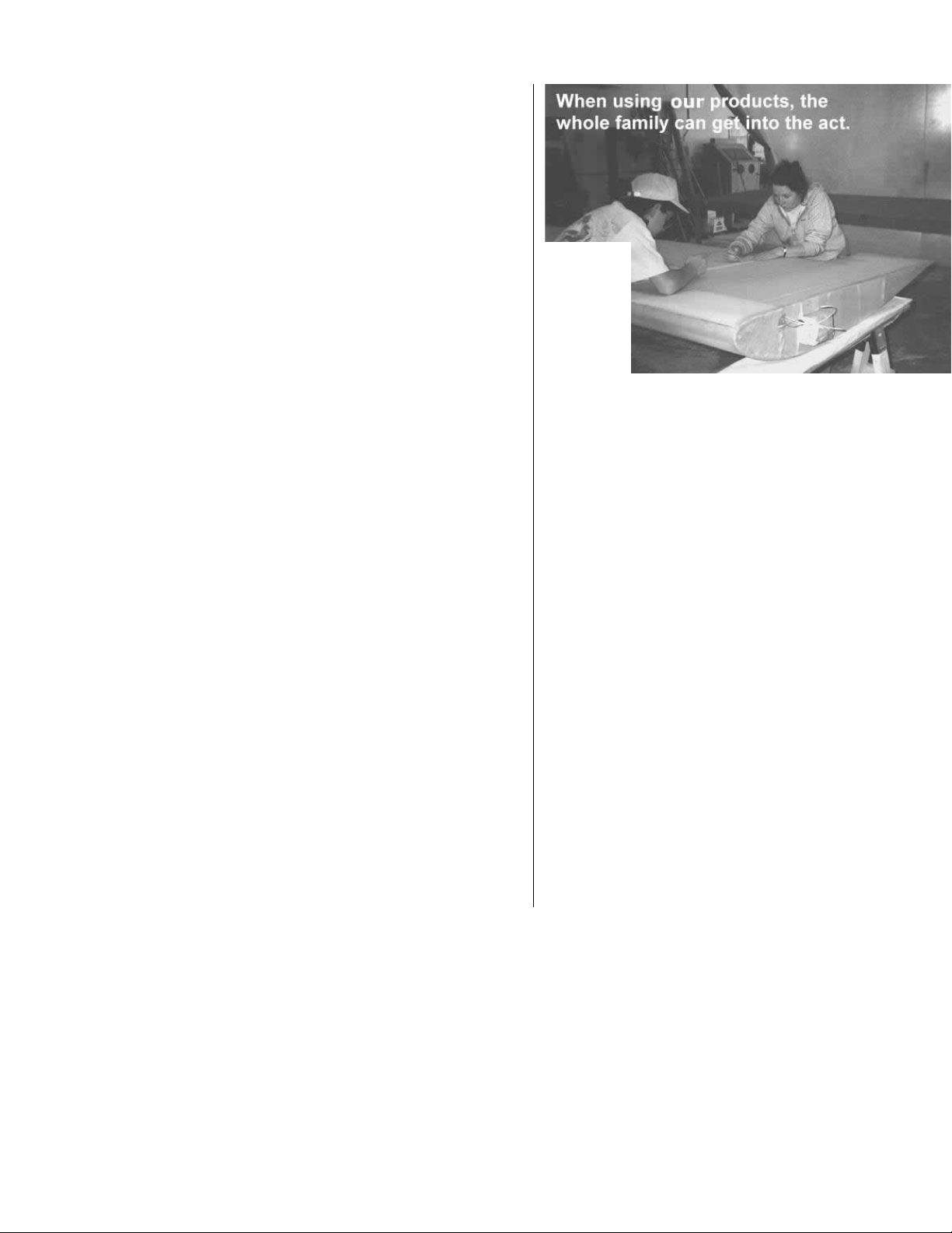
As the prosperous second half of the 1950s came to a
close, Piper understood that the time of the fabric- covered Tri-Pacer and Colt had come to its end. Studies within Piper Aviation in the mid- 50’s showed that with modern manufacturing techniques it was actually now more
cost-eective to produce an all-metal aeroplane than to
continue to produce the old school parts and labour- intensive, metal frame, fabric- covered Tri-Pacer and Colt.
Even with plans to build the Comanche already
drawn, the factory tooling up to manufacture it, and
with Piper’s well-founded hopes and expectations that
its new beauty would well-establish Piper Aviation in
the high-performance single-engine, business aeroplane market, William T. Piper knew that if Piper was going to survive and flourish into the next decade and beyond that, further aeronautical invention and progress
was wanted. He, his son Pug and the entire Piper team
knew that they had to produce a new, modern entry to
mid-market level aeroplane as soon as possible in order
to compete with Piper’s true rival, the only other major
aircra company that was actively and successfully servicing that segment of the GA market, Cessna.
Immediately upon the introduction of the all- metal
Cessna 172 in 1956 Piper knew that its internal evaluations regarding the obsolescence of fabric-covered aircra were indeed valid and that their then single-engine
star, the Tri-Pacer, had already been eclipsed. While the
exceptional Comanche had, in fact, turned out to be
highly competitive in the high-end GA niche, giving the
equally exceptional Beechcra Bonanza a good run for
the money, Piper well understood that in order to compete in and command a viable position in the entry/
middle price market it needed to oer something new,
-
-
Rib- stitching a
fabric covered
Tri-Pacer’s
wing before
doping —
one of this
process’s
many labourintensive steps.
something that would give potential owners an attractive alternative to Cessna’s popular 172.
Looking to produce a four-seat design which would
be simpler and which could be produced less expensively than the complex, retractable gear, constant- speed
propeller Comanche, Piper also knew that in order to be
competitive in the lucrative trainer market they needed
to build a replacement for the two- seat Colt which had
been commercially greatly overtaken by the all metal
Cessna 150. If these two needs could be resolved by one
overall design, so much the better.
A product of the prosperity and economic confidence
of the late ‘50’s in the United States was a wave of new
student pilots. Flight schools and clubs were popping
up at virtually every local airport and business was very
brisk. Since its introduction in 1958, the all-metal, twoseat Cessna 150 had become by far the most popular
aircra in this burgeoning trainer market. As the last of
the J-3’s, Aeronca Champs and other similar tail-wheel
(then called “conventional undercarriage”) aircra
began to disappear from attrition mostly due to tailwheel induced taxiing and landing accidents, they were
quickly being replaced by the tricycle undercarriage 100
hp Cessna 150 and, to Piper’s disappointment, to a far
lesser extent the 108 hp, two seat version of the old TriPacer, the fabric- covered Piper Colt. It was understood
that the old tail- wheel trainers did not oer as relevant
a training experience to student pilots who looked for-
12
1961 Cessna 172
A2ASIMULATIONS
1959 Cessna 150
1960 Piper PA-22-108 Colt
:::
CHER OKEE 180 MAN UAL www.a2asimulations.com

1956 Cessna 172
1956 Cessna 172 interior
ward to soon flying higher performance aircra, all of
which had tricycle undercarriages.
Also, unlike the J-3, etc. where the student and instructor sit in tandem, in the new trainers the instructor and
student sit side- by- side, facilitating communication as
well as increasing the confidence of the student and mak
ing it easier for the instructor to demonstrate maneouvers
and to teach the lesson. Additionally, and most signifi
cantly for FBOs, flight schools and clubs, with the advent
of these new tricycle- undercarriage trainers, ground
loops and nose overs whilst landing as well as collisions
whilst taxiing became a thing of the un- mourned for past.
The Tri-Pacer shared the same market as Cessna’s
172; however, except that they were both high-wing,
four place aeroplanes of similar power, they actually
shared few similarities, particularly with regard to construction and appearance.
Firstly, the Tri-Pacer was fabric covered whilst the
172 was all metal. The higher maintenance cost of a
fabric covering as well as the anticipated expense of an
inevitable fabric re-covering was a strong market motivator toward the all- metal l72.
Secondly, the Tri-Pacer’s frame has many steel components within which can and do rust, and eventually cause
major repair headaches. The 172’s stressed-skin covered
airframe is sturdy, low- maintenance and is all aluminium.
Thirdly, the Tri-Pacer, which had been introduced
in 1951 was distinctly showing its age and was, in fact,
something of an anachronism by the beginning of the
following decade. Its foreshortened appearance gave it
a somewhat stodgy look and sitting seemingly precariously upon its closely spaced undercarriage, it garnered
the unfortunate nickname “Flying Milk Stool”. Piper
-
had to face it; the Tri-Pacer just didn’t imply a clear and
definite sense of modernity as surely as the Cessna 172.
-
Taking everything into consideration, Piper saw the
writing on the wall.
Ironically, the Tri-Pacer’s performance is excellent,
competing well with and in some instances beating the
newer Cessna 172. The 160 hp Tri-Pacer climbs at approximately 800 fpm loaded at or near MGW with a top speed
of 123 k (141.5 mph) and a 75% cruise of 117k (134.5 mph)
at 7,500’. Its useful load is 890 lbs., and its take-o and
landing performance as well as its slow and departed
flight performance is overall better than the 172’s. The
Tri-Pacer is more responsive than the Cessna 172 and
many pilots have found it to be more fun to fly. Nevertheless, by the end of the 1950’s the more modern-looking
Cessna 172 was running away with the middle GA market.
Before 1961 one might well be excused for thinking
that with the exception of the low-wing twin-engine
Apache, the Comanche and the Pawnee crop-duster
that Piper leaned heavily towards the production of
high-wing aeroplanes. Aer three decades and thousands of fabric-covered, high- wing Pipers this trend
changed dramatically, marking the end of one era and
1959 Piper PA22-150 Tri-Pacer
www.a2asimulations.com CHERO KEE 180 MAN UAL
1967 Cessna 172/Skyhawk
1960 Piper PA-25-235
Pawnee crop duster
:::
A2ASIMULATIONS
13
AN AEROPLANE FOR THE REST OF US
Left: Fred Weick’s
brilliant and
innovative 1936
Erco 315CD
“Ercoupe”
Center: Very
rare photograph
of experimental
retractable
Ercoupe
Right: Fred
Weick with his
Ercoupe Noteconstant speed
propeller with
anti- icing boots
the beginning of a new one when the first of the all metal low-wing PA-28-150 and PA-28-160 Cherokees were
introduced to replace the Tri-Pacer and the Colt which
were then withdrawn from production.
CREATING AN AFFORDABLE LEGEND
In 1957, Karl Bergey, Assistant Chief Engineer at Piper’s
brand new Vero Beach facility which was built to design,
test and ultimately manufacture the Cherokee, led the
team of engineers and designers whose task it was to
create an aeroplane that would establish the new, modern Piper Aviation in the present and secure it well into
the future. Pug Piper sought to create a small team of
engineer/designers who had reputations for having the
foresight and imagination to create something new. To
that end, Pug Piper’s friend, the talented, progressive
and imaginative 1928 Collier Trophy winner, Fred Weick
was invited to join the team.
Weick was one of the first American aeronautical engineers who had, among other things, worked closely with
the United States Postal Service in the early 1920s to establish and to develop the U.S. Air Mail Service. In 1925,
whilst an engineer working for the National Advisory
Committee for Aeronautics (NACA), Weick was the chief
design engineer and responsible for developing streamlined cowlings to improve aerodynamic eiciency while
enhancing engine temperature control. He also helped to
design the first full-scale propeller wind tunnel.
By 1936, as chief designer at ERCO, Mr. Weick designed the revolutionary ERCO 310, better known as the
“Ercoupe”, designed to be virtually stall and spin-proof
with integrated rudder and aileron controls (no rudder
pedals), a crosswind resistant undercarriage, and one of
the first aeroplanes designed with a tricycle undercarriage.
Both William Piper and his son, Pug greatly admired
the extraordinary talents of the brilliant and prolific
aeronautical engineer/designer John W. Thorp who
agreed to join the team. In the course of creating the
Cherokee this stellar design team found Thorpe’s keen
aeronautical mind to be a great and powerful resource.
The design of the Cherokee ultimately greatly benefited
from many of John Thope’s ideas and from his excellent
past designs. In particular, the team incorporated many
features from Thorp’s amazingly ahead of its time, the
1945 all- metal T-211.
A MOST DELICIOUS WING
The first thing that Pug Piper told his team was that the
new aeroplane would have a low wing for a new Piper
look and so that drag producing struts of any kind could
be avoided. He wanted Piper Aviation to build on the
excellent reputation that the low-wing Comanche had
already established and envisioned an aeroplane that
would look and be as entirely dierent from the Cessna
172 as possible.
John W. Thorp
14
A2ASIMULATIONS
1945(!) Thorp “Skyshooter” T211 showing the true
genesis of the Cherokee design. Note the Hershey
Bar wing, undercarriage conguration, corrugated
skin rudder and the stabilator with anti-servo tab.
:::
CHER OKEE 180 MAN UAL www.a2asimulations.com

An all metal, cantilever 160 sq. . (15.14 m), 30’ (9.2
m) span, 5’ 3” (1.6m) constant-chord (non-tapering)
wing, popularly called the “Hershey Bar” wing because
of its similarity in shape to that most famous rectangular confection, became the basic platform upon which
this new aeroplane was built. This wing’s aspect ratio
(span divided by chord) is on the low side at 5.63. This
was not a problem or a new situation at Piper. The immediate predecessors of the Cherokee, the so- called
“short wing” Pipers, the Vagabond, the Clipper, the Pacer, the Tri-Pacer and the Colt which the Cherokee series
of aircra was to replace had even lower aspect ratios.
By comparison Cessna 172’s aspect ratio was 7.448.
It was a deliberate design choice to raise the new
Cherokee’s wing’s aspect ratio a bit from the shortwinged Pipers in order to increase its Cl (coeicient of li)
and thereby its eiciency. Up to a point, a higher aspect
ratio wing promotes better high altitude cruise, climb
and glide performance. However, a wing with a lower aspect ratio has at least one advantage — it has a higher
critical angle of attack (Alpha), i.e., the positive Alpha
at which it will stall; additionally the stall itself tends to
be gentle. The old short-wing Pipers were not very eicient power-o gliders (I recall that the Colt, particularly,
glided like a stone); however, they were extremely forgiving at low airspeeds and in extreme departed flight attitudes. They could, with suicient power applied, seem to
“hang on their propellers” with their noses sitting way up
in the air whilst flying at very low airspeeds. It had been
Fred Weick’s lifelong goal to build aeroplanes such as the
Ercoupe that were easy to fly and by extension, safe. All
agreed that forgiving flight characteristics would be a
most attractive feature to the low-time pilots and FBOs
that were Pipers commercial target.
The team designed the Cherokee’s wing to be
mounted at an angle of +2º to the fuselage’s longitudinal datum line in order to permit a distinctly nose-down
attitude, thus promoting good forward visibility for the
aeroplane’s occupants on the ground and in flight, and
Aspect Ratio - wing
span (tip to tip) divided
by average chord
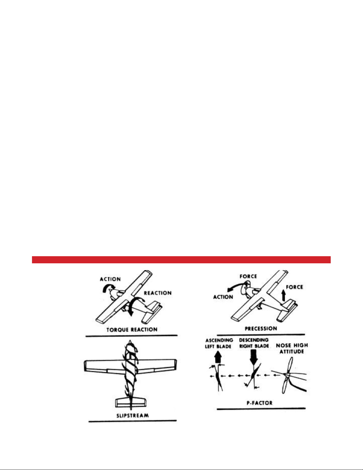
reducing P-eect (combination of twisting slipstream*
and induced propeller yaw in the opposite direction of
the turning of the propeller when at positive Alpha) during the takeo run. They wanted to improve upon the
Comanche’s distinctly nose-high stance on the ground
which creates a good deal of P-eect on takeo requiring lots of right rudder to keep it on the centreline.
*For what it’s worth, this writer does not hold very
much with the theory of a twisting slipstream as a major
P-eect force for a number of reasons to lengthy to go
into here. Also, remember, P-eect operates in the yaw
axis, torque in the roll axis.
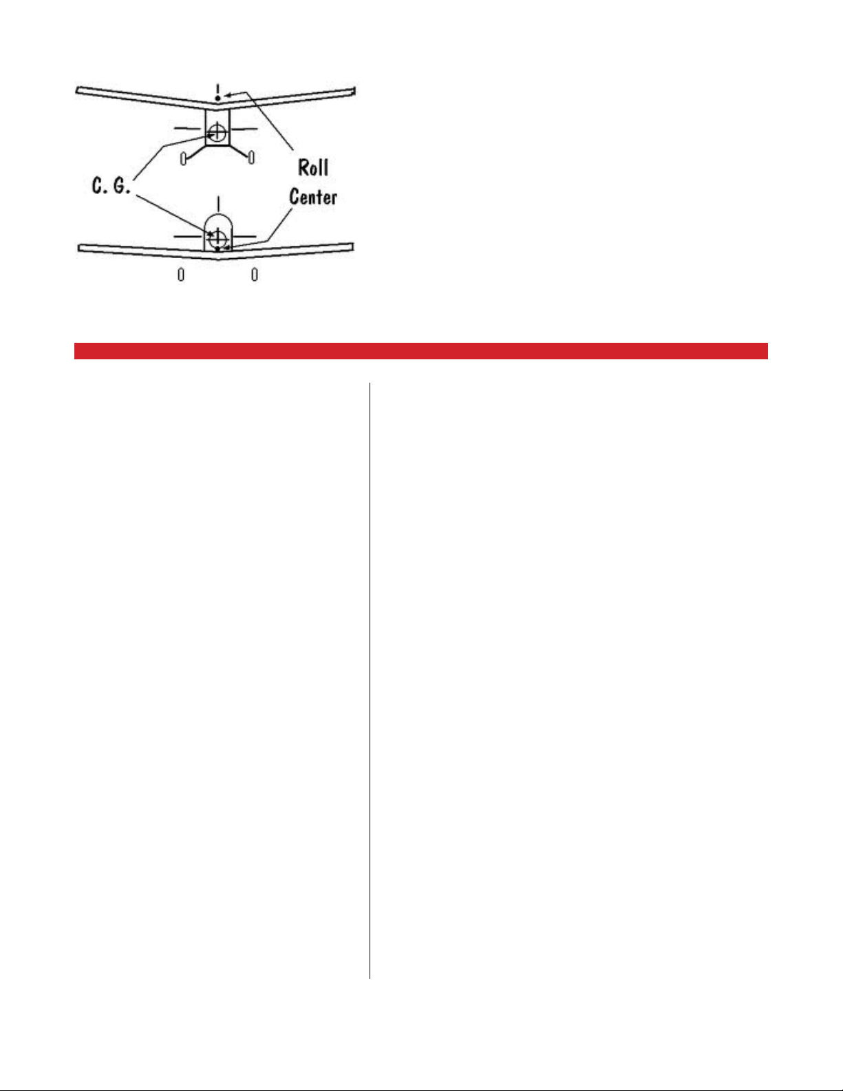
Being a low-wing aeroplane, the Cherokee’s overall
vertical centre of gravity (C.G. v) is low, however, it is
necessarily at a point above its low wing. This promotes
poor stability in the lateral (roll) axis while enhancing
maneouverability. While enhanced maneouverability is a good thing in a fighter, aerobatic show or sport
aeroplane, it is not necessarily so good in an aeroplane
Left to right:
1) Piper PA-16
Clipper
2) Piper PA- 17
Vagabond
3) Piper PA-22
Pacer (Tri-Pacer
in red above)
4)1964 Piper
PA-28-140
showing original
“Hershey Bar”
rectangular wing
www.a2asimulations.com CHERO KEE 180 MAN UAL
:::
A2ASIMULATIONS
15
AN AEROPLANE FOR THE REST OF US
Angle of Attack (AOA) also called “Alpha”
16
A2ASIMULATIONS
P (propeller) -Effect
:::
CHER OKEE 180 MAN UAL www.a2asimulations.com
Hershey Bar Cherokee showing 7 degrees of dihedral
Cessna 172 showing 3.5 degrees dihedral
designed to be used for training new pilots and for comfortable and easy touring. To create good lateral stability a low- wing aeroplane requires dihedral, more dihedral than is required for a high wing aeroplane. Also, a
low wing aeroplane requires greater dihedral to provide
for adequate wingtip clearance when on the ground
and when a wing may be lowered during a cross-wind
landing. Accordingly, the Cherokee’s low wing has 7º of
dihedral which gives it very good lateral stability which
is especially welcome on long trips and when in mildly
turbulent conditions.
The vertical centre of gravity (C.G. v) of a high-wing
aeroplane is also low, but at a point below the wing
which promotes good stability in the lateral axis. This
means that less dihedral is required for high-wing aeroplanes. Accordingly, the high wing Cessna 172’s dihedral
is only 3.5º.
Dihedral causes a self-levelling force to occur when
the aeroplane is displaced from level in the roll axis. As
any force, such as turbulence, begins to roll an aeroplane from level, the downward moving wing’s Alpha
increases, creating li. In addition, the lowered wing assumes a more horizontal attitude than the higher wing
and, concurrently, the lower wing creates more li because of this, as well. Both of these eects tend to roll
the aeroplane back towards level.
Of course, too much dihedral can lead to a reduced
roll rate as well as over-sensitivity in turbulence, making for an uncomfortable ride in all but the calmest air.
Compensating for its generous dihedral, the rectangular wing Cherokee’s large and most eective ailerons
produce a rapid roll rate which is faster than that of
most GA aeroplanes. This is due in part to the reduced
lateral damping eect of the low aspect- ratio, slightly
foreshortened Hershey Bar wing. The Cessna 172’s
wingspan is 6’ greater than that of the rectangular wing
Cherokee and, accordingly, it creates more lateral axis
damping which somewhat reduces its roll rate. Accord-
www.a2asimulations.com CHERO KEE 180 MAN UAL
:::
A2ASIMULATIONS
17

AN AEROPLANE FOR THE REST OF US
ingly, the Cherokee is maneouverable, laterally stable
and rides quite well in all kinds of turbulent air. Accordingly, it seems that the Cherokee’s wing’s dihedral, like
so much else about this aeroplane, appears to be just
right.
Adverse yaw is the tendency for an aeroplane’s nose
to yaw in the opposite direction of bank and is caused
by the rising wing pulling back because of increased
induced drag created by li. To reduce adverse yaw,
virtually all modern aeroplanes, including the Cherokee, have ailerons which are dierentially rigged; that
is, there is more upward aileron movement than down,
causing there to be less li- induced drag in the rising
wing and thereby reducing its tendency to yaw the aeroplane away from the turn.
To simplify the Cherokee’s construction and to keep
costs to a minimum, a few new wing mounting techniques were incorporated. As mentioned, the Comanche’s le and right wings are joined in the middle in the
factory making the wing one piece. The entire wing is
then attached to the bottom of the fuselage, the main
spar being bolted to a receiving 3-sided box. This construction makes for a very strong +7g wing, perhaps
stronger than necessary in a non-aerobatic GA aeroplane. It is also quite costly. Piper’s team looked for another way to mount the wing to the fuselage that would
be strong enough but also simple and economical.
What they came up with is this: The Cherokee’s wings
are attached individually to each side of the fuselage.
Each of the Cherokee’s wings’ main spar is in the form of
an “I” beam which is inserted into to a box beam built as
a part of the fuselage frame located under the rear passenger’s seat, spanning the width of the fuselage. Once
the wings’ spars are seated within the box beam they
are secured with eight heavy bolts essentially making
the wing one piece. The inner ends of the forward and
a wing sub- spars are bolted to the fuselage through
matching mounting plates in the wing root and on the
fuselage. This greatly simplifies assembly as well as
making major wing repairs or replacement less expensive. An additional plus is that this method of mounting
the wings separately permits the use of a much shorter
shipping crate, thus saving transportation costs of the
unassembled airframe.
Piper reports that it has thoroughly tested the Cherokee’s wing mounting system, running at least 480,000
load and unload cycles with no damage to the wing
mounts.
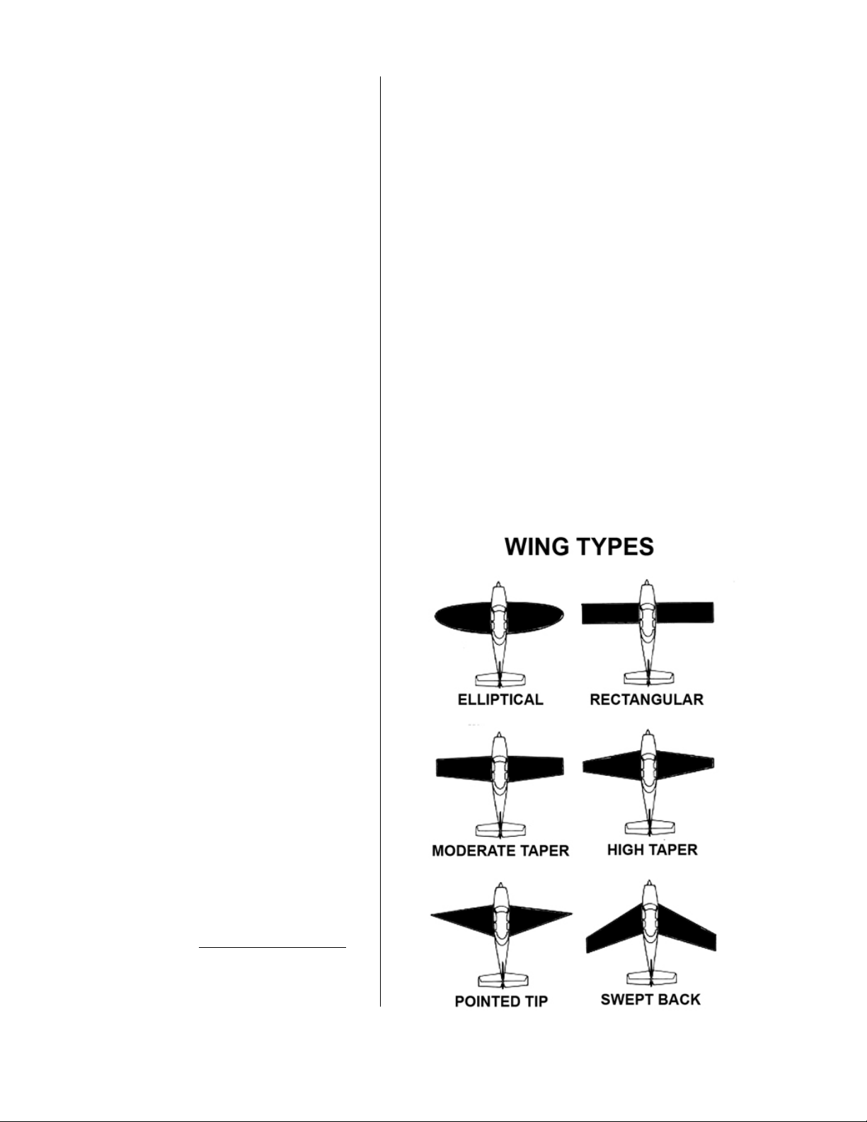
The Cherokee’s constant-chord, rectangular wing
planform did not, however, come about without some
friction and dissent within the design team. “Pug” Piper
wanted tapered wings as on the Comanche, both for
aesthetic and aerodynamic reasons. Both Thorp and
Bergey also initially thought that a tapered wing for
the new aeroplane would be best even though Thorp,
in particular, had been a long-time, outspoken advocate of non-tapered wings for GA aircra (see the Thorp
T-112).
Supermarine
Spitres showing
elliptical wings
18
A2ASIMULATIONS
:::
CHER OKEE 180 MAN UAL www.a2asimulations.com
The team considered a tapered wing for three basic
reasons:
At first, Karl Bergey was, as was his boss, Pug Piper,
in favour of a tapered wing for the new design which he
said more closely emulated the commonly accepted
ideal wing plan form, the ellipse, as found on R. J. Mitchell’s spectacular and beautiful Supermarine Spitfire.
Piper, Bergey and Thorp initially agreed that an elliptical wing produces less overall li-induced drag than a
rectangular wing and is quite eicient.
The second argument for a tapered wing was that
since the tapered outer part of the wing has a shorter
chord it has less overall area than the inner part of the
wing. This reduced wing area would cause less upward
bending pressure on the root of the wing when in flight
than if it the chord was constant to the tip. With less
bending to worry about, a simpler, lighter inner wing
structure could be designed.
The third and perhaps the most practical reason for
a tapered wing (from a marketing perspective at least)
was that they look sleek and aerodynamically “correct”.
Always most aware of the importance of marketing with
regard to of any commercial product, Pug Piper, as had
his father so many times before him, found this argument to be highly persuasive.
It looked like the Cherokee was going to have a tapered wing similar to the Comanche’s when Thorp began to advocate for a rectangular wing instead. Aer
ruminating about the issue for a while and he began to
discount the structural argument for a tapered wing. He
reasoned that the dierence in the structural weight of
a tapered verses rectangular wing of the same size was
too small to consider. Combining this with his aerodynamic analysis he said that aerodynamic scale eect
makes it possible to use a smaller rectangular wing
(rather than a larger tapered wing) for a given stalling
speed. He went on to explain that therefore the tapered
wing, though possibly inherently slightly lighter, must
ultimately be of greater span in order to provide equal
wing area to that of the un-tapered wing, thereby erasing any weight saving.
As to the elliptical wing planform theory, Thorp rejoined Piper and Bergey’s opinions and held that there
was more to the issue than that so- called “ideal”.
He argued that while the total of aerodynamic forces
indeed seemed to favour an elliptical wing form, where
the wing’s chord was shorter near and at the tip of such
a wing, or in any tapered wing seeking to emulate an
elliptical form, the Reynolds Number (RN)* is similarly
lower near and at the wing tip, therefore causing a great
propensity for the wing tip to stall before the rest of the
wing.
Reynolds Number =
V(speed) x L (length of chord)
Kv (kinematic viscosity)
“stickiness” of the air. For simplicity you can use the
value 6327 for the Kv of air at the standard temperature
of 59 degrees Fahrenheit at Sea Level. The speed value
is in feet per second and the length is the chord of the
wing in linear feet.
The Reynolds Number is an essential measurement
of wing/aircra performance and if you are a serious
student of aerodynamics you will want to know a good
deal about it.
The others recognized Thorp’s argument to be sound
because, as is well-known, where the RN is lower the
maximum Cl is necessarily lower, creating less li at
any given airspeed as compared to any other part of the
wing where the chord is longer. Accordingly, it follows
that where the maximum Cl is smaller, that part of the
wing must stall first.
Thorp further argued that the relatively small size
of GA aircra’s wings and their relatively slow takeo
and landing speeds exacerbates the tip stall problem
in a tapered or elliptical wing as the outer wing’s RN is
therefore even lower. Additionally, a tapered or elliptical wing is more readily likely to have reduced aileron
eectiveness. While it makes sense that the aileron on
a tapered wing may be less eective being mounted
at the tapered portion of the wing which has a shorter
chord and thus a lower RN causing lower eiciency and
Without getting too deep into the math of this for-
mula, the kinematic viscosity (Kv) is a measure of the
www.a2asimulations.com CHERO KEE 180 MAN UAL
:::
A2ASIMULATIONS
19
AN AEROPLANE FOR THE REST OF US
Some xes
for tip stall
a lower maximum Cl; it is also true that the tapered
wing’s outer section produces less aerodynamic lateral
damping force in a roll than does a constant chord wing.
Therefore, all else being equal, with properly designed
ailerons a tapered wing could have as fast or a faster
rate of roll than a constant chord wing of identical area
and span.
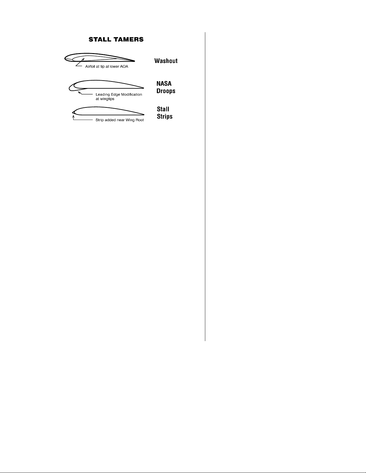
As a tapered wing for the Cherokee was being seriously discussed, the various known “fixes” for tip stall
were considered. The commonest of these is wing twist
or “washout” where the outer portion of the wing’s trailing edge is built to ride slightly higher than the leading
edge (producing lower local static Alpha). Additional
preventative measures for tip stall are aerodynamic devices which are attached and/or added to the wing such
as drooped or enlarged leading edges, stall strip at leading edge, more greatly cambered (curved) outer- wing
airfoil sections, fixed or automatic leading edge slots or
slats, and downward curved wing tips.
While these fixes do help the problem to some degree, they all add complexity, and/or weight to the
wing and all produce additional airspeed- robbing drag
which tends to negate the advantage that the tapered
wing was supposed to deliver in the first place.
In final analysis, Thorp, Bergey and Weick (who ad-
Piper PA-28-161
showing semitapered wing
PA-28-181 Archer
showing semitapered wing
mired Thorp’s sound reasoning on the matter) agreed
that nothing of any value, especially airspeed, would be
gained by incorporating a tapered wing, and admitted
that, in fact, the tapered wing in its pure “unfixed” form
was more prone to tip stalls and spins. They agreed that
a rectangular wing with a few degrees of washout would
be as or more eicient as an elliptical or tapered wing
without any of the tapered wing’s attendant tip-stall
problems and without the complexity and additional
expense of building a more complicated tapered wing
structure.
The team finally agreed upon a rectangular, constant- chord, “Hershey Bar” wing for the Cherokee,
which indeed proved to possess a high degree of cruise
eiciency, near to ideal li distribution characteristics,
and which is highly stable at low airspeeds, near-stall,
stall and departed flight conditions.
Always seeking to improve the Cherokee, in 1969 an
extension of the wing span was proposed in order to improve load carrying ability and rate of climb. However,
preliminary tests showed that a longer wing would necessarily increase positive bending pressure on the wing
root and inboard wing structure requiring an entirely
new and more robust inner wing design which would
necessarily add to manufacturing costs. The idea was
tabled for the time being.
In 1973 Piper revisited the Cherokee’s wing design
and decided to go with the original idea of a tapered
wing. While Thorp and Weick’s original theories regarding tapered vs. rectangular wings were correct and had
been well-proved, much to the dismay of many within
and without Piper Aviation, a new, tapered wing was approved for the PA-28-150.
This aeroplane also incorporated a few other upgrades, improved wing fairing and seals and was renamed the PA-28-151 “Warrior”. Thereaer, if a Piper
aeroplane has a “1” as its last number, as in PA-28-151,
etc. it has a semi-tapered wing. The “Warrior” broke Piper’s tradition which began in 1954 with the twin engine
Apache of exclusively naming its aircra aer the English language names of Native American tribes, and began a new tradition of also naming aircra using words
such as “Tomahawk”, “Arrow”, “Archer”, “Papoose”, etc.
that closely suggested and alluded to that noble culture.
The new PA-28-151 was very similar to the old PA-28150, except for its tapered wing, which is actually only
tapered from the mid - span point to the tip on each side
and therefore ought to more properly be called “semitapered”. The new wing was also increased by 5’ in
span to make up for the decreased area of the tapered
20
A2ASIMULATIONS
:::
CHER OKEE 180 MAN UAL www.a2asimulations.com

section, as Thorp had said would be necessary. The increase in span raised this new wing’s aspect ratio to 6.66
from 5.63 and likewise slightly raised its Cl. The product
of the additional span is a slight gain in rate of climb and
high altitude cruise speed and a flatter power-o glide.
Some of these performance gains were initially credited solely to the new semi- tapered wing itself; but
upon closer inspection and analysis it was discovered
that they were at least partially, if not mostly due to the
improved wing/fuselage seals and fairing incorporated
in the PA-28-151. At the same time, the semi-tapered
wing’s increased aspect ratio, which in addition to its
said performance enhancements also reduces the eective range of Alpha at which the Cherokee may fly before
stalling. This causes the semi-taper wing Cherokee’s Alpha at the stall to be lower than that of the Cherokee
with a rectangular wing.
In 1976 the PA-28-180 was re-designed with a semitapered wing becoming the PA-28-181 “Archer”; and by
1979 all Piper single- engine aircra had received semitapered wings, all of them, accordingly, both gaining
and losing therefore as mentioned above.
As far as performance goes between the Cherokee
with a rectangular or semi-taper wing, all else being
equal and without wheel pants, from sea-level to approximately 6,000’ the rectangular wing is actually faster than the semi-tapered wing. However, as altitude increases past 6000’ the rectangular wing loses airspeed
more rapidly. As mentioned, the semi-taper wing Cherokee has a slightly better rate of climb and also a flatter
glide. Flatter glide is good in itself, but has a down side
in that the semi-tapered wing Cherokee is more sensitive to airspeed when landing than is the rectangular
wing. This means that if there is any amount of excess
airspeed at the flair, the semi-tapered wing tends to
float a while before touching down where the rectangular wing settles down more quickly and with less float.
Whatever the reasons may be, the semi-taper wing’s
performance increases are very slight. This writer, having flown both versions of Cherokees prefers the rectangular wing over the semi-tapered wing for its speed,
sprightlier handling and its excellent landing, low-airspeed and stall characteristics; or perhaps it’s also out
of a sense of tradition and nostalgia.
Hershey Bar vs. semi-tapered wings
FOILED AGAIN
Aer careful analysis, the team selected the rather thick
at 15% NACA 652-415 laminar-flow airfoil as it was highly eicient at the airspeeds and altitudes at which the
Cherokee was expected to cruise while still preserving
good low airspeed characteristics and a most gentle,
benign stall.
This airfoil is an NACA “6” series airfoil, has its area
of minimum pressure 50% of the chord from the leading
edge, maintains low drag at 0.2 above and below the li
coeicient of 0.4, has a maximum thickness of 15% of
the chord, a= 0.5 means that the airfoil maintains laminar flow over 50% of the chord.
Despite the NACA numbers, the Cherokee’s wing’s
thickest point is actually closer to 40% back from the
leading edge.
Just a quick word or two about airfoils and what a
“laminar flow airfoil” is. The wing’s airfoil is its crosssection shape from leading to trailing edge and is primarily and most importantly an air diverter*. Among
other things, the airfoil diverts the air through which an
aeroplane’s wing travels downwards at the wing’s trailing edge so that li may be generated (see Newton’s
Third Law of Motion). In order to do this the “boundary
layer”, which is the very thin, viscous layer of air closest
to the surface of the wing, must adhere to the wing and
not become turbulent or detach from the surface of the
wing. As long as the boundary layer adheres smoothly
and uninterruptedly to the surface of the wing, the wing
will continue to divert air downward at the trailing edge
and thereby produce li.
*There are many theories of li, some traditional,
some imaginative and seemingly intuitive. However, in
recent years most of the traditional theories have been
discredited as they were found to be flawed, entirely
improbable or simply wrong as aeronautical knowledge
and understanding has progressed. It is most likely that
there are numerous ways in which a wing produces li.
The airfoil as a downwash “air diverter” at the trailing
Cherokee wing
root without ap
or aileron, “wet
wing” fuel tank
removed (leading
edge facing left)
This is the
Cherokee’s airfoil
straight black
line- chord
curved grey line mid line or mean
camber line
www.a2asimulations.com CHERO KEE 180 MAN UAL
:::
A2ASIMULATIONS
21
AN AEROPLANE FOR THE REST OF US
edge is and has for many years been what this writer
thinks is the most probable correct theory. Of course,
the true scientific mind must always be open to new
facts and disclosures. This writer awaits with great interest what is yet to be discovered.
Also, a smooth and adherent boundary layer produces minimum pressure and/or parasite drag enabling
the aeroplane to fly faster for any given amount of power. Slight micro-turbulation in the boundary layer actually increases its adherence to the surface of the wing;
but, when this turbulation becomes more severe and
becomes a turbulent flow, li is reduced and pressure
drag increases. If this turbulence becomes too severe,
which typically happens at critical positive Alpha, the
turbulent boundary layer detaches from the surface
of the wing creating random eddies and vortices causing considerable parasite and pressure drag to be produced. Upon boundary layer flow separation from the
surface of the wing the former downward diverted air
flow ceases and, concurrently, the wing ceases to generate li. This is the “stall”. An airfoil designed to produce
maximum uninterrupted, adhesive boundary layer flow
at the surface of the wing and minimum drag is called a
“laminar flow airfoil”.
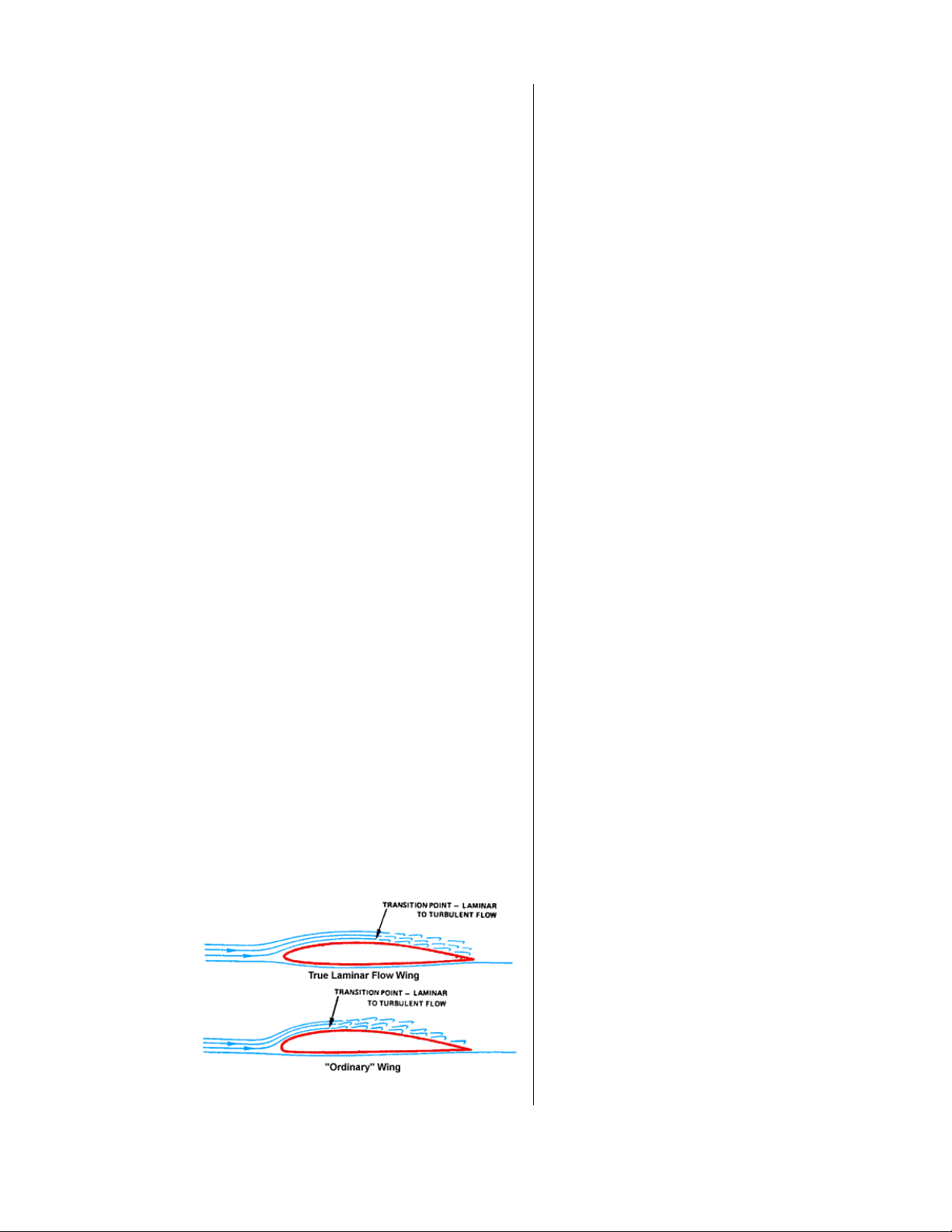
Laminar Flow
NACA NUMEROLOGY
The first number, “6”, of NACA 652-415 indicates that
this is a NACA “6-series” airfoil. The second number, “5”,
indicates the position in percentage x 10 of the chord
(leading to trailing edge) where minimum pressure occurs — here indicating the 50% chord position. Minimum pressure usually occurs at the thickest part of the
airfoil.
The subscript “2” indicates that this airfoil’s drag
coeicient approximates its minimum value between
plus or minus 0.2 of the airfoil’s design Cl. The NACA
65(9)-415 airfoil which is a later refinement of the NACA
652-415 has been used in the Cherokee as well, the only
dierence between it and the NACA 652-415 being that
in the latter airfoil the airfoil’s drag coeicient approximates its minimum value between plus or minus 0.9 of
the airfoil’s design li coeicient.
The number “4” indicates the li coeicient in
tenths; here, 0.4.
The last two numbers, “15”, indicate the wing’s maximum thickness as a percentage of the chord; here, 15%
of the chord.
A laminar flow airfoil is typically designed so that its
thickest point is usually at approximately 50% of the
chord. A normal airfoil’s thickest point is usually at approximately 25% to 33% of the chord. The laminar flow
airfoil shape combined with a very smooth wing surface
best promotes a smooth and adherent boundary layer.
The North American P-51 “Mustang” was the first mathematically designed aeroplane and its wing was the first
to be deliberately designed with a “laminar flow” airfoil,
however, even a very slight ripple or bump in or on the
surface of the wing can prevent the true laminar flow effect. Despite all good intentions the P-51’s wing surface
is not suiciently smooth and uninterrupted nor was
it optimally built or usually suiciently maintained in
the field to promote true laminar flow. The Cherokee’s
wing surface, however, is actually far smoother and if
kept scrupulously clean, promotes a stable, adherent
boundary layer very well.
A salient characteristic of the Cherokee’s airfoil is
that it has a fairly flat Cd (Coeicient of Drag) curve and
thereby looses li very slowly as the stall is approached.
Unlike many others, this airfoil does not possess a single
critical angle of attack (positive Alpha) at which it will
stall. The NACA 652-415 airfoil flies within a fairly broad
range of positive Alpha and does not break sharply at
the stall unless very aggressively forced into an extreme
positive Alpha condition called a “deep stall”. Spins
are likewise very diicult to enter unless aggressively
pursued. Additionally, the Hershey Bar wing’s low 5.63
aspect ratio helps to promote the Cherokee’s distinctly
anti-stall/spin behaviour. That these gentle stall/spin
characteristics were incorporated in the Cherokee’s design is no coincidence and very much in keeping with
Fred Weick’s life-long design practices, particularly with
regard to his Ercoupe design which, as mentioned, was
22
A2ASIMULATIONS
:::
CHER OKEE 180 MAN UAL www.a2asimulations.com
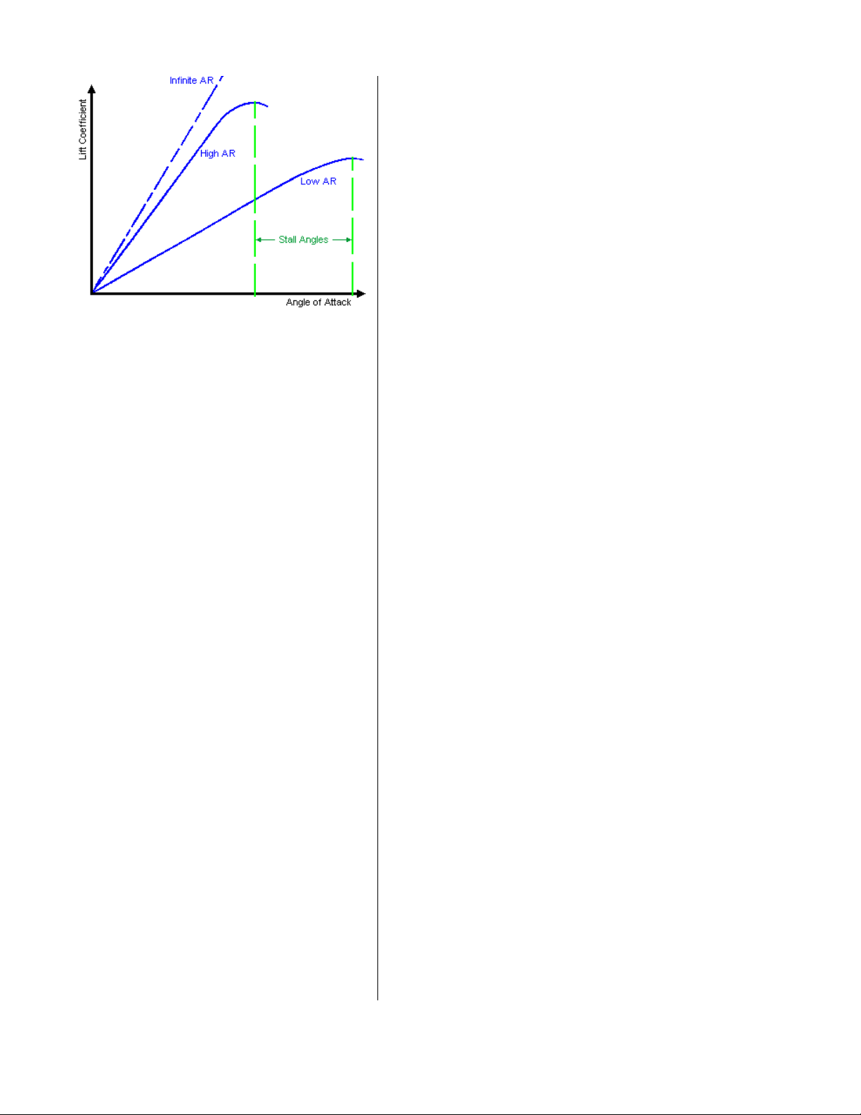
Simple Polar showing relative differences between
high and low aspect ratio wing (here - AR)
specifically designed to be virtually stall and spin-proof.
Those who have flown a Cherokee will surely attest
to its remarkably benign handling at low airspeed and
its reluctance to stall or spin. In fact, at one “g” with
power o it does not really break at all at the stall, but
merely oscillates gently forward and a while descending rapidly, which is the only indication that the wing
has in fact stalled. Pilots generally find the Cherokee to
be reluctant to stall with power on; although in this configuration the stall break may be a bit more definite with
the le wing falling due to engine torque at high power.
With power on the Cherokee rarely loses aileron control.
This is a sharp contrast to the Cessna 172 which loses
aileron control quite readily when near or at the stall.
These stall characteristics apply to both semi-tapered
and rectangular wing Cherokees, the rectangular wing
being the more benign and reluctant to stall due to its
higher Alpha before stall due to its lower aspect ratio.
Because the Cherokee’s NACA 652-415 laminar-flow
airfoil’s thickest point is near the wing’s mid-chord, approximately 40%, the main wing spar is located farther
a than is possible with non-laminar airfoils. Accordingly, as the main wing spar runs longitudinally across
the wing at its thickest point, its profile is deep and
great strength is gained therefrom. Also, the location
of the main spar so far a locates it under the rear passengers’ seat, permitting the cabin floor to be flat and
unobstructed.
surface is displaced and is more eicient than a conventional fixed stabiliser and hinged elevator. Accordingly,
it may be of less overall area than a similar conventional
fixed and hinged pitch control surface. Accordingly, the
early Cherokees’ stabilator was designed to be approximately two feet shorter in span than later ones making
these Cherokees with shorter stabilators slightly less effective in pitch control, particularly at slower airspeeds.
An anti-servo tab is located at the trailing edge of the
stabilator, similar to a trim tab; however an anti-servo
tab is mechanically linked to the stabilator to move in
the same direction as the stabilator when the stabilator is displaced by the pilot. This provides a proportional opposing force to the displaced stabilator, thus
avoiding negative aerodynamic stability (the tendency
of a balanced, moving, aerodynamic surface to deflect
further as it is displaced from neutral) and which, by
increasing the load on the stabilator as it is displaced,
prevents over- sensitivity in the pitch axis control system at all airspeeds.
In the Cherokee pitch trim is controlled by changing
the angle of the entire stabilator and anti-servo tab. At
the time that the Cherokee was being designed the allflying anti-servo stabilator was already a well-proved,
smooth and highly eicient pitch control system which
possessed the additional properties of being lighter
and, as mentioned, producing less overall drag than
Cherokee
showing
stabilator and
anti-servo tab
KEEPING THINGS STABLE
Following the successful Comanche design, instead of
the usual horizontal rear flight surface consisting of a
fixed stabilizer with a hinged elevator, the Cherokee incorporates a one piece, all- flying “stabilator” with an
anti-servo tab (also called an anti-balance tab) upon
which, not likely coincidentally, John Thorp holds the
patent. A one-piece (i.e. non-hinged), all moving stabilator pitch control surface produces less drag when the
www.a2asimulations.com CHERO KEE 180 MAN UAL
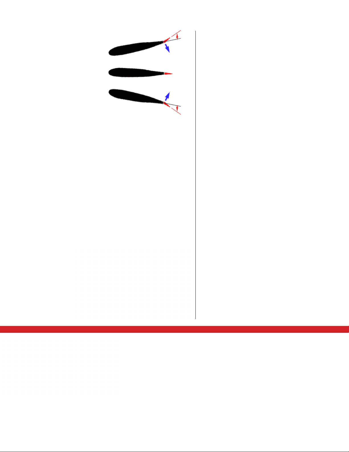
An antiservo
tab attempts
to streamline
the control
surface and is
used to make
the stabilator
less sensitive
by opposing the
force exerted
by the pilot.
:::
A2ASIMULATIONS
23
AN AEROPLANE FOR THE REST OF US
How a
stabilator with
anti-servo
tab works
the usual hinged stabilizer and elevator. A stabilator/
anti servo tab horizontal surface very similar to that
which was incorporated in the Cherokee appeared on
John Thorp’s 1945 T11 and T211. While Thorp’s original
design for the stabilator was innovative and eective,
it was also a bit complicated as to linkages and such.
Ever seeking to economise on production costs, Piper’s
Assistant Chief Engineer Karl Bergey modified Thorp’s
system and was able to simplify it while still bestowing
its essential benefits on the new aeroplane.
Speaking of pitch trim, early Cherokees followed
Piper’s unique method of elevator trim control, a horizontal hand-crank and position indicator located in the
ceiling between the front two seats. Tri-Pacers, Colts
and the first Comanches have the same control. It works
fine except that even though it is well-marked, many pilots (me too) have a devil of time remembering which
direction to turn the handle for up or down trim. BTW,
it’s clockwise for up and anti-clockwise for down.
SWEPT AWAY
We might as well get it out of the way here — the swept
back rudder and fin — does it serve any useful aerodynamic purpose as opposed to a straight tail or was it
merely intended to sweep customers o their feet with
a sweeping new design? (apologies)
Piper had incorporated a swept vertical tail on the
1958 Comanche, which this writer believes is the first time
such appeared on any mass-produced GA aeroplane. The
Beechcra Debonaire with its swept rudder and fin was not
introduced until 1960. Having innovated this feature, Piper
made it a priority to incorporate it as a signature design
on its next and subsequent Piper aeroplanes. In any event,
the aeroplane that Piper was most competitive in the GA
entry/middle market, the 1960 Cessna 172A, now had one.
In the late 50’s a swept vertical tail on a GA aeroplane was
new. It certainly looked modern and streamlined and sug
gested the tail surfaces of jet fighters and all. The marketing strategy went something like this: Everyone knows that
jet fighters go fast and that they have swept back surfaces;
so, if your Piper has a swept back rudder/fin similar to a
jet fighter, well then, it ought to go fast as well, right? Of
course, the swept surfaces on jet fighters have much to do
with trans-sonic and super-sonic flight which Comanches,
Cessnas and Cherokees, etc. have little to worry about. For
all of that did the swept rudder/fin on the Comanche, any
of the Cessnas or, more to the point, the Cherokee enable
any of them to fly faster? No, knot at all.
From a strictly aerodynamic perspective a sweptback rudder, its uppermost portion anyway, is located
slightly farther rearward than a straight rudder mounted
in the same position. This slightly moves the rudder’s CP
(centre of pressure) rearward and increases the uppermost part of the rudder’s moment arm which therefore
ought to increase its eectiveness to a small degree.
Others have postulated that the swept back fin/rudder is actually less eective and that it somewhat compromises directional stability and spin prevention. It
may be, however, that with regard to this it was an earlier straight- tailed 172 which was compared to a 1963 or
later swept-tail Cessna 172/Skyhawk with “Omni-Vision”
. If so, it is more likely that the cause of any perceived reduced rudder/fin ineectiveness, etc. was not necessarily the swept vertical surface but was actually the later
-
Piper PA-28-160 Cruiser showing
swept-back n and rudder 1967 Mooney M-20C Ranger 1962 Mooney M-20C Ranger
24
A2ASIMULATIONS
:::
CHER OKEE 180 MAN UAL www.a2asimulations.com

aircra’s cut - down rear fuselage which provides for the
“Omni-Vision” rear cabin window, and that the reduced
side area of the fuselage behind the C.G. is the real culprit for any directional stability or spin issues.
Also, if the aeroplane is banked a displaced sweptback rudder will tend to couple with both the aircra’s
pitch axis (as usual) and also positively to greater than
usual degree with the aircra’s roll axis. Accordingly, a
swept forward displaced rudder will couple negatively
with the aircra’s roll axis.
What a swept rudder/fin actually does as compared to a
straight one with regard to relatively low- speed GA aircra
might be able to be measured in a wind tunnel or by a very
sensitive set of in-flight instruments, but this writer is not
aware that any such study has been conducted. Having of
ten flown versions of the same aircra (C-172 and 182) with
both straight and swept tails this writer has not noticed any
appreciable dierence in the performance and handling
thereof that might be due solely to the rudder/fin configu
ration. Taking everything we know into consideration it
seems that a reasonable conclusion regarding this matter
is that the swept back rudder/fin on GA aeroplanes is noth
ing more than an eye- catching marketing tool which is, after all, still a legitimate reason for its existence.
One last, possibly definitive note on this subject; Al
Mooney ostensibly designed the Piper Comanche with
its swept back rudder/fin. However, all of his designs for
Mooney Aircra incorporate rudder/fins that famously
sweep forward.
COMFORT AND ECONOMY
Comfort: One of the important issues that Piper’s design
team had to consider was the creation of a new aeroplane that would cost far less to build and thereby be
able to be sold at a much lower price than the Comanche.
While the team considered that designing an aeroplane
that was less costly to build would not be so arduous a
task (Weick and Thorp had been designing inexpensive to
build aeroplanes for decades), simultaneously providing
the new aeroplane with a cabin as or more comfortable
than anything in its class was a bit more daunting.
Cabin size and particularly cabin width is a tricky
thing to consider when designing a small aeroplane. Every extra inch expands the frontal area and, accordingly,
increases parasite and form drag, resulting in a higher
Cd and reducing performance for available power
across a broad spectrum.
Piper’s target competition, the Cessna 172’s cabin is
a fairly cosy 39 ½” wide. This is a relatively tight fit for
full - sized adults, 1/2” narrower than Piper’s previous
single- engine flagship, the Tri-Pacer, with its snug 40”
cabin width. In years past this writer flew many pleasant
hours in Tri-Pacers and somehow does not remember
that it was such a tight fit; but then that was many years
ago and this writer was then, let’s say, a bit smaller.
The planned cabin width of the new aeroplane was
at first to be a generous 44”, the same width as their then
single-engine flagship, the Comanche. However, Piper
felt that its new, more economical aeroplane ought not
compete so closely with its flagship aeroplane and it
wanted to reserve to the Comanche just a bit more cabin comfort than its less expensive brother. Accordingly,
the Cherokee, as the new aeroplane was finally named,
would have a 40 1/2” wide cabin, still an inch wider than
its closest competitor, the Cessna 172.
Another way that the Cherokee was designed to
increase cabin space while keeping construction cost
low was by utilizing the fuselage’s external belly skin,
strengthened with external stiening members, as the
cabin floor. This was inexpensive, light and required
fewer parts than did many contemporary designs. This
ingenious design treatment added cabin headroom
without the need to expand the outer dimensions of the
fuselage and thus increase parasite and form drag.
In addition to cabin size, Piper wanted their new
aeroplane to be quieter than its competition. The Cessna 172’s design approach is towards a definite lightness
of structure which results in a less noise- insulated cabin
due to the 172 having a rather thin firewall, doors, windows and other structural members resulting in a fairly
noisy cabin. Well-understanding Cessna’s design preferences, Piper looked to find a way to gain an advantage
by reducing the Cherokee’s cabin noise. This was done
by generally using thicker, sturdier structural members
particularly in and around the cabin and by placing the
engine as far forward as possible without jeopardizing good pitch control balance. This kept the engine’s
twin exhaust stacks, which are located near the front of
the engine, as far away from the cabin as possible. The
upshot is that the Cherokee has a very quiet cabin, not
usually requiring headphones for its occupants to converse in flight.
Economy: One of the ways that an aeroplane may be
produced more economically is for it to be designed with
as few parts as possible. The Cherokee was, accordingly,
designed to be extremely simple to construct with much
redundancy (i.e., all wing ribs were the same size, identical le and right parts where possible, etc.) as well as having very few complex curves requiring more costly and
labour intensive aluminium panel construction, shaping
and fitting. Accordingly, the new Cherokee was designed
with less than ½ as many parts as the more complex and
more expensive to build Comanche. A demonstrative example of this is that the Cherokee uses 1,785 rivets while
the Comanche uses more than twice that amount at
3,714. (Yes, I did count them all myself — not)
Another example of intentional simplification is that
the Cherokee’s ailerons require ten parts to construct
while the Comanche’s ailerons require thirty-six parts.
Additionally, and in keeping with his long-held and successful design practices, John Thorp designed all of the
Cherokee’s tail surfaces, flaps and ailerons to be as lightweight, simple and thereby less expensive to construct
www.a2asimulations.com CHERO KEE 180 MAN UAL
:::
A2ASIMULATIONS
25

AN AEROPLANE FOR THE REST OF US
Corrugated skin on 30’s W.W. II era transport Junkers
JU-52 “Iron Annie”
Piper Cherokee
rudder showing
corrugated skin
Cherokee
unpainted
stabilator
showing
corrugated skin
as possible by requiring no internal ribs or heavy internal
structures within them. This particular weight- saving
practice is also found in the designs of many GA aircra.
Stiness of the Cherokee’s tail surfaces, flaps and ailerons is provided by beaded (corrugated) surface skins,
similar to that which was pioneered by and appeared on
Junkers aircra of the W. W. I era and later and which was
also largely utilised by John Thorp on many of the aircra
which he had previously designed in order to save weight
and to foster simplicity of construction. Piper was familiar with this construction technique as its PA-18 Super
Cub’s metal ailerons and flaps are covered with the same
kind of corrugated skin for stiness.
Another parts- count, weight and cost saving was
the Cherokee’s incorporation of “wet wing” or “integral”
fuel tanks formed by the wing’s leading edge structure
rather than the usual practice of installing separate fuel
cells within each wing. The wet-wing fuel tank maximises the quantity of fuel that may be carried on board
while requiring the least amount of wing structure to
contain it. Of course, the fuel- carrying part of the wing
must be designed and built with great integrity so that
all panels, rivets, connectors, etc are leak-proof and will
not even slightly separate under flight loads. Possibly
the earliest application of wet wing fuel tanks appeared
in Fred Weick’s remarkably prescient 1936 Ercoupe.
Another cost and weight saving measure applied to
the Cherokee was the innovative and extensive use of
inexpensive- to- produce fibreglass parts in place of aluminium for the wing and stabilator tips as well as for the
cowling. The use of fibreglass in these areas was also
potentially cost-eective for the Cherokee’s owner in
the event that these parts were ever damaged and had
to be replaced as the vulnerable wing and tail tips and
cowling are oen the common victims of “hangar rash”
and other inadvertent abuse.
26
A2ASIMULATIONS
Cherokee with
Cherokee
unpainted
fuselage and
n showing
corrugated skin
:::
CHER OKEE 180 MAN UAL www.a2asimulations.com
“wet wing” fuel
tank removed
Cherokee breglass
wing tips

WHEELS AND FLAPS
The Cherokee’s undercarriage is tri-cycle with a fully
steerable nosewheel, independently sprung but directly connected to the rudder control system which was
the same arrangement as was used in the Tri-pacer and
Comanche. In early Cherokees the main undercarriage
brakes were not operated by toe pedals but by a single,
centrally located “Johnson Bar” brake handle, also as
in the Tri-Pacer. This system somewhat limited tight,
precise ground steering and was not a popular feature.
While trying to save on manufacturing costs by using
previously designed, well-proved and readily available
parts and components from the Tri-Pacer, the fact was
that some of these were long overdue for an upgrade.
The Cessna 172 had toe- operated brakes on both sets
of rudder pedals from the get go which was a notable
feature discrepancy. Within a few years and aer many
complaints Piper relented and installed dual individual
main toe brakes for both sets of rudder pedals in the
Cherokee, operated by depressing the tops of the rudder pedals individually to turn or both together to slow
or stop.
Simple, easy to manufacture and to maintain
straight oleo (compressed nitrogen and hydraulic fluid)
struts are used throughout. The Cherokee has a distinct
advantage over the Cessna 172 in that, as a low-wing
design, its main undercarriage is attached directly to
the main wing spar providing maximum strength and
stability. The Cherokee’s 10’ wide main undercarriage
tread provides excellent and stable ground handling
under all conditions while the Cessna 172’s main undercarriage which is a pair of steel struts attached to the
fuselage, has a tread of a little more than 8’ 4”.
Fred Weick had done a number of advanced undercarriage tests when he was designing the Ercoupe which
showed that in a tri-cycle undercarriage the nosewheel
was oen under the greatest load. He also determined
that for operations on grass and on other so fields that
all three tires ought to be the same size. Accordingly,
the Cherokee has 6.00 x 6 tires on all three wheels. With
regard to the Cherokee’s undercarriage, Piper evidently
got it right as pilots have universally praised the Cherokee’s easy, dependable ground handling.
With regard to the Cherokees’ flaps, they are narrow
in chord and have a simple, inexpensive up/down linkage with an over-centre lock when up. They are manually controlled by a bar with a release button at its top
located between the front seats. The flaps have four
positions: up, 10º, 25º and 40º down. Although the rectangular wing’s flaps are more eective than those of the
semi-taper wing’s, with regard to flaps the palm must
go to the Cessna 172. It has larger and more eective
broad-chord flaps, linked so that as they lower they also
move rearward out of the wing, increasing their overall
area.
Most (me, too) would call the C-172’s flaps “Fowler
flaps” because of their rearward-moving, area-increas-
Simple ap - Piper
and most GA aircraft
Slotted ap –
Cessna and some
other GA aircraft
Split ap - Many
1930’s and W.W.
II era aircraft
Fowler ap – mostly
airliners and
heavy aircraft
ing feature; but in all of the FAA approved oicial C-172
POHs, Cessna calls them “Slotted Flaps” and therefore
that is the only correct answer if you ever are tested on
the subject by your instructor or the FAA (you’re welcome). The Cessna’s flaps have slots (openings along
the hinge line to allow oncoming air to pass through
when the flaps are lowered) which prevent their large
size from creating uncomfortable induced rumble, vibration and turbulence when deployed. As it is there
is still a distinct audible and visceral rumble when you
lower the flaps in a 172, but most pilots don’t mind this
much as the flaps are eective and do their job well.
In any event, don’t get too exited by the Cherokee’s
40º down flap position. The Cherokee’s flaps do what
flaps are intended to do, but even when fully lowered
they perform to a lesser extent than those of the 172. In
1964 when the Cherokee had been out only two years
Cessna “upgraded” the 172’s manual flaps to an electric
operating system. Whether or not this was intended as
a one-up on the Cherokee, this writer does not see this
as a positive advance as electrically operated flaps are
not really necessary in an aeroplane as light as the 172.
In aeroplanes of this class, this writer prefers the direct control granted to the pilot with the manual flap
control. For instance, with a manual flap control the
pilot can instantly raise the flaps and thereby dump li
upon touchdown to set the tires firmly against the runway for braking if and when such is desired. A manual
flap system allows them to be extended or retracted
at any rate the pilot wishes while the electric system
extends and retracts the flaps at a fairly slow, pre-set,
non-adjustable rate. Also, should the aeroplane’s electrical system fail, manually operated flaps would be unaected.
www.a2asimulations.com CHERO KEE 180 MAN UAL
:::
A2ASIMULATIONS
27

AN AEROPLANE FOR THE REST OF US
VICTORY — EVOLUTION AND REFINEMENT
Once Pug’s, Weick’s, Thorp’s and Bergey’s design was
named, solidified and its exact details determined,
the Cherokee was assigned Piper Aviation production
model number PA-28 and a prototype for flight testing was built. This first flying Cherokee was essentially
what would become the PA-28-160 and was powered
by the highly reliable 160 hp Lycoming O-320-B2B engine (later PA-28-160’s would also use the O-320-D2A).
Thomas Hener, chief test pilot for Piper, had the honour of being the first Cherokee pilot to fly the first of over
33,000 Cherokees built on either 10 or 14 January 1960
depending upon what you may read.
The new Piper flew, as it is said, “Right o the drawing board” and everything that its brilliant design team
had intended and built in to it was realised. The first
production Cherokee, the 160 hp PA-28-160 was type
certified on 31 October 1960 and went into production
in January 1961. Aer a short period of pre-release
promotion it was released for sale to the public, and
soon thereaer it was joined by the slightly less expensive 150 hp PA-28-150. Both of these aeroplanes were
instant hits with the aviation public. Flight schools,
clubs and private owners all throughout the Unites
States placed orders and Piper sold 286 Cherokees in
its debut year. Gratified (but not, I dare say, entirely
surprised) with this a great success, plans which had
been made to expand the Cherokee family if all went
well went into immediate action.
It is said that when one door shuts, another one
opens, and vice versa. This was no less true at Piper Aviation. Simultaneously with the introduction of the Cherokee, the parts inventory, tooling, jigs and part manufacturing stations, all of which had been used to build
the once revolutionary PA-22 Tri-Pacer and its two- seat
version, the Colt, were disassembled and disposed of.
With a sigh and perhaps a tear or two, these aeroplanes
passed into aviation lore.
For one year the 150 and 160 hp Cherokees represented the entire line. However, Piper’s well-laid plans
to expand it to include Cherokees of greater power were
busily being implemented. On 3 August 1962 the PA-28180 powered by the versatile and by now ubiquitous
workhorse of GA, the 180 hp Lycoming O-360 A2A (yes)
was type certified and began to roll out of the new Piper
factory at Vero Beach, Florida in early 1963. With a useful load of 1,170 lbs., this was the first Cherokee in which
four substantially sized adults could fly in addition to
full tanks (50 US gallons).
By the end of 1963, Piper could quite rightly claim
victory and justifiably feel that its bourne had indeed
gloriously arrived and had produced most excellent
fruit. The Cherokee PA-28-160 equalled or bested the
Cessna 172C in virtually every area of performance.
Additionally, and surely much to Cessna’s discontent,
when Piper installed the 180 hp 0-360 Lycoming in the
Cherokee airframe creating the Cherokee PA-28-180 for
which Cessna had no equivalent model, the additional
20 hp gave it even better performance over the 172. (Figures below supplied by Piper and Cessna*)
*Just a note about manufacturer’s published performance figures: Of course, there is always the temptation
to, let’s say out of politeness, “exaggerate” these numbers. However, the FAA does not permit this practice to
go too far as pilots must be able to rely on accurate published performance numbers so that they may, among
other things, safely plan cross-country flights. All oicial
aircra POHs must be certified as containing information which is based upon real-world testing and which
is as accurate as possible. To get around this, manufacturers have been known to publish performance numbers, particularly in advertisements, that were obtained
when the aeroplane was loaded at less (sometimes
much less) than MGW.
Versatility is one of the many charms of the Cherokee’s basic airframe and it has been eortlessly adapted
28
Service ceiling (100 fpm climb) 15,000’ 16,000’ 14,550’
Note: The Cherokee 160 and 180’s performance reports were made while being tested at MGW. We cannot confirm
that Cessna 172 was similarly tested at its MGW. Also, note that the Cherokee 180’s excellent performance was
measured while it was carrying 180 lbs. more useful load than either the Cherokee 160 or the Cessna 172.
A2ASIMULATIONS
Cherokee 160 Cherokee 180 Cessna 172C
Max. speed at sea level 120 kts (138 mph) 132 kts (151.8 mph) 120 kts (138 mph)
Cruise- 75% power at 7,000’ 115 kts (132.25 mph) 124 kts (142.6 mph) 114 kts (131 mph)
Rate of Climb @ gross
weight - sea level
Stall – flaps down power o 48 kts (55.2 mph) 50 kts (57.5 mph) 45 kts (51.75 mph)
Takeo: ground roll 740’ 720’ 825’
over 50’ 1,700’ 1,620’ 1,830’
Landing: ground roll 550’ 600’ 690’
over 50’ 890’ 1,150’ 1,140’
Useful load 990 lbs. 1,170 lbs. 990 lbs.
:::
CHER OKEE 180 MAN UAL www.a2asimulations.com
700 fpm 750 fpm 700 fpm

Lycoming 0-320 B2B
1963 Piper PA-28-180
to engines of varying power, from 150 to 300 horsepower, with little airframe modification being required.
Piper Aviation and its brilliant engineering team
had accomplished what it had set out to do, to provide
a real choice in the GA market between the new Piper
aeroplane and the Cessna 172. As William T. Piper, with
his hand ever firmly on the aviation public’s pulse had
predicted it would be, the introduction of the Cherokee
was greeted most enthusiastically, which enthusiasm
has not and shows no sign of waning.
THE CHOICE
Fitting neatly between the Cessna 172 and 182, when
it was introduced in 1963 the Piper Cherokee 180 filled
a niche that had long wanted filling. Accordingly, it became and remains on
In both its latest incarnation, the PA-28-181 Archer TX
and LX, and in the many PA-28-161 Warriors which have
had a 180 hp Lycoming engine replacement,* the combination of the Cherokee airframe and a 180 hp engine truly is the magic touch, the Goldilocks aeroplane indeed.
The first dierence that one notices regarding the
Cherokee vs. the 172, putting all of the performance
* Just a word about Warrior engine upgrades, it is
this writer’s understanding that the popular Sykes STC
(Arch-Warrior SA2946SO) and the few others that exist
which permit and regulate the installation of a 180 hp
Lycoming 0-360, and which also require the installation
of a larger propeller on the Warrior airframe, curiously
do not include a concurrent increase in he Warrior’s
MGW (maximum gross weight), making the choice to
do this expensive, PITA upgrade somewhat dubious.
Better to just sell the Warrior and buy a good Archer.
*
e of GA’s most popular aeroplanes.
numbers aside for a moment, is obvious — the wing.
172s have a high wing, Cherokee’s, a low one. As mentioned, the pilot and passengers of a high wing aeroplane have and almost entirely unobstructed downward view which is excellent for sightseeing and which
facilitates navigational orientation. The problem with
most high - wing aeroplanes (excepting those few highwing designs where the pilot sits well-forward of the
wing) is that the wing obstructs visibility whilst in a
turn. This may not be much of a problem enroute when
few turns are made and the sky is mostly clear of traffic; however, when in the pattern at a busy airport, the
problem becomes clear.
In a high-wing aeroplane, even though a pilot may
be properly diligent in checking that the sky is clear prior to making a turn, once in the turn he or she is blind
to all that may be to the inside of the turn. Additionally,
for the duration of the turn, short of liing the wing and
stopping the turn to re-clear the sky, the pilot has no
way to know if another aeroplane has entered that area.
A low- wing aeroplane has no such problem in the
pattern. The inside- turn wing politely gets right out of
the way in the direction of the turn, granting the pilot
an unobstructed view of where he or she is flying. As
to downward visibility, the low wing does not obstruct
the view nearly as much a one might think. In all of the
many, many hours that this writer has spent flying low
wing aeroplanes, there has never been an instance that
comes to mind when a want of downward visibility was
an issue.
Another dierence between the high-wing 172 and
the low-wing Cherokee is ground eect during takeo
and landing. Ground Eect is that property of aerodynamics which causes a “bubble” of liing air to form under a wing when it is flying within approximately at ½ of
its span from an incompressible, solid surface which, of
course, includes water. Because of its proximity to the
ground a low-wing aeroplane will usually create stronger ground eect than a high-wing aeroplane, and when
descending to the runway, it will be felt sooner as well.
During takeo as well, all else being equal, the pilot of
a low-wing aeroplane will most oen feel the onset of
li more readily than the pilot of a high wing aeroplane.
Of course, the pilot of the low wing (or any) aeroplane
must be cautious and not try to climb out too soon on
the ground eect bubble, but must wait until the aeroplane has accelerated to its proper airspeed before
climbing further.
On takeo, at neutral trim the Cherokee will not (unless somewhat a loaded) li o by itself as will the
Cessna 172. Some airmative, but gentle a yoke at the
appropriate airspeed, approximately 50-55 knots (57.5
63.25 mph) depending upon gross weight, will be necessary to rotate and li o. This is because the Cherokee
normally sits at a level or slightly negative Alpha during
the initial takeo run. Also, and for the same reason, in
neutral wind conditions, minimum right rudder input to
www.a2asimulations.com CHERO KEE 180 MAN UAL
:::
A2ASIMULATIONS
29

AN AEROPLANE FOR THE REST OF US
Fuelling a Piper
Cherokee
Checking fuel
level in Cessna
172 left tank
Piper Cherokee
with left cowling
open for engine
inspection
during walkaround (both
sides open
similarly)
Some Piper
Cherokees offer
large doors on
both sides of the
cowling while
others offer
the entire top
cowling to be
easily removed.
oset P-factor is required during the takeo run.
The Cherokee’s roll rate, particularly with a rectangular wing, is faster than that of most other GA aeroplanes. At the commencement of a turn the rectangular wing produces little or no adverse yaw, less in any
event than does the semi-tapered Cherokee wing and
definitely less than does a Cessna 172. Overall, the Hershey Bar wing Cherokee feels more maneouverable and
sprightly than the 172, and very like a sport aeroplane.
When landing a Cherokee the onset of ground eect
can be clearly felt and may enable very gentle and satisfying touchdowns. While a gentle landing may certainly
also be made in a Cessna 172, in this regard the Cherokee is more consistent and seems to require less finesse.
When the wind blows strong the Cherokee has an
obvious advantage over the Cessna 172 whilst on the
ground. As mentioned, the Cherokee’s vertical centre of
gravity (C. G. v) is much closer to the ground than that of
the Cessna 172. Also, the Cessna’s wing sitting up above
is more likely to catch the wind than the Cherokee’s low
wing. Accordingly, the Cherokee naturally sits on the
ground more firmly and stably and is less prone to be
tipped over by a mighty blast than is the 172. Additionally and most significantly, as mentioned, the 172’s wide
undercarriage is only 83% as wide as the Cherokee’s undercarriage which also handicaps it when attempting
tight turns whist taxiing.
Not only does the Cherokee’s wider undercarriage
permit easier and tighter turns, it is far more stable than
the 172 in a fast turn. Additionally, the high-wing Cessna
172 is more vulnerable to cross- winds on takeo than is
the Cherokee. This writer recalls being almost tipped up
onto the downwind wheel in a Cessna 172, when a sudden powerful cross- wind gust struck the aeroplane during takeo. This writer recalls that the Cherokee in similar winds just tends to shrug o such a gust and takes o
with little problem. Our good friend Darryl knows something about dangerous cross winds in a Cessna 172.
The Cherokee’s stall and departed flight characteristics are far gentler than that of the Cessna 172. As mentioned, the Cherokee does not break much if at all at
the stall while the 172 has a most definite and vigorous
break. While neither the Cherokee nor the Cessna 172
may be legally spun whilst at normal category, at any
weight the Cessna 172 is far more likely to inadvertently
spin out of even a mildly a cross- controlled stall than is
a Cherokee.
More practically, because of its low wing it is much
easier to look into and fill the Cherokee’s fuel tanks than
the Cessna 172’s tanks which require a somewhat awkward and tenuous step up and climb to check the fuel
quantity. On the other hand, it is far more awkward to
stoop down low under the Cherokee’s wing to check
and to drain the wing tank’s sumps prior to takeo than
to do the same under the high wing of a Cessna 172.
Also, where the Cherokee allows a complete visual inspection of the entire engine and its components during
30
A2ASIMULATIONS
:::
CHER OKEE 180 MAN UAL www.a2asimulations.com

the walk-around by “un- dzusing” and removing the top
of the cowling, the 172 has only a small door on the right
side of the cowling for accessing the oil dip stick.
However, the 172 does have an advantage over the
Cherokee with regard to entering the aeroplane — it has
a door on each side of the cabin. The Cherokee unfortunately follows what has become something of a tradition regarding low-wing GA aircra. It has only one
door on the right side of the cabin which is, in any event,
rather large enough, larger in fact than the Cessna 172’s
doors. The Cessna 172’s high step- up onto a step on
the main undercarriage leg and then up into the cabin
is no less awkward than the Cherokee’s step- up onto
the wing root and then down into the cabin; but the 172
is quite a bit less awkward to depart from than is the
Cherokee, just giving the Cessna 172 the edge over the
Cherokee in this regard.
As mentioned above, the Cessna 172’s cabin is slightly narrower than the Cherokee’s. The 172’s 39 ½” cabin
width means that even two moderate sized adults will
soon become very friendly within. At 40 ½” wide, the
Cherokee’s cabin is not overly spacious either, to be
sure; but as she said, that extra inch makes a dierence.
The Cherokee cabin also has more headroom which is
mighty handy in turbulence, let me tell you; so it just
squeaks out a win in the space race.
Overall, while the Cessna 172 is a safe and wellmade aeroplane, many find that the more lightly built
172 feels to be less substantial and durable than does
the Cherokee. As mentioned, it is not a secret that with
regard to the 172, the Cessna design is biased towards
lightness of structure. The lighter feel of the 172’s airframe as compared to the Cherokee carries through in
the way each of them feel in flight as well.
Regardless of the power of the engine, the Cherokee always feels larger and heavier than it is. Not that
it lacks nimbleness when such is called for; Cherokees
with both rectangular and tapered wings have a very
fast rate of roll as well as very good control harmony and
balance in all axes. The Cessna 172 is also quite nimble;
however, it does give up just a bit of maneouverability
to the semi-taper wing Cherokee and just a bit more to
the sporty- feeling Hershey Bar Cherokee.
Both the Cherokee and 172 are excellent IFR (Instrument Flight Rules) platforms being stable at low airspeeds and easy to keep on the localizer and glideslope.
Many feel that the Cherokee is a bit more stable in turbulence and handles a cross- wind approach and landing a bit better than the 172. Here, it is the Cherokee’s
low wing, low centre of gravity design which makes the
dierence.
The Cherokee is famously very easy to fly and some
say it may be too forgiving to make it the best basic
trainer. A good argument can be made that the Cessna
172’s definite and sharper breaking stall presents a better departed flight training example than the Cherokee’s
almost imperceptible stall. However, the Cherokee’s
gentle and predictable flight characteristics are bound
to impart confidence and a sense of achievement in
student pilots. Pilots graduating from the Cherokee to
higher- powered, higher performance and perhaps a bit
less well-mannered aeroplanes will oen experience
some period of adjustment; but this is always true as
a pilot moves up the chain of performance to the next
faster, more powerful aeroplane.
The AOPA (Aircra Owner and Pilots Association)
has found that the accident rate of all Cherokee models is significantly less than ½ of comparable aircra
while it found that the Cessna 172’s accident rate
shows that it only has “a very slight edge over the comparative aircra.”
For the private owner, no aeroplane can be too undemanding, safe and reliable when it comes to hauling
those kids and the spouse around, or on those balmy
hundred- dollar hamburger days with good friends.
FBOs and flying clubs also appreciate that a rented
Cherokee will virtually always be returned to the flight
line in the same condition it was in when it departed. In
this the Cherokee stands at the top of the heap.
UP, UP AND AWAY
The immediate popularity of the Cherokee and of its
successful, substantial challenge to the Cessna 172 put
the competitive bit in Piper Aviation’s mouth. In 1964,
the year aer PA-28-180 was introduced Piper went aer
the Cessna 172’s more powerful and larger sibling, the
Cessna 182/Skylane. With the generally revered Cessna
182 square in their cross-hairs, Piper bolted the robust
235 hp Lycoming 0-540 six cylinder, horizontally opposed engine onto the Cherokee’s airframe and slightly
lengthened its rectangular wing. Increasing both the
wing’s area and aspect ratio increased eiciency and
in particular load carrying ability. The PA-28-235, later
named “Dakota”, once again created a bold, viable and
attractive alternative to an existing Cessna aeroplane.
1964 Piper
PA-28-235
1964 Cessna
182/Skylane
www.a2asimulations.com CHERO KEE 180 MAN UAL
:::
A2ASIMULATIONS
31

AN AEROPLANE FOR THE REST OF US
When at its 2,900 lb. MGW, the Piper PA-28-235 does
not quite match the excellent performance specs of
the Cessna 182 in most areas; however, it does greatly
exceed the 182/Skylane’s 1,190 lb. useful load. The 235
can li a whopping 1,433 lbs. of useful load. It had been
said that the Cherokee 235 will li anything that you can
shoehorn into it. One might expect that if the Cherokee
235 was unloaded to that of the 182’s 1,190 lb. useful
load that its performance would at that weight would
then likely match or perhaps exceed the 182.
Striking at the other end of the Cessna line in the
same year, Piper took what it had successfully put into
competition with the Cessna 172 and entered it squarely against with what was then the most popular basic
training aircra in the world, the Cessna 150. In 1964
Cessna had just redesigned the 150 to incorporate the
“Omni-Vision” rear window cabin which was seen as by
many as a definite improvement with regard to making
its very snug cabin seem to be brighter, airier and less
claustrophobic. However, the Cessna 150 still retained
its 100 hp Continental O-200. In 1964 the C-150’s useful
load was upgraded by 100 lbs., but was still only 490 lbs.
1964 Piper PA-28-140 Trainer
1960 Cessna 150
It had only two narrow seats in the cabin with a small,
dubiously useful 120 lb. maximum weight, two- passenger child seat option for the baggage compartment. All
of this greatly limited its overall utility except, of course,
with regard to its role as a basic trainer which it performed very well.
Piper’s newest entry into the basic trainer market
was the economical 150 hp PA-28-140 which was type
certified on 14 February 1964 and introduced to the
public shortly thereaer. Stripped of some of the luxury
amenities of the Cherokee 160 to keep its price competitive with the Cessna 150, the Cherokee 140 was larger,
roomier, and more powerful than the Cessna 150, with
a useful load of 949 lbs and with four full- sized seats
all located within the Cherokee’s cabin (some budget model Cherokee 140 trainers had the rear seats
removed). Shortly aer its introduction, as Piper had
hoped, the humble Cherokee 140 was beginning to be
seen by many FBOs, flight schools and flying clubs as a
better bang for the buck than the two- seat Cessna 150.
Not only was the 150 hp Cherokee as excellent a basic
trainer as the Cessna 150, it could also do triple duty as
a primary/instrument trainer, and as an excellent and
comfortable touring aeroplane for three or, with less
fuel on board, four adults. With its 150 hp Lycoming the
PA-28-140 is the only Cherokee whose PA- number does
not match its horsepower.
Aer the Cherokee’s more than six years of resounding success and the entire Cherokee line enjoying world
-wide popularity, in 1967 the development of the first
retractable undercarriage Cherokee, the PA-28R-180
“Arrow” commenced. With a 180 hp, fuel injected Lycoming IO-360-B1E and a constant speed propeller, a
slightly smaller nosewheel (5.00 x 5) to accommodate
the nosewheel’s retracting mechanism, the “Arrow” was
type certified on 8 June 1967 and was essentially, at
first, a retractable undercarriage version of the Cherokee 180. Upgraded in 1969 with a 200 hp Lycoming IO360-C1C engine, at 75% power and at 7.000’ the 200 hp
Arrow cruises at 144k (165.6 mph) with a top speed of
153k (175.95 mph). It’s not the fastest in its class to be
sure, but fast enough and possessing all of those excellent Cherokee qualities which have made the Arrow a
very popular cross county aeroplane. Relatively inexpensive for a retractable, four-seat single, many FBOs
and flight schools keep an Arrow or two on hand so that
aside from doing some speedy touring, pilots may use it
to economically obtain an FAR 61.31 complex aeroplane
endorsement (retractable undercarriage, flaps, controllable pitch propeller).
The versatile and highly utilitarian basic Cherokee
airframe would go on to be widened and stretched to
accommodate six on board, given engines of greater
and greater power, T-tailed, pressurised, tweaked and
refined into a world-class high-performance aeroplane.
The mid-market, just right aeroplane, the Cherokee 180 continuously received refinements over time,
32
A2ASIMULATIONS
:::
CHER OKEE 180 MAN UAL www.a2asimulations.com

1972 Piper PA-28R-200
“Arrow” with “Hershey
Bar” wings and aftermarket
“anti-vortex” wing tips
a third side window, a more aerodynamically eicient
cowling, more luxurious interior appointments, lever
1976 Piper PA28R-201 Arrow
engine controls, and even eventually a semi-tapered
wing. However it may be dressed up, with more than
10,000 and counting having been built, the Cherokee
PA-28-180/-181 “Archer” series has been and remains
one the best-loved and most popular GA aeroplanes
ever built.
In the end, just as there are cat people and dog
people, Chevy people and Ford people, there are also
high- wing and low- wing people and Cessna and Piper
1979 Piper
PA 28R-201T
turbocharged,
T-Tailed Arrow
people as well; and you know, in this great world there
is room for us all. Whatever your particular preference
may be, I think that it is well to recognise and celebrate
Piper Aviation’s great prescience, willingness to invest
in and to chance the unknown outcome of providing
GA with a brand new, economical, dependable, versatile and highly competitive low- wing design which has
stood the test of time and has ultimately enriched and
enhanced all of aviation by bringing to life an aeroplane
for the rest of us.
www.a2asimulations.com CHERO KEE 180 MAN UAL
:::
A2ASIMULATIONS
33

CHEROKEE SPRING
Mitchell Glicksman © 2014
34
R
ing lesson on this lovely early Spring Saturday. The
air is not really cold, but more brisk-like and I think
that in the sultry depths of the dog days of August
how welcome such clear, fresh air would indeed be.
Having hard-earned the $12 at my aer school
job that I would need for an hour’s lesson, I feel that I
couldn’t possibly put it to better use. All week I would
go over and over the last week’s lesson in my head, what
I had learned, what I did wrong and what I did right. I
even drew a full size J-3 instrument panel and taped it
to the front of my desk and imagined the needles appropriately moving when I moved the stick I had made from
a broom handle and pushed imaginary rudder pedals.
A2ASIMULATIONS
OLLING AND BUMPING ON THE TRAIN FROM
Rockville Centre to Amityville I am thinking
how much I am going to enjoy today’s fly-
and…bump…a good landing (this time), maybe a little
dance on the rudder pedals if the wind is contrary, don’t
let it swing, and then o the runway to taxi back and do
it all again.
Little could I have imagined in 1961 what flight simulation would one day become; but you know, the imagination of a thirteen year- old can be quite powerful. This
crude drawing was my monitor. I “saw” those instruments
changing and I “felt” every turn, climb and descent. I flew
:::
CHER OKEE 180 MAN UAL www.a2asimulations.com
There I was at my desk, taxiing to takeo and up, around
the pattern, coordinating each
turn (mind now, ball in the
centre), maintaining correct
airspeed and levelling o at exactly 900’, reducing the imaginary throttle, then downwind
until the runway threshold is
o my shoulder, throttle back
and down and around to base
(watch that ball, now), then on
final approach, airspeed right
on the money, and then the flare

the flight simulator of my mind every day for hours on end and
completely and easily suspended disbelief.
So, having finally gotten o the train at Amityville station
(the 30 minute trip always seems to take all day) and taken
one of the waiting taxis to Zahn’s Airport, I am home. This
is where my soul lives. I leave it here for safe keeping every
Saturday aernoon and rejoin it again the next Saturday
morning that the weather permits.
I walk from where the taxi leaves me o on Albany Avenue
onto hallowed ground -- the airport. Even the loose, dusty
dirt and sparse, grey-green, weedy grass seems special here.
As I approach the main “building”, not really more than an old
wooden shack, the smell of aviation fuel sharpens my senses
and the aeroplanes haphazardly strewn about the place fill
my eyes. Half a dozen yellow J-3s, three or four Piper Colts, a
Tri-Pacer or two, all with the big, round, green “Amityville Flying Service” sticker on their tails (AFS is a Piper dealer, aer
all). Mixed amongst these flying school planes is a Helio Courier, a Comanche 250, a blood-red Staggerwing Beech and a
blue and yellow Stearman, and on dierent days every type
and kind of aeroplane that I had ever heard of, even a civilianized B-17G that once came to visit.
But something is dierent today; today there is a sort of
a crowd surrounding an aeroplane that I had not seen there
before. It’s parked at the gas pumps in front of the operations shack. As I ease my way forward I see that it’s that new
Piper, the one that I had seen in Flying magazine ads, it’s the
new Cherokee 160, the first one on Long Island.
White with red trim it sits low on its tricycle undercarriage, a large, smooth spinner at the nose. Like the Comanche before it, it has a low wing, still a strange look for a
Piper. Some men are up on the wing looking into the open
door. I can see the black instrument panel and the red leather seats. I hear some guys talking about how this aeroplane
and others like it, too, soon will be available for instruction
and rental. This really gets my attention and I ask one of
them how much it will cost to rent. They don’t know, they
say, but it’s bound to be at least as much as the Tri-Pacers,
probably a bit more.
I had taken a lesson in one of the Tri-Pacers [pict] just
to see what a heavier and more powerful aeroplane felt
like. It was expensive for me, but very exciting. At all other
times I had to be content to fly a J-3 with the instructor
up front blocking all but the smallest amount of forward
view. I was getting pretty good at flying the old Cub, but
I was still 2 years from being old enough to solo. When
I first came to Zahn’s to fly Cubs I already had 12 hours of
flight instruction time in a Luscombe 8A floatplane. I had
started flying when I was just 12 years-old. I was a big kid
for my age and they didn’t ask me to give them a parents’
permission note. Suburban Seaplane Base at the Long
Beach bridge was an easy- going outfit, very professional
and all but also loose and passionate about flying in that
old-time aviation style of the 20’s and 30’s. They did a rush
hour Manhattan run four times each day in a Cessna 195
on floats for businessmen who didn’t want to spend hours
in traic and who could aord the ticket. That was their
main source of income. They also had two Luscombes for
flight instruction at $16 per hour with Gene, their instructor, a man of no more than 20 or 21 at that time whom I
worshipped.
I could only aord half-hour lessons and even at that, $8
was hard to come by. Still, the feeling of being up in the air
and at the controls of a real aeroplane was electrifying and
addicting. No other seventh grader was doing anything like
this that I knew of. Even those guys at school who bragged,
truthfully or not that they had slept with a girl had nothing
on me (who definitely had not). I flew aeroplanes, dammit;
beat that!
As I gazed at the Cherokee’s gleaming white beauty along
with all the other pilots there, I decided that one day I would
fly it and see what a real aeroplane felt like to fly. It took a
while, but I finally had enough money coming in from a second job and a little more than a year later I took one hour
dual for $26 in their brand new Cherokee 180.
The feel and sound of all that power up front was thrilling. I taxied it to the side of the runway and did the run up
according to the checklist. The instructor was very patient, he
knew that I had a lot of hours already and was just waiting to
turn 16 so that I could solo. He let me do everything. Checking
that there was no one on final, I took the active and opened
the throttle. That acceleration was so much greater than I
had ever felt before in an aeroplane that I was flying. The instructor told me to rotate at 60 mph, I did and up we went,
climbing out at almost 1,000 feet per minute (we were lightly
loaded). This was no Cub, that was for sure. The first climbing
turn away from the airport was so easy; the Cherokee was a
real pussycat. It was even smoother than the Tri-Pacer (which
is also a very nice aeroplane to fly).
We climbed to 4,000’ in no time, it seemed, and the instructor let me do whatever I wanted to. I did lazy eights and
chandelles and steep turns and stalls and all. I even did a
spin or two as we were loaded within the utility category. It
was the most fun I had ever had up to that time. As the hour
was waning fast (too fast) I flew the Cherokee back to the
airport, entered the pattern and with the instructor calling
out the appropriate airspeeds, I brought it down to a pretty
good landing -- not at all bad for a 14 year old kid.
Aer the flight, as the instructor was signing my log book,
he said that as far as he was concerned I was now checked
out in the Cherokee and that he would solo me in it if I were
old enough. Well, that made my day, week and year. It still
resonates within. I was so proud, as I felt the pilot in me had
had truly arrived. When I finally did solo just aer my 16th
birthday at MacArthur (now Islip) Airport in a Cessna 150 I
remember thinking back to that day in that Cherokee 180
and how it had given me the confidence and ambition to go
on and really learn the art of flying.
In the years aer that I flew a great many kinds of GA
aeroplanes including all kinds of Cherokees, but in my mind
I can still see and feel that first time I saw one, and the first
time I flew one. All first times are unique and thereby precious, and those first times still ring clear as among the most
precious of all.
www.a2asimulations.com CHERO KEE 180 MAN UAL
:::
A2ASIMULATIONS
35

DEVELOPER’S NOTES
36
A2ASIMULATIONS
:::
CHER OKEE 180 MAN UAL www.a2asimulations.com

YEARS AGO we discussed how great it would
be to Accu-Sim both a Cessna 172 and a Piper Cherokee,
and if you are reading this manual, then that moment
has finally come.
Both the Piper Cherokee and Cessna Skyhawk are
the two most popular aircra in general aviation. However, while they have similar performance numbers,
their designs are quite dierent. If you prefer high
winged over low-winged aircra (or vice versa), you can
for the first time experience and compare these characteristics in a flight simulation.
Piper marketed these dierences as advantages,
saying the low wing design oered better visibility and
was more stable on the ground with its wider landing
gear (using struts). The wings are also a newer cantilever
type (internally braced that require no external bracing)
which gives both strength and a more modern, sleek
look Piper also focused on the Cherokee’s economical design and its ability (Cherokee 180) to carry four
170-pound adults. Lastly, the Cherokee is famous and
almost unique with its most gentle stall characteristics.
With its release in 1960, the Cherokee was an instant
success. Over the years many Cherokee owners remained happy with their new aircra. When people use
and get to know a well designed machine of any type,
over time it’s natural to become attached and even loyal to the machine. That is because we see through the
nuts and bolts and into its heart that lives from human
ingenuity and dedication. The Cherokee exemplifies a
machine with a “heart” as it continues to impress and
perform over five decades later.
However, in a changing world of over-regulation
and lawsuits, general aviation almost became an endangered species. Both Piper and Cessna were forced
to close shop on the production of their two single engine icons. Lawmakers responded with common sense
legal reform that oered shelter to aircra companies;
allowing both of these legends to return to production. More reform is needed still, in regards to the over
regulated laws governing aviation today, especially for
these small private aircra. Personal responsibility is
what made general aviation flourish in the past and it
is needed once again.
A2A Simulations is proud to present the legendary
Piper Cherokee in a form that is similar to what you
might find at your local airport today. Our aircra is
based on a mid- 1960’s design, in the peak of general
aviation aircra production. The next time you are at an
airport and see a Cherokee, first look to see if it has the
constant chord Hershey bar wing. If it does, count the
number of windows it has on the side. If it has two windows, chances are, if you look inside, you will see something quite similar to what you will experience with the
A2A Accu-Sim Piper Cherokee 180.
Thank you for purchasing our Cherokee. We look
forward to a long future of providing immersive flying
experiences to both home and large, commercial simulators. Long live the communities of aviation and flight
simulation!
THE AIR TO AIR SIMULATIONS TEAM
www.a2asimulations.com CHERO KEE 180 MAN UAL
:::
A2ASIMULATIONS
37

FEATURES
38
A2ASIMULATIONS
:::
CHER OKEE 180 MAN UAL www.a2asimulations.com

A true propeller simulation.
Interactive pre-flight inspection system.
Gorgeously constructed aircra, inside
and out, down to the last rivet.
Physics-driven sound environment.
Persistent airplane even when
the computer is o.
Four naturally animated passengers
that can sit in any seat.
3D Lights ‘M’ (built directly
into the model).
Complete maintenance hangar internal
systems and detailed engine tests
including compression checks.
Visual Real-Time Load Manager.
Piston combustion engine modeling.
Air comes in, it mixes with fuel and
ignites, parts move, heat up, and
all work in harmony to produce the
wonderful sound of a Lycoming 360
engine. Now the gauges look beneath
the skin of your aircra and show
you what Accu-Sim is all about.
Bendix King Avionics stack with authentic
period LED’s. Three in-sim avionics
configurations including no GPS, GPS
295, or the GNS 400. Built-in, automatic
support for 3rd party GNS 430 and 530.
STEC-30 Autopilot built by the book.
Pure3D Instrumentation.
In cockpit pilot’s map.
Authentic fuel delivery includes priming
and proper mixture behavior. Mixture
can be tuned by the book using the
EGT or by ear. It’s your choice.
A2A specialized materials with authentic
metals, plastics, and rubber.
Oil pressure system is aected by oil
viscosity (oil thickness). Oil viscosity is
aected by oil temperature. Now when
you start the engine, you need to be
careful to give the engine time to warm.
Eight commercial aviation sponsors have
supported the project including Phillips
66 Aviation, Champion Aerospace,
and Knots2u speed modifications.
Electric starter with accurate
And much more ...
cranking power.
Dynamic ground physics including both
hard pavement and so grass modeling.
Primer-only starts.
www.a2asimulations.com CHERO KEE 180 MAN UAL
:::
A2ASIMULATIONS
39

QUICK-START GUIDE
40
A2ASIMULATIONS
:::
CHER OKEE 180 MAN UAL www.a2asimulations.com

HANCES ARE, IF YOU ARE READING
this manual, you have properly in-
C
stalled the A2A Accu-Sim Cherokee 180 Trainer. However, in the interest
of customer support, here is a brief description of the setup process, system requirements, and a quick start guide to get
you up quickly and eiciently in your new
aircra.
SYSTEM REQUIREMENTS
The A2A Simulations Accu-Sim Cherokee 180
Trainer requires the following to run:
▶ Requires licensed copy of
Lockheed Martin Prepar3D
OPERATING SYSTEM:
▶ Windows XP SP2
▶ Windows Vista
▶ Windows 7
▶ Windows 8 & 8.1
PROCESSOR:
▶ 2.0 GHz single core processor (3.0GHz and/or
multiple core processor or better recommended)
HARD DRIVE:
▶ 250MB of hard drive space or better
VIDEO CARD:
▶ DirectX 9 compliant video card with at least 128
MB video ram (512 MB or more recommended)
OTHER:
▶ DirectX 9 hardware compatibility and audio
card with speakers and/or headphones
www.a2asimulations.com CHERO KEE 180 MAN UAL
:::
A2ASIMULATIONS
41

QUICK-START GUIDE
INSTALLATI ON
Included in your downloaded zipped (.zip) file, which
you should have been given a link to download aer purchase, is an executable (.exe) file which, when accessed,
contains the automatic installer for the soware.
To install, double click on the executable and follow
the steps provided in the installer soware. Once complete, you will be prompted that installation is finished.
IMPORTANT: If you have Microso Security Essentials in-
stalled, be sure to make an exception for Lockheed Martin
Prepar3D as shown on the right.
REALISM SETTINGS
The A2A Simulations Accu-Sim Cherokee 180 Trainer was
built to a very high degree of realism and accuracy. Because of this, it was developed using the highest realism
settings available in Lockheed Martin Prepar3D.
The following settings are recommended to provide
the most accurate depiction of the flight model. Without
these settings, certain features may not work correctly
and the flight model will not perform accurately. The
figure below depicts the recommended realism settings
for the A2A Accu-Sim Cherokee 180 Trainer.
Flight Model
To achieve the highest degree of realism, move all sliders
to the right. The model was developed in this manner, thus
we cannot attest to the accuracy of the model if these slid
ers are not set as shown above. The only exception would
be “Crash tolerance.”
Instruments And Lights
Enable “Pilot controls aircra lights” as the name implies for proper control of lighting. Check “Enable gyro
dri” to provide realistic inaccuracies which occur in
gyro compasses over time.
“Display indicated airspeed” should be checked
to provide a more realistic simulation of the airspeed
instruments.
Engines
Ensure “Enable auto mixture” is NOT checked.
Flight Controls
It is recommended you have “Auto-rudder” turned o if
you have a means of controlling the rudder input, either
via side swivel/twist on your specific joystick or rudder
pedals.
Engine STRESS DAMAGES ENGINE
(Acceleration Only). It is recommended you have this
UNCHECKED.
-
42
A2ASIMULATIONS
:::
CHER OKEE 180 MAN UAL www.a2asimulations.com

QUICK FLYING TIPS
To Change Views Press A or SHIFT + A.
Keep the engine at or above 800 RPM. Fail-
ure to do so may cause spark plug fouling.
If your plugs do foul (the engine will sound
rough), try running the engine at a higher
RPM. You have a good chance of blowing
them clear within a few seconds by doing so.
If that doesn’t work, you may have to shut
down and visit the maintenance hangar.
On landing, once the airplane settles
slowly pull back on the yoke for additional elevator braking while you use
your wheel brakes. Once the airplane has
slowed down you can raise your flaps.
Be careful with high-speed power-on dives
(not recommended in this type of aircaft),
as you can lose control of your aircraft if
you exceed the max allowable speed.
For landings, take the time to line up
and plan your approach. Keep your
eye on the speed at all times.
Using a Simulation Rate higher than
4× may cause odd system behavior.
A quick way to warm your engine is to
re-load your aircraft while running.
Lean your engine during ground opera-
tions to avoid spark plug fouling.
www.a2asimulations.com CHERO KEE 180 MAN UAL
:::
A2ASIMULATIONS
43

ACCU-SIM AND THE CHEROKEE 180
44
A2ASIMULATIONS
:::
CHER OKEE 180 MAN UAL www.a2asimulations.com

CCU-SIM IS A2A SIMULATIONS’ GROWING FLIGHT SIMULATION
engine, which is now connectable to other host simulations.
A
In this case, we have attached our Accu-Sim Cherokee 180 to
Lockheed Martin Prepar3D to provide the maximum amount of real
ism and immersion possible.
WHAT IS THE PHILOSOPHY
BEHIND ACCU-SIM?
Pilots will tell you that no two aircra are the same.
Even taking the same aircra up from the same airport
to the same location will result in a dierent experience.
For example, you may notice one day your engine is
running a bit hotter than usual and you might just open
your cowl flaps a bit more and be on your way, or maybe this is a sign of something more serious developing
under the hood. Regardless, you expect these things to
occur in a simulation just as they do in life. This is AccuSim, where no two flights are ever the same.
Realism does not mean having a diicult time with
your flying. While Accu-Sim is created by pilots, it is
built for everyone. This means everything from having
a professional crew there to help you manage the systems, to an intuitive layout, or just the ability to turn
the system on or o with a single switch. However, if
Accu-Sim is enabled and the needles are in the red,
there will be consequences. It is no longer just an aircra, it’s a simulation.
ACTIONS LEAD TO CONSEQUENCES
Your A2A Simulations Accu-Sim aircra is quite complete with full system modeling and flying an aircra
such as this requires constant attention to the systems. The infinite changing conditions around you and
your aircra have impact on these systems. As systems
operate both inside and outside their limitations, they
behave dierently. For example, the temperature of
the air that enters your carburetor has a direct impact
on the power your engine can produce. Pushing an
engine too hard may produce just slight damage that
you, as a pilot, may see as it just not running quite as
good as it was on a previous flight. You may run an engine so hot, that it catches fire. However, it may not
catch fire; it may just quit, or may not run smoothly.
This is Accu-Sim – it’s both the realism of all of these
systems working in harmony, and all the subtle, and
sometimes not so subtle, unpredictability of it all.
The end result is when flying in an Accu-Sim powered
aircra, it just feels real enough that you can almost
smell the avgas.
-
www.a2asimulations.com CHERO KEE 180 MAN UAL
:::
A2ASIMULATIONS
45

ACCU-SIM AND THE C172 TRAINER
YOUR AIRCRAFT TALKS
We have gone to great lengths to bring the internal physics
of the airframe, engine, and systems to life. Now, when the
engine coughs, you can hear it and see a pu of smoke. If
you push the engine too hard, you can also hear signs that
this is happening. Just like an actual pilot, you will get to
know the sounds of your aircra, from the tires scrubbing
on landing to the stresses of the airframe to the window
that is cracked opened.
BE PREPARED – STAY OUT OF TROUBLE
The key to successfully operating almost any aircra is to
stay ahead of the curve and on top of things. Aircra are
not like automobiles, in the sense that weight plays a key
role in the creation of every component. So, almost every
system on your aircra is created to be just strong enough
to give you, the pilot, enough margin of error to operate
safely, but these margins are smaller than those you find in
an automobile. So, piloting an aircra requires both preci
sion and respect of the machine you are managing.
It is important that you always keep an eye on
your oil pressure and engine temperature gauges. On
cold engine starts, the oil is thick and until it reaches
a proper operating temperature, this thick oil results
in much higher than normal oil pressure. In extreme
cold, once the engine is started, watch that oil pres
sure gauge and idle the engine as low as possible,
keeping the oil pressure under 120psi.
PERSISTENT AIRCRAFT
Every time you load up your Accu-Sim Cherokee 180,
you will be flying the continuation of the last aircra
which includes fuel, oil along with all of your system
conditions. So be aware, no longer will your aircra
load with full fuel every time, it will load with the same
amount of fuel you le o when you quit your last flight.
You will learn the easy or the hard way to make, at the
very least, some basic checks on your systems before
jumping in and taking o, just like a real aircra owner.
Additionally, in each flight things will sometimes be
dierent. The gauges and systems will never be exactly
the same. There are just too many moving parts, variables, changes, etc., that continuously alter the condition of the airplane, its engine and its systems.
-
NOTE:
Signs of a damaged engine may be lower RPM (due to
increased friction), or possibly hotter engine temperatures.
SOUNDS GENERATED BY PHYSICS
Lockheed Martin Prepar3D, like any piece of soware,
has its limitations. Accu-Sim breaks this open by aug-
-
menting the sound system with our own, adding sounds
46
A2ASIMULATIONS
:::
CHER OKEE 180 MAN UAL www.a2asimulations.com

to provide the most believable and immersive flying experience possible. The sound system is massive in this
Accu-Sim Cherokee 180 and includes engine sputter
/ spits, bumps and jolts, body creaks, engine detonation, runway thumps, and flaps, dynamic touchdowns,
authentic simulation of air including bueting, shaking,
broken flaps, primer, and almost every single switch or
lever in the cockpit is modeled. Most of these sounds
were recorded from the actual aircra and this sound
environment just breaks open an entirely new world.
However, as you can see, this is not just for entertainment purposes; proper sound is critical to creating an
authentic and believable flying experience. Know that
when you hear something, it is being driven by actual
system physics and not being triggered when a certain
condition is met. There is a big dierence, and to the
simulation pilot, you can just feel it.
GAUGE PHYSICS
Each gauge has mechanics that allow it to work. Some
gauges run o of engine suction, gyros, air pressure, or
mechanical means. The RPM gauge may wander because
of the slack in the mechanics, or the gyro gauge may fluctuate when starting the motor, or the gauge needles may
vibrate with the motor or jolt on a hard landing or turbulent buet.
The gauges are the windows into your aircra’s systems and therefore Accu-Sim requires these to behave
authentically.
LANDINGS
Bumps, squeaks, rattles, and stress all happens in an
aircra, just when it is taxiing around the ground. Now
take that huge piece of lightweight metal and slam it on
the pavement. It’s a lot to ask of your landing gear. Aircra engineer’s don’t design the landing gear any more
rugged than they have too. So treat it with kid gloves on
your final approach. Kiss the pavement. Anything more
is just asking too much from your aircra.
Accu-Sim watches your landings, and the moment
your wheels hit the pavement, you will hear the appropri
ate sounds (thanks to the new sound engine capabilities).
Slam it on the ground and you may hear metal crunching,
or just kiss the pavement perfectly and hear just a nice
chirp or scrub of the wheels. This landing system part of
Accu-Sim makes every landing challenging and fun.
YOUR TURN TO FLY SO ENJOY
Accu-Sim is about maximizing the joy of flight. We at
A2A Simulations are passionate about aviation, and are
proud to be the makers of both the A2A Simulations Accu-Sim Cherokee 180. Please feel free to email us, post
on our forums, or let us know what you think. Sharing
this passion with you is what makes us happy.
-
www.a2asimulations.com CHERO KEE 180 MAN UAL
:::
A2ASIMULATIONS
47

ACCU-SIM AND THE COMBUSTION ENGINE
The piston pulls
in the fuel / air
mixture, then
compresses the
mixture on its
way back up.
48
A2ASIMULATIONS
The spark plug
ignites the
compressed air
/ fuel mixture,
driving the piston
down (power),
then on it’s way
back up, the
burned mixture
is forced out
the exhaust.
:::
CHER OKEE 180 MAN UAL www.a2asimulations.com

HE COMBUSTION ENGINE IS BASICALLY AN AIR PUMP. IT CREATES
power by pulling in an air / fuel mixture, igniting it, and turning the
T
explosion into usable power. The explosion pushes a piston down
that turns a cranksha. As the pistons run up and down with controlled
explosions, the cranksha spins. For an automobile, the spinning cranksha is connected to a transmission (with gears) that is connected to a
drivesha, which is then connected to the wheels. This is literally “putting
power to the pavement.” For an aircra, the cranksha is connected to a
propeller sha and the power comes when that spinning propeller takes a
bite of the air and pulls the aircra forward.
The main dierence between an engine designed
for an automobile and one designed for an aircra is
the aircra engine will have to produce power up high
where the air is thin. To function better in that high, thin
air, a supercharger can be installed to push more air into
the engine.
OVERVIEW OF HOW THE ENGINE
WORKS AND CREATES POWER
Fire needs air. We need air. Engines need air. Engines are
just like us as – they need oxygen to work. Why? Because
fire needs oxygen to burn. If you cover a fire, it goes out
because you starved it of oxygen. If you have ever used
a wood stove or fireplace, you know when you open
the vent to allow more air to come in, the fire will burn
more. The same principle applies to an engine. Think
of an engine like a fire that will burn as hot and fast as
you let it.
Look at these four images on the le and you will un-
derstand basically how an engine operates.
The piston pulls in the fuel / air mixture, then com-
presses the mixture on its way back up.
The spark plug ignites the compressed air / fuel
mixture, driving the piston down (power), then on
it’s way back up, the burned mixture is forced out the
exhaust.
www.a2asimulations.com CHERO KEE 180 MAN UAL
:::
A2ASIMULATIONS
49

ACCU-SIM AND THE COMBUSTION ENGINE
AIR TEMPERATURE
Have you ever noticed that your car engine runs
smoother and stronger in the cold weather? This is because cold air is denser than hot air and has more oxygen. Hotter air means less power.
Cold air is
denser and so
provides more
WEAK
oxygen to your
engine. More
oxygen means
more power.
STRONG
MIXTURE
Just before the air enters the combustion chamber it is
mixed with fuel. Think of it as an air / fuel mist.
A general rule is a 0.08% fuel to air ratio will produce
the most power. 0.08% is less than 1%, meaning for every 100 parts of air, there is just less than 1 part fuel. The
best economical mixture is 0.0625%.
Why not just use the most economical
mixture all the time?
Because a leaner mixture means a hotter running engine. Fuel actually acts as an engine coolant, so the
richer the mixture, the cooler the engine will run.
However, since the engine at high power will be
nearing its maximum acceptable temperature, you
would use your best power mixture (0.08%) when you
need power (takeo, climbing), and your best economy
mixture (.0625%) when throttled back in a cruise when
engine temperatures are low.
So, think of it this way:
▶ For HIGH POWER, use a RICHER mixture.
▶ For LOW POWER, use a LEANER mixture.
THE MIXTURE LEVER
Most piston aircra have a mixture lever in the cockpit
that the pilot can operate. The higher you fly, the thin
ner the air, and the less fuel you need to achieve the
same mixture. So, in general, as you climb you will be
gradually pulling that mixture lever backwards, lean
ing it out as you go to the higher, thinner air.
How do you know when you have the right mixture?
The standard technique to achieve the proper mixture
in flight is to lean the mixture until you just notice the
engine getting a bit weaker, then richen the mixture until the engine sounds smooth. It is this threshold that
you are dialing into your 0.08%, best power mixture.
Be aware, if you pull the mixture all the way back to the
leanest position, this is mixture cuto, which will stop
the engine.
-
-
50
A2ASIMULATIONS
Just before the
air enters the
combustion chamber
it is mixed with
fuel. Think of it as
an air / fuel mist.
When you push the
throttle forward, you
are opening a valve
allowing your engine
to suck in more
fuel / air mixture.
:::
CHER OKEE 180 MAN UAL www.a2asimulations.com
INDUCTION
As you now know, an engine is an air pump that runs
based on timed explosions. Just like a forest fire, it
would run out of control unless it is limited. When you
push the throttle forward, you are opening a valve allowing your engine to suck in more fuel / air mixture.
When at full throttle, your engine is pulling in as much
air as your intake system will allow. It is not unlike a watering hose – you crimp the hose and restrict the water.
Think of full power as you just opening that water valve
and letting the water run free. This is 100% full power.
In general, we don’t run an airplane engine at full
power for extended periods of time. Full power is only
used when it is absolutely necessary, sometimes on
takeo, and otherwise in an emergency situation that
requires it. For the most part, you will be ‘throttling’
your motor, meaning you will be be setting the limit.
MANIFOLD PRESSURE = AIR PRESSURE
You have probably watched the weather on television
and seen a large letter L showing where big storms are
located. L stands for LOW BAROMETRIC PRESSURE
(low air pressure). You’ve seen the H as well, which
stands for HIGH BAROMETRIC PRESSURE (high air
pressure). While air pressure changes all over the world
based on weather conditions, these air pressure changes are minor compared to the dierence in air pressure
with altitude. The higher the altitude, the much lower
the air pressure.
On a standard day (59°F), the air pressure at sea level
is 29.92 in. Hg BAROMETRIC PRESSURE. To keep things
simple, let’s say 30 in. Hg is standard air pressure. You
have just taken o and begin to climb. As you reach
higher altitudes, you notice your rate of climb slowly
getting lower. This is because the higher you fly, the
thinner the air is, and the less power your engine can
produce. You should also notice your MANIFOLD PRES-
SURE decreases as you climb as well.
a loud sucking sound. That is how much that engine is
trying to breath. Those throttle valves are located at the
base of your carburetor, and your carburetor is bolted
on top of your intake manifold. Just below those throttle valves and inside your intake manifold, the air is in
a near vacuum. This is where your manifold pressure
gauge’s sensor is, and when you are idling, that sensor is
reading that very low air pressure in that near vacuum.
As you increase power, you will notice your manifold
pressure comes up. This is simply because you have
used your throttle to open those throttle plates more,
and the engine is able to get the air it wants. If you ap
ply full power on a normal engine, that pressure will ultimately reach about the same pressure as the outside,
which really just means the air is now equalized as your
engine’s intake system is running wide open. So if you
turned your engine o, your manifold pressure would
rise to the outside pressure. So on a standard day at
sea level, your manifold pressure with the engine o
will be 30”.
IGNITION
The ignition system provides timed sparks to trigger timed explosions. For safety, aircra are usually
equipped with two completely independent ignition
systems. In the event one fails, the other will continue to
provide sparks and the engine will continue to run. This
means each cylinder will have two spark plugs installed.
An added advantage to having two sparks instead
of one is more sparks means a little more power. The
pilot can select Ignition 1, Ignition 2, or BOTH by using
the MAG switch. You can test that each ignition is working on the ground by selecting each one and watching
your engine RPM. There will be a slight drop when you
go from BOTH to just one ignition system. This is normal, provided the drop is within your pilot’s manual
limitation.
-
Why does your manifold pressure
decrease as you climb?
Because manifold pressure is air pressure, only it’s measured inside your engine’s intake manifold. Since your
engine needs air to breath, manifold pressure is a good
indicator of how much power your engine can produce.
Now, if you start the engine and idle, why
does the manifold pressure go way down?
When your engine idles, it is being choked of air. It is given just enough air to sustain itself without stalling. If you
could look down your carburetor throat when an engine
is idling, those throttle plates would look like they were
closed. However if you looked at it really closely, you
would notice a little space on the edge of the throttle
valve. Through that little crack, air is streaming in. If you
turned your ear toward it, you could probably even hear
www.a2asimulations.com CHERO KEE 180 MAN UAL
:::
A2ASIMULATIONS
The air and fuel
are compress
by the piston,
then the ignition
system adds the
spark to create
a controlled
explosion.
51

ACCU-SIM AND THE COMBUSTION ENGINE
ENGINE TEMPERATURE
All sorts of things create heat in an engine, like friction, air temp, etc., but nothing produces heat like
COMBUSTION.
The hotter the metal, the weaker its strength.
Aircra engines are made of aluminum alloy, due to
its strong but lightweight properties. Aluminum maintains most of its strength up to about 150°C. As the
temperature approaches 200°C, the strength starts to
drop. An aluminum rod at 0°C is about 5× stronger than
the same rod at 250°C, so an engine is most prone to
fail when it is running hot. Keep your engine temperatures down to keep a healthy running engine.
LUBRICATION SYSTEM (OIL)
An internal combustion engine has precision machined
metal parts that are designed to run against other metal
surfaces. There needs to be a layer of oil between those
surfaces at all times. If you were to run an engine and pull
the oil plug and let all the oil drain out, aer just minutes,
the engine would run hot, slow down, and ultimately
seize up completely from the metal on metal friction.
There is a minimum amount of oil pressure required
for every engine to run safely. If the oil pressure falls below this minimum, then the engine parts are in danger of
making contact with each other and incurring damage.
A trained pilot quickly learns to look at his oil pressure
gauge as soon as the engine starts, because if the oil pressure does not rise within seconds, then the engine must
be shut down immediately.
Without the layer of oil between
the parts, an engine will
quickly overheat and seize.
Above is a simple illustration of a cranksha that is
located between two metal caps, bolted together. This is
the very cranksha where all of the engine’s power ends
up. Vital oil is pressure-injected in between these surfaces
when the engine is running. The only time the cranksha
ever physically touches these metal caps is at startup
and shutdown. The moment oil pressure drops below its
minimum, these surfaces make contact. The cranksha is
where all the power comes from, so if you starve this vital
component of oil, the engine can seize. However, this is
just one of hundreds of moving parts in an engine that
need a constant supply of oil to run properly.
52
A2ASIMULATIONS
:::
CHER OKEE 180 MAN UAL www.a2asimulations.com

MORE CYLINDERS, MORE POWER
The very first combustion engines were just one or two
cylinders. Then, as technology advanced, and the demand for more power increased, cylinders were made
larger. Ultimately, they were not only made larger, but
more were added to an engine.
Below are some illustrations to show how an en-
gine may be configured as more cylinders are added.
The more cylinders you add to an engine, the more
heat it produces. Eventually, engine manufacturers
started to add additional “rows” of cylinders. Sometimes two engines would literally be mated together,
with the 2nd row being rotated slightly so the cylinders
could get a direct flow of air.
THE PRATT & WHITNEY R4360
Pratt & Whitney took this even further, creating the
R4360, with 28 Cylinders (this engine is featured in the
A2A Boeing 377 Stratocruiser). The cylinders were run
so deep, it became known as the “Corn Cob.” This is the
most powerful piston aircra engine to reach production. There are a LOT of moving parts on this engine.
TORQUE VS HORSEPOWER
Torque is a measure of twisting force. If you put a foot long
wrench on a bolt, and applied 1 pound of force at the han
dle, you would be applying 1 foot-pound of torque to that
bolt. The moment a spark triggers an explosion, and that
piston is driven down, that is the moment that piston is cre
ating torque, and using that torque to twist the cranksha.
With a more powerful explosion, comes more torque. The
more fuel and air that can be exploded, the more torque.
You can increase an engine’s power by either making big
ger cylinders, adding more cylinders, or both.
Horsepower, on the other hand, is the total power that
engine is creating. Horsepower is calculated by combin
ing torque with speed (RPM). If an engine can produce 500
foot pounds of torque at 1,000 RPM and produce the same
amount of torque at 2,000 RPM, then that engine is produc
ing twice the horsepower at 2,000 RPM than it is at 1,000
RPM. Torque is the twisting force. Horsepower is how fast
that twisting force is being applied.
If your airplane has a torque meter, keep that engine
torque within the limits or you can break internal components. Typically, an engine produces the most torque in
the low to mid RPM range, and highest horsepower in the
upper RPM range.
-
-
-
-
-
The “Corn Cob,”
the most powerful
piston aircraft
engine to reach
production.
www.a2asimulations.com CHERO KEE 180 MAN UAL
:::
A2ASIMULATIONS
53

PROPELLERS
54
A2ASIMULATIONS
:::
CHER OKEE 180 MAN UAL www.a2asimulations.com

EFORE YOU LEARN ABOUT HOW DIFFERENT PROPELLERS
work, first you must understand the basics of the com
B
mon airfoil, which is the reason why a wing creates li,
and in this case, why a propeller creates thrust.
It is interesting to note when
discussing Bernoulli and Newton
and how they relate to li, that both
theories on how li is created were
presented by each man not knowing their theory would eventually
become an explanation for how li
is created.
They both were dealing with
other issues of their day.
THE BERNOULLI THEORY
This has been the traditional theory
of why an airfoil creates li: Look at
the image above which shows you
how the shape of an airfoil splits the
oncoming air. The air above is forced to travel further
than the air at the bottom, essentially stretching the air
and creating a lower pressure, or vacuum. The wing is
basically sucked up, into this lower pressure. The faster
the speed, the greater the li.
THE NEWTON THEORY
As the air travels across the airfoil’s upper and lower
surfaces, li is created by BENDING the air down with
great force at its trailing edge, and thus, the Newtonian
force of opposite and equal reaction apply.
WHAT WE DO KNOW (AND WHAT
THE PILOT NEEDS TO KNOW)
The airfoil is essentially an air diverter and the li is
the reaction to the diverted air. An airfoil’s li is depen-
dent upon its shape, the speed at which it is traveling
through the air, and its angle to the oncoming air (angle
of attack).”
It is important that you note that we have deliberately not entered into the details and complete aerodynamics involved with either of the above explanations
for li as they go beyond the scope of this manual.
Unfortunately over time, the Bernoulli theory specifically has been misrepresented in many textbooks
causing some confusion in the pilot and flight training
community. Misrepresentations of Bernoulli such as the
“equal transit theory” and other incorrect variations on
Bernoulli have caused this confusion. Rather than get
into a highly technical review of all this we at A2A simply advise those interested in the correct explanation of
Bernoulli to research that area with competent authority.
-
www.a2asimulations.com CHERO KEE 180 MAN UAL
:::
A2ASIMULATIONS
55
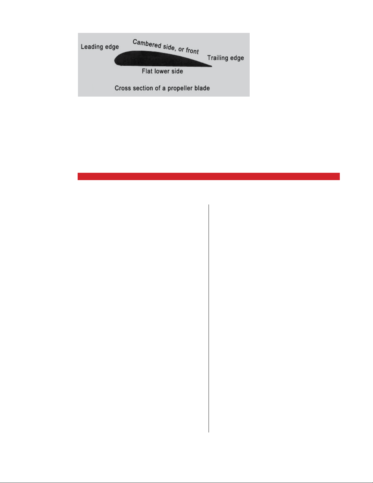
PROPELLERS
Look at the cross
section of a
propeller blade.
Essentially, the
same process
creates lift.
LEFT: Level Flight.
A wing creating
moderate lift. Air
vortices (lines) stay
close to the wing.
RIGHT: Climb.
Wing creating
signicant lift
force. Air vortices
still close to
the wing.
For the purposes of this manual, A2A just wants you
to be aware that both Bernoulli and Newton represent
complete explanations for how li is created.
The main thing we want to impress upon you here
is that when considering li and dealing with Bernoulli
and Newton, it is important and indeed critical to understand that BOTH explanations are COMPLETE EX-
PLANATIONS for how li is created. Bernoulli and Newton do NOT add to form a total li force. EACH theory
is simply a dierent way of COMPLETELY explaining the
same thing.
BOTH Bernoulli and Newton are in fact in play and
acting simultaneously on an airfoil each responsible
completely and independently for the li being created
on that airfoil.
Hopefully we have sparked your interest in the direction of proper research.
WHAT IS A STALL?
In order for a wing to produce eicient li, the air must
flow completely around the leading (front) edge of the
wing, following the contours of the wing. At too large an
angle of attack, the air cannot contour the wing. When
this happens, the wing is in a “stall.”
Typically, stalls in aircra occur when an airplane
loses too much airspeed to create a suicient amount of
li. A typical stall exercise would be to put your aircra
into a climb, cut the throttle, and try and maintain the
climb as long as possible. You will have to gradually pull
back harder on the stick to maintain your climb pitch
and as speed decreases, the angle of attack increases.
At some point, the angle of attack will become so great,
that the wing will stall (the nose will drop).
STA LL
The angle of attack has become too large. The boundary layer vortices have separated from the top surface
of the wing and the incoming flow no longer bends completely around the leading edge. The wing is stalled, not
only creating little li, but significant drag.
Can a propeller stall?
What do you think? More on this below.
Stall. A wing that
is stalled will be
unable to create
signicant lift.
56
A2ASIMULATIONS
:::
CHER OKEE 180 MAN UAL www.a2asimulations.com
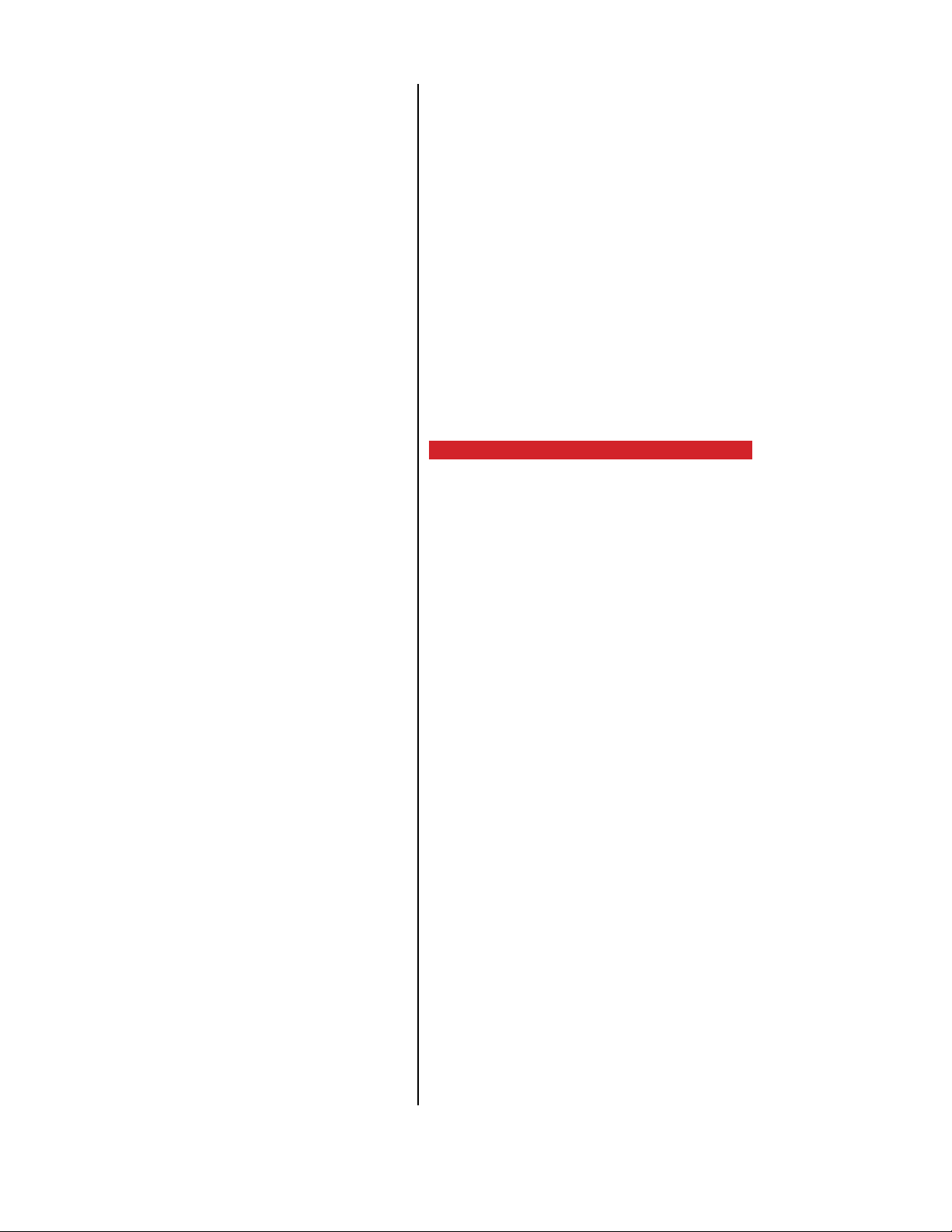
LIFT VS ANGLE OF ATTACK
Every airfoil has an optimum angle at which it attacks
the air (called angle of attack, or AoA), where li is at
it’s peak. The li typically starts when the wing is level,
and increases until the wing reaches its optimum angle,
lets say 15-25 degrees, then as it passes this point, the
li drops o. Some wings have a gentle drop, others can
actually be so harsh, as your angle of attack increases
past this critical point, the li drops o like a cli. Once
you are past this point of li and the angle is so high,
the air is just being plowed around in circles, creating
almost no li but plenty of drag. This is what you experience when you stall an aircra. The bueting or shaking
of the aircra at this stall position is actually the turbulent air, created by your stalling wing, passing over your
rear stabilizer, thus shaking the aircra. This shaking
can sometimes become so violent, you can pop rivets
and damage your airframe. You quickly learn to back
o your stick (or yoke) when you feel those shudders
approaching.
Notice in the diagram on the next page, how the airfoil creates more li as the angle of attack increases.
Ideally, your wing (or propeller) will spend most of it’s
time moving along the le hand side of this curve, and
avoid passing over the edge. A general aviation plane
that comes to mind is the Piper Cherokee. An older version has what we call a “Hershy bar wing” because it
is uniform from the root to the tip, just like an Hershy
chocolate bar. Later, Piper introduced the tapered wing,
which stalled more gradually, across the wing. The Hershy bar wing has an abrupt stall, whereas the tapered
wing has a gentle stall.
A propeller is basically a wing except that instead of
relying on incoming air for li, it is spinning around to
create li, it is perpendicular to the ground, creating a
backwards push of air, or thrust. Just remember, whether a propeller is a fixed pitch, variable pitch, or constant
speed, it is always attacking a variable, incoming air,
and lives within this li curve.
phases of flight, that we will just let you experience for
the first time yourself.
PROP OVERSPEED
A fixed pitch prop spends almost all of it’s life out
of it’s peak thrust angle. This is because, unless the
aircra is travelling at a specific speed and specific
power it was designed for, it’s either operating too
slow or too fast. Lets say you are flying a P-40 and
have the propeller in MANUAL mode, and you are
cruising at a high RPM. Now you pitch down, what is
going to happen? The faster air will push your prop
faster, and possibly beyond it’s 3,000 RPM recom
mended limit. If you pitch up your RPM will drop, losing engine power and propeller eiciency. You really
don’t have a whole lot of room here to play with, but
you can push it (as many WWII pilots had to).
-
FROM STALL TO FULL POWER
With brakes on and idling, the angle at which the prop
attacks the still air, especially closer to the propeller
hub, is almost always too great for the prop to be creating much li. The prop is mostly behaving like a brake
as it slams it’s side into the air. In reality, the prop is creating very little li while the plane is not moving. This
eect is known as prop stall, and is part of the Accu-Sim
prop physics suite.
Once done with your power check, prepare for takeo. Once you begin your takeo run, you may notice
the aircra starts to pull harder aer you start rolling
forward. This is the propeller starting to get its proper
“bite” into the air, as the propeller blades come out of
their stalled, turbulent state and enter their comfortable high li angles of attack it was designed for. There
are also other good physics going on during all of these
www.a2asimulations.com CHERO KEE 180 MAN UAL
:::
A2ASIMULATIONS
57

GENERAL
58
A2ASIMULATIONS
:::
CHER OKEE 180 MAN UAL www.a2asimulations.com

ENGINES
Number of Engines: 1
Engine Manufacturer: Lycoming
Engine Model Number: O-360-A3A
Rated Horsepower: 180
Rated Speed (rpm): 2700
Bore (inches): 5.125
Stroke (inches): 4.375
Displacement (cubic inches): 361
Compression Ratio: 8.5:1
Engine Type: 4 Cylinder, Horizontally Opposed, Direct Drive, Air Cooled
PROPELLERS
Number of Propellers: 1
Propeller Manufacturer : Sensenich
Model: M76EMMS
Number of Blades: 2
Propeller Diameter (inches): 76
Propeller Type: Fixed Pitch
FUEL
Fuel Capacity (U.S. gal.): 50
Usable Fuel, Total: 48
Fuel Grade: Aviation
Minimum Octane: 100/130
Specified Octane: 100LL
OIL
Oil Capacity (U.S. Quarts): 8
Oil Specification: 15W-50 OR 20W-50
Oil Viscosity per Average Ambient Temp. for Starting
MAXIMUM WEIGHTS
NORMAL UTILITY
Maximum Takeo Weight (lbs) 2400 1950
Maximum Landing Weight (lbs) 2400 1950
Maximum Weights in Baggage
Compartment
200 0
STANDARD AIRPLANE WEIGHTS
Standard Empty Weight (lbs): 1270 (Accu-Sim is 1,350)
Weight of a standard airplane including
unusable fuel, full operating fluids and full oil
Maximum Useful Load (lbs): 1130
The dierence between the Maximum Takeo Weight
and the Standard Empty Weight
BAGGAGE SPACE
Compartment Volume (cubic feet): 17
Entry Width (inches): 22
Entry Height (inches): 20
SPECIFIC LOADINGS
Wing Loading (lbs per sq ): 15.0
Power Loading (lbs per hp): 3.3
www.a2asimulations.com CHERO KEE 180 MAN UAL
:::
A2ASIMULATIONS
59

LIMITATIONS
60
A2ASIMULATIONS
:::
CHER OKEE 180 MAN UAL www.a2asimulations.com

HIS SECTION PROVIDES THE “FAA APPROVED”
operating limitations, instrument markings,
T
color coding and basic placards necessary for
the operation of the airplane and its systems.
This airplane must be operated as a normal of utility
category airplane in compliance with the operating limitations stated in the form of placards and markings and
those given in this section and this complete handbook.
AIRSPEED LIMITATIONS
Never Exceed Speed (VNE): 171 IAS (mph)
Do not exceed this speed in any operation.
Maximum Structural Cruising Speed (VNO): 140 IAS (mph)
Do not exceed this speed except in smooth
air and then only with caution
Design Maneuvering Speed (VA)
Do not make full or abrupt control movements above this speed
At 2400 LBS. G.W.: 129 IAS (mph)
Caution: Maneuvering speed decreases at lighter weight
as the eects of aerodynamic forces become more
pronounced. Linear interpolation may be used for
intermediate gross weights. Maneuvering speed should
not be exceeded while operating in rough air.
Maximum Flaps Extended Speed (VFE): 115 IAS (mph)
Do not exceed this speed with the flaps extended
AIRSPEED INDICATOR MARKINGS
Red Radial Line (Never Exceed): 170
Yellow Arc (Caution Range – Smooth Air Only): 140
Greed Arc (Normal Operating Range): 65 to 140
White Arc (Flap Down): 55 to 115
POWER PLANT LIMITATIONS
Number of Engines: 1
Engine Manufacturer : Lycoming
Engine Model No.: 0360-A3A
ENGINE OPERATING LIMITS
Maximum Horsepower: 180
Maximum Rotation Speed (RPM): 2700
Maximum Oil Temperature: 245°F
FUEL
Minimum Pressure (red line): .5 PSI
Maximum Pressure (red line): 8 PSI
Fuel Grade (AVGAS ONLY) (min octane): 100/130 - Green
PROPELLER
Number of Propellers: 1
Propeller Manufacturer : Sensenich
Propeller Model: 76EM8S5-60
Propeller Diameter: 76 inches
Propeller Tolerance
Static RPM at maximum: Not below 2275 RPM
Permissible throttle setting: Not above 2700 RPM
FLIGHT LOAD FACTORS
Positive Load Factor (max): 3.8G(Normal) 4.4G(Utility)
Negative Load Factor (max):
No inverted maneuvers approved
TYPES OF OPERATION
The airplane is approved for the following operations
when equipped in accordance with FAR 91 or FAR 135.
Day V.F.R. Night V.F.R.
Day I.F.R. Night I.F.R.
Non Icing
FUEL LIMITATIONS
Total Capacity: 50 U.S. GAL
Unusable Fuel: 2 U.S. GAL
Usable Fuel: 48 U.S. GAL
The unusable fuel for this airplane has been determined
as 1.0 gallon in each wing in critical flight attitudes.
The usable fuel in this airplane has been
determined as 24.0 gallons in each wing.
OIL PRESSURE
Minimum (red line): 25 PSI
Maximum (red line): 90 PSI
www.a2asimulations.com CHERO KEE 180 MAN UAL
:::
A2ASIMULATIONS
61

NORMAL PROCEDURES
62
A2ASIMULATIONS
:::
CHER OKEE 180 MAN UAL www.a2asimulations.com

HIS SECTION CLEARLY DESCRIBES
the recommended procedures for
T
the conduct of normal operations
for the Cherokee 180. All of the required
(FAA regulations) procedures and those
necessary for the safe operation of the
airplane as determined by the operating and design features of the airplane
are presented.
These procedures are provided to present a source of reference and
review and to supply information on procedures which are not the same
for all aircra. Pilots should familiarize themselves with the procedures
given in this section in order to become proficient in the normal operations of the airplane. The first portion of this section consists of a short
form check list which supplies an action sequence for normal operations
with little emphasis on the operation of the systems.
The remainder of the section is devoted to amplified normal procedures which provide detailed information and explanations of the procedures and how to perform them. This portion of the section is not intended for use as an in-flight reference due to the lengthy explanations.
The short form check list should be used for this purpose.
www.a2asimulations.com CHERO KEE 180 MAN UAL
:::
A2ASIMULATIONS
63

NORMAL PROCEDURES
AIRSPEEDS FOR NORMAL OPERATION
The following airspeeds are those which are significant
to the safe operation of the airplane. These figures are
for standard airplanes flown at gross weight under standard conditions at sea level. Performance for a specific
airplane may vary from published figures depending
upon the equipment installed, the condition of the engine, airplane and equipment, atmospheric conditions
and piloting technique.
Vx Best Angle of Climb Speed 76 mph
Vy Best Rate of Climb Speed 85 mph
Vbg Best Glide Speed 83 mph
Vs Stall Speed, normal configuration 64 mph
Vso Stall Speed, landing configuration 55 mph
Vfo Maximum Flap Extension Speed 115 mph
Va Maneuvering Speed (at gross weight) 129 mph
Vno Maximum Structural Cruising Speed 140 mph
Vne Never Exceed Speed 171 mph
Normal Climb Out 100 mph
Short Field T/O, Flaps 25° 74 mph
Normal Landing Approach, Flaps Up 85 mph
Normal Landing Approach, Flaps 40° 76 mph
Short Field Approach, Flaps 40° 76 mph
Maximum Demonstrated
Crosswind Velocity
PREFLIGHT
When the aircra is stopped with the engine o, press
SHIFT-8 to bring up the interactive preflight inspection.
17 kts
STARTING
Aer completion of preflight inspection:
1. Master switch ON
2. Check fuel quantity indicators
3. Apply and hold toe brakes or use parking brake.
4. Set the carburetor heat control
in the full “COLD”position.
5. Select the desired tank with the fuel valve.
6. Move the mixture to the full “RICH” position.
7. Open the throttle 1/8 to 1/4 inch.
8. Turn the electric fuel pump “ON”.
In cold weather (below 40 degrees F.) prime the engine with one to three full strokes of the priming pump. If
extremely cold, starting will be aided by pulling the propeller through by hand four to five revolutions (can use
the engine starter as well) with the mag switch “OFF”.
Aer priming, turn the electric master switch on. Engage the starter and allow the engine to turn approximately one full revolution, then turn the ignition switch
to the “Both” magneto position.
When the engine is firing evenly, adjust the throttle
to 800 RPM. Check the oil pressure gauge for a pressure
indication. If oil pressure is not indicated within thirty
seconds, stop the engine and determine the trouble. If
the engine fails to start at the first attempt, another attempt should be made without priming. If this fails, it is
possible that the engine is over primed. Turn the magneto switch o, open the throttle slowly, and rotate the
engine approximately ten revolutions with the starter.
Re-prime the engine with one half the amount used in
the initial attempt, turn the magneto switch to “Both”,
and repeat the starting procedure.
64
A2ASIMULATIONS
WARM-UP
As soon as the engine starts, the oil pressure should be
checked. If no pressure is indicated within thirty seconds, stop the engine and determine the trouble. In
cold weather it will take a few seconds longer to get an
oil pressure indication.
Warm-up the engine at 800 to 1200 RPM for at least
two minutes.
:::
CHER OKEE 180 MAN UAL www.a2asimulations.com

GROUND CHECK
With the engine running at 2000 RPM, switch from both
magnetos to only one and note the RPM loss; switch to
the other magneto and again note the RPM loss. Drop
o on either magneto should not exceed 125 RPM.
Check vacuum gauge. Indicator should read 5” Hg +/-
l” Hg at 2000 RPM.
Check both the oil temperature and pressure. The
temperature may be low for some time if the engine is
being run for the first time of the day, but as long as the
pressure is within limits the engine is ready for take-o.
Carburetor heat should also be checked prior to takeo to be sure that the control is operating properly and
to clear any ice which may have formed during taxiing.
Avoid prolonged ground operation with carburetor heat
ON as the air is unfiltered.
Take-o may be made as soon as ground check is
completed, providing that the throttle may be opened
fully without back firing or skipping, and without reduction in engine oil pressure.
TAKE-OFF
Just before take-o the following items should be
checked:
STA LLS
The gross weight stalling speed of the Cherokee with
power o and full flaps is 57 MPH. This speed is increased 9 miles per hour with the flaps up. Stall speeds
at lower weights will be correspondingly less.
1. Controls free
2. Flaps “UP”
3. Tab set
4. Mixture “RICH” (leaned for smooth op-
eration at high elevations)
5. Carburetor heat “OFF”
6. Fuel on proper tank
7. Electric fuel pump “ON”
8. Engine gauges normal
9. Door latched
10. Altimeter and heading set
11. Safety belts/shoulder harness - fastened
The takeo technique is conventional for the Cherokee. The tab should be set slightly a of neutral, with the
exact setting determined by the loading of the aircra. Al
low the airplane to accelerate to 50 to 60 miles per hour,
then ease back on the wheel enough to let the airplane fly
itself o the ground. Premature raising of the nose, or rais
ing it to an excessive angle will result in a delayed take-o.
Aer takeo let the aircra accelerate to the desired climb
speed by lowering the nose slightly. To shorten take-o
distance, flaps extended up to 25° may be used.
CLIMB
The best rate of climb at gross weight will be obtained
at 85 miles per hour. The best angle of climb may be obtained at 74 miles per hour. At lighter than gross weight
these speeds are reduced somewhat. For climbing
enroute a speed of 100 miles per hour is recommended.
This will produce better forward speed and increased
visibility over the nose during the climb.
CRUISING
The cruising speed of the Cherokee is determined by
many factors including power setting, altitude, temperature, loading, and equipment installed on the airplane. The normal cruising power is 55-75% of the rated
horsepower of the engine. True airspeeds which maybe
obtained at various altitudes and power settings can be
determined from the charts in this handbook.
Use of the mixture control in cruising flight reduces
fuel consumption significantly, especially at higher altitudes, and reduces lead deposits when the alternate
fuels are used. The mixture should be leaned when 75%
power or less is being used. If any doubt exists as to the
amount of power being used, the mixture should be in
the FULL RICH position for all operations. Always enrich
-
the mixture before increasing power settings.
The normal maximum cruising power is 75% of the
rated horsepower of the engine. Airspeeds which may
-
be obtained at various altitudes and power settings can
be determined from the performance graphs provided.
Use of the mixture control in cruising flight reduces
fuel consumption significantly, especially at higher altitudes. The mixture should be leaned during cruising
operation above 5000 . altitude and at pilot’s discretion at lower altitudes when 75% power or less is being
used. If any doubt exists as to the amount of power being used, the mixture should be in the full “RICH” position for all operations under 5000 feet
To lean the mixture, disengage the lock and pull the
mixture control until the engine becomes rough, indicating that the lean mixture limit has been reached in
the leaner cylinders. Then enrich the mixture by pushing
www.a2asimulations.com CHERO KEE 180 MAN UAL
:::
A2ASIMULATIONS
65

NORMAL PROCEDURES
the control towards the instrument panel until engine
operation becomes smooth. If the airplane is equipped
with the optional exhaust gas temperature (EGT) gauge,
operate anywhere between peak EGT to 50° ROP (rich
of peak).
The continuous use of carburetor heat during cruising flight decreases engine eiciency. Unless icing
conditions in the carburetor are severe, do not cruise
with the heat on. Apply full carburetor heat slowly and
only for a few seconds at intervals determined by icing
severity.
In order to keep the airplane in best lateral trim during cruising flight the fuel should be used alternately
from each tank. It is recommended that one tank should
be used for one hour aer takeo, then the other tank
used for two hours, then return to the first tank, which
will have approximately one and one half hour of fuel
remaining if the tanks were full plus reserve at takeo.
The second tank will contain approximately one half
hour of fuel.
APPROACH AND LANDING
Landing check list:
1. Fuel on proper tank
2. Mixture – rich
3. Elec. fuel pump on
4. Flaps - set
5. Fasten belts/harness
The airplane should be trimmed to an approach
speed of about 85 miles per hour, with flaps up. The
flaps can be lowered at speeds up to ll5 miles per hour,
it desired, and the approach speed reduced 3 MPH for
each additional notch of flaps. Carburetor heat should
not be applied unless there is an indication of carburetor icing, since the use of carburetor heat causes a reduction in power which may be critical in case of a go
around. Full throttle operation with heat on is likely to
cause detonation.
The amount of flap used during landings and the
speed of the aircra at contact with the runway should
be varied according to the landing surface, and existing
conditions both wind wise and load wise. It is generally
good practice to contact the ground at the minimum
possible safe speed consistent with existing conditions.
Normally the best technique for short and slow landings is to use full flap and enough power to maintain
the desired airspeed and approach flight path. Mixture
should be full rich, fuel on the fullest tank, carburetor
heat o, and electric fuel pump on. Reduce the speed
during the flare-out and contact the ground close to the
stalling speed (50 to 60 MPH). Aer ground contact hold
the nose wheel o, as long as possible. As the airplane
slows down, drop the nose and apply the brakes. If hard
braking is required, there will be less chance of skidding
66
A2ASIMULATIONS
:::
CHER OKEE 180 MAN UAL www.a2asimulations.com

the tires if the flaps are retracted before applying the
brakes, otherwise leave the flaps down for aerodynamic
braking. Braking is most eective when back pressure is
applied to the control wheel, putting most of the aircra
weight on the main wheels. In high wind conditions,
particularly in strong cross winds, it may be desirable
to approach the ground at higher than normal speeds,
with partial or no flaps.
To stop the engine, aer landing and when clear of
the runway, pull the mixture control full out to idle cuto. When using alternate fuels, the engine should be
run up to 1200 R.P.M. for one minute prior to shutdown
to clean out any unburned fuel. Aer the engine stops,
turn the ignition and master switches o, and retract
the flaps.
GROUND HANDLING AND MOORING
The Cherokee should be moved on the ground with the
aid of the nose wheel tow bar provided with each plane
and secured in the baggage compartment. Tie downs
may be secured to rings provided under each wing,
and to the tall skid. The aileron and stabilator controls
should be secured by looping the safety belt through
the control wheel, and pulling it tight. The rudder is
held in position by its connections to the nose wheel
steering, and normally does not have to be secured. The
flaps are locked when in the full up position, and should
be le retracted.
WEIGHT AND BALANCE -
It is the responsibility of the owner and pilot to determine
that the airplane remains within the allowable weight vs
center of gravity envelope while in flight. For weight and
balance data see the Airplane Flight Manual and Weight
and Balance Form supplied with each airplane.
www.a2asimulations.com CHERO KEE 180 MAN UAL
:::
A2ASIMULATIONS
67

PERFORMANCE
HE PERFORMANCE INFORMATION PRESENTED
in this section is based on measured Flight
T
The performance charts are unfactored and do not
The performance however can be duplicated by fol-
Test Data corrected to ICAO standard day conditions and analytically expanded for the various
parameters of weights, altitude, temperature, etc.
make any allowance for varying degree of pilot proficiency or mechanical deterioration of the aircra.
lowing the stated procedures in a properly maintained airplane.
Eects of conditions not considered on the charts must be evaluated by the
pilot, such as the eect of so or grass runway surface on takeo and landing
performance, or the eect of winds alo on cruise and range performance. Endurance can be greatly aected by improper leaning procedures, and in-flight
fuel flow and quantity checks are recommended.
68
A2ASIMULATIONS
:::
CHER OKEE 180 MAN UAL www.a2asimulations.com
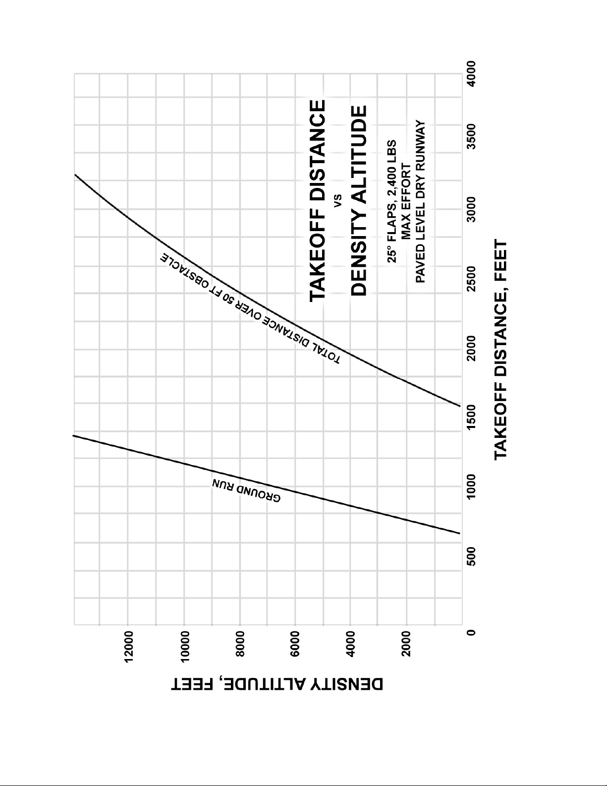
www.a2asimulations.com CHERO KEE 180 MAN UAL
:::
A2ASIMULATIONS
69

PERFORMANCE
70
A2ASIMULATIONS
:::
CHER OKEE 180 MAN UAL www.a2asimulations.com

www.a2asimulations.com CHERO KEE 180 MAN UAL
:::
A2ASIMULATIONS
71
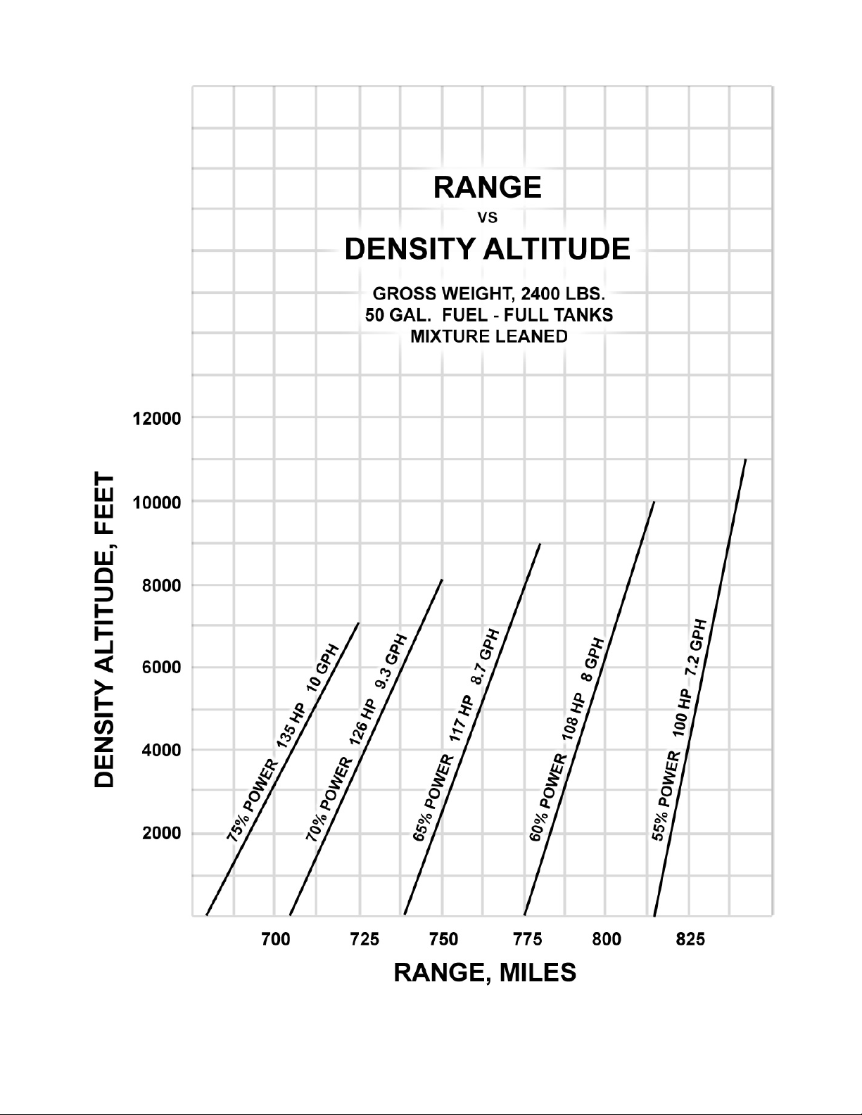
PERFORMANCE
72
A2ASIMULATIONS
:::
CHER OKEE 180 MAN UAL www.a2asimulations.com
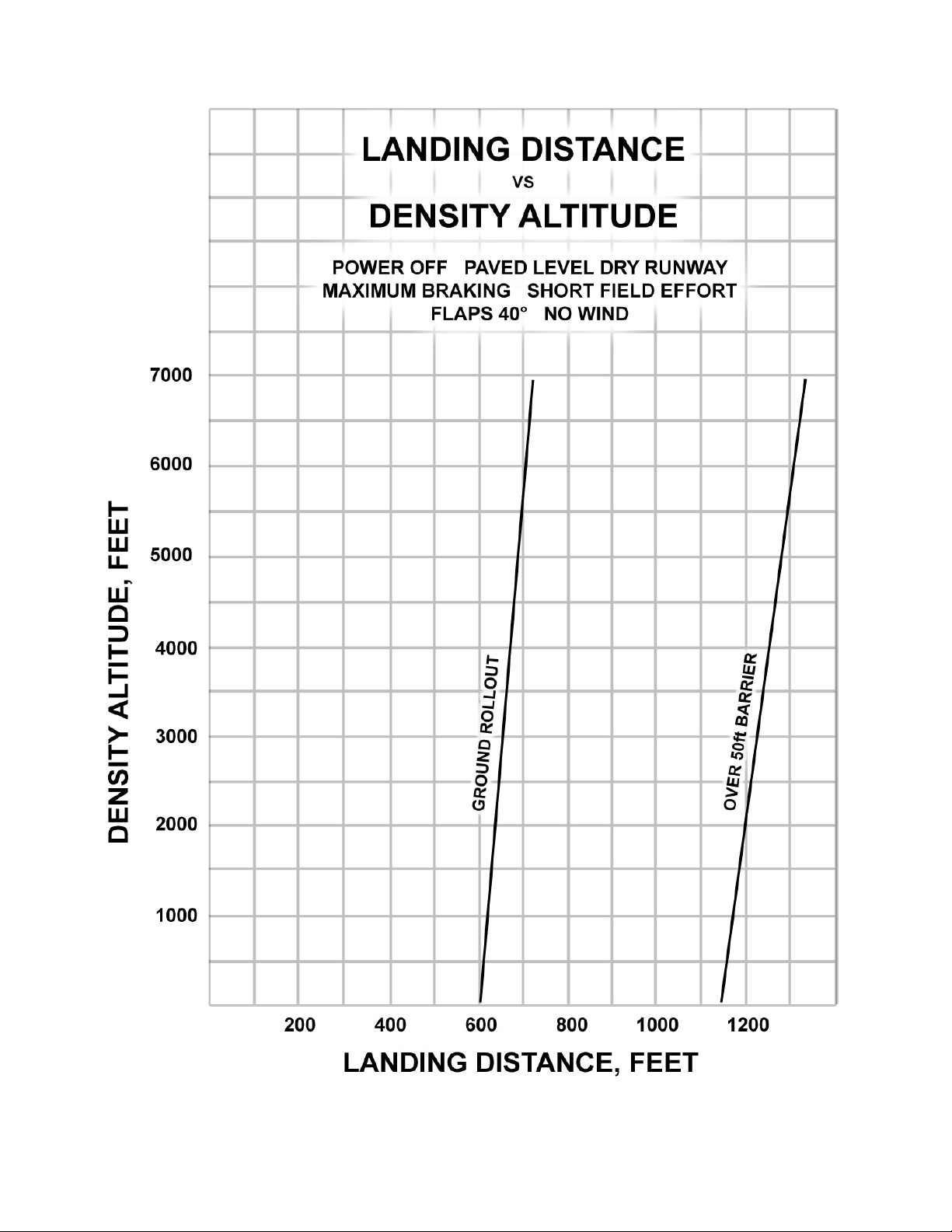
www.a2asimulations.com CHERO KEE 180 MAN UAL
:::
A2ASIMULATIONS
73

PERFORMANCE
74
A2ASIMULATIONS
:::
CHER OKEE 180 MAN UAL www.a2asimulations.com

www.a2asimulations.com CHERO KEE 180 MAN UAL
:::
A2ASIMULATIONS
75

WEIGHT AND BALANCE
76
A2ASIMULATIONS
:::
CHER OKEE 180 MAN UAL www.a2asimulations.com

N ORDER TO ACHIEVE THE PERFORMANCE AND FLYING CHARACTERIS-
tics which are designed into the airplane, it must be flown with the
I
weight and center of gravity (C.G.) positioned within the approved operating range (envelope). Although the airplane oers flexibility of loading, it cannot be flown with the maximum number of adult passengers, full
fuel tanks, and maximum baggage. With the flexibility comes responsibility. The pilot must ensure that the airplane is loaded within the loading
envelope before he makes a takeo.
Misloading carries consequences for any aircra. An
overloaded airplane will not take o, climb, or cruise as
well as a properly loaded one. The heavier the airplane
is loaded, the less climb performance it will have.
Center of gravity is a determining factor in flight characteristics. If the C.G. is too far forward in any airplane,
it may be diicult to rotate for takeo or landing. If the
C.G. is too far a, the airplane may rotate prematurely on
takeo or tend to pitch up during climb. Longitudinal stability will be reduced. This can lead to inadvertent stalls
and even spins, and spin recovery becomes more diicult
as the center of gravity moves a of the approved limit.
WEIGHT AND BALANCE LOADING FORM
(example using two 170 lbs passengers, full fuel, and 50lbs of baggage)
Weight
(lbs.) Arm A
Basic Empty
Weight
Front Seats 340 85.5 29,070
Rear Seats* 0 118.1 0
Baggage* 50 142.8 7,140
Fuel (max 48gal) 288 95.0 27,360
Total 2,033 180,208
NOTE: Empty weight includes two gallons of
unusable fuel, so the max fuel capacity for weight
and balance calculations is 50 – 2 = 48 gallons
1,355 86.08 116,638
Datum
(in.)
Moment
(in-lbs.)
How to calculate the center of gravity:
Total Moment ÷ Total Weight = C.G. (center of gravity)
180,208 ÷ 2,033 = 88.64
C.G. = 88.64
Normal Category Limits: 84.0 - 95.8
Utility Category Limits: 84.0 – 86.5*
*Utility Category Operation – No baggage or rear
passengers allowed. Max 1,950 lbs.
www.a2asimulations.com CHERO KEE 180 MAN UAL
:::
A2ASIMULATIONS
77

AIRPLANE & SYSTEM DESCRIPTIONS
78
A2ASIMULATIONS
:::
CHER OKEE 180 MAN UAL www.a2asimulations.com

HE PA-28-180 CHEROKEE IS A
single-engine, low-wing mono
T
plane of all metal construction.
It has fourplace seating, two hundred
pound baggage capacity, and a 180
horsepower engine.
ENGINE AND PROPELLER
The Cherokee is powered by a Lycoming O-360-A3A, 180 H.P. engine with a starter, 35
ampere 12 volt alternator, voltage regulator, shielded ignition, vacuum pump drive,
fuel pump and a dry, automotive type carburetor air filter.
The exhaust system is of the cross-over type to reduce back pressure and improve performance. It is made entirely from stainless steel and is equipped with dual
mulers. A heater shroud around the mulers is provided to supply heat for both the
cabin and carburetor de-icing.
The Sensenich fixed-pitch 76EM8S5-60 propeller is made from a one-piece
alloy forging.
-
STRUCTURES
All structures are of aluminum alloy construction and are designed to ultimate load
factors well-in excess of normal requirements. All exterior surfaces are primed with
etching primer and painted with acrylic enamel.
The wings are attached to each side of the fuselage by inserting the butt ends
of the respective main spars into a spar box carry through which is an integral part
of the fuselage structure, providing in eect a continuous main spar with splices at
each side of the fuselage. There are also fore and a attachments at the rear spar
and at an auxiliary front spar.
The wing airfoil section is a laminar flow type, NACA 652-415 with the maximum thickness about 40% a of the leading edge. This permits the main spar carry
through structure to be located under the rear seat providing unobstructed cabin
floor space ahead of the rear seat.
www.a2asimulations.com CHERO KEE 180 MAN UAL
:::
A2ASIMULATIONS
79

AIRPLANE & SYSTEM DESCRIPTIONS
LANDING GEAR
The three landing gears use a Cleveland 600 x 6 wheel,
the main wheels being provided with Cleveland single
disc hydraulic brake assemblies, No. 30-55. All wheels
use 600 x 6 four ply tires with tubes.
The nose gear is steerable through a 30 degree arc
by use of the rudder pedals. A spring device is incorporated in the rudder pedal torque tube assembly to aid in
rudder centering and to provide rudder trim. The nose
gear steering mechanism also incorporates a hydraulic shimmy dampener. The oleo struts are of the air-oil
type, with normal extension being 3.25 inches for the
nose gear and 1.50 inches for the main gear under normal static load (empty weight of airplane plus full fuel
and oil).
The standard brake system for the Cherokee consists of a hand lever and master cylinder which is located below and behind the le center of the instrument
sub-panel. The brake fluid reservoir is installed on the
top le front face of the firewall. The parking brake is
incorporated in the master cylinder and is actuated by
pulling back on the brake lever, depressing the knob attached to the handle and releasing the brake lever. To
release the parking brake, pull back on the lever to disengage the catch mechanism and allow the handle to
swing forward.
Optional toe brakes are available to supplement the
standard hand lever and parking brake system.
CONTROL SYSTEMS
Dual controls are provided as standard equipment, with
a cable system used between the controls and the surfaces. The horizontal tail is of the all movable slab type,
with an anti-servo tab which also acts as a longitudinal
trim tab, actuated by a control on the cabin ceiling. The
stabilator provides extra stability and irreconcilability
with less size, drag, and weight than conventional tail
surfaces. The ailerons are provided with a dierential
action which tends to eliminate adverse yaw in turning
maneuvers, and also reduces the amount of coordination required in normal turns. The flaps are manually
80
A2ASIMULATIONS
:::
CHER OKEE 180 MAN UAL www.a2asimulations.com

operated, balanced for light operating forces and spring
loaded to return to the up position. A past-center lock
incorporated in the actuating linkage holds the flap
when it is in the up position so that it may be used as
a step on the right side. The flap will not support a step
load except when in the full up position, so it must be
completely retracted when used as a step. [Editor’s
note: Even though its designed to be stepped on, many
Cherokee owners prefer passengers avoid stepping on
the flap]. The flaps have three extended positions, 10,
25 and 40 degrees.
FUEL SYSTEM
Fuel is stored in two twenty-five gallon tanks which are
secured to the leading edge structure of each wing by
screws and nut plates. This allows easy removal for service or inspection. The standard quantity of fuel is 50
gallons. To obtain 36 gallons of fuel, fill the tanks only
to the bottom of the filler neck indicator (tabs), which
extends some distance into the tanks.
This system allows the fuel quantity to be varied conveniently according to the payload. An auxiliary electric
fuel pump is provided for use in case of failure of the
engine driven pump. The electric pump should be on
for all take-os and landings. The fuel strainer, which
is equipped with a quick drain, is located on the front
lower le corner of the firewall. This strainer should be
drained regularly to check for water or sediment accumulation. To drain the lines from the tanks, the tank selector valve must be switched to each tank in turn, with
the electric pump on, and the gascolator drain valve
opened. Each tank has an individual quick drain located
at the bottom, inboard, rear corner. Fuel quantity and
pressure are indicated on gauges located in the engine
gauge cluster on the right side of the instrument panel.
ELECTRICAL SYSTEM
The electrical system includes a 12 volt alternator, battery, voltage regulator and master switch relay. The
battery, regulator and relay are mounted in the battery
compartment immediately a of the baggage compartment. Access for service or inspection is conveniently
obtained through a removable panel at lower right corner of the compartment.
Electrical switches and fuses are located on the lower
le center of the instrument panel, and the le side of the
instrument sub-panel. Standard electrical accessories include: Starter, Electric Fuel pump, Fuel Gauge, Stall Warning Indicator, Cigarette Lighter and Ammeter. Navigation
Lights, Anti-Collision Light, Landing Light, Instrument
Lighting and the Cabin Dome Light are oered as optional accessories. Circuit provisions are made to handle
optional communications and navigational equipment.
Installed on the Cherokees is the F.T.P. (full time power) electrical system. Derived from the system are many
advantages both in operation and maintenance. The
main advantage is, of course, full electrical power output
regardless of engine R.P.M. This is a great improvement
for radio and electrical equipment operation. Also because of the availability of generator output at all times,
the battery will be charging for a greater percentage of
use, which will greatly improve cold-morning starting.
Unlike previous generator systems, the ammeter
does not indicate battery discharge; rather it displays
www.a2asimulations.com CHERO KEE 180 MAN UAL
:::
A2ASIMULATIONS
81

AIRPLANE & SYSTEM DESCRIPTIONS
in amperes the load placed on the alternator. With all
electrical equipment o (except the master switch) the
ammeter will be indicating the amount of charging current demanded by the battery. As each item of electrical equipment is turned on, the current will increase to
a total appearing on the ammeter. This total includes
the battery. The maximum continuous load for night
flight, with radios on, is about 30 amperes. This 30 ampere value, plus approximately two amperes for a fully
charged battery, will appear continuously under these
flight conditions. The amount of current shown on the
ammeter will tell immediately whether the alternator
system is operating normally, as the amount of current
shown should equal the total amount of amperes being
drawn by the equipment which is operating. If no output is indicated on the ammeter during flight, reduce
the electrical load by turning o all unnecessary electrical equipment. Check both 5 ampere field breaker and
60 ampere output breaker and reset if open. lf neither
circuit breaker is open, turn o the master switch for 30
seconds to reset the overvoltage relay. If ammeter continues to indicate no output, maintain minimum electrical load and terminate flight as soon as practical.
HEATING AND VENTILATING SYSTEM
Heat for the cabin interior and the defroster system
is provided by a heater mu attached to the exhaust
system. The amount of heat desired can be regulated
with the controls located on the lower right side of the
instrument panel. Fresh air inlets are located in the
leading edge of the wing at the intersection of the tapered and straight sections. A large adjustable outlet is
located on the side of the cabin near the floor at each
seat location.
CABIN FEATURES
The instrument panel of the Cherokee is designed to accommodate the customary advanced flight instruments
and all the normally required power plant instruments.
The Artificial Horizon, Directional Gyro and some Turn
and Bank instruments are vacuum operated through
use of a vacuum pump installed on the engine. Later C
Model Cherokees are equipped with electric turn and
bank instruments. A natural separation of the flight
group and the power group is provided by placing the
communications and radio navigational equipment in
the center of the panel.
82
A2ASIMULATIONS
:::
CHER OKEE 180 MAN UAL www.a2asimulations.com

CENTER STACK AVIONICS SUITE
We have spent much time developing extra modes and
functions that you won’t find in any P3D airplane, like
independent DME receiver, pilot- programmable COMM
channels and NAV OBS mode. For example, you should
pay attention to the autopilot. Even though it may look
familiar, you need to learn how to operate it properly
or you may find you plane going in completely wrong
direction.
The avionics suite in your Accu-Sim Piper Cherokee
180 is so complete, the best source for your information
is straight from the manufacturer. Below are links to the
latest manuals online:
DVOR
http://www.davtron.com/cmsAdmin/uploads/m903_
brochure.pdf
Clock
http://www.adstcoil.com/admin/userfiles/file/manuals/lc-2/ads_lc2_oper_instruction.pdf
Autopilot:
http://sharepoint.s-tec.com/Documentation/
Shared%20Documents/Pilot%20Operating%20Handbooks%20(POH)/System%20Twenty_Thirty_%20Thirty%20ALT.pdf
ADF, DME:
https://dealer.bendixking.com/servlet/com.honeywell.
aes.utility.PDFDownLoadServlet?FileName=/TechPubs/
repository/006-18110-0000_5.pdf
www.a2asimulations.com CHERO KEE 180 MAN UAL
:::
A2ASIMULATIONS
83

AIRPLANE & SYSTEM DESCRIPTIONS
84
A2ASIMULATIONS
:::
CHER OKEE 180 MAN UAL www.a2asimulations.com

www.a2asimulations.com CHERO KEE 180 MAN UAL
:::
A2ASIMULATIONS
85

EMERGENCY PROCEDURES
86
A2ASIMULATIONS
:::
CHER OKEE 180 MAN UAL www.a2asimulations.com

HIS SECTION CONTAINS PROCEDURES THAT ARE
recommended if an emergency condition should
T
occur during ground operation, takeo, or in flight.
These procedures are suggested as the best course of ac-
tion for coping with the particular condition described,
but are not a substitute for sound judgment and common sense. Since emergencies rarely happen in modern
aircra, their occurrence is usually unexpected, and the
best corrective action may not always be obvious. Pilots should familiarize themselves with the procedures
given in this section and be prepared to take appropriate action should an emergency arise.
Most basic emergency procedures, such as power o landings, are a normal part of
pilot training. Although these emergencies are discussed here, this information is not
intended to replace such training, but only to provide a source of reference and review,
and to provide information on procedures that are not the same for all aircra. It is
suggested that the pilot review standard emergency procedures periodically to remain
proficient in them.
ENGINE POWER LOSS DURING TAKEOFF
1. If suicient runaway remains for a normal landing, land straight ahead.
2. If insuicient runaway remains:
a. Maintain safe airspeed
b. Make shallow turns to avoid obstructions
c. Flaps as situation requires
3. If suicient altitude to attempt a restart:
a. Maintain safe airspeed
b. Fuel selector — tank containing fuel
c. Electric fuel pump — check ON
d. Mixture — check RICH
e. Carburetor heat — ON
f. Primer — locked
4. If still no power, plan power o landing
www.a2asimulations.com CHERO KEE 180 MAN UAL
:::
A2ASIMULATIONS
87

EMERGENCY PROCEDURES
ENGINE POWER
LOSS IN FLIGHT
1. Fuel selector — tank containing fuel
2. Electric fuel pump — ON
3. Mixture — check RICH
4. Carburetor heat — ON
5. Engine gauges — check for indication
of cause of pwr loss
6. Primer — check locked
7. If no fuel pressure is indicated,
check tank selector position is
on a tank containing fuel.
8. When power is restored:
a. Carburetor heat — OFF
b. Electric fuel pump — OFF
9. If power is not restored, prepare
power o landing.
10. Trim for 76 KIAS
POWER OFF LANDING
1. Locate suitable field.
2. Establish spiral pattern
3. 1000 . above field at downwind
position for normal landing approach.
4. When field can easily be reached, slow
to 66 KIAS for shortest landing.
5. Touchdowns should normally be made at
lowest possible airspeed with full flaps.
6. When committed to landing:
a. Ignition — OFF
b. Master switch — OFF
c. Fuel selector — OFF
d. Mixture — idle cut-o
e. Seat belt and harness — tight
FIRE IN FLIGHT
1. Source of fire — check
2. Electrical fire (smoke in cabin):
a. Master switch — OFF
b. Vents — open
c. Cabin heat — OFF
d. Land as soon as practicable.
3. Engine fire:
a. Fuel selector — OFF
b. Throttle — Closed
c. Mixture — idle cut-o
d. Electric fuel pump — check OFF
e. Heater and defroster — OFF
f. Proceed with power o
landing procedure.
HIGH OIL TEMPERATURE
Land at nearest airport and
investigate the problem.
Prepare for a power o landing.
LOSS OF OIL PRESSURE
Land as soon as possible
and investigate cause.
Prepare for power o landing.
LOSS OF FUEL PRESSURE
1. Electric fuel pump — ON
2. Fuel selector — check on full tank
3. Land as soon as possible as. Low fuel
pressure may indicate a fuel leak.
88
A2ASIMULATIONS
:::
CHER OKEE 180 MAN UAL www.a2asimulations.com

ALTERNATOR FAILURE
CARBURETOR ICING
1. Verify failure
2. Reduce electrical load as much as possible.
3. Alternator circuit breakers — check
4. Alt switch — OFF 1 second then on
5. If no output:
a. Alt switch — OFF
b. Reduce electrical load and
land as practical.
SPIN RECOVERY
1. Throttle — idle
2. Ailerons — neutral
3. Rudder — full opposite to
direction of rotation
4. Control wheel — full forward
5. Rudder — neutral when rotation stops
6. Control wheel — smoothly
regain level flight altitude
1. Carburetor Heat — ON
2. Mixture — max. smoothness
ENGINE ROUGHNESS
1. Carburetor heat — ON
2. If roughness continues aer one min:
3. Carburetor heat — OFF
4. Mixture — max smoothness
5. Electric fuel pump — ON
6. Fuel selector — switch tanks
7. Engine gauges — check
8. Magneto switch — ”L”&“R” then BOTH
9. If operation is satisfactory on either one,
continue on that magneto at reduced
power and full “RICH” mixture to first
airport. Prepare for power o landing
www.a2asimulations.com CHERO KEE 180 MAN UAL
:::
A2ASIMULATIONS
89

EMERGENCY PROCEDURES EXPLAINED
90
A2ASIMULATIONS
:::
CHER OKEE 180 MAN UAL www.a2asimulations.com

HE FOLLOWING PARAGRAPHS ARE PRESENTED
to supply additional information for the purpose
T
of providing the pilot with a more complete un
derstanding of the recommended course of action and
probable cause of an emergency situation.
ENGINE POWER LOSS DURING TAKEOFF
The proper action to be taken if loss of power occurs
during takeo will depend on the circumstances of the
particular situation.
If suicient runway remains to complete a normal
landing, land straight ahead.
If insuicient runway remains, maintain a safe air-
speed and make only a shallow turn if necessary to
avoid obstructions. Use of flaps depends on the circumstances. Normally, flaps should be fully extended
for touchdown.
If suicient altitude has been gained to attempt a
restart, maintain a safe airspeed and switch the fuel
selector to another tank containing fuel. Check the
electric fuel pump to ensure that it is “ON” and that
the mixture is “RICH.” The carburetor heat should
be “ON” and the primer checked to ensure that it is
locked.
If engine failure was caused by fuel exhaustion, power will not be regained aer switching fuel tanks until
the empty fuel lines are filled. This may require up to
ten seconds.
If power is not regained, proceed with the Power O
Landing procedure.
indication of the cause of power loss. Check the engine
gauges for an indication of the cause of the power loss.
Check to ensure the primer is locked. If no fuel pressure
is indicated, check the tank selector position to be sure
it is on a tank containing fuel.
When power is restored move the carburetor heat
to the “OFF” position and turn “OFF” the electric fuel
pump. If the preceding steps do not restore power, prepare for an emergency landing.
If time permits, turn the ignition switch to “L” then to
“R” then back to “BOTH.” Move the throttle and
mixture control levers to dierent settings. This may
restore power if the problem is too rich or too lean a
mixture or if there is a partial fuel system restriction. Try
other fuel tanks. Water in the fuel could take some time
to be used up, and allowing the engine to windmill may
restore power. If power is due to water, fuel pressure indications will be normal.
If engine failure was caused by fuel exhaustion power will not be restored aer switching fuel tanks until
the empty fuel lines are filled. This may require up to
ten seconds. If power is not regained, proceed with the
Power O Landing procedure (refer to the emergency
check list and paragraph 3.13).
-
ENGINE POWER LOSS IN FLIGHT
Complete engine power loss is usually caused by fuel
flow interruption and power will be restored shortly
aer fuel flow is restored. If power loss occurs at a
low altitude, the first step is to prepare for an emergency landing. An airspeed of at least 76 KIAS should
be maintained.
If altitude permits, switch the fuel selector to another tank containing fuel and turn the electric fuel pump
“ON.” Move the mixture control to “RICH” and the carburetor heat to “ON.” Check the engine gauges for an
www.a2asimulations.com CHERO KEE 180 MAN UAL
POWER OFF LANDING
If loss of power occurs at altitude, trim the aircra for
best gliding angle 76 KIAS (if equipped, Air Cond. O)
and look for a suitable field. If measures taken to restore
power are not eective, and if time permits, check your
charts for airports in the immediate vicinity: it may be
possible to land at one if you have suicient altitude.
Real word tip: If possible, notify the FAA by radio of
your diiculty and intentions. If another pilot or passenger is aboard, let him help.
When you have located a suitable field, establish a
:::
A2ASIMULATIONS
91

EMERGENCY PROCEDURES EXPLAINED
spiral pattern around this field. Try to be at 1,000 feet
above the field at the downwind position, to make a
normal landing approach. When the field can easily be
reached, slow to 66 KIAS with flaps down for the shortest landing. Excess altitude may be lost by widening
your pattern, using flaps or slipping, or a combination
of these.
Touchdown should normally be made at the lowest
possible airspeed. When committed to a landing, close
the throttle control and shut “OFF” the master and ignition switches. Flaps may be used as desired. Turn the
fuel selector valve to “OFF” and move the mixture to idle
cut-o. The seat belts and shoulder harness (if installed)
should be tightened. Touchdown should be normally
made at the lowest possible airspeed.
FIRE IN FLIGHT
The presence of fire is noted through smoke, smell, and
heat in the cabin. It is essential that the source of the fire
be promptly identified through instrument readings,
character of the smoke, or other indications since the
action to be taken diers somewhat in each case. Check
for the source of the fire first.
If an electrical fire is indicated (smoke in the cabin),
the master switch should be turned “OFF.” The cabin
vents should be opened and the cabin heat turned
“OFF.” A landing should be made as soon as possible.
If an engine fire is present, switch the fuel selector
to “OFF” and close the throttle. The mixture should be
at idle cut-o. Turn the electric fuel pump “OFF.” In all
cases, the heater and defroster should be “OFF.” If radio
communication is not required, select master switch
“OFF.” Proceed with power o landing procedure.
NOTE: The possibility of an engine fire in flight is extremely
remote. The procedure given is general and pilot judg
ment should be the determining factor for action in such
an emergency.
LOSS OF OIL PRESSURE
Loss of oil pressure may be either partial or complete. A
partial loss of oil pressure usually indicates a malfunction in the oil pressure regulating system, and a landing
should be made as soon as possible to investigate the
cause and prevent engine damage.
A complete loss of oil pressure indication may signify
oil exhaustion or may be the result of a faulty gauge. In
either case, proceed toward the nearest airport, and be
prepared for a forced landing. If the problem is not a pressure gauge malfunction, the engine may stop suddenly.
Maintain altitude until such time as a dead stick landing
can be accomplished. Don’t change power settings unnecessarily, as this may hasten complete power loss.
Depending on the circumstances, it may be advisable
to make an o airport landing while power is still available, particularly if other indications of actual oil pressure loss, such as sudden increases in temperatures, or
oil smoke, are apparent, and an airport is not close.
If engine stoppage occurs, proceed with Power O
Landing.
LOSS OF FUEL PRESSURE
If loss of fuel pressure occurs, turn “ON” the electric
fuel pump and check that the fuel selector is on a full
tank. If the problem is not an empty tank, land as soon
as practical and have the engine-driven fuel pump and
fuel system checked.
-
92
A2ASIMULATIONS
:::
CHER OKEE 180 MAN UAL www.a2asimulations.com

HIGH OIL TEMPERATURE
An abnormally high oil temperature indication may be
caused by a low oil level, an obstruction in the oil cooler,
damaged or improper bale seals, a defective gauge, or
other causes. Land as soon as practical at an appropriate airport and have the cause investigated.
A steady, rapid rise in oil temperature is a sign of
trouble. Land at the nearest airport and let a mechanic
investigate the problem. Watch the oil pressure gauge
for an accompanying loss of pressure.
ALTERNATOR FAILURE
Loss of alternator output is detected through zero reading on the ammeter. Before executing the following procedure, ensure that the reading is zero and not merely
low by actuating an electrically powered device, such as
the landing light. If no increase in the ammeter reading
is noted, alternator failure can be assumed. The electrical load should be reduced as much has possible. Check
the alternator circuit breakers for a popped circuit.
The next step is to attempt to reset the overvoltage
relay. This is accomplished by moving the “ALT” switch
to “OFF” for one second and then to “ON.” If the trouble was caused by a momentary overvoltage condition
(16.5 volts and up) this procedure should return the ammeter to a normal reading. If the ammeter continues to
indicate (0) output, or if the alternator will not remain
reset, turn o the “ALT” switch, maintain minimum electrical load and land as soon as practical. All electrical
load is being supplied by the battery.
SPIN RECOVERY
Intentional spins are prohibited in this airplane. If a spin
is inadvertently entered, immediately move the throttle
to idle and the ailerons to neutral.
Full rudder should then be applied opposite to the
direction of rotation followed by control wheel full
forward. When the rotation stops, neutralize the rudder and ease back on the control wheel as required to
smoothly regain a level flight attitude.
CARBURETOR ICING
Under certain moist atmospheric conditions at temperatures of -5 to 20 degrees C, it is possible for ice to
form in the induction system, even in summer weather.
This is due to the high air velocity through the carburetor venturi and the absorption of heat from this air by
vaporization of the fuel.
To avoid this, carburetor preheat is provided to replace the heat lost by vaporization. Carburetor heat
should be full on when carburetor ice is encountered.
Adjust mixture for maximum smoothness.
ENGINE ROUGHNESS
Engine roughness is usually due to carburetor icing which
is indicated by a drop in RPM, and may be accompanied
by a slight loss of airspeed or altitude. If too much ice is
allowed to accumulate, restoration of full power may not
be possible; therefore, prompt action is required.
Turn carburetor heat on. RPM will decrease slightly
and roughness will increase. Wait for a decrease in engine roughness or an increase in RPM, indicating ice
removal. If no change in approximately one minute, return the carburetor heat to “OFF.”
If the engine is still rough, adjust the mixture for
maximum smoothness. The engine will run rough if
too rich or too lean. The electric fuel pump should be
switched to “ON” and the fuel selector switched to the
other tank to see if fuel contamination is the problem.
Check the engine gauges for abnormal readings. If any
gauge readings are abnormal, proceed accordingly.
Move the magneto switch to “L” then to “R,” then back
the “BOTH.” If operation is satisfactory on either magneto, proceed on that magneto at reduced power, with
mixture full “RICH,” to a landing at the first available airport. If roughness persists, prepare for a precautionary
landing at pilot’s discretion.
NOTE: Partial carburetor heat may be worse than no heat
at all, since it may melt part of the ice, which will refreeze
in the intake system. When using carburetor heat, therefore,
always use full heat, and when ice is removed return the
control to the full cold position.
www.a2asimulations.com CHERO KEE 180 MAN UAL
:::
A2ASIMULATIONS
93

AIRPLANE HANDLING, SERVICE & MAINTENANCE
94
A2ASIMULATIONS
:::
CHER OKEE 180 MAN UAL www.a2asimulations.com

HIS SECTION CONTAINS FACTORY RECOMMENDED
procedures for proper ground handling and rou-
T
tine care and servicing of your airplane. It also
identifies certain inspection and maintenance requirements which must be followed if your airplane is to retain that new plane performance and dependability. It
is wise to follow a planned schedule of lubrication and
preventive maintenance based on climatic and flying
conditions encountered in your locality.
FUEL CONTAMINATION
Fuel contamination is usually the result
of foreign material present in the fuel system, and may consist of water, rust, sand,
dirt, microbes or bacterial growth. In addition, additives that are not compatible
with fuel or fuel system components can
cause the fuel to become contaminated.
Before each flight and aer each refueling, use a clear sampler cup and drain at
least a cupful of fuel from each fuel tank
drain location and from the fuel strainer
quick drain valve to determine if contaminants are present, and to ensure the
airplane has been fueled with the proper
grade of fuel. If contamination is detected, drain all fuel drain points including
the fuel reservoir and fuel selector quick
drain valves and then gently rock the
wings and lower the tail to the ground to
move any additional contaminants to the
sampling points. Take repeated samples
from all fuel drain points until all contamination has been removed. If, aer
repeated sampling, evidence of contamination still exists, the airplane should not
be flown. Tanks should be drained and
system purged by qualified maintenance
personnel. All evidence of contamination
must be removed before further flight. If
the airplane has been serviced with the
improper fuel grade, defuel completely
and refuel with the correct grade. Do not
fly the airplane with contaminated or
unapproved fuel. In addition, Owners/
Operators who are not acquainted with
a particular fixed base operator should
be assured that the fuel supply has been
checked for contamination and is properly filtered before allowing the airplane to
be serviced. Fuel tanks should be kept full
between flights, provided weight and balance considerations will permit, to reduce
the possibility of water condensing on the
walls of partially filled tanks. To further
reduce the possibility of contaminated
fuel, routine maintenance of the fuel system should be performed in accordance
with the airplane Maintenance Manual.
Only the proper fuel, as recommended in
this handbook, should be used, and fuel
additives should not be used unless approved by Cessna and the Federal Aviation Administration.
www.a2asimulations.com CHERO KEE 180 MAN UAL
:::
A2ASIMULATIONS
95
AIRPLANE HANDLING, SERVICE & MAINTENANCE
2D PANELS
The 2D panels are there to provide the extra functionality needed when there is so much additional information available to you, the pilot.
Each 2D panel is accessed by the key-press combina-
tion in parentheses aer the 2D panel title.
Pilot’s Notes (Shi 2)
▶ Outside Temp: is the ambient tem-
perature outside the aircraft.
▶ Watch Engine Temps: this warning will display
if your engine temperature is nearing danger
limits. Corrective action should be carried
out immediately if this warning appears.
▶ Cabin Temperature: displays how comfort-
able the temperature of the cabin feels.
▶ Ground Speed: this is your speed in relation
to the ground in miles/hour and knots.
▶ Endurance: this figure tells you approximately
how long you could remain in powered flight
before running out of fuel. This figure will
update throughout your flight, and as such you
should take into account that during a climb
phase, the endurance will be less than once the
aircraft is settled in a cruise configuration.
▶ Range: given in statute (sm) and nautical miles
(nm), this figure will give you an approximation of
your maximum range under current fuel consumption and airspeed conditions. Again, this figure will change depending on your flight phase.
▶ Fuel Economy: is the current fuel burn rate
given in gallons/hour (gph), miles/gallon
(mpg) and nautical miles/gallon (nmpg).
▶ Power Settings: this represents your clip-
board, showing you important information for the correct settings for take off,
climb and cruise configurations.
▶ Notes: these are a set of pages (accessed
by the small arrow to the right of the page
number) that include information such
as actions to be carried out when first entering the cabin, to landing checks.
96
A2ASIMULATIONS
:::
CHER OKEE 180 MAN UAL www.a2asimulations.com

Controls (Shi 3)
Initially designed to provide a means to perform various
in cockpit actions whilst viewing the aircra from an external viewpoint, this control panel now provides quick
access to a number of dierent commands.
From this panel, you can:
▶ Remove the pilot figure from the external
view (only available whilst the engine is not
running). Note the visual change in the aircraft balance when you remove the pilot.
▶ Control electrical systems such as
the generator or magnetos.
▶ Toggle aircraft lighting, both in-
ternal and external.
▶ Change the GPS system installed in your air-
craft, from a bracket mounted handheld unit, to
panel mounted units, or no GPS installed at all.
▶ Set whether you want the aircraft to already be
in a Cold and Dark state when you first enter it.
▶ Have your aircraft switch to a “Used” state,
where some aircraft components will immediately show signs of wear. Check your
maintenance hangar before you go flying, so
that you’re aware of the systems and components that you’ll need to keep an eye on.
▶ Turn Accusim damage on and off.
Payload and Fuel Manager (Shi 4)
The payload and fuel manager not only gives you
an overview of your current payload, fuel and oil
quantities, it is also an interactive loading screen,
where you can:
▶ Add and remove passengers and baggage.
▶ Increase or decrease pilot, pas-
senger and baggage weights.
▶ Add or remove oil in the reservoir,
and change the oil viscosity de-
pending on seasonal changes.
▶ Add or remove fuel from the wing tanks.
▶ Change between viewing weights and
measures in imperial or metric format.
▶ View, at a glance, total aircraft weight,
payload weight, and total fuel quantities.
www.a2asimulations.com CHERO KEE 180 MAN UAL
:::
A2ASIMULATIONS
97

AIRPLANE HANDLING, SERVICE & MAINTENANCE
Pilot’s Map (Shi 5)
The pilot’s map gives full and easy access to information that may be found on real maps, and
allows this information to be accessed from the
cockpit, as opposed to using the default map via
the drop-down menus.
The accompanying panel to the map allows
you to select what information you want to have
displayed on the map, from a compass rose to low
altitude airways.
Also note that some of the button selections
have an increasing amount of information presented with each subsequent button press.
For example, the APT (Airport) button will show
the following information:
APT 1: Airport ID.
APT 2: Airport name.
APT 3: Airport elevation.
APT 4: Airport radio frequencies.
Quick RAdios (Shi 6)
This small popup panel provides input for your virtual
cockpit radios but in a simplified and easy to use manner. This popup features all
the amenities of the actual
radios but in a singular unit
which allows you to control
your communication, navigation, ADF and transponder
radios from a single source.
98
A2ASIMULATIONS
:::
CHER OKEE 180 MAN UAL www.a2asimulations.com

Maintenance Hangar (Shi 7)
The maintenance hangar is where you can review the
current state of your aircra and its major systems. It is
one of the core elements to visualizing Accusim at work.
With the invaluable assistance of your local aircra
maintenance engineer/technician, a.k.a “grease mon
key”, you will be able to see a full and in-depth report stating the following:
▶ A summary of your airframe, en-
gine and propeller installed.
▶ Total airframe hours, and engine hours
since the last major overhaul.
▶ General condition of the engine.
▶ Important notes provided by the ground crew.
From the maintenance hangar, you can also carry
out a complete overhaul, by clicking the COMPLETE
OVERHAUL button in the bottom right corner. This
will overhaul the engine and replace any parts that
are showing signs of wear or damage, with new or reconditioned parts.
In order to fix any issues the mechanic has flagged
up, we need to inspect the engine in greater detail. By
le clicking the “CHECK ENGINE” text on the engine cover, it will open the following window.
COLOUR CODES:
GREEN: OK
YELLOW: WATCH
RED: MUST FIX OR REPLACE
Compression Test
At the lower right hand corner is a “COMPRESSION TEST”
button, which will tell your mechanic to run a high pres
-
sure dierential compression test on the engine cylinders.
This is done by compressed air being applied
-
through a regulator gauge to the tester in the cylinder.
The gauge would show the total pressure being applied
to the cylinder.
The compressed air would then pass through a calibrated restrictor and to the cylinder pressure gauge. This gauge
would show the actual air pressure within the cylinder.
Any dierence in pressure between the two gauges
would indicate a leak of air past the engine components, whether that is the valves, piston rings, or even a
crack in the cylinder wall itself.
The readings that your mechanic presents to you in the
“Compression Test Results” in the notes section, will be
annotated with the actual amount of pressure read in the
cylinder over the actual pressure that was applied to the
cylinder through the regulator.
Low compression on a cylinder isn’t nec essarily a terrible thing, because as the en gine picks up in speed, the
worn cylinder becomes productive. It is mostly noticed
at lower R.P.M.’s where the cylinder may have trouble
firing, and also a marked increase in oil consumption
may also occur (sometimes with an accompanying blue
smoke out of that cylinder during flight).
However, note that this is a reading of the general
condition of the cylinders, and lower condition does
bring additional risks of failure, or even engine fires.
Heavy wear or a component
failure will be shown in red,
and these components must be
replaced.
We can choose to continue
flying with the worn compo
nents, but extra care should be
used and a close eye kept on
those systems/components.
Any component with a yellow
highlight is worn, but not unser
viceable, so do not have to be
replaced.
www.a2asimulations.com CHERO KEE 180 MAN UAL
:::
A2ASIMULATIONS
99

AIRPLANE HANDLING, SERVICE & MAINTENANCE
Pre-Flight Inspection (Shi 8)
The Pre-Flight Inspection is another advancement in bringing real life standard operating procedures into P3D.
The inspection system is done in such a way
as to emulate making your walkaround inspection prior to flight.
There are 19 separate check sheets which are
accessed by clicking the arrows in the bottom right
corner of the aircra top-down view window.
As you select the next check sheet, you will automatically be moved to the relevant view around
the aircra.
It’s not just a case of clicking the next check
sheet over and over again however, as there are
actions to be carried out and visual checks to
be made in order to complete the pre-flight cor
rectly. If you miss something, maybe the landing
light lens cover on the leading edge is smashed,
expect to be notified by your mechanic in the
Maintenance Hangar, as his sharp eye will pick
up anything you miss.
The checklist itself shows an overview of the
aircra, with your walkaround route in black,
and dots to highlight the areas where subse
quent checks will be carried out.
The check list starts with actions to be carried
out in the cockpit, prior to your walkaround.
Ensure that the checklist is carried out correctly, as checks and actions missed here, will prevent
you from carrying out the proper checks during
your walkaround.
The first of the external checks covers the tail
area. The checklist now has an additional bottom
section in which specific actions can be carried
out, or additional views can be accessed as a reference to what to look out for.
By le clicking on an action button, it will either
perform an action, i.e. remove the tail tie down, or
it will bring up a reference picture. In the example
below, we’re looking at the elevator hinges.
As part of the walkaround, checking the fuel
tank sump quick drain valves is an extremely important check. If water enters the engine, expect a
brief interlude of coughing and spluttering, quickly followed by the sound of silence.
The oil dipstick is not only essential in gauging the total oil quantity, but also the condition of
the oil. As you put hours on your engine, expect
the oil to become darker due to suspended particulates that are too fine to be trapped by the filter. The oil also goes through chemical changes,
which over time means that the oil isn’t as capable of protecting your engine as it was when new.
-
-
100
A2ASIMULATIONS
:::
CHER OKEE 180 MAN UAL www.a2asimulations.com
 Loading...