


A2ASIMULATIONS
C172
ACCU-SIM C172 TRAINER

ACCU-SIM C172 TRAINER
© 2014 A2A Simulations Inc. All rights reserved.
Published by A2A Simulations Inc.
ATTENTION!
Accu-Sim C172 Trainer, including sounds, aircra, and all content is under
strict, and enforceable copyright law. If you suspect anyone has pirated any
part of Accu-Sim C172 Trainer, please contact piracy@a2asimulations.com
RISKS & SIDE EFFECTS
Ergonomic Advice
▶ Always maintain a distance of at least 45cm to
the screen to avoid straining your eyes.
▶ Sit upright and adjust the height of your chair so that
your legs are at a right angle. The angle between your
upper and forearm should be larger than 90º.
▶ The top edge of your screen should be at eye level or be-
low, and the monitor should be tilted slightly backwards, to prevent strains to your cervical spine.
▶ Reduce your screen’s brightness to lower the con-
trast and use a flicker-free, low-radiation monitor.
▶ Make sure the room you play in is well lit.
▶ Avoid playing when tired or worn out and take
a break (every hour), even if it’s hard…
Epilepsy Warning
Some people experience epileptic seizures when viewing flashing lights or
patterns in our daily environment. Consult your doctor before playing computer games if you, or someone of your family, have an epileptic condition.
Immediately stop the game, should you experience any of the follow-
ing symptoms during play: dizziness, altered vision, eye or muscle twitching, mental confusion, loss of awareness of your surroundings, involuntary
movements and/or convulsions.

A2ASIMULATIONS
C172
ACCU-SIM
C172 TRAINER

CONTENTS
6
22
24
26
30
34
FOREWORD
Cessna 172/Skyhawk — the very
definition of a classic aeroplane.
DESIGNER’S NOTES
FEATURES
What you can expect from your
A2A Accu-Sim C172 Trainer.
QUICK-START GUIDE
Everything you need to get cleared
for take-o as soon as possible.
ACCU-SIM AND THE C172 TRAINER
Experience flight simulation like
never before with Accu-Sim.
ACCU-SIM AND THE
COMBUSTION ENGINE
The basic principles of how your engine
produces power and allows you to fly.
4
40
44
48
50
PROPELLERS
What you need to know about the
propeller as and Accu-Sim pilot.
SPECIFICATIONS
As a pilot you must always be aware of what
your aircra can do … and what it can’t.
NORMAL OPERATIONS
Airspeeds for normal operation of the C172.
CHECKLISTS
Normal operations checklists and procedures
for the Accu-Sim C172 Trainer.
A2ASIMULATIONS
:::
C172 MANUAL www.a2asimulations.com

56
PROCEDURES EXPLAINED
A more in-depth look at the normal
operation procedures.
62
68
74
78
92
100
PERFORMANCE CHARTS
What you need to know to plan your flights.
EMERGENCIES
Emergency procedures and checklists.
EMERGENCIES EXPLAINED
A more detailed look at the
emergency procedures.
AIRPLANE & SYSTEMS DESCRIPTION
A detailed look at the various parts
and systems of the C172.
AIRPLANE HANDLING, SERVICE
& MAINTENANCE
Navigating the 2D panels and
taking care of your aircra.
CREDITS
www.a2asimulations.com C172 MANUAL
:::
A2ASIMULATIONS
5

FOREWORD
Cessna 172/Skyhawk — the very
definition of a classic aeroplane.
by Mitchell Glicksman ©2013
Merriam /Webster’s dictionary defines “classic” as:
a : serving as a standard of excellence, of recognized value.
b : traditional, enduring, i.e., a classic design.
6
A2ASIMULATIONS
:::
C172 MANUAL www.a2asimulations.com

F ANY AEROPLANE ever deserved
to be called “classic”, then the
venerable and ubiquitous Cessna
172 in all of its many variations
I
surely deserves that title. It is a
time-tested benchmark of aircra efficiency, utility and excellence; it is one
of the most recognizable aeroplanes
(although sometimes mistaken for its
larger and more powerful brother, the
Cessna 182/Skylane and vice versa);
its value has been and continues to
be well-established and constant. The
Cessna 172 has endured going- on six
decades, and is an undisputedly traditional design. Classic? Q.E.D.
If Piper aircra are “Fords”, based upon William T. Piper having been called “The Henry Ford of Aviation”, then
Cessna aircra are surely at least “Chevys”. Of course, in
both instances I am referring to the smaller, lower powered, single-engine examples, the types of aeroplanes
that most private pilots rent or fly as members of a club
— Piper’s Tomahawks and Cherokees, and Cessna’s 152s,
162s and, particularly, the venerable 172/Skyhawk.
These Pipers and Cessnas are the aviation industry’s
entry-level aeroplanes, just as lower-priced Fords and
Chevys are their automotive equivalent (No slight or disrespect is intended towards any of the other automobile manufacturers who also oer excellent entry- level
automobiles). It might be hard to find a private pilot
who has not taken some dual and/or soloed in a Cessna
172. It is not unusual for many examples of the C-172
to be seen at just about any and every general aviation
airport, and this is no surprise. Aer all, in its fiy-seven
is required as well as to what is desired in a basic fourseat aeroplane. While many Cessna aeroplanes have
been ground - breaking and highly significant markers
in the history of aviation, the simple, straight-forward,
and distinctly unspectacular C-172 may be Clyde Cessna’s and his company’s greatest achievement.
If this is so it is not because the 172 exhibits blinding
performance or is so extraordinarily lovely to behold.
No, the 172 is a modest and ordinary looking aeroplane, an eicient short-hauler with moderate-payload
and range. Stable and pilot-friendly it is also surprisingly nimble and quick on the controls when needs be.
The 172 is a mostly docile (except for a sharp stall break
under certain conditions), some might say pedestrian
aeroplane, purposely designed to be able to be flown
safely even by the dimmest bulb on the pilot tree. Not
a fast cruiser or a rapid climber, it is, however, an honest, solid and reliable aircra, neither overly forgiving
year production history, since
November 1955 when the first
C-172 was introduced to the
public, over 60,000 of these
versatile aeroplanes have
been built, making it the most
numerous aeroplane ever produced, by far.
All during its 57 year run
(with no sign of going away) it
has been one of the most economical, utilitarian, versatile,
aordable, safe and easy to
fly aeroplanes ever produced,
not to mention one of the
most popular, most reliable
and relied upon of all general
aviation aeroplanes. This, too,
is no surprise. For all of these
years the Cessna 172 has been
a relaxing, fun, simple and
relatively inexpensive aeroplane to fly and operate. Additionally, the C-172 in its various forms has and still serves
in the U. S. Border Patrol and
Civil Air Patrol for search and
rescue missions as well as in
over a dozen foreign air forces
since its introduction.
All of this has not come
about by chance. The Cessna
172 is an example of what can
be achieved by intelligent compromise and attention to what
www.a2asimulations.com C172 MANUAL
:::
A2ASIMULATIONS
7

FOREWORD
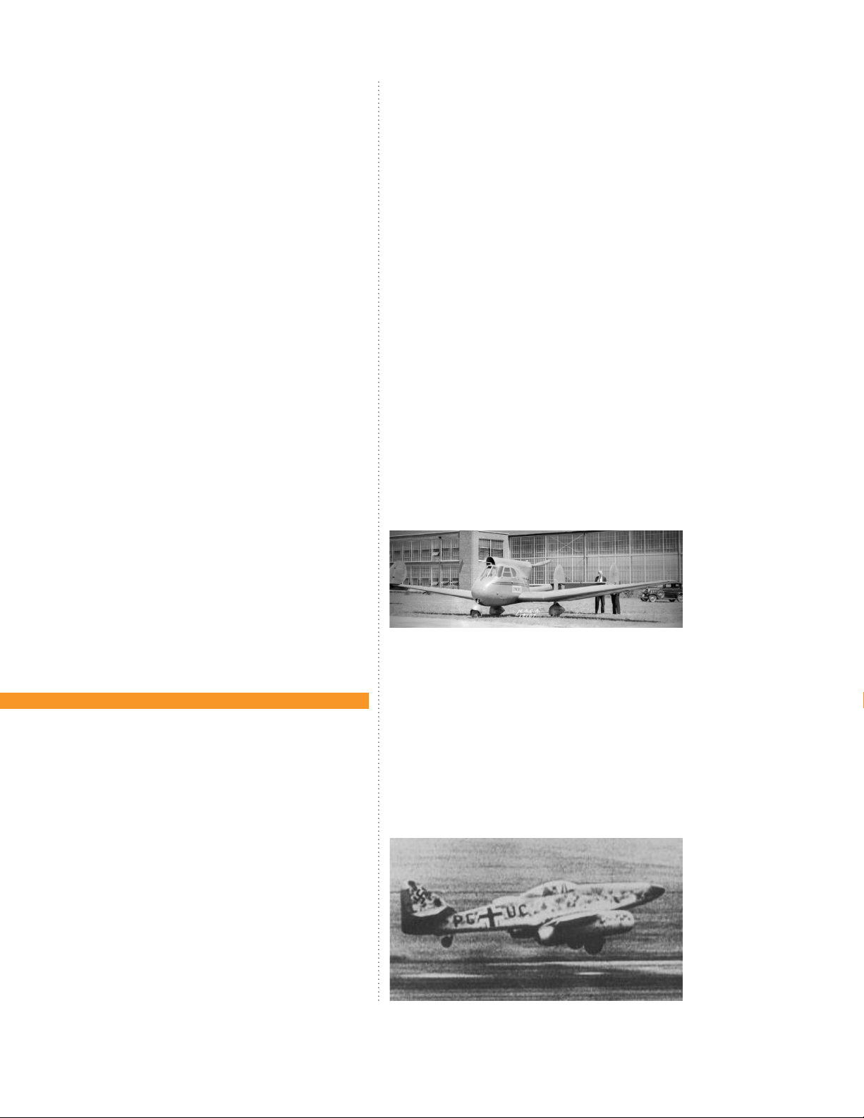
Photos of
the 1937-38
Luscomb 8a
nor overly challenging. Accordingly, it is one of the best
choices for both VFR and IFR training. With its high wing,
granting an unobstructed downwards view, it is ideal
for sightseeing, aerial photography and for patrol and
surveillance duties.
FBOs and flying clubs love 172s because there are
always excellent examples available in the market for
purchase/lease, they are reasonably priced, cost eective to operate, are durable, and if well-maintained,
hold their value well. Parts are plentiful and available
but, as it is with all aeroplanes, they may be expensive
depending upon which part(s) is/are needed. Pilots new
to the 172 find that they oer no unpleasant surprises,
are a quick study and require little time to check out in.
They have an excellent safety record, keeping hull and
liability insurance premiums to the minimum. They are
not fuel guzzlers and can withstand a lot of pilot abuse.
Renters find that they are not walletbusters, either.
On the debit side, 172s cabins are snug with limited shoulder and headroom for all but the smallest
and slightest people. “Full sized” adults will find them
an uncomfortable or even prohibitively small environment. Like many “four-seat” GA aeroplanes, the 172’s
average 900 lb. useful load does not permit full tanks
plus four hey adults on board. With standard tanks (43
gal.) on board, only 642 lbs. of available load remains.
Of course, if you and your friends weigh an average of
no more than 160 lbs. or so each, no worries. In the real
world (my world, anyway) this may not be the case.
172s are slow; there is no way around it. It’s a 120k
(138 m.p.h.) aeroplane and that is all. Fully loaded it
may climb at 600-700 fpm at sea level. The cabin is loud,
even at cruise settings the engine produces a distinctive and pervasive low-midrange drone that makes casual conversation in the air without an intercom system
somewhat diicult. However, from the “R” model forward, some attention to cabin soundproofing has been
addressed.
Of the 60K Cessna172/Skyhawks that have been built
since its debut in November 1955, more than 20,000 of
those which remain are based and flying in the United
States; the rest are scattered over virtually every corner
of the world.
THE RISE OF A CLASSIC AEROPLANE
So then, from where and whence did this ubiquitous
work horse of the general aviation fleet come?
Anyone seeking proof that evolution exists need look
no further than the Cessna 172. Its design is a mélange,
hybrid and accumulation of those designs of a number of
previously successful aeroplanes. Many histories of this
aeroplane start from the point when Cessna decided to put
a nose wheel on their popular 170 model; but that does
not go back far enough. It is clear that many of the specific
design characteristics of the 172 gradually took shape and
form from its immediate predecessors going back to just
aer World War II. The 172’s real forefathers are the humble
120/140/140A models, the elementary, 85-90 h.p., single
engine, high wing, two seat tail wheel aeroplanes which
came into this world in 1946 as part of the virtually univer
sally predicted General Aviation (GA) boom which so many
supposed would blossom and thrive aer World War II as a
matter of course, but which never happened.
You see, the makers of general aviation aeroplanes
thought and to be fair, not without sound reason, that
thousands of returning military pilots would be more
than anxious to jump at the chance of owning and flying
their own aeroplanes now that they had experienced
(on Uncle Sam’s dime, if you please) the “wonderful
world of flying”. Sounds good, right? Wrong.
The real story which the virtually drooling aer-war
aeroplane manufacturers did not ken was that for all
too many of these brave and valiant pilots their experiences in the air during the war ran from deadly dull to
just deadly; and with not much in between. Fortunately,
most service pilots’ closest brush with the Grim Reaper
-
8
A2ASIMULATIONS
:::
C172 MANUAL www.a2asimulations.com

whilst flying came from being bored to death on seemingly endless flights of all kinds in all kinds of turbulence
and rough weather during which their most ardent, fervent wish was to return safely, and soon to terra firma,
the more firma the less terra.
For those far fewer souls who found themselves,
mostly by o - regretted choice, in harms way at altitude, the experience of flying was mostly as described
by U. S. M. C. Colonel Gregory “Pappy” Boyington: “Flying is hours and hours of boredom sprinkled with a few
seconds of sheer terror.” Enough said.
So, between the recently bored and/or terrified exaeroplane jocks a far smaller realistic potential clientele for Pipers, Taylorcras, Cessnas, Stinsons and the
like than had been so optimistically imagined actually
existed. Still, aer the enthusiastic, if unrealistic, postwar glut on the market of various GA aircra types and
makes, a few managed to survive, some by virtue of the
brilliance of their design, most by virtue of the fact that
they were relatively inexpensive to own and operate.
In 1946, aviation fuel cost around US .20 per gallon
(worth approximately US$2.50 in 2013). This was not too
bad; better anyway than the just over US$6.00 for 100LL
in most places in the U.S. in 2013. In 1946, a brand new
Cessna 120 cost a bit over US$3,000.00 (worth approximately US$37,198.00 in 2013); just about the price of a
new, well-equipped BMW 3-Series 328i Sedan or Buick
LaCrosse Hybrid Sedan (before taxes, etc.) in 2013.
For comparison, in 2013 1946 Cessna 120s in
good condition were advertised for between a low of
US$17,000.00 and a high of US$30,000 depending upon
engine and propeller TBO, radios, etc. installed.
THE CESSNA 120/140 –WHERE IT BEGINS.
Piper, Taylorcra, Stinson and others had been producing light, two-seat, high wing aeroplanes before the war
slightly altering these aeroplanes for military use by the
services to great eect. Cessna, however, which had seen
its T-50 light twin used to great eect by the services as the
AT-17 multi-engine trainer as well as building 750 Waco CG4A-CE assault gliders of D-Day fame, had no similar light
single of its own at war’s end and therefore has to start
from scratch to catch up to the others. Looking around for
ideas, Cessna was sure to notice Don Luscomb’s excellent
1937 “8” series “Silvaire”, an aeroplane widely used in the
pre-war and wartime Civilian Pilot Training Program. (unimportant information: the very first aeroplane I ever flew
and trained in was a Luscomb 8A on floats). Numerous dis
tinct design similarities between the Luscomb 8 and the
120/140 are surely more than coincidental.
So, the great controversy continues; was the Cessna
120 a budget model of the 140, or was the 140 the deluxe model of the 120? While there are some distinct
dierences between them - the original 140 has flaps
(albeit somewhat questionable as to eectiveness),
and small “D” windows a of the main side windows, as
well as an electrical system which includes a starter - it
was not long before many 120s got retrofitted with, you
guessed it, “D” windows, an electrical system w/ starter,
and in some cases, flaps.
All original 120/140s had C-85 Continental four cylinder horizontally opposed engines and fixed-pitch propellers of the cruise (lower pitch) or climb (higher pitch)
variety.
As they came from the factory in 1946, the wings of
the Cessna 120/140 were fabric covered; however, most
-
www.a2asimulations.com C172 MANUAL
Photos of
the 1946
Cessna 120
:::
A2ASIMULATIONS
9

FOREWORD
1948 Cessna 140
have by now been since converted to metal covering.
Li struts extending from the bottom of the fuselage
to the wing s were of the “V” two-strut design. In 1948
the 140’s instrument panel was updated from the old
30’s/40’s central cluster (clutter?) to something resembling a useful layout.
THE CESSNA 140A – THE TRUE
ANCESTOR OF THE 172 EMERGES.
In 1949, disappointed by the poor sales and the short
customer lines of returning aviators (see above) Cessna
updated the 140 and the “A” model was introduced.
The fuselage and interior were le unchanged; however
some real aerodynamic improvements were included
such as an entirely new semi- tapered wing for better
roll response; and still a bit later, replacement of the
original thin-chord, ineectual flaps (which is why there
is little practical aeronautical dierence between the
120 and the 140) with slightly shorter but deeper real
Fowler flaps, which finally gave the 140’s flaps some authority.
(The Fowler type flap’s trailing edge flap extends
rearward of the wings as it descends on special tracks.
When deployed, wing area, camber and chord are increased and if there is a slot, or opening at the hinge line
to allow airflow over the top of the flap, boundary-layer
control may be improved. Fowlers provide the most li
per sq. . of surface of any type of flap; however, they
require a complicated linkage system and mechanism.)
At the same time that Fowler flaps were installed,
the powerplant was upgraded to the Continental C-90,
90 h.p. engine.
A big step on the way to the 172 was the new wing.
The fabric covering of the 140A’s original wing was replaced with a new design which was covered with
stressed aluminum, stiening the entire structure and
thus permitting a single li strut per wing rather than
the dual “V”, two-strut design of the 120/140. Additionally, the ailerons were lengthened and ran the length of
the tapered outer-wing section and the wing tips were
changed from rounded to what was thought to be a
more modern-looking squared o shape.
Also, the 140A received an improvement in its landing gear. The 1946 120/140s already had the familiar
Cessna flat spring leaf steel, main landing gear legs.
While the materials used and the exact design of
10
The 1950C-140A
A2ASIMULATIONS
:::
C172 MANUAL www.a2asimulations.com

1948 Cessna 170
Cessna’s landing gear legs have changed from steel
leaf to tapered tubular spring over time, their profile
and general appearance have remained essentially
unchanged. The 140A had toe brakes which were not
at all common in light aeroplanes at that time. Cessna
was afraid that pilots new to this kind of brake control
system would nose the 140A over too easily by braking
too hard. Accordingly, the main gear was moved forward to put the C. G. farther behind the main wheels.
Later, some 120s and 140s were retrofitted with landing gear extension modifications which moved their
wheels forward as well. Pilots being the myriad, multifarious, magpies that they are, some have managed to
nose over their 140As anyway.
Around 525 140As were built, including a few C140A “Patroller” types, anticipating the 1949 L-19 (O-1)
“Birddog”, a derivative of the C-170. The “Patroller” was
designed for use by police departments, who had vast
areas of highway to patrol, such as are found in and
around the deserts of the southwest U.S. They had seethrough Plexiglas doors, 42 gallon fuel tanks for long
range/long loitering time; and most curiously, a tube in
the floor which could ostensibly be utilised for dropping
messages and/or for more basic biological necessities.
The Cessna 140 has a special place in the hearts of
all of those (me) who were first introduced to the reality that we could actually go flying by the late and
much missed Frank Kingston Smith who, amongst his
many books and magazine articles, wrote the delightful
“Weekend Pilot”. Therein he tells of how as a much beleaguered young Philadelphia attorney in the mid 1950s
he almost succumbed to a depressing syndrome of ulcers and emotional dysfunction but for his accidental,
but literally life-saving and life-changing introduction to
and involvement with aviation. The airplane he bought
and learned to fly in was a Cessna 140.
The Cessna 120/140 is one of the most gentle and
forgiving of the classic tailwheel aeroplanes; however,
interestingly (balingly), a few 140As have been spotted
with nose wheel conversions, turning them into sort-of
Cessna 150s. Most ironically, there are and have been
for some time a number of companies oering a tailwheel conversion for the Cessna 150/152 turning them
into sort-of Cessna 140A’s! Madness, I say; madness.
THE CESSNA 170 – GETTING
CLOSER TO HOME.
Given the time it takes for design development and prototype testing, the C-170, introduced to the public on 27
February 1948, a year before the debut of the C-140A,
it is clear that as early as 1947 that Cessna was already
committed to producing a four-seat version of their
120/140 models.
Like the 120/140, the new C-170 was initially produced with an all-metal fuselage and fabric-covered
wings which had no dihedral and were called “straightwings”. The fin/rudder had no dorsal fin. The engine was
upgraded to the reliable flat, six-cylinder, horizontally
opposed 145hp Continental C-145-2 (later the O -300A)
with three of the C-140’s fuel tanks totaling 42 US gallons installed in the wings to accommodate the larger
engine. The li struts were the same “V”, two- strut design as on the 120/140. In every way, this new aeroplane
was just a slightly larger 120/140; but changes were to
come soon which would transform this aeroplane into
the father of the 172.
www.a2asimulations.com C172 MANUAL
:::
A2ASIMULATIONS
11

FOREWORD
Photos of 1950
Cessna 170A
THE CESSNA 170A - ARE WE THERE YET?
There is every reason to suspect that the initial C-170
was a temporary and somewhat hastily produced
aeroplane because before the year was out, Cessna
introduced the much slicker and more sophisticated
C-170A. The fin/rudder now had a dorsal fin and was
identical to that of the already established C-190/195
aircra which were introduced in 1947. This aero
plane sported a new wing, now covered with metal
and with slightly larger flaps. While these flaps were
not yet the more eective “Fowler” flaps to come on
the C-170B, they could be lowered to a whopping
50º! Like the C-170’s wing, this new wing had no dihe
dral; accordingly, the C-170 and C-170A are called the
“straight-wing” 170s.
In 1952 the pen-ultimate variant of the 170, the C170B was introduced and production of this aeroplane
continued until 1956, the year of the first C-172. The C170B was a massive and distinct refinement of the 170
model and set the stage for all of the subsequent C-172
s which were soon to begin to appear.
Larger “Fowler” flaps, first seen on the C-140A and
which were also used on the L-19 ‘Birddog” introduced
in 1950 were installed in the C-170B’s new wing. These
were termed “Para-Li flaps” by Cessna, but are more
commonly called “barn door flaps”. They initially could
be lowered to 20º, 30º and 40º; however, beginning in
1955 an additional 10º flap setting for short-field takeos was added.
Other aerodynamic refinements included a newly
designed stabilizer/elevator with an increased aerodynamic balance area at the tips which incorporated
within them an internal mass balance which reduced elevator control pressure. Also, in 1955, the rounded rear
side windows were changed to be more square shaped,
and a new, more durable type of tailwheel bracket was
installed.
All of these refinements much improved the C-170;
however the most significant and longest lasting refinement was the wing. The “B”’s new wing became the
-
standard wing of all Cessna light single-engine aircra,
including the C-172, and is still incorporated to this day.
The wing incorporated all of the previous refinements
such as a stressed- skin metal covering, etc., and consists
of a constant 64” chord NACA 2412 centre section from
-
centerline outward to 100”, at that point tapering to 44-
12
A2ASIMULATIONS
:::
C172 MANUAL www.a2asimulations.com

inch chord NACA 2412 section at 208” from centerline.
This new wing also now had 3º of dihedral with threeº
washout (forward twist) across the tapered section only
to prevent wing-tip from stalling before the wing-root.
All of these refinements were carried over to the C-172
and have appeared on all subsequent 172 models. The
172 was now only one step away from birth.
THE CESSNA 170C – ALMOST THERE, KIDS.
In January 1955, while the scene was set and lit and the
curtain seemed just about ready to rise on the Cessna
172, there was one more slight detour; the C-170C. Not
quite ready to abandon its latest and most successful
aeroplane, Cessna modified the C-170 one more time
creating the C-170C. The 145 hp
Continental C-145-2 engine used
in all previous C-170s was replaced
with the more modern flat six-cylinder, horizontally opposed, Continental 0-300-A. The O-300 is essentially a modernized C-145 and
has the same dimensions, weight,
bore, stroke, displacement, compression ratio and output. Both
the C-145 and O-300 use a direct,
un-geared drive to the propeller
and produce approximately 145
h.p. Many pilots appreciate and
are pleased by the smoothness of
the six-cylinder O-300, but are less
than pleased at their increased
overhaul bill caused by the extra
two cylinders.
The tail surfaces were once
again revised to incorporate an
even larger stabilizer/elevator (still
with the same aerodynamic and
mass balances of the C-170B) and
a very businesslike, “modern” squared-o fin/rudder.
This became the C-172’s tail section.
While this aeroplane was promoted as the latest and
the greatest of the C-170 series, Cessna had a trick card
up its sleeve, and it was an ace. On 12 June 1955, Cessna
unveiled what it had undoubtedly been working on for
a long time -- the first tricycle gear Cessna -- the C-170C
now had a nosewheel!
The 170’s FAA type certificate initially included an
additional provision for a “C-172” , which was done to
reduce usual bureaucratic certification time and fees.
Aer overwhelming approval of the tricycle geared 170
by the aviation community, a separate type certificate
was applied for and received for the new Cessna 172.
TOP: Photo of
1952 C-170B
BOTTOM LEFT: Photo
of early 1960’s era
Army L-19 Birddog
BOTTOM RIGHT: Photo
of Vietnam-era Air
Force L-19/0-1 Birddog
Photos of 1955
Cessna 170C
www.a2asimulations.com C172 MANUAL
:::
A2ASIMULATIONS
13

FOREWORD
1955 Cessna 172
14
THE CESSNA 172/SKYHAWK
- HOME AT LAST.
“Everything old is new again.”
The early to mid -1950’s were yet another in the long
series of periods of change in aviation since the Brothers started the whole shabang at Kitty Hawk on a frigid
morning on December 17, 1903. It sometimes seems
that there are no periods other than periods of change
in aviation; but no matter. This time the big change was
from GA aircra with tailwheels to those with nosewheels.
tiss pushers of the early 1900s most presciently sported
tricycle landing gear, i.e., having a wheel at the nose
instead of one at the tail, that particular landing gear
A2ASIMULATIONS
configuration was diicult to design into an airframe
where the engine and its systems take up virtually all
of the available space in the very front of the fuselage.
The first military aircra with a nosewheel produced in
large numbers is believed by this author to have been
the Consolidated PBY “Catalina” amphibious light
bomber/patrol aircra, which first flew in March, 1935.
However, there was an even earlier GA aeroplane with a
nosewheel (aer the early Curtiss’), the W-1 designed by
Fred Weick and flown in 1934. Other early GA aeroplanes
with a nosewheel were the Stearman-Hammond Y-1 of
1936, followed by another, more famous Fred Weick de-
While some of the pioneering and innovative Cur-
:::
C172 MANUAL www.a2asimulations.com
sign, the “Ercoupe” first flown in October. 1937.
By 1938 aer thousands of expensive and sometime
fatal nose - overs of their tailwheel aircra, the U. S.
Army Air Corps was ready to try a new idea in a military
Early nosewheeled aircraft:
▶ Replica 1910
Curtiss “Pusher”
▶ W.W. II era Consolidated
PBY”Catalina”
▶ 1934 Weick W-1
▶ 1936 Stearman-
Hammond Y-1
▶ 1937 Weick (Forney)
“Ercoupe”
▶ An early Me-262
aeroplane; it was ready for aeroplanes with nose wheels
and the beginning of a new era in aviation commenced.
What followed were the P-38 “Lightning” -27 Jan. 1939;
the P-39 “Airacobra” -April, 1939; the B-24 “Liberator”mid-1939 (the first A. A. C. bomber with a nosewheel, the
B-17 being the last A. A. C. bomber without one); B-25
“Mitchell” - late 1939; the B-26 “Marauder”-Nov. 1940.
Of course, once the jet-age began, tailwheels were as
useful as…well, whatever is not very useful (although,
interestingly, the first operational jet fighter, the Messerschmitt Me-262 was first designed and test - flown with
conventional tailwheel landing gear).
Aer World War II makers of GA aircra soon followed
the lead of the military. In 1951 Piper introduced its it’s
first tricycle landing gear aeroplane, the four-seat PA-22
Tri-Pacer. It was a huge success and it surely challenged
www.a2asimulations.com C172 MANUAL
:::
A2ASIMULATIONS
15

FOREWORD
1951 Piper “Tripacer”
and tasked Cessna to step up and to introduce a tricycle
geared aeroplane of its own. Additionally, the impetus
for Cessna to produce a factory tri - gear 170 possibly
came because of the well - known tri - gear STC (Supplemental Type Certificate) for the 172 developed by MetCo-Air in Fullerton, California, a modification which was
being made by many C-170 owners.
In July 1955 the aeroplane destined to become one
of the most beloved in its class, the Cessna 172, was introduced to the public, touted to now be equipped with
“Land - O - Matic” (tri - cycle) landing gear. An overnight
sales success, more than 1,400 were built and sold during the first year aer its unveiling. Cessnas all-metal
and far sleeker - appearing entry into the tri - gear race
was more appealing to many than the fabric - covered,
and to many stodgy and foreshortened - looking Piper
Tri - Pacer.
Aer the C-172’s appearance and huge success, the
GA “nosewheel revolution” continued throughout the
rest of the ‘50s and into the 60’s until very few GA aircra, except for special types intended for aerobatics,
crop dusting, bush and rough country flying and other
specific utility purposes were still being manufactured
with tailwheels.
1960 saw a new swept - back tail on the C-172A
which looked rakish, but didn’t actually increase performance in any way. In 1961 the first C-172 was available as a “Skyhawk”, an upscale, more luxurious version of the C-172B. However, aer a short while, all
C-172s were popularly called “Skyhawks” and the distinction gradually dissolved until 1977, when all C-172s
were then and thereaer oicially and simply named
“Skyhawks”.
A major change in the fuselage structure and in
the overall appearance of the C-172/Skyhawk came in
1963, one year aer the same modification was made
Photo of 1961
C-172A/Skyhawk
Cessna 172/Skyhawk
w/ new fuselage
16
A2ASIMULATIONS
:::
C172 MANUAL www.a2asimulations.com

to the C-182 and to Cessna’s single-engine flagship, the
C-210 with the dropped rear fuselage and inclusion of
a wraparound rear-view window. Not being an aeroplane likely to ever be involved in aerial combat, unobstructed vision to the rear might be seen by some as
being somewhat superfluous in the 172; but it looked
modern, added welcome light and a feeling of extra
spaciousness to what is in the fastback versions of the
aeroplane a fairly cramped and formerly claustrophobic environment.
While the original C-172 evolved and was altered
over the years as to its appearance (swept fin/rudder,
rear view window), available equipment, electronics,
soundproofing, landing gear length and construction,
control refinements, engine swops, experiments with
cantilever wings, retractable landing gear, as well as
plans for diesel and electric power; it has always remained what it was from the first: a reliable, utilitarian
and good- mannered flying machine for four moderately sized people to fly for moderate distances at moderate altitudes and airspeeds.
Not an aeroplane which exhibits spectacular performance numbers, the C-172 nevertheless just keeps on
doing what it has done from the first, which is to provide the ordinary private pilot with an excellent, if most
moderate way to go aviating; and you know, sometimes
moderation is the wisest practice aer all, which during
its 43 years and counting, the ever-popular Cessna 172
has well and truly proved.
1959 Cessna 175/Skylark
Photo of 1957
Cessna 180
SIBLINGS AND RELATIONS
THE CESSNA 175/SKYLARK
By 1958, the popularity and commercial success of
the C-172/Skyhawk was firmly established. Cessna
perceived that there was market for a more powerful
C-172 but was unwilling to risk its star seller’s reputation and “brand” recognition by going too far in altering the basic design. Accordingly a new Cessna, the
C-175 was developed.
Intended to take its place between the heavier and
more powerful Cessna 180 and the C-172/Skyhawk, the
C-175 and the “Skylark”, a more luxurious version, was
intended to be both close enough and dierent enough
to the “Skyhawk” to maintain a familial connection. The
powerplant chosen was the Continental GO-300 which
is a geared and beefed up 175 h.p. version of the 145 h.p.
Continental C-145 engine which powered the Skyhawk.
This turned out to be a poor choice of engine. Because
it is essentially a 145 h.p. engine pushed to put out 30
more horsepower by gearing the propeller, its TBO (time
between overhaul) is only 1,200 hours of operation,
whist the un-geared C-145 (O-300)’s TBO is within the
industry standard at 1,800 hours.
While there are a number of structural details that
dier from the C-172/Skyhawk to accommodate its
greater power and weight, the C-175/Skylark looks
much like the C-172/Skyhawk, except for a distinct
bulge in the cowling to make room for the rather large
and bulky engine gear box. This at least makes the
C-175/Skylark an excellent choice for a rather tricky
“name that plane” contest.
The C-175/Skylark was not a successful aeroplane for
Cessna. Firstly, it did not much improve the C-172/Skyhawk’s performance all that much. Those who desired
the spectacular and legendary performance of a C-180
simply chose it instead, and those who desired a C-180
with tricycle gear chose the C-182/Skylane. Secondly,
the C-175/Skylark’s ill-starred GO-300 engine was, perhaps hastily and unfairly perceived to be unreliable,
possibly because of its low TBO, and accordingly the
C-175/Skylark was largely ignored. Eventually realising
that it had clearly made a serious marketing mistake,
Cessna wisely dropped the aeroplane from its production lines aer only four years of tepid sales.
THE CESSNA REIMS - FR172J “REIMS ROCKET”
Built in the mid ‘60s through the mid ‘70s by the
French aviation company known alternatively as “So
cietè Nouvelle Max Holste, and “Reims Aviation”, the
pleasantly named FR172J “Reims Rocket” is essen
tially a heavily modified C-172F. Reims Aviation also
produced modifications of other Cessna aircra: F150
, F152, F172, F177, F182, F337, and the Reims-Cessna
F406 “Caravan”.
-
-
www.a2asimulations.com C172 MANUAL
:::
A2ASIMULATIONS
17

FOREWORD
The Rocket was powered by a fuel-injected, Continental IO-360D of 210h.p. (takeo), 195 h.p. (continuous) which was built by Rolls Royce, with a constant
speed, controllable propeller, which is also basically the
same powerplant that is installed in the twin-engined
Cessna 336/337 series.
It was the first 172 to have electrically operated
flaps instead of the former manual, lever-operated
flaps (which I personally like a lot better). The Re
ims Rocket was the prototype aircra for the further
1972 Cessna “Reims Rocket
1965 T-41A,B “Mescalero”
modified U. S. A. F. T-41A “Mescalero” primary trainer
(see below).
THE T-41A,B “MESCALERO” – U.S.
AIR FORCE PRIMARY TRAINER
In 1964 the U.S. Air Force chose the C-172A to be the
aeroplane used for Undergraduate Pilot Training (UPT),
later called Initial Military Flight Screening (IMFS) air-
-
cra, naming it the T-41A. The Air Force rightly figured
that if a prospective Flight Training Cadet could not
learn to fly this most docile and forgiving aeroplane in
a fairly short time, then he or she was not a likely candidate for their most rigourous flight - training program, of
which your author has some practical knowledge.
The T-41A “Mescalero”, named aer the “Mescalero
Apache” tribe of New Mexico, was initially a stock 172.
The following year the Air Force, influenced by the increased performance of the Cessna Reims - FR172J “Reims Rocket”, modified the T-41A with the installation of
the same 210h.p. (takeo), 195 h.p. (continuous) Continental IO-360 engine, with a constant-speed controllable propeller in place of the stock 145hp Continental
O-300 and its 7654 fixed-pitch propeller, as was installed
in the factory C-172A. This was the T-41B.
Additionally, in 1968 the U. S. Air Force acquired 52 T41Cs, which had the same engine as the T-41B but with
a fixed-pitch climb propeller for the Air Force Academy
in Colorado Springs, Colorado, a climb propeller being most useful in that largely vertical territory. Three
of these remain at the school and are used by, among
others, the Academy’s prestigious show -flying team. A
later “D” model of this aeroplane included more sophisticated avionics including a proprietary military TACAN
(Tactical Air Navigation System) receiver; essentially a
hyper-accurate VOR/DME.
The T-41 in its various incarnations was the U.S. Air
Force’s Initial Military Flight Screening (IMFS) aircra
until 1993, when it was gradually phased out in place
of the ill-fated and too-occasionally deadly Slingsby
T-3A Firefly. The Air Force has since utilised the Diamond
DA20 for this purpose.
1980 R172K Hawk
XP on oats
18
A2ASIMULATIONS
R172K HAWK XP
Built both in Wichita and Reims between 1977 and ’81,
had a fuel injected, Continental IO-360K (IO-360KB) a
210 h.p. engine which was soon derated to 195 h.p. to
increase its TBO from 1,500 hours in 1977/ early ’78 to
2,000 hours thereaer, with a constant speed, controllable propeller. The Hawk XP was basically Cessna’s
homegrown answer to the French Reims Rocket and
could cruise at 131 knots as opposed to the plain-jane
172’s 120 k cruise. This slight increase in speed was not
considered by some to be worth the extra purchase
price and operating costs.
However, the one place that the R172K Hawk XP really shines is on the water. A standard 172 is not powerful enough to be an eective four-passenger floatplane;
:::
C172 MANUAL www.a2asimulations.com

Photos of 1980 Cessna
172RG “Cutlass
however, the Hawk XP on floats is one of GA’s nicest
four-seat floatplanes, with its excellent takeo performance and cruise speed of around 125K, which is very
good for a floatplane in its class. (more unimportant information; I oen flew a Hawk yea’ years ago from the
old, now long gone and much missed “Suburban Seaplane Base” in Island Park, N.Y., located near the Long
Beach /Island Park Bridge; and it was a class act with
lots of get up and go).
the 120 knot C-172 go faster. To do so cost US$19,000
more than the standard 172 so that the landing gear
would get out of the way of the oncoming air. How
ever, at the end of the day, the RG’s best cruise speed
is only 140 knots compared to the 120 or so knots
cruise of the standard and much less expensive 172.
The extra expense of purchase, maintenance and an
nual inspection of a C-172 with retractable gear was
not greeted with enthusiasm by many. Additionally,
for some, the idea of an aeroplane with wing struts
THE CESSNA 172RG “CUTLASS”
Sometimes humourously (or maybe, not so humourously) called the 172 “RRR” (Pirates, Cutlass…whatever), the “RG” stands for the fact that this 172’s
landing gear retracts. Introduced in 1980 and actually
appearing on the Cessna 175’s FAA type certificate,
the 172 RG is oicially considered to be a variant of
the C-175 and not of the C-172. It is powered by the
venerable Lycoming O-360-F1A6 engine of 180 h.p.
(also the familiar powerplant of the Piper “Coman
che 180”, “Archer” and many others), with a constantspeed, controllable propeller. The idea was to make
www.a2asimulations.com C172 MANUAL
hanging out in the breeze and retractable gear seems
and looks preposterous, and perhaps it is.
In any event, the C-172RG was a case of not enough
go for the buck; and, accordingly, it did not find much
favour in the mass GA market. The beginning of a worldwide slump in new GA aircra sales in 1980 didn’t help,
either. The RG found a small niche for itself, however, in
flight schools which found it to be a relatively low-cost
aeroplane for giving pilots the requisite complex aircra
-
(controllable propeller - retractable landing gear) experience necessary to obtain a Commercial Pilot’s Certificate in the U.S.
-
-
:::
A2ASIMULATIONS
19
FOREWORD
NOTEWORTHY FLIGHTS
LONGEST TIME IN THE AIR
WORLD’S RECORD FLIGHT
As part of a clever and spectacular fund- raising scheme
for the Damon Runyon Cancer Fund, Robert Timm and
John Cook took o from McCarran Airfield, Las Vegas, NV
in Cessna 172 N9172B on December 4, 1958. What was
dierent and newsworthy about this particular takeo
was that the next landing did not occur until 64 days, 22
hours, 19 minutes and 5 seconds had elapsed when they
landed back at McCarran Airfield on February 4, 1959.
Timm and Cook pulled up all personal necessaries,
such as food, water with buckets on ropes and through
the specially made accordion door on the passenger’s
side from a truck, which drove at full throttle down a
long, straight road with the Cessna flying overhead and
matching its speed. Fuel was taken on board through a
hose, which first fed a special auxiliary fuel tank in the
belly of the aeroplane which, in turn, fed the two wing
tanks. Extra oil was carried on board and fed to the engine through a hole in the instrument panel and firewall.
To accommodate all those cans of oil and other living necessaries, there was only room in the snug and
crowded cabin for the pilot’s seat. A so, roll-up pad
was used as sleeping accommodations for the pilot not
on duty.
Problems arose early in the flight when the electric
generator, which was driven by the engine, failed. Undaunted by this setback, the innovative Timm and Cook
called for and hauled up a wind - driven generator from
an Aeronca Champion, duct-taped it to the right wing
strut and plugged it into the aeroplane’s cigarette lighter receptacle, thereby providing electric power for the
remainder of the flight, which went without a further
hitch.
Once they knew that they had broken the world’s
record for endurance in flight, the pilots wisely decided
to end their flight as their faithful Cessna’s beleaguered
and tired engine was, aer over 1,500 hours of continuous operation, starting to lose power. Near the end of
the flight, the exhausted 172 could hardly climb away
aer refueling and before all ended in tragedy, the time
to call it quits was clearly on hand.
This world’s record breaking Cessna 172 can be seen
on display in the passenger terminal at McCarran International Airport, Las Vegas, Nevada.
TO RUSSIA WITH LOVE
On 28 May 1987 at approximately 7:00 p.m., 18 (or possibly 19) year - old Mathias Rust, a German pilot with
only around 50 hours of flight experience, flew a rented
German - registered Reims Cessna F172P, D-ECJB from
Helsinki-Malmi Airport through Soviet airspace to a
landing on a bridge near St. Basil’s Cathedral in Red
Square, Moscow, U. S. S. R. Rust was detected by but not
stopped by Soviet air defense forces.
As it happens, Mr. Rust was luckier than he could
have hoped for in that the overhead electric trolly wires
that usually run along and above the bridge were under repair and had been taken down on the morning
of the day he landed there and were replaced the next
day. Aer a successful landing, Rust then taxied o the
bridge, past the famous Cathedral and came to a stop
about 100 metres from the entrance to Red Square. His
20
A2ASIMULATIONS
:::
C172 MANUAL www.a2asimulations.com

approach and landing was videotaped by a British doctor. Rust was promptly arrested, tried and sentenced to
4 years in a labour camp. However, he did not actually
serve out his sentence in a labour camp, but instead at
the far less rigourous high security Lefortovo temporary
detention facility in Moscow. Rust had served less than
one year of his sentence, when he was released by order
of General Secretary Mikhail Gorbachev in August 1988
as a gesture of good will to the west.
YOUR CESSNA 172R SKYHAWK
This is the aeroplane that almost never was. In fact, there
almost were never any more light Cessna aeroplanes
built aer 1985. In the mid 1980s, the economy in the
United States was in very bad shape, something we know
all about again today. Also, a spate of what some might
consider unwise, unreasonable and draconian decisions
by various courts regarding product liability had crippled
manufacturers of light aircra such as Cessna and had
rendered their businesses untenable. Accordingly, unable to thrive in such a hostile insurance climate, Cessna
simply closed up shop. Almost ten years went by, but in
1994 President Clinton signed the General Aviation Revitalization Act, which eased and limited the manufacturer’s liability with regard to accidents in which there
occurred monetary or property damage and/or personal
injury as a result of the operations of a light GA aeroplane.
The result was that in 1995, a new C-172, the “R”
model would be produced. This new 172 was an improvement over the last 172, the “N”, built in 1985, in
that the “R” has the larger fuel injected Textron Lycoming IO-360-L2A engine. The last 172, the “N” had the
smaller, carburetted Lycoming O-320. This Lyc 360 was
de-rated from its usual average 180 h.p. to produce
only 160 h.p., which means that it lasts longer and has
a greater TBO. Also, the injected Lyc I0-360 produces
maximum power at only 2,400 r.p.m. ,making it quieter
and more fuel eicient than the faster- turning Lyc 320.
The “R” got a complete interior make-over with vertically adjustable, contoured, reclining, 26g seats and
an inertia-reel seat belt/harnesses (a responsive echo
from the old product liability lawsuits), an eicient
multi-level ventilation system (always an important feature for flight simmers), an intercom system for all four
seats, and extensive soundproofing which was sorely
needed in the aeroplane’s previously overly-loud interior environment.
Structurally, the “R” received stainless steel control
cables, dual vacuum pumps, epoxy corrosion protection, larger fuel tanks, tinted windows, better, back-lit,
non-glare instruments, a systems annunciator panel,
optional wheel fairings, and more radio package choices including GPS or IFR GPS.
An upgraded version, the 172S Skyhawk SP was offered in 1998 with the full-power Lyc IO-360 rated at 180
h.p., a larger propeller and a leather interior.
Not a generic “C-172”, A2A has specifically modelled
every aspect of the C-172R in every detail using the tremendous amounts of information of all kinds which
were derived from the pilots on our sta’s extensive
real-world flying of an excellent example of the Cessna
172R. Taking all of that information, we modelled the
most authentic and accurate flight-sim Cessna 172R
available, both visually and in its flight characteristics.
We do this because we have a passion for flying which
we want to share with you. Enjoy!
www.a2asimulations.com C172 MANUAL
:::
A2ASIMULATIONS
21

DESIGNER’S NOTES
VER TEN YEARS ago, A2A (then Shockwave
Productions) entered the flight simulation
scene with strong opinions of what was
needed in our flight simulation industry.
O
And thus, began our quest to unwind and
re-define what the word “simulation” truly
means. Today and over a decade later, we
have released a new airplane, the Accu-Sim
C172 Trainer. This is one of our most ambi
tious and important projects to date.
-
22
A2ASIMULATIONS
:::
C172 MANUAL www.a2asimulations.com

The month preceding the public release of this aircra brought a new challenge, and that was “how do we
show our customers what this product is?” Everywhere
we look, we see brand new substance. While the Cessna
172 is a simple aircra to operate, reproducing and simulating all of the building blocks of this machine is not.
The conversations we’ve been having with many companies and people in aviation were dierent than most
were used too, because here comes this ambitious company A2A having to understand aspects of an airplane
that pilots, mechanics, and even many engineers don’t
have to know. But we do, because we must produce the
exact same product in a dierent world. The wonderful
and magical world of flight simulation.
Soon you will be reading and possibly participating
in discussions within our simulation community that
are virtually identical to the conversations taking place
right now throughout the aviation communities, with
questions like “what oil do you recommend during the
winter months?” “How do you like that propeller?” “Do
you lean your engine by ear or using the EGT gauge (exhaust gas temperature)?”
Your Accu-Sim airplane has been developed as we
go back and forth from the airport to our development
workstations. Not only does the aircra and its systems
persist from flight to flight, even engine temperatures
persist. So if you land at an airport on a cold day, park
the plane, turn your computer o, grab lunch and return
an hour later, you will find an engine that is still warm.
If you wait until the next morning to fly, it will be what
is known as “cold soaked.” However, if you plugged in
your electric engine heater you can come back anytime
and find a nice, warm engine waiting for you. Warm up
times will be much shorter, and your engine will actually last longer. This is what aircra owners talk about,
and do.
However, probably the most ambitious new feature in
the Accu-Sim C172 Trainer is the Pre-Flight Inspection (a
virtual walk-around). You can now, more than ever, visually see the state of the airplane. You can check for water
in the fuel, inspect various hinges, check the oil, tires, and
even wiggle the flaps by hand to see how secure they are.
In fact, this walk around system is so complete, that we
could hand this product to a future pilot who has never
even gotten close to a Cessna 172 and a week later, ask
him or her to perform a pre-flight inspection on the real
aircra. The result would be a person with a solid understanding of what parts and systems need to be checked
and why, and this would have all been learned without
realizing it since it was, in this case, interactive and fun.
“Fun” is a key word to learning and has been the core
of Accu-Sim since its inception. To be truly immersed in a
simulation, is to truly have fun. This is who we are, flight
simmers. We block out the world around us and want to
get ourselves lost in an alternate reality. This is simulation. But it must be true. When you do something as
simple as turn an ignition key and engage a starter, there
are things you can expect to happen…. physical things.
Much of our interpretation of the physical world around
us is known to us, subconsciously. We instinctively know
when something looks and feel right and conversely,
when something “just doesn’t seem right.” During our
development of our Accu-Sim aircra, we are continually
looking, probing, and testing all kinds of combinations of
things to make sure the physical world in Accu-Sim is as
true as we can make it to the natural world we all live in.
Pilots and aircra enthusiasts are a discerning, sensitive bunch. We’re tough to please, which helps define
who we are. We welcome everyone to the new AccuSim C172 Trainer. We hope you get not just hours, but
months if not years of growth and enjoyment from it.
THE AIR TO AIR SIMULATIONS TEAM
www.a2asimulations.com C172 MANUAL
:::
A2ASIMULATIONS
23

FEATURES
24
A2ASIMULATIONS
What you can expect from your
A2A Accu-Sim C172 Trainer.
:::
C172 MANUAL www.a2asimulations.com

Experience one of the world’s most
popular trainer airplanes.
Pure3D Instrumentation now with natural 3D
appearance with exceptional performance.
Designed for both professional commer-
cial pilot training and entertainment.
Immersive pre-flight inspection system designed
by pilots while operating the actual Cessna 172.
A true propeller simulation.
Electric starter with accurate cranking power.
Dynamic ground physics including both
hard pavement and soft grass modeling.
Primer-only starts are now possible. Accu-Sim
monitors the amount of fuel injected and it’s
effectiveness to start and run the engine.
Persistent airplane where systems, cor-
rosion, and temperatures are simulated even when the computer is off.
Immersive in-cockpit, physics-driven sound
environment from A2A engineered recordings.
Complete maintenance hangar inter-
nal systems and detailed engine tests
including compression checks.
Piston combustion engine modeling. Air comes
in, it mixes with fuel and ignites, parts move,
heat up, and all work in harmony to produce the
wonderful sound of a Lycoming 360 engine. Now
the gauges look beneath the skin of your aircraft
and show you what Accu-Sim is all about.
A total audible cockpit and ound engi-
neered by A2A sound professionals.
In cockpit pilot’s map for handy
in-flight navigation.
Authentic fuel delivery includes prim-
ing and proper mixture behavior. Mixture can be tuned by the book using
the EGT or by ear. It’s your choice.
All models include A2A specialized materials
with authentic metals, plastics, and rubber.
Airflow, density and its temperature not
only affect the way your aircraft flies, but
how the internal systems operate.
Real-world conditions affect system condi-
tions, including engine temperatures.
Spark plugs can clog and eventually foul if
the engine is allowed to idle too low for too
long. Throttling up an engine with oil-soaked
spark plugs can help clear them out.
Overheating can cause scoring of cylinder head
walls which could ultimately lead to failure
if warnings are ignored and overly abused
Engine, airframe, cockpit panel and individual
gauges tremble from the combustion engine.
Authentic drag from the airframe and flaps
Authentic Bendix King Avionics stack includ-
ing the KMA 26 Audio Panel, two KX 155A
NAV/COMMS, KR 87 ADF, KT 76C Transponder, KN 62A DME, and K AP 140 Two Axis
Autopilot with altitude pre-selection.
Three in-sim avionics configurations including
no GPS, GPS 295, or the GNS 400. Built-in, automatic support for 3rd party GNS 430 and 530.
As with every A2A aircraft, it is gorgeously con-
structed, inside and out, down to the last rivet.
System failures, including flaps that can
independently jam or break based on the
actual forces put upon them. If you deploy
your flaps at too high a speed, you could find
yourself in a very dangerous situation.
Authentic battery. The battery capac-
ity is based on temperature. The major
draw comes from engine starting.
Oil pressure system is affected by oil vis-
cosity (oil thickness). Oil viscosity is affected by oil temperature. Now when you
Designed and built to be flown “By The Book.”
Visual Real-Time Load Manager, with the ability
to load fuel, people, and baggage in real-time.
Four naturally animated passengers that
can sit in any seat including the pilot’s.
start the engine, you need to be careful to give the engine time to warm
Eight commercial aviation sponsors have
supported the project including Phillips 66 Aviation, Champion Aerospace,
and Knots2u speed modifications.
3D Lights ‘M’ (built directly into the model).
www.a2asimulations.com C172 MANUAL
:::
A2ASIMULATIONS
25

QUICK-START GUIDE
Everything you need to get cleared
for take-off as soon as possible.
26
A2ASIMULATIONS
:::
C172 MANUAL www.a2asimulations.com

HANCES ARE, IF you are reading this
manual, you have properly installed
the A2A Accu-Sim C172 Trainer. However, in the interest of customer support,
C
here is a brief description of the setup
process, system requirements, and a
quick start guide to get you up quickly
and eiciently in your new aircra.
SYSTEM REQUIREMENTS
The A2A Simulations Accu-Sim C172
Trainer requires the following to run:
▶ Requires licensed copy of
Lockheed Martin Prepar3D
▶ Service Pack 2 (SP2) required
NOTE: while the A2A Accu-Sim C172 Trainer may work
with SP1 or earlier, many of the features may not work
correctly, if at all. We cannot attest to the accuracy of
the flight model or aircra systems under such condi
tions, as it was built using the SP2 SDK. Only Service
Pack 2 is required. The Acceleration expansion pack is
fully supported but is NOT REQUIRED.
-
OPERATING SYSTEM:
▶ Windows XP SP2
▶ Windows Vista
▶ Windows 7
▶ Windows 8
PROCESSOR:
▶ 2.0 GHz single core processor (3.0GHz and/or
multiple core processor or better recommended)
HARD DRIVE:
▶ 250MB of hard drive space or better
VIDEO CARD:
▶ DirectX 9 compliant video card with at least 128
MB video ram (512 MB or more recommended)
OTHER:
▶ DirectX 9 hardware compatibility and audio
card with speakers and/or headphones
www.a2asimulations.com C172 MANUAL
:::
A2ASIMULATIONS
27

QUICK-START GUIDE
INSTALLATION
Included in your downloaded
zipped (.zip) file, which you should
have been given a link to download
aer purchase, is an executable
(.exe) file which, when accessed,
contains the automatic installer for
the soware.
To install, double click on the executable and follow the steps provided in the installer soware. Once
complete, you will be prompted
that installation is finished.
IMPORTANT: If you have Microso Se-
curity Essentials installed, be sure to
make an exception for Lockheed Mar
tin Prepar3D as shown on the right.
REALISM SETTINGS
The A2A Simulations Accu-Sim C172
Trainer was built to a very high degree of realism and accuracy. Because of this, it was developed using
the highest realism settings available in Lockheed Martin Prepar3D.
The following settings are recommended to provide the most accurate depiction of the flight model.
Without these settings, certain features may not work correctly and
the flight model will not perform accurately. The figure below depicts
the recommended realism settings
for the A2A Accu-Sim C172 Trainer.
-
FLIGHT MODEL
To achieve the highest degree of realism, move all sliders to the right. The
model was developed in this manner,
thus we cannot attest to the accuracy
of the model if these sliders are not
set as shown above. The only excep
tion would be “Crash tolerance.”
INSTRUMENTS AND LIGHTS
Enable “Pilot controls aircra
lights” as the name implies for
proper control of lighting. Check
“Enable gyro dri” to provide realistic inaccuracies which occur in gyro
compasses over time.
“Display indicated airspeed”
should be checked to provide a
more realistic simulation of the airspeed instruments.
28
A2ASIMULATIONS
:::
C172 MANUAL www.a2asimulations.com
-
ENGINES
Ensure “Enable auto mixture” is
NOT checked. The Spitfire has a
fully working automatic mixture
control and this will interfere with
our extensively documented and
modeled mixture system.
FLIGHT CONTROLS
It is recommended you have “Auto-
rudder” turned o if you have a
means of controlling the rudder
input, either via side swivel/twist
on your specific joystick or rudder
pedals.
ENGINE STRESS
DAMAGES ENGINE
(Acceleration Only). It is recommended you have this UNCHECKED.

QUICK FLYING TIPS
To Change Views Press A or SHIFT + A.
Keep the engine at or above 800 RPM. Fail-
ure to do so may cause spark plug fouling.
If your plugs do foul (the engine will sound
rough), try running the engine at a higher
RPM. You have a good chance of blowing
them clear within a few seconds by doing so.
If that doesn’t work, you may have to shut
down and visit the maintenance hangar.
On landing, once the airplane settles
slowly pull back on the stick for additional elevator braking while you use
your wheel brakes. Once the airplane has
slowed down you can raise your flaps.
Be careful with high-speed power-on dives
(not recommended in this type of aircaft),
as you can lose control of your aircraft if
you exceed the max allowable speed.
For landings, take the time to line up
and plan your approach. Keep your
eye on the speed at all times.
Using a Simulation Rate higher than
4× may cause odd system behavior.
A quick way to warm your engines is to
re-load your aircraft while running.
www.a2asimulations.com C172 MANUAL
:::
A2ASIMULATIONS
29

ACCU-SIM AND THE C172 TRAINER
30
Experience flight simulation like
never before with Accu-Sim.
A2ASIMULATIONS
:::
C172 MANUAL www.a2asimulations.com

CCU-SIM IS A2A Simulations’
growing flight simulation engine,
which is now connectable to other host simulations. In this case,
A
we have attached our Accu-Sim
C172 Trainer to Lockheed Martin Prepar3D
to provide the maximum amount of realism
and immersion possible.
WHAT IS THE PHILOSOPHY
BEHIND ACCU-SIM?
Pilots will tell you that no two aircra are the same. Even taking the
same aircra up from the same
airport to the same location will re-
sult in a dierent experience. For
example, you may notice one
day your engine is running a
bit hotter than usual and
you might just open your
cowl flaps a bit more and be
on your way, or maybe this is a sign
of something more serious developing under the hood. Regardless,
you expect these things to occur
in a simulation just as they do in
life. This is Accu-Sim, where no two
flights are ever the same.
Realism does not mean having a
diicult time with your flying. While
Accu-Sim is created by pilots, it is
built for everyone. This means everything from having a professional
crew there to help you manage the
systems, to an intuitive layout, or
just the ability to turn the system
on or o with a single switch. However, if Accu-Sim is enabled and the
needles are in the red, there will be
consequences. It is no longer just an
aircra, it’s a simulation.
ACTIONS LEAD TO
CONSEQUENCES
Your A2A Simulations Accu-Sim aircra is quite complete with full system modeling and flying an aircra
such as this requires constant attention to the systems. The infinite
changing conditions around you
and your aircra have impact on
these systems. As systems operate
both inside and outside their limitations, they behave dierently. For
example, the temperature of the
air that enters your carburetor has
a direct impact on the power your
engine can produce. Pushing an
engine too hard may produce just
slight damage that you, as a pilot,
may see as it just not running quite
as good as it was on a previous
flight. You may run an engine so hot,
www.a2asimulations.com C172 MANUAL
:::
A2ASIMULATIONS
31

ACCU-SIM AND THE C172 TRAINER
that it catches fire. However, it may
not catch fire; it may just quit, or
may not run smoothly. This is AccuSim – it’s both the realism of all of
these systems working in harmony,
and all the subtle, and sometimes
not so subtle, unpredictability of
it all. The end result is when flying
in an Accu-Sim powered aircra, it
just feels real enough that you can
almost smell the avgas.
YOUR AIRCRAFT TALKS
We have gone to great lengths to
bring the internal physics of the air
frame, engine, and systems to life.
Now, when the engine coughs, you
can hear it and see a pu of smoke. If
you push the engine too hard, you can
also hear signs that this is happening.
Just like an actual pilot, you will get
to know the sounds of your aircra,
from the tires scrubbing on landing
to the stresses of the airframe to the
window that is cracked opened.
BE PREPARED – STAY
OUT OF TROUBLE
The key to successfully operating almost any aircra is to stay ahead of
the curve and on top of things. Air
Aircraft
persistence is
one of the key
features of AccuSim. Maintain
your C172 from
ight to ight in
the Maintenance
Hanger.
-
-
cra are not like automobiles, in the
sense that weight plays a key role in
the creation of every component. So,
almost every system on your aircra
is created to be just strong enough to
give you, the pilot, enough margin of
error to operate safely, but these mar
gins are smaller than those you find in
an automobile. So, piloting an aircra
requires both precision and respect of
the machine you are managing.
It is important that you always
keep an eye on your oil pressure
and engine temperature gauges.
On cold engine starts, the oil is
thick and until it reaches a proper
operating temperature, this thick
oil results in much higher than
normal oil pressure. In extreme
cold, once the engine is started,
watch that oil pressure gauge and
idle the engine as low as possible,
keeping the oil pressure under
120psi.
-
PERSISTENT AIRCRAFT
Every time you load up your AccuSim C172 Trainer, you will be flying
the continuation of the last aircra
which includes fuel, oil, coolant
levels along with all of your system
conditions. So be aware, no longer
will your aircra load with full fuel
every time, it will load with the
same amount of fuel you le o
when you quit your last flight. You
will learn the easy or the hard way
to make, at the very least, some basic checks on your systems before
jumping in and taking o, just like a
real aircra owner.
Additionally, in each flight things
will sometimes be dierent. The
gauges and systems will never be
exactly the same. There are just
too many moving parts, variables,
changes, etc., that continuously alter the condition of the airplane, its
engine and its systems.
NOTE:
Signs of a damaged engine may
be lower RPM (due to increased friction),
or possibly hotter engine temperatures.
SOUNDS GENERATED
BY PHYSICS
Lockheed Martin Prepar3D, like
any piece of soware, has its limitations. Accu-Sim breaks this open
by augmenting the sound system
with our own, adding sounds to
provide the most believable and im-
32
A2ASIMULATIONS
:::
C172 MANUAL www.a2asimulations.com

mersive flying experience possible.
The sound system is massive in this
Accu-Sim C172 Trainer and includes
engine sputter / spits, bumps and
jolts, body creaks, engine detonation, runway thumps, and flaps, dynamic touchdowns, authentic simulation of air including bueting,
shaking, broken flaps, primer, and
almost every single switch or lever
in the cockpit is modeled. Most of
these sounds were recorded from
the actual aircra and this sound
environment just breaks open an
entirely new world. However, as you
can see, this is not just for entertainment purposes; proper sound is
critical to creating an authentic and
believable flying experience. Know
that when you hear something, it is
being driven by actual system physics and not being triggered when a
certain condition is met. There is a
big dierence, and to the simulation pilot, you can just feel it.
GAUGE PHYSICS
Each gauge has mechanics that allow it to work. Some gauges run o
of engine suction, gyros, air pressure, or mechanical means. The RPM
gauge may wander because of the
slack in the mechanics, or the gyro
gauge may fluctuate when starting
the motor, or the gauge needles may
vibrate with the motor or jolt on a
hard landing or turbulent buet.
The gauges are the windows into
your aircra’s systems and therefore Accu-Sim requires these to behave authentically.
LANDINGS
Bumps, squeaks, rattles, and stress
all happens in an aircra, just when
it is taxiing around the ground. Now
take that huge piece of lightweight
metal and slam it on the pavement.
It’s a lot to ask of your landing gear.
Aircra engineer’s don’t design the
landing gear any more rugged than
they have too. So treat it with kid
gloves on your final approach. Kiss
the pavement. Anything more is just
asking too much from your aircra.
Accu-Sim watches your landings,
and the moment your wheels hit
the pavement, you will hear the ap
propriate sounds (thanks to the new
sound engine capabilities). Slam it on
the ground and you may hear metal
The gauges are
the windows into
your aircraft’s
systems and
therefore AccuSim requires
these to behave
authentically.
Don’t get lazy
-
on approach!
Every landing is
a challenging
with Accu-Sim.
crunching, or just kiss the pavement
perfectly and hear just a nice chirp
or scrub of the wheels. This landing
system part of Accu-Sim makes every
landing challenging and fun.
YOUR TURN TO
FLY SO ENJOY
Accu-Sim is about maximizing the
joy of flight. We at A2A Simulations
are passionate about aviation, and
are proud to be the makers of both
the A2A Simulations Accu-Sim C172
Trainer, and its accompanying Accu-Sim expansion pack. Please feel
free to email us, post on our forums,
or let us know what you think. Sharing this passion with you is what
makes us happy.
www.a2asimulations.com C172 MANUAL
:::
A2ASIMULATIONS
33

ACCU-SIM AND THE COMBUSTION ENGINE
The piston pulls
in the fuel / air
mixture, then
compresses the
mixture on its
way back up.
34
A2ASIMULATIONS
The spark plug
ignites the
compressed air
/ fuel mixture,
driving the piston
down (power),
then on it’s way
back up, the
burned mixture
is forced out
the exhaust.
:::
C172 MANUAL www.a2asimulations.com

HE COMBUSTION ENGINE is basically an air
pump. It creates power by pulling in an air
/ fuel mixture, igniting it, and turning the
explosion into usable power. The explosion
T
pushes a piston down that turns a cranksha. As the pistons run up and down with controlled
explosions, the cranksha spins. For an automobile,
the spinning cranksha is connected to a transmission (with gears) that is connected to a drivesha,
which is then connected to the wheels. This is literally “putting power to the pavement.” For an aircra,
the cranksha is connected to a propeller sha and
the power comes when that spinning propeller takes
a bite of the air and pulls the aircra forward.
The basic principles of how
your engine produces power
and allows you to fly.
The main dierence between an engine designed
for an automobile and one designed for an aircra is
the aircra engine will have to produce power up high
where the air is thin. To function better in that high, thin
air, a supercharger can be installed to push more air into
the engine.
OVERVIEW OF HOW THE ENGINE
WORKS AND CREATES POWER
Fire needs air. We need air. Engines need air. Engines are
just like us as – they need oxygen to work. Why? Because
fire needs oxygen to burn. If you cover a fire, it goes out
because you starved it of oxygen. If you have ever used
a wood stove or fireplace, you know when you open
the vent to allow more air to come in, the fire will burn
more. The same principle applies to an engine. Think of
an engine like a fire that will burn as hot and fast as you
let it.
Look at these four images on the le and you will understand basically how an engine operates.
The piston pulls in the fuel / air mixture, then compresses the mixture on its way back up.
The spark plug ignites the compressed air / fuel mixture, driving the piston down (power), then on it’s way
back up, the burned mixture is forced out the exhaust.
www.a2asimulations.com C172 MANUAL
:::
A2ASIMULATIONS
35

ACCU-SIM AND THE COMBUSTION ENGINE
AIR TEMPERATURE
Have you ever noticed that your car
engine runs smoother and stronger
in the cold weather? This is because
cold air is denser than hot air and
has more oxygen. Hotter air means
less power.
MIXTURE
Just before the air enters the combustion chamber it is mixed with
fuel. Think of it as an air / fuel mist.
A general rule is a 0.08% fuel to
air ratio will produce the most power. 0.08% is less than 1%, meaning
for every 100 parts of air, there is
just less than 1 part fuel. The best
economical mixture is 0.0625%.
Why not just use the most
economical mixture all the time?
Because a leaner mixture means a
hotter running engine. Fuel actually
acts as an engine coolant, so the
richer the mixture, the cooler the
engine will run.
However, since the engine at
high power will be nearing its maximum acceptable temperature, you
would use your best power mixture (0.08%) when you need power
(takeo, climbing), and your best
economy mixture (.0625%) when
throttled back in a cruise when engine temperatures are low.
So, think of it this way:
▶ For HIGH POWER, use
a RICHER mixture.
▶ For LOW POWER, use
a LEANER mixture.
WEAK
STRONG
THE MIXTURE LEVER
Most piston aircra have a mixture lever in the cockpit that the
pilot can operate. The higher you
fly, the thinner the air, and the less
fuel you need to achieve the same
mixture. So, in general, as you
climb you will be gradually pull
ing that mixture lever backwards,
leaning it out as you go to the high
er, thinner air.
How do you know when you
have the right mixture?
The standard technique to achieve
the proper mixture in flight is to
lean the mixture until you just notice the engine getting a bit weaker,
then richen the mixture until the
engine sounds smooth. It is this
threshold that you are dialing into
your 0.08%, best power mixture. Be
aware, if you pull the mixture all the
way back to the leanest position,
this is mixture cuto, which will
stop the engine.
-
-
Cold air is
denser and so
provides more
oxygen to your
engine. More
oxygen means
more power.
Just before the
air enters the
combustion
chamber it is
mixed with fuel.
Think of it as an
air / fuel mist.
When you push
the throttle
forward, you are
opening a valve
allowing your
engine to suck
in more fuel /
air mixture.
INDUCTION
As you now know, an engine is an
air pump that runs based on timed
explosions. Just like a forest fire,
it would run out of control unless
it is limited. When you push the
throttle forward, you are opening a
valve allowing your engine to suck
in more fuel / air mixture. When at
full throttle, your engine is pulling
in as much air as your intake system
will allow. It is not unlike a watering
hose – you crimp the hose and restrict the water. Think of full power
as you just opening that water valve
and letting the water run free. This
is 100% full power.
In general, we don’t run an airplane engine at full power for extended periods of time. Full power
is only used when it is absolutely
necessary, sometimes on takeo,
and otherwise in an emergency situation that requires it. For the most
part, you will be ‘throttling’ your
motor, meaning you will be be setting the limit.
MANIFOLD PRESSURE
= AIR PRESSURE
You have probably watched the
weather on television and seen a
large letter L showing where big
storms are located. L stands for
LOW BAROMETRIC PRESSURE
(low air pressure). You’ve seen the
H as well, which stands for HIGH
BAROMETRIC PRESSURE (high
air pressure). While air pressure
changes all over the world based on
weather conditions, these air pressure changes are minor compared
to the dierence in air pressure with
altitude. The higher the altitude,
the much lower the air pressure.
On a standard day (59°F), the
air pressure at sea level is 29.92Hg
BAROMETRIC PRESSURE. To keep
things simple, let’s say 30Hg is standard air pressure. You have just
taken o and begin to climb. As you
reach higher altitudes, you notice
your rate of climb slowly getting
lower. This is because the higher
you fly, the thinner the air is, and
the less power your engine can produce. You should also notice your
36
A2ASIMULATIONS
:::
C172 MANUAL www.a2asimulations.com

MANIFOLD PRESSURE decreases
as you climb as well.
Why does your manifold
pressure decrease as you climb?
Because manifold pressure is air
pressure, only it’s measured inside your engine’s intake manifold.
Since your engine needs air to
breath, manifold pressure is a good
indicator of how much power your
engine can produce.
Now, if you start the engine and
idle, why does the manifold
pressure go way down?
When your engine idles, it is being
choked of air. It is given just enough
air to sustain itself without stalling.
If you could look down your carburetor throat when an engine is
idling, those throttle plates would
look like they were closed. However
if you looked at it really closely, you
would notice a little space on the
edge of the throttle valve. Through
that little crack, air is streaming in.
If you turned your ear toward it, you
could probably even hear a loud
sucking sound. That is how much
that engine is trying to breath.
Those throttle valves are located
at the base of your carburetor, and
your carburetor is bolted on top of
your intake manifold. Just below
those throttle valves and inside
your intake manifold, the air is in
a near vacuum. This is where your
manifold pressure gauge’s sensor
is, and when you are idling, that
sensor is reading that very low air
pressure in that near vacuum.
As you increase power, you
will notice your manifold pressure
comes up. This is simply because
you have used your throttle to open
those throttle plates more, and the
engine is able to get the air it wants.
If you apply full power on a normal
engine, that pressure will ultimately
reach about the same pressure as
the outside, which really just means
the air is now equalized as your en
gine’s intake system is running wide
open. So if you turned your engine
o, your manifold pressure would
rise to the outside pressure. So on
a standard day at sea level, your
manifold pressure with the engine
o will be 30”.
IGNITION
The ignition system provides timed
sparks to trigger timed explosions. For safety, aircra are usually equipped with two completely
The air and fuel
are compress
by the piston,
then the ignition
system adds the
spark to create
a controlled
explosion.
independent ignition systems. In
the event one fails, the other will
continue to provide sparks and the
engine will continue to run. This
means each cylinder will have two
spark plugs installed.
An added advantage to having
two sparks instead of one is more
sparks means a little more power.
The pilot can select Ignition 1, Ignition 2, or BOTH by using the MAG
switch. You can test that each ignition is working on the ground by
selecting each one and watching
your engine RPM. There will be a
slight drop when you go from BOTH
to just one ignition system. This is
normal, provided the drop is within
your pilot’s manual limitation.
ENGINE TEMPERATURE
All sorts of things create heat in an
engine, like friction, air temp, etc.,
but nothing produces heat like
COMBUSTION.
The hotter the metal, the weaker
its strength.
Aircra engines are made of aluminum alloy, due to its strong but
lightweight properties. Aluminum
maintains most of its strength up
to about 150°C. As the temperature
approaches 200°C, the strength
starts to drop. An aluminum rod at
The hotter the
metal, the weaker
its strength.
www.a2asimulations.com C172 MANUAL
0°C is about 5× stronger than the
same rod at 250°C, so an engine is
most prone to fail when it is running hot. Keep your engine temperatures down to keep a healthy
running engine.
:::
A2ASIMULATIONS
37

ACCU-SIM AND THE COMBUSTION ENGINE
LUBRICATION SYSTEM (OIL)
An internal combustion engine has
precision machined metal parts that
are designed to run against other
metal surfaces. There needs to be a
layer of oil between those surfaces at
all times. If you were to run an engine
and pull the oil plug and let all the oil
drain out, aer just minutes, the en
gine would run hot, slow down, and
ultimately seize up completely from
the metal on metal friction.
There is a minimum amount of
oil pressure required for every engine to run safely. If the oil pressure
falls below this minimum, then the
engine parts are in danger of making
contact with each other and incurring damage. A trained pilot quickly
learns to look at his oil pressure
gauge as soon as the engine starts,
because if the oil pressure does not
rise within seconds, then the engine
must be shut down immediately.
Above is a simple illustration of a
cranksha that is located between
two metal caps, bolted together. This
is the very cranksha where all of the
engine’s power ends up. Vital oil is
pressure-injected in between these
surfaces when the engine is running. The only time the cranksha
ever physically touches these metal
caps is at startup and shutdown. The
moment oil pressure drops below its
minimum, these surfaces make contact. The cranksha is where all the
power comes from, so if you starve
this vital component of oil, the engine can seize. However, this is just
one of hundreds of moving parts in
an engine that need a constant supply of oil to run properly.
Without the layer
of oil between
the parts, an
engine will
quickly overheat
and seize.
-
MORE CYLINDERS,
MORE POWER
The very first combustion engines
were just one or two cylinders.
Then, as technology advanced, and
the demand for more power increased, cylinders were made larger. Ultimately, they were not only
made larger, but more were added
to an engine.
Below are some illustrations
to show how an engine may be
configured as more cylinders are
added.
The more cylinders you add to
an engine, the more heat it produces. Eventually, engine manufacturers started to add additional
“rows” of cylinders. Sometimes two
engines would literally be mated
together, with the 2nd row being rotated slightly so the cylinders could
get a direct flow of air.
THE PRATT &
WHITNEY R4360
Pratt & Whitney took this even further, creating the R4360, with 28
Cylinders (this engine is featured in
the A2A Boeing 377 Stratocruiser).
The cylinders were run so deep, it
became known as the “Corn Cob.”
This is the most powerful piston
aircra engine to reach production.
There are a LOT of moving parts on
this engine.
38
A2ASIMULATIONS
:::
C172 MANUAL www.a2asimulations.com

The “Corn Cob,”
the most powerful
piston aircraft
engine to reach
production.
TORQUE VS HORSEPOWER
Torque is a measure of twisting force.
If you put a foot long wrench on a
bolt, and applied 1 pound of force at
the handle, you would be applying 1
foot-pound of torque to that bolt. The
moment a spark triggers an explo
sion, and that piston is driven down,
that is the moment that piston is cre
ating torque, and using that torque
to twist the cranksha. With a more
powerful explosion, comes more
torque. The more fuel and air that can
be exploded, the more torque. You
can increase an engine’s power by ei
ther making bigger cylinders, adding
more cylinders, or both.
Horsepower, on the other hand, is
the total power that engine is creat
ing. Horsepower is calculated by combining torque with speed (RPM). If an
engine can produce 500 foot pounds
of torque at 1,000 RPM and produce
the same amount of torque at 2,000
RPM, then that engine is producing
twice the horsepower at 2,000 RPM
than it is at 1,000 RPM. Torque is the
twisting force. Horsepower is how fast
that twisting force is being applied.
If your airplane has a torque meter, keep that engine torque within
the limits or you can break internal
components. Typically, an engine
produces the most torque in the
low to mid RPM range, and highest
horsepower in the upper RPM range.
-
-
-
-
www.a2asimulations.com C172 MANUAL
:::
A2ASIMULATIONS
39

PROPELLERS
What you need to know about the
propeller as and Accu-Sim pilot.
40
A2ASIMULATIONS
:::
C172 MANUAL www.a2asimulations.com

EFORE YOU LEARN about how dierent propellers
work, first you must understand the basics of
the common airfoil, which is the reason why a
wing creates li, and in this case, why a propel-
B
It is interesting to note when
discussing Bernoulli and Newton
and how they relate to li, that
both theories on how li is created
were presented by each man not
knowing their theory would eventually become an explanation for
how li is created.
They both were dealing with
other issues of their day.
ler creates thrust.
THE BERNOULLI THEORY
This has been the traditional theory
of why an airfoil creates li: Look at
the image above which shows you
how the shape of an airfoil splits the
oncoming air. The air above is forced to travel further
than the air at the bottom, essentially stretching the air
and creating a lower pressure, or vacuum. The wing is
basically sucked up, into this lower pressure. The faster
the speed, the greater the li.
THE NEWTON THEORY
As the air travels across the airfoil’s upper and lower
surfaces, li is created by BENDING the air down with
great force at its trailing edge, and thus, the Newtonian
force of opposite and equal reaction apply.
WHAT WE DO KNOW (AND WHAT
THE PILOT NEEDS TO KNOW)
The airfoil is essentially an air diverter and the li is
the reaction to the diverted air. An airfoil’s li is de
pendent upon its shape, the speed at which it is traveling through the air, and its angle to the oncoming
air (angle of attack).”
It is important that you note that we have deliberately not entered into the details and complete
aerodynamics involved with either of the above ex
planations for li as they go beyond the scope of this
manual.
Unfortunately over time, the Bernoulli theory specifically has been misrepresented in many textbooks
causing some confusion in the pilot and flight training
community. Misrepresentations of Bernoulli such as the
“equal transit theory” and other incorrect variations on
Bernoulli have caused this confusion. Rather than get
into a highly technical review of all this we at A2A simply advise those interested in the correct explanation of
Bernoulli to research that area with competent authority.
For the purposes of this manual, A2A just wants you
to be aware that both Bernoulli and Newton represent
complete explanations for how li is created.
The main thing we want to impress upon you here is
that when considering li and dealing with Bernoulli and
Newton, it is important and indeed critical to understand
that BOTH explanations are COMPLETE EXPLANA
-
TIONS for how li is created. Bernoulli and Newton do
NOT add to form a total li force. EACH theory is simply a
dierent way of COMPLETELY explaining the same thing.
BOTH Bernoulli and Newton are in fact in play and
acting simultaneously on an airfoil each responsible
completely and independently for the li being created
-
on that airfoil.
Hopefully we have sparked your interest in the direction of proper research.
-
www.a2asimulations.com C172 MANUAL
:::
A2ASIMULATIONS
41

PROPELLERS
WHAT IS A STALL?
In order for a wing to produce efficient li, the air must flow completely around the leading (front)
edge of the wing, following the
contours of the wing. At too large an
angle of attack, the air cannot contour the wing. When this happens,
the wing is in a “stall.”
Typically, stalls in aircra occur when an airplane loses too
much airspeed to create a suicient amount of li. A typical stall
exercise would be to put your aircra into a climb, cut the throttle,
and try and maintain the climb as
long as possible. You will have to
gradually pull back harder on the
stick to maintain your climb pitch
and as speed decreases, the angle
of attack increases. At some point,
the angle of attack will become so
great, that the wing will stall (the
nose will drop).
STALL
The angle of attack has become
too large. The boundary layer
vortices have separated from the
top surface of the wing and the
incoming flow no longer bends
Stall. A wing that
is stalled will be
unable to create
signicant lift.
completely around the leading
edge. The wing is stalled, not only
creating little li, but significant
drag.
CAN A PROPELLER STALL?
What do you think? More on this
below.
LIFT VS ANGLE OF ATTACK
Every airfoil has an optimum angle
at which it attacks the air (called
angle of attack, or AoA), where
li is at it’s peak. The li typically
starts when the wing is level, and
increases until the wing reaches its
optimum angle, lets say 15-25 degrees, then as it passes this point,
the li drops o. Some wings have
a gentle drop, others can actually
be so harsh, as your angle of attack
increases past this critical point,
the li drops o like a cli. Once
you are past this point of li and
the angle is so high, the air is just
being plowed around in circles,
creating almost no li but plenty
of drag. This is what you experience when you stall an aircra. The
bueting or shaking of the aircra
at this stall position is actually the
turbulent air, created by your stalling wing, passing over your rear
Look at the cross
section of a
propeller blade.
Essentially, the
same process
creates lift.
LEFT: Level Flight.
A wing creating
moderate lift. Air
vortices (lines) stay
close to the wing.
RIGHT: Climb.
Wing creating
signicant lift
force. Air vortices
still close to
the wing.
stabilizer, thus shaking the aircra. This shaking can sometimes
become so violent, you can pop
rivets and damage your airframe.
You quickly learn to back o your
stick (or yoke) when you feel those
shudders approaching.
Notice in the diagram on the
next page, how the airfoil creates
more li as the angle of attack in
creases. Ideally, your wing (or propeller) will spend most of it’s time
moving along the le hand side of
this curve, and avoid passing over
the edge. A general aviation plane
that comes to mind is the Piper
Cherokee. An older version has
what we call a “Hershy bar wing”
because it is uniform from the root
to the tip, just like an Hershy choc
olate bar. Later, Piper introduced
the tapered wing, which stalled
more gradually, across the wing.
The Hershy bar wing has an abrupt
stall, whereas the tapered wing
has a gentle stall.
A propeller is basically a wing
except that instead of relying on
incoming air for li, it is spinning
around to create li, it is perpendicular to the ground, creating a backwards push of air, or thrust. Just
remember, whether a propeller is
42
A2ASIMULATIONS
:::
C172 MANUAL www.a2asimulations.com

a fixed pitch, variable pitch, or constant speed, it is always attacking
a variable, incoming air, and lives
within this li curve.
FROM STALL TO
FULL POWER
With brakes on and idling, the
angle at which the prop attacks
the still air, especially closer to
the propeller hub, is almost al
ways too great for the prop to be
creating much li. The prop is
mostly behaving like a brake as it
slams it’s side into the air. In real
ity, the prop is creating very little
li while the plane is not moving.
This eect is known as prop stall,
and is part of the Accu-Sim prop
physics suite.
Once done with your power
check, prepare for takeo. Once
you begin your takeo run, you
may notice the aircra starts to
pull harder aer you start rolling
forward. This is the propeller start
ing to get its proper “bite” into the
air, as the propeller blades come
out of their stalled, turbulent
state and enter their comfortable
high li angles of attack it was
designed for. There are also other
good physics going on during all of
-
-
-
these phases of flight, that we will
just let you experience for the first
time yourself.
PROP OVERSPEED
A fixed speed prop spends almost
all of it’s life out of it’s peak thrust
angle. This is because, unless the
aircra is travelling at a specific
speed and specific power it was
designed for, it’s either operating
too slow or too fast. Lets say you
are flying a P-40 and have the propeller in MANUAL mode, and you
are cruising at a high RPM. Now
you pitch down, what is going to
happen? The faster air will push
your prop faster, and possibly beyond it’s 3,000 RPM recommended
limit. If you pitch up your RPM will
drop, losing engine power and propeller eiciency. You really don’t
have a whole lot of room here to
play with, but you can push it (as
many WWII pilots had to).
www.a2asimulations.com C172 MANUAL
:::
A2ASIMULATIONS
43

SPECIFICATIONS
As a pilot you must always be aware
of what your aircraft can do … and
what it can’t.
44
A2ASIMULATIONS
:::
C172 MANUAL www.a2asimulations.com

HIS SECTION OUTLINES the capabilities and limitations of your Accu-Sim
C172 aircra. Learning this information is of vital importance if you are
T
to successful master the aircra,
while ignoring it will likely lead to
many trips to the Maintenance Hanger for repairs.
PERFORMANCE SPECIFICATIONS
Note that high speed figures are with wheel fairings.
Subtract 2 kias when removed. Performance data is
supplied for the “R” (or “160 HP”) model only.
SPEEDS
▶ Maximum at Sea Level: 123 ktas
▶ Cruise, 80% Power at 8000 ft: 122 ktas
RANGE
Recommended lean mixture with fuel allowance for engine start, taxi, takeo, climb and 45 minutes reserve.
▶ 80% Power @ 8000 ft (max): 580 nm / 4.8 hrs
▶ 60% Power @ 10000 ft (econ):
Range 687 nm / 6.6 hrs
▶ Rate Of Climb At Sea Level: 720 fpm
▶ Service Ceiling: 13,500 ft
TAKEOFF
▶ Ground Roll: 945 ft
▶ Total Distance Over 50 ft Obstacle: 1685 ft
LANDING
▶ Ground Roll : 550 ft
▶ Total Distance Over 50 ft Obstacle : 1295 ft
STALL SPEED
▶ Flaps Up, Power Off: 51 kcas
▶ Flaps Down, Power Off: 47 kcas
www.a2asimulations.com C172 MANUAL
:::
A2ASIMULATIONS
45

SPECIFICATIONS
GENERAL
ENGINE
▶ Textron Lycoming, IO-360-L2A, Normally
aspirated, direct drive, air-cooled, horizontally opposed, fuel injected, four cylinder
engine with 360 cu. in. displacement.
▶ Horsepower Rating and Engine Speed:
160 rated BHP at 2,400 RPM.
PROPELLER
▶ Two blade, Fixed pitch, 75” 70° pitch Mc-
Cauley, Model Number 1C235/LFA7570.
FUEL
▶ Fuel Capacity:
Total Capacity: 56.0 U.S. gallons.
Total Usable: 53.0 U.S. gallons.
Total Capacity Each Tank: 28.0 U.S. gallons.
Total Usable Each Tank: 26.5 U.S. gallons.
▶ 100LL Grade Aviation Fuel
OIL
▶ Oil Capacity:
Sump: 8 U.S. Quarts
Total: 9 U.S. Quarts
▶ Recommended Viscosity
for Temperature Range:
Above 16°C (60°F) 50 (w100)
-18°C (0°F) to 32°C (90°F) 20W-50
All Temperatures 15W-50
MAX WEIGHTS
▶ Max Takeoff Weight: 2450 lbs.
▶ Max Baggage Area Weight: 120lbs
STANDARD AIRPLANE WEIGHTS
▶ Standard Empty Weight: 1639 lbs.
▶ Maximum Useful Load (total fuel, pas-
sengers, and baggage): 818 lbs
LIMITATIONS
▶ VNE (Never Exceed)
Do not exceed 163 kias in any speed operation.
▶ VNO (Maximum Structural)
Do not exceed 129 kias except in smooth
air, and then only with caution.
▶ VA (Maneuvering Speed)
Do not make full or abrupt control
movements above this speed.
2,450 lbs.: 99 kias
2,000 lbs.: 92 kias
1,600 lbs.: 82 kias
▶ VFE (Maximum Flap Speed)
Do not exceed this speed with flaps
10° Flaps: 110 kias
10° to 30° Flaps: 85 kias
46
A2ASIMULATIONS
:::
C172 MANUAL www.a2asimulations.com

AIRSPEED INDICATOR MARKINGS
▶ WHITE ARC (flaps extended)
Full Flap Operating Range (33 – 85 kias)
Lowest speed at maximum weight
with full flaps is 33 kias
Maximum speed permissible with flaps
extended beyond 10° is 85 kias
▶ GREEN ARC (flaps retracted)
Normal Operating Range (44 – 129 kias)
Lowest speed at maximum weight with is 44 kias
Maximum structural cruising speed is 129 kias
▶ YELLOW ARC
Operations must be conducted with cau-
tion and only in smooth air (129-163 kias)
▶ RED LINE
Maximum speed for all operations is 163 kias
POWERPLANT LIMITATIONS
CENTER OF GRAVITY LIMITS
▶ Center of Gravity Range:
Forward: 35.0 inches a of datum at 1950
lbs. or less, with straight line variation to
40.0 inches a of datum at 2450 lbs.
A: 47.3 inches a of datum at all weights.
Reference Datum: Lower por-
tion of front face of firewall.
MANEUVER LIMITS
▶ Maneuvers And Recommended Entry Speed*
Chandelles 105 kias
Lazy Eights 105 kias
Steep Turns 95 kias
Stalls (Except Whip Stalls) Slow Deceleration
* Abrupt use of the controls is prohibited above 99 kias.
Aerobatics that may impose high loads should not be
attempted. The important thing to bear in mind in flight
maneuvers is that the airplane is clean in aerodynamic
design and will build up speed quickly with the nose
down. Proper speed control is an essential requirement
for execution of any maneuver, and care should always
be exercised to avoid excessive speed which in turn can
impose excessive loads. In the execution of all maneuvers, avoid abrupt use of controls.
FLIGHT LOAD FACTOR LIMITS
▶ Flight Load Factors
(Maximum Takeoff Weight - 2450 lbs.):
*Flaps Up +3.8g, -1.52g
*Flaps Down +3.0g
*The design load factors are 150% of the above, and in
all cases, the structure meets or exceeds design loads.
▶ Flap Limitations
Approved Takeo Range: 0° to 10°
Approved Landing Range: 0° to 30°
▶ Maximum Engine Speed: 2400 RPM.
NOTE: The static RPM range (full throttle when
stopped at sea level) is 2,065 – 2,165 RPM.
▶ Maximum Oil Temperature: 245°F (118°C).
▶ Oil Pressure, Minimum: 20 PSI, Maximum: 115 PSI.
www.a2asimulations.com C172 MANUAL
:::
A2ASIMULATIONS
47

NORMAL OPERATIONS
Airspeeds for normal operation of the C172.
48
A2ASIMULATIONS
:::
C172 MANUAL www.a2asimulations.com

ERE IS A brief summury of the airspeeds
required for normal operations of the Accu-Sim
H
AIRSPEEDS FOR NORMAL OPERATION
Unless otherwise noted, the following speeds are based
on a maximum weight of 2450 pounds and may be used
for any lesser weight.
TAKEOFF
▶ Normal Climb Out: 70-80 kias
▶ Short Field Takeoff, Flaps 10°,
Speed at 50 Feet: 57 kias
ENROUTE CLIMB, FLAPS UP
▶ NORMAL
Sea Level: 75-85 kias
10,000 Feet: 70-80 kias
▶ BEST RATE-OF-CLIMB
Sea Level: 79 kias
10,000 Feet: 71 kias
▶ BEST ANGLE-OF-CLIMB
Sea Level: 60 kias
10,000 Feet: 65 kias
C172 aircra.
LANDING APPROACH
▶ Normal Approach, Flaps Up: 65-75 kias
▶ Normal Approach, Flaps 30°: 60-70 kias
▶ Short Field Approach, Flaps 30°: 62 kias
BALKED LANDING
▶ Maximum Power, Flaps 20°: 55 kias
MAXIMUM RECOMMENDED TURBULENT
AIR PENETRATION SPEED
▶ 2450 lbs: 99 kias
▶ 2000 lbs: 92 kias
▶ 1600 lbs: 82 kias
MAXIMUM DEMONSTRATED
CROSSWIND VELOCITY
▶ Takeoff or Landing: 15 kts
www.a2asimulations.com C172 MANUAL
:::
A2ASIMULATIONS
49

CHECKLISTS
Normal operations checklists and procedures
for the Accu-Sim C172 Trainer.
50
A2ASIMULATIONS
:::
C172 MANUAL www.a2asimulations.com

CABIN
1. Pitot Tube Cover — REMOVE. Check for pitot blockage.
2. Pilot’s Operating Handbook — AVAILABLE IN THE AIRPLANE
3. Airplane Weight and Balance — CHECKED
4. Parking Brake — SET
5. Control Wheel Lock — REMOVE
6. Ignition Switch — OFF
7. Avionics Master Switch — OFF
WARNING: When turning on the master switch, using an external power
source, or pulling the propeller through by hand, treat the propeller as if
the ignition switch were on. Do not stand, nor allow anyone else to stand,
within the arc of the propeller, since a loose or broken wire or a component
malfunction could cause the propeller to rotate.
8. Master Switch — ON
9. Fuel Quantity Indicators — CHECK QUANTITY AND ENSURE LOW
FUEL ANNUNCIATORS (L LOW FUEL R) ARE EXTINGUISHED
10. Avionics Master Switch — ON
11. Avionics Cooling Fan — CHECK AUDIBLY FOR OPERATION
12. Avionics Master Switch — OFF
13. Static Pressure Alternate Source Valve — OFF
14. Annunciator Panel Switch — PLACE AND HOLD IN TST
POSITION and ensure all annunciators illuminate
NOTE: When Master Switch is turned ON, some annunciators will flash for
approximately 10 seconds before illuminating steadily. When panel TST
switch is toggled up and held in position, all remaining lights will flash until the switch is released.
15. Fuel Selector Valve — BOTH
16. Fuel Shuto Valve — ON (Push Full In)
17. Flaps — EXTEND
18. Pitot Heat — ON (Carefully check that pitot tube
is warm to the touch within 30 seconds)
19. Pitot Heat — OFF
20. Master Switch — OFF
21. Elevator Trim — SET for takeo
22. Baggage Door — CHECK, lock with key
23. Autopilot Static Source Opening (if installed) — CHECK for blockage
www.a2asimulations.com C172 MANUAL
:::
A2ASIMULATIONS
51

CHECKLISTS
BEFORE STARTING ENGINE
1. Preflight Inspection — COMPLETE
2. Passenger Briefing — COMPLETE
3. Seats and Seat Belts — ADJUST and LOCK Ensure inertia reel locking.
4. Brakes — TEST and SET
5. Circuit Breakers — CHECK IN
6. Electrical Equipment — OFF
NOTE: the avionics master switch must be o during engine start to prevent
possible damage to avionics.
7. Avionics Master Switch — OFF
8. Fuel Selector Valve — BOTH
9. Fuel Shuto Valve — ON (push full in)
10. Avionics Circuit Breakers — CHECK IN
52
A2ASIMULATIONS
:::
C172 MANUAL www.a2asimulations.com

STARTING ENGINE (WITH BATTERY)
1. Throttle — OPEN INCH
2. Mixture — IDLE CUTOFF
3. Propeller Area — CLEAR
4. Master Switch — ON
5. Flashing Beacon — ON
NOTE: If engine is warm, omit priming procedure of steps 6, 7, and 8 below.
6. Auxiliary Fuel Pump Switch — ON
7. Mixture — SET to FULL RICH (full forward) until stable fuel flow is indicated
(usually 3 to 5 seconds), then set to IDLE CUTOFF (full a) position.
8. Auxiliary Fuel Pump — OFF
9. Ignition Switch — START (release when engine starts)
10. Mixture — ADVANCE smoothly to RICH when engine starts.
NOTE: If engine floods (engine has been primed too much), turn o auxiliary fuel pump, set
mixture to idle cuto, open throttle 1/2 to full, and motor (crank) engine. When engine starts,
set mixture to full rich and close throttle promptly.
11. Oil Pressure — CHECK
12. Navigation Lights — ON as required
13. Electrical System – CHECK FOR PROPER OPERATION:
a. Master Switch — OFF
b. Taxi and Landing Light Switches – ON (provides an initial electrical load on the system).
c. Engine RPM — REDUCE to idle (Minimum alternator output occurs at idle)
d. Master Switch — ON (taxi and landing lights on)
NOTE: (The ammeter should indicate in the negative direction, showing that the alternator output is below the load requirements, but the battery is supplying current to the system.)
e. Engine RPM — INCREASE to approximately 1500 RPM (as engine RPM increases,
alternator output should increase to meet the system load requirements)
f. Ammeter and Low Voltage Annunciator – CHECK (the ammeter should
indicate in the positive direction, showing that the alternator is supplying
current and the Low Voltage Annunciator (VOLTS) should not be lighted)
NOTE: If the indications, as noted in Step “d” and Step “f”, are not observed, the electrical
system is not functioning properly. Corrective maintenance must be performed to provide for
proper electrical system operation before flight.
14. Avionics Master Switch — ON
15. Radios – ON
16. Flaps — RETRACT
17. Mixture — LEAN for ground operations.
www.a2asimulations.com C172 MANUAL
:::
A2ASIMULATIONS
53

CHECKLISTS
BEFORE TAKEOFF
1. Parking Brake — SET
2. Passenger Seat Backs — MOST
UPRIGHT POSITION
3. Seats and Seat Belts — CHECK SECURE
4. Cabin Doors — CLOSED and LOCKED
5. Flight Controls — FREE and CORRECT
6. Flight Instruments — CHECK and SET
7. Fuel Quantity — CHECK
8. Mixture — RICH
9. Fuel Selector Valve — RECHECK BOTH
10. Throttle — 1800 RPM
a. Magnetos — CHECK (RPM drop
should not exceed 150 RPM
on either magneto or 50 RPM
dierential between magnetos).
b. Vacuum Gage — CHECK
c. Engine Instruments and
Ammeter — CHECK
11. Annunciator Panel — Ensure no
annunciators are illuminated
12. Throttle — CHECK IDLE
13. Throttle — 1000 RPM or LESS
14. Throttle Friction Lock — ADJUST
15. Strobe Lights — AS DESIRED
16. Radios and Avionics — SET
17. NAV/GPS Switch (if installed) — SET
18. Autopilot (if installed) — OFF
19. Elevator Trim — SET for takeo
20. Wing Flaps — SET for takeo (0°-10°)
21. Brakes – RELEASE
NORMAL TAKEOFF
1. Wing Flaps — 0°-10°
2. Throttle — FULL OPEN
3. Mixture — RICH (above 3000 feet,
LEAN to obtain maximum RPM)
4. Elevator Control — LIFT
NOSE WHEEL (at 55 kias)
5. Climb Speed — 70-80 KIAS
6. Wing Flaps — RETRACT
SHORT FIELD TAKEOFF
1. Wing Flaps — 10°
2. Brakes — APPLY
3. Throttle — FULL OPEN
4. Mixture — RICH (above 3000 feet,
LEAN to obtain maximum RPM)
5. Brakes — RELEASE
6. Elevator Control — SLIGHTLY TAIL LOW
7. Climb Speed — 57 KIAS (until
all obstacles are cleared)
8. Wing Flaps — RETRACT slowly
aer reaching 60 kias
ENROUTE CLIMB
1. Airspeed — 70-85 KIAS
NOTE: If a maximum performance climb
is necessary, use speeds shown in the
Rate Of Climb chart later in this manual.
2. Throttle — FULL OPEN
3. Mixture — RICH (above 3000 feet,
LEAN to obtain maximumRPM)
54
A2ASIMULATIONS
:::
C172 MANUAL www.a2asimulations.com

CRUISE
SHORT FIELD LANDING
1. Power — 2000-2400 RPM (No
more than 80% is recommended)
2. Elevator Trim — ADJUST
3. Mixture — LEAN
DESCENT
1. Power — AS DESIRED
2. Mixture — ADJUST for smooth operation
3. Altimeter — SET
4. NAV/GPS Switch — SET
5. Fuel Selector Valve — BOTH
6. Wing Flaps — AS DESIRED (0° - 10°
below 110 kias, 10° - 30° below 85 kias)
BEFORE LANDING
1. Pilot and Passenger Seat Backs — MOST
UPRIGHT POSITION
2. Seats and Seat Belts — SECURED
AND LOCKED
3. Fuel Selector Valve — BOTH
4. Mixture — RICH
5. Landing/Taxi Lights — ON
6. Autopilot (if installed) — OFF
NORMAL LANDING
1. Airspeed — 65-75 KIAS (flaps UP)
2. Wing Flaps — AS DESIRED (0°-10°
below 110 kias, 10°-30° below 85 kias)
3. Airspeed — 60-70 KIAS (flaps DOWN)
4. Touchdown — MAIN WHEELS FIRST
5. Landing Roll — LOWER
NOSE WHEEL GENTLY
6. Braking — MINIMUM REQUIRED
1. Airspeed — 65-75 KIAS (flaps UP)
2. Wing Flaps — FULL DOWN (30°)
3. Airspeed — 62 KIAS (until flare)
4. Power — REDUCE to idle
aer clearing obstacle
5. Touchdown — MAIN WHEELS FIRST
6. Brakes — APPLY HEAVILY
7. Wing Flaps — RETRACT
BALKED LANDING
1. Throttle — FULL OPEN
2. Wing Flaps — RETRACT TO 20°
3. Climb Speed — 55 KIAS
4. Wing Flaps — 10° (until obstacles
are cleared), RETRACT (aer reaching
a safe altitude and 60 kias)
AFTER LANDING
1. Wing Flaps — UP
SECURING AIRPLANE
1. Parking Brake — SET
2. Electrical Equipment, Autopilot
(if installed) — OFF
3. Avionics Master Switch — OFF
4. Mixture — IDLE CUT OFF (pulled full out)
5. Ignition Switch — OFF
6. Master Switch — OFF
7. Control Lock — INSTALL
8. Fuel Selector Valve – LEFT or
RIGHT to prevent cross feeding
www.a2asimulations.com C172 MANUAL
:::
A2ASIMULATIONS
55

PROCEDURES EXPLAINED
A more in-depth look at the
normal operation procedures.
56
A2ASIMULATIONS
:::
C172 MANUAL www.a2asimulations.com

HIS SECTION WILL give
you a more detailed look
at the normal operating
procedures covered by the
T
checklists.
STARTING ENGINE
The Lycoming IO-360 engine in
your Cessna 172R is fuel injected,
and priming is done using both the
electric fuel pump and the mixture
control. Turn the electric fuel pump
on (pumps fuel through the lines
and builds up pressure). Carefully
watch your fuel flow gauges and
push the mixture control in. You will
hear a slight dierence in the fuel
pump as the primer starts to flow
and the fuel flow gauge will rise just
slightly. Once you see an indication,
wait 3-5 seconds, then pull back on
the mixture control and turn o the
electric fuel pump. The engine is
now primed.
To start the engine, in the real
aircra make sure you clear the
area with a loud “CLEAR PROP”,
wait a few seconds and scan the
area. Crack the throttle then turn
the starter key to the START position. Once the engine begins to
catch, push the mixture control IN
and adjust the throttle to maintain
about 1,000 RPM.
When the engine starts, smoothly advance the mixture control to
full rich and retard the throttle to
desired idle speed. If the engine is
under primed (most likely in cold
weather with a cold engine) it will
not start at all, and additional priming will be necessary. Aer starting,
if the oil pressure gauge does not
begin to indicate pressure within
30 seconds in the summer time and
approximately one minute in very
cold weather, stop the engine and
investigate. Lack of oil pressure can
cause serious engine damage.
NOTE: Additional details concerning
cold weather starting and operation
may be found under COLD WEATHER
OPERATION paragraphs in this sec
tion.
-
RECOMMENDED STARTER
DUTY CYCLE
Crank the starter for 10 seconds
followed by a 20 second cool down
period. This cycle can be repeated
two additional times, followed
by a ten minute cool down period
before resuming cranking. Aer
cool down, crank the starter again,
three cycles of 10 seconds followed
by 20 seconds of cool down. If the
engine still fails to start, an investigation to determine the cause
should be initiated.
www.a2asimulations.com C172 MANUAL
:::
A2ASIMULATIONS
57

PROCEDURES EXPLAINED
LEANING FOR GROUND
OPERATIONS
▶ For all ground operations,
after starting the engine
and when the engine is
running smoothly:
a. Set the throttle
to 1200 RPM.
b. Lean the mixture for
maximum RPM.
c. Set the throttle to an RPM
appropriate for ground
operations (800 to 1000
RPM recommended)
NOTE: If ground operation will be required aer the BEFORE TAKEOFF
checklist is completed, lean the mix
ture again (as described above) until
ready for the TAKEOFF checklist.
TAXIING
When taxiing, it is important that
speed and use of brakes be held
to a minimum and that all controls
be utilized to maintain directional
control and balance. Taxiing over
loose gravel or cinders should be
done at low engine speed to avoid
abrasion and stone damage to the
propeller tips.
BEFORE TAKEOFF
WARM UP
If the engine idles (approximately
600 RPM) and accelerates smoothly,
the airplane is ready for takeo.
Since the engine is closely cowled
for eicient in-flight engine cooling, precautions should be taken
to avoid overheating during prolonged engine operation on the
ground. Also, long periods of idling
may cause fouled spark plugs.
MAGNETO CHECK
The magneto check should be
made at 1800 RPM as follows.
Move ignition switch first to R po
sition and note RPM. Next move
switch back to BOTH to clear the
other set of plugs. Then move
switch to the L position, note RPM
and return the switch to the BOTH
position. RPM drop should not ex
ceed 150 RPM on either magneto
or show greater than 50 RPM dif
-
-
-
-
ferential between magnetos. If
there is a doubt concerning opera
tion of the ignition system, RPM
checks at higher engine speeds
will usually confirm whether a
deficiency exists. An absence of
RPM drop may be an indication
of faulty grounding of one side of
the ignition system or should be
cause for suspicion that the mag
neto timing is set in advance of the
setting specified.
ALTERNATOR CHECK
Prior to flights where verification
of proper alternator and alternator control unit operation is essential (such as night or instrument
flights), a positive verification can
be made by loading the electrical
system momentarily (3 to 5 seconds) with the landing light or by
operating the wing flaps during the
engine runup (1800 RPM). The ammeter will remain within a needle
width of its initial reading if the alternator and alternator control unit
are operating properly.
LANDING LIGHTS
If landing lights are to be used to enhance the visibility of the airplane
in the traic pattern or enroute, it
is recommended that only the taxi
light be used. This will extend the
service life of the landing light appreciably.
-
-
TAKEOFF
POWER CHECK
It is important to check full throttle
engine operation early in the takeo roll. Any sign of rough engine operation or sluggish engine acceleration is good cause for discontinuing
the takeo. If this occurs, you are
justified in making a thorough full
throttle static runup before another
takeo is attempted. The engine
should run smoothly and turn approximately 2100 RPM with mixture
leaned to provide maximum RPM.
Prior to takeo from fields above
3000 feet elevation, the mixture
should be leaned to give maximum
RPM in a full throttle, static runup.
Aer full throttle is applied, adjust
the throttle friction lock clockwise
to prevent the throttle from creeping back from a maximum power
position. Similar friction lock adjustments should be made as required in other flight conditions to
maintain a fixed throttle setting.
WING FLAP SETTINGS
Normal takeos are accomplished
with wing flaps 0°-10°. Using 10°
wing flaps reduces the ground roll
and total distance over an obstacle by approximately 10 percent.
Flap deflections greater than 10°
are not approved for takeo. If 10°
wing flaps are used for takeo, they
should be le down until all obsta-
58
A2ASIMULATIONS
:::
C172 MANUAL www.a2asimulations.com

cles are cleared and a safe flap retraction speed of 60 kias is reached.
On a short field, 10° wing flaps and
an obstacle clearance speed of 57
kias should be used.
So or rough field takeos are
performed with 10° flaps by liing
the airplane o the ground as soon
as practical in a slightly tail low attitude. If no obstacles are ahead, the
airplane should be leveled o immediately to accelerate to a higher
climb speed. When departing a so
field with an a C.G. loading, the
elevator trim should be adjusted
towards the nose down direction
to give comfortable control wheel
forces during the initial climb.
CROSSWIND TAKEOFF
Takeos into strong crosswind conditions normally are performed with
the minimum flap setting necessary
for the field length, to minimize the
dri angle immediately aer takeo. With the ailerons partially deflected into the wind, the airplane
is accelerated to a speed slightly
higher than normal, then pulled o
briskly to prevent possible settling
back to the runway while driing.
When clear of the ground, make a
coordinated turn into the wind to
correct for dri.
ENROUTE CLIMB
Enroute climbs are performed
with flaps up and full throttle and
at speeds 5 to 10 kias higher than
best rate-of-climb speeds for the
best combination of performance,
visibility and engine cooling. The
mixture should be full rich below
3000 feet and may be leaned above
3000 feet for smoother operation
or to obtain maximum RPM. For
maximum rate of climb, use the
best rate-of-climb speeds shown in
the Rate of Climb chart later in this
manual. If an obstruction dictates
the use of a steep climb angle, the
best angle-of-climb speed should
be used with flaps up and maximum
power. Climbs at speeds lower than
the best rate-of-climb speed should
be of short duration to improve engine cooling.
CRUISE
Normal cruise is performed be-
tween 60% and 80% power. The
engine RPM and corresponding fuel
consumption for various altitudes
can be determined by using the
cruise charts later in this manual.
The Cruise Performance charts
provide the pilot with detailed infor
mation concerning the cruise perfor-
mance of the Model 172R in still air.
Power and altitude, as well as winds
alo, have a strong influence on the
time and fuel needed to complete any
flight. The Cruise Performance Table
illustrates the true airspeed and nau
tical miles per gallon during cruise for
various altitudes and percent powers,
and is based on standard conditions
and zero wind. This table should be
used as a guide, along with the avail
able winds alo information, to determine the most favorable altitude and
power setting for a given trip. The se
lection of cruise altitude on the basis
of the most favorable wind conditions
and the use of low power settings are
significant factors that should be con
sidered on every trip to reduce fuel
consumption. In addition to power
settings, proper leaning techniques
also contribute to greater range and
are figured into cruise performance
tables. To achieve the recommended
lean mixture fuel consumption, the
mixture should be leaned using the
exhaust gas temperature (EGT) indi
cator as noted.
CRUISE PERFORMANCE TABLE
ALTITUDE
Sea Level 113 12.3 108 13.4 100 14.5
4000 feet 117 12.8 111 13.9 103 14.9
8000 feet 122 13.3 115 14.3 105 15.3
-
-
-
LEANING USING THE
EGT INDICATOR
At or below 80% power in level
-
-
-
80% POWER 70% POWER 60% POWER
KTAS NMPG KTAS NMPG KTAS NMPG
RECOMMENDED LEAN PER EGT TABLE
MIXTURE
DESCRIPTION
Recommended Lean 50° Rich of Peak EGT
Best Economy Peak EGT
cruise flight, the exhaust gas temperature (EGT) indicator is used to
lean the fuel-air mixture for best
performance or economy. The
Cruise Performance charts are
based on the EGT to adjust the mixture to Recommended Lean per EGT
Table below.
Use the mixture control to slowly
lean, from full rich or maximum RPM
mixture, while monitoring the EGT
indicator. As the EGT indication begins to increase, continue to slowly
lean the mixture until an EGT indication decrease is just detectable.
XHAUST GAS
TEMPERATURE
www.a2asimulations.com C172 MANUAL
:::
A2ASIMULATIONS
59

PROCEDURES EXPLAINED
Reverse the adjustment slowly in
the rich direction until an EGT indication decrease is again just detectable, then set the EGT index pointer
to match the peak indication. The
mixture may be leaned slightly to
return to peak EGT or may be further
richened to Recommended Lean
mixture as desired. Continuous op-
eration at mixture settings lean of
peak EGT is prohibited. Any change
in altitude or throttle position will
require that peak EGT be redetermined and the desired mixture be
reset. Under some conditions, engine roughness may occur at peak
EGT. In this case, operate at Recommended Lean mixture.
As noted in EGT Table, operation
at peak EGT provides the best fuel
economy. Operation at peak EGT
results in approximately 4% greater
range and approximately a 3 knot
decrease in airspeed from the figures shown in the Performance section of this handbook. Recommended Lean mixture provides best level
cruise performance(generally close
to “best power” or maximum RPM).
NOTE: The EGT indicator requires
several seconds to respond to mixture
adjustments and changes in exhaust
gas temperature. More rapid changes
in EGT indication are neither neces
sary nor desirable. Determining peak
EGT and setting the desired mixture
should take approximately one min
ute when the adjustments are made
suiciently slowly and accurately.
-
-
TAKEOFF checklist is com-
plete re-lean the mixture as
described above until ready
for the TAKEOFF checklist.
2. Lean the mixture for maximum RPM during full throttle
climbs above 3000 feet. The
mixture may remain leaned
(maximum RPM at full throttle)
for practicing maneuvers such
as stalls and slow flight.
3. Lean the mixture for maximum
RPM during all operations
at any altitude, including
those below 3000 feet, when
using 80% or less power.
NOTE: When cruising or maneuvering at 80% or less power, the mixture
may be further leaned until the EGT
indicator needle peaks and is then
enrichened 50°F. This is especially
applicable to cross-country training
flights, but should be practiced dur
ing transition flight to and from the
practice area as well. Using the above
recommended procedures can provide
fuel savings in excess of 5% when com
-
-
pared to typical training operations
at full rich mixture. In addition, the
above procedures will minimize spark
plug fouling since the reduction in fuel
consumption results in a proportional
reduction in tetraethyl lead passing
through the engine.
STALLS
The stall characteristics are conventional and aural warning is provided by a stall warning horn which
sounds between 5 and 10 kias
above the stall in all configurations.
LANDING
NORMAL LANDING
Normal landing approaches can be
made with power on or power o
with any flap setting desired. Surface winds and air turbulence are
usually the primary factors in determining the most comfortable approach speeds. Steep slips should
be avoided with flap settings greater than 20° due to a slight tendency
for the elevator to oscillate under
certain combinations of airspeed,
sideslip angle, and center of gravity
loadings.
FUEL SAVINGS PROCEDURES
FOR FLIGHT TRAINING
OPERATIONS
For best fuel economy during flight
training operations, the following
procedures are recommended.
1. After engine start and for all
ground operations, set the
throttle to 1200 RPM and
lean the mixture for maximum RPM. Leave the mixture
at this setting until beginning the BEFORE TAKEOFF
checklist. After the BEFORE
60
A2ASIMULATIONS
:::
C172 MANUAL www.a2asimulations.com

Actual touchdown should be
made with power o and on the
main wheels first to reduce the
landing speed and subsequent
need for braking in the landing roll.
The nose wheel is lowered to the
runway gently aer the speed has
diminished to avoid unnecessary
nose gear loads. This procedure is
especially important in rough or
so field landings.
SHORT FIELD LANDING
For a short field landing in smooth
air conditions, make an approach at
62 kias with 30° flaps using enough
power to control the glide path.
(Slightly higher approach speeds
should be used under turbulent air
conditions.) Aer all approach obstacles are cleared, progressively
reduce power and maintain the approach speed by lowering the nose
of the airplane. Touchdown should
be made with power o and on
the main wheels first. Immediately
aer touchdown, lower the nose
wheel and apply heavy braking as
required. For maximum brake eectiveness, retract the flaps, hold the
control wheel full back, and apply
maximum brake pressure without
sliding the tires.
CROSSWIND LANDING
When landing in a strong crosswind, use the minimum flap setting
required for the field length. If flap
settings greater than 20° are used
in sideslips with full rudder deflection, some elevator oscillation may
be felt at normal approach speeds.
However, this does not aect control of the airplane. Although the
crab or combination method of
dri correction may be used, the
wing low method gives the best
control. Aer touchdown, hold a
straight course with the steerable
nose wheel and occasional braking
if necessary.
The maximum allowable crosswind velocity is dependent upon
pilot capability as well as airplane
limitations. Operation in direct
crosswinds of 15 kts has been demonstrated.
BALKED LANDING
In a balked landing (go-around)
climb, reduce the flap setting to
20° immediately aer full power
is applied. If obstacles must be
cleared during the go-around
climb, reduce the wing flap set
ting to 10° and maintain a safe
airspeed until the obstacles are
cleared. Above 3000 feet, lean the
mixture to obtain maximum RPM.
Aer clearing any obstacles, the
flaps may be retracted as the air
plane accelerates to the normal
flaps up climb speed.
-
-
COLD WEATHER OPERATION
When air temperatures are below
20°F (-6°C), the use of an external
preheater and an external power
source are recommended whenever
possible to obtain positive starting
and to reduce wear and abuse to
the engine and electrical system.
Preheat will thaw the oil trapped in
the oil cooler, which probably will
be congealed prior to starting in extremely cold temperatures.
HOT WEATHER OPERATION
Avoid prolonged engine operation
on the ground.
www.a2asimulations.com C172 MANUAL
:::
A2ASIMULATIONS
61

PERFORMANCE
CHARTS
62
A2ASIMULATIONS
:::
C172 MANUAL www.a2asimulations.com

What you need to know to plan your flights.
ERFORMANCE DATA CHARTS
on the following pages are
presented so that you may
know what to expect from
P
the airplane under various
conditions, and also, to facilitate the
planning of flights in detail and with
reasonable accuracy. The data in the
charts has been computed from actual flight tests with the airplane and
engine in good condition and approximating average piloting techniques.
It should be noted that performance information
presented in the range and endurance profile charts allows for 45 minutes reserve fuel at the specified power
setting. Fuel flow data for cruise is based on the recommended lean mixture setting at all altitudes. Some indeterminate variables such as mixture leaning technique,
fuel metering characteristics, engine and propeller condition, and air turbulence may account for variations of
10% or more in range and endurance. Therefore, it is important to utilize all available information to estimate
the fuel required for the particular flight and to flight
plan in a conservative manner.
www.a2asimulations.com C172 MANUAL
:::
A2ASIMULATIONS
63

PERFORMANCE CHARTS
STALL SPEEDS AT 2450 POUNDS
MOST REARWARD CENTER OF GRAVITY
FLAP
SETTING
UP 44 48 53 63
10° 35 38 42 50
30° 33 36 40 47
MOST FORWARD CENTER OF GRAVITY
FLAP
SETTING
UP 44 48 53 63
10° 37 40 44 53
30° 33 36 40 47
CONDITIONS
Power O
NOTES
1. Altitude loss during a stall recovery
may be as much as 230 feet.
2. KIAS values are approximate.
3. Maximum demonstrated crosswind
component is 15 kts (not a limitation).
ANGLE OF BANK
0° 30° 45° 60°
ANGLE OF BANK
0° 30° 45° 60°
SHORT FIELD TAKEOFF DISTANCE AT 2450 POUNDS
0°C 10°C 20°C 30°C 40°C
Pressure
Altitude
(.)
Sea Level 845 1510 910 1625 980 1745 1055 1875 1135 2015
1000 925 1660 1000 1790 1075 1925 1160 2070 1245 2220
2000 1015 1830 1095 1970 1185 2125 1275 2290 1365 2455
3000 1115 2020 1205 2185 1305 2360 1400 2540 1505 2730
4000 1230 2245 1330 2430 1435 2630 1545 2830 1655 3045
5000 1355 2500 1470 2715 1585 2945 1705 3175 1830 3430
6000 1500 2805 1625 3060 1750 3315 1880 3590 2020 3895
7000 1660 3170 1795 3470 1935 3770 2085 4105 2240 4485
8000 1840 3620 1995 3975 2150 4345 2315 4775 - - - - - -
CONDITIONS
Flaps 10°
Full Throttle Prior to Brake Release
Paved, level, dry runway
Zero Wind
Li O: 51 kias
Speed at 50 : 57 kias
Ground
Roll (.)
Total .
to Clear
50.
Obstacle
Ground
Roll (.)
NOTES
1. Short field technique as specified.
2. Prior to takeo from fields above 3000 feet elevation, the mixture should be
leaned to give maximum RPM in a full throttle, static runup.
3. Decrease distances 10% for each 9 kts headwind. For operation with tail
winds up to 10 kts, increase distances by 10% for each 2 kts.
4. For operation on dry, grass runway, increase distances by 15% of the ground roll” figure.
5. Where distance value has been deleted, climb performance is minimal.
Total .
to Clear
50.
Obstacle
Ground
Roll (.)
Total .
to Clear
50.
Obstacle
Ground
Roll (.)
Total .
to Clear
50.
Obstacle
Ground
Roll (.)
Total .
to Clear
Obstacle
50.
64
A2ASIMULATIONS
:::
C172 MANUAL www.a2asimulations.com

MAXIMUM RATE-OF-CLIMB AT 2450 POUNDS
Pressure
Altitude
(.)
Sea Level 79 830 770 705 640
2000 77 720 655 595 535
4000 76 645 585 525 465
6000 74 530 475 415 360
8000 72 420 365 310 250
10,000 71 310 255 200 145
12,000 69 200 145 - - - - - -
CONDITIONS
Flaps Up
Full Throttle
NOTE
Mixture leaned above 3000 feet for maximum RPM.
Climb
Speed
(KIAS)
RATE OF CLIMB (FPM)
-20°C 0°C 20°C 40°C
TIME, FUEL AND DISTANCE TO CLIMB AT 2450 POUNDS
Pressure
Altitude
(.)
Temp.
(°C)
Climb
Speed
(KIAS)
Rate of
Climb
(FPM)
Sea Level 15 79 720 0 0.0 0
1000 13 78 670 1 0.4 2
2000 11 77 625 3 0.7 4
3000 9 76 575 5 1.2 6
4000 7 76 560 6 1.5 8
5000 5 75 515 8 1.8 11
6000 3 74 465 10 2.1 14
7000 1 73 415 13 2.5 17
8000 -1 72 365 15 3.0 21
9000 -3 72 315 18 3.4 25
10,000 -5 71 270 22 4.0 29
11,000 -7 70 220 26 4.6 35
12,000 -9 69 170 31 5.4 43
CONDITIONS
Flaps Up
Full Throttle
Standard Temperature
NOTES
1. Add 1.1 gallons of fuel for engine start, taxi and takeo allowance.
2. Mixture leaned above 3000 feet for maximum RPM.
3. Increase time, fuel and distance by 10% for each 10°C above standard temperature.
4. Distances shown are based on zero wind.
FROM SEA LEVEL
Time
(min.)
Fuel Used
(gal.)
Distance
(nm.)
www.a2asimulations.com C172 MANUAL
:::
A2ASIMULATIONS
65

PERFORMANCE CHARTS
CRUISE PERFORMANCE
Pressure
Altitude
20°C BELOW STANDARD
(.)
RPM
2000 2250 - - - - - - - - - 79 115 9.0 74 114 8.5
2200 79 112 9.1 74 112 8.5 70 111 8.0
2100 69 107 7.9 65 106 7.5 65 105 7.1
2000 61 101 7.0 58 99 6.6 55 97 6.4
1900 54 94 6.2 51 91 5.9 50 89 5.8
4000 2300 - - - - - - - - - 79 117 9.1 75 117 8.6
2250 80 115 9.2 75 114 8.6 70 114 8.1
2200 75 112 8.6 70 111 8.1 66 110 7.6
2100 66 106 7.6 62 105 7.1 59 103 6.8
2000 58 100 6.7 55 98 6.4 53 95 6.2
1900 52 92 6.0 50 90 5.8 49 87 5.6
6000 2350 - - - - - - - - - 80 120 9.2 75 119 8.6
2300 80 117 9.2 75 117 8.6 71 116 8.1
2250 76 115 8.7 71 114 8.1 67 113 7.7
2200 71 112 8.1 67 111 7.7 64 109 7.3
2100 63 105 7.2 60 104 6.9 57 101 6.6
2000 56 98 6.4 53 96 6.2 52 93 6.0
TEMPERATURE
% BHP KTAS GPH % BHP KTAS GPH % BHP KTAS GPH
STANDARD
TEMPERATURE
20°C ABOVE STANDARD
TEMPERATURE
8000 2400 - - - - - - - - - 80 122 9.2 76 121 8.7
2350 81 120 9.3 76 119 8.7 71 118 8.2
2300 76 117 8.7 71 116 8.2 68 115 7.8
2200 68 111 7.7 64 110 7.3 61 107 7.0
2100 60 104 6.9 57 102 6.6 55 99 6.4
2000 54 96 6.2 52 94 6.0 51 91 5.9
10,000 2350 76 119 8.8 72 118 8.2 68 117 7.8
2300 72 116 8.3 68 115 7.8 65 113 7.4
2250 68 113 7.8 65 112 7.4 61 109 7.1
2200 65 110 7.4 61 108 7.0 59 105 6.7
2100 58 102 6.6 55 100 6.4 54 97 6.2
2000 52 94 6.1 51 91 5.9 50 88 5.8
12,000 2350 73 119 8.3 69 117 7.9 65 115 7.5
2300 69 115 7.9 65 113 7.5 62 111 7.1
2250 65 112 7.5 62 109 7.1 59 107 6.8
2200 62 108 7.1 59 105 6.8 57 103 6.6
2100 56 100 6.4 54 97 6.2 53 94 6.1
CONDITIONS
2450 Pounds Recommended Lean Mixture At All Altitudes.
NOTE
Performance is shown for an airplane equipped with speed fairings,
which increase the cruise speeds by approximately two kias.
66
A2ASIMULATIONS
:::
C172 MANUAL www.a2asimulations.com

RANGE PROFILE
45 MINUTES RESERVE
53 galLONS USABLE FUEL
ENDURANCE PROFILE
45 MINUTES RESERVE
53 galLONS USABLE FUEL
CONDITIONS
2450 Pounds
Recommended Lean Mixture for Cruise At All
Altitudes Standard Temperature Zero Wind
NOTES
1. This chart allows for the fuel used for engine start, taxi,
takeo and climb, and the distance during climb.
2. Performance is shown for an airplane equipped
with speed fairings, which increase the cruise
speeds by approximately two kias.
CONDITIONS
2450 Pounds
Recommended Lean Mixture for Cruise At
All Altitudes Standard Temperature
NOTE
1. This chart allows for the fuel used for engine start,
taxi, takeo and climb, and the time during climb.
SHORT FIELD LANDING DISTANCE AT 2450 POUNDS
0°C 10°C 20°C 30°C 40°C
Pressure
Altitude
(.)
Sea Level 525 1250 540 1280 560 1310 580 1340 600 1370
1000 545 1280 560 1310 580 1345 600 1375 620 1405
2000 565 1310 585 1345 605 1375 625 1410 645 1440
3000 585 1345 605 1380 625 1415 650 1445 670 1480
4000 605 1380 630 1415 650 1450 670 1485 695 1520
5000 630 1415 650 1455 675 1490 700 1525 720 1560
6000 655 1455 675 1490 700 1530 725 1565 750 1605
7000 680 1495 705 1535 730 1570 755 1610 775 1650
8000 705 1535 730 1575 755 1615 780 1655 810 1695
CONDITIONS
Flaps 30°
Power O
Maximum Braking
Paved, level, dry runway
Zero Wind
Speed at 50 : 62 kias
Ground
Roll (.)
Total .
to Clear
50.
Obstacle
Ground
Roll (.)
NOTES
1. Short field technique as specified in.
2. Decrease distances 10% for each 9 kts headwind. For operation with tail
winds up to 10 kts, increase distances by 10% for each 2 kts.
3. For operation on dry, grass runway, increase distances by 45% of the “ground roll” figure.
4. If landing with flaps up, increase the approach speed by 7 kias and allow for 35% longer distances.
Total .
to Clear
50.
Obstacle
Ground
Roll (.)
Total .
to Clear
50.
Obstacle
Ground
Roll (.)
Total .
to Clear
50.
Obstacle
Ground
Roll (.)
Total .
to Clear
Obstacle
50.
www.a2asimulations.com C172 MANUAL
:::
A2ASIMULATIONS
67

EMERGENCIES
Emergency procedures and checklists.
68
A2ASIMULATIONS
:::
C172 MANUAL www.a2asimulations.com

HIS SECTION PROVIDES checklist and explained procedures for coping with emergencies that may occur. Emergencies
caused by airplane or engine malfunctions
T
are extremely rare if proper preflight inspections and maintenance are practiced. En-route
weather emergencies can be minimized or eliminated by careful flight planning and good judgment
when unexpected weather is encountered. However,
should an emergency arise, the basic guidelines described in this section should be considered and applied as necessary to correct the problem.
AIRSPEEDS FOR EMERGENCY OPERATION
▶ Engine Failure After Takeoff
Wing Flaps Up: 65 kias
Wing Flaps Down: 60 kias
▶ Maneuvering Speed
2450 lbs: 99 kias
2100 lbs: 92 kias
1600 lbs: 82 kias
Maximum Glide: 65 kias
Precautionary Landing With Engine Power: 60 kias
▶ Landing Without Engine Power
Wing Flaps Up: 65 kias
Wing Flaps Down: 60 kias
www.a2asimulations.com C172 MANUAL
:::
A2ASIMULATIONS
69

EMERGENCIES
ENGINE FAILURE DURING
TAKEOFF ROLL
1. Throttle — IDLE
2. Brakes — APPLY
3. Wing Flaps — RETRACT
4. Mixture — IDLE CUT OFF
5. Ignition Switch — OFF
6. Master Switch — OFF
ENGINE FAILURE
IMMEDIATELY
AFTER TAKEOFF
1. Airspeed — 65 kias (flaps
UP)- 60 kias (flaps DOWN)
2. Mixture — IDLE CUT OFF
3. Fuel Shuto Valve — OFF (Pull Full Out)
4. Ignition Switch — OFF
5. Wing Flaps — AS REQUIRED
6. Master Switch — OFF
7. Cabin Door — UNLATCH
8. Land — STRAIGHT AHEAD
ENGINE FAILURE DURING
FLIGHT (RESTART
PROCEDURES)
1. Airspeed — 65 KIAS
2. Fuel Shuto Valve — ON (push full in)
3. Fuel Selector Valve — BOTH
4. Auxiliary Fuel Pump Switch — ON
5. Mixture — RICH (if restart
has not occurred)
6. Ignition Switch — BOTH (or
START if propeller is stopped)
NOTE: If the propeller is windmilling,
the engine will restart automatically
within a few seconds. If the propeller
has stopped (possible at low speeds),
turn the ignition switch to START, advance the throttle slowly from idle and
lean the mixture from full rich as required for smooth operation.
7. Auxiliary Fuel Pump Switch — OFF
NOTE: If the fuel flow indicator immediately drops to zero (indicating an
engine-driven fuel pump failure), return
the Auxiliary Fuel Pump Switch to the
ON position.
70
A2ASIMULATIONS
:::
C172 MANUAL www.a2asimulations.com

EMERGENCY LANDING
PRECAUTIONARY LANDING
WITHOUT ENGINE POWER
1. Passenger Seat Backs — MOST
UPRIGHT POSITION
2. Seats and Seat Belts — SECURE
3. Airspeed — 65 KIAS (flaps
UP) - 60 kias (flaps DOWN)
4. Mixture — IDLE CUT OFF
5. Fuel Shuto Valve — OFF (Pull Full Out)
6. Ignition Switch — OFF
7. Wing Flaps — AS REQUIRED
(30° recommended)
8. Master Switch — OFF (when
landing is assured)
9. Doors — UNLATCH PRIOR
TO TOUCHDOWN
10. Touchdown — SLIGHTLY TAIL LOW
11. Brakes — APPLY HEAVILY
WITH ENGINE POWER
1. Passenger Seat Backs — MOST
UPRIGHT POSITION
2. Seats and Seat Belts — SECURE
3. Airspeed — 60 KIAS
4. Wing Flaps — 20°
5. Selected Field — FLY OVER, noting
terrain and obstructions, then retract flaps
upon reaching a safe altitude and airspeed
6. Avionics Master Switch and
Electrical Switches — OFF
7. Wing Flaps — 30° (on final approach)
8. Airspeed — 60 KIAS
9. Master Switch — OFF
10. Doors — UNLATCH PRIOR
TO TOUCHDOWN
11. Touchdown — SLIGHTLY TAIL LOW
12. Ignition Switch — OFF
13. Mixture — IDLE CUTOFF
14. Brakes — APPLY HEAVILY
www.a2asimulations.com C172 MANUAL
:::
A2ASIMULATIONS
71

EMERGENCIES
ENGINE FIRE DURING START ON GROUND
1. Ignition Switch — START, Continue Cranking to get a start which
would suck the flames and accumulated fuel into the engine
If engine starts:
2. Power — 1700 RPM for a few minutes
3. Engine — SHUTDOWN and inspect for damage
If engine fails to start:
4. Throttle — FULL OPEN
5. Mixture — IDLE CUT OFF
6. Cranking — CONTINUE
7. Fuel Shuto Valve — OFF (Pull Full Out)
8. Auxiliary Fuel Pump — OFF
9. Fire Extinguisher — OBTAIN (have ground
attendants obtain if not installed)
10. Engine — SECURE
a. Master Switch — OFF
b. Ignition Switch — OFF
11. Parking Brake — RELEASE
12. Airplane — EVACUATE
13. Fire — EXTINGUISH using fire extinguisher, wool blanket, or dirt
14. Fire Damage — INSPECT, repair damage or replace damaged
components or wiring before conducting another flight
72
A2ASIMULATIONS
ENGINE FIRE IN FLIGHT
1. Mixture — IDLE CUT OFF
2. Fuel Shuto Valve — OFF (Pull Full Out)
3. Auxiliary Fuel Pump Switch — OFF
4. Master Switch — OFF
5. Cabin Heat and Air — OFF (except overhead vents)
6. Airspeed — 100 KIAS (If fire is not extinguished, increase
glide speed to find an airspeed - within airspeed limitations
- which will provide an incombustible mixture)
7. Forced Landing — EXECUTE (as described in
Emergency Landing Without Engine Power)
:::
C172 MANUAL www.a2asimulations.com

AMMETER SHOWS EXCESSIVE RATE OF
CHARGE (FULL SCALE DEFLECTION)
1. Alternator — OFF
2. Nonessential Electrical Equipment — OFF
3. Flight — TERMINATE as soon as practical
LOW VOLTAGE ANNUNCIATOR (VOLTS)
ILLUMINATES DURING FLIGHT
(AMMETER INDICATES DISCHARGE)
NOTE: Illumination of “VOLTS” on the annunciator panel may occur during low RPM conditions with an electrical load on the system
such as during a low RPM taxi. Under these conditions, the annunciator will go out at higher RPM. The master switch need not be recycled since an overvoltage condition has not occurred to deactivate
the alternator system.
1. Avionics Master Switch — OFF
2. Alternator Circuit Breaker (ALT FLD) — CHECK IN
3. Master Switch — OFF (both sides)
4. Master Switch — ON
5. Low Voltage Annunciator (VOLTS) — CHECK OFF
6. Avionics Master Switch — ON
If low voltage annunciator (VOLTS) illuminates again:
7. Alternator-- OFF
8. Nonessential Radio and Electrical Equipment — OFF
9. Flight — TERMINATE as soon as practical
LEFT VACUUM (L VAC) ANNUNCIATOR
OR RIGHT VACUUM (VAC R)
ANNUNCIATOR ILLUMINATES.
NOTE: If vacuum is not within normal operating limits, a failure has
occurred in the vacuum system and partial panel procedures may be
required for continued flight.
1. Vacuum Gage — CHECK to ensure vacuum
within normal operating limits.
www.a2asimulations.com C172 MANUAL
:::
A2ASIMULATIONS
73

EMERGENCIES EXPLAINED
A more detailed look
at the emergency
procedures.
74
A2ASIMULATIONS
:::
C172 MANUAL www.a2asimulations.com

HE FOLLOWING AMPLIFIED
Emergency Procedures
elaborate upon information contained in the Emer-
T
gency Procedures Checklists portion of this section. These
procedures also include information
not readily adaptable to a checklist
format, and material to which a pilot
could not be expected to refer in resolution of a specific emergency. This
information should be reviewed in
detail prior to flying the airplane, as
well as reviewed on a regular basis
to keep pilot’s knowledge of procedures fresh.
ENGINE FAILURE
If an engine failure occurs during
the takeo roll, the most important
thing to do is stop the airplane on
the remaining runway. Those extra
items on the checklist will provide
added safety aer a failure of this
type. Prompt lowering of the nose
to maintain airspeed and establish
a glide attitude is the first response
to an engine failure aer takeo. In
most cases, the landing should be
planned straight ahead with only
small changes in direction to avoid
obstructions. Altitude and airspeed
are seldom suicient to execute a
180° gliding turn necessary to re-
www.a2asimulations.com C172 MANUAL
turn to the runway. The checklist
procedures assume that adequate
time exists to secure the fuel and ignition systems prior to touchdown.
Aer an engine failure in flight, the
most important course of action is
to continue flying the airplane. Best
glide speed should be established
as quickly as possible. While gliding toward a suitable landing area,
an eort should be made to identify
the cause of the failure. If time permits, an engine restart should be attempted as shown in the checklist.
If the engine cannot be restarted, a
forced landing without power must
be completed.
:::
A2ASIMULATIONS
75

EMERGENCIES EXPLAINED
FORCED LANDINGS
If all attempts to restart the engine
fail and a forced landing is imminent, select a suitable field and prepare for the landing as discussed
under the Emergency Landing Without Engine Power checklist. Transmit Mayday message on 121.5 MHz
giving location and intentions and
squawk 7700. Before attempting
an “o airport” landing with engine
power available, one should fly over
the landing area at a safe but low altitude to inspect the terrain for obstructions and surface conditions,
proceeding as discussed under the
Precautionary Landing With Engine
Power checklist. Prepare for ditching by securing or jettisoning heavy
objects located in the baggage area
and collect folded coats for protection of occupants’ face at touchdown. Transmit Mayday message
on 121.5 MHz giving location and intentions and squawk 7700. Avoid a
landing flare because of diiculty in
judging height over a water surface.
The checklist assumes the availability of power to make a precautionary water landing. If power is
not available, use of the airspeeds
noted with minimum flap extension will provide a more favorable
attitude for a power o ditching. In
a forced landing situation, do not
set the AVIONICS MASTER switch
or the airplane MASTER switch to
the OFF position until a landing is
assured. When these switches are
in the OFF position, the airplane
electrical systems are de-energized.
Before performing a forced landing,
especially in remote and mountainous areas, activate the ELT transmitter by positioning the cockpitmounted switch to the ON position.
LANDING WITHOUT
ELEVATOR CONTROL
Trim for horizontal flight (with an
airspeed of approximately 65 kias
and flaps set to 20°) by using throttle
and elevator trim controls. Then do
not change the elevator trim control
setting; control the glide angle by
adjusting power exclusively. At the
landing flare (round-out), the nose
down moment resulting from pow-
er reduction is an adverse factor
and the airplane may land on the
nose wheel. Consequently, at flare,
the elevator trim control should be
adjusted toward the full nose up
position and the power adjusted so
that the airplane will rotate to the
horizontal attitude for touchdown.
Close the throttle at touchdown.
FIRES
Although engine fires are extremely
rare in flight, the steps of the appro-
priate checklist should be followed
if one is encountered. Aer comple-
tion of this procedure, execute a
forced landing. Do not attempt to
restart the engine. The initial indi-
cation of an electrical fire is usually
the odor of burning insulation. The
checklist for this problem should re-
sult in elimination of the fire.
TOTAL VACUUM
SYSTEM FAILURE
If both the vacuum pumps fail in
flight, the directional indicator and
attitude indicator will be disabled,
and the pilot will have to rely on the
turn coordinator if he inadvertently
flies into clouds. If an autopilot is in-
stalled, it too may be aected. The
following instructions assume that
only the electrically powered turn
coordinator is operative, and that
the pilot is not completely profi-
cient in instrument flying.
SPINS
NEVER INTENTIONALLY SPIN an air-
cra that is not designed and built to
be spun (aerobatic aircra).
Should an inadvertent spin occur, the following recovery procedure should be used:
1. Retard throttle to idle position.
2. Place ailerons in neu-
tral position.
3. Apply and hold full rud-
der opposite to the di-
rection of rotation.
4. Just after the rudder reaches
the stop, move the control
wheel briskly forward far
enoughto break the stall.
Full down elevator may
be required at aft center
of gravity loadings to assure optimum recoveries.
5. Hold these control inputs until
rotation stops. Premature
relaxation of the control inputs
may extend the recovery.
6. As rotation stops, neutralize
rudder, and make a smooth
recovery from the resulting dive.
NOTE: If disorientation precludes a visual determination of the direction of
rotation, the symbolic airplane in the
turn coordinator may be referred to for
this information.
ROUGH ENGINE OPERATION
OR LOSS OF POWER
SPARK PLUG FOULING
A slight engine roughness in flight
may be caused by one or more
spark plugs becoming fouled by
carbon or lead deposits. This may
be verified by turning the ignition
switch momentarily from BOTH to
either L or R position. An obvious
power loss in single ignition operation is evidence of spark plug
or magneto trouble. Assuming that
spark plugs are the more likely
cause, lean the mixture to the recommended lean setting for cruising flight. If the problem does not
clear up in several minutes, determine if a richer mixture setting will
produce smoother operation. If
not, proceed to the nearest airport
for repairs using the BOTH position
of the ignition switch unless extreme roughness dictates the use
of a single ignition position.
MAGNETO MALFUNCTION
A sudden engine roughness or misfiring is usually evidence of magneto problems. Switching from BOTH
to either L or R ignition switch position will identify which magneto
is malfunctioning. Select dierent
power settings and enrichen the
mixture to determine if continued
operation on BOTH magnetos is
possible. If not, switch to the good
76
A2ASIMULATIONS
:::
C172 MANUAL www.a2asimulations.com

magneto and proceed to the nearest airport for repairs.
ENGINE-DRIVEN FUEL
PUMP FAILURE
Failure of the engine-driven fuel
pump will result in an immediate
loss of engine power, similar to fuel
exhaustion or starvation, but while
operating from a fuel tank containing adequate fuel. A sudden reduction in indicated fuel flow will occur
just before loss of engine power. If
the engine-driven fuel pump fails,
immediately set the auxiliary fuel
pump switch (FUEL PUMP) to the
ON position to restore engine pow-
er. The flight should be terminated
as soon as practical and the enginedriven fuel pump repaired.
LOW OIL PRESSURE
If the low oil pressure annunciator
(OIL PRESS) illuminates and oil
temperature remains normal, the
oil pressure sending unit or relief
valve may be malfunctioning. Land
at the nearest airport to inspect the
source of trouble. If a total loss of oil
pressure is accompanied by a rise
in oil temperature, there is good
reason to suspect an engine failure
is imminent. Reduce engine power
immediately and select a suitable
forced landing field. Use only the
minimum power required to reach
the desired touchdown spot.
ELECTRICAL POWER SUPPLY
SYSTEM MALFUNCTIONS
Malfunctions in the electrical power supply system can be detected
by periodic monitoring of the ammeter and low voltage annunciator (VOLTS ); however, the cause of
these malfunctions is usually diicult to determine. A broken alternator drive belt or wiring is most likely
the cause of alternator failures, although other factors could cause
the problem. A defective alternator
control unit can also cause malfunctions. Problems of this nature constitute an electrical emergency and
should be dealt with immediately.
Electrical power malfunctions usually fall into two categories: exces-
sive rate of charge and insuicient
rate of charge. The following paragraphs describe the recommended
remedy for each situation.
EXCESSIVE RATE OF CHARGE
Aer engine starting and heavy
electrical usage at low engine
speeds (such as extended taxiing)
the battery condition will be low
enough to accept above normal
charging during the initial part of
a flight. However, aer thirty minutes of cruising flight, the ammeter
should be indicating less than two
needle widths of charging current.
If the charging rate were to remain
above this value on a long flight, the
battery would overheat and evaporate the electrolyte at an excessive
rate. Electronic components in the
electrical system can be adversely
aected by higher than normal voltage. The alternator control unit includes an overvoltage sensor which
normally will automatically shut
down the alternator if the charge
voltage reaches approximately 31.5
volts. If the overvoltage sensor malfunctions, as evidenced by an excessive rate of charge shown on the
ammeter, the alternator should be
turned o, nonessential electrical
equipment turned o and the flight
terminated as soon as practical.
INSUFFICIENT RATE OF CHARGE
The low voltage annunciator
(VOLTS ) may come on and amme-
ter discharge indications may occur
during low RPM conditions with an
electrical load on the system, such
as during a low RPM taxi. Under
these conditions, the annuciator
will go o at higher RPM.
If the overvoltage sensor should
shut down the alternator and trip
the alternator circuit breaker (ALT
FLD), or if the alternator output is
low, a discharge rate will be shown
on the ammeter followed by illumination of the low voltage annunciator (VOLTS ). Since this may be a “nuisance” trip out, an attempt should
be made to reactivate the alternator
system. To reactivate, set the avionics master switch to the OFF position, check that the alternator circuit
breaker (ALT FLD) is in, then set both
sides of the master switch to the OFF
position and then to the ON position. If the problem no longer exists,
normal alternator charging will resume and the low voltage annunciator (VOLTS ) will go o. The avionics
master switch may then be returned
to the ON position. If the annunciator illuminates again, a malfunction
is confirmed. In this event, the flight
should be terminated and/or the current drain on the battery minimized
because the battery can supply the
electrical system for only a limited
period of time. Battery power must
be conserved for later operation of
the wing flaps and, if the emergency
occurs at night, for possible use of
the landing lights during landing.
www.a2asimulations.com C172 MANUAL
:::
A2ASIMULATIONS
77

AIRPLANE & SYSTEMS DESCRIPTION
A detailed look at the various parts
and systems of the C172.
78
A2ASIMULATIONS
:::
C172 MANUAL www.a2asimulations.com

T
HIS SECTION PROVIDES description
and operation of the airplane and its
systems.
FLIGHT CONTROLS
The airplane’s flight control system
consists of conventional aileron,
rudder, and elevator control surfaces. The control surfaces are manually operated through cables and
mechanical linkage using a control
wheel for the ailerons and elevator, and rudder/brake pedals for the
rudder.
TRIM SYSTEM
A manually operated elevator trim
system is provided. Elevator trimming is accomplished through the
elevator trim tab by utilizing the
vertically mounted trim control
wheel in the cockpit. Forward rotation of the trim wheel will trim nose
down; conversely, a rotation will
trim nose up.
INSTRUMENT PANEL
The instrument panel is of all-metal
construction, and is designed in
segments to allow related groups of
instruments, switches and controls
to be removed without removing
the entire panel. For specific details concerning the instruments,
switches, circuit breakers, and controls on the instrument panel, refer
to related topics in this section.
PILOT PANEL LAYOUT
Flight instruments are contained
in a single panel located in front
of the pilot. These instruments are
designed around the basic “T” configuration. The gyros are located
immediately in front of the pilot,
and arranged vertically over the
control column. The airspeed indicator and altimeter are located
to the le and right of the gyros,
respectively. The remainder of the
flight instruments are clustered
around the basic “T”. An annunciator panel is located above the altimeter and provides caution and
warning messages for fuel quantity, oil pressure, low vacuum and
low voltage situations.
To the right of the flight instru-
ments is a sub panel which contains
engine tachometer and various
navigational heading instruments.
To the le of the flight instruments
is a sub panel which contains a le/
right fuel quantity indicator, an oil
temperature/oil pressure indicator,
a vacuum gage/ammeter, an EGT/
fuel flow indicator, a digital clock/
OAT indicator and the avionics circuit breaker panel.
Below the engine and flight in-
struments are circuit breakers and
switches for the airplane systems
and equipment. Master, Avionics
Master and Ignition Switches are
also located in this area of the panel. The parking brake control is positioned below the switch and circuit
breaker panel.
www.a2asimulations.com C172 MANUAL
:::
A2ASIMULATIONS
79

AIRPLANE & SYSTEMS DESCRIPTION
COCKPIT FAMILIARIZATION
The center panel contains various
avionics equipment arranged in
a vertical rack. This arrangement
allows each component to be removed without having to access the
backside of the panel. Below the
panel are the throttle, mixture, alternate static air and lighting controls.
1. Oil Temp and Oil Pressure Indicator.
2. Fuel Quantity Indicator.
3. Vacuum Gauge and Ammeter.
4. EGT/Fuel Flow Indicator.
5. Digital Clock/O.A.T. Indicator.
6. Turn Indicator.
7. Airspeed Indicator.
8. Directional Gyro.
9. Attitude Indicator.
10. Tachometer.
11. Vertical Speed Indicator.
12. Altimeter.
13. Annunciator Panel.
14. ADF Bearing Indicator.
15. Course Deviation and Glide
Slope Indicators.
16. GPS Receiver.
17. Audio Control Panel.
18. NAV/COM Radio #1
19. NAV/COM Radio #2
20. ADF Receiver.
21. Transponder.
22. Autopilot.
23. Hour Meter.
24. Cabin Air Control.
25. Cabin Heat Control.
26. Flap Switch and Position Indicator.
27. Mixture Control.
28. Alternate Static Air Control.
29. Throttle Control.
30. Radio and Panel Dimming Control.
31. Glareshield and Pedes-
tal Dimming Control.
32. Avionics Master Switch.
33. Pitot Heat Switch.
34. External Lighting Switches.
35. Fuel Pump Switch.
36. Battery Master Switch.
37. Ignition Switch.
80
A2ASIMULATIONS
:::
C172 MANUAL www.a2asimulations.com

38. Controls Lock.
39. Parking Brake.
40. Elevator Trim Control
and Position Indicator.
41. Fuel Selector.
42. Fuel Shutoff Valve Control.
43. Pilots Manual.
GROUND CONTROL
Eective ground control while taxiing is accomplished through nose
wheel steering by using the rudder
pedals; le rudder pedal to steer le
and right rudder pedal to steer right.
When a rudder pedal is depressed,
a spring loaded steering bungee
(which is connected to the nose gear
and to the rudder bars) will turn the
nose wheel through an arc of approximately 10° each side of center.
By applying either le or right brake,
the degree of turn may be increased
up to 30° each side of center.
WING FLAP SYSTEM
The single-slot type wing flaps, are
extended or retracted by positioning the wing flap switch lever on
the instrument panel to the desired
flap deflection position. The switch
lever is moved up or down in a slotted panel that provides mechanical stops at the 10°, 20° and 30°
positions. To change flap setting,
the flap lever is moved to the right
to clear mechanical stops at the
10° and 20° positions. A scale and
pointer to the le of the flap switch
indicates flap travel in degrees. The
wing flap system circuit is protected
by a 10- ampere circuit breaker, labeled FLAP, on the le side of the
control panel.
LANDING GEAR SYSTEM
The landing gear is of the tricycle
type, with a steerable nose wheel
and two main wheels. Wheel fairings are optional equipment for
both the main and nose wheels.
Shock absorption is provided by
the tubular spring steel main landing gear struts and the air/oil nose
gear shock strut. Each main gear
wheel is equipped with a hydraulically actuated disc type brake on
the inboard side of each wheel.
CONTROL LOCKS
A control lock is provided to lock the
aileron and elevator control surfaces to prevent damage to these systems by wind bueting while the airplane is parked. The lock consists of
a shaped steel rod and flag. The flag
identifies the control lock and cautions about its removal before starting the engine. To install the control
lock, align the hole in the top of the
pilot’s control wheel sha with the
hole in the top of the sha collar on
the instrument panel and insert the
rod into the aligned holes. Installation of the lock will secure the ailerons in a neutral position and the
elevators in a slightly trailing edge
down position. Proper installation
of the lock will place the flag over
the ignition switch. In areas where
high or gusty winds occur, a control
surface lock should be installed over
the vertical stabilizer and rudder.
The control lock and any other type
of locking device should be removed
prior to starting the engine.
ENGINE
The airplane is powered by a horizontally opposed, four cylinder,
overhead valve, air cooled, fuel
injected engine with a wet sump
lubrication system. The engine is
a Lycoming Model IO-360-L2A and
is rated at 160 horsepower at 2400
RPM. Major accessories include a
starter and belt driven alternator
mounted on the front of the engine,
and dual magnetos, dual vacuum
pumps, and a full flow oil filter
mounted on the rear of the engine
accessory case.
ENGINE CONTROLS
Engine power is controlled by a
throttle located on the switch and
control panel above the center pedestal. The throttle is open in the
full forward position and closed in
the full a position. A friction lock,
which is a round knurled knob, is
located at the base of the throttle
and is operated by rotating the lock
clockwise to increase friction or
counterclockwise to decrease it.
www.a2asimulations.com C172 MANUAL
:::
A2ASIMULATIONS
81

AIRPLANE & SYSTEMS DESCRIPTION
The mixture control, mounted adjacent to the throttle control, is a red
knob with raised points around the
circumference and is equipped with
a lock button in the end of the knob.
The rich position is full forward, and
full a is the idle cuto position.
ENGINE INSTRUMENTS
Engine operation is monitored by
the following instruments: oil pressure/oil temperature indicator, tachometer and exhaust gas temperature (EGT) indicator. In addition, the
annunciator panel contains a red OIL
PRESS annunciator which comes on
when the oil pressure is low.
Oil pressure signals are generated
from an oil pressure line/transducer
combination. An oil pressure line is
routed from the upper front of the
engine case to the rear engine bale.
At the bale, the oil pressure line
is connected to a transducer. This
transducer produces an electrical
signal which is translated into a pres
sure reading by the oil pressure gage
located on the LH instrument panel.
In addition, a separate low oil
pressure indication is provided
through the panel annunciator. This
annunciator is wired to a pressure
switch located on the rear of the engine accessory case.
When oil pressure is below 20
PSI, the switch grounds and completes the annunciator circuit, illuminating the red OIL PRESS light.
When pressure exceeds 20 PSI, the
ground is removed and the OIL
PRESS annunciator goes out.
NOTE: The low oil pressure switch is
also connected to the hour (Hobbs)
meter. When pressure exceeds 20 PSI,
a ground is supplied to the hour meter,
completing the hour meter circuit.
Oil temperature signals are generated from a resistance-type probe located in the engine accessory case. As
oil temperature changes, the probe
resistance changes. This resistance is
translated into oil temperature read
ings on the cockpit indicator.
The engine driven mechanical
tachometer is located on the in-
-
-
strument panel to the right of the
pilot’s control wheel. The instrument is calibrated in increments of
100 RPM and indicates both engine
and propeller speed. An hour meter
in the lower section of the dial records elapsed engine time in hours
and tenths. Instrument markings
include the normal operating range
(green arc) from 1900 to 2400 RPM.
The exhaust gas temperature
(EGT) indicator is located on the LH
instrument panel as part of the EGT/
Fuel Flow indicator. Since exhaust
gas temperature varies with fuel-air
ration (mixture), density altitude,
throttle position and RPM, the instrument is a useful aid in adjusting the mixture for best economy
or performance. The EGT indicator
allows the pilot to lean (reduce the
proportion of fuel in the fuel-air
mixture) to a known value using
the maximum or “peak” exhaust
gas temperature as a reference.
An index pointer which can be positioned manually is provided for
the pilot to mark the location of the
peak. Never lean using EGT when
operating at more than 80% power
The EGT system uses a thermocouple in the in the engine exhaust
(tailpipe) to supply a voltage proportional to exhaust gas temperature. The EGT indicator responds
to the voltage developed by the
thermocouple. As the mixture is
leaned (from full rich), the exhaust
gas temperature will increase to a
maximum value as the stoichiometric (most chemically eicient)
fuel-air ratio is achieved and will
decrease if the mixture continues
to be leaned.
MY ENGINE IS SMOKING
Remember, your engine is a pistonpowered air pump. Valves open, a
piston sucks in air / fuel, ignites it,
another valve opens on the next
stroke, and it ejects the burned mixture out the exhaust. During this
time, oil below is lubricating those
cylinder walls and piston rings
keep that oil below and out of the
combustion chamber. Well, all the
above is how things are supposed
to work, but as all things in life,
nothing is perfect.
BLUE SMOKE
If your cylinders are worn or damaged, the cylinders can suck oil up
past these rings. This oil is then
present when the chamber combusts, burning it, and ejecting it.
Two things happen. You will see
blue smoke coming out the exhaust
and oil sediments will build inside
your combustion chamber, slowly
degrading that cylinder’s ability to
properly work.
82
A2ASIMULATIONS
:::
C172 MANUAL www.a2asimulations.com

BLACK SMOKE
Your engine is a vacuum pump,
sucking in an air / fuel mixture, igniting it, then ejecting the burned
remains. However, if you have a bad
cylinder, a faulty ignition, fouled
plugs, or fuel injection issues, the
complete burning of the air / fuel
mixture can be compromised. The
result is black smoke (unburned
fuel) seen coming out of the cylinders. If you see black smoke, get
the aircra on the ground and to
a maintenance facility to find the
cause of the problem.
ENGINE LUBRICATION
SYSTEM
The engine utilizes a full pressure,
wet sump-type lubrication system
with aviation grade oil used as the
lubricant. The capacity of the engine sump (located on the bottom
of the engine) is eight quarts. Oil is
drawn from the sump through an
oil suction strainer screen into the
engine-driven oil pump.
An oil filler cap/oil dipstick is located at the right rear of the engine.
The filler cap/ dipstick is accessible
through an access door on the top
right side of the engine cowling.
The engine should not be operated
on less than five quarts of oil. For
extended flight, fill to eight quarts
(dipstick indication only). For engine oil grade and specifications,
refer to of this handbook.
OIL PRESSURE
Oil is the lifeblood of your engine.
The countless metal parts in motion
depend on constantly having a film
of oil covering and separating them.
Theoretically, there should be no
metal on metal contact, but pressur
ized oil in between. Some times simply having oil continuously splashed
on the part is enough, yet other times
actual pressure is required to keep
these metal parts separated. The
heavy cranksha that is responsible
for twisting the propeller is one part
that is in critical need of this pres
sure at all times. Running the engine
without oil pressure for just minutes
is enough to seize up the engine.
-
-
OIL TEMPERATURE
Understanding how temperature affects the viscosity of the lubricant is
very important (viscosity is the term
used to describe the lubricants resistance to flow). As your engine oil
increases in temperature, it’s viscosity decreases, which means that
it flows more freely. And vice-versa,
as the lubricant cools down, it’s viscosity increases, making it more resistant to flow.
Accusim models this eect of oil
viscosity, so understanding how it
aects you, the pilot, is important.
When you start your engine on a
cold morning, know that the oil inside your engine has a high viscosity. You must be respectful of this, as
pushing an engine with thick, cold
oil can cause premature oil system
leaks or worse.
If you must start a very cold engine, give it just enough throttle to
keep it running (not so low that it is
struggling to run). Hold the idle at
the lowest possible RPM and wait for
the oil temperature to rise. As it rises,
the oil will thin, and you may also
notice the RPM actually increase
due to the thinner oil being easier to
push through all those small areas.
So ultimately, as the oil temperature
rises the oil pressure drops.
IGNITION AND
STARTER SYSTEM
Engine ignition is provided by two
engine-driven magnetos, and two
spark plugs in each cylinder. The
right magneto fires the lower right
and upper le spark plugs, and the
le magneto fires the lower le and
upper right spark plugs. Normal
operation is conducted with both
magnetos due to the more complete burning of the fuel/air mixture
with dual ignition.
Ignition and starter operation is
controlled by a rotary-type switch
located on the le switch and control panel. The switch is labeled
clockwise, OFF, R, L, BOTH, and
START. The engine should be operated on both magnetos (BOTH position) except for magneto checks. The
R and L positions are for checking
purposes and emergency use only.
When the switch is rotated to the
spring loaded START position, (with
the master switch in the ON position), the starter contactor is closed
and the starter, now energized, will
crank the engine. When the switch is
released, it will automatically return
to the BOTH position.
ELECTRIC STARTER
The C172 Trainer has a direct-drive,
electric starter, which functions
very much the same way as the
starter used in automobiles.
Turning the starter on, engages
the starter motor to the engine,
and it cranks the engine over with
electricity. As the engine is turning
over, the pilot is providing the engine with all of its fuel and ignition
requirements, with the expectation
www.a2asimulations.com C172 MANUAL
:::
A2ASIMULATIONS
83

AIRPLANE & SYSTEMS DESCRIPTION
the engine starts firing (combusting), and begins to run on its own
power (using fuel and spark).
Once the engine reaches a certain speed, the starter motor automatically disengages and the engine runs free,
AIR INDUCTION SYSTEM
The engine air induction system
receives ram air through an intake
on the lower front portion of the
engine cowling. The intake is covered by an air filter which removes
dust and other foreign matter from
the induction air. Airflow passing
through the filter enters an air box.
The air box has a spring-loaded
alternate air door. If the air induction filter should become blocked,
suction created by the engine will
open the door and draw unfiltered
air from inside the lower cowl area.
An open alternate air door will result in an approximate 10% power
loss at full throttle. Aer passing
through the air box, induction air
enters a fuel/air control unit under
the engine, and is then ducted to
the engine cylinders through intake
manifold tubes.
EXHAUST SYSTEM
Exhaust gas from each cylinder
passes through riser assemblies to
a muler and tailpipe. Outside air is
pulled in around shrouds which are
constructed around the outside of
the muler to form heating chambers which supply heat to the cabin.
COOLING SYSTEM
Ram air for engine cooling enters
through two intake openings in the
front of the engine cowling. The
cooling air is directed around the
cylinders and other areas of the
engine by baling, and is then exhausted through an opening at the
bottom a edge of the cowling. No
manual cowl flap cooling system
control is required.
PROPELLER
The Cessna 172R comes stock from
the factory with a two-bladed,
fixed-pitch, 75” diameter propeller.
On the real airplane (and in
the Accu-Sim maintenance han
gar), you can replace this with
the same propeller that came in
stalled on the Cessna 172S. This
higher performance propeller has
a flatter pitch, resulting in less
resistance that allows the engine
to run at a higher RPM under the
same conditions.
So, for example, if you hold
your brakes on a 172R and apply
full power, the engine will peak at
about 2,100RPM. Doing the same
exercise on a 172S, the engine will
peak somewhere between 2,3002,400RPM. The engine therefore is
creating more horsepower on your
takeo run with the flatter, higherRPM 172S propeller.
However, on the other hand, the
172R propeller will cruise at a lower
RPM, resulting in better fuel economy and a quieter cabin.
Just like you own airplane, the
choice is yours.
FUEL SYSTEM
The airplane fuel system consists of
two vented integral fuel tanks (one
tank in each wing), a three-position
selector valve, auxiliary fuel pump,
fuel shuto valve, fuel strainer, engine driven fuel pump, fuel/air control unit, fuel distribution valve and
fuel injection nozzles.
FUEL DISTRIBUTION
-
Fuel flows by gravity from the two
wing tanks to a three-position se-
-
lector valve, labeled BOTH, RIGHT
and LEFT and on to the reservoir
tank. From the reservoir tank fuel
flows through the auxiliary fuel
pump, past the fuel shuto valve,
through the fuel strainer to an engine driven fuel pump.
From the engine driven fuel
pump, fuel is delivered to the fuel/
air control unit, where it is metered
and directed to a fuel distribution
valve (manifold) which distributes it
to each cylinder. Fuel flow into each
cylinder is continuous, and flow
rate is determined by the amount
of air passing through the fuel/air
control unit.
FUEL INDICATING
Fuel quantity is measured by two
float type fuel quantity transmitters
(one in each tank) and indicated by
an electrically operated fuel quantity
indicator on the le side of the instru
ment panel. The gauges are marked
in gallons of fuel. An empty tank is in
dicated by a red line and the number
0. When an indicator shows an empty
tank, approximately 1.5 gallons re
main in each tank as unusable fuel.
The indicators should not be relied
upon for accurate readings during
skids, slips, or unusual attitudes.
-
-
-
84
A2ASIMULATIONS
:::
C172 MANUAL www.a2asimulations.com

Each fuel tank also incorporates
warning circuits which can detect
low fuel conditions and erroneous
transmitter messages. Anytime
fuel in the tank drops below approximately 5 gallons (and remains
below this level for more than 60
seconds), the amber LOW FUEL
message will flash on the annunciator panel for approximately 10
seconds and then remain steady
amber. The annunciator cannot be
turned o by the pilot. If the le
tank is low, the message will read
L LOW FUEL. If the right tank is low,
the message will read LOW FUEL R.
If both tanks are low, the message
will read L LOW FUEL R.
In addition to low fuel annunciation, the warning circuitry is
designed to report failures with
each transmitter caused by shorts,
opens or transmitter resistance
which increases over time. If the
circuitry detects any one of these
conditions, the fuel level indicator
needle will go to the OFF position
(below the 0 mark on the fuel in
dicator), and the amber annunciator will illuminate. If the le tank
transmitter has failed, the mes
sage will read L LOW FUEL. If the
right tank transmitter has failed,
the message will read LOW FUEL
R. If both tanks transmitters have
failed, the message will read L
LOW FUEL R.
Fuel pressure is measured by
use of a transducer mounted near
the fuel manifold. This transduc
er produces an electrical signal
which is translated for the cock
pit-mounted indicator in gallonsperhour.
surface of the le wing near the
wing strut. Both fuel filler caps are
also vented.
REDUCED TANK CAPACITY
The airplane may be serviced to a
reduced capacity to permit heavier cabin loadings. This is accomplished by filling each tank to the
bottom edge of the fuel filler tab,
thus giving a reduced fuel load of
17.5 gallons usable in each tank.
FUEL SELECTOR VALVE
The fuel selector valve should be
in the BOTH position for takeo,
climb, landing, and maneuvers that
involve prolonged slips or skids of
more than 30 seconds. Operation
from either LEFT or RIGHT tank is
reserved for cruising flight.
NOTE: When the fuel selector valve
handle is in the BOTH position in
cruising flight, unequal fuel flow from
each tank may occur if the wings are
not maintained exactly level. Result
ing wing heaviness can be alleviated
gradually by turning the selector valve
handle to the tank in the “heavy”
wing. It is not practical to measure the
time required to consume all of the
fuel in one tank, and, aer switching
to the opposite tank, expect an equal
duration from the remaining fuel. The
airspace in both fuel tanks is intercon
nected by a vent line and, therefore,
some sloshing of fuel between tanks
can be expected when the tanks are
nearly full and the wings are not level.
NOTE: When the fuel tanks are full
or less, prolonged uncoordinated
flight such as slips or skids can un
cover the fuel tank outlets. Therefore,
if operating with one fuel tank dry or if
operating on LEFT or RIGHT tank when
full or less, do not allow the airplane
to remain in uncoordinated flight for
periods in excess of 30 seconds.
FUEL DRAIN VALVES
The fuel system is equipped with
drain valves to provide a means for
the examination of fuel in the system
for contamination and grade. The
system should be examined before
each flight and aer each refueling,
by using the sampler cup provided
to drain fuel from each wing tank
sump and the fuel strainer sump. If
any evidence of fuel contamination
is found, it must be eliminated in accordance with the Preflight Inspection checklist. If takeo weight limitations for the next flight permit, the
fuel tanks should be filled aer each
flight to prevent condensation.
FUEL VENTING
Fuel system venting is essential
to system operation. Blockage
of the system will result in de
creasing fuel flow and eventual
engine stoppage. Venting is ac
complished by an interconnecting line from the right fuel tank to
the le tank. The le fuel tank is
vented overboard through a vent
line, equipped with a check valve,
which protrudes from the bottom
www.a2asimulations.com C172 MANUAL
:::
A2ASIMULATIONS
85

AIRPLANE & SYSTEMS DESCRIPTION
BRAKE SYSTEM
The airplane has a single-disc, hydraulically actuated brake on each
main landing gear wheel. Each
brake is connected, by a hydraulic
line, to a master cylinder attached
to each of the pilot’s rudder pedals. The brakes are operated by applying pressure to the top of either
the le (pilot’s) or right (copilot’s)
set of rudder pedals, which are interconnected. When the airplane
is parked, both main wheel brakes
may be set by utilizing the parking
brake which is operated by a handle
under the le side of the instrument
panel. To apply the parking brake,
set the brakes with the rudder pedals, pull the handle a, and rotate it
90° down.
For maximum brake life, keep
the brake system properly maintained, and minimize brake usage
during taxi operations and landings.
With Accu-Sim, we increase the
likelihood of hearing brake noise
and squeals as the breaks age.
Hearing the occasional squeal is
normal, but if your breaks start
making noise regularly, bring the
plane into the maintenance hangar
for a check.
ELECTRICAL SYSTEM
AND BATTERY
Accu-Sim installs an authentic
period battery into a feature-rich
electrical system, thanks to close
consultation with our own on-sta
electrical engineer and high time
pilots. Batteries suer from reduced
capacity as they age, have a limited
output (34 amp hours), can overheat if you demand too much from
them, and can even load up your
entire system if you have a brand
new, but dead battery on-line. (ever
try to jump start a car with a dead
battery and nothing happens? You
have to disconnect the dead battery
and try again, since the dead battery is stealing all the electricity).
The physical laws governing electricity are inexorable as those which
govern running water. Our latest
and most sophisticated version
of Accu-Sim accurately replicates
those physical laws and permits
you to see the electrical system at
work, via the ammeter on your electrical panel and through sounds
and behaviour of the various electrically driven systems.
VOLTS, AMPS, WATTS, WHAT
DOES THIS ALL MEAN?
Without getting too technical, the
pilot in command must understand
the basics of what is happening in
the aircra’s electrical system and
components. Volts X Amps = watts.
If we use a water hose as an analogy,
volts would be the water pressure,
amps would be the hose width, and
watts would be the amount / rate
of water coming out the end. You
could have, for example, a 120 volt,
1 amp light bulb would be the same
brightness as a 12 volt, 100 amp
bulb. The high voltage system is
sending high pressure down a small
pipe, and the low voltage system is
sending low pressure down a large
pipe, but each putting out the same
amount of water (watts).
If you take a huge draw, for example running an electric engine
starter, voltage will plummet as
the battery struggles to supply this
current. Your Ammeter will show
the current draw. However, play
with your lights, pitot heat, etc.
and watch how these little changes
aect these systems. Remember,
your electrical system has a battery and an engine driven electrical generator. The battery puts out
about 24 volts, while the generator puts out a little more (about 28
volts). This allows your generator
to not only drive all of the systems,
but charge the battery at the same
time. Remember, your generator is
powered by the engine speed, and
it does not reach it’s full capacity
until about 1,500 RPM. Watch your
meters, and you will see and enjoy a
genuine electrical system in action.
In addition, weather aects a
battery’s performance. Fortunately,
you can always visit your maintenance hangar for a quick charge or
replacement. If you use your battery wisely and correctly, it will last
a long time.
ELECTRICAL SYSTEM
DESCRIPTION
The airplane is equipped with a 28volt, direct current electrical system. The system is powered by a
beltdriven, 60-amp alternator and
a 24-volt battery, located on the le
forward side of the firewall. Power
is supplied to most general electrical circuits through a split primary
bus bar, with an essential bus wired
between the two primaries to provide power for the master switch,
annunciator circuits and interior
lighting.
Each primary bus bar is also connected to an avionics bus bar via a
single avionics master switch. The
primary buses are on anytime the
master switch is turned on, and are
not aected by starter or external
power usage. The avionics buses
are on when the master switch and
avionics master switch are in the
ON position.
The airplane uses a power distribution module (J-Box), located on
the le forward side of the firewall,
to house all relays used throughout
the airplane electrical system. In
addition, the alternator control unit
and the external power connector
are housed within the module.
ANNUNCIATOR PANEL
An annunciator panel (with integral
toggle switch) is located on the le
side of the instrument panel and
provides caution (amber) and warning (red) messages for selected portions of the airplane systems. The
annunciator is designed to flash
86
A2ASIMULATIONS
:::
C172 MANUAL www.a2asimulations.com

messages for approximately 10 seconds to gain the attention of the
pilot before changing to steady on.
The annunciator panel cannot be
turned o by the pilot.
Inputs to the annunciator come
from each fuel transmitter, the low
oil pressure switch, the vacuum
transducers and the alternator control unit (ACU). Individual LED bulbs
illuminate each message and may
be replaced through the rear of the
annunciator. Illumination intensity
can be controlled by placing the
toggle switch to either the DIM or
DAY position.
The annunciator panel can be
tested by turning the Master Switch
On and holding the annunciator
panel switch in the TST position. All
amber and red messages will flash
until the switch is released.
NOTE: When the Master Switch is
turned ON, some annunciators will
flash for approximately 10 seconds
before illuminating steadily. When the
annunciator panel switch is toggled
up and held in the TST position, all
remaining lights will flash until the
switch is released.
MASTER SWITCH
The master switch is a split rocker
type switch labeled MASTER, and
is ON in the up position and o in
the down position. The right half
of the switch, labeled BAT, controls
all electrical power to the airplane.
The le half, labeled ALT, controls
the alternator.
CAUTION: Prior to turning the master
switch on or o, starting the engine or
applying an external power source,
the avionics power switch, labeled
avionics power, should be turned o
to prevent any harmful transient volt
age from damaging the avionics equipment.
Normally, both sides of the master switch should be used simultaneously; however, the BAT side of
the switch could be turned on separately to check equipment while on
the ground. To check or use avionics equipment or radios while on
the ground, the avionics power
switch must also be turned on. The
ALT side of the switch, when placed
in the o position, removes the alternator from the electrical system.
With this switch in the o position,
the entire electrical load is placed
on the battery. Continued operation with the alternator switch in
the o position will reduce battery
power low enough to open the battery contactor, remove power from
the alternator field, and prevent alternator restart.
-
AVIONICS MASTER SWITCH
Electrical power for Avionics Bus
1 and Avionics Bus 2 is supplied
through Primary Bus 2 and Primary
Bus 1, respectively. A rocker switch,
located between the primary and
avionics buses, controls current
flow to the avionics buses. Placing
the rocker switch in the up (ON) position supplies power to both buses
simultaneously. Placing the switch
in the down (OFF) position removes
power from both buses. The switch
is located on the lower le side of
the instrument panel.
NOTE: On some aircra certified outside the United States, the avionics
master switch may be split. They are
aligned for independent operation of
the buses.
With the switch in the o position, no electrical power will be
applied to the avionics equipment,
regardless of the position of the
master switch or the individual
equipment switches. The avionics
power switch should be placed in
the OFF position prior to turning
the master switch on or o, starting
the engine, or applying an external
power source.
Each avionics bus also incorporates a separate circuit breaker
installed between the primary bus
and the avionics master switch. In
the event of an electrical malfunction, this breaker will trip and take
the eected avionics bus o-line.
AMMETER
The ammeter/vacuum gauge is located on the lower le side of the
instrument panel. It indicates the
amount of current, in amperes,
from the alternator to the battery
or from the battery to the airplane
electrical system. When the engine
is operating and the master switch
is turned on, the ammeter indicates
the charging rate applied to the
battery. In the event the alternator
is not functioning or the electrical
load exceeds the output of the alternator, the ammeter indicates the
battery discharge rate.
LOW VOLTAGE ANNUNCIATION
The low voltage warning annunciator is incorporated in the annunciator panel and activates when voltage falls below 24.5 volts. If low
voltage is detected, the red annunciation VOLTS will flash for approximately 10 seconds before illuminating steadily. The pilot cannot turn
o the annunciator.
NOTE: Illumination of the low voltage
annunciator and ammeter discharge
indications may occur during low RPM
conditions with an electrical load on
the system, such as during a low RPM
taxi. Under these conditions, the light
will go out at higher RPM.
www.a2asimulations.com C172 MANUAL
:::
A2ASIMULATIONS
87

AIRPLANE & SYSTEMS DESCRIPTION
CIRCUIT BREAKERS AND
FUSES [NOT MODELED ATM]
All circuit breakers inside the airplane are of the “push to reset” or
“switch/breaker” type. The power
distribution module (J-Box) uses
either “push to reset” circuit breakers or spade type (automotive style)
fuses. One glass type fuse is also
used to provide power to the clock.
On aircra using spade type
fuses in the power distribution
module (J-Box), a spare fuse is also
included. If the spare fuse is used,
a replacement spare should be obtained and reinstalled before the
next flight.
LIGHTING SYSTEMS
EXTERIOR LIGHTING
Exterior lighting consists of navigation lights on the wing tips and top
of the rudder, a dual landing/taxi
light configuration located in the
le wing leading edge, a flashing
beacon mounted on top of the vertical fin, and a strobe light on each
wing tip. In addition, two
courtesy lights are recessed into
the lower surface of each wing and
provide illumination for each cabin
door area.
The exterior courtesy lights
(and the rear cabin dome light) are
turned on by pressing the rear cabin
light switch. Pressing the rear cabin
light switch again will extinguish
the three lights. The remaining exterior lights are operated by breaker/switches located on the lower
le instrument panel. To activate
these lights, place switch in the UP
position. To deactivate light, place
in the DOWN position.
Glareshield lighting is accomplished using a fluorescent light
recessed into the glareshield. Pedestal lighting consists of a single,
hooded light located above the
fuel selector. Panel lighting is accomplished using individual lights
mounted in each instrument and
gauge.
CABIN HEATING,
VENTILATING AND
DEFROSTING SYSTEM
The temperature and volume of airflow into the cabin can be regulated
by manipulation of the push-pull
CABIN HT and CABIN AIR controls.
Both controls are the double-button locking type and permit intermediate settings. For cabin ventilation, pull the CABIN AIR knob out.
To raise the air temperature,
pull the CABIN HT knob out approximately to inch for a small
amount of cabin heat. Additional
heat is available by pulling the knob
out farther; maximum heat is available with the CABIN HT knob pulled
out and the CABIN AIR knob pushed
full in. When no heat is desired in
the cabin, the CABIN HT knob is
pushed full in.
Front cabin heat and ventilating air is supplied by outlet holes
spaced across a cabin manifold just
forward of the pilot’s and copilot’s
feet. Rear cabin heat and air is supplied by two ducts from the manifold, one extending down each side
of the cabin to an outlet just a of
the rudder pedals at floor level.
Windshield defrost air is also
supplied by two ducts leading from
the cabin manifold to defroster
outlets near the lower edge of the
windshield. Two knobs control
sliding valves in either defroster
outlet to permit regulation of defroster airflow. Separate adjustable ventilators supply additional
air; one near each upper corner of
the windshield supplies air for the
pilot and copilot, and two ventilators are available for the rear cabin
area to supply air to the rear seat
passengers. Additionally, there are
ventilators located on the forward
cabin sidewall area just below the
windshield sill area.
PITOT-STATIC SYSTEM
AND INSTRUMENTS
The pitot-static system supplies
ram air pressure to the airspeed
INTERIOR LIGHTING
Interior lighting is controlled by
a combination of flood lighting,
glareshield lighting, pedestal lighting, panel lighting, and radio lighting. Flood lighting is accomplished
using two lights in the front and
a single dome light in the rear. All
flood lights are contained in the
overhead console, and are turned
on and o with push type switches
located near each light.
88
A2ASIMULATIONS
:::
C172 MANUAL www.a2asimulations.com

indicator and static pressure to the
airspeed indicator, vertical speed
indicator and altimeter. The system is composed of a heated pitot
tube mounted on the lower surface
of the le wing, an external static
port on the lower le side of the
forward fuselage, and the associated plumbing necessary to connect
the instruments to the sources.
The heated pitot system consists of
a heating element in the pitot tube,
a 5-amp switch/breaker labeled PI-
TOT HEAT, and associated wiring.
The switch/breaker is located on
the lower le side of the instru-
ment panel. When the pitot heat
switch is turned on, the element in
the pitot tube is heated electrically
to maintain proper operation in
possible icing conditions. A static
pressure alternate source valve is
installed below the throttle, and
can be used if the external static
source is malfunctioning. This
valve supplies static pressure from
inside the cabin instead of the external static port. If erroneous instrument readings are suspected
due to water or ice in the pressure
line going to the standard external
static pressure source, the alter-
nate static source valve should be
pulled on. Pressures within the
cabin will vary with open heater/
vents and windows.
AIRSPEED INDICATOR
The airspeed indicator is calibrated in kias. It incorporates a true
airspeed window which allows
true airspeed (ktas) to be read o
the face of the dial. In addition,
the indicator incorporates a win
dow at the twelve o’clock position. The window displays true
airspeed, and the window at the
twelve o’clock position displays
pressure altitude overlayed with
a temperature scale. Limitation
and range markings (in kias) in
clude the white arc (33 to 85 kias),
green arc (44 to 129 kias), yellow
arc (129 to 163 kias), and a red line
(163 kias). To find true airspeed,
first determine pressure altitude
and outside air temperature. Us
ing this data, rotate the lower le
knob until pressure altitude aligns
with outside air temperature in the
twelve o’clock window. True air
speed (corrected for pressure and
temperature) can now be read in
the lower window.
VERTICAL SPEED INDICATOR
The vertical speed indicator depicts
airplane rate of climb or descent
in feet per minute. The pointer is
actuated by atmospheric pressure
changes resulting from changes of
altitude as supplied by the static
source.
-
-
-
-
ALTIMETER
Airplane altitude is depicted by a
barometric type altimeter. A knob
near the lower le portion of the
indicator provides adjustment of
the instrument’s barometric scale
to the current altimeter setting.
VACUUM SYSTEM AND
INSTRUMENTS
The vacuum system provides suction necessary to operate the attitude indicator and the directional
indicator. The system consists of
two engine-driven vacuum pumps,
www.a2asimulations.com C172 MANUAL
:::
A2ASIMULATIONS
89

AIRPLANE & SYSTEMS DESCRIPTION
two pressure switches for measuring vacuum available through each
pump, a vacuum relief valve, a vacuum system air filter, vacuum operated instruments, a suction gauge,
low vacuum warning on the annunciator, and a manifold with check
valves to allow for normal vacuum
system operation if one of the vacuum pumps should fail.
ATTITUDE INDICATOR
The attitude indicator is a vacuum
air-driven gyro that gives a visual
indication of flight attitude. Bank
attitude is presented by a pointer
at the top of the indicator relative
to the bank scale which has index
marks at 10°, 20°, 30°, 60°, and 90°
either side of the center mark. Pitch
and roll attitudes are presented by
a miniature airplane superimposed
over a symbolic horizon area divided into two sections by a white horizon bar. The upper “blue sky” area
and the lower “ground” area have
pitch reference lines useful for pitch
attitude control. A knob at the bottom of the instrument is provided
for in-flight adjustment of the symbolic airplane to the horizon bar for
a more accurate flight attitude indication.
DIRECTIONAL INDICATOR
The directional indicator is a vacuum air-driven gyro that displays airplane heading on a compass card
in relation to a fixed simulated airplane image and index. The indicator will precess slightly over a period of time. Therefore, the compass
card should be set with the magnetic compass just prior to takeo, and
readjusted as required throughout
the flight. A knob on the lower le
edge of the instrument is used to
adjust the compass card to correct
for precession. A knob on the lower
right edge of the instrument is used
to move the heading bug.
VACUUM INDICATOR
The vacuum indicator is part of the
vacuum/amp indicator, located
on the lower le corner of the instrument panel. It is calibrated in
inches of mercury and indicates
vacuum air available for operation
of the attitude and directional indicators. The desired vacuum range
is 4.5 to 5.5 inches of mercury. Normally, a vacuum reading out of this
range may indicate a system malfunction or improper adjustment,
and in this case, the indicators
should not be considered reliable.
However, due to lower atmospheric pressures at higher altitudes, the
vacuum indicator may indicate as
low as 4.0 in. Hg. at 20,000 feet and
still be adequate for normal system operation.
LOW VACUUM ANNUNCIATION
Each engine-driven vacuum pump
is plumbed to a common mani
fold, located forward of the firewall. From the tee, a single line
runs into the cabin to operate the
various vacuum system instru
ments. This tee contains check
valves to prevent back flow into
a pump if it fails. Transducers are
located just upstream of the tee
and measure vacuum output of
each pump. If output of the le
pump falls below 3.0 in. Hg., the
amber L VAC message will flash on
the annunciator panel for approxi
mately 10 seconds before turning
steady on. If output of the right
pump falls below 3.0 in. Hg., the
amber VAC R message will flash on
the annunciator panel for approxi
mately 10 seconds before turning
steady on. If output of both pumps
falls below 3.0 in. Hg., the amber
L VAC R message will flash on the
annunciator panel for approxi
mately 10 seconds before turning
steady on.
-
-
-
-
-
90
A2ASIMULATIONS
CLOCK / O.A.T. INDICATOR
An integrated clock / O.A.T. / voltmeter is installed in the upper le side
of the instrument panel as standard
equipment.
STALL WARNING SYSTEM
The airplane is equipped with a
pneumatic type stall warning system consisting of an inlet in the
leading edge of the le wing, an
air-operated horn near the upper
:::
C172 MANUAL www.a2asimulations.com

le corner of the windshield, and
associated plumbing. As the airplane approaches a stall, the low
pressure on the upper surface of
the wings moves forward around
the leading edge of the wings. This
low pressure creates a dierential
pressure in the stall warning system which draws air through the
warning horn, resulting in an audible warning at 5 to 10 kias above
stall in all flight conditions.
CENTER STACK
AVIONICS SUITE
We have spent much time developing extra modes and functions that
you won’t find in any P3D airplane,
like independent DME receiver, pilotprogrammable COMM channels and
NAV OBS mode. For example, you
should pay attention to the autopilot. Even though it may look familiar,
you need to learn how to operate it
properly or you may find you plane
going in completely wrong direction.
The Bendix King avionics suite in
your Accu-Sim C172 Trainer is so
complete, the best source for your
information is straight from the
manufacturer. Below are links to
the latest manuals online:
C172 BENDIXKING SILVER
CROWN PLUS AVIONICS
C172 HONEYWELL
KAP140 AUTOPILOT
If these links ever change
and become unavailable, visit
www.a2asimulations.com/downloads
for the latest information.
www.a2asimulations.com C172 MANUAL
:::
A2ASIMULATIONS
91

AIRPLANE HANDLING, SERVICE & MAINTENANCE
Navigating the 2D panels and
taking care of your aircraft.
92
A2ASIMULATIONS
:::
C172 MANUAL www.a2asimulations.com

HIS SECTION CONTAINS factory recommended procedures for proper
ground handling and routine care
and servicing of your airplane. It
T
also identifies certain inspection and
maintenance requirements which
must be followed if your airplane is
to retain that new plane performance
and dependability. It is wise to follow
a planned schedule of lubrication
and preventive maintenance based
on climatic and flying conditions encountered in your locality.
Keep in touch with your local
Cessna Service Station and take
advantage of their knowledge and
experience. Your Cessna Service
Station knows your airplane and
how to maintain it, and will remind you when lubrications and
oil changes are necessary, as well
as other seasonal and periodic
services. The airplane should be
regularly inspected and maintained in accordance with information found in the airplane maintenance manual and in company
issued service bulletins and service
newsletters. All service bulletins
pertaining to the aircra by serial
number should be accomplished
and the airplane should receive repetitive and required inspections.
Cessna does not condone modifications, whether by Supplemental Type Certificate or otherwise,
unless these certificates are held
and/or approved by Cessna. Other
modifications may void warranties
on the airplane since Cessna has
no way of knowing the full eect
on the overall airplane. Operation
of an airplane that has been modified may be a risk to the occupants,
and operating procedures and
performance data set forth in the
operating handbook may no longer be considered accurate for the
modified airplane.
www.a2asimulations.com C172 MANUAL
:::
A2ASIMULATIONS
93

AIRPLANE HANDLING, SERVICE & MAINTENANCE
FUEL CONTAMINATION
Fuel contamination is usually the
result of foreign material present in
the fuel system, and may consist of
water, rust, sand, dirt, microbes or
bacterial growth. In addition, additives that are not compatible with
fuel or fuel system components can
cause the fuel to become contaminated. Before each flight and aer
each refueling, use a clear sampler
cup and drain at least a cupful of fuel
from each fuel tank drain location
and from the fuel strainer quick drain
valve to determine if contaminants
are present, and to ensure the airplane has been fueled with the proper grade of fuel. If contamination is
detected, drain all fuel drain points
including the fuel reservoir and fuel
selector quick drain valves and then
gently rock the wings and lower the
tail to the ground to move any additional contaminants to the sampling
points. Take repeated samples from
all fuel drain points until all contamination has been removed. If, aer
repeated sampling, evidence of contamination still exists, the airplane
should not be flown. Tanks should
be drained and system purged by
qualified maintenance personnel.
All evidence of contamination must
be removed before further flight. If
the airplane has been serviced with
the improper fuel grade, defuel completely and refuel with the correct
grade. Do not fly the airplane with
contaminated or unapproved fuel.
In addition, Owners/Operators who
are not acquainted with a particular
fixed base operator should be assured that the fuel supply has been
checked for contamination and is
properly filtered before allowing the
airplane to be serviced. Fuel tanks
should be kept full between flights,
provided weight and balance considerations will permit, to reduce
the possibility of water condensing
on the walls of partially filled tanks.
To further reduce the possibility of
contaminated fuel, routine maintenance of the fuel system should be
performed in accordance with the
airplane Maintenance Manual. Only
the proper fuel, as recommended in
Pilot’s Notes
are an excellent
quick reference
while ying.
this handbook, should be used, and
fuel additives should not be used
unless approved by Cessna and the
Federal Aviation Administration.
2D PANELS
The 2D panels are there to provide
the extra functionality needed
when there is so much additional
information available to you, the
pilot.
Each 2D panel is accessed by the
key-press combination in parentheses aer the 2D panel title.
PILOT’S NOTES (SHIFT 2)
▶ Outside Temp: is the
ambient temperature
outside the aircraft.
▶ Watch Engine Temps: this
warning will display if
your engine temperature
is nearing danger limits.
Corrective action should
be carried out immediately
if this warning appears.
▶ Cabin Temperature: displays
how comfortable the temperature of the cabin feels.
▶ Ground Speed: this is your
speed in relation to the ground
in miles/hour and knots.
▶ Endurance: this figure tells you
approximately how long you
could remain in powered flight
before running out of fuel. This
figure will update throughout
your flight, and as such you
should take into account that
during a climb phase, the
endurance will be less than
once the aircraft is settled
in a cruise configuration.
▶ Range: given in statute (sm)
and nautical miles (nm), this
figure will give you an approximation of your maximum
range under current fuel
consumption and airspeed
conditions. Again, this
figure will change depending on your flight phase.
▶ Fuel Economy: is the cur-
rent fuel burn rate given in
gallons/hour (gph), miles/
gallon (mpg) and nautical miles/gallon (nmpg).
▶ Power Settings: this rep-
resents your clipboard,
showing you important
information for the correct
settings for take off, climb
and cruise configurations.
▶ Notes: these are a set of
pages (accessed by the small
arrow to the right of the page
number) that include information such as actions to be
carried out when first entering
the cabin, to landing checks.
CONTROLS (SHIFT 3)
Initially designed to provide a
means to perform various in cockpit
actions whilst viewing the aircra
from an external viewpoint, this
94
A2ASIMULATIONS
:::
C172 MANUAL www.a2asimulations.com

control panel now provides quick
access to a number of dierent
commands.
From this panel, you can:
▶ Remove the pilot figure from
the external view (only available whilst the engine is not
running). Note the visual
change in the aircraft balance
when you remove the pilot.
▶ Control electrical systems such
as the generator or magnetos.
▶ Toggle aircraft lighting, both
internal and external.
▶ Change the GPS system
installed in your aircraft, from
a bracket mounted handheld
unit, to panel mounted units,
or no GPS installed at all.
▶ Set whether you want
the aircraft to already be
in a Cold and Dark state
when you first enter it.
▶ Have your aircraft switch to
a “Used” state, where some
aircraft components will
immediately show signs of
wear. Check your maintenance
hangar before you go flying,
so that you’re aware of the
systems and components that
you’ll need to keep an eye on.
▶ Turn Accusim dam-
age on and off.
PAYLOAD AND FUEL
MANAGER (SHIFT 4)
The payload and fuel manager not
only gives you an overview of your
current payload, fuel and oil quantities, it is also an interactive loading
screen, where you can:
▶ Add and remove pas-
sengers and baggage.
▶ Increase or decrease
pilot, passenger and
baggage weights.
▶ Add or remove oil in the
reservoir, and change the
oil viscosity depending
on seasonal changes.
▶ Add or remove fuel
from the wing tanks.
▶ Change between viewing
weights and measures in
imperial or metric format.
The Pilot’s Map
is updated in
real-time.
▶ View, at a glance, total aircraft
weight, payload weight,
and total fuel quantities.
PILOT’S MAP (SHIFT 5)
The pilot’s map gives full and easy
access to information that may be
found on real maps, and allows this
information to be accessed from
the cockpit, as opposed to using
the default map via the drop-down
menus.
www.a2asimulations.com C172 MANUAL
:::
A2ASIMULATIONS
95

AIRPLANE HANDLING, SERVICE & MAINTENANCE
The accompanying panel to the
map allows you to select what information you want to have displayed
on the map, from a compass rose to
low altitude airways.
Also note that some of the button selections have an increasing
amount of information presented
with each subsequent button press.
For example, the APT (Airport)
button will show the following information:
APT 1: Airport ID.
APT 2: Airport name.
APT 3: Airport elevation.
APT 4: Airport radio
frequencies.
QUICK RADIOS (SHIFT 6)
This small popup panel provides
input for your virtual cockpit radios
but in a simplified and easy to use
manner. This popup features all the
amenities of the actual radios but in
a singular unit which allows you to
control your communication, navigation, ADF and transponder radios
from a single source.
MAINTENANCE
HANGAR (SHIFT 7)
The maintenance hangar is where
you can review the current state of
your aircra and its major systems.
It is one of the core elements to visualizing Accusim at work.
With the invaluable assistance of
your local aircra maintenance engi
neer/technician, a.k.a “grease monkey”, you will be able to see a full and
in-depth report stating the following:
▶ A summary of your airframe,
engine and propeller installed.
▶ Total airframe hours, and
engine hours since the
last major overhaul.
▶ General condition
of the engine.
▶ Important notes provided
by the ground crew.
From the maintenance hangar, you can also carry out a complete overhaul, by clicking the
COMPLETE OVERHAUL button in
-
the bottom right corner. This will
overhaul the engine and replace
any parts that are showing signs
of wear or damage, with new or reconditioned parts.
In this instance, our mechanic
has flagged up several issues which
would give us cause for concern.
Firstly, he has noted some cylinder scoring, and secondly that there is
a major problem with the cranksha.
In order to fix these issues we
need to inspect the engine in greater detail. By le clicking the “CHECK
ENGINE” text on the engine cover, it
will open the following window.
COLOUR CODES:
GREEN: OK
YELLOW: WATCH
RED: MUST FIX OR REPLACE
Our mechanic has already stated that there is a serious issue with
our cranksha, as can be seen from
the highlighted part in red.
Heavy wear or a component failure will be shown in red, and these
components must be replaced.
The cylinders are shown with a yellow highlight, but these do not have
to be replaced, as a yellow highlight is
showing us that the components are
worn, but not unserviceable.
We can choose to continue flying
with the worn components, but extra
care should be used and a close eye
kept on those systems/components.
COMPRESSION TEST
At the lower right hand corner is
a “COMPRESSION TEST” button,
which will tell your mechanic to
run a high pressure dierential
compression test on the engine
cylinders.
This is done by compressed air
being applied through a regulator
gauge to the tester in the cylinder.
The gauge would show the total pres
sure being applied to the cylinder.
The compressed air would then
pass through a calibrated restrictor
and to the cylinder pressure gauge.
This gauge would show the actual
air pressure within the cylinder.
Any dierence in pressure between the two gauges would indicate a leak of air past the engine
components, whether that is the
valves, piston rings, or even a crack
in the cylinder wall itself.
The readings that your mechanic
presents to you in the “Compression
Test Results” in the notes section, will
be annotated with the actual amount
of pressure read in the cylinder over
the actual pressure that was applied
to the cylinder through the regulator.
Low compression on a cylinder
isn’t nec essarily a terrible thing,
because as the en gine picks up in
speed, the worn cylinder becomes
productive. It is mostly noticed at
lower R.P.M.’s where the cylinder
may have trouble firing, and also a
marked increase in oil consumption
may also occur (sometimes with an
accompanying blue smoke out of
that cylinder during flight).
However, note that this is a reading of the general condition of the
cylinders, and lower condition does
bring additional risks of failure, or
even engine fires.
-
96
A2ASIMULATIONS
:::
C172 MANUAL www.a2asimulations.com

www.a2asimulations.com C172 MANUAL
:::
A2ASIMULATIONS
97

AIRPLANE HANDLING, SERVICE & MAINTENANCE
PRE-FLIGHT INSPECTION
(SHIFT 8)
The Pre-Flight Inspection is another advancement in bringing real
life standard operating procedures
into P3D.
The inspection system is done
in such a way as to emulate making your walkaround inspection
prior to flight.
There are 19 separate check
sheets which are accessed by clicking the arrows in the bottom right
corner of the aircra top-down view
window.
As you select the next check
sheet, you will automatically be
moved to the relevant view around
the aircra.
It’s not just a case of clicking
the next check sheet over and
over again however, as there are
actions to be carried out and vi
sual checks to be made in order to
complete the pre-flight correctly.
If you miss something, maybe the
landing light lens cover on the
leading edge is smashed, expect
to be notified by your mechanic
in the Maintenance Hangar, as his
sharp eye will pick up anything
you miss.
The checklist itself shows an
overview of the aircra, with
your walkaround route in black,
and dots to highlight the areas
where subsequent checks will be
carried out.
The check list starts with actions
to be carried out in the cockpit, prior to your walkaround.
Ensure that the checklist is carried out correctly, as checks and actions missed here, will prevent you
from carrying out the proper checks
during your walkaround.
The first of the external checks
covers the tail area. The checklist
now has an additional bottom section in which specific actions can be
carried out, or additional views can
be accessed as a reference to what
to look out for.
By le clicking on an action button, it will either perform an action,
i.e. remove the tail tie down, or it
will bring up a reference picture. In
-
98
A2ASIMULATIONS
:::
C172 MANUAL www.a2asimulations.com

the example below, we’re looking at
the elevator hinges.
As part of the walkaround,
checking the fuel tank sump quick
drain valves is an extremely important check. If water enters the
engine, expect a brief interlude of
coughing and spluttering, quickly
followed by the sound of silence.
The oil dipstick is not only essential in gauging the total oil
quantity, but also the condition of
the oil. As you put hours on your
engine, expect the oil to become
darker due to suspended particulates that are too fine to be
trapped by the filter. The oil also
goes through chemical changes,
which over time means that the oil
isn’t as capable of protecting your
engine as it was when new.
PAUSE CONTROL (SHIFT 9)
The pause controls are made
available for those times when
you need to be away from the
simulation.
By le clicking the various boxes,
you will turn that pause command
on, and for the Altitude, Time and
Distance boxes, a plus and minus
arrow allow you to change the values for when the pause command
will be issued.
If more than one box is switched
on, the first trigger to be reached
will pause the simulation.
www.a2asimulations.com C172 MANUAL
:::
A2ASIMULATIONS
99

CREDITS
MICROSOFT AND LOCKHEED MARTIN:
Creators of Prepar3D
PROJECT MANAGEMENT:
Scott Gentile
LEAD ARTIST (3D MODELING, TEXTURING, GAUGES):
Michal Puto
AIRCRAFT PAINTING:
Michal Puto, Marcelo da Silva
PROGRAMMING:
Robert Rogalski, Michal Krawczyk, Krzysztof Sobczak
CONSULTANT:
Dudley Henriques
FLIGHT DYNAMICS:
Scott Gentile, SD Research
VISUAL EFFECTS AND AUDIO:
Scott Gentile
PUBLIC RELATIONS, WEB DESIGN:
Lewis Bloomfield
MANUAL:
Mitchell Glicksman, Scott Gentile & Matt Newton
MANUAL EDITING AND PROOFREADING:
The beta team
MANUAL GRAPHIC DESIGN:
Mark Kee
SPONSORS:
Phillips66 Aviation, Knots2U, Champion Aerospace,
ASL Camguard and Concorde Battery
QUALITY CONTROL BETA TEAM:
The world’s most eective and knowledgeable flight simulation
beta team, including Cody Bergland, Forest “FAC257” Crooke, Glenn
Cummings (GlennC), Ryan “Hog Driver” Gann, Mitchell Glicksman,
Captain Jakey, Erwin Schultze (dutch506), Guenter Steiner, Paul
“Gypsy Baron” Strogen, Gunter “Snorre” Schneider, Matt “mattgn”
Newton, Lewis Bloomfield & Oskar “lonewulf47” Wagner.
VERY SPECIAL THANKS TO OUR FRIENDS AND FAMILIES WHO
STUCK BY US AND WORKED HARD TO SUPPORT OUR EFFORTS.
100
A2ASIMULATIONS
:::
C172 MANUAL
 Loading...