

Page 1

A2ASIMULATIONS
BONANZA
ACCU−SIM V35B BONANZA
Page 2

ACCU-SIM V35B BONANZA
© 2018 A2A Simulations Inc. All rights reserved.
Published by A2A Simulations Inc.
ATTENTION!
Accu-sim V35B Bonanza, including sounds, aircraft, and all content
is under strict, and enforceable copyright law. If you suspect anyone
has pirated any part of Accu-sim V35B Bonanza, please contact
piracy@a2asimulations.com
RISKS & SIDE EFFECTS
Ergonomic Advice
• Always maintain a distance of at least 45cm to
the screen to avoid straining your eyes.
• Sit upright and adjust the height of your chair so that
your legs are at a right angle. The angle between your
upper and forearm should be larger than 90º.
• The top edge of your screen should be at eye level or
below, and the monitor should be tilted slightly backwards, to prevent strains to your cervical spine.
• Reduce your screen’s brightness to lower the con-
trast and use a icker-free, low-radiation monitor.
• Make sure the room you play in is well lit.
• Avoid playing when tired or worn out and take
a break (every hour), even if it’s hard…
Epilepsy Warning
Some people experience epileptic seizures when viewing ashing lights or patterns in our daily environment. Consult your doctor
before playing computer games if you, or someone of your family,
have an epileptic condition.
Immediately stop the game, should you experience any of the
following symptoms during play: dizziness, altered vision, eye or
muscle twitching, mental confusion, loss of awareness of your surroundings, involuntary movements and/or convulsions.
Page 3

A2ASIMULATIONS
BONANZA
ACCU−SIM V35B BONANZA
Page 4

CONTENTS
6 FLYING INTO THE FUTURE
36 DEVELOPER’S NOTES
38 FE ATUR ES
40 FSX QUICKSTART GUIDE
42 P3D QUICKSTART GUIDE
44 ACCU-SIM
48 ACCU-SIM AND THE COMBUSTION ENGINE
54 PROPELLERS
59 GENERAL
64 EMERGENCY PROCEDURES
69 NORMAL PROCEDURES
74 PERFORMANCE CHARTS
86 WEIGHT AND BALANCE
90 SYSTEMS DESCRIPTION
100 AUTOPILOT
106 2D PANE LS
110 CREDITS
4
A2ASIMULATIONS
:::
ACCU- SIM V3 5B BONA NZA www.a2asimulations.com
FOR SIM ULATIO N USE ONLY
Page 5

www.a2asimulations.com ACCU- SIM V35 B BONAN ZA
FOR SIM ULATIO N USE ONLY
:::
A2ASIMULATIONS
5
Page 6

BEECHCRAFT
BONANZA
Flying Into The Future
by Mitchell Glicksman © 2018
irtually everyone who gazes upon the
fair proportions of a “V”- tail Beechcraft
Bonanza has come to feel deeply about its
striking appearance. All who have had the
V
ing and performance. From its 30º (later 33º) “V”- tail to its
tight and trim cowling Bonanza stands out from the rest.
Bonanza is unlike any other General Aviation (GA) aero-
plane. In the pilot’s seat Bonanza feels dierent than other
similar aeroplanes, more solid, sturdy and substantial. All
who may be so fortunate as to y in a Bonanza immediately perceive the extraordinarily high quality of everything
therein, from the seats, windows and curtains, to the ttings, switches, knobs and levers. Flying a “V”- tail Bonanza
is a unique and satisfying experience. From engine start to
shut- down and throughout the ight “V”- tail Bonanza
handles surely, lightly and quickly, more like a ne- tuned
piston- engine ghter than any other GA aeroplane of its
kind. Whilst Bonanza’s handling characteristics are likely
to get low- time pilots into trouble in a hurry, experienced
and knowledgeable pilots have universally found Bonanza
to be a joy to y. However, none of this came about accidentally but was a direct result of Beech’s deliberate concept
and design.
Upon its introduction to the public in March 1947 it was
clear to all that this aeroplane was miles and years ahead
of any other light civilian aeroplane, past or present. All
Bonanzas feature a ush- riveted NACA 23000 airfoil wing
which Beech had also used on its Model 18 “Twin Beech,”
a circular, ush riveted stressed aluminium fuselage, fully
enclosed electrically retractable undercarriage, a retractable
privilege to y a Bonanza have come to
appreciate its excellent and unique hand-
boarding step, gap- sealed recessed ap tracks, cockpitadjustable cowl aps, internally hinged control surfaces and, at rst, an electrically pitch- adjustable 2- blade
wooden propeller which soon afterwards was replaced by
a metal constant- speed prop. Most of these features were
commonplace for ghter aircraft of the 1940s but had rarely
ever before appeared on a light civilian aeroplane.
When it was introduced Bonanza did not merely look
supremely clean and fast, its overall drag coecient (Cd)
was, in fact, the lowest of any light aeroplane in the civilian market.
Beech publicity has often attributed much of Bonanza’s
excellent performance to its unusual “V”- tail. However, as
we shall see, it played virtually no part in contributing to
such and actually had more than a small negative impact on
the aeroplane’s reputation.
SETTING THE SCENE
In January 1945, company ocers and engineers at Beech
Aircraft Company, Inc. began to have serious discussions
about what kind of aeroplane they were going to produce
when World War II was over and crucial materials such as
aluminium, steel, rubber and such once again became available for civilian use.
By this time most of the world had been engaged in the
most savage and deadly war in all of human history in
excess of six years, four months since the Nazi invasion of
Poland, 1 September 1939. Since 7 December 1941 The United
States had been engaged in all theatres of this worldwide
conict for more than three years and would ultimately
suer 1,076,245 casualties, the great majority of which had
already been inicted by January 1945.
6
A2ASIMULATIONS
:::
ACCU- SIM V3 5B BONA NZA www.a2asimulations.com
FOR SIM ULATIO N USE ONLY
Page 7
However, by January 1945, seven
months after the Allied invasion of
France at Normandy on 6 June 1944,
the hoped- for light of peace in Europe,
which for six years had but dimly
twinkled down at the distant end of
the war’s terribly long, dismal tunnel,
now burned ever more clearly and
brightly as a bold torch of triumph.
The rolling collapse of Nazi military forces put them nally and irre-
vocably in full retreat after the failure of one last, desperate Wehrmacht
oensive (The Battle of the Bulge - 16
December 1944 - 25 January 1945).
By the middle of January 1945 Soviet
armed forces, having essentially
ground the Nazis’ eastern armies and
amour to dust, casting their survivors
into a frozen, deadly retreat, were
in Poland and were pushing rapidly, inexorably and mercilessly towards the very heart of
Germany. Daily and nightly thousands of Allied bombers
were pounding Germany’s factories and cities into rubble,
bringing the American public’s appreciation and awareness
of aviation to its zenith.
By January 1945 in the Pacic Theatre the largest part of
Imperial Japan’s army, naval and air forces, save for a few
isolated battalions which were left alone, bereft of support
to haplessly and hopelessly defend the innermost Japanese
islands, had been utterly destroyed, essentially neutralizing Japanese aggression. During January 1945 U. S. and
Allied forces, suering great casualties, landed at Luzon,
Philippines and liberated Manila.
AT HOME
Even in the years before the war began for the United States
a sober look at that which was occurring in Europe engendered a ramping up of industry throughout the country
which facilitated the end of the Great Depression. Once at
war, virtually all industries, workplaces and factories in the
United States were intensely focused upon producing whatever was required to assure the ultimate victory. This was no less true
in the aircraft industry. By January
1945 the Allies’ spectacular military
advances on all fronts were a clear
indication to even the most hardened cynic that victory was forth-
coming. Whilst horric combat would
still continue for a time in Europe and
even longer in the Pacic, by January
1945 the general feeling was that an
end to this monstrous blood bath was
indeed nigh.
Meanwhile, as 1,000 plane bomber
raids were regularly reported in
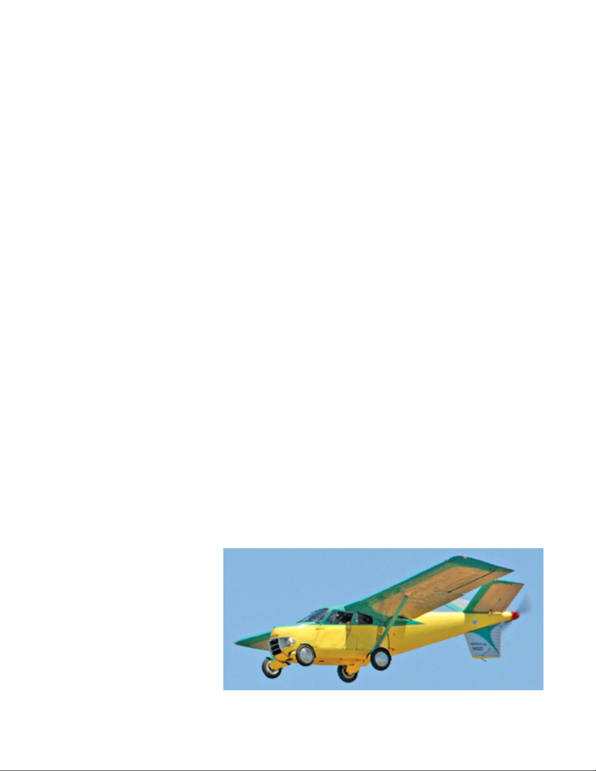
N192D, the onl y still- f lying “Aerocar”.
newspapers and shown in newsreels between features in cinemas,
the public in the U.S. became more
and more air- minded. Accordingly,
articles speculating on the future of
civilian aviation were published in
many magazines and Sunday supplements particularly regarding what
was called, among other things, the
“Everyman Airplane.” In the late
1940s and early 1950s this often took
the shape of a new and then highly
misunderstood type of aircraft, the
helicopter.
In the February 1951 issue of
Popular Mechanics an illustration of
a two- seat, jet- powered helicopter
was shown being pushed back into its
garage by a suburban man in his hat
and overcoat having ostensibly just
own it back from work. An identi-
cal red helicopter is seen above his neighbour’s house. The
article “reported” that anyone could learn to y one of these
machines in only two hours.
Along with this kind of nonsense, fanciful drawings of
boat- aeroplanes and automobile- aeroplanes abounded.
One of these, designed to be a true- functioning automobile as well as a true- functioning aeroplane, “Aerocar”
towed its folded wings and tail section behind whilst on
the road which, when ight was desired, were assembled
and own away. Sounds crazy, does it not? The thing is,
it actually worked. Taylor “Aerocar,” the exception to the
wildly improbable contraptions that had been permeating
the press, was both successfully driven and own in 1949.
Along with so many less practical conceptions, “Aerocar”
was also intended to be the “Everyman Airplane”, however,
only six were built and sold. All six still exist, four of them
are reportedly in yable condition and one, N102D, is still
own.
It was in this chimerical aeronautical atmosphere that
aircraft manufacturers planned to sell (real) aeroplanes to
the public in huge quantities as soon as the war ended.
www.a2asimulations.com ACCU- SIM V35 B BONAN ZA
FOR SIM ULATIO N USE ONLY
:::
A2ASIMULATIONS
7
Page 8

FLYING INTO THE FUTURE
A beautifully res tored Belgianregistered Beech Model 17S
“Staggerwing.” This unique an d
strik ing design is a mass ive and
complicated fabr ic- covere d wood
and steel struc ture powered by a
450 hp Pratt & Whitn ey R- 985 - AN- 1
“Wasp Junior” radial engine . With a
top airspeed of 212 mph (184 knots,
341 km/h,) it was a fast biplane in
the 1930 s, but became less and less
competitive as an executive transport
with the e mergence of the ne w and
more eicient all- metal aviation
technology of the 1940s.
■ Be ech Model 18, he re as
Royal Canadian Air Fo rce
(RCAF ) transpor t. This
aeroplane’s resemblance
to the larger Lockheed
“Elect ra” is likely not
entirely a coincide nce.
■ Be ech AT- 11 “Kans an”
bomber trainer over
Texas in 1943 . One of
49 military variants of
Model 18 , AT- 11 w as the
U. S. Army A ir Force’s
(USAAF) primary bombing
traine r during the war in
which mor e than 40,000
bombardiers were trained.
Modifications included
a transp arent bomber ’s
nose, an internal bo mb
bay and bomb racks and
a dorsal gun turre t for
gunner y training. Photo
from “We stern Trips”
■ The second an d last
protot ype Beechcra
XA- 38 “Gr izzly” shown
here was p roduced with
an operational 75 mm
cannon . It beggars one’s
imagination to think
that the s ame company
which was s till producing
the fabric- covered
“Staggerwing” biplane
also de signed and built
this formidable- looking
and per forming modern
warplane. Photo from “Old
Machine Pr ess”
■ 19 47 Piper J- 3 “Cub.”
The great progenitor
of all general aviati on
light airc ra, what Piper
oered in 1947 was
indistinguishable from the
pre- war “Cub.”
A TWINKLE IN WALTER BEECH’S EYE
By 1945, along with virtually every U. S. manufacturer Beech
Aircraft Company which was founded in Wichita, Kansas in
1932 by Walter Beech, his wife Olive Ann Beech and a few
others began to plan for the coming post- war era. However,
by the late 1930s Beech had designed and produced only
two aeroplane types in any quantity, the 1933 Model 17
“Staggerwing” and the 1937 Model 18, commonly called
“Twin Beech.”
The 1933 Model 17 is called “Staggerwing” because the
upper wing is placed rearward of the lower wing. Model 17’s
airframe is fabric- covered wood and steel, typical of aircraft
of the early- to- mid 1930s, It initially had a xed and later a
retractable undercarriage.
Along with most of the aircraft manufacturers in the
United States in the early 1930s a number of circumstances,
particularly the deadly crash of TWA Flight 599 in which the
beloved Notre Dame University football coach Knute Rockne
was killed,
wave of the future. Not content to merely build a simple
all- metal single- engine light aeroplane Beech jumped into
these new waters with both feet by producing Model 18, a
far heavier and more complex aeroplane than it had ever
built.
Beech’s second aeroplane, Model 18, is an all- metal
twin- engine light transport which, since its introduction in
January 1937 has been a popular and highly successful civil-
ian and military aeroplane. The rst Model 18s were powered by two 330- hp (250- kW) Jacobs L- 6 or by two 350- hp
(260- kW) Wright R- 760E radial engines turning cockpitadjustable- pitch Hamilton Standard propellers. Model
18’s engines were soon upped to 450- hp (336- kW) Pratt &
Whitney R- 985 radial engines turning the new Hamilton
Standard three- blade constant- speed propellers. However,
the construction and manufacturing methods required for
building Model 18 were entirely new to Beech. In fact, Beech
Model 18 was a quantum leap from Model 17 in every way.
1
informed Beech that all- metal aircraft were the
8
A2ASIMULATIONS
:::
ACCU- SIM V3 5B BONA NZA www.a2asimulations.com
FOR SIM ULATIO N USE ONLY
Page 9

Model 17 seats a pilot and three passengers, is a singleengine, fabric- covered biplane with a wingspan of thirtytwo feet weighing 4,250 lbs. fully loaded. By comparison, a
typical late 1930s Model 18 seats two pilots and up to eight
passengers, is a twin- engine, all- metal, cantilever (no
external struts) monoplane with a wingspan of forty- seven
feet, eight inches weighing 7,500 lbs, fully loaded.
After selling only thirty- eight Beech 18s before the United
States’ entry into W.W. II including one to Sweden as an air
ambulance and six to the Nationalist Chinese Government as
M18R Light Bombers, once the war began the various U. S.
armed forces, the Royal Canadian Air Force (RCAF) and the
Royal Air Force (RAF) purchased more than 4,000 Beech 18s.
Beech built two other aeroplanes during the war. One
of these was the twin- engine Beech Model 26 AT- 10/11
“Wichita”/”Kansan,” a militarized derivative of Model 18.
This aeroplane was built in response to the U. S. Army Air
Corps’ (USAAC) requirement for a twin- engine, retractable undercarriage, multi- engine trainer similar to Cessna’s
AT- 8.
The second military aeroplane that Beech designed
and built during the war was the remarkable 1944 Beech
XA- 38 “Grizzly”, an experimental twin- engine ground
attack ghter of which only two prototypes were constructed. “Grizzly” was a completely original design created in response to the USAAF’s requirement for a replace-
ment for the Douglas A- 20 “Havoc” which by 1944 was
long past showing its age “Grizzly” was powered by two
2,300 hp Wright R- 3350- 43 air- cooled radial engines.
Unfortunately these engines were already in use by Boeing
B- 29 Superfortress which had the highest priority for them.
In early 1944 an invasion of Japan was deemed to be likely
and the USAAF wanted a fast, powerful and lethal ground
attack aeroplane which could be employed to neutralize
Japanese fortied ground installations and artillery. For this
purpose Beech designed XA- 38 around the most powerful
engines available (or unavailable as it turned out) installing a 75 mm cannon in its nose as the aeroplane’s primary
weapon in the same fashion as North American B- 25G/H
“Mitchell.” “Grizzly” also had two remotely operated
machine gun turrets similar to those in B- 17, P- 61, B- 29,
Me- 210 and He- 177A. With a total 4,600 hp, it had a blister-
ing top speed of 370 mph at sea level, faster than most of the
Japanese ghters that it was likely to encounter. Although
the war ended before XA- 38 “Grizzly” could go into production and prove its worth in combat, it was, in its day,
an extraordinary and unmatched achievement in design and
sophisticated construction technique for what had previously been a light aeroplane company. Beech’s production
of both Model 18 and “Grizzly” set the stage for another
aeronautical achievement still to come.
The extraordinarily prolic Beech Model 18 “Twin Beech”
was produced in 25 USAAF variants, 14 U. S. Navy (USN)/U.
S. Marine Corps (USMC) variants and 9 RAF and RCAF variants as well as being in operation in 43 foreign air forces.
But for this versatile and excellently performing modern
aircraft Beech might have continued to produce only its
■ 19 46 Taylorcr a BC- 1 2D. C. G. Taylor’s clean design made BC-
12DA a slight refine ment of his 1938 Model “BC,” whic h was itself
a refinement of the 1938 Piper J- 3 “Cub.” BC- 12 has dua l control
wheel s instead of control columns and a d oor on each side of the
cabin for easy entr ance and exit. Whilst Taylorcr a’s side- by- si de
seating is better for instr uction as well as for pilot- passenger
communic ation in general, these a eroplanes are not very wi de and
their snug interiors are insuicient for two “full- sized” adults.
■ 19 47 Stinson 108- 2 “Station Wagon.” A roomy four- seater,
interio r wood panels and a r einforced floor permit 6 00lb (272kg)
of bagga ge to be carried in t he passenger compartment. It s 165
hp Franklin 6A4- 165- B3 engine ca n use automotive fuel with th e
installation of a converter k it. The Stinson’s wings’ fixed leadingedge slat s make the 108 seri es excellent and re liable slow flier s,
enabling them to easily get into and o ut of small tree- lined fields.
■ 19 47 Aeronca “Champ.” Another ref inement of the J - 3 “Cub”
design with similar t andem seating an d similar perfo rmance. Solo
from the f ront seat is a definite improvement over “C ub’s” rear
seat solo station a nd “Champ’s” large wind ows make visibilit y
in all directions much better. Having had a number of hour s in
a “Champ,” this wr iter has found this respons ive and sprightl y
aeroplane to be the b est of the lot of this t ype.
■ 19 47 Luscombe 8A “Sil vaire” on float s. Rather fast f or its 65 hp
engine wi th a top airspeed of 85 mph or so, the aerop lane in the
photo is identical to t he “Silvaire” in which this writer firs t received
instr uction and lear ned to fly the age of 1 2. Luscombe “Silvaire”
has dual control sticks rath er than control wheels making it a ver y
fun and responsive aeroplane.
www.a2asimulations.com ACCU- SIM V35 B BONAN ZA
FOR SIM ULATIO N USE ONLY
:::
A2ASIMULATIONS
9
Page 10

FLYING INTO THE FUTURE
■ Ryan (originally Nor th American L- 145 ) Navion B Super 26 0 C-
FCTI. It i s not merely a coincidence that airfra me of this excellent
four- seat aeroplane is reminiscent of P- 51 “Mus tang” upon
which it s design was base d. Introduced in 1948, the retra ctable
tricycle undercarriage Navion is powerful and fast . 260 hp
Navion variants have a useful load of 920 lbs, a top airspeed of
175 mph, can car ry four pass engers in comfor t over a range of
595 miles , take- o in 400 feet and la nd in 466 feet. Navion was
Bonanz a’s closes t rival in the late 19 40’s and during th e 1950s,
outperforming Bonanz a in many ways. Celeb rities Veronic a
Lake, Ar thur Godfrey, Mickey Roone y and Bill Cullen were among
those wh o owned and flew Navions. Many are still f lying and
whilst oering something of an awkward climb to ente r they are
conside red to be a great barg ain on the used aer oplane market.
Photo by Barry Gr iiths.
■ Piper Pa- 2 2 “Tri- Pacer.” Introduced in February 1951, this
comfor table four- s eat aeroplane is e ssentially a Pip er PA- 20
“Pacer ” with a nose wheel . Although rather a throwb ack with
its fab ric- cover ed aluminium fram e and stodgy app earance
(derisively nicknamed “Fly ing Milk Stool,”) 160 hp ver sions of
this fine aeroplane give it us eful load of 890 lbs, a top airs peed of
141 mph, an 800 fpm climb rate and a range of 650 miles, all with
four 170 lb passengers on board. This writer ha s enjoyed many
pleasant hours f lying Tri- Pacers as well a s its two- seat version,
PA- 22- 108 “Colt .” Tri- Pacer was introduced six years ahea d
of its chi ef tricycle- undercarriage riv al, the all- metal Cessna
172. As good as Tri- Pacer was and is, it has neve r been serious
competition for Bonanza. A John Marco photograph
fabric- covered “Staggerwing” bi- plane as it had before
the war. As it was, Beech produced 16 variants of Model 17
“Staggerwing” for the USAAF, the USN/USMC and for fteen
foreign air forces. However, it was Beech’s mass production
of the sophisticated Model 18 “Twin Beech” which considerably informed the company regarding modern metal construction methods and gave it otherwise unobtainable and
invaluable experience regarding the construction and production of complex all- metal aircraft. This precious experience gave Beech a great advantage over virtually all of the
other U. S. light aircraft manufacturers when it conceived
and designed Model 35 “Bonanza” in 1944.
Whilst Model 18 was a great success, the production of
which continued until 1970 with more than 9,000 ultimately
produced, Walter Beech and his sta had been optimistically looking toward the post- war civilian aviation world
to come. The plan they developed was to produce a highperformance, luxury, all- metal, four seat, single- engine
light executive aeroplane that would be relatively simple
and ecient to operate.
Except for Cessna’s AT- 8/AT- 17/UC- 78/JRC “Bobcat”/
“Crane” primarily wooden “Bamboo Bomber” bomber
trainers during the war, the other light aeroplane manu-
facturers primarily produced only slightly modied military
versions of what they had been producing before, i.e., light,
low- powered, two- seat, “low and slow” fabric- covered
aeroplanes.
Piper produced O- 59/L- 4, the military version of its
“Cub” and few glider trainers. Stinson produced a military
version of its 105 “Voyager’ designated L- 5 “Sentinel,” a
military version of its pre- war SR- 10 “Reliant,” designated
UC- 81, as well as Model 74/L- 1 “Vigilant,” a larger, more
powerful light observation aeroplane. Aeronca produced a
military version of its tandem- seat trainer, “Champ.” des-
ignated O- 58/L- 3 “Defender” and like Piper, a number of
glider trainers. Taylorcraft produce a military version of its
Model D, designated O- 57/L- 2.
After the war these manufacturers made few if any modi-
cations to their aeroplanes and those which simply were
essentially their early 1940s designs were put back onto
the market. Photographs on Page 9 show some of Beech’s
“competition” were oering in the post- war, late 1940s:
Of course, more powerful and sophisticated aeroplanes
such as Cessna 190/195 (see further discussion of this aero-
plane below,) Ryan Navion, Piper Tri- Pacer, Cessna 172
and Bellanca 14- 19 would soon be produced; however, until
Piper’s 1958 PA- 24 “Comanche 250,” nothing came close
to ousting Bonanza from its position at the top of the heap.
“I SEE A NEW SUN UP IN A NEW SKY”2
It is an oft- told tale that by the end of W.W. II, U. S. light
aeroplane manufacturers, all of whom had been forced to
curtail their usual retail businesses during the war to supply
aircraft for the armed services, looked forward with anxious
hearts and open coers to the soon- to- come peace during
which they hoped and believed that the tens of thousands
of returning military pilots, having experienced the “joy”
of ight, would wish to continue the same and would gladly
purchase low- priced, simple aeroplanes by the bushel- full.
The Serviceman’s Readjustment Act of 1944, popularly
3
10
A2ASIMULATIONS
:::
ACCU- SIM V3 5B BONA NZA www.a2asimulations.com
FOR SIM ULATIO N USE ONLY
Page 11

known as the “G. I. Bill,” designed and largely drafted by
the American Legion and the Veterans of Foreign Wars, was
a Federal entitlement program which provided a range of
nancial benets, including free ight instruction all the
way to an Airline Transport Rating, for returning WWII veterans. Aircraft manufacturers were all quite aware of this
and they saw it as a boost to what they believed would be a
glorious new, commercially lucrative general aviation boom.
The aeroplanes that they had been producing before being
interrupted by the war - Piper J- 3 “Cubs”, Taylorcrafts.
Stinsons and the like would be just perfect, or so they
thought. What was not spoken of if it was thought of at all
was that immediately after the end of the war a tremendous
glut of surplus “grasshoppers” (all of those high- wing, low
powered, mostly two- seat aircraft) would be oered as surplus to the public at very low prices. For instance, in 1945
the Oce of Price Administration (OPA) made surplus twoseat Aeronca L- 3B “Champs” in virtually unused condition
available for $1,788.00 ($19,963.94 in 2018 at a cumulative
rate of ination of 1,016.6%) and four- seat Stinson UC- 81/
AT- 19 “Reliants” available for $6,736.00 ($75,210.91 in
2018 at the same rate of ination.)
However, Walter Beech and his sta had a completely
dierent view of what Beech’s role would ideally be in the
post- war future. Their experience with light aircraft had
solely been with Model 17 “Staggerwing”, a fairly large and
expensive executive aeroplane. Beech’s plan was that its
new post- war aeroplane would well- t this role.
In 1945 and for a decade and a half thereafter, the now-
familiar culture of the casual weekend pilot who usually ies
locally in good weather with friends and family to sightsee and perchance to purchase a few of those $100 dollar
hamburgers at a far- o little airport’s snack bar, the vast
majority of whom have little ight time and are not instru-
ment (IFR) rated, did not yet exist. Accordingly, once plans
for what became Bonanza began to develop, an important
aspect of this aeroplane’s design was that it did not include
compromises which would make it especially forgiving or
gentle- ying, particularly not at the expense of performance. Thus, Bonanza was not intended to cater to the
aforementioned not- yet- existent culture of casual pilots.
Rather, it was designed to be a business tool, an executive
transport aeroplane which would be owned by success-
ful businesses and own by professional pilots who would
transport those executives who required quick, private and
convenient transportation to places that were too distant or
inconvenient for ecient ground travel. Oh yes, and lest we
forget, Bonanza was also intended to be an exclusive, con-
spicuous totem of nancial accomplishment.
Since its introduction in 1936, and into the early 1940s,
Walter Beech and Co. had been well and painfully aware of
their greatest competitor in the corporate aviation genre:
Spartan Aircraft Company’s 7W “Executive.” This highly
advanced aeroplane is a sleek and muscular- looking, allmetal, retractable undercarriage, low- wing monoplane
which exhibited spectacular performance for its time, with
a top airspeed of 257 mph (223 knots, 414 km/h) whilst
■ 19 49 Bellanca 14- 19 “Cruis emaster.” An upgrade of the pre - war
Bellanca 14- 7 an d the post- w ar Bellanca 14- 13, 14- 19 has a large,
comfor table cabin for four and is powered by a Fran klin 6A4- 335- B3
190 hp engine. “Cruisemaster’s” triple tail and its wooden wing
garnered it the nickname “Cardboard Constellation” aer Lockheed’s
“Constellation.” However, like Lockheed’s triple- tail marvel,
“Cruise master’s” per formance was in many ways bet ter than its similar
contemporarie s, including Bonanza, with a u seful load of 1,02 5 lbs,
a top airspeed of 174 mph, a rate of climb of 1,2 50 fpm and a fullyloaded r ange of 435 miles. A t ailwheel aeroplane with r etractable main
underc arriage in the new t ricycle under carriage world, its ret ro wood
and fabr ic construc tion and undeniab ly quirky appearance did not aid
its over all public accept ance. Whilst in 19 59 14- 1 9 would be converted
to a retra ctable tric ycle undercarriage by “Dow ner Aircra” (B ellanca’s
new name, ) only around 600 of the original 14- 19 “Cruisem asters” were
produce d. Whilst in many ways “Cruisemaster ” is a better- perfor ming
aeroplane, Bonanza remained unchallenged.
■ Cessna 172. Introduced in 1 956, it was the direct competitor of Pip er
Tri- P acer. All metal and looking far more moder n than Tri- Pacer, C- 172
is a Cessna 170 with a nose wheel. Despite its sleek appe arance, C- 172
does not p erform as well as Tri- Pacer in many areas. 160 hp ver sions
of C- 172 give it a useful loa d of only 758 lbs, a top airspeed of 140 mph,
a rate of climb of 721 fpm an d a possible range of 696 miles , but with
only two rather slim passengers on board. Ces sna 172 might have wellcompete d with Tri- Pace r but it, too, was no competiti on for Bonanza.
www.a2asimulations.com ACCU- SIM V35 B BONAN ZA
FOR SIM ULATIO N USE ONLY
:::
A2ASIMULATIONS
11
Page 12

FLYING INTO THE FUTURE
Spartan 7W “E xecutive.” The name says it all.
Sleek, modern, powerful and sensual, this was
top shelf, first- class personal transportation for
the supe r- r ich corporate executive in the mid
1930s an d early 1940s. Photo fro m Flickr.
Restor ed Spartan 7 W
“Execu tive” previously owned by
Texaco, Inc. in t he late 1930s.
comfortably carrying up to four with a range of 1,000 miles.
Spartan “Executive” boasted such notable owners as industrialist and lm mogul Howard Hughes, oil magnate, nancial wizard and overall S. O. B., J. Paul Getty, and no less
than His Royal Highness, King Ghazi of Iraq. To Beech’s
chagrin, from its rst appearance Spartan “Executive” was
universally considered to be the “Rolls- Royce” of pre- war
executive aeroplanes which even Walter Beech would have
had to reluctantly admit, deservedly so.
Compared to the potent and swift- looking Spartan 7W
“Executive,” Beech’s contemporary Model 17’s top speed
is 45 mph slower and its range of 670 miles is 330 miles
less. Walter Beech had to admit, at least inwardly, that his
Model 17, while an excellent aeroplane in its own right, was
clearly and eminently inferior to Spartan 7W. To make matters even worse for Beech, both Model 17 and Spartan 7W
were powered by the same Pratt & Whitney R- 985- AN- 1
“Wasp Junior” radial engine producing 450 hp (340 kW) at
2,300 rpm.
Whilst Model 17 was attractive to the military in small
batches during the war and each of fourteen foreign nations
operated a scant few of them, Model 17 never arose to the
level of a truly mass- produced aeroplane with a total of
only 785 examples having been produced from 1933 to 1949.
Spartan 7W was in production for only ve years (1936 to
1940) and only 34 examples were produced; however, 7W’s
spectacular, striking appearance and blazing performance
epitomised the value of the practical application of advanced
aerodynamics, modern construction methods and materials
and the latest concepts in aeronautical structural engineering in the arena of executive aircraft. While no- doubt painful, this lesson was not lost on Walter Beech, who would
soon put it to good use.
To be fair, Model 17 “Staggerwing” is a unique and extraordinary design particularly for a biplane, and it is certainly
impressive to the eye (many consider “Staggerwing” to be
the most beautiful biplane ever built.) Despite its inherent
disabilities, the extra wing along with the struts and wires
required to keep it in place, “Staggerwing” performed very
well indeed. However, aside from its inferior overall performance compared to Spartan 7W whilst powered by the same
engine, “Staggerwing” was also very costly to build and
delicate to maintain. Its old- school wood and steel- tube
construction with thousands of intricate structural parts
and connectors covered by stitched and doped fabric, the
entirety of which must be meticulously assembled by many
skilled hands, was highly labour- intensive (i.e., expensive)
to construct. Additionally, “Staggerwing” and all fabriccovered aeroplanes’ owners always have a terrible “Sword
of Damocles” hanging over them in the form of an inevitable and expensive re- covering and paint job awaiting them
in the future. Altogether, it is no wonder that by mid- war
Beech was beginning to have serious thoughts about a more
modern, more ecient and less complicated replacement
for Model 17.
Walter Beech, a man of a considerably forceful personality was, to his credit, not at all hidebound to the past or
by traditional methods of building aeroplanes. Additionally,
he was determined that his “star” aeroplane would never
again be so outperformed as had been Model 17. In January
1945, with the war still raging all around the world but with
imminent peace and a bright, shimmering future clearly
in sight, Beech, unlike virtually every other light general
aviation aeroplane manufacturer, began to draw plans for
something entirely new that would be an icon for and of
that bright future.
12
A2ASIMULATIONS
:::
ACCU- SIM V3 5B BONA NZA www.a2asimulations.com
FOR SIM ULATIO N USE ONLY
Page 13

Rolled ou t of the factor y on 9 September 1940, this was the last Spar tan 7W, later calle d
“Mrs. Mennen.” It was originally purchased by Texaco, Inc. (now a subsidia ry of Chevron
Corporation) for corporate use in the New York State/N ew England area. This magnificent
aeroplane cost $26 ,200.40 in 19 40 ($467,029.62 in 2018 at a cumulati ve rate of inflatio n of
1,682.5%) and was o ne of five Spartan 7Ws owned by Texaco, who based this aircra at
Roosevelt Field lo cated in Mineola (now Garden City), New York.
This aeroplane was p urchased by Geo rge
Mennen of the Menne n Company, Morris town,
New Jersey in the sp ring of 1969. It was then
painted “M ennen Green” and named “Mrs.
Mennen .” “Mrs. Mennen” was so ld, traded and
bought by m any dierent owne rs over the
years unt il it was purchase d in October 200 4 by
Will Mennen, George Mennen’s grandson.
“A BUILT- IN TAILWIND”
Walter Beech wanted his new aeroplane to set the standard
for quality and performance. It was to be something not yet
seen, something that one might to y into the future.
He told his design sta to come up with something not
merely of 1945, but of 1955 and 1965 - and beyond. It had
to be a sleek, clean design, all- metal, simple (inexpensive)
to build, look sexy, go fast, carry four in comfort and have
a range of around 700 miles. These factors were imperative
if Beech was going to lead the post- war pack and attract
wealthy corporate customers.
It is well to recall that in 1945, as Walter Beech and his
team’s ideas for a new light aeroplane were accumulating, the current stars of aviation were all- metal, single-
engine, retractable undercarriage piston- engine ghters – Mustangs, Corsairs, Spitres, etc. These powerful,
sleek aeroplanes appeared fast even when sitting still and
they made the blood rush and the imagination soar just to
look upon them. Beech was determined that his new aero-
plane would be just like that. He wanted to build a high-
performance, light executive transport aeroplane with, as he
put it, “a built- in tailwind.”
At Walter Beech’s behest, Ted Wells, Beech’s VicePresident of Engineering who had been instrumental in
the design of both the Model 17 “Staggerwing” and Model
18 “Twin Beech,” together with project engineer Ralph
Harman, set about the task of putting together a team of
creative aircraft designers. Their mission was to design an
entirely new single- engine aeroplane not only for the postwar era, but for decades to come. Such an aeroplane had also
been Harman’s dream and he was highly delighted to have
the opportunity to be able to make it a reality.
It is reported that Beech’s employees and company ocers
were extremely optimistic about Beech’s future given its
wartime experiences building powerful and sophisticated
all- metal aeroplanes. They rightly felt that they had a signicant “leg- up” on their competition and they were anxious and ready to prove what they could do.
The design of what was to become “Bonanza” was very
much a team eort. Ralph Harmon was the overall Project
Engineer, also taking on responsibility for the design of the
interior and undercarriage. Jerry Gordon, Beech’s Chief of
Aerodynamics, created the shape of the wing and tail surfaces. Wilson Erhart designed the interior structure of the
wings. Alex Oderse designed the fuselage. Noel Naideno
designed the fuel system and engine compartment. It is
a great compliment to the skills of these engineers that
Bonanza ultimately appeared to be the conception of a
single brilliant individual rather than the product of a committee that it was.
No doubt greatly inuenced by Beech’s past success with
Model 17 as well as the success of rival Spartan Corporation,
Walter Beech decided from the outset not to include a trainer
or low- cost cruiser in Beech’s post- war menu.
4
That eld,
it was thought, would soon be overlled with “Cubs”,
“Champs” and the like. No, Beech’s new aeroplane was to
be aimed solely at the highest end of the light general aviation aeroplane market. It was to be more than a means of
transportation; it was to be an objet de prestige like a Rolex or
a Rolls- Royce, something literally exclusive which only the
wealthiest could aord to obtain, the possession of which
would openly attest to the owner’s prosperity, sophistication and good taste.
As mentioned, Walter Beech was known to be a very for-
ward character in both his conceptions and his mode of
expression. Who else but such a very condent “Type A”
www.a2asimulations.com ACCU- SIM V35 B BONAN ZA
FOR SIM ULATIO N USE ONLY
:::
A2ASIMULATIONS
13
Page 14

FLYING INTO THE FUTURE
individual would plan for his company to enter a new and
unknown aviation market with the most advanced and
expensive aeroplane of the lot? Whilst Beechcraft would
eventually see the ecacy of producing less sophisticated
and less expensive aircraft (see endnote 4,) this rst postwar Beech was intended to come out of the box rmly sitting atop of the aviation mountain, condently and reso-
lutely daring all comers to topple it. As history has shown,
despite a most valiant but ultimately failed eort by Piper
to do just that with its superb PA- 24 “Comanche,” no aeroplane, so far, has quite been able to do so.
WHY “BONANZA”?5
In Walter Beech’s own words in 1946, “Airplanes have been
named after stars, galaxies, constellations, animals, sh,
birds, and natural phenomena such as hurricanes, lightning
and thunderbolts. For our new Model 35, Beech Aircraft has
sought to nd a name that would be descriptive of the extra
value oered in the way of economy, performance, and
pleasure to the owner. We examined the word ‘Bonanza’,
which in English has a common meaning of a rich source of
prot or gain or an unusual value.”
Whilst there is no evidence to the contrary that Mr. Beech
sincerely intended that owners of his new aeroplane would
feel that they had indeed purchased a “bonanza”, I think that
we may be forgiven if we strongly suspect that he sincerely
intended that his new aeroplane would be a “bonanza” for
Beech Aircraft as well – and so it has been on both counts.
Additionally, Mr. Beech said, “We found that it (‘bonanza’)
... also has an additional meaning of ‘fair weather’ in certain foreign languages.”
In Spanish and Portuguese, “bonanza” means prosperity,
success and fair weather;
In French, “bonance” means calm, tranquil and smooth
seas.
In Italian, “bonaccia” means prosperity, calmness and
tranquillity.
elevator at its trailing edge, often split into left and right
horizontal stabilizer/elevator units acting in unison, one on
each side of the rearmost end of the fuselage. Accordingly,
the position of the rudder aects the yaw axis and is controlled by the pilot by pushing the left (left yaw) or right
(right yaw) rudder pedals in the cockpit. The position of the
elevator aects the pitch axis and is controlled by the pilot
by either pushing (nose down) or pulling (nose up) a control
stick or a yoke. Conventional rudder and elevator control
surfaces are completely independent of each other.
On a “V”- tailed aeroplane, however, the rudder and elevator are not separate and independent control surfaces.
Instead, the moveable control surfaces at the trailing edge
of the two tail surfaces, the ruddevators, act just as the
name indicates, each one controlling both the yaw and pitch
axes simultaneously. A fairly complex system of rigging the
ruddervators permits a pilot to y a “V”- tailed aeroplane
exactly as he or she ies a conventional- tailed aeroplane
using normal rudder pedals and control stick/yoke inputs.
Note: What follows is a description of the operation of an
aeroplane’s movable control surfaces where these surfaces
are located at the rear of the aeroplane and does not apply
to aircraft with elevators ahead of the wing (canard) or aircraft equipped with elevons or ailevators (elevator and aileron operating in a single control surface as found on many
“Delta” winged aircraft).
ELEVATOR/PITCH CONTROL
The following drawings show the control surface movements and tail forces for “V”- tailed aircraft when the stick/
yoke and rudder pedals are operated as viewed from the rear.
As shown, because the control surfaces are oset from
horizontal and vertical, the forces created when the rudder-
vators are displaced are similarly oset.
THE “V”
During WWII, as aeronautical engineers in Great Britain and
the United States began to think about how the airspeed of
currently operational aircraft might be increased, the idea
of using a “V”- tail as a replacement for a conventional tail
arrangement was raised. “V’- tail was not, however, a new
concept at that time.
The rst “V” or “Buttery” tail surface arrangement (an
aircraft tail- surface conguration combining rudders and
elevators into two, single control surfaces called “ruddervators” was invented and patented in 1930 (Patent Polksi #
115938) by Polish pilot and aeronautical/aerospace engineer
Jerzy Rudlicki (14 March 1893 – 18 August 1977.)
(For the purpose of this discussion, the term “ruddervator” will refer to each separate “V” surface as well as to
the hinged, movable control surfaces at their trailing edges)
A conventional- tailed aeroplane has one or more vertical
ns with a hinged, movable rudder(s) at its (their) trailing edge and a horizontal stabilizer with a hinged movable
14
A2ASIMULATIONS
:::
ACCU- SIM V3 5B BONA NZA www.a2asimulations.com
FOR SIM ULATIO N USE ONLY
Page 15

1. When the yoke is pushed
forward to lower the nose, the
ruddervators move downward
as does a conventional elevator
control surface. However, they
also necessarily create additional
forces which push and pull to
each side (yaw axis) as well.
Each ruddervator osets the
other’s yaw force, but because
of the dual direction of forces
created by ruddevators, they are
functionally less aerodynami-
cally ecient than a similarly
sized and displaced horizontal control surface. Accordingly,
rudddervators must be larger
and/or be displaced farther than
a conventional horizontal elevator surface to create an equal
force in the pitch axis.
“V”- tail mixing linkage: The blue section shown is the fuselage’s
rearmo st end looking up from under neath. There are t wo rods
exten ding o to the le of this photogra ph that connect to t he
actual rudder vators. Rightward motion of the top rod (due to
either r ightward motion of the ent ire mixer assembly due to a
pitch command, or cloc kwise rotation of the ass embly due to
a yaw comman d) will deflect the rudd ervator one directio n;
lewa rd motion will def lect it the othe r direction. This is the sam e
for the other rudd ervator similarly conne cted past the b ottom of
the photo graph. Simple, eh?
2. When the yoke is pulled
rearward to raise the nose, the
ruddervators move upward as
does a conventional elevator control surface. However, they
also create additional forces which push and pull to each
side as well, as described above. The ineciency caused
by the oset forces is similar to when the ruddervators are
pushed downward.
3. When the right rudder pedal is pushed to yaw the nose
to the right the ruddevators both move to the right. In order
for the left ruddervator to move to the right it must also
move upward creating an additional nose up force, and
when the right ruddervator moves to the right it must also
move downward creating an additional downward pitch
force. The ruddervators’ up and down pitch forces cancel
each other out so that only a right yawing force is created.
The canceled- out upward and downward forces create inef-
ciency as stated above.
4. When the left rudder pedal is pushed to yaw the nose
to the left, the ruddevators both move to the left. In order
for the left ruddervator to move to the left it must also move
downward creating an additional nose down force, and
when the right ruddervator moves to the left it must also
move upward creating an additional nose up force. Each of
the ruddervators’ up and downward pitch forces cancel each
other out so that only a left yawing force is created. The
canceled- out upward and downward forces create ineciency as stated above.
5. When both the yoke and either rudder pedal are moved a
combination of the above control surface movements is created so that the nose may be raised or lowered while simultaneously yawing the nose to the left or right as desired.
As you may imagine, the linkages required to move the
ruddervators to comply with the exact forces which a pilot
may require are quite complicated.
On a “V”- tail Bonanza, with full up elevator and with no
rudder input, the left ruddervator is displaced 22½º upward.
With full right rudder and with
the elevator neutral, the left
ruddervator is displaced 23º
upward, and with full up elevator and with right rudder simultaneously, the left ruddervator is
displaced 44º upward. By contrast, the elevator of the con-
ventional tail of an A36 Bonanza
is limited to 23º upward and 20º
downward displacement, while
the rudder is limited to 25º left
or right displacement.
“V”- TAIL DISADVANTAGES:
■ Weight
While Bonanza’s “V”- tail is legendary, the myriad aeronautical
claims that Beech has perennially made for it do not entirely
or even partially live up to that
legend. Bonanza’s “V”- tail is
not lighter than a conventional tail arrangement as the two
ruddervators must each be larger than any of the three conventional tail surfaces. Because the control force of the two
ruddervators must equal the control force of the conventional three- surface design, the two ruddervators, in sum,
must have approximately equal or greater area because of
“V”- tail’s aerodynamic ineciencies when compared to a
conventional tail. Additionally, the complex control linkage
of the “V”- tail arrangement is heavier than the far simpler
conventional- tail linkage and is located at the most rear-
ward position. For example, a 1968 E33A Debonair, which is
virtually identical to a similarly equipped 1968 V35A “V”-
tail Bonanza except for the tail surfaces, is 45 lbs lighter
than V35A. However, this is not the total story of the disadvantages of the “V.”
■ Greater interference drag
NACA wind- tunnel studies of the generic “V”- tail design
have found that a small amount of interference drag is
reduced by the reduction of one intersection of tail surfaces
(two instead of three.) However, what small advantage may
be gained thereby is virtually eliminated by the increase of
interference drag created at the proximate inside surfaces of
the “V” surfaces where they are attached to the aft fuselage.
Interference drag caused by the proximity of the inside base
of each “V” surface occurs in this manner: Air molecules
moving past the lower inside surfaces of the ruddervators
become commingled and disorganized creating a disturbed
airow which creates interference drag.
■ Greater induced drag
In order to ensure pitch stability, the aft pitch controlling
surfaces of any aeroplane must be set at such a positive
www.a2asimulations.com ACCU- SIM V35 B BONAN ZA
FOR SIM ULATIO N USE ONLY
:::
A2ASIMULATIONS
15
Page 16

FLYING INTO THE FUTURE
(nose up) incidence when the elevator is neutral that suf-
cient “decalage” (also known as “horizontal dihedral”) is
created relative to the wing’s angle of incidence. The non-
horizontal ruddervators, when at neutral, are less ecient
in creating sucient decalage than a conventional horizon-
tal stabilizer/elevator and therefore must be set at a greater
positive incidence. Being at greater incidence puts each of
the ruddervators under a greater positive aerodynamic load
at all times and thereby creates greater induced drag (drag
which occurs whenever an aeroplane’s wing and/or tail surfaces positively redirect the oncoming airow) than are created by conventional horizontal surfaces.
Additionally, in Bonanza, the right ruddervator is oset a
few degrees more to the right than the left ruddervator to
counter P- factor, also called “asymmetric blade eect” and
“asymmetric disc eect” (relocation of a spinning propel-
ler’s centre of thrust when the propeller disc is at a positive
angle of attack [Alpha] which in a right hand- turning propeller exerts a left yawing moment on the aircraft and vice
versa). To reiterate, because each ruddervator is oset from
vertical, they must be set at a greater degree to the right to
counter P- eect than a conventional single n/rudder surface would need to be to exert the same force.
■ Form/pressure drag
In order to preserve pitch and yaw stability as well as to
grant ecient control displacement forces, the wetted area
(the area exposed to the oncoming air) of the ruddervators
must be roughly equal to that of conventional tail surfaces.
Accordingly, each of the “V” surfaces must be larger both
in chord and/or span than that of equally- eective conventional tail surfaces. Accordingly, the ruddervators’ wetted
area produces form/pressure drag equal to or greater than
that produced by conventional tail surfaces.
■ Yaw/Roll Instability or “Dutch Roll”
Properly applied, a small amount of dihedral creates a stabilising force in a wing or horizontal tail surface so that when
it is displaced in the roll axis by turbulence, a gust of wind
or after the aircraft is deliberately banked, it will tend to
return to level ight. However, when tail surfaces are radically oset upward (as in a “V”- tail,) a very strong dihedral
force is created at the rear of the aeroplane.
Some aircraft are designed with some amount of horizon-
tal tail surface dihedral to increase roll- axis stability. Less
commonly, some aircraft are designed with some negative
(downward) horizontal tail surface dihedral, called “anhedral” or “cathedral,” to decrease what is considered to be an
excess of roll- axis stability. It is understood that extreme
dihedral (or extreme sweepback) tends to instigate a condition called “Dutch Roll,” a series of out- of- phase turns
in which an aeroplane tends to roll from side to side whilst
also yawing in the opposite direction of the roll and not
remaining at or returning to level ight without engaging
a yaw and/or pitch damper, an auto pilot and/or the pilot’s
corrective control input.
Accordingly, Bonanza’s 30º- 33º ruddervators tend to
cause Dutch Roll at the rear of the aeroplane, which has
been reported to cause both yaw and pitch “wandering” and
pitch “seeking” at cruise airspeeds.
ADVANTAGES:
■ Airspeed?
Beech’s claim that a “V”- tail design suciently reduces
drag so that it increases the aircraft’s airspeed as compared to the same aircraft with a conventional tail has been
shown not to be so. If any such advantage exists at all, it is
de minimus at best. Even Beech (which some have claimed
has not always been known to have played entirely fairly
with regard to its aeroplanes’ published airspeed specications) lists the cruising airspeeds of the last “V”- tail
Bonanza, V35B, as being the same (172 knots) as an equally
powered F33A (a conventionally- tailed Bonanza.)
■ Appearance
Many would agree that the undisputed advantage that a
“V”- tail has over a conventional tail is its appearance. It is
certainly eye- catching and unless the truth of the matter is
known to the observer, a “V”- tail appears to be cleaner and
more ecient. Beechcraft apparently heavily relied upon
this erroneous assumption and armatively added to it for
decades in order to generate Bonanza sales. As stated before,
despite its exotic appearance and appeal, the “V”- tail actually does not improve aircraft performance in any measurable amount as compared to a conventional tail.
A RARELY ADOPTED TAIL DESIGN
There are so many ineciencies and control rigging complications involved with the “V”- tail design that it is not a
surprise that it has been so rarely used.
Whilst at least 15 jet engine- powered military aeroplanes and at least one helicopter incorporating a “V”- tail
are known to exist at this time (2018,) the only piston-
engine ghter known to have been built with a “V”- tail is
the experimental Bell P- 63A- 8 “Kingcobra”. This one- o
aeroplane was a test bed to nd out if such a tail congu-
ration might increase the top airspeed of the already quite
fast P- 63D “Kingcobra”. Powered by an Allison V- 1710- 109
engine producing 1,425 hp and with a top airspeed of 437
mph at 30,000 feet (on par with P- 51 “Mustang’ and P- 47
“Thunderbolt”), P- 63A- 8 was already ying nearly as fast
as a propeller- driven ghter could be made to y. This
P- 63D was so modied and was designated P- 63A- 8. It
broke up during diving tests before it could be determined
whether the substitution of the “V”- tail produced less drag
than the conventional tail surface arrangement and accordingly produced any increase of airspeed. It is not reported
whether the “V”- tail was the cause of P- 63A- 8’s in- ight
breakup but speculation thereof abounds. Experiments with
“V”- tails were not made thereafter.
In 1944 Beech built an interesting experimental Model 18
“Twin Beech” designated A- 19 on the airframe of a USAAF
A- 10 “Wichita.” A large “V”- tail was substituted for the
conventional tail surfaces. Extensive stability and control
16
A2ASIMULATIONS
:::
ACCU- SIM V3 5B BONA NZA www.a2asimulations.com
FOR SIM ULATIO N USE ONLY
Page 17
1944 Beech built a one- o A- 19, wh ich was a USAAF A- 10 “Wichita” with an exper imental “V”- tail . A- 19 was the first and la rgest Beech aircra to
that date with such. At the time, many might have won dered why Beec h was experime nting with a “V”- tail . Time would soon s olve that myster y.
A- 19 would cert ainly be a challenging subjec t for a “can you name this aeroplane” contest. USA AF archive photo, circa 194 4.
■ 19 48 Beech Mod el 34
“Twin- Quad”
■ Bell P- 63A- 8 (also
designated RP- 6 3G). This oneo experimental aeropla ne
was base d upon the basic
airfr ame and engine of P- 63D
“Kingcob ra” which usually ha s
a bubble canopy in place of
P- 39 “Airacobra’s” automotivestyle doors. However, P- 63A- 8
retained the old- style doo rs,
possib ly to ensure a safer
emergency in- flight exit.
■ Eclipse Aviati on 400. If you’re going to put a single
jet engine on top of the f uselage a “V”- tail s eems like
your bes t, if not your only be t.
■ Rob in ATL Beyond a ppearance, the re seems to
be no real need for a “ V”- tail in this design . As can
be seen , the rudder vators are so large that they
are surel y as heavy and pro duce as much drag as a
conventional cruciform tail.
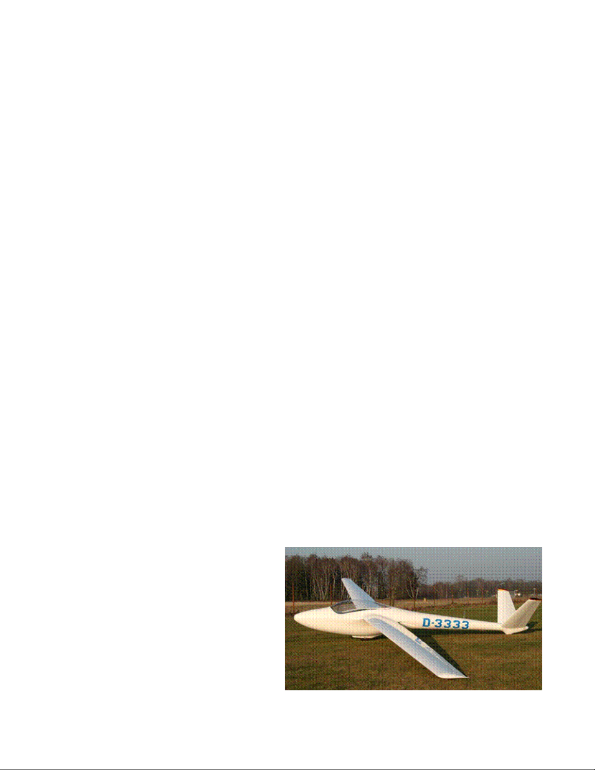
■ H- 101 Salto aerobatic sailpl ane. Here, the “V”- tail
makes some sense. Without t he need to oset a
spinning propeller’s P- Factor, the ruddervators can
be smalle r (as they clearly are in this design) than
on a propeller- driven aircra, and accordingly may,
in fact , be lighter and les s drag- producing th an a
conventi onal tail would be.
www.a2asimulations.com ACCU- SIM V35 B BONAN ZA
FOR SIM ULATIO N USE ONLY
:::
A2ASIMULATIONS
17
Page 18

FLYING INTO THE FUTURE
1947 Beech Model 35 Bonanz a prototype version 4
of the 5 Bonanza air frames which Beech built and
tested . Version 4 was submitted to ob tain Model
35’s cert ificate and was e xtensively f light tested,
including a dive test to 2 86 mph in the manner in
which military aircra of that era were tested. This
very a eroplane is pictured in num erous Beech
promotional advertisements and, as usual regarding
such promotions, Beech populated it with the sma llest
people i t could find in order to make its cabin appear
more capacious.
In March 19 49, Bonanza prototype ve rsion 4,
named “Waikiki Be ech” and piloted by C aptain William
Odom, flew from Honolulu, Hawaii to Teterboro, New
Jerse y, establishing the existing non- stop longdistan ce record for light ge neral aviation a ircra of
4,957 miles. Bet ween 7 Octobe r 1951 and 27 January
1952, Congressman Peter F. Mack, Jr. comp leted a
solo, eas terly around the world flight from an d back
to Spring field, Illinois in this sam e aeroplane, which
he named “Friendship Flame,” flying 33,789 miles in
223 hours (113 days) an d stopping at 45 citi es in 35
countries.
tests were made, the ndings of which were that the “V”
empennage was altogether satisfactory. These tests continued into 1945 and provided valuable information for the
design of the “V”- tail Model 35 “Bonanza.”
With its strange appearance and confusing name, Beech
produced “Twin- Quad” to meet the newly re- born postwar need for short- haul airline transport aircraft. Quite
innovative, its name comes from its four air- cooled, eight
cylinder horizontally opposed Lycoming GSO- 580 (GSO
denoting Geared Supercharged and Opposed engines,) each
producing 400 hp at 3,300 rpm. Two engines are mounted
inside each wing, each pair of engines driving a single propeller through a gear- box. Model 34’s enormous “V”- tail,
while visually fascinating, was somewhat o- putting to
conservative airline purchasing executives in 1948, many of
whom thought that passengers might balk at ying in such
a curious- looking contraption.
Whilst timing may not be everything, it is a very important
thing. With spacious seating for 20 and/or cargo, excellent
performance (top airspeed of 240 mph and a fully- loaded
range of 1,456 miles,) Beech 34 fell victim to the post- war
era’s enormous military surplus of similar aircraft such as
the larger and ubiquitous Douglas DC- 3/C- 47 “Skytrain,”
Lockheed’s rugged and better performing Model 18/C- 60
Lodestar, as well as, ironically, Beechcraft’s own smaller
Model 18. In the face of this formidable array of relatively
inexpensive and readily available surplus aircraft, Model 34
was ultimately not a viable alternative.
These aeroplanes aside, a few light aeroplanes have
adopted the “V”- tail. Some of these are: Eclipse Aviation
400, a single engine, four- seat light jet; Robin ATL, a single
piston- engine, two- seat Avion Très Léger (“Very Light
Aircraft,”) and H- 101 Salto, a single- seat aerobatic pure
sailplane (no engine).
TO “V” OR NOT TO “V?”
When designing Bonanza, Beech’s engineers considered
both a conventional and a “V”- tail until Beech aerodynamicist Jerry Gordon convinced the rest of the team that a “V”tail, such as had been successfully installed on the experimental A- 19 variant of Model 18 (see above,) would save
weight and reduce drag by eliminating an entire surface and
might possibly be helpful regarding spin prevention and
recovery. Unfortunately, none of Mr. Gordon’s speculative
claims for Bonanza’s “V”- tail turned out to have any basis
in reality. Whatever Walter Beech may have thought of the
“V”- tail’s aerodynamic benets, he was most enthusiastic
about it for aesthetic and commercial reasons. He correctly
understood that even if the “V”- tail did nothing at all about
improving performance, it certainly made Bonanza the most
distinctive light general aviation aeroplane in the world. So
it was and so it remains.
BONANZA’S GRAND DESIGN
Beech’s team set about creating the new aeroplane in the
usual way, drawing various congurations and concepts
until one emerged which was deemed best. However, one
aspect in the creation of Bonanza was unique for its time:
Model 35 was the rst light general aviation aeroplane to
be thoroughly and extensively wind- tunnel tested before its
rst ight.
Many are not aware that there were actually ve pre-
production airframe prototypes of what became Model 35,
all which were designed, built and tested before Model 35
Bonanza became Beech’s general aviation standard bearer.
All ve of these pre- production airframes were tested in
Beech’s ten- foot diameter wind tunnel for, amongst other
things, structural integrity, utter and the integrity of the
“V”- tail surfaces. Pre- production airframes 1, 2 and 5 were
built and so tested but not own. Airframe version 3 was
the rst Bonanza to be actually ight tested on 22 December
1945. It was powered by a 4- cylinder Lycoming GO- 290
which was an experimental, geared version of the 125 hp,
horizontally opposed Lycoming 0- 290 CP, which was in this
18
A2ASIMULATIONS
:::
ACCU- SIM V3 5B BONA NZA www.a2asimulations.com
FOR SIM ULATIO N USE ONLY
Page 19

way coaxed and prodded into producing 160 hp. One may
justly imagine that this engine was greatly and unhealthily stressed by its gearing in order to produce so much more
power than its design rating. Airframe version 3 also had
a laminar- ow wing to reduce drag, an airfoil innovation
made famous for its use by the USAAF’s then rst- line
ghter, North American P- 51 “Mustang.”
Pre- production airframe 4, which became the prototype
for the production Model 35 Bonanza, was the second of the
Model 35 airframe versions to y; however, its wing has a
conventional airfoil.
The rst 40 or so production Model 35s were not allmetal as advertised. Their ruddervators, aps and ailerons
were fabric- covered, a common practice for many military
aircraft at that time. Fabric instead of metal covering for
control surfaces was considered to be a reasonable way to
save weight, and it was also believed to help to lighten the
ailerons’ feel. However, after a time, the control surfaces
of high- speed ghter aircraft were metal- covered because,
as the British discovered when Spitre Mk. I ew at airspeeds greater than 260 mph and the fabric covering on its
ailerons ballooned away from their underlying frame adding
drag and reducing their eectiveness. Whilst Beech Model
35 is not capable of ying at airspeeds where this phenom-
enon would occur, the ailerons on all Bonanzas after the
rst 40 were covered with thin magnesium alloy plate and
later with aluminium.
Bonanza pre- production airframe 3’s original lami-
nar ow wing did not appear on production Model 35s. All
Bonanzas, except the experimental one- o laminar- ow
wing 1961 O35, have conventional airfoils derived from
the popular and often used NACA 23000 series, specically
NACA 23016.5
6
at the wing root and NACA 23012 at the tip.
Maximum camber of both of these airfoils is located at 15%
of chord aft of the leading edge, which is a bit more forward
that the usual 25 % of chord aft of the leading edge common
to most similar airfoils. A conventional airfoil’s point of
maximum camber is far more forward than that of a lami-
nar airfoil in which it is typically near 50% of the chord aft
of the leading edge. Maximum thickness of NACA 23016.5
The fir st Model 35
Bonanz a, prototype 4
during it s final testin g
stage. T his is a rare
photogr aph of this
aeroplane at rest. Note
the laminated wooden
two- blade propeller. It
was pilot- variable but not
a consta nt- pitch unit . The
pilot had to manually set
the desired propeller pitch
for any power setting.
It curiously seem s to be
particularly o ut of place
on such an ot herwise
sleek an d modern
aeroplane. Bee ch factory
photograph, March 1947
at the wing root is 16.5% of the chord and the maximum
thickness of the thinner NACA 23012 at the wing tip is only
12% of the chord.
This airfoil has been used on all Bonanza wings as well as
on other Beech aircraft. The NACA 23000 series’ rather thick
forward section provides a capacious place for the retracted
undercarriage and fuel tanks while still showing an excellent lift/drag ratio and close to a neutral pitching moment
coecient, providing a stable and predictable pitch axis
throughout its wide Alpha range although, as we shall see,
this stability was somewhat undone by the mildly destabilizing characteristics of the “V”- tail.
Early Bonanza’s narrow weight and balance envelope
makes it all- too- easy to accidentally aft- load them beyond
its safe limit (see further discussion below.) Aft- loading
beyond an aircraft’s envelope creates a destabilized and
over sensitive condition in the pitch axis at all airspeeds. At
lower airspeeds, as when taking o and landing, over aft-
loading greatly exacerbates this condition. Accidental and/
or negligent over aft- loading has been a continuing and
serious concern for Bonanza owners and operators, particularly with regard to the later, long cabin “V”- tail” models
which require particular care and planning when loading
the aeroplane.
Bonanza’s wing root is set at +4º and the tip of the wing
set at +1º to the datum line. This provides the wing with a
3º washout (leading edge lower than the trailing edge at the
outer portion of the wing.) Washout is commonly applied
in wing designs to reduce the tendency for tip stalling at
low airspeeds and in steep turns; i.e., in situations of high
Alpha.
Other familiar aircraft of the WWII era known to use
the NACA 23016.5 airfoil are: Avro bombers (Lancaster,
Manchester, Lincoln, etc.) Curtiss SB2C Helldiver; Douglas
DB- 7 “Boston;” DC- 4 (C- 54, R5C); Focke- Wulf Ta- 152;
Grumman F- 4- F “Wildcat,” F- 6- F “Hellcat,” F- 7- F
“Tigercat,” F- 8- F “Bearcat” and TBF “Avenger;” Kawasaki
Ki- 56, 60, 102 and 108; Lavochkin La 5- 7; Lockheed “Electra
Junior” and P- 38 “Lightning;” Martin PBM “Mariner;”
Messerschmitt Me- 210, 310 and 410; North American
B- 25/PBJ series; Sikorsky VS- 44;
Taylorcraft BC- BL- 12; Vought VS326 (a straight wing “Corsair;”) and
Westland “Whirlwind.”
Bonanza’s airfoils provide it
with a laterally stable, if somewhat abrupt, stall. This kind of stall,
whilst unpleasant but acceptable in a
ghter/pursuit type, is an undesirable
and possibly dangerous characteristic for a general aviation aeroplane. It
has been reported that Bonanza’s stall
has dangerously caught low- time
pilots unaware and suddenly nding themselves in a stalled aeroplane
at low altitude, always a blueprint for
calamity.
www.a2asimulations.com ACCU- SIM V35 B BONAN ZA
FOR SIM ULATIO N USE ONLY
:::
A2ASIMULATIONS
19
Page 20

FLYING INTO THE FUTURE
However, it is well to remem-
ber that Beech did not expect
their Bonanza to be own by
amateur weekend sports lers.
It was expected to be own by
professional, highly experienced
ex- military pilots who would
not (it was supposed) be at all
challenged or put at risk by this
or any other of Bonanza’s lessthan- benign ight characteristics. It is surely an important factor regarding Bonanza’s
poor initial safety record
7
.
1940 ERCO “Ercoupe”, a very cozy side- by- s ide two- seater.
Ercoupe’s can still be s een from time- to - time at airport s
throughout the US.
Notwithstanding Beech’s expectations, from its introduction Bonanza was neverthe-
less owned and own by many
pilots whose training and experience in such a spirited and
demanding thoroughbred was woefully insucient.
The engine powering prototype #4 and the rst produc-
tion Bonanzas is the now- familiar horizontally opposed,
six- cylinder, 165 horsepower, Continental E- 165. This
engine is reliable, cool running, economical and relatively
inexpensive to maintain. It does not require uncommonly
available aviation fuel and does not tend to burn oil at a
high rate. Only this engine’s six cylinders, two more than
in a Lycoming of similar power, might be a cause for some
objection regarding maintenance and inspection expenses.
However, compared to the contemporary 1947 Cessna 195’s
seven- cylinder radial 300 hp Jacobs R- 755A2, Bonanza’s
Continental E- 165 engine is simplicity and economy itself.
Unusual for a light general aviation aeroplane of this time
and a rst in its class, Model 35 has an electrically and fully
retractable tricycle (nosewheel) undercarriage. Even more
unusual for a light aeroplane and another rst, the undercarriage when retracted is completely enclosed.
Whilst every USAAF bomber after the 1935 B- 17 had tricy-
cle undercarriage, most American WWII era ghter aircraft
had a tail- wheel, the few exceptions being Lockheed P- 38
“Lightning,” Bell P- 39 “Airacobra” and P- 63 “Kingcobra,”
and Northrop P- 61 “Black Widow” night ghter. However,
by 1945, the emerging jet aircraft all utilised a nosewheel.
Thus, tricycle undercarriage was clearly the arrangement
that virtually all military as well as general aviation aircraft
would come to adopt. In this light, it was Walter Beech’s
most fervent desire that this new aeroplane would be asso-
ciated with and dene the future of general aviation.
It is well to remember that up until 1945, tricycle undercarriage was virtually an unknown feature on general
aviation aeroplanes. One of the very few of those with a
nosewheel was the brilliant Fred Weick’s innovative and
prescient ERCO “Ercoupe.” First own in 1937, it remained
in production by one manufacturer or another until 1969.
A nosewheel for Model 35 was an innovative feature for an
aeroplane of its type. Even rival Spartan 7W had a tailwheel.
However, Beech surprisingly held back a bit from complete
modernity by designing a freely
swiveling nosewheel, requiring
dierential braking for ground
steering. This was done, perhaps, for economy of construction, or possibly because the
nose of Model 35 leaves little
room for steering linkages.
As one might suss, Bonanza’s
lack of direct nosewheel steering was unpopular in what was
loudly purported to be a rst-
class, top shelf and very expensive machine. Apparently Beech
received sucient complaints to
warrant a change and as a result
the 1949 Model 35A had a rudder
pedal- steerable nosewheel as
well as a slightly higher permissible takeo weight (and
concurrently, a slightly lower top airspeed.)
With the exception of “Ercoupe,” all other mass produced pre- war light general aviation aircraft had a tailwheel. As mentioned, virtually every US aeroplane manufacturer who had survived the war planned to re- introduce
the same or very similar aeroplanes as those they had built
and sold before the war, tailwheels, fabric covering, strut-
braced high wings and all. Even Cessna’s rst post- war
aeroplane, the 1947 Cessna 190/195, which was introduced
almost simultaneously with Bonanza, has a tailwheel. While
C- 190/195’s bow to modernity is its all- metal construction
and cantilever (no strut) high wings, its overall design, xed
undercarriage, radial engine(s) and tail wheel are most de-
nitely reminiscent of pre- war aircraft.
Bonanza’s nosewheel has always been and remains
mounted ahead of the engine, as far forward as possible.
It was placed there so that the direct weight of the engine
would not be upon it and a larger proportion of the aircraft’s
1947 Ces sna 195. Produce d in 1947, this sleek and truly beautiful aer oplane
surely lo oks classic – that is, a classic from th e 1930s. Like Bonanza, C- 190/195
was intended to be a high- end business trans port. Also like Bonanz a, it was
sleek, fast and e xpensive. Unlike Bonanza , however, C- 190/195 wa s never a
popular ride and re latively few were s old during its seven year production
perio d. In fact, Bee ch sold more Bona nzas in 1947, over 1,500, than all of the
Cessna 190/195s ever built (approximately 1,180.)
20
A2ASIMULATIONS
:::
ACCU- SIM V3 5B BONA NZA www.a2asimulations.com
FOR SIM ULATIO N USE ONLY
Page 21

overall weight would sit on the main undercarriage. This
arrangement facilitates easier rotation on takeo, better
braking after touchdown, lighter steering on the ground and
promotes less wear on the nosewheel system itself.
Additionally, Bonanza sits relatively higher o the ground
for its wingspan than other similar tricycle retractable aircraft. Beech engineers wished to design good landing characteristics into Bonanza; a fast aeroplane that was a bear to
land would not do, not even amongst the ex- military pilots
whom Beech expected would primarily be ying Bonanzas
and who, surprisingly, turned out to be largely ex- bomber
and transport pilots. Most ex- ghter pilots apparently had
enough of the “joy of ying” - see footnote 3. Beech engi-
neers’ idea was that a shorter undercarriage would put the
wing so low to the ground that it would be deep into ground
8
eect
upon landing
When an aeroplane is in ground eect, airspeed tends
to decrease more slowly and the aeroplane tends to oat
just above the runway for a time, complicating the air and
touchdown and making the exact moment of touchdown
more dicult to anticipate. Beech’s engineers believed that
by lengthening Bonanza’s undercarriage, the consequences
of ground eect would be diminished and landings would
therefore be far more predictable. The fact is, however, that
a few inches, more or less, makes little dierence in this
matter. Bonanza oats along in ground eect pretty much
the same as other similar low- wing aircraft do, and does so
particularly when the approach and landing airspeed is a bit
on the higher side (which Bonanza’s clean airframe makes
all the more likely.)
ersonal side note: There
was a Cessna 195 on floats
(coincidentally in the same colours
P
as the one in the above photo but whose
home was certainly not such a bucolic
environment, to be sure) based at a
seaplane base near my home where I first
learned to fly at the age of 12. That C- 195
was not used for instruction, of course –
that big Jacobs radial cost a bunch to run
and maintain. It was used for morning
and aernoon commuter flights in and
out of New York City. I flew their two
Luscombe Silvaire 8A floatplanes (one
at a time) that went for $16.00 per hour
with an instructor. One day when I was
just hanging around the base, there was
an empty seat on a scheduled flight. The
C- 195’s most kindly pilot asked me if I
www.a2asimulations.com ACCU- SIM V35 B BONAN ZA
would like a ride in the “old girl.” My big
grin was answer enough. I sat up front
with the pilot with three passengers in
the wide back seat. If there had been a
fourth passenger, he or she would have
sat up front where I was. I recall that the
dual control wheels were both attached
to a single, large “V” yoke. Takeo was
a thrilling, hard push- back into my seat
and it was a short, fast ride to the city, all
at very low altitude (airspace regulations
in the area of then Idlewild, now Kennedy
International Airport were not nearly as
restrictive as they are today.) We passed
(just) over the 59th Street Bridge (now
the Ed Koch Queensboro Bridge) and
landed in the East River at NY Skyports
Seaplane Base (now Midtown Skyport) at
the end of East 23rd Street. On the way
FOR SIM ULATIO N USE ONLY
back, with just the pilot and me on board,
I had an opportunity to fly this aeroplane.
The pilot told me to just fly straight
and level. I remember that the 195 was
much easier to keep on an even track
than the lighter Luscombe which I was
familiar with. When we were near home
base, he took back control and climbed
to a respectable altitude whereupon he
returned control to me and said, “Do
what you like, but no aerobatics.” For
the next 15 minutes or so I steep turned,
chandelled, lazy eighted, and generally
wrung the 195 out as much as I was
then able. All that power and speed and
the he of this aeroplane was a new
experience for me. I remember that it was
a responsive, satisfying, solid and overall
enjoyable aeroplane to fly.
:::
A2ASIMULATIONS
21
Page 22

FLYING INTO THE FUTURE
From May 1947 Holiday
Magazine. This adve rt pictures
protot ype version 4 of th e five
original Model 35 protot ypes.
Anothe r 1947 Beech advert showing how easily Model 3 5 could beat all that snaillike automobile traic below. Pictured here again i s prototype 4.
The design of Model 35 Bonanza had an unusually long
gestation period of almost twelve months between its initial
conception in January 1945 and its rst ight on December
22, 1945. Beech then announced that Model 35 would not
go into full- scale production for a further fteen months
so that Bonanza could be further tested and rened before
commencing production. Between the initial announcement
of Model 35 by the publication of press releases and adver-
tisements and its rst accrual sales day, approximately
1,500 pre- orders had been placed.
What had excited the aviation public so greatly, and particularly those who were in a position to purchase a very
expensive aeroplane, were Model 35’s unique design fea-
tures. Nothing like this aeroplane had ever before existed.
In 1947, here was an (almost) all- aluminium, monocoque
fuselage, low all- metal cantilever wing, electrically retractable fully- enclosed tricycle undercarriage, cabin seating for
four, 165 hp Continental six- cylinder engine aeroplane and,
oh, that “V”- tail, soon to be referenced by some, more ele-
gantly and aeronautically, as a “Buttery” tail.
Peculiarly, whilst the 1947 Model 35 was surely chock- full
of excellent and innovative light general aviation aeroplane
design features, there are other features of Model 35 which,
despite its long period of development, may not have been
as carefully or as wisely conceived.
AN EXCELLENT AIRCRAFT, BUT
NOT WITHOUT ITS QUIRKS
■ Bonanza’s First Propeller
Rather than install a metal two or three- blade constantspeed propeller which would have greatly enhanced
Bonanza’s performance, Model 35’s original equipment
instead included a laminated, wooden, two- blade, electrically manually variable- pitch (not constant- speed) propeller. Constant- speed propellers were nothing new in
1945. Beech itself was quite familiar with them as they
were installed on its Model 18s, had been proven reliable
and were in general usage on high- performance aircraft
since 1935. However, Beech curiously installed this throwback and inecient propeller system on its new agship
high- performance aeroplane. Acting much like a xed-
pitch propeller, Model 35’s wooden propeller requires the
pilot to most inconveniently manually re- set the pitch of
the propeller upon every power change in order to obtain
the desired R.P.M. You may be sure that it was not long after
Bonanza’s introduction that those original wooden pro-
pellers were replaced with more ecient and appropriate
metal, two or sometimes three- blade constant- speed types.
■ Aileron/Rudder Interconnect
All “V”- tail Bonanzas from the rst to the last share an
unusual feature: the yoke and rudder pedals are interconnected by a system of bungee cords that assist coordinated
turns. The bungee system allows the pilot to make shallow
coordinated turns using the yoke alone during cruise ight.
This feature also was installed in Piper Tri- Pacer, introduced in 1950. Of course, right- rudder input is still required
on takeo to overcome P- factor and the exible bungee
system allows for this. In the landing phase, the bungee
system can easily be manually overridden by the pilot when
making crosswind landings, which require cross- control
inputs to keep the nose of the airplane aligned with the
runway centreline whilst preventing the aeroplane from
drifting to the left or right.
22
A2ASIMULATIONS
:::
ACCU- SIM V3 5B BONA NZA www.a2asimulations.com
FOR SIM ULATIO N USE ONLY
Page 23

■ D17S “Stagger wing” instrument pane l and its throw- over control
wheel. Note: No rudder peda ls at the right seat.
■ Late 195 0s Bonanza ins trument panel with its throw- over contro l
wheel an d with no right seat rudder pedals or to e brakes. This
aeroplane has non - standa rd gyro instr uments installed and a very
old- school “Radio Compass” indicator, but no instrument o r receiver
for ILS ( glide slope) oper ations and a single p rimitive, ver y elementar y
combination communications and navigation Narco Omnirange radio.
■ Throw- over Single Control Wheel
Beech’s unique throw- over single control wheel and lack of
rudder pedals and toe brakes at the right seat in early Model
35 Bonanza variations were similar to “Staggerwing” and
certainly make a bold statement regarding what this aero-
plane was intended for. However, the lack of dual control
yokes, rudder pedals and toe brakes makes dual instruction
and FAA test ights in Bonanzas with a throwover yoke illegal, with exceptions for instrument ight instruction under
specic conditions as stated in the footnote below according
to The Code of Federal Regulations (CFR)
side rudder pedals and toe brakes helped somewhat, but still
did not satisfy the appurtenant CFR restrictions.
Even beyond actual dual instruction, this writer can
report from personal experience that checking out in a
Bonanza with a throw- over control wheel is an awkward
and unpleasant experience, especially, I suss, for the checkout pilot.
10
This “the pilot is solely in command” system has been
and remains unpopular with many prospective Bonanza
owners, and has precluded such Bonanzas from use as an
advanced training aircraft in many ying clubs and schools.
9
. Adding right-
1950 Model B35 Bonanza.
1974 Model A 36 Bonanza with i ts longer fuselage.
www.a2asimulations.com ACCU- SIM V35 B BONAN ZA
FOR SIM ULATIO N USE ONLY
:::
A2ASIMULATIONS
23
Page 24
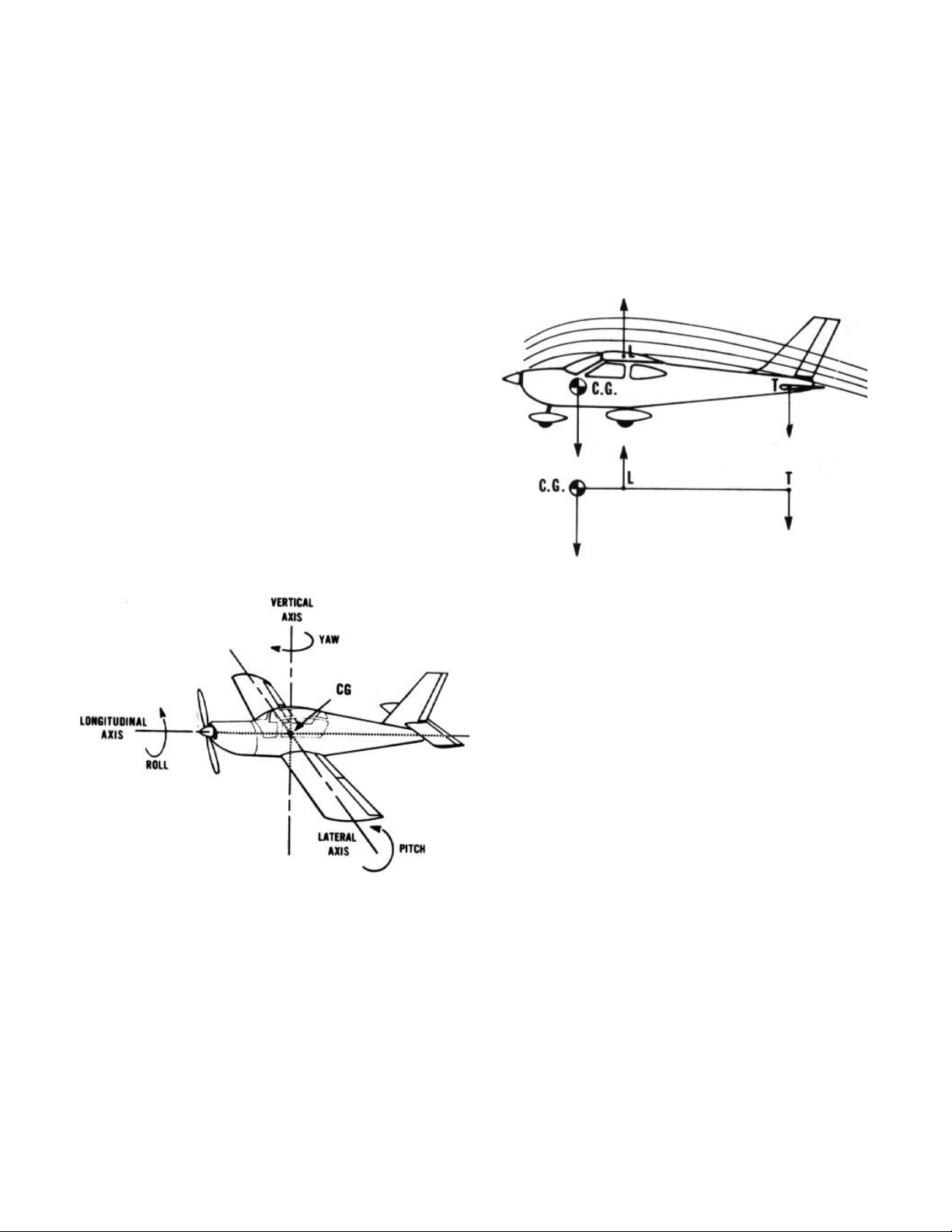
FLYING INTO THE FUTURE
■ A Short Weight and Balance Envelope
All Model 35 Bonanzas until the introduction of the
conventional- tail Bonanza Model 36 (really a Debonair) in
1968 had the original design’s 25’ 1 ¼” short fuselage.
As mentioned, short- fuselage Model 35 Bonanzas suer
from a severe aft limitation in its weight and balance envelope. It is all too easy to load these aeroplanes too far aft
without realizing it. The fact is that too often, casual general aviation pilots are not as careful about aft overloading
as they ought to be. As mentioned, even under perfect load
conditions, Model 35 Bonanza’s pitch axis control is already
highly sensitive; however, in all aeroplanes as the centre of
gravity CG moves aft, pitch sensitivity increases. If an aeroplane is aft overloaded, pitch control becomes more sensitive
than it usually is (as mentioned Bonanza’s pitch control is
quite sensitive under ordinary conditions) and the aeroplane
becomes quite unstable in the lateral axis. This combination
of control sensitivity and instability greatly increases the
chance of over- controlling into a sudden accelerated stall/
spin. As mentioned, Bonanza already has a rather abrupt
stall. Additionally, as if this isn’t bad enough, pitch sensitivity and instability caused by aft overloading becomes
greatly exacerbated at lower airspeeds, such as when rotat-
ing and climbing out after takeo and during approach and
landing – both being low altitude conditions in which stall/
spin recovery is unlikely.
CG’s position forward of the Cl. As weight (fuel, passengers,
and baggage) is loaded forward or aft of the unloaded aeroplane’s CG, the CG moves forward or aft accordingly. When
the aeroplane’s CG is within a particular range of positions
forward of the Cl, the aeroplane is within its weight and
balance envelope (see below) and is longitudinally stable. As
the CG moves aft and approaches the CL, the aeroplane’s
longitudinal stability begins to diminish until at some point
the aft load puts the CG so close to the Cl that the aeroplane
will be longitudinally unstable in pitch and, accordingly,
loaded outside of its weight and balance envelope.
■ A Brief Primer Regarding Longitudinal Stability
The lateral (pitch) axis of an aeroplane is that axis around
which the nose rises and descends. An aeroplane’s CG is that
point at which aircraft longitudinally balances on the lateral
axis. An aeroplane’s centre of lift (Cl) is that point at which
all of the aeroplane’s lifting forces (wing and horizontal
stabilizer) are focused. The distance between the locations
of the Cl and the CG determines the longitudinal stability of
the aeroplane.
When the aeroplane is fully loaded and ready for takeo,
the safe and normal position of the CG is always ahead of
the CL. The horizontal stabilizer at the rear of the aeroplane
produces sucient nose up (tail down) force to counter the
This is a typical (not Bonanza’s) loading graph. The pilot
determines the weight of each item to be loaded (left side)
and notes the moment arm (bottom).
24
A2ASIMULATIONS
:::
ACCU- SIM V3 5B BONA NZA www.a2asimulations.com
FOR SIM ULATIO N USE ONLY
Page 25

This is a typical (not Bonanza’s) loading calculator. When
the weight and moment arm of all the items to be loaded are
added together, the aeroplane must be within its weight and
balance envelope (below) or it is unsafe to y.
Here is an actual diagram of the weight and balance envelopes of all Bonanzas from Model 35 to A36. The numbers
running along the left side of the diagram indicate the gross
weight of the aeroplane and the numbers running along the
bottom of the diagram indicate the moment arm of the aeroplane from forward (left) to aft (right) measured in inches
from a specic datum point near the nose and divided by
1,000 inch- pounds. The weight and moment arm must fall
within its envelope or the aeroplane is unsafe to y.
It can be seen that earlier Bonanza models had a very
limited fore- aft loading envelope. However, as Bonanza
evolved and it carried more useful load, its weight and balance envelope expanded and aerodynamic improvements
permitted greater fore and aft loading. However, it is not
recommended that any aeroplane be own very close or
exactly at the aft edge of its weight and balance envelope
and NEVER own beyond it, even if by a tiny margin.
All Model 35 Bonanzas carry their fuel in the leading edge
of the wing which is forward of the aeroplane’s unloaded CG
and at the forward end of its weight and balance envelope.
This means that as fuel burns o, Bonanza’s CG moves aft.
Accordingly, a well- fuelled Bonanza may have been loaded
within its weight and balance envelope at takeo, however,
whilst in ight and as fuel is consumed, its CG moves aft,
possibly to or beyond the edge of its permissible aft weight
and balance limit. This Bonanza is now in a longitudinally
unstable condition and pitch control and has become highly
sensitive, perhaps actually or very nearly uncontrollable
(see above discussion). It hardly needs to be stated that a
too light and overly sensitive pitch control at landing is a de
facto unsafe ight condition.
Bonanzas up to S and V models have a rather short passenger cabin with only four seats, two up front and two
behind and a small baggage compartment behind the rear
seats. Whilst earlier Bonanzas models’ weight and balance
envelopes are quite narrow, one might expect that their
shorter cabins tended to keep aft load conditions within
safe CG limits, but apparently this was not the case in too
many situations. The last two Model 35 variants, S and V,
have optional fth and sixth passenger seats in the rear
which if lled greatly increases the chance of an aft over-
load condition. Bonanza Models S and V’s rearmost safe CG
is only slightly farther aft than earlier four seat, short- cabin
Bonanza models (see weight and balance envelope diagram
above). Recognizing this potential hazard, Beech specically
and rmly forewarned S and V model Bonanza pilots and
operators to take extra care not to load the aeroplane beyond
its published aft load limits and advised them to consider
the two rearmost seats to be child’s seats only and not to
seat adults so far aft.
A practical solution to Bonanza’s limited weight and balance envelope was largely resolved in the next major Bonanza
model, Model A36. This aeroplane is a conventional- tail
E33 Debonair with a ten- inch fuselage stretch and is powered by a 285 hp Continental IO- 520- B engine, with four
cabin windows on each side, rear starboard double entry
doors and seating for six, including the pilot. Stretching an
aeroplane’s fuselage has traditionally been a common and
eective method to increase its load capacity and exibility as well as to move the aft edge of its weight and balance
envelope further aft. Among other things, a stretched fuselage places the horizontal stabilizer father aft, increasing its
moment arm as well as moving the aeroplane’s CL farther
aft. This widens its weight and balance envelope permitting
increased aft loading. Accordingly, stretched Bonanza Model
A36’s weight and balance envelope is far wider than all earlier Bonanza models (see envelope diagram above).
■ The Elevator Downspring
From the rst Model 35 to the latest Model 36, Bonanza has
a downspring incorporated in its elevator control system.
The downspring, as its name implies, provides gentle, constant, positive forward pressure on the control wheel. This
unusual addition to the control system helps to desensitize
Bonanza’s very light pitch control and give it more “feel” in
all situations..
THE BONANZA BONANZA
The initial price of the Bonanza was $7,345 (the equiva-
lent of $82,010.71 in 2018 with a cumulative ination rate
of 1.016.6%.) A lavishly- equipped 2018 Beechcraft G36
Bonanza was recently placed on sale for $913,105, although
earlier and more modestly equipped Bonanzas are regularly
purchased for a fraction of that.
In its class and for its time, Bonanza was the epitome
of aeronautical design and engineering - fast, sturdy, and
looking like nothing which had come before. The particular historical time that Bonanza came into being and went
www.a2asimulations.com ACCU- SIM V35 B BONAN ZA
FOR SIM ULATIO N USE ONLY
:::
A2ASIMULATIONS
25
Page 26

FLYING INTO THE FUTURE
before the American aviation public is a crucial reason for its
immediate and enormous commercial success.
One important reason for Bonanza’s success when it was
introduced is that in the United States, for entirely understandable reasons, in the immediate post- war years there
was an innate and urgent desire for freshness and newness
as a sign that the coming new, more peaceful world was
going to be far better than that in which so recently and so
tragically entire nations and populations had been utterly
destroyed.
While it took most countries in Europe and Asia many
years, and in some cases, decades after the end of the war,
to signicantly recover and move forward again, the United
States, whose cities and civilian population had been spared
the cruel ravaging and devastation that had befallen most
of the rest of the world during the war, even before the war
ended was ready and able, to begin anew.
From the late summer of 1945 and throughout the 1950s
people all over the world deeply desired and worked hard
to create a new beginning. A new, clean, peaceful and
prosperous world had been promised, and now, for some,
it was in their grasp. In the United States, everything from
buildings to automobiles to kitchen appliances to furniture to the new, retractable ballpoint pens took on a clean,
“streamlined” and modern look. The stodgy, old, heavily
riveted, ornately carved, massive, dark antique appearance
of much of what had dened the pre- war world was now
considered more than simply “old- fashioned.” In a tacit
but very substantial way, the artifacts of the pre- war world
and culture were a sore and uncomfortable reminder of how
that world and culture had so utterly failed humanity. Many
of these things were thrown or given away or were put in
the attic or the basement, out of sight. Accordingly, decades
passed before “antique” or “used” furniture and objects
regained popular appreciation and value. After the war all
that was “new” and, most particularly, that which was not
at all like what was old, was in high demand.
These are a few magazine advertisements which give a
good sense of the avour of this post- war feeling:
It was into this supercharged, sociologically, historically
No wonde r he’s smiling.
A2ASIMULATIONS
26
:::
ACCU- SIM V3 5B BONA NZA www.a2asimulations.com
FOR SIM ULATIO N USE ONLY
Page 27

www.a2asimulations.com ACCU- SIM V35 B BONAN ZA
FOR SIM ULATIO N USE ONLY
:::
A2ASIMULATIONS
27
Page 28

FLYING INTO THE FUTURE
Still sleek and mode rn looking, this is Beech Model 35 version 4. I t is currently being displaye d
in the Nati onal Air and Space Museum of the S mithsonian on the National Ma ll in Washington
D. C. as Cap tain William Odom’s “Waikiki Be ech.” Whilst this is the oldes t flyable Bee ch Model
35, it is not currentl y flight- worthy. Note the large tip - tanks installe d for the record 19 49 flight.
and psychologically nova- venerating American culture that
Beechcraft introduced its Bonanza in 1947. It was no coincidence that Bonanza was ready- made for those times. It
epitomized them. Those who were in the market for the
nest and most modern of personal or business aeroplanes
and could aord its price lined up to place their orders.
In fact, it was this enormously positive response to the
Bonanza in 1947 that fueled many GA aircraft manufacturer’s starry- eyed optimism and belief in an aviation sales
boom that never happened.
Beechcraft’s goal and expectations for the Bonanza were
clear from the outset – to create the fastest aeroplane for
its horsepower that could carry up to four in comfort and
which would be purchased primarily by corporations and
businesses for use as a luxury executive transport. Visually
stunning, made of the same materials and being of the
same design philosophy as current front- line ghter aircraft, promising spectacular performance whilst powered
by a modestly- sized and economical- to- operate engine
and presenting a futuristic “new world” look and attitude,
Beech Model 35 Bonanza hit every note and nerve, clicked
on every button and twanged every heart string.
Unfortunately for most, although a part of Beech’s plan,
only those with a great deal of hard cash could buy into the
Bonanza club. Of course, nancial ability does not necessarily imply aeronautical ability or experience. Far too many
private Bonanza owners in those rst post- war years were
woefully unprepared to y it safely.
IS THE “V”- TAIL BONANZA SAFE?
Let me say at the outset of this topic discussion that “V”-
tail Bonanza, and all properly designed and competently
built aeroplanes for that matter, are ultimately only as
safe as the competency and diligence of their pilots. Proper
maintenance and inspection along with careful and knowl-
edgeable piloting are the requisites for all safe ight.
cient cruisers. They get the most out of the power available and they go fast. Unfortunately, that is not the totality
of the matter. “Clean” aeroplanes, like Bonanza, also tend
to be challenging for those pilots who are unfamiliar with
the ight characteristics of such aircraft. The problem is
that when a clean aeroplane’s nose goes below its normal
cruising attitude with power on, the aeroplane accelerates
at a very high rate, far faster than anything in which most
casual general aviation pilots might have trained or previ-
ously own. As the airspeed indicator rapidly winds past the
end of the green arc (VNO – maximum structural cruising
speed) into and through the yellow arc (cautionary maneou-
vering airspeeds) and towards and beyond the red line (VNE
– never exceed airspeed,) the situation is often already too
late for all but the most careful and knowledgable pilots to
correct (and likely too late for even them, as well).
All pilots know that to reduce airspeed, the nose must be
raised by pulling back on the control stick/yoke, increasing the aeroplane’s Alpha which, in turn, creates a positive
g- force (accelerative force applied in addition to the force
of gravity) on the aeroplane and those onboard. However,
when airspeed is at a critically high level, it is possible,
perhaps likely, that even the smallest amount of rearward
control stick/yoke pressure will create a powerful positive
g- force sucient to overload the aeroplane’s wings and tail
structures, causing a catastrophic failure thereof. In extreme
circumstances, even the gentlest pull on the controls when
the airspeed needle is at, or worse, beyond the red line will
instantly cause such dire consequences. Not doing anything
is no solution either.
Once the aeroplane is past the redline it is under tremendous structural stress. Every second is crucial and recov-
ery which safely and eectively lowers the airspeed must be
done right now! Closing the throttle is, of course, the rst
thing to do in such a situation, but that might not be su-
cient to avoid a tragedy. If you have a speed brake, of course,
However, it is not a secret that
early “V”- tail Bonanzas have had a
poor safety record. Many have blamed
the “V”- tail for this, but that is not
entirely fair. Other more important
factors have been found to have been
responsible for this record. It appears
that the greatest reason why there
were so many early fatal Bonanza
accidents is that the aeroplane was
simply ahead of its time and more of
a handful than most general aviation
pilots could then handle. General aviation pilots in the late 1940s and early
1950s were not used to aircraft as
clean and demanding as Bonanza, and
why should they have been? Nothing
like Bonanza had previously been
available to them.
Aerodynamically “clean” (low drag)
aeroplanes are excellent and e-
28
A2ASIMULATIONS
:::
ACCU- SIM V3 5B BONA NZA www.a2asimulations.com
FOR SIM ULATIO N USE ONLY
Page 29

extend it immediately, but speed brakes are not installed in
Bonanzas nor in virtually any other general aviation air-
craft. Trying to lower the undercarriage and/or aps to slow
down at such a high airspeed is very risky may not work.
Additionally, doing this is likely to cause just the serious
structural damage you are trying to avoid. In fact, once you
are hurtling past the redline there may be no way to avoid
a tragedy.
With this in mind, it is well to be aware that in nearly
all fatal Bonanza accidents in which a failure of the aircraft’s structure was involved, it was determined that the
aeroplane had been own outside its normal ight envelope (i.e., ying too damn fast). In most instances these
accidents were preceded by loss of control due to the pilot’s
apparent misinterpretation of the aeroplane’s situation
causing him/her to make incorrect control inputs, exacerbating rather than correcting the problem.
When Bonanza was introduced in 1947, very few pilots
were trained or competent to y in what is called “instrument ight rules” (IFR) conditions, which are essentially
those in which the pilot is unable to see the horizon and is
unable to accurately and safely y the aeroplane without
reference to instruments. At this time not even many exmilitary pilots had much IFR training or experience and the
vast majority of civilian pilots had even less. The IFR navi-
gation system, so sophisticated, ecient and ubiquitous in
modern times, was in its bare infancy in early 1950s and
virtually non- existent in the late 1940s. In that era gyroscopic instruments, common today and which are a crucial
aid during IFR ight, were not standard or even available
equipment in early Bonanzas and most of the other general
aviation aeroplanes.
When the weather obscures or completely hides the hori-
zon, safe ight becomes dependant upon the pilot’s ability to y the aeroplane with sole reference to and reliance
upon what instruments may be on the panel. Yes, IFR ying
can be done without gyros and learning to do so is a part of
IFR training, but doing this eectively requires professional
instruction and lots of practice.
Unless an auto- pilot has been engaged, even a welltrimmed aeroplane will not maintain straight and level
ight by itself for very long. Even assuming perfectly calm
winds (which is rarely the case, particularly at altitude,) the
torque of the engine and propeller causes a steady left banking tendency which is likely to go unnoticed unless the pilot
has reference to the horizon (real or gyroscopic), the terrain
and/or notices that the aircraft’s compass heading is slowly
changing.
An ordinary magnetic compass (sometimes called a
“whisky compass” for its visible yellow/brown- coloured
lubricating oil) is notoriously inaccurate and misleading
under many ight conditions and is considered to be unreliable as the sole source of heading information during IFR
ight. An aeroplane out of true rigging, subtle trim inaccuracies, gusts of wind and/or turbulence may cause pitch and
roll changes as well, all of which may also go unnoticed by a
pilot not trained to y in IFR conditions.
As mentioned, pilots have reported that “V”- tail
Bonanzas are very light and sensitive in pitch to the extent
that ying a “V”- tail Bonanza has been described as being
“sportscar- like.” Also, “V”- tail Bonanzas are notoriously
unsteady in pitch and roll, tending to constantly “seek”
pitch position and laterally wander from level ight. Beech
designed Bonanza for maximum performance with little to
no considerations or compromises for ight by low- time
pilots. Whilst Bonanza’s “sportscar- like” – perhaps even
“warbird- like” – ight characteristics may be quite satisfying to an experienced pilot, when in IFR conditions these
characteristics are likely to create an unintended and unnoticed banked, nose down condition. When these are combined what is called a “spiral dive” is likely to occur.
Over many decades of close and diligent study of fatal
general aviation aircraft accidents and reports from ight
instructors, the loss of a visual horizon has been cited as the
most common cause of the spiral dive phenomenon and the
fatal accident which soon and inevitably follows. It has been
determined by a number of ight instructors that if a pilot
without an instrument rating tries to turn around in IFR
conditions to y back to clear weather he /she is likely to
mishandle the turn by not applying sucient back pressure
on the yoke/stick, thereby allowing the nose to drop. Add to
this banked attitude the aerodynamically clean Bonanza’s
tendency to quickly accelerate to and beyond its redline
(Vne) when the nose drops, and therein exists a formula
for catastrophe that is, as is said, “Just waiting to happen.”
What happens all- too- often is this: a pilot inadvertently
and/or negligently ies into a low - visibility weather condition and soon loses sight of the horizon. If not trained to
y in IFR conditions and relying upon his/her “senses,”
11
he/she “feels” that all is well all whilst the left wing has
already slightly dropped and, because the aeroplane is no
longer ying level, the nose has also begun to drop. As mentioned, this situation is exacerbated if this pilot attempts a
turn in IFR conditions. What this pilot usually then hears
is the rising sound of the outside air ow and immediately
sees the airspeed indicator needle quickly rising. He/she
naturally pulls back on the control wheel to alleviate this
but, because the aeroplane’s wings are no longer level, up
elevator input only steepens the left bank which, accordingly, causes the nose to drop further. Meanwhile, airspeed
continues to increase until it is quickly well past the redline
as the pilot frantically but vainly pulls back even harder on
the control wheel to slow the airplane. This continues for
only a short while until either the wings and/or tail structures fail or the aeroplane contacts the ground in a sharp
nose- down left bank at a very high speed.
This is, in fact, what apparently happened to John
Kennedy, Jr. on July 16, 1999 when his high- performance,
high- powered and aerodynamically clean Piper PA32R
“Saratoga,” which he had recently purchased and in which
he had little ight time, crashed into the Atlantic Ocean
o the coast of Martha’s Vineyard, Massachusetts, kill-
ing all three on board (Kennedy, his wife Carolyn and his
sister- in- law Lauren Bessette). On that day, Kennedy had
www.a2asimulations.com ACCU- SIM V35 B BONAN ZA
FOR SIM ULATIO N USE ONLY
:::
A2ASIMULATIONS
29
Page 30

FLYING INTO THE FUTURE
been delayed by business and did not takeo from Essex
County Airport, near Faireld, New Jersey to attend the
wedding of his cousin Rory Kennedy at Martha’s Vineyard,
Massachusetts until almost sunset. He soon found himself ying in the dark of the evening in very hazy, humid
low- visibility weather, always a perilous ight condition
for VFR ying. At some point he apparently lost clear sight
and sense of the horizon and became spatially disoriented
(see footnote below.) The installed sophisticated threeaxis autopilot was not engaged and he was not instrument
rated. Kennedy’s “Saratoga” crashed into the ocean at an
extremely high speed in a steep left bank and with the nose
steeply down.
All of the foregoing is not to say that Model 33 Debonairs
and later the Model 36 Bonanzas with conventional tails
did not occasionally have fatal accidents, including those
involving a pilots’ loss of control in IFR weather. The difference was that in these accidents, the tail surfaces were
found not to have failed in ight and were not considered to
be a signicant factor in these accidents. It was determined
that the ruddervators of the early “V”- tail Bonanzas tended
to fail early in the course of an over- speed situation, whilst
conventional- tail Bonanzas and Debonairs were discovered
to have granted a bit more time for a pilot to extricate him/
herself from the overspeed situation before the tail surfaces
departed.
Of course, Beech took this matter extremely seriously and
from Bonanza C35 (late 1950 to 1952) onward, the chord
(leading to trailing edge) of the ruddervators was increased
by seven inches, putting the non- moving stabilizer part of
the ruddervator sixteen inches ahead of its main spar. On
early Bonanzas up to model C- 35 the ruddervators’ main
spars were their sole attachment points to the fuselage. The
problem was that with this increase in area, an even larger
part of the ruddervator was now unattached to the fuselage.
This redesign was a logical attempt to create a more stable
and less sensitive pitch control by increasing the overall area
of the ruddervators. Unfortunately, the ruddervators’ internal structure was not similarly enhanced, which some have
speculated was because of Beech’s apparent reluctance to
ocially and publicly acknowledge that there was anything
fundamentally wrong with the original “V”- tail design to
begin with.
In addition to the increase in the ruddervators’ area,
Bonanza C35 has a more powerful Continental E- 185- 11
engine, upping the hp from 165 hp to 205 hp for one minute
and 185 hp continuous, all of which make it a very desirable
and sought- after early Bonanza.
Unfortunately, not anchoring the ruddervators more
securely in C35, such as at their leading edges as well as the
spar, caused a number of in- air ruddervator failures which,
in turn, caused the wings to fail as well. All of these accidents occurred after the aeroplane had been own at airspeeds beyond the redline (Vne,) as occurs in an uncontrolled spiral dive. Based upon inspection of the wreckage of
these crashed aeroplanes, Beech ultimately determined that
Bonanza’s ruddervators would henceforth be required to be
attached to the fuselage at both the spar and leading edge.
This x was eective and thereafter the number of
Bonanzas which crashed due to tail surface collapse or
departure decreased. Recovering to level ight from airspeeds higher than the redline no longer tended to cause
immediate airframe disintegration and in some instances
with careful handling, a pilot could now extricate such a
hurtling Bonanza from its dive to level
ight without incident.
Piper PA- 32R “Saratoga.” This adv anced and very high- perfo rmance aeroplane was initially called
“Piper Lance,” a retra ctable undercarriag e Piper PA- 32 Che rokee Six. As this aeroplane evolved it
becam e known as Piper “Saratoga.” Similar to Lance in m ost ways, Saratoga has a tap ered wing,
whilst Lance’s wing is Cherokee Six’s un- tapered “Hershey Bar” t ype.
30
A2ASIMULATIONS
:::
ACCU- SIM V3 5B BONA NZA www.a2asimulations.com
FOR SIM ULATIO N USE ONLY
“ALRIGHT, WE GET IT”
Whilst spokespersons for Beech are
not known to have actually publicly
said this or acknowledged “V” - tail
Bonanza’s deciencies, Beech certainly tacitly made such a statement
when, in 1959, Model 33 “Debonair”,
essentially a conventional- tail
Bonanza, was introduced. Surely this
was a strong response to the burgeoning criticism and the historically poor safety record of “V”- tail
Bonanza. At this or any time Beech
could have simply changed to a conventional tail arrangement whilst
retaining the Bonanza name, as it
actually did in 1968 with the introduction of the conventional- tail
Model 36 “Bonanza.” The introduction of “Debonair,” a new non- “V”tail Beech aeroplane, was Beech’s
clear invitation to “V”- tail sceptics
Page 31

and critics to purchase a Beech aeroplane that in every substantial way is everything that Bonanza is, but with a reassuring (for some) conventional- tail.
As the years passed fewer and fewer Bonanza fatal accidents were reported and its accident rate became comparable
to other similar aircraft. In addition to the mentioned structural improvements in Bonanza perhaps the most important reason for this improvement in safety has nothing to
do with Bonanza at all. What happened was that throughout
the 1950s and into the 1960s private pilot training greatly
improved, and FAA checkout requirements for pilots who
ew or sought to y high- performance aircraft such as
Bonanza was made more rigourous. Wealthy “Doctors” and
others who purchased or regularly ew Bonanzas were carefully taught how to y such a high- performance aeroplane.
Equally important, as time passed, moiré and more elemen-
tary IFR and “extreme attitude recovery” training was added
to the private pilot training curriculum (FAR- 14 CFR Part
61 ;). Whilst not in any way comparable to or a replacement
for an Instrument Rating, even this rudimentary instrument
training on many occasions was a life- saving aid to many
pilots who found themselves in low visibility weather. Most
ying clubs and aircraft rental businesses wisely require
that a pilot must hold a current Instrument Rating in order
to y high- performance aircraft such as Bonanza.
To be fair to Bonanza, all aircraft are and always have been
in danger of airframe destruction when own beyond their
ight envelopes, a condition which clean, high- powered
aircraft tend to enter with greater ease and frequency than
other less slippery and less powerful aircraft, and/or when
own by pilots whose aeronautical experience is not equal
to the aeroplane which they are ying.
Bonanza’s improved accident rate throughout the 1950s
and into the 1960s did not, however, prevent certain factions, who had reasons of their own, to continue to dispar-
age “V”- Tail Bonanzas. Not the least of these was William
T. Piper and Co. who in 1956 was developing Piper PA- 24
“Comanche,” which Mr. Piper hoped and publicly stated
would be “The Bonanza Killer.” Whilst Comanche is a superb
aeroplane, in every way comparable and in some ways superior to Bonanza, neither it nor any other aeroplane has ever
been able to “kill” Bonanza. Since Bonanza’s introduction
it has been the icon at the top of the hill of general aviation
aircraft and is likely to remain so for quite some time.
THE BONANZA LEGACY
Still in production, since 1947 more than 17,000 Beech
Bonanzas have been produced. Of these, more than 12,000
Bonanzas of every variation are currently listed in FAA’s
aircraft registry which well- attests to Beech build quality. In all of its 37 variations (and counting,) Bonanza is
the sixth most numerously produced general aviation aeroplane, not far behind the 20,000- plus Piper J- 3 “Cubs.” To
date (2018,) Bonanza is the 15th most numerous aeroplane
of any kind.
Many of the earliest Bonanzas have gone the way of
normal attrition due to age and wear, but a good number
Beech cra Bonanza V 35B – a study in gra ce
and power. The last “V ”- tail Bonanza, not
at all coincidentall y designated V3 5 was
introdu ced in 1966. Mino r improvements to
it were made in V35A (19 68- 69) and many
more in V35B (1970- 8 2.)
of these have been and are being restored back to ight-
worthy condition by loving owners and operators. Over the
71 years since Bonanza was rst introduced, it has justly
earned the respect of the general aviation community as
well as the deep aection of its owners and pilots.
THE END OF AN ERA - BEECHCRAFT
MODEL V35B “BONANZA”
V35B, rst produced in 1970, is the specic aircraft that
A2A has developed as our latest ight simulation oering.
From its rst iteration in 1947 as Model 35, Bonanza has
constantly been improved and has greatly evolved. Almost
every year or so a new letter model Bonanza has been produced, each one an improvement over those which came
before. After sixteen “V”- tail model Bonanzas, from the
1947 Model 35 to the 1964- 65 S35, every aspect of the aeroplane has been upgraded to maintain Bonanza’s reputation
as the highest quality and best performing aeroplane in its
class.
On 29 November 1950, Olive Ann Beech, a co- founder
of Beech Aircraft Company, became its President after her
husband and co- founder, Walter Herschel Beech, suered a
www.a2asimulations.com ACCU- SIM V35 B BONAN ZA
FOR SIM ULATIO N USE ONLY
:::
A2ASIMULATIONS
31
Page 32

FLYING INTO THE FUTURE
sudden and fatal heart attack. She remained at Beech’s helm
until it was purchased by Raytheon Company on 8 February
1980. With this sale Beech Aircraft Corporation was, for the
rst time, no longer headed by a Beech family member. In
1982, Raytheon Company decided to close the era of the
“V”- tail Bonanza. Whether this would have occurred if
Olive had still been Beech’s president is a matter for interesting speculation.
Appropriately, Raytheon/Beech skipped Model 35T and
35U designations and went right to Model V35 for the last
“V”- tail Bonanza. V35B retains the basic V35 nomenclature; however, the 35B is, in fact, a new model. V35B features a completely new interior with additional headroom
including redesigned and improved seats, a new instrument
32
A2ASIMULATIONS
:::
ACCU- SIM V3 5B BONA NZA www.a2asimulations.com
FOR SIM ULATIO N USE ONLY
panel and a more ecient ventilation system. The exterior remains essentially the same as V35, however V35B has
a new paint scheme. The price of a V35B was $41,600 in
1972 ($248,359.96 in 2018 with an a cumulative ination
of 497%).
Model V35B, along with a turbo- charged variant, V35B- TC,
was produced from 1970 - 82. It would be the last of the
breed. The rst conventional- tailed Bonanza (an oxymoron
to some) was the 1968- 69 Model E33, basically a re- named
continuation of the Debonair line. Model 36 Bonanza is an
E33A with ten inches added to the fuselage, four cabin windows on each side, right- side double- doors and six seats.
From that time to the present there have been no new “V”tail Bonanzas.
Page 33

SPECIFICATION
Model Model V35B
Engine 1 x Continental IO- 520- BB flat- six piston engine, 213kW
Weights
Take- o weight 1,542 kg 3,400 lb
Empty weight 955 kg 2,105 lb
DIMENSIONS
Wingspan 10.21 m 34 6 in
Length 8.05 m 26 5 in
Height 2.31 m 8 7 in
Wing area 16.81 m2 180.94 sq
PERFORMANCE
Max. speed 338 km/h 210 mph
Cruise speed 253 km/h 157 mph
Ceiling 5445 m 17850
Range 1,648 km 1,024 miles
BEECHCRAFT BONANZA V35B
PRODUCTION YEARS: 1970- 1982
SERIAL NUMBERS: D- 7977 thru D- 8598
ENGINE: Continental IO- 520B 285 hp
DISTINGUISHING FEATURES
• Trapezoidal long rear windows
• Long- chord stabilators
• Stinger tail cone
• One- piece windshield (no center strip)
• Ventilation inlet scoop between stabilators
• Single, throw- over control yoke
• Vernier (twist operation) engine and mixture controls
• Gear handle on right, flap on left
• Gear- driven alternator
• Extended aft baggage area
COMMON OPTIONS AND MODIFICATIONS
• Long- range fuel (two 40- gallon tanks)
• V35TC - TSIO- 520D STC
• Other engine upgrades
• Forward facing “family” 5th and 6th
seats in aft baggage area
• Tip tanks
• Large aft baggage door
• Improved cabin ventilation system
OUR NEW BIRD
We hope that you will nd ying A2A’s Bonanza V35B to be
an enjoyable, authentic and satisfying experience. Many of
those on our Beta Development Team, including this writer,
have cumulatively had many hundreds of hours ying a
number of full- size Bonanza variants, including V35B and
some of us have instructed in them. It is universally held
amongst us that all Bonanzas are high- quality, beautifully
performing aeroplanes which y with grace and élan. We
have put all of our collective experience into assuring that
A2A’s V35B Bonanza is as accurate and enjoyable a simula-
tion of the full- size aeroplane as possible. We are condent
that once you, too, have own A2A’s V35B “Bonanza,” you
will come to feel this way as well.
www.a2asimulations.com ACCU- SIM V35 B BONAN ZA
FOR SIM ULATIO N USE ONLY
• Dual control yoke
• Avionics upgrades
:::
A2ASIMULATIONS
33
Page 34

FLYING INTO THE FUTURE
ENDNOTES
TWA (Transcontinental and Western
Airlines) Flight 599 was a ight
1
from Kansas City, Missouri to Los
Angeles, California on 31 March 1931.
There were a number of stops sched-
uled along the way. The rst stop after
taking o from Kansas City was to be
Wichita, Kansas. The Fokker F.10 Trimotor with eight passengers aboard
never made it to Wichita. It crashed into
a wheat eld a few miles southwest of
Bazaar, Kansas, a little more than halfway to Wichita, killing all on board,
including Knute Rockne. The nation
mourned as if a President had died, and
President Hoover called Rockne’s death
“a national loss,” such was Rockne’s
popularity and fame.
Public outcry at Rockne’s death in the
crash prompted aviation ocials and
experts to commence what was the rst
extensive ocial study of a crashed
aircraft’s wreckage as well as a detailed
scientic analysis of the cause of the
crash, setting an intensive aeronautical forensic standard that continues to
this day. TWA’s rst explanation was
that the Fokker was brought down by
extreme turbulence. The evidence presented for this theory was that the copilot had made a radio call to Wichita
after an hour into the ight, saying,
“The weather here is getting tough.
We’re going to turn around and go back
to Kansas City.” Another theory that
TWA posited was that the Tri- motor
ew into undetectable and unreported
clear- air turbulence which overstressed
its wing, causing it to fail. At that time
clear- air turbulence was not nearly as
well understood as it became in later
years.
Before long it was clear that the
actual and ocially recognized cause
of the crash of TWA Flight 599 was the
break- up and departure of the Fokker’s
wooden wings. TWA’s attempts to
blame weather conditions for the crash
were quickly shown to be erroneous.
Upon close inspection, the cause of the
wings’ break- up was determined to be
the partial interior delaminating of the
wings’ plywood skin which was bonded
to the ribs and spars with water- based
aliphatic- resin glue. The aircraft’s pre-
vious ights in rain and its exposure to
rain and moisture on the ground had
deteriorated the glue bond inside the
wing to the extent that sections of the
plywood covering had eventually sepa-
rated from its under- structure in ight.
It was deemed that given the type of
glue and the materials used in the construction of the wing that the eventual
separation of the wings’ plywood skin
and the wings’ subsequent catastrophic
break- up was inevitable. The accident was, of course, a terrible misfortune; however, the tragic loss of such a
beloved public gure and the publicity
that it created sparked the beginning
of a new and more enlightened era in
aviation accident forensics and caused
the immediate institution of dozens of
safety regulations.
One of the positive changes which
were made was with regard to more
regular and intensive inspection of
commercial aircraft. As might be
expected, after the Rockne crash and
the widely published ocial report of
its cause, wooden- winged aeroplanes
went distinctly out of favour. In particular, the wooden- wing Fokker F.10 was
no longer trusted by the public, most of
who refused to y in them. TWA, which
operated many Fokkers, nearly went
out of business. The slower but allmetal Ford Tri- Motor was substituted
for Fokkers in many instances, setting the stage for future all- metal airliners such as Boeing 247 and Douglas
DC- 2/3.
Lyric from the song, “New Sun in
the Sky” appearing in the 1953 lm
2
“The Band Wagon” written by Betty
Comden, Adolph Green and Alan Jay
Lerner
Medal of Honor recipient U. S.
Marine Corps Colonel Gregory
3
“Pappy” Boyington may have put it
best when he said, “(Combat) ying is
hours and hours of boredom sprinkled
with a few seconds of sheer terror.”
It was not until 1963 that Beechcraft
produced its rst “sport” type
4
aeroplane to compete with Piper’s
PA- 28 “Cherokee” line and Cessna’s
172 “Skyhawk.” The rst of Beech’s
low- to- middle line aeroplanes was
the xed tricycle- undercarriage entry-
level Model 23 “Musketeer,” a number
of versions of which were produced
during the 1960s with increased power
and seating intended for the low- tomiddle level sport aircraft market.
In 1966 Beech Model 19, “Musketeer
Sport,” a toned- down, lower- powered,
lower- priced version of Model 23
“Musketeer” was produced, intended to
be a trainer which would be attractive to
ying schools and clubs as competition
to the wildly popular Piper Cherokee
140 and Cessna 150. From 1966 to 1979,
models A19, B 19 and M19 “Musketeer
Sport” versions were built with engine
and interior upgrades. Simultaneously
with the Model 19 trainer, Beech produced Beechcraft 23- 24 Musketeer
Super III, an upgraded, more powerful xed tricycle- undercarriage version of Model 23. The last of the Beech
“Musketeer” aircraft was the retractable undercarriage Model 24 “Sierra,”
developed to be similar to and compete
with the popular Piper PA- 28R- 200
“Arrow” which was essentially a
retractable undercarriage Cherokee
180/Archer with a 200 hp fuel injected
engine turning a constant- speed
propeller.
Whilst Beech Bonanza and Debonair
have ruled the high- end, high performance light aeroplane market since
their inceptions, none of the excellent
“Musketeer/Sierra” series were nearly
as popular, commercially successful or
as market competitive as their Piper
and Cessna counterparts.
English usage of “bonanza” dates
back to at least 1829, primarily
5
in the United States. Basic denitions
include “a thing that produces excellent results” and “a great quantity of
something of value.” It was also commonly used, particularly in the 19th
century American West to describe a
34
A2ASIMULATIONS
:::
ACCU- SIM V3 5B BONA NZA www.a2asimulations.com
FOR SIM ULATIO N USE ONLY
Page 35

large deposit of rich minerals such as
gold or silver. This usage seems likely
to be that which generated the name of
the popular American television series
(1959- 73) of that name.
Etymology- The English word
“bonanza” is taken from the modern
Spanish language. In Spanish,
“bonanza” literally means “calm sea,”
which implies prosperity and also refers
to a rich cargo or nd. This is derived
from the Vulgar Latin [Vulgar Latin
or Sermo Vulgaris meaning “common
speech” was the non- standard form(s)
of Latin (as opposed to the classical]
spoken in the Mediterranean region
during and after the classical period
of the Roman Empire) “bonacia.”.
“Bonacia” is a combination of the Latin
“bonus,” which means “good,” and
“malacia,” which means “calm sea.” In
turn, “malacia” comes from the Greek
“malakia,” which means “softness.”
Beech Baron B55 and B58 twins
also use this airfoil
6
As has been said of Messerschmitt
BF- 109, also not considered to be
7
a particularly pilot- friendly aeroplane,
“The pilot is not to expect it to perform,
it expects the pilot to.”
As calculated by both Beech and the
CAA, (forerunner of the FAA) Beech
Model 35’s fatal accident rate was, from
1947 through 1952, a whopping 4.90
per 100,000 ight hours. The following
Models A35, B35 and C35 were reported
to have a fatal accident rate over the
same period of 2.50 per 100,000 ight
hours. By comparison, the contemporary
Cessna 195’s fatal accident rate over the
same period was reported to be approxi-
mately 2.0 per 100,000 ight hours and
Beech 18’s fatal accident rate over the
same period was reported to be only
.80 per 100,000 ight hours. As a comparison to a current high- performance
aeroplane, studies show that as of 2018 a
modern day Bonanza equivalent, Cirrus
SR- 20, has averaged a fatal accident rate
of 1.63 per 100,000 hours, less than ⅓
the rate of the 1947 Model 35 Bonanza
during its rst six years.
Ground Eect is that condi-
tion which begins when an aero-
8
plane is approximately the length of
its wingspan above the ground and
is maximized when it is at approximately 1/5th of its wingspan above the
ground. When in ground eect, the
aeroplane glides more eciently and
airspeed decreases more slowly. This
may cause touchdown to occur much
farther down he runway than the pilot
anticipated, sometimes so far that the
aeroplane could be in danger of running
out of runway. Ground Eect is caused
by the disruption of the wingtip vortices and the downwash at the wing’s
trailing edge (which are always gen-
erated by the wing when in ight) by
contact with the ground. This disruption limits the size of the vortices and
alters the direction of the downwash
which becomes more vertical, increasing lift but also reducing drag (opposite and equal reaction). The altered
angle of lift reduces Induced Drag
which accordingly reduces the rate at
which the aeroplane decelerates. It is
the combination of additional lift and
reduced drag which causes the aero-
plane to oat above the runway when
in Ground Eect.
4 CFR 91.109 states: “No person
may operate a civil aircraft (except
9
a manned free balloon) that is being
used for ight instruction unless that
aircraft has fully functioning dual
controls. However, instrument ight
instruction may be given in a singleengine airplane equipped with a single,
functioning throwover control wheel in
place of xed, dual controls of the elevator and ailerons when—
(1) The instructor has determined
that the ight can be conducted safely;
and
(2) The person manipulating the
controls has at least a private pilot cer-
ticate with appropriate category and
class ratings.
3) Except in the case of lighter- thanair aircraft, that aircraft is equipped
with fully functioning dual controls.
However, simulated instrument ight
may be conducted in a single- engine
airplane, equipped with a single, functioning, throwover control wheel, in
place of xed, dual controls of the elevator and ailerons, when—
(i) The safety pilot has determined
that the ight can be conducted safely;
and
(ii) The person manipulating the
controls has at least a private pilot cer-
ticate with appropriate category and
class ratings.”.
The Bonanza/Baron/Travel- Air
Pilot Prociency Program, Inc.
10
(BPPP), created and overseen by the
American Bonanza Society Air Safety
Foundation, holds a CFR exemption allowing the use of single- yoke
equipped aircraft (single- and multiengine) for recurrency training. The
exemption is valid only during approved
BPPP classes. Like many others, I took
my Bonanza check ride before this
exemption was instituted.
E xtensive studies dating from as
early as the 1930s have shown that
11
a pilot in a moving aeroplane without
reference to the horizon and/or without a clear view of the outside world
will often completely misinterpret the
actual attitude of the aeroplane, and
how it is actually moving. This phenomena is called “spatial disorientation”, i.e., the failure to maintain body
orientation and posture in relation to
the surrounding environment (physical space) when at rest and especially
during motion. This is caused by the
incorrect response of the pilot’s vestibular (organs of equilibrium located
in the inner ear) and proprioceptive
(muscle spindles in skeletal striated
muscles and tendons) systems as follows: the aeroplane’s acceleration and
turning as well as centrifugal and inertial forces all act upon the pilot’s inner
ear which informs the net gravitoinertial force which the pilot perceives. The
pilot’s Otolith organs, the Utricle and
Sacculus become misaligned with gravity which leads to spatial misjudgement
and disorientation.
www.a2asimulations.com ACCU- SIM V35 B BONAN ZA
FOR SIM ULATIO N USE ONLY
:::
A2ASIMULATIONS
35
Page 36

DEVELOPER’S NOTES
36
A2ASIMULATIONS
:::
ACCU- SIM V3 5B BONA NZA www.a2asimulations.com
FOR SIM ULATIO N USE ONLY
Page 37

ome say the hardest thing for an artist
to draw is the human hand, because
it is the part of our body that we are
all most familiar with. Simulating the
S
ing that human hand. Additionally, there are many
Bonanza variants through history with owners that
know their airplane in some ways better than they
know themselves.
Yet we all interpret life around us dierently,
including how an airplane feels to each pilot. It is
up to us, at A2A, to not just create an airplane that
objectively performs in line with the actual airplane,
but to capture that human feel and interaction with
the real airplane. We have to somehow magically
capture that experience that applies to all pilots.
And Accu-Sim technology allows us to achieve this
better than anything we’ve used before.
Beyond modeling a specic airplane, the Bonanza
history is surrounded with tales and stories developed over many decades, some are true and some
not. Probably the most common nick name the
Bonanza V-tail is known for is being the “doctor
killer.” When the Bonanza was rst introduced, it
was unlike anything anyone has ever seen in the
general aviation market. And for the decade following it’s release, successful businessmen and professionals were buying the Bonanza in great numbers. Many of these pilots had primary careers that
demanded a great deal of their time, not leaving
much room for ying. And like many “weekend
warriors” today who spend the whole week sitting
behind a desk then go out and play a sport on the
weekend, injuries erupt. The same holds true for
the busy professional working all week who then
Beechcraft Bonanza V-tail is like draw-
decides to occasionally y a high performance airplane like the Beechcraft Bonanza V-tail.
The V-tail Bonanza was built from World War II
ghter technology, which was designed for highly
trained professional pilots. And like most Warbirds,
the Bonanza want so y fast, all the time. Unlike
general aviation aircraft that were developed in
later years to have benign ight characteristics,
the Bonanza inherently has all of the challeng-
ing qualities of the World War II ghter. From my
point of view, ying a Bonanza is just like ying a
Warbird. It rumbles, shakes, rattles, is heavy and
can bite the low time pilot in a heart beat. Therefore
it’s this writer’s opinion that the new pilot should
approach ying a V-tail Bonanza exactly the same
as approaching an aircraft like a P-51 Mustang. The
V-tail Bonanza, like the Warbird, is designed for
experienced pilots who take the time to study and
y and operate such an aircraft with organization,
patients, and preparedness.
For those pilots who do approach the V-tail
Bonanza with the respect it deserves, it will reward
the pilot with an experience unlike any other air-
craft in the general aviation eet today. It is for this
reason the V-tail Bonanza still stands alone today,
as it did on the rst day it was introduced to the
public.
We hope our work on this aircraft meets and
exceeds all of our customers expectations, and also
hope this aircraft delivers not weeks or months, but
years of excitement, wonder, surprise, and the most
complete simulated aviation experience to date.
Thank you to all of our customers for allowing us
to pursue our dreams, and hopefully help pass our
dreams onto you too.
A2A Simulations Inc.
www.a2asimulations.com ACCU- SIM V35 B BONAN ZA
FOR SIM ULATIO N USE ONLY
Scott
Founder
:::
A2ASIMULATIONS
37
Page 38

FEATURES
n Aircraft DNA technology re-creates actual
engine and airframe vibrations.
n V-tail physical modeling captures the
character of this classic aircraft.
n New analog gauge physics delivers a
living cockpit unlike ever before.
n Install a 285 Hp or 300 Hp Continental
engine in the maintenance hangar.
n Native Accu-Sim rain eects (P3D)
n Directional cockpit and dynamic
exterior lighting (P3D)
n A true propeller simulation.
n Experience the world's most recognizable high
performance general aviation airplane.
n Hand towing.
38
A2ASIMULATIONS
:::
ACCU- SIM V3 5B BONA NZA www.a2asimulations.com
n Immersive pre-ight inspection system designed by
pilots while operating the actual Bonanza V-35B.
n Electric starter with accurate cranking power.
n Dynamic ground physics including both
hard pavement and soft grass modeling.
n Primer-only starts are now possible. Accu-
Sim monitors the amount of fuel injected and
it’s eectiveness to start and run the engine.
n Persistent airplane where systems,
corrosion, and temperatures are simulated
even when the computer is o.
n Immersive in-cockpit, physics-driven sound
environment from A2A engineered recordings.
n Complete maintenance hangar internal systems and
detailed engine tests including compression checks.
FOR SIM ULATIO N USE ONLY
Page 39

n Visual Real-Time Load Manager, with the ability
to load fuel, people, and baggage in real-time.
n Four naturally animated passengers that
can sit in any seat including the pilot’s.
n 3D Lights ‘M’ (built directly into the model).
n P3D’s support of directional lighting allows
a more advanced lighting system.
n Pure3D Instrumentation now with natural 3D
appearance with exceptional performance.
n A total audible cockpit and sound engineered
by A2A sound professionals.
n In cockpit pilot’s map for handy in-ight navigation.
n Authentic fuel delivery includes priming and proper
mixture behavior. Mixture can be tuned by the book
using the EGT, Fuel ow or by ear. It’s your choice.
n All models include A2A specialized materials
with authentic metals, plastics, and rubber.
n Airow, density and its temperature not
only aect the way your aircraft ies, but
how the internal systems operate.
n Real-world conditions aect system
conditions, including engine temperatures.
n Piston combustion engine modeling. Air comes in,
it mixes with fuel and ignites, parts move, heat up,
and all work in harmony to produce the wonderful
sound of a Continental 520 and 550 cubic inch
engine. Now the gauges look beneath the skin of your
aircraft and show you what Accu-Sim is all about.
n Actual avionics used in real Bonanza
V35B's ying today.
n The TSO’d King KFC 200 Flight Director/
Autopilot with complete 2-axis (pitch and roll
with altitude hold) integrated system with
professional 3-inch Flight Director displays.
n Three in-sim avionics congurations including
no GPS, GPS 295, or the GNS 400. Built-in,
automatic support for 3rd party avionics.
n As with every A2A aircraft, it is gorgeously
constructed, inside and out, down to the last rivet.
n Designed and built to be own “By The Book.”
n Spark plugs can clog and eventually foul if
the engine is allowed to idle too low for too
long. Throttling up an engine with oil-soaked
spark plugs can help clear them out.
n Overheating can cause scoring of cylinder head
walls which could ultimately lead to failure if
warnings are ignored and overly abused
n Engine, airframe, cockpit panel and individual
gauges tremble from the combustion engine.
n Authentic drag from the airframe and aps
n System failures, including aps that can
independently jam or break based on the
actual forces put upon them. If you deploy
your aps at too high a speed, you could nd
yourself in a very dangerous situation.
n Authentic battery. The battery capacity
is based on temperature. The major
draw comes from engine starting.
n Oil pressure system is aected by oil viscosity
(oil thickness). Oil viscosity is aected by oil
temperature. Now when you start the engine, you
need to be careful to give the engine time to warm
n Eight commercial aviation sponsors have supported
the project including Phillips 66 Aviation, Champion
Aerospace, and Knots2u speed modications.
www.a2asimulations.com ACCU- SIM V35 B BONAN ZA
FOR SIM ULATIO N USE ONLY
:::
A2ASIMULATIONS
39
Page 40

FSX QUICKSTART GUIDE
hances are, if you are reading this
manual, you have properly installed the
A2A Accu-sim V35B Bonanza. However,
in the interest of customer support,
here is a brief description of the setup
C
and eciently in your new aircraft.
SYSTEM REQUIREMENTS
The A2A Simulations Accu-Sim V35B Bonanza requires the
following to run:
• Requires licensed copy of Microsoft Flight Simulator X
• Service Pack 2 (SP2) required
NOTE: While the A2A Accu-Sim V35B Bonanza may work with SP1 or
earlier, many of the features may not work correctly, if at all. We cannot
attest to the accuracy of the f light model or aircra systems under such
conditions, as it was built using the SP2 SDK. Only Service Pack 2 is
required. The Acceleration expansion pack is fully suppor ted but is NOT
REQUIRED.
OPERATING SYSTEM:
• Windows XP SP2
• Windows Vista
• Windows 7
• Windows 8 & 8.1
• Windows 10
PROCESSOR:
2.0 GHz single core processor (3.0GHz and/or multiple core
processor or better recommended)
process, system requirements, and a
quick start guide to get you up quickly
HARD DRIVE:
250MB of hard drive space or better
VIDEO CARD:
DirectX 9 compliant video card with at least 128 MB video
ram (512 MB or more recommended)
OTHER:
DirectX 9 hardware compatibility and audio card with
speakers and/or headphones
INSTALLATION
Included in your downloaded zipped (.zip) le, which you
should have been given a link to download after purchase, is
an executable (.exe) le which, when accessed, contains the
automatic installer for the software.
To install, double click on the executable and follow the
steps provided in the installer software. Once complete, you
will be prompted that installation is nished.
Important: If you have Microsoft Security Essentials
installed, be sure to make an exception for Microsoft Flight
Simulator X as shown on the right.
REALISM SETTINGS
The A2A Simulations Accu-Sim V35B Bonanza was built to a
very high degree of realism and accuracy. Because of this, it
was developed using the highest realism settings available
in Microsoft Flight Simulator X.
The following settings are recommended to provide the
most accurate depiction of the ight model. Without these
settings, certain features may not work correctly and the
ight model will not perform accurately. The gure below
40
A2ASIMULATIONS
:::
ACCU- SIM V3 5B BONA NZA www.a2asimulations.com
FOR SIM ULATIO N USE ONLY
Page 41

depicts the recommended realism settings for the A2A AccuSim V35B Bonanza.
FLIGHT MODEL
To achieve the highest degree of realism, move all sliders to
the right. The model was developed in this manner, thus we
cannot attest to the accuracy of the model if these sliders are
not set as shown below.
INSTRUMENTS AND LIGHTS
Enable “Pilot controls aircraft lights” as the name implies for
proper control of lighting. Check “Enable gyro drift” to provide
realistic inaccuracies which occur in gyro compasses over time.
“Display indicated airspeed” should be checked to provide a
more realistic simulation of the airspeed instruments.
ENGINES
Ensure “Enable auto mixture” is NOT checked.
FLIGHT CONTROLS
It is recommended you have “Auto-rudder” turned o if you
have a means of controlling the rudder input, either via side
swivel/twist on your specic joystick or rudder pedals.
ENGINE STRESS DAMAGES ENGINE
(Acceleration Only). It is recommended you have this
UNCHECKED.
DISPLAY SETTINGS
Under Aircraft, “High Resolution 3-D cockpit” must be checked.
NOTE: It is recommended that the aircra is NOT set
as the default aircra/flight in FSX.
SUPPORT AND QUESTIONS?
Please visit us and post directly to the A2A support and community forums; https://a2asimulations.com/forum/index.php
QUICK FLY ING
TIPS
▶ To Change Views Press
A or SHIFT + A.
▶ Keep the engine at or above 800
RPM. Failure to do so may cause
spark plug fouling. If your plugs do
foul (the engine will sound rough),
try running the engine at a higher
RPM. You have a good chance of
blowing them clear within a few
seconds by doing so. If that doesn’t
work, you may have to shut down
and visit the maintenance hangar.
▶ On landing, once the airplane
settles slowly pull back on the yoke
for additional elevator braking
while you use your wheel brakes.
Once the airplane has slowed
down you can raise your flaps.
▶ Be careful with high-speed
power-on dives (not recommended
in this type of airca), as you can
lose control of your aircra if you
exceed the max allowable speed.
▶ For landings, take the time to line
up and plan your approach. Keep
your eye on the speed at all times.
▶ Using a Simulation Rate higher than
4× may cause odd system behavior.
▶ A quick way to warm your
engine is to re-load your
aircra while running.
▶ In warm weather, use reduced
power and higher speed,
shallow climbs to keep
engine temperatures low.
▶ Avoid fast power reductions
especially in very cold weather to
prevent shock cooling the engine.
www.a2asimulations.com ACCU- SIM V35 B BONAN ZA
FOR SIM ULATIO N USE ONLY
:::
A2ASIMULATIONS
41
Page 42

P3D QUICKSTART GUIDE
hances are, if you are reading this
manual, you have properly installed
the A2A Accu-Sim V35B Bonanza.
However, in the interest of customer
support, here is a brief description of
C
you up quickly and eciently in your new aircraft.
SYSTEM REQUIREMENTS
The A2A Simulations Accu-Sim V35B Bonanza requires the
following to run:
• Requires licensed copy of Lockheed Martin Prepar3D
OPERATING SYSTEM:
• Windows 7
• Windows 8 & 8.1
• Windows 10
PROCESSOR:
2.2 GHz single core processor (3.5 GHz and/or multiple core
processor or better recommended)
HARD DRIVE:
600MB of hard drive space or better
VIDEO CARD:
DirectX 11 compliant video card with at least 2 GB video ram
(8 MB or more recommended)
the setup process, system require
ments, and a quick start guide to get
-
INSTALLATION
Included in your downloaded zipped (.zip) le, which you
should have been given a link to download after purchase, is
an executable (.exe) le which, when accessed, contains the
automatic installer for the software.
To install, double click on the executable and follow the
steps provided in the installer software. Once complete, you
will be prompted that installation is nished.
Important: If you have Microsoft Security Essentials
installed, be sure to make an exception for Lockheed Martin
Prepar3D as shown on the right.
REALISM SETTINGS
The A2A Simulations Accu-Sim V35B Bonanza was built to a
very high degree of realism and accuracy. Because of this, it
was developed using the highest realism settings available
in Lockheed Martin Prepar3D.
The following settings are recommended to provide the
most accurate depiction of the ight model. Without these
settings, certain features may not work correctly and the
ight model will not perform accurately. The gure below
depicts the recommended realism settings for the A2A AccuSim V35B Bonanza.
FLIGHT MODEL
To achieve the highest degree of realism, move all sliders to
the right. The model was developed in this manner, thus we
cannot attest to the accuracy of the model if these sliders are
not set as shown below.
OTHER:
DirectX 11 hardware compatibility, audio card with speakers and/or headphones and scroll wheel mouse. Joystick
strongly recommended
42
A2ASIMULATIONS
:::
ACCU- SIM V3 5B BONA NZA www.a2asimulations.com
FOR SIM ULATIO N USE ONLY
INSTRUMENTS AND LIGHTS
Enable “Pilot controls aircraft lights” as the name implies
for proper control of lighting. Check “Enable gyro drift” to
provide realistic inaccuracies which occur in gyro compasses
Page 43

over time.
“Display indicated airspeed” should be checked to pro-
vide a more realistic simulation of the airspeed instruments.
ENGINES
Ensure “Enable automixture” is NOT checked.
QUICK FLY ING
TIPS
FLIGHT CONTROLS
It is recommended you have “Auto-rudder” turned o if
you have a means of controlling the rudder input, either via
side swivel/twist on your specic joystick or rudder pedals.
ENGINE STRESS DAMAGES ENGINE
It is recommended you have this UNCHECKED.
DISPLAY SETTINGS
Texture resolution should be set to “Ultra 4096x4096” for
best visual quality.
NOTE: It is recommended that the aircra is NOT
set as the default aircra/flight in P3D.
SUPPORT AND QUESTIONS?
Please visit us and post directly to the A2A support and community forums; https://a2asimulations.com/forum/index.php
▶ To Change Views Press
A or SHIFT + A.
▶ Keep the engine at or above 800
RPM. Failure to do so may cause
spark plug fouling. If your plugs do
foul (the engine will sound rough),
try running the engine at a higher
RPM. You have a good chance of
blowing them clear within a few
seconds by doing so. If that doesn’t
work, you may have to shut down
and visit the maintenance hangar.
▶ On landing, once the airplane
settles slowly pull back on the yoke
for additional elevator braking
while you use your wheel brakes.
Once the airplane has slowed
down you can raise your flaps.
▶ Be careful with high-speed
power-on dives (not recommended
in this type of airca), as you can
lose control of your aircra if you
exceed the max allowable speed.
▶ For landings, take the time to line
up and plan your approach. Keep
your eye on the speed at all times.
▶ Using a Simulation Rate higher than
4× may cause odd system behavior.
▶ A quick way to warm your
engine is to re-load your
aircra while running.
▶ In warm weather, use reduced
power and higher speed,
shallow climbs to keep
engine temperatures low.
▶ Avoid fast power reductions
especially in very cold weather to
prevent shock cooling the engine.
www.a2asimulations.com ACCU- SIM V35 B BONAN ZA
FOR SIM ULATIO N USE ONLY
:::
A2ASIMULATIONS
43
Page 44

ACCU-SIM
44
A2ASIMULATIONS
:::
ACCU- SIM V3 5B BONA NZA www.a2asimulations.com
FOR SIM ULATIO N USE ONLY
Page 45

ccu-Sim is A2A Simulations’ growing
ight simulation engine, which is
now connectable to other host simulations. In this case, we have attached
our V35B Bonanza to Microsoft Flight
A
amount of realism and immersion possible.
WHAT IS THE PHILOSOPHY BEHIND ACCU-SIM?
Pilots will tell you that no two aircraft are the same. Even
taking the same aircraft up from the same airport to the
same location will result in a dierent experience. For
example, you may notice one day your engine is running
a bit hotter than usual and you might just open your cowl
aps a bit more and be on your way, or maybe this is a
sign of something more serious developing under the hood.
Regardless, you expect these things to occur in a simulation just as they do in life. This is Accu-Sim, where no two
ights are ever the same.
Realism does not mean having a dicult time with your
ying. While Accu-Sim is created by pilots, it is built for
everyone. This means everything from having a professional crew there to help you manage the systems, to an
intuitive layout, or just the ability to turn the system on or
o with a single switch. However, if Accu-Sim is enabled
and the needles are in the red, there will be consequences.
It is no longer just an aircraft, it’s a simulation.
Simulator X and Lockheed Martin’s
Prepar3D to provide the maximum
and sometimes not so subtle, unpredictability of it all. The
end result is when ying in an Accu-Sim powered aircraft,
it just feels real enough that you can almost smell the avgas.
YOUR AIRCRAFT TALKS
We have gone to great lengths to bring the internal physics
of the airframe, engine, and systems to life. Now, when the
engine coughs, you can hear it and see a pu of smoke. If you
push the engine too hard, you can also hear signs that this is
happening. Just like an actual pilot, you will get to know the
sounds of your aircraft, from the tires scrubbing on landing
to the stresses of the airframe to the window that is cracked
opened.
BE PREPARED – STAY OUT OF TROUBLE
The key to successfully operating almost any aircraft is to
stay ahead of the curve and on top of things. Aircraft are not
like automobiles, in the sense that weight plays a key role
in the creation of every component. So, almost every system
on your aircraft is created to be just strong enough to give
you, the pilot, enough margin of error to operate safely, but
these margins are smaller than those you nd in an automobile. So, piloting an aircraft requires both precision and
respect of the machine you are managing.
It is important that you always keep an eye on your oil
pressure and engine temperature gauges. On cold engine
starts, the oil is thick and until it reaches a proper operating temperature, this thick oil results in much higher than
ACTIONS LEAD TO CONSEQUENCES
Your A2A Simulations aircraft is quite
complete with full system modeling and
ying an aircraft such as this requires
constant attention to the systems. The
innite changing conditions around you
and your aircraft have impact on these
systems. As systems operate both inside
and outside their limitations, they behave
dierently. For example, the temperature of the air that enters your carburetor has a direct impact on the power your
engine can produce. Pushing an engine
too hard may produce just slight damage
that you, as a pilot, may see as it just not
running quite as good as it was on a pre-
vious ight. You may run an engine so
hot, that it catches re. However, it may
not catch re; it may just quit, or may
not run smoothly. This is Accu-Sim – it’s
both the realism of all of these systems
working in harmony, and all the subtle,
www.a2asimulations.com ACCU- SIM V35 B BONAN ZA
FOR SIM ULATIO N USE ONLY
:::
A2ASIMULATIONS
45
Page 46

ACCU-SIM
normal oil pressure. In extreme cold, once the engine is
started, watch that oil pressure gauge and idle the engine
as low as possible, keeping the oil pressure under 100psi.
PERSISTENT AIRCRAFT
Every time you load up your Accu-sim V35B Bonanza, you
will be ying the continuation of the last aircraft which
includes fuel and oil, along with all of your system conditions. So be aware, no longer will your aircraft load with full
fuel every time, it will load with the same amount of fuel
you left o when you quit your last ight. You will learn the
easy or the hard way to make, at the very least, some basic
checks on your systems before jumping in and taking o,
just like a real aircraft owner.
Additionally, in each ight things will sometimes be different. The gauges and systems will never be exactly the
same. There are just too many moving parts, variables,
changes, etc., that continuously alter the condition of the
airplane, its engine and its systems.
NOTE: Signs of a damaged engine may be lower RPM (due to
increased friction), or possibly hotter engine temperatures.
SOUNDS GENERATED BY PHYSICS
Microsoft Flight Simulator X and Lockheed Martin’s
Prepar3D, like any piece of software, has its limitations.
Accu-Sim breaks this open by augmenting the sound
46
A2ASIMULATIONS
:::
ACCU- SIM V3 5B BONA NZA www.a2asimulations.com
FOR SIM ULATIO N USE ONLY
Page 47

system with our own, adding sounds to provide the most
believable and immersive ying experience possible. The
sound system is massive in this Accu-sim V35B Bonanza
and includes engine sputter / spits, bumps and jolts, body
creaks, engine detonation, runway thumps, and aps,
dynamic touchdowns, authentic simulation of air including
bueting, shaking, broken aps, primer, and almost every
single switch or lever in the cockpit is modeled. Most of
these sounds were recorded from the actual aircraft and this
sound environment just breaks open an entirely new world.
However, as you can see, this is not just for entertainment
purposes; proper sound is critical to creating an authentic
and believable ying experience. Know that when you hear
something, it is being driven by actual system physics and
not being triggered when a certain condition is met. There
is a big dierence, and to the simulation pilot, you can just
feel it.
GAUGE PHYSICS
Each gauge has mechanics that allow it to work. Some
gauges run o of engine suction, gyros, air pressure, or
mechanical means. The RPM gauge may wander because
of the slack in the mechanics, or the gyro gauge may uc
tuate when starting the motor, or the gauge needles may
vibrate with the motor or jolt on a hard landing or tur
bulent buet.
The gauges are the windows into your aircraft’s
-
-
systems and therefore Accu-Sim requires these to behave
authentically.
LANDINGS
Bumps, squeaks, rattles, and stress all happens in an air-
craft, just when it is taxiing around the ground. Now take
that huge piece of lightweight metal and slam it on the
pavement. It’s a lot to ask of your landing gear. Aircraft
engineer’s don’t design the landing gear any more rugged
than they have too. So treat it with kid gloves on your nal
approach. Kiss the pavement. Anything more is just asking
too much from your aircraft.
Accu-Sim watches your landings, and the moment your
wheels hit the pavement, you will hear the appropriate
sounds (thanks to the new sound engine capabilities). Slam
it on the ground and you may hear metal crunching, or just
kiss the pavement perfectly and hear just a nice chirp or
scrub of the wheels. This landing system part of Accu-Sim
makes every landing challenging and fun.
YOUR TURN TO FLY SO ENJOY
Accu-Sim is about maximizing the joy of ight. We at A2A
Simulations are passionate about aviation, and are proud
to be the makers of the A2A Simulations V35B Bonanza.
Please feel free to email us, post on our forums, or let us
know what you think. Sharing this passion with you is what
makes us happy.
www.a2asimulations.com ACCU- SIM V35 B BONAN ZA
FOR SIM ULATIO N USE ONLY
:::
A2ASIMULATIONS
47
Page 48

ACCU-SIM AND THE COMBUSTION ENGINE
The piston pulls
in the fue l / air
mixture, then
compresses the
mixture on its way
back up.
48
A2ASIMULATIONS
The spar k plug ignites
the compr essed air /
fuel mix ture, driving t he
piston down (power),
then on it s way back up,
the burned mixt ure is
forced out the exha ust.
:::
ACCU- SIM V3 5B BONA NZA www.a2asimulations.com
FOR SIM ULATIO N USE ONLY
Page 49

he combustion engine is basically an
air pump. It creates power by pulling in an air / fuel mixture, igniting it,
and turning the explosion into usable
power. The explosion pushes a piston
down that turns a crankshaft. As the
T
trolled explosions, the crankshaft spins. For an automobile,
the spinning crankshaft is connected to a transmission (with
gears) that is connected to a driveshaft, which is then connected to the wheels. This is literally “putting power to the
pavement.” For an aircraft, the crankshaft is connected to
a propeller shaft and the power comes when that spinning
propeller takes a bite of the air and pulls the aircraft forward.
The main dierence between an engine designed for an
automobile and one designed for an aircraft is the aircraft
engine will have to produce power up high where the air
is thin. To function better in that high, thin air, a supercharger can be installed to push more air into the engine.
OVERVIEW OF HOW THE ENGINE
WORKS AND CREATES POWER
Fire needs air. We need air. Engines need air. Engines are
just like us as – they need oxygen to work. Why? Because
re needs oxygen to burn. If you cover a re, it goes out
because you starved it of oxygen. If you have ever used a
wood stove or replace, you know when you open the vent
to allow more air to come in, the re will burn more. The
same principle applies to an engine. Think of an engine like
a re that will burn as hot and fast as you let it.
Look at these four images on the left and you will under-
stand basically how an engine operates.
The piston pulls in the fuel / air mixture, then compresses
the mixture on its way back up.
The spark plug ignites the compressed air / fuel mixture,
driving the piston down (power), then on its way back up,
the burned mixture is forced out the exhaust.
pistons run up and down with con-
AIR TEMPERATURE
Have you ever noticed that your car engine runs smoother
and stronger in the cold weather? This is because cold air is
denser than hot air and has more oxygen. Hotter air means
less power.
Cold air is denser
WEAK
and so provides
more ox ygen to
your engine. More
oxygen means
more power.
STRONG
MIXTURE
Just before the air enters the combustion chamber it is
mixed with fuel. Think of it as an air / fuel mist.
A general rule is a 0.08% fuel to air ratio will produce the
most power. 0.08% is less than 1%, meaning for every 100
parts of air, there is just less than 1 part fuel. The best eco-
nomical mixture is 0.0625%.
Why not just use the most economical mixture all the time?
Because a leaner mixture means a hotter running engine.
Fuel actually acts as an engine coolant, so the richer the
mixture, the cooler the engine will run.
However, since the engine at high power will be nearing
its maximum acceptable temperature, you would use your
Just before the air e nters the combustion chamber it
is mixed wi th fuel. Think of it a s an air / fuel mist.
When you p ush the throttle forward, you are op ening
a valve allowing your eng ine to suck in more fuel / air
mixture.
www.a2asimulations.com ACCU- SIM V35 B BONAN ZA
FOR SIM ULATIO N USE ONLY
:::
A2ASIMULATIONS
49
Page 50

ACCU-SIM AND THE COMBUSTION ENGINE
best power mixture (0.08%) when you need power (takeo, climbing), and your best economy mixture (.0625%)
when throttled back in a cruise when engine temperatures
are low.
So, think of it this way:
• For HIGH POWER, use a RICHER mixture.
• For LOW POWER, use a LEANER mixture.
THE MIXTURE LEVER
Most piston aircraft have a mixture lever in the cockpit that
the pilot can operate. The higher you y, the thinner the
air, and the less fuel you need to achieve the same mixture.
So, in general, as you climb you will be gradually pulling
that mixture lever backwards, leaning it out as you go to the
higher, thinner air.
HOW DO YOU KNOW WHEN YOU
HAVE THE RIGHT MIXTURE?
The standard technique to achieve the proper mixture in
ight is to lean the mixture until you just notice the engine
getting a bit weaker, then richen the mixture until the
engine sounds smooth. It is this threshold that you are dial-
ing into your 0.08%, best power mixture. Be aware, if you
pull the mixture all the way back to the leanest position,
this is mixture cuto, which will stop the engine.
INDUCTION
As you now know, an engine is an air pump that runs based
on timed explosions. Just like a forest re, it would run out
of control unless it is limited. When you push the throttle
forward, you are opening a valve allowing your engine to
suck in more fuel / air mixture. When at full throttle, your
engine is pulling in as much air as
your intake system will allow. It is not
unlike a watering hose – you crimp
the hose and restrict the water. Think
of full power as you just opening that
water valve and letting the water run
free. This is 100% full power.
In general, we don’t run an airplane
engine at full power for extended periods of time. Full power is only used
when it is absolutely necessary, some-
times on takeo, and otherwise in an
emergency situation that requires it.
For the most part, you will be ‘throttling’ your motor, meaning you will be
setting the limit.
HIGH BAROMETRIC PRESSURE (high air pressure). While
air pressure changes all over the world based on weather
conditions, these air pressure changes are minor compared
to the dierence in air pressure with altitude. The higher
the altitude, the much lower the air pressure.
On a standard day (59°F), the air pressure at sea level
is 29.92 in. Hg BAROMETRIC PRESSURE. To keep things
simple, let’s say 30 in. Hg is standard air pressure. You have
just taken o and begin to climb. As you reach higher alti-
tudes, you notice your rate of climb slowly getting lower.
This is because the higher you y, the thinner the air is, and
the less power your engine can produce. You should also
notice your MANIFOLD PRESSURE decreases as you climb
as well.
Why does your manifold pressure decrease as you climb?
Because manifold pressure is air pressure, only it’s measured inside your engine’s intake manifold. Since your
engine needs air to breath, manifold pressure is a good indicator of how much power your engine can produce.
Now, if you start the engine and idle, why does the manifold pressure go way down?
When your engine idles, it is being choked of air. It is
given just enough air to sustain itself without stalling. If you could look down your carburetor throat when
an engine is idling, those throttle plates would look like
they were closed. However if you looked at it really closely,
you would notice a little space on the edge of the throttle
valve. Through that little crack, air is streaming in. If you
turned your ear toward it, you could probably even hear a
loud sucking sound. That is how much that engine is trying
to breath. Those throttle valves are located at the base of
your carburetor, and your carburetor is bolted on top of your
MANIFOLD PRESSURE
= AIR PRESSURE
You have probably watched the weather
on television and seen a large letter L
showing where big storms are located.
L stands for LOW BAROMETRIC
PRESSURE (low air pressure). You’ve
seen the H as well, which stands for
50
A2ASIMULATIONS
:::
ACCU- SIM V3 5B BONA NZA www.a2asimulations.com
FOR SIM ULATIO N USE ONLY
Page 51

intake manifold. Just below those throttle valves and inside
your intake manifold, the air is in a near vacuum. This is
where your manifold pressure gauge’s sensor is, and when
you are idling, that sensor is reading that very low air pressure in that near vacuum.
As you increase power, you will notice your manifold pressure comes up. This is simply because you have used your
throttle to open those throttle plates more, and the engine
is able to get the air it wants. If you apply full power on a
normal engine, that pressure will ultimately reach about the
same pressure as the outside, which really just means the air
The air and f uel are compres sed by the piston , then the ignition system
adds the s park to create a contr olled explosion.
is now equalized as your engine’s intake system is running
wide open. So if you turned your engine o, your manifold
pressure would rise to the outside pressure. So on a standard
day at sea level, your manifold pressure with the engine o
will be 30”.
IGNITION
The ignition system provides timed sparks to trigger timed
explosions. For safety, aircraft are usually equipped with
two completely independent ignition systems. In the event
one fails, the other will continue to provide sparks and the
engine will continue to run. This means each cylinder will
have two spark plugs installed.
An added advantage to having two sparks instead of one is
more sparks means a little more power. The pilot can select
Ignition 1, Ignition 2, or BOTH by using the MAG switch.
You can test that each ignition is working on the ground by
selecting each one and watching your engine RPM. There will
be a slight drop when you go from BOTH to just one ignition system. This is normal, provided the drop is within your
pilot’s manual limitation.
ENGINE TEMPERATURE
All sorts of things create heat in an engine, like friction, air
temp, etc., but nothing produces heat like COMBUSTION.
The hotter the metal, the weaker its strength.
Aircraft engines are made of aluminum alloy, due to its
strong but lightweight properties. Aluminum maintains
most of its strength up to about 150°C. As the temperature
www.a2asimulations.com ACCU- SIM V35 B BONAN ZA
FOR SIM ULATIO N USE ONLY
:::
A2ASIMULATIONS
51
Page 52

ACCU-SIM AND THE COMBUSTION ENGINE
Without the
layer of oil
between
the par ts,
an engine
will quickly
overheat and
seize.
approaches 200°C, the strength starts to drop. An aluminum
rod at 0°C is about 5× stronger than the same rod at 250°C,
so an engine is most prone to fail when it is running hot.
Keep your engine temperatures down to keep a healthy running engine.
LUBRICATION SYSTEM (OIL)
An internal combustion engine has precision machined
metal parts that are designed to run against other metal
surfaces. There needs to be a layer of oil between those surfaces at all times. If you were to run an engine and pull the
oil plug and let all the oil drain out, after just minutes, the
engine would run hot, slow down, and ultimately seize up
completely from the metal on metal friction.
There is a minimum amount of oil pressure required for
every engine to run safely. If the oil pressure falls below
this minimum, then the engine parts are in danger of
making contact with each other and incurring damage. A
trained pilot quickly learns to look at his oil pressure gauge
as soon as the engine starts, because if the oil pressure
does not rise within seconds, then the engine must be shut
down immediately.
Above is a simple illustration of a crankshaft that is
located between two metal caps, bolted together. This is
the very crankshaft where all of the engine’s power ends
up. Vital oil is pressure-injected in between these surfaces
when the engine is running. The only time the crankshaft
ever physically touches these metal caps is at startup and
shutdown. The moment oil pressure drops below its minimum, these surfaces make contact. The crankshaft is where
all the power comes from, so if you starve this vital compo-
nent of oil, the engine can seize. However, this is just one of
hundreds of moving parts in an engine that need a constant
supply of oil to run properly.
MORE CYLINDERS, MORE POWER
The very rst combustion engines were just one or two
cylinders. Then, as technology advanced, and the demand
for more power increased, cylinders were made larger.
Ultimately, they were not only made larger, but more were
added to an engine.
Below are some illustrations to show how an engine may
be congured as more cylinders are added.
The more cylinders you add to an engine, the more heat
it produces. Eventually, engine manufacturers started to
add additional “rows” of cylinders. Sometimes two engines
would literally be mated together, with the 2nd row being
rotated slightly so the cylinders could get a direct ow of air.
52
A2ASIMULATIONS
:::
ACCU- SIM V3 5B BONA NZA www.a2asimulations.com
FOR SIM ULATIO N USE ONLY
Page 53

THE PRATT & WHITNEY R-4360
Pratt & Whitney took this even further, creating the R-4360,
with 28 Cylinders (this engine is featured in the A2A Boeing
377 Stratocruiser). The cylinders were run so deep, it
became known as the “Corn Cob.” This is the most powerful piston aircraft engine to reach production. There are a
LOT of moving parts on this engine.
TORQUE VS HORSEPOWER
Torque is a measure of twisting force. If
you put a foot long wrench on a bolt, and
applied 1 pound of force at the handle, you
would be applying 1 foot-pound of torque
to that bolt. The moment a spark triggers
an explosion, and that piston is driven
down, that is the moment that piston is
creating torque, and using that torque to
twist the crankshaft. With a more pow
erful explosion, comes more torque. The
more fuel and air that can be exploded,
the more torque. You can increase an
engine’s power by either making bigger
cylinders, adding more cylinders, or both.
Horsepower, on the other hand, is
the total power that engine is creating. Horsepower is calculated by combining torque with speed (RPM). If an
engine can produce 500 foot pounds of
torque at 1,000 RPM and produce the
same amount of torque at 2,000 RPM,
then that engine is producing twice the
horsepower at 2,000 RPM than it is at
1,000 RPM. Torque is the twisting force. Horsepower is how
fast that twisting force is being applied.
If your airplane has a torque meter, keep that engine
torque within the limits or you can break internal components. Typically, an engine produces the most torque in the
low to mid RPM range, and highest horsepower in the upper
RPM range.
-
www.a2asimulations.com ACCU- SIM V35 B BONAN ZA
FOR SIM ULATIO N USE ONLY
:::
A2ASIMULATIONS
53
Page 54

PROPELLERS
54
A2ASIMULATIONS
:::
ACCU- SIM V3 5B BONA NZA www.a2asimulations.com
FOR SIM ULATIO N USE ONLY
Page 55

efore you learn about how dierent
propellers work, rst you must under-
stand the basics of the common airfoil,
which is the reason why a wing creates
lift, and in this case, why a propeller
B
cussing Bernoulli and Newton and how they relate to lift,
that both theories on how lift is created were presented
by each man not knowing their theory would eventually
become an explanation for how lift is created. They both
were dealing with other issues of their day.
THE BERNOULLI THEORY
This has been the traditional theory of why an airfoil cre-
ates lift. Look at the image below which shows you how the
shape of an airfoil splits the oncoming air. The air above is
forced to travel further than the air at the bottom, essentially stretching the air and creating a lower pressure, or
vacuum. The wing is basically sucked up, into this lower
pressure. The faster the speed, the greater the lift.
THE NEWTON THEORY
As the air travels across the airfoil’s upper and lower sur-
faces, lift is created by BENDING the air down with great
force at its trailing edge, and thus, the Newtonian force of
opposite and equal reaction apply.
WHAT WE DO KNOW (AND WHAT
THE PILOT NEEDS TO KNOW)
The airfoil is essentially an air diverter and the lift is the
reaction to the diverted air. An airfoil’s lift is dependent
creates thrust.
It is interesting to note when dis-
upon its shape, the speed at which it is traveling through
the air, and its angle to the oncoming air (angle of
attack).”
It is important that you note that we have deliberately
not entered into the details and complete aerodynamics
involved with either of the above explanations for lift as
they go beyond the scope of this manual.
Unfortunately over time, the Bernoulli theory specically has been misrepresented in many textbooks causing
some confusion in the pilot and ight training community.
Misrepresentations of Bernoulli such as the “equal transit theory” and other incorrect variations on Bernoulli have
caused this confusion. Rather than get into a highly technical review of all this we at A2A simply advise those interested in the correct explanation of Bernoulli to research
that area with competent authority.
The main thing we want to impress upon you here is
that when considering lift and dealing with Bernoulli and
Newton, it is important and indeed critical to understand
that BOTH explanations are COMPLETE EXPLANATIONS for
how lift is created. Bernoulli and Newton do NOT add to
form a total lift force. EACH theory is simply a dierent way
of COMPLETELY explaining the same thing.
BOTH Bernoulli and Newton are in fact in play and acting
simultaneously on an airfoil each responsible completely
and independently for the lift being created on that airfoil.
Hopefully we have sparked your interest in the direction
of proper research.
WHAT IS A STALL?
In order for a wing to produce ecient lift, the air must ow
completely around the leading (front) edge of the wing, fol-
lowing the contours of the wing. At too
large an angle of attack, the air cannot
contour the wing. When this happens,
the wing is in a “stall.”
Typically, stalls in aircraft occur
when an airplane loses too much air
speed to create a sucient amount
of lift. A typical stall exercise would
be to put your aircraft into a climb,
cut the throttle, and try and main
tain the climb as long as possible.
You will have to gradually pull back
harder on the stick to maintain your
climb pitch and as speed decreases,
the angle of attack increases. At some
point, the angle of attack will become
so great, that the wing will stall (the
nose will drop).
-
-
www.a2asimulations.com ACCU- SIM V35 B BONAN ZA
FOR SIM ULATIO N USE ONLY
:::
A2ASIMULATIONS
55
Page 56

PROPELLERS
CROSS SECTION OF A PROPELLER BLADE
CAMBERED SIDE, OR FRONT
LEADING
EDGE
FLAT LOWER SIDE
TRAILING
EDGE
Level Flight. A wing cr eating
moder ate li. Air vortices (lines)
stay close to the wing .
Climb. Wing creating significant
li force. A ir vortices s till close
to the wing .
Stall. A wing that is st alled
will be unab le to create
significant li.
56
A2ASIMULATIONS
:::
ACCU- SIM V3 5B BONA NZA www.a2asimulations.com
FOR SIM ULATIO N USE ONLY
Page 57

STALL
The angle of attack has become too large. The boundary
layer vortices have separated from the top surface of the
wing and the incoming ow no longer bends completely
around the leading edge. The wing is stalled, not only cre-
ating little lift, but signicant drag.
Can a propeller stall?
What do you think? More on this below.
LIFT VS ANGLE OF ATTACK
Every airfoil has an optimum angle at which it attacks the
air (called angle of attack, or AoA), where lift is at its peak.
The lift typically starts when the wing is level, and increases
until the wing reaches its optimum angle, let’s say 15-25
degrees, then as it passes this point, the lift drops o. Some
wings have a gentle drop, others can actually be so harsh,
as your angle of attack increases past this critical point, the
lift drops o like a cli. Once you are past this point of lift
and the angle is so high, the air is just being plowed around
in circles, creating almost no lift but plenty of drag. This is
what you experience when you stall an aircraft. The bueting or shaking of the aircraft at this stall position is actually
the turbulent air, created by your stalling wing, passing over
your rear stabilizer, thus shaking the aircraft. This shaking
can sometimes become so violent, you can pop rivets and
damage your airframe. You quickly learn to back
o your stick (or yoke) when you feel those shudders approaching.
Notice in the diagram on the right, how the
airfoil creates more lift as the angle of attack
increases. Ideally, your wing (or propeller) will
spend most of its time moving along the left hand
side of this curve, and avoid passing over the edge.
A general aviation plane that comes to mind is the
Piper Cherokee. An older version has what we call
a “Hershey bar wing” because it is uniform from
the root to the tip, just like a Hershey chocolate
bar. Later, Piper introduced the tapered wing,
which stalled more gradually, across the wing. The
Hershey bar wing has an abrupt stall, whereas the
tapered wing has a gentle stall.
A propeller is basically a wing except that instead
of relying on incoming air for lift, it is spinning
around to create lift, it is perpendicular to the
ground, creating a backwards push of air, or thrust.
Just remember, whether a propeller is a xed pitch,
variable pitch, or constant speed, it is always attacking a variable, incoming air, and lives within this lift
curve.
while the plane is not moving. This eect is known as prop
stall, and is part of the Accu-Sim prop physics suite.
Once done with your power check, prepare for takeo.
Once you begin your takeo run, you may notice the aircraft
starts to pull harder after you start rolling forward. This is
the propeller starting to get its proper “bite” into the air,
as the propeller blades come out of their stalled, turbulent
state and enter their comfortable high lift angles of attack
it was designed for. There are also other good physics going
on during all of these phases of ight, that we will just let
you experience for the rst time yourself.
PROP OVERSPEED
A xed pitch prop spends almost all of its life out of its peak
thrust angle. This is because, unless the aircraft is travelling
at a specic speed and specic power it was designed for,
it’s either operating too slow or too fast. Let’s say you are
ying a P-40 and have the propeller in MANUAL mode, and
you are cruising at a high RPM. Now you pitch down, what
is going to happen? The faster air will push your prop faster,
and possibly beyond its 3,000 RPM recommended limit. If
you pitch up your RPM will drop, losing engine power and
propeller eciency. You really don’t have a whole lot of
room here to play with, but you can push it (as many WWII
pilots had to).
FROM STALL TO FULL POWER
With brakes on and idling, the angle at which the
prop attacks the still air, especially closer to the
propeller hub, is almost always too great for the
prop to be creating much lift. The prop is mostly
behaving like a brake as it slams its side into the
air. In reality, the prop is creating very little lift
www.a2asimulations.com ACCU- SIM V35 B BONAN ZA
FOR SIM ULATIO N USE ONLY
:::
A2ASIMULATIONS
57
Page 58

Page 59

GENERAL
GROUND TURNING CLEARANCE
A Radius for Wing Tip 26 feet 4 inches
B Radius for Nose Wheel 12 feet 2 inches
C Radius for Inside Gear 5 feet 1 inch
D Radius for Outside Gear 14 feet 8 inches
Turning radii are calculated using full
steering, one brake and partial power.
ENGINE
One Teledyne Continental Motors Corporation engine
model IO-520-BA or IO-520-BB. These are fuel-injected,
direct-drive, air-cooled, horizontally opposed, 6-cylinder,
520-cubic-inch-displacement, 285-horsepower-rated
engines.
TAKE-OFF AND MAXIMUM
Continuous Power: Full Throttle, 2700 rpm
Maximum Normal Operating Power: Full Throttle, 2550 rpm
PROPELLER
One McCauley constant-speed, 3-blade propeller using
3A32C406 hub with 82NDB-2 blades.
FUEL
Aviation Gasoline Grade 100LL (blue),or Grade 100 (green)
minimum grade.
Main Tanks Capacity 80 Gallons
Main Tanks Usable 74 Gallons
Tip Tanks Capacity 40 Gallons
Tip Tanks Usable 40 Gallons
Total Capacity 120 Gallons
Total Usable 114 Gallons
OIL
Oil Capacity 12 Quarts
MAXIMUM CERTIFICATED WEIGHTS
Max. Ramp Weight 3412 lbs
Max. Take-o Weight 3400 lbs
Max. Landing Weight 3400 lbs
Max. Zero Fuel Weight
Max. Weight in Baggage Compartment 270 lbs
No Structural Limit
CABIN AND ENTRY DIMENSIONS
Cabin Width (max.) 3 ft 6 in.
Cabin Length (max.) 10 ft 1 in.
Cabin Height (max.) 4 ft 2 in.
Cabin Door 37 in. wide by 36 in. high
BAGGAGE SPACE AND ENTRY DIMENSIONS
Compartment Volume 35 cu ft
Door Width (min.) 18.5 in.
Door Height (min.) 22.5 in.
Volume Above Hat Shelf 1.7 cu ft
SPECIFIC LOADINGS
Wing Loading at Max. Take-o Weight 18.8 lbs/sq ft
Power Loading at Max. Take-o Weight 11.9 lbs/ hp
www.a2asimulations.com ACCU- SIM V35 B BONAN ZA
FOR SIM ULATIO N USE ONLY
:::
A2ASIMULATIONS
59
Page 60

GENERAL
SYMBOLS, ABBREVIATIONS AND TERMINOLOGY
GENERAL AIRSPEED
CAS Calibrated Airspeed is the indicated speed of an
KCAS Calibrated Airspeed expressed in knots.
GS Ground Speed is the speed of an
IAS Indicated Airspeed is the speed of an airplane as
KIAS Indicated Airspeed expressed in knots.
TAS True Airspeed is the airspeed of an airplane relative
V
V
V
V
V
V
V
V
V
V
V
airplane, corrected for position and instrument
error. Calibrated airspeed is equal to true airspeed
in standard atmosphere at sea level.
airplane relative to the ground.
shown on the airspeed indicator when corrected
for instrument error. IAS values published in this
handbook assume zero instrument error.
to undisturbed air which is the GAS corrected for
altitude, temperature, and compressibility.
Maneuvering Speed is the maximum speed at
A
which application of full available aerodynamic
control will not overstress the airplane.
Maximum Flap Extended Speed is the
FE
highest speed permissible with wing flaps
in a prescribed extended position.
Maximum Landing Gear Extended Speed is the
LE
maximum speed at which an airplane can be
safely flown with the landing gear extended.
Maximum Landing Gear Operating Speed is
LO
the maximum speed at which the landing gear
can be safely extended or retracted.
Never Exceed Speed is the speed limit that
NE
may not be exceeded at any time.
Maximum Structural Cruising Speed is the
NO
speed that should not be exceeded except in
C
smooth air and then only with caution.
Stalling Speed or the minimum steady flight
S
speed at which the airplane is controllable.
Stalling Speed or the minimum steady flight speed at which
SO
the airplane is controllable in the landing configuration.
Best Angle-of-Climb Speed is the airspeed
X
which delivers the greatest gain of altitude in
the shortest possible horizontal distance.
Best Rate-of-Climb Speed is the airspeed which delivers
Y
the greatest gain in altitude in the shortest possible time.
METEOROLOGICAL
ISA International Standard Atmosphere in which:
OAT Outside Air Temperature is the free air
Indicated
Pressure
Altitude
Pressure
Altitude
Station
Pressure
Wind The win9 velocities recorded as variables on the charts
1. The air is a dry perfect gas;
2. The temperature at sea level is 15°
Celsius (59° Fahrenheit);
3. The pressure at sea level is 29.92
inches Hg (1013.2 millibars);
4. The temperature gradient from sea level
to the altitude at which the temperature is
-56.5°C (-69.7° F) is -0.00198°C (-0.003566°
F) per foot and zero above that altitude.
static temperature, obtained either from
inflight temperature indications adjusted for
instrument error and compressibility eec
ts or ground meteorological sources.
The number actually read from an altimeter
when the barometric subscale has been set to
29.92 inches of mercury (1013.2 millibars)
Altitude measured from standard sealevel
pressure (29 .92 in. Hg) by a pressure or barometric
altimeter. It is the indicated pressurealtitude
corrected for position and instrument error.
In this handbook, altimeter instrument errors
are assumed to be zero. Position errors may be
obtained I from the Altimeter Correction graph.
Actual atmospheric pressure at field elevation.
of this handbook are to be understood as the headwind
or tailwind components of the reported winds.
60
A2ASIMULATIONS
:::
ACCU- SIM V3 5B BONA NZA www.a2asimulations.com
FOR SIM ULATIO N USE ONLY
Page 61

POWER
Take-o and
Maximum
Continuous
Maximum
Normal
Operating
Power (MNOP)
Cruise Climb Power recommended for cruise climb.
Highest power rating not limited by time.
Highest power rating within the normal operating
range. Noise characteristics requirements of FAR
36 have been demonstrated at this power rating.
ENGINE CONTROLS AND INSTRUMENTS
Throttle
Control
Propeller
Control
Mixture
Control
EGT
(Exhaust Gas
Temperature
Indicator)
Tachometer Indicates the rpm of the engine/propeller.
Propeller
Governor
Used to control power by introducing
fuel-air mixture into the intake passages
of the engine. Settings are reflected by
readings on the manifold pressure gage.
This control requests the propeller governor to
maintain engine/propeller rpm at a selected
value by controlling propeller blade angle.
This control is used to set fuel flow in
all modes of operation and cuts o fuel
completely for engine shut down.
This indicator is used to identify the lean
and best power fuel flow mixtures for
various power settings during cruise.
Regulates the rpm of the engine/
propeller by increasing or decreasing the
propeller pitch through a pitch change
mechanism in the propeller hub.
AIRPLANE PERFORMANCE
AND FLIGHT PLANNING
Climb Gradient The ratio of the change in height during a
Demonstrated
Crosswind
Velocity
MEA Minimum enroute IFR altitude.
Route Segment A part of a route. Each end of that part
GPH U.S. Gallons per hour.
portion of a climb, to the horizontal distance
traversed in the same time interval.
The demonstrated crosswind velocity is
the velocity of the crosswind component
for which adequate control of the airplane
during takeo and landing was actually
demonstrated during certification tests.
The value shown is not limiting.
is identified by: (1) a geographical
location; or (2) a point at which a
definite radio fix can be established.
WEIGHT & BALANCE
Reference
Datum
Station A location along the airplane fuselage usually given
Arm The horizontal distance from the reference
Moment The product of the weight of an item multiplied
Airplane
Center of
Gravity (CG)
CG Arm The arm obtained by adding the
CG Limits The extreme center of gravity locations
Usable Fuel Fuel available for flight planning.
Unusable Fuel Fuel remaining aer a runout test
Standard
Empty Weight
Basic Empty
Weight
Payload Weight of occupants, cargo and baggage.
Useful Load Dierence between Take-o Weight (or Ramp
Maximum
Ramp Weight
Maximum
Take-o
Weight
Maximum
Landing
Weight
Maximum
Zero Fuel
Weight
Tare The weight of chocks, blocks, stands, etc., used
Leveling
Points
Jack Points Points on the airplane identified by the
An imaginary vertical plane from
which all horizontal distances are
measured for balance purposes.
in terms of distance from the reference datum.
datum to the center of gravity (C.G.) of an item.
by its arm (Moment divided by a constant
is used to simplify balance calculations
by reducing the number of digits.)
The point at which an airplane would balance
if suspended. Its distance from the reference
datum is found by dividing the total moment
by the total weight of the airplane.
airplane’s individual moments and
dividing the sum by the total weight.
within which the airplane must be
operated at a given weight.
has been completed in accordance
with governmental regulations.
Weight of a standard airplane including
unusable fuel, full operating fluids and full oil.
Standard Empty Weight plus optional equipment.
Weight, if applicable) and Basic Empty Weight.
Maximum weight approved for ground
maneuvering. {It includes weight of
start, taxi, and take-o fuel).
Maximum weight approved for lio.
Maximum weight approved for
the landing touchdown.
Maximum weight exclusive of usable fuel.
on the scales when weighing an airplane.
Those points which are used during the
weighing process to level the airplane.
manufacturer as suitable for supporting the
airplane for weighing or other purposes.
www.a2asimulations.com ACCU- SIM V35 B BONAN ZA
FOR SIM ULATIO N USE ONLY
:::
A2ASIMULATIONS
61
Page 62

GENERAL
LIMITATIONS
AIRSPEED LIMITATIONS
SPEED KCAS KIAS REMARKS
Never Exceed
V
NE
Maximum Structural
Cruising
VNO or V
C
Maneuvering
V
A
Maximum Flap
Extension/Extended
V
FE
Approach (15°)
Full Down (30°)
Maximum Landing Gear
Operating/Extended
V
LO/VLE
195 196 Do Not Exceed This
165 167 Do Not Exceed This Speed
132 134 Do Not Make Full
152
122
152 154 Do Not Extend, Retract
Speed in Any Operation.
Except in Smooth Air and
Then Only With Caution.
or Abrupt Control
Movements Above
This Speed.
Do Not Extend Flaps
or Operate With
Flaps Exended Above
154
This Speed.
123
or Operate With Gear
Extended Above
This Speed, Except
in Emergency.
POWER PLANT LIMITATIONS
Engine
One Teledyne Continental Motors Corporations model
IO-520-BB engine.
Operating Limitations
Take-o & Max. Continuous Power:
Cylinder Head Temperature 238°C
Oil Temperature 116°C
• Oil Pressure
Minimum 30 psi
Maximum 100 psi
• Fuel Pressure
Minimum 1.5 psi
Maximum 17.5 psi
• Fuel Flow
Maximum 24.3 gph
Full Throttle, 2700 rpm
Fuel Grades
Aviation Gasoline 100 LL (blue) or 100 (green) minimum
grade.
Oil Specifications
Ashless dispersant oils meeting Teledyne Continental
Motors Corporation Specication MHS-248 or the latest
revision of MHS-24.
Propeller Specifications
On 10-520-88 engines only, one McCauley constant-speed,
three-blade propeller using 3A32C406 hub with 82ND8-2
blades. Pitch setting at 30-inch station: low, 13.3° ± .2° ;
high, 29.0° ± .5°.
Diameter: Maximum, 80 in.; Minimum, 78-1/2 in.
AIRSPEED INDICATOR MARKINGS*
MARKING
White Arc 53-122 52-123 Full Flap Operating Range
Green Arc 67-165 64-196 Normal Operating Range
Yellow Arc 165-195 167-196 Operate With Caution,
Red Line 195 196 Maximum Speed For
*The airspeed indicator is marked in IAS values.
KCAS
VALUE OR
RANGE
KIAS
VALUE OR
RANGE
SIGNIFICANCE
Only in Smooth Air
All Operations
POWER PLANT INSTRUMENT MARKINGS
Oil Temperature
Caution (Yellow Radial) 38°C
Operating Range (Green Arc) 38° to 116°C
Maximum (Red Radial) 116°C
Oil Pressure
Minimum Pressure (Red Radial) 30 psi
Operating Range (Green Arc) 30 to 60 psi
Maximum Pressure (Red Radial) 100 psi
Tachometer
Operating Range (Green Arc) 1800 to 2700 rpm
Maximum rpm (Red Radial) 2700 rpm
Cylinder Head Temperature
Operating Range (Green Arc) 93° to 238°C
Maximum Temperature (Red Radial) 238°C
Manifold Pressure
Operating Range (Green Arc) 15 to 29.6 in. Hg
Maximum (Red Radial) 29.6 in. Hg
Fuel Flow
Minimum (Red Radial) 1.5 psi
Operating Range (Green Arc) 6.9 to 24.3 gph
Maximum (Red Radial) 24.3 gph
MISCELLANEOUS INSTRUMENT MARKINGS
Instrument Pressure
Operating Range (Green Arc) 4.3 to 5.9 in. Hg
Fuel Quantity
Yellow Band E to ½ full (44-gallon system)
Yellow Band E to
3
⁄8 full (74-gallon system)
62
A2ASIMULATIONS
:::
ACCU- SIM V3 5B BONA NZA www.a2asimulations.com
FOR SIM ULATIO N USE ONLY
Page 63

WEIGHT LIMITS
Maximum Ramp Weight 3412 lbs
Maximum Take-o Weight 3400 lbs
Maximum Landing Weight 3400 lbs
Zero Fuel Weight No Structural Limit
Max. Baggage Compartment Load Refer to Weight and
Balance Section
NOTE: With tip tanks gross weight is increased to 3600 lbs
APPROVED MANEUVERS (3400 POUNDS)
MANEUVER ENTRY SPEED
KCAS KIAS
Chandelle 132 134
Steep Turn 132 134
Lazy Eight 132 134
Stall (Except Whip) Use Slow Deceleration
Minimum fuel for above maneuvers-10
gallons each main tank
CENTER OF GRAVITY LIMITS
(LANDING GEAR EXTENDED)
Loading calculations shall be checked before each ight to
ensure that the Weight and Center of Gravity remain within
the approved limits during ight.
Forward Limits
77.0 inches aft of datum to 2900 pounds with straight line
variation to 82.1 inches at 3400 pounds.
Aft Limits
85.7 inches aft of datum to 3000 pounds with straight line
variation to 84.4 inches at 3400 pounds.
Reference Datum
Datum is 83.1 inches forward of center line through forward jack points.
MAC leading edge is 66.7 inches aft of datum.
MAC length is 65.3 inches.
MANEUVER LIMITS
This is a utility category airplane. Spins are prohibited. No
acrobatic maneuvers are approved except those listed below.
Maximum slip duration is 30 seconds.
FLIGHT LOAD FACTOR LIMITS (3400 POUNDS)
Positive Maneuvering Load Factors:
Flaps Up 4.4 G
Flaps Down 2.0 G
MINIMUM FLIGHT CREW
One (1) Pilot
KINDS OF OPERATION LIMITS
1. VFR day and night
2. IFR day and night
FUEL
Capacity 80 gallons
Usable 74 gallons
FUEL MANAGEMENT
Do not take o when Fuel Quantity Gages indicate in Yellow
Band or with less than 13 gallons in each wing fuel system.
Maximum slip duration is 30 seconds.
SEATING
All occupied seats must be in the upright position for
takeo and landing.
www.a2asimulations.com ACCU- SIM V35 B BONAN ZA
FOR SIM ULATIO N USE ONLY
:::
A2ASIMULATIONS
63
Page 64

EMERGENCY PROCEDURES
64
A2ASIMULATIONS
:::
ACCU- SIM V3 5B BONA NZA www.a2asimulations.com
FOR SIM ULATIO N USE ONLY
Page 65

All airspeeds quoted in this section are
indicated airspeeds (IAS)
EMERGENCY AIRSPEEDS (3400 LBS)
Emergency Descent 154 KTS
Maximum Glide Range 105 KTS
Emergency Landing Approach 83 KTS
he following information is presented to enable the pilot to form, in
advance, a denite plan of action for coping with the most probable
emergency situations which could occur in the operation of the air-
T
familiarization. Other situations, in which more time is usually permitted to decide
on and execute a plan of action, are discussed at some length.
plane. Where practicable, the emergencies requiring immediate corrective action are treated in check list form for easy reference and
ENGINE FAILURE
DURING TAKE-OFF GROUND ROLL
1. Throttle - CLOSED
2. Braking - MAXIMUM
3. Fuel Selector Valve - OFF
4. Battery and Alternator Switches - OFF
AFTER LIFTOFF AND IN FLIGHT
Landing straight ahead is usually advisable. If sucient
Altitude is available for maneuvering, accomplish the
followmg:
1. Fuel Selector Valve - SELECT OTHER
TANK (feel for detent)
2. Auxiliary Fuel Pump - ON
3. Mixture - FULL RICH, then LEAN AS REQUIRED
4. Magnetos - CHECK RIGHT, LEFT, then BOTH ON
NOTE: The most probable cause of engine failure would be
loss of fuel flow or improper functioning of the ignition system.
If No Restart:
1. Select most favorable landing site.
2. The use of landing gear is dependent on the
terrain where landing must be made.
ENGINE DISCREPANCY CHECKS
CONDITION: ROUGH RUNNING ENGINE
1. Mixture - FULL RICH, then LEAN as required
2. Magneto/Start Switch - “BOTH”
position (check to verify)
CONDITION: LOSS OF ENGINE POWER
1. Fuel Flow Gage - CHECK
If fuel ow is abnormally low:
a. Mixture - FULL RICH
b. Auxiliary Fuel Pump - ON (then OFF if
performance does not improve in a few moments)
2. Fuel Quantity Indicator - CHECK for
fuel supply in tank being used
If tank being used is empty:
a. Fuel Tank Selector Valve - SELECT
OTHER FUEL TANK (feel for detent)
AIR START PROCEDURE
1. Fuel Selector Valve - SELECT TANK MORE
NEARLY FULL (feel for detent)
2. Throttle - RETARD
3. Mixture Control - FULL RICH
4. Auxiliary Fuel Pump - ON until power is
regained, then OFF (Leave On if Engine
Driven Fuel Pump is inoperative.)
5. Throttle - ADVANCE to desired power
6. Mixture - LEAN as required
www.a2asimulations.com ACCU- SIM V35 B BONAN ZA
FOR SIM ULATIO N USE ONLY
:::
A2ASIMULATIONS
65
Page 66

EMERGENCY PROCEDURES
ENGINE FIRE
IN FLIGHT
The red FIREWALL AIR control on the outboard side of the
left lower subpanel should be pulled to close o all heating
system outlets so that smoke and fumes will not enter the
cabin. In the event of engine re, shut down the engine as
follows and make a landing:
1. Firewall Air Control - PULL TO CLOSE
2. Mixture - IDLE CUT-OFF
3. Fuel Selector Valve - OFF
4. Battery, Alternator, and Magneto/Start Switches - OFF
(Extending the landing gear can be
accomplished manually if desired.)
5. Do not attempt to restart engine. (See GLIDE
and LANDING WITHOUT POWER Procedures)
ON THE GROUND
1. Fuel Selector Valve - OFF
2. Mixture - IDLE CUT-OFF
3. Battery, Alternator and Magneto/Start Switches - OFF
4. Fire Extinguisher - USE TO EXTINGUISH FIRE
EMERGENCY DESCENT
1. Power - IDLE
2. Propeller - HIGH RPM
3. Landing Gear - DOWN
4. Airspeed - ESTABLISH 154 KTS
MAXIMUM GLIDE CONFIGURATION
1. Landing Gear - UP
2. Flaps - UP
3. Cowl Flaps - CLOSED
4. Propeller - PULL for LOW RPM
5. Airspeed - 105 KTS
Glide distance is approximately 1.7 nautical miles (2 statute
miles) per 1000 feet of altitude above the terrain.
LANDING EMERGENCIES
LANDING WITHOUT POWER
When assured of reaching the landing site selected, and on
nal approach:
1. Airspeed - ESTABLISH 78 to 83 KTS
2. Fuel Selector Valve - OFF
3. Mixture - IDLE CUT-OFF
4. Magneto/Start Switch - OFF
5. Flaps - AS REQUIRED
6. Landing Gear - DOWN or UP (depending on terrain)
7. Battery and Alternator Switches - OFF
LANDING GEAR RETRACTED - WITH POWER
If possible, choose rm sod or foamed runway. Make a
normal approach, using aps as necessary. When sure of
reaching the selected landing spot:
1. Throttle - CLOSED
2. Mixture - IDLE CUT-OFF
3. Battery, Alternator and Magneto/Start Switches - OFF
4. Fuel Selector Valve - OFF
5. Keep wings level during touchdown.
6. Get clear of airplane as soon as possible after it stops.
SYSTEMS EMERGENCIES
PROPELLER OVERSPEED
1. Throttle- RETARD TO RED LINE
2. Airspeed - REDUCE
3. Oil Pressure - CHECK
WARNING: If loss of oil pressure was the cause of overspeed,
the engine will seize aer a short period of operation.
4. Land - SELECT NEAREST SUITABLE SITE and
follow LANDING EMERGENCIES procedure.
66
A2ASIMULATIONS
STARTER ENERGIZED WARNING LIGHT
ILLUMINATED (IF INSTALLED)
After engine start, should the starter relay remain engaged,
the starter will remain energized and the starter energized
warning light will remain illuminated. Continuing to supply
power to the starter will result in eventual loss of electrical power.
On the Ground:
1. Battery and alternator switches - OFF
2. Do not take o.
In Flight After Air Start:
1. Battery and alternator switches - OFF
2. Land as soon as practical.
:::
ACCU- SIM V3 5B BONA NZA www.a2asimulations.com
FOR SIM ULATIO N USE ONLY
Page 67

ALTERNATOR-OUT PROCEDURE
An inoperative alternator will place the entire electrical
operation of the airplane except engine ignition on the battery. An alternator failure will be indicated by illumination
of the warning light, located on the instrument panel below
the ight instruments.
The warning light will not illuminate until the alternator
output is almost zero. A verication of alternator malfunction would be a discharge shown on the ammeter. There is
no indication of overvoltage except that the warning light
will illuminate as though the alternator is out.
Alternator Warning Light Illuminated:
1. Verify alternator out with ammeter
- will show discharge.
After emergency landing gear extension, do not move any
landing gear controls or reset any switches or circuit breakers until airplane is on jacks, as failure may have been in the
gear-up circuit and gear might retract.
LANDING GEAR RETRACTION AFTER
PRACTICE MANUAL EXTENSION
After practice manual extension of the landing gear, the
gear can only be retracted electrically, as follows:
1. Handcrank - CHECK, STOWED
2. Landing Gear Motor Circuit Breaker - IN
3. Landing Gear Switch Handle - UP
SPINS
NOTE: If the ammeter does not show a discharge, a
malfunction in the warning light system is indicated, and the
alternator switch should be le ON.
2. If ammeter shows a discharge, Alternator Switch
OFF MOMENTARILY, THEN ON (this resets the
overvoltage relay). If the warning light does not
illuminate, continue to use the alternator.
3. If the warning light illuminates,
Alternator Switch - OFF
4. Nonessential Electrical Equipment -
OFF to conserve battery power
LANDING GEAR MANUAL EXTENSION
Manual extension of the landing gear can be facilitated by
rst reducing airspeed. Then proceed as follows:
1. LOG GR MOTOR Circuit Breaker (Right
Subpanel) - OFF (pull out)
2. Landing Gear Switch Handle - DOWN position
3. Handcrank Handle Cover (at rear
of front seats) - REMOVE
4. Handcrank - ENGAGE and TURN COUNTERCLOCKWISE
AS FAR AS POSSIBLE (approximately 50 turns)
CAUTION: The manual extension system is designed to lower
the landing gear only. DO NOT ATTEMPT TO RETR ACT THE GEAR
MANUALLY.
Spins are prohibited. If a spin is entered inadvertently:
Immediately move the control column full forward and
simultaneously apply full rudder opposite to the direction of
the spin; continue to hold this control position until rotation
stops and then neutralize all controls and execute a smooth
pullout. Ailerons should be neutral and throttle in idle position at all times during recovery.
EMERGENCY SPEED REDUCTION
In an emergency, the landing gear may be used to create
additional drag. Should disorientation occur under instrument conditions, the lowering of the landing gear will
reduce the tendency for excessive speed buildup. This procedure would also be appropriate for a non-instrument
rated pilot who unavoidably encounters instrument conditions or in other emergencies such as severe turbulence.
Should the landing gear be used at speeds higher than the
maximum extension speed, a special inspection of the gear
doors in accordance with maintenance manual procedures is
required,with repair as necessary.
5. If electrical system is operative, check landing
gear position lights and warning horn (check
LOG GR RELAY circuit breaker engaged).
6. Handcrank - DISENGAGE. Always
keep it stowed when not in use.
WARNING: Do not operate the landing gear electrically with
the handcrank engaged, as damage to the mechanism could
occur.
www.a2asimulations.com ACCU- SIM V35 B BONAN ZA
FOR SIM ULATIO N USE ONLY
:::
A2ASIMULATIONS
67
Page 68

68
A2ASIMULATIONS
:::
ACCU- SIM V3 5B BONA NZA www.a2asimulations.com
FOR SIM ULATIO N USE ONLY
Page 69

NORMAL PROCEDURES
All airspeeds quoted in this section are
indicated airspeeds (IAS)
AIRSPEEDS FOR SAFE
OPERATION (3400 LBS)
Maximum Demonstrated
Crosswind Component 17 KTS
Takeo:
Lift-o 71 KTS
50-ft Speed 77 KTS
Best Angle-of-Climb (Vx) 77 KTS
Best Rate-of-Climb (Vy) 96 KTS
Cruise climb 107 KTS
Turbulent Air Penetration 134 KTS
Landing Approach 70 KTS
Balked Landing Climb 70 KTS
PRE-FLIGHT INSPECTION
The Pre-Flight Inspection is another advancement in bringing real life standard operating procedures into FSX and P3D.
The inspection system is done in such a way as to emu-
late making your walkaround inspection prior to ight.
For more information for how to peform your Pre-Flight
Inspection, please see the 2D Panals Section.
www.a2asimulations.com ACCU- SIM V35 B BONAN ZA
FOR SIM ULATIO N USE ONLY
:::
A2ASIMULATIONS
69
Page 70

NORMAL PROCEDURES
BEFORE TAKEOFF
UPON ENTERING CABIN
1. Preight - Complete
2. Passengers - Briefed
3. Seat belts, shoulder harness - ON
4. Flaps - UP
5. Radios - OFF
6. Circuit breakers - IN
7. All Electrical Switches - OFF
8. Auto Pilot - OFF
9. Roatating Beacon - ON
10. Fuel Selectors - Desired Tank
11. Gear Switch - DOWN
ENGINE STARTING
1. Mixture - RICH
2. Prop - FULL
3. Throttle - FULL
4. BAT and ALT switches - ON
5. Check Gear Lights - GREEN
6. AUX Pump - ON until goes into the green then OFF
7. Throttle - Cracked ¼” (Clear prop!)
8. Mag/Start Switch - START
9. Oil Pressure - CHECK
10. Ammeter - CHECK
11. Mixture - LEAN
12. Avionics - ON
13. Cowl Flaps - OPEN
TAXI
1. Radios - ON
2. Transponder - ALT
3. Altimeter - SET
4. Heading Indicator - SET
5. Landing Gear Indicator - GREEN
6. Radio - ATIS
7. Parking Brake - RELEASE
8. Breaks - Test on Inital Roll
9. Lights - AS REQUIRED
RUNUP
1. Brakes - HOLD
2. Fuel Quantity - CHECK
3. Fuel Selectors - DESIRED TANK
4. Mixture - SET
5. Throttle - 1700 rmp
6. Engine Instruments - CHECK
Oil press., Oil temp., Fuel Flow, Ammeter, Vacuum, CHT, EGT
7. Magnetos - CHECK
Max drop: 150 rpm / max di.: 50 rpm
8. Prop Cycle - 1 to 3 times
70
A2ASIMULATIONS
:::
ACCU- SIM V3 5B BONA NZA www.a2asimulations.com
FOR SIM ULATIO N USE ONLY
Page 71

TAKEOFF
LANDING
BEFORE TAKEOFF
1. Controls - FREE and CORRECT
2. Fuel Selectors - Desired Tank
3. Fuel Pump - ON
4. Mixture - RICH or as req. for elevation
5. Prop - FULL IN
6. Engine Gauges - CHECK
7. Trim Tab - Neutral
8. Flaps - SET
9. Cowl aps - OPEN
10. Doors and Windows - SECURE
11. Slowly advance throttle
12. Manifold, FF, RPM - CHECK
TAKEOFF
1. Throttle - FULL
2. Rotate - 77 kts
3. Positive Climb - CHECK
4. Gear - UP
5. Flaps Up - CHECK
6. Climb Out at Vy - 96 kts
7. Verify safe landing area
FLIGHT
CLIMB
1. Fuel Pump at 1000 feet AGL - OFF
2. Fuel Pressure - CHECK
3. MAX - 2,500 rpm, 25 MP
4. SPEED: Best angle - 77 kts
Best rate - 96 kts
Best en route - 107 kts
5. CHT - CHECK
6. Mixture - SET FUEL FLOW
APPROACH/LANDING
1. Autopilot - OFF
2. Fuel Pump - ON
3. Fuel Selectors - Desired Tank
4. Fuel Levels - CHECK
5. Mixture - RICH
6. Altimeter - SET
7. Cowl Flaps - CLOSED
8. If airport elevation is over 4,000 ft -LEAN
9. Gear - DOWN (max. speed 154 kts)
10. GUMP - CHECK
11. Flaps - FULL DOWN (max. speed 123 kts)
12. Propeller - HIGH RPM
13. Final - GEAR DOWN CHECK
AFTER LANDING
1. Landing and Taxi lights - AS REQIRED
2. Flaps - UP
3. Trim - Neutral
4. Cowl Flaps - OPEN
SHUTDOWN
1. Breakes - SET
2. Electrical and Radios - OFF
3. Throttle - CLOSE
4. Mixture - OFF
5. Magnetos - OFF
6. Battery and Alternator - OFF
7. Controls - LOCK
8. Parking Brake - RELEASE
9. Wheel Chocks - INSTALL
CRUISE
1. Cowl Flaps - CLOSED
2. Power - SET
3. RPM - AS DESIRED (2,100-2,500)
4. Mixture - SET FUEL FLOW
www.a2asimulations.com ACCU- SIM V35 B BONAN ZA
FOR SIM ULATIO N USE ONLY
:::
A2ASIMULATIONS
71
Page 72

PERFORMANCE CHARTS
ISA CONVERSION
25,000
PRESSURE ALTITUDE vs OUTSIDE AIR TEMPERATURE
20,000
15,000
10,000
PRESSURE ALTITUDE ~ FEET
74
ISA - 30°C
ISA - 20°C
5,000
-80 -70 -60 -50 -40 -30 -20 -10 0 +10 +20 +30 +40 +50 +60 +70 +80
A2ASIMULATIONS
:::
ACCU- SIM V3 5B BONA NZA www.a2asimulations.com
FOR SIM ULATIO N USE ONLY
ISA
ISA - 10°C
TEMPERATURE ~ °C
ISA + 10°C
ISA + 20°C
ISA + 30°C
ISA + 40°C
Page 73

PRESSURE ALITUDE
DISTANCE ~ FEET
EXAMPLE:
OAT ....................................15°C (59°F)
Pressure Altitude ........................5650 FT
Take-O Weight .........................3400 LBS
Head Wind Component ..................9.5 KTS
Ground Roll ............................1600 FT
Total Distance Over A 50 FT Obstacle ......3000 FT
Take-O Speed At Li-O ................71 KTS (82 MPH)
At 50 FT ...............77 KTS (89 MPH)
6000
5000
FOR INTERMEDIATE
GUIDE LINE
NOT APPLICABLE
4000
OBSTACLE HEIGHTS
3000
REFERENCE LINE
HEAD WIND
TAIL WIND
REFERENCE LINE
2000
1000
0
OBSTACLE HEIGHT ~ FEETWIND COMPONENT ~ KNOTSWEIGHT ~ POUNDSOUTSIDE AIR TEMPERATURE ~ ºC
TAKE-OFF DISTANCE
Associated Conditions:
Take-O Speed
Li-O 50 FT
KTS MPH KTS MPH
(lbs.)
Weight
Power ...........Full Throttle at 2700 RPM
Mixture ..........Lean to Appropriate Fuelflow
Flaps ............UP
3400 71 82 77 89
Landing Gear ....Retracted Aer Positive Climb Established
Cowl Flaps ......OPEN
3200 69 79 75 86
3000 66 76 73 84
2800 64 74 70 81
2600 61 70 67 77
2400 59 68 64 74
REFERENCE LINE
50 3400 3200 3000 2800 2600 2400 0 10 20 30 0 50
30 40
20
10
40 60 80 10 0 120
ISA
SL
2,000
~ FEET
4,000
6,000
8,000
10,000
-10 0
-30 -20
-50 -40
20
0
-20
-40
OUTSIDE AIR TEMPERATURE ~ ºF
www.a2asimulations.com ACCU- SIM V35 B BONAN ZA
FOR SIM ULATIO N USE ONLY
:::
A2ASIMULATIONS
75
Page 74

PERFORMANCE CHARTS
ASSOCIATED CONDITIONS:
POWER FULL THROTTLE AT
MIXTURE LEAN TO APPROPRIATE
FLAPS UP
LANDING GEAR
COWL FLAPS
2700 RPM
FUEL FLOW
UP
AS REQUIRED
SL
2000
22.5
4000
20.9
6000
19.7
8000
18.6
10,000
17.5
12,000
16.4
14,000
15.4
16,000
PRESSURE
ALTITUDE
~ FEET
14.6
FUEL FLOW
~ GAL/HR
-70 -60-80
-50 -40
-30
OUTSIDE AIR TEMPERATURE ~ ºC
-80-100
-60
-40
-20
OUTSIDE AIR TEMPERATURE ~ ºF
CLIMB SPEED 96 KNOTS (110 MPH) IAS (ALL WEIGHTS)
(SERIALS D-9948 THRU D-10312 WITH 2- OR 3-BLADE
PROPELLER INSTALLED AND D-10313 AND AFTER WITH
McCAULEY 3-BLADE PROPELLER INSTALLED)
24.2
ISA
-20 - 10 0010 202030 40
40 60 80 100 120
CLIMB
EXAMPLE:
OAT
PRESSURE ALTITUDE
WEIGHT
RATE-OF-CLIMB
CLIMB GRADIENT
CLIMBSPEED
REFERENCE LINE
50
3400 3200 3000 2800 2600 2400
WEIGHT ~ POUNDS
1400
1300
1200
110 0
1000
900
800
700
600
500
RATE-OF-CLIMB ~ FT/MIN
400
300
200
100
0 0
-5ºC (23ºF)
11,500 FT
3380 LBS
470 FT/MIN
3.8%
96 KTS (110 MPH)
13
12
11
10
9
8
7
6
5
4
CLIMB GRADIENT ~ %
3
2
1
ASSOCIATED CONDITIONS:
POWER
MIXTUE
FLAPS
LANDING GEAR
COWL FLAPS
10,000
12,000
14,000
16,000
13.9
FULL THROTTLE AT 2550 RPM
LEAN TO APPROPRIATE FUEL FLOW
UP
UP
AS REQUIRED
PRESSURE
ALTITUDE
~ FEET
SL
2000
4000
20.0
6000
18.8
8000
17.7
16.6
15.6
14.7
-50-60 -40 -30 -20 -10
CLIMB SPEED 96 KNOTS (ALL WEIGHTS)
CLIMB
(SERIALS D-10313 AND AFTER
WITH 2-BLADE PROPELLER INSTALLED)
FUEL FLOW ~
GAL/HR
22.9
21.3
REFERENCE LINE
OUTSIDE AIR TEMPERATURE ~ ºC WEIGHT ~ POUNDS
0 10 20 30 40 50 60 3400 3200 3000 2800 2600 2400
ASSOCIATED CONDITIONS:
OAT
PRESSURE ALTITUDE
WEIGHT
RATE OF CLIMB
CLIMB GRADIENT
-5oC (23oF)
11,500 FT
3380 LBS
375 FT/MIN
3.3%
1400
1200
1000
800
600
RATE OF CLIMB ~ FT/MIN
400
200
0
16
15
14
13
12
11
10
9
8
7
6
5
4
3
2
1
0
CLIMB GRADIENT ~ %
76
-60 -40 -20 0 20 40 60 80 100 120 -80
A2ASIMULATIONS
OUTSIDE AIR TEMPERATURE ~ ºF
:::
ACCU- SIM V3 5B BONA NZA www.a2asimulations.com
FOR SIM ULATIO N USE ONLY
Page 75

PRESSURE
15oC
-5oC
5650 FT
11,500 FT
3400 LBS
13 MIN
3.6 GALS
27 NM
3400
EXAMPLE:
OAT AT TAKE-OFF
OAT AT CRUISE
AIRPORT PRESSURE ALTITUDE
CRUISE PRESSURE ALTITUDE
INITIAL CLIMB WEIGHT
TIME TO CLIMB (21-8)
FUEL TO CLIMB (6.25-2.65)
DISTANCE TO CLIMB (42-15)
3100
2800
2400
WEIGHTS ~ LBS
8 9 10 11 12 13
7
TIME TO CLIMB ~ MINUTES
FUEL TO CLIMB ~ GALLONS
10 20 30 40 50 60 70 80 90 10 0 110
0 1 2 3 4 5 6
0
DISTANCE TO CLIMB ~ NAUTICAL MILES
CLIMB SPEED - 107 KNOTS (123 MPH)
TIME, FUEL AND DISTANCE TO CLIMB
ISA
19.4
18.7
17.6
16.5
15.6
25 IN. HG OR FULL THROTTLE, 2500 RPM
6.0 LBS/GAL
LEAN TO APPROPRIATE FUEL FLOW
CLOSED
~ GAL/HR
FUEL FLOW
ASSOCIATED CONDITIONS:
POWER
FUEL DENSITY
MIXTURE
COWL FLAPS
www.a2asimulations.com ACCU- SIM V35 B BONAN ZA
13.7
~ FEET
ALTITUDE
14.7
12,000
14,000
16,000
FOR SIM ULATIO N USE ONLY
10,000
6000
8000
18.8
19.2
SL
2000
4000
OUTSIDE AIR TEMPERATUE ~ oC
-80 -70 -60 -50 -40 -30 -20 -10 0 10 20 30 40 50 0 10 20 30 40 50
40 60 80 10 0 120
-40 -20 0 20
-60
:::
A2ASIMULATIONS
OUTSIDE AIR TEMPERATUE ~ oF
77
Page 76

PERFORMANCE CHARTS
CRUISE POWER SETTINGS
75% MAXIMUM CONTINUOUS POWER (OR FULL THROT TLE) 2500 RPM, 3200 POUNDS
PRESS
A LT.
FEET
10000 -8 -22 2500 20.0 83.7 14.0 167 150 28 -2 2500 20.0 81.0 13.5 168 145 64 18 2500 20.0 78.3 13.1 168 140
11000 -12 -24 2500 19.2 80.9 13.5 166 146 24 -4 2500 19.2 78.3 13.1 167 142 60 16 2500 19.2 75.7 12.6 167 137
12000 -15 -26 2500 18.3 76.2 13.0 165 143 21 -6 2500 18.3 75.7 12.6 165 138 57 14 2500 18.3 73.1 12.2 165 133
13000 -19 -28 2500 17.6 75.4 12.6 163 139 17 -8 2500 17.6 73.0 12.2 164 135
14000 -23 -30 2500 16.8 72.9 12.2 162 136 13 -10 2500 16.8 70.6 11.8 162 131 49 10 2500 16.8 68.3 11.4 162 126
15000 -28 -32 2500 16.1 70.4 11.7 160 133 10 -12 2500 16.1 68.2 11.4 160 127 46 8 2500 16.1 66.0 11.0 159 122
16000 -30 -34 2500 15.4 68.1 11.4 158 129 8 -14 2500 15.4 65.9 11.0 158 124 42 6 2500 15.4 63.7 10.6 156 118
IO AT
°F °C PPH GPH °F °C PPH GPH °F °C PPH GPH
SL 27 -3 2500 23.9 91.4 15.2 159 165 63 17 2500 24.6 91.4 15.2 163 163 100 38 2500 25.1 91.4 15.2 166 161
1000 24 -5 2500 23.6 91.4 15.2 161 164 60 16 2500 24.3 91.4 15.2 164 162 96 36 2500 24.8 91.4 15.2 168 160
2000 20 -7 2500 23.4 91.4 15.2 162 163 56 14 2500 24.1 91.4 15.2 166 161 93 34 2500 24.6 91.4 15.2 169 159
3000 17 -8 2500 23.1 91.4 15.2 164 163 53 12 2500 23.8 91.4 15.2 167 160 89 32 2500 24.3 91.4 15.2 171 158
4000 13 -10 2500 22.8 91.4 15.2 165 162 49 10 2500 23.5 91.4 15.2 169 159 86 30 2500 24.0 91.4 15.2 172 157
5000 10 -12 2500 22.5 91.4 15.2 167 161 46 8 2500 23.2 91.4 15.2 170 158 82 28 2500 23.7 91.4 15.2 173 156
6000 6 -14 2500 22.2 91.4 15.2 168 160 43 6 2500 23.0 91.4 15.2 172 157 79 26 2500 23.5 89.7 15.0 174 153
7000 3 -16 2500 22.0 91.4 15.2 169 159 39 4 2500 22.6 89.7 15.0 172 155 75 24 2500 22.6 86.7 14.5 172 150
8000 -1 -18 2500 21.7 89.4 14.9 169 156 35 2 2500 21.7 89.5 14.4 170 151 71 22 2500 21.7 83.6 13.9 171 147
9000 -4 -20 2500 20.8 86.5 14.4 168 153 32 0 2500 20.8 83.7 14.0 169 148 68 20 2500 20.8 81.0 13.5 170 143
Full throttle manifold pressure settings are approximate.
Red shaded area represents operation with full throttle
ISA - 36°F (-20°C) STANDARD DAY (ISA) ISA +36°F (+20°C)
ENGINE
SPEED
RPM
MAN.
PRESS.
IN. HG
FUEL FLOW
TAS
KTS
CAS
KTS
IO AT
ENGINE
SPEED
RPM
MAN.
PRESS.
IN. HG
FUEL FLOW
TAS
KTS
CAS
KTS
53 12 2500 17.6 70.6 11.8 163 129
IO AT
ENGINE
SPEED
RPM
MAN.
PRESS.
IN. HG
FUEL FLOW
TAS
KTS
CAS
KTS
CRUISE POWER SETTINGS
65% MA XIMUM CONTINUOUS POWER (OR FULL THROTTLE) 2 300 RPM, 3200 POUNDS
PRESS
A LT.
FEET
10000 -8 -22 2300 20.0 76.2 12.7 159 153 28 -2 2300 20.0 73.8 12.3 160 138 64 18 2300 20.0 71.4 11.9 159 132
11000 -12 -24 2300 19.2 73.8 12.3 159 139 24 -4 2300 19.2 71.4 11.9 158 134 60 16 2300 19.2 69.1 11.5 158 129
12000 -16 -27 2300 18.4 71.3 11.9 157 136 20 -7 2300 18.4 69.0 11.5 157 131 56 13 2300 18.4 66.8 11.1 156 125
13000 -19 -29 2300 17.6 68.8 11.5 155 132 17 -9 2300 17.6 66.6 11.1 155 127
14000 -23 -31 2300 16.9 66.4 11.1 153 129 13 -11 2300 16.9 64.4 10.7 152 123 49 9 2300 16.9 62.4 10.4 151 117
15000 -27 -33 2300 16.1 64.0 10.7 151 125 9 -13 2300 16.1 62.1 10.4 150 119 45 7 2300 16.1 60.2 10.0 147 113
16000 -30 -35 2300 15.5 61.9 10.3 148 121 6 -15 2300 15.5 60.0 10.0 147 115
IO AT
°F °C PPH GPH °F °C PPH GPH °F °C PPH GPH
SL 27 -3 2300 23.3 80.0 13.3 150 156 63 17 2300 23.9 80.0 13.3 154 153 99 37 2300 24.5 80.0 13.3 156 151
1000 23 -5 2300 23.1 80.0 13.3 152 155 59 15 2300 23.6 80.0 13.3 155 153 96 35 2300 24.2 80.0 13.3 158 150
2000 20 -7 2300 22.8 80.0 13.3 153 154 56 13 2300 23.4 80.0 13.3 156 152 92 33 2300 24.0 80.0 13.3 159 149
3000 16 -9 2300 22.5 80.0 13.3 154 153 52 11 2300 23.1 80.0 13.3 157 151 89 31 2300 23.7 80.0 13.3 160 148
4000 13 -11 2300 22.3 80.0 13.3 155 152 49 9 2300 22.9 80.0 13.3 159 150 85 29 2300 23.5 80.0 13.3 161 147
5000 9 -13 2300 22.0 80.0 13.3 157 151 45 7 2300 22.6 80.0 13.3 160 148 82 28 2300 23.2 80.0 13.3 163 146
6000 6 -15 2300 21.8 80.0 13.3 158 150 42 6 2300 22.4 80.0 13.3 161 147 78 26 2300 23.0 80.0 13.3 164 145
7000 2 -17 2300 21.5 80.0 13.3 159 149 38 4 2300 22.1 80.0 13.3 162 146 75 24 2300 22.6 79.0 13.2 164 143
8000 -1 -18 2300 21.3 80.0 13.3 160 148 35 2 2300 21.7 80.0 13.3 163 144 71 22 2300 21.7 76.3 12.7 163 139
9000 -5 -20 2300 20.9 78.1 13.0 160 145 31 0 2300 20.9 76.4 12.7 161 141 67 20 2300 20.9 73.9 12.3 161 136
Full throttle manifold pressure settings are approximate.
Red shaded area represents operation with full throttle
ISA - 36°F (-20°C) STANDARD DAY (ISA) ISA +36°F (+20°C)
ENGINE
SPEED
RPM
MAN.
PRESS.
IN. HG
FUEL FLOW
TAS
KTS
CAS
KTS
IO AT
ENGINE
SPEED
RPM
MAN.
PRESS.
IN. HG
FUEL FLOW
TAS
KTS
CAS
KTS
53 11 2300 17.6 64.5 10.8 153 121
IO AT
ENGINE
SPEED
RPM
MAN.
PRESS.
IN. HG
FUEL FLOW
TAS
KTS
CAS
KTS
78
A2ASIMULATIONS
:::
ACCU- SIM V3 5B BONA NZA www.a2asimulations.com
FOR SIM ULATIO N USE ONLY
Page 77

CRUISE POWER SETTINGS
55% MA XIMUM CONTINUOUS POWER (OR FULL THROTTLE) 2100 RPM, 3200 POUNDS
PRESS
A LT.
FEET
10000 -9 -23 2100 20.1 68.0 11.3 149 133 27 -3 2100 20.2 65.8 11.0 148 126 63 17 2100 20.1 63.8 10.6 147 122
11000 -13 -25 2100 19.3 66.0 11.0 147 130 23 -5 2100 19.3 64.0 10.7 147 124 59 15 2100 19.3 62.0 10.3 145 119
12000 -16 -27 2100 18.5 64.0 10.7 146 126 20 -7 2100 18.5 62.1 10.4 145 121 56 13 2100 18.5 60.2 10.0 142 114
13000 -20 -29 2100 17.7 62.0 10.3 144 123 16 -9 2100 17.7 60.2 10.0 142 117
14000 -24 -31 2100 16.9 59.8 10.0 141 119 12 -11 2100 16.8 57.9 9.7 139 112
15000 -27 -33 2100 16.2 57.6 9.6 138 114
16000 -31 -35 2100 15.6 55.6 9.3 135 110
IO AT
°F °C PPH GPH °F °C PPH GPH °F °C PPH GPH
SL 26 -3 2100 23.0 68.8 11.5 140 145 62 17 2100 23.6 68.8 11.5 143 143 99 37 2100 24.2 68.8 11.5 145 140
1000 23 -5 2100 22.8 68.8 11.5 141 144 59 15 2100 23.3 68.8 11.5 144 142 95 35 2100 24.0 68.8 11.5 146 139
2000 19 -7 2100 22.5 68.8 11.5 142 143 55 13 2100 23.1 68.8 11.5 145 141 91 33 2100 23.7 68.8 11.5 147 138
3000 16 -9 2100 22.3 68.8 11.5 143 142 52 11 2100 22.9 68.8 11.5 146 140 88 31 2100 23.5 68.8 11.5 148 137
4000 12 -11 2100 22.1 68.8 11.5 144 141 48 9 2100 22.6 68.8 11.5 147 138 84 29 2100 23.2 68.8 11.5 149 135
5000 9 -13 2100 21.8 68.8 11.5 145 140 45 7 2100 22.4 68.8 11.5 148 137 81 27 2100 23.0 68.8 11.5 150 134
6000 5 -15 2100 21.6 68.8 11.5 146 139 41 5 2100 22.1 68.8 11.5 148 136 77 25 2100 22.7 68.8 11.5 150 133
7000 2 -17 2100 21.3 68.8 11.5 147 138 38 3 2100 21.9 68.8 11.5 149 135 74 23 2100 22.5 68.8 11.5 151 132
8000 -2 -19 2100 21.1 68.8 11.5 148 137 34 1 2100 21.6 68.8 11.5 150 133 70 21 2100 21.9 67.5 11.3 151 129
9000 -5 -21 2100 20.9 68.4 11.4 149 135 31 -1 2100 21.0 67.3 11.2 149 131 67 19 2100 21.0 65.6 10.9 149 126
Full throttle manifold pressure settings are approximate.
Red shaded area represents operation with full throttle
ISA - 36°F (-20°C) STANDARD DAY (ISA) ISA +36°F (+20°C)
ENGINE
SPEED
RPM
MAN.
PRESS.
IN. HG
FUEL FLOW
TAS
KTS
CAS
KTS
IO AT
ENGINE
SPEED
RPM
MAN.
PRESS.
IN. HG
FUEL FLOW
TAS
KTS
CAS
KTS
52 11 2100 17.7 58.4 9.7 139 110
IO AT
ENGINE
SPEED
RPM
MAN.
PRESS.
IN. HG
FUEL FLOW
TAS
KTS
CAS
KTS
CRUISE POWER SETTINGS
45% MAXIMUM CONTINUOUS POWER (OR FULL THROT TLE) 2100 RPM, 3200 POUNDS
PRESS
A LT.
FEET
10000 -10 -23 2100 17.3 57.6 9.6 136 122 26 -3 2100 17.8 57.6 9.6 1374 118 63 17 2100 18.2 57.6 9.6 138 115
11000 -13 -25 2100 17.0 57.6 9.6 136 120 23 -5 2100 17.5 57.6 9.6 138 117 59 15 2100 17.9 57.6 9.6 138 113
12000 -17 -27 2100 16.7 57.6 9.6 137 119 19 -7 2100 17.1 57.6 9.6 138 115 55 13 2100 17.6 57.6 9.6 138 111
13000 -20 -29 2100 16.4 57.6 9.6 137 117 16 -9 2100 16.8 57.6 9.6 138 113
14000 -24 -31 2100 16.0 57.6 9.6 138 116 12 -11 2100 16.5 56.6 9.6 136 110
15000 -27 -33 2100 15.7 57.6 9.6 138 114
16000 -31 -35 2100 15.4 55.6 9.3 135 110
IO AT
°F °C PPH GPH °F °C PPH GPH °F °C PPH GPH
SL 26 -4 2100 20.4 57.6 9.6 127 132 62 17 2100 20.8 57.6 9.6 130 130 98 37 2100 21.2 57.6 9.6 132 127
1000 22 -5 2100 20.1 57.6 9.6 128 131 58 15 2100 20.5 57.6 9.6 131 129 94 35 2100 20.9 57.6 9.6 133 126
2000 19 -7 2100 19.8 57.6 9.6 129 130 55 13 2100 20.2 57.6 9.6 131 128 91 33 2100 20.6 57.6 9.6 133 125
3000 15 -9 2100 19.4 57.6 9.6 130 129 51 11 2100 19.9 57.6 9.6 132 127 87 31 2100 20.3 57.6 9.6 134 124
4000 12 -11 2100 19.1 57.6 9.6 161 128 48 9 2100 19.6 57.6 9.6 133 126 84 29 2100 20.0 57.6 9.6 135 123
5000 8 -13 2100 18.8 57.6 9.6 162 127 44 7 2100 19.3 57.6 9.6 134 124 80 27 2100 19.7 57.6 9.6 136 122
6000 5 -15 2100 18.5 57.6 9.6 133 126 41 5 2100 19.0 57.6 9.6 135 123 77 25 2100 19.4 57.6 9.6 136 120
7000 1 -17 2100 18.2 57.6 9.6 134 125 37 3 2100 18.7 57.6 9.6 135 122 73 23 2100 19.1 57.6 9.6 137 119
8000 -3 -19 2100 17.9 57.6 9.6 134 124 34 1 2100 18.4 57.6 9.6 136 121 70 21 2100 18.8 57.6 9.6 137 118
9000 -6 -21 2100 17.6 57.6 9.6 135 123 30 -1 2100 18.1 57.6 9.6 137 120 66 19 2100 18.5 57.6 9.6 138 116
Full throttle manifold pressure settings are approximate.
Red shaded area represents operation with full throttle
ISA - 36°F (-20°C) STANDARD DAY (ISA) ISA +36°F (+20°C)
ENGINE
SPEED
RPM
MAN.
PRESS.
IN. HG
FUEL FLOW
TAS
KTS
CAS
KTS
IO AT
ENGINE
SPEED
RPM
MAN.
PRESS.
IN. HG
FUEL FLOW
TAS
KTS
CAS
KTS
IO AT
ENGINE
SPEED
RPM
MAN.
PRESS.
IN. HG
FUEL FLOW
TAS
KTS
CAS
KTS
www.a2asimulations.com ACCU- SIM V35 B BONAN ZA
FOR SIM ULATIO N USE ONLY
:::
A2ASIMULATIONS
79
Page 78

PERFORMANCE CHARTS
156.8 BHP 2100 RPM (55% MCP)
128.3 BHP 2100 RPM (45% MCP)
185.3 BHP 2300 RPM (65% MCP)
213.8 BHP 2500 RPM (75% MCP)
AVERAGE CRUISE WT.
TEMPERATURE
16,000
15,000
CRUISE SPEEDS
3200 LBS
STANDARD DAY (ISA)
EXAMPLE:ASSOCIATED CONDITIONS
PRESSURE ALTITUDE
POWER SETTING
TRUE AIRSPEED
11,500 FT
FULL THROTTLE 2500 RPM
166 KTS
14,000
13,000
12,000
11,000
10,000
9000
8000
7000
6000
PRESSURE ALTITUDE ~ FEET
5000
4000
3000
FULL THROTTLE 2100 RPM
FULL THROTTLE 2300 RPM
FULL THROTTLE 2500 RPM
80
2000
1000
SL
A2ASIMULATIONS
120
:::
ACCU- SIM V3 5B BONA NZA www.a2asimulations.com
130 140 150 16 0 170 180
TRUE AIRSPEED ~ KNOTS
FOR SIM ULATIO N USE ONLY
Page 79

EXAMPLE:
MANIFOLD PRESSURE VS RPM
2450 RPM
24.5 IN. HG
ENGINE SPEED
MANIFOLD PRESSURE
WITHIN RECOMMENDED LIMITS
RECOMMENDED VALUES OF
MANIFOLD PRESSURE AND
RPM FOR CRUISE SETTING
2300 2400 2500 2600 270 0 280 0
ENGINE SPEED ~ RPM
NOT RECOMMEDED FOR
CRUISE POWER SETTINGS
25
24
23
22
21
MANIFOLD PRESSURE ~ IN. HG
www.a2asimulations.com ACCU- SIM V35 B BONAN ZA
FOR SIM ULATIO N USE ONLY
1800 190 0 2000 210 0 2200
1700
20
:::
A2ASIMULATIONS
81
Page 80

PERFORMANCE CHARTS
FUEL FLOW VS BRAKE HORSEPOWER
30
29
28
27
26
EXAMPLE:
BRAKE HORSEPOWER 213.75
1
CONDITION LEVEL FLIGHT CRUISE
FUEL FLOW
FUEL FLOW
2
CONDITION
BRAKE HORSEPOWER
75% MCP
15.25 GAL/HR
14.6 GAL/HR
LEVEL FLIGHT CRUISE
204
25
24
23
22
21
20
19
18
17
FUEL FLOW ~ GAL/HR
16
15
14
13
12
2
45%
65%
55%
PERCENT MAXIMUM CONTINUOUS POWER
5000
PRESSURE ALTITUDE ~ FEET
7000
75%
TAKE-OFF
AND CLIMB
CRUISE
SL
3000
82
11
10
9
8
7
6
120
A2ASIMULATIONS
1
140 16 0 180 200
220 240 260 280
BRAKE HORSEPOWER
:::
ACCU- SIM V3 5B BONA NZA www.a2asimulations.com
FOR SIM ULATIO N USE ONLY
Page 81

11,500 FT
FULL THROTTLE, 2500 RPM
800 NM
EXAMPLE:
STANDARD DAY (ISA)
RANGE PROFILE — 74 GALLONS
RANGE
PRESSURE ALTITUDE
POWER SETTING
3412 LBS BEFORE ENGINE START
AVIATION GASOLINE
6.0 LBS/GAL
74 U.S. GAL (444 LGS)
CRUISE TRUE AIRSPEED ~ KTS
138
145157165
136
150163170
FULL THROTTLE ~ 2100 RPM
FULL THROTTLE ~ 2300 RPM
FULL THROTTLE ~ 2500 RPM
169 159 147 133
45% MCP
55% MCP
65% MCP
75% MCP
POWER SETTINGS
900 950 1000 1050
RANGE ~ NAUTICAL MILES (ZERO WIND)
700 750 800 850
NOTE: RANGE INCLUDES START, TAXI AND CLIMB WITH 45 MINUTES RESERVED FUEL AT 45% MCP
20,000
ASSOCIATED CONDITIONS:
WEIGHT
FUEL
FUEL DENSITY
INITIAL FUEL LOADING
www.a2asimulations.com ACCU- SIM V35 B BONAN ZA
15,000
FOR SIM ULATIO N USE ONLY
10,000
5000
PRESSURE ALTITUDE ~ FEET
SL
600 650
:::
A2ASIMULATIONS
83
Page 82

PERFORMANCE CHARTS
POWER SETTINGS
11,500 FT
FULL THROTTLE, 2500 RPM
STANDARD DAY (ISA)
ENDURANCE PROFILE — 74 GALLONS
EXAMPLE:
PRESSURE ALTITUDE
POWER SETTING
3412 LBS BEFORE ENGINE START
AVIATION GASOLINE
ENDURANCE 4.9 HRS (4 HRS 54 MIN)
6.0 LBS/GAL
74 U.S. GAL (444 LBS)
CRUISE TRUE AIRSPEEDS ~ KNOTS
133147159169
136150163170
138145157165
FULL THROTTLE ~ 2300 RPM
FULL THROTTLE ~ 2100 RPM
45% MCP
6.5 7. 0 7. 5 8.0 8.5
ENDURANCE ~ HOURS
55% MCP
5.0 5.5 6.0
65% MCP
84
A2ASIMULATIONS
FULL THROTTLE ~ 2500 RPM
75% MCP
NOTE: ENDURANCE INCLUDES START, TAXI AND CLIMB WITH 45 MINUTES RESERVE FUEL AT 45% MCP
20,000
ASSOCIATED CONDITIONS
WEIGHT
FUEL
FUEL DENSITY
INITIAL FUEL LOADING
:::
ACCU- SIM V3 5B BONA NZA www.a2asimulations.com
15,000
FOR SIM ULATIO N USE ONLY
10,000
5000
PRESSURE ALTITUDE ~ FEET
4.0 4.5
SL
Page 83

DISTANCE ~ FEET
PRESSURE ALTITUDE ~ FEET
ASSOCIATED CONDITIONS:
LANDING GEAR
APPROACH SPEED
25oC (77oF)
3965 FT
EXAMPLE:
OAT
PRESSURE ALTITUDE
763 FT
1324 FT
3242 LBS
WEIGHT
8179767371
69 KTS (80 MPH)
9 KTS
HEADWIND COMPONENT
GROUND ROLL
TOTAL OVER 50 FT OBSTACLE
APPROACH SPEED
68
2500
2000
1500
1000
500
0
50
OBSTACLE HEIGHTS
FOR INTERMEDIATE
NOT APPLICABLE
GUIDE LINES
REFERENCE LINE
HEAD WIND
TAIL WIND
REFERENCE LINE
SPEED AT 50 FT
KTS MPS
WEIGHT ~ LBS
LANDING DISTANCE
7068666361
3400
RETARDED TO MAINTAIN
900 FT/MIN ON FINAL APPROACH
DOWN
POWER
FLAPS
3200
DOWN
3000
PAVED, LEVEL, DRY SURFACE
RUNWAY
2800
IAS AS TABULATED
59
2600
2400
MAXIMUM
BRAKING
REFERENCE LINE
ISA
20 30 40 50 340 0 3200 3000 2800 2600 2400 0 10 20 30 0
SL
2000
4000
6000
8000
10,000
OUTSIDE AIR TEMPERATURE ~ oC WEIGHT ~ POUNDS WIND COMPONENT ~ KNOTS
-40 -30 -20 - 10 0 10
OUTSIDE AIR TEMPERATURE ~ oF
-20 0 20 40 60 80 100 120
-40
www.a2asimulations.com ACCU- SIM V35 B BONAN ZA
FOR SIM ULATIO N USE ONLY
:::
A2ASIMULATIONS
85
Page 84

WEIGHT AND BALANCE
LOADING INSTRUCTIONS
WARNING
This airplane is easily loaded above the maximum take-
o weight and/or beyond the aft center of gravity ight
limits. Flight safety dictates that the airplane weight and
center of gravity be within the approved envelope during
ight.
Passengers, baggage and fuel should not be loaded
indiscriminately. The operator is directed to the following
loading instructions. A total airplane incremental weight
and center of gravity loading for each ight should be prepared. In addition, it is recommended that additional loadings be computed to explore the potential problems associated with using the aft seats and compartments.
It is the responsibility of the airplane operator to ensure
that the airplane is properly loaded. At the time of delivery, Beech Aircraft Corporation provides the necessary
weight and balance data to compute individual loadings.
All subsequent changes in airplane weight and balance are
the responsibility of the airplane owner and/or operator.
The basic empty weight and moment of the airplane at
the time of delivery are shown on the airplane Basic Empty
Weight and Balance form. Useful load items which may
be loaded into the airplane are shown on the Useful Load
Weight and Moment tables. The minimum and maximum
moments are indicated on the Moment Limits vs Weight
table. These moments correspond to the forward and aft
center of gravity ight limits for a particular weight. All
moments are divided by 100 to simplify computations.
SEATING, BAGGAGE AND EQUIPMENT
ARRANGEMENTS
NOTE: The floor structure load limit is 100 pounds per
square foot, except for the area between the front and
rear spars, where the floor structure load limit is 50
pounds per square foot.
NOTE: All baggage/cargo must be secured with an
approved cargo net.
1 Maximum weight 270 pounds including
equipment and baggage.
2 Maximum weight 200 pounds forward of
rear spar including equipment and cargo
with 3rd and 4th seats removed.
3 Maximum weight 270 pounds aft of rear
spar including equipment and cargo
with 3rd and 4th seats removed.
86
A2ASIMULATIONS
:::
ACCU- SIM V3 5B BONA NZA www.a2asimulations.com
FOR SIM ULATIO N USE ONLY
Page 85

WEIGHT AND BALANCE RECORD
Serial No. Registration No. Page No.
Weight Change Added (+)
or Removed (-)
WT
(lbs)
ARM
(in.)
MOM
100
Date
Item No.
IN OUT
Description of Article or Change
Running Basic
Empty Weight
WT
(lbs)
MOM
100
MOMENT LIMITS VS WEIGHT
2800
2700
2600
2500
2400
2300
2200
2100
2000
MOMENT/100
1900
1800
1700
1600
1500
74
2900
76 78 80 82 84 86 88
CENTER OF GRAVITY ~ INCHES AFT OF DATUM
3000
3600
3500
3400
3300
3200
3100
3000
2900
2800
2700
2600
2500
2400
2300
2200
2100
2000
Envelope Based on the following Weight and
Center of Gravity Limit Data (Landing Gear Down)
Weight Condition Forward C.G. Limit AFT C.G. Limit
3400 LB. (MAX. TO & LDG) 82.1 84.4
3000 LB. 78.0 84.7
2900 LB. OR LESS 77.0 85.7
WEIGHT ~ POUNDS
www.a2asimulations.com ACCU- SIM V35 B BONAN ZA
FOR SIM ULATIO N USE ONLY
:::
A2ASIMULATIONS
87
Page 86

WEIGHT AND BALANCE
COMPUTING PROCEDURE
1. Record the Basic Empty Weight and Moment
from the Basic Empty Weight and Balance
form (or from the latest superseding form)
under the Basic Empty Condition block. The
moment must be divided by 100 to correspond
to Useful Load Weights and Moments tables.
2. Record the weight and corresponding moment from
the appropriate table of each of the useful load
items (except fuel) to be carried in the airplane.
3. Total the weight column and moment column.
The SUBTOTALS are the Zero Fuel Condition.
4. Determine the weight and corresponding moment for
the fuel loading to be used. This fuel loading includes
fuel for the ight, plus that required for start, taxi, and
takeo. Add the Fuel Loading Condition to Zero Fuel
Condition to obtain the SUB-TOTAL Ramp Condition.
5. Subtract the fuel to be used for start, taxi, and take-
o to arrive at the SUB-TOTAL Take-o Condition.
6. Subtract the weight and moment of the fuel in the
incremental sequence in which it is to be used from the
take-o weight and moment. The Zero Fuel Condition,
the Take-o Condition, and the Landing Condition
moments must be within the minimum and maximum
moments shown on the Moment Limit vs Weight
graph for that weight. If the total moment is less than
the minimum moment allowed, useful load items
must be shifted aft or forward load items reduced.
If the total moment is greater than the maximum
moment allowed, useful load items must be shifted
forward or aft load items reduced. If the quantity or
location of load items is changed, the calculations
must be revised and the moments rechecked.
WEIGHT AND BALANCE LOADING FORM
Bonanza: Date:
Serial No.: Reg No.:
Item Weight MOM/100
1. Basic Empty Condition
2. Front Seat Occupants
3. 3rd and 4th Seat Occupants
4. Baggage
5. Cargo
6. Sub Total Zero Fuel Condition
7. Fuel Loading
8. Sub Total Ramp Condition
9. Less Fuel For Start Taxi, and Takeo*
10. Sub Total Takeo Conditon
11. Less Fuel to Destination
12. Landing Conditon
*Fuel for start, taxi and take-o is normally 12 lbs. at an average MOM/100 of 9.
88
A2ASIMULATIONS
:::
ACCU- SIM V3 5B BONA NZA www.a2asimulations.com
FOR SIM ULATIO N USE ONLY
Page 87

USEFUL LOAD WEIGHTS AND MOMENTS
OCCUPANTS
FRONT SEATS 3RD & 4TH SEATS
FWD.
POSITION
ARM 85
WEIGHT
120 102 107 145 152
130 110 116 157 165
140 119 125 169 178
150 128 134 182 190
160 136 142 194 203
170 144 151 206 216
180 153 160 218 229
190 162 169 230 241
200 170 178 242 254
NOTE: Occupant Positions for Adjustable Seats are shown
at their extreme positions. Intermediate Positions will
require interpolation of the Moment/100 Values.
AFT
POSITION
ARM 89
MOMENT/100
FWD.
POSITION
ARM 121
AFT
POSITION
ARM 127
USEFUL LOAD WEIGHTS AND MOMENTS
USABLE FUEL
LEADING EDGE TANKS
ARM 75
GALLONS WEIGHT MOM/100
5 30 23
10 60 45
15 90 68
20 120 90
25 150 113
30 180 135
35 210 158
40 240 180
44 264 198
50 300 225
55 330 248
60 360 270
65 390 293
70 420 315
74 444 333
SAMPLE LOADINGS
The following sample loading show some of the problems associated with loading the aft seats and compartments. Similar loadings should be made for your
airplane. Follow the loading instructions in this chapter plus those on the sample
loading form.
Sample Loading Only
Do Not Fly With This Loading
Item Weight
1. Basic Empty Condition** 2088 77.9 1626
2. Occupant - Front (1)
3. Occupant - Front (1)
4. Occupant - Center (1)
5. Occupant - Center (1)
6. Baggage
190
2278
1970
2468
190
2658
190
2848
120
2968
ARM
(C.G.*)
87.0
78.6
87.0
79.3
123.0
82.4
123.0
85.1
150.0
87.7
MOM/
100*
1791
1956
2190
2424
2604
165
165
234
234
180
*Use the C.G., MOM/100 for the occupants as they are
positioned in your airplane. Consult the POH Weight and
Balance Section for the latest occupant positions. If the
seats are adjustable fore and aft, use the position in which
that seat is located during ight.
**The Basic Empty Weight Data shall be current and
accurate for the airplane as equipped.
NOTE: The addition of fuel to the above loading will move the center of
gravit y (C.G.) forward. Conversely, using fuel during flight will move the
airplane center of gravity a. Flight safety requires that during flight the
airplane weight and center of gravity be within the approved limits.
NOTE: Four 190-pound occupants plus 30 pounds of baggage per
person cannot be loaded and remain within the a C.G. limit of F.S. 85.7.
Ninety-four pounds of baggage must be removed to place the airplane
C.G. on the a C.G. limit.
www.a2asimulations.com ACCU- SIM V35 B BONAN ZA
FOR SIM ULATIO N USE ONLY
:::
A2ASIMULATIONS
89
Page 88

SYSTEMS DESCRIPTION
AIRFRAME
The BEECHCRAFT V35B Bonanza is an all-metal, low-wing,
single-engine airplane with retractable tricycle landing
gear.
The Bonanza V35B has all the control surfaces of a conventional airplane, except the vertical tail surface.
The “Vee” tail movable control surfaces are arranged to act
as both elevator and rudder. The two surfaces work together
for elevator action and opposite each other in rudder action.
The “Vee” tail operates like a conventional tail in response
to elevator and rudder control action.
SEATING ARRANGEMENTS
The Bonanza V35B is a 4-place airplane.
FLIGHT CONTROLS
CONTROL SURFACES
Control surfaces are operated through push-pull rods and
conventional cable systems terminating in bellcranks.
CONTROL COLUMN
The throw-over type control column for elevator and aileron control can be placed in front of either front seat. Pull
the T-handle latch at the back of the control arm and position the control wheel as desired. The aileron trimmer on
the control column hub should be held until the column is
repositioned.
RUDDER PEDALS
To adjust the rudder pedals, press the spring-loaded lever
on the side of each pedal and move the pedal to its forward
or aft position. The adjustment lever can also be used to
place the right set of rudder pedals against the oor (when
the copilot brakes are not installed) when not in use.
TRIM CONTROLS
Elevator trim is controlled by a handwheel located to the
left of the throttle. An elevator tab position indicator dial is
located above and to the left of the trim control.
The aileron trimmer on the control column hub displaces
the ailerons. Displacement is maintained by cable loads
imposed by the trimmer.
ELECTRIC ELEVATOR TRIM
The optional electric elevator trim system controls include
the ON-OFF switch located on the instrument panel, a
thumb switch on the control wheel and a circuit breaker on
the right subpanel. The ON-OFF switch must be in the ON
position to operate the system. The thumb switch is moved
forward for nose down, aft for nose up, and when released
returns to the center OFF position. When the system is not
being electrically actuated, the manual trim control wheel
may be used.
INSTRUMENT PANEL
The standard instrument panel of the Bonanza V358 consists of the oating instrument panel on the upper left portion, the engine instrument grouping on the center of the
panel above the control wheel yoke, a radio grouping to the
right of the engine instruments, and a subpanel which provides tor a compact circuit breaker group on the right side
and switching panel on the left.
90
A2ASIMULATIONS
:::
ACCU- SIM V3 5B BONA NZA www.a2asimulations.com
FOR SIM ULATIO N USE ONLY
Page 89

FLIGHT INSTRUMENTS
The oating instrument panel contains all ight instruments except the magnetic compass. On this panel are the
airspeed indicator, gyro horizon, altimeter, turn coordinator, directional gyro, and vertical speed indicator, with provisions tor an ADF indicator and a clock. Additional navigation equipment, such as dual omni indicators, can be
mounted in the panel directly below the ight instrument
grouping.
ENGINE INSTRUMENTS
The engine instruments, located on the center panel, include
a fuel ow/manifold pressure indicator, an engine tachometer, a fuel quantity indicator tor each side, and a cluster
which includes an oil pressure indicator, an oil temperature indicator, a cylinder head temperature indicator, and
an ammeter.
CLUSTER TYPE ENGINE INSTRUMENTS
The cluster type instruments, as shown in the accompanying illustration, are located in the center of the panel
just below the fuel ow/manifold pressure indicator and
tachometer. Included in the square cluster are the cylinder head temperature and oil temperature (both calibrated
in degrees centigrade), ammeter, and oil pressure. A fuel
quantity indicator is located on each side of the cluster, the
left indicator tor the left wing fuel and the right indicator
tor the right wing fuel.
MANIFOLD PRESSURE AND FUEL FLOW INDICATOR
The manifold pressure portion of this instrument indicates the pressure in the engine manifold and is calibrated
in inches of mercury. By observing the manifold pressure
indication and adjusting the propeller and throttle controls, the power output of the engine can be adjusted. To
avoid excessive cylinder pressures during cruise operations, observe the maximum recommended rpm and manifold pressure limits as indicated on the Manifold Pressure vs
RPM graph in the PERFORMANCE Section.
The fuel ow portion of the indicator senses fuel pressure
at the fuel distributor and is calibrated to indicate fuel ow
in gallons per hour. The green arc indicates the normal fuel
ow operating range while the red radials indicate the minimum and maximum allowable fuel pressures.
The higher end of the green arc includes a sawtooth seg-
ment to indicate the approximate fuel ow required for
takeo and climb at sea level, 3000, 5000 and 7000 feet.
The pilot should use performance charts for the exact fuel
ow requirements.
The lower end of the green arc includes a sawtooth seg-
ment labeled”% CRUISE POWER” which indicates the
approximate fuel ows for powers ranging from 45% to
75% of max continuous power. The lower fuel ow of each
sawtooth corresponds to the cruise - lean fuel ow while
the higher fuel ow of each sawtooth corresponds to the
best power fuel ow. When power is set in accordance with
the cruise power setting tables in the PERFORMANCE sec-
tion, these sawtooth markings provide approximate percent
power information.
The fuel ow portion of the indicator is controlled electrically and indicates fuel ow in gallons per hour. A turbine
meter installed in the fuel line rotates in proportion to the
fuel ow. The speed of rotation is converted into an electrical signal which is then interpreted by the fuel ow indi-
cator. The green arc indicates the normal operating range
while the red radial indicates the maximum allowable fuel
ow.
Fuel ow values at the higher end
of the green arc are labeled “TAKE-
OFF AND CLIMB” and indicate the
approximate fuel ow required
for takeo and climb at sea level,
3000, 5000 and 7000 feet. The pilot
should use these markings as a guide
only and refer to the tables in the
PERFORMANCE section for the exact
fuel ow requirements.
AVIONICS PANEL
Tuning and selecting equipment for
the radios, adjacent to the engine
instrument grouping, is mounted in
block form with switching on the left
edge of the block and radio heads and
tuning on the right.
SWITCHES
The magneto/start switch and
switches for the battery, alternator, pitot heat, propeller deicer, and
www.a2asimulations.com ACCU- SIM V35 B BONAN ZA
FOR SIM ULATIO N USE ONLY
:::
A2ASIMULATIONS
91
Page 90

SYSTEMS DESCRIPTION
lights are located on the left end of the subpanel. Flap and
tab position indicators, the cowl ap control, and the ap
switch are near the center of the subpanel. On the right end
of the subpanel are the circuit breakers, as well as the landing gear switch and landing gear position indicator lights.
Attached to the lower center section of the subpanel are the
power plant controls and auxiliary fuel pump switch.
ANNUNCIATOR SYSTEM
WARNING LIGHTS
A warning light placarded ALT OUT is located on the pilot’s
oating instrument panel below the ight instruments. The
warning light for the alternator will illuminate when the
output from the alternator is nearly zero or when an alternator overvoltage occurs.
WARNING LIGHTS (D-10354 AND AFTER)
Two warning lights, placarded ALT and STARTER
ENERGIZED, are located on the pilot’s oating instrument
panel below the ight instruments.
The warning light for the alternator will illuminate when
the output from the alternator is nearly zero or when an
alternator overvoltage occurs.
The starter energized warning light will remain illuminated after starting if the starter relay remains engaged
after starting.
WARNING LIGHT CONTROL SWITCH
Located on the pilot’s oating instrument panel near the
warning light(s) is a switch placarded TEST-BRT-DIM-
WARN LIGHTS. When the switch is held upward in the
spring-loaded TEST position, the warning light(s) and the
four landing gear position indicator lights will illuminate if
none of the lamps require replacement. When released, the
switch will return to the BRT position.
If the switch is in the bright (BRT) position, the warning light(s) and the landing gear position indicator lights
will illuminate at high intensity. This position should be
selected during the daytime and at other times when high
ambient light levels are present in the cabin.
The DIM position allows the lamps to illuminate to a
lower intensity. This position is generally reserved for night
operations.
GROUND CONTROL
Steering is accomplished by use of the rudder pedals through
a linkage arrangement which connects the nose gear to the
rudder pedal shaft. Nose wheel straightening is accomplished by engagement of a roller with a track as the nose
wheel is retracted. The steering link attaches to the steering
mechanism on the nose gear with a swivel connection which
permits the mechanism to disengage when the nose gear is
retracted and operation of the rudder pedals will have no
tendency to turn the nose wheel with the gear retracted.
The minimum wing tip turning radius, using full steer-
ing, one brake and partial power, is 26 feet 4 inches.
WING FLAPS
On airplanes prior to D-10179 the wing aps are controlled
by a three-position switch, UP, OFF and DOWN, located in
the subpanel, above the power quadrant. The switch must
be pulled out of detent before it can be repositioned. A dial
type indicator has markings for UP, 10° , 20° and DN. The
indicator is located to the left of the control column.
Limit switches automatically turn o the electric motor
when the aps reach the extremes of travel. Intermediate
ap positions can be obtained by placing the switch in the
OFF position as the aps reach the desired position during
ap extension or retraction.
On airplanes D-10179 and after the wing aps have three
positions; UP (0°), APPROACH (15°), and DOWN (30°), with
no intermediate positions. A ap position indicator and a
control-switch are located on the subpanel, above the power
quadrant. The switch must be pulled out of a detent to
change the ap position.
LANDING GEAR
The landing gears are operated through adjustable linkage
connected to an actuator assembly mounted beneath the
front seats. The actuator assembly is driven by an electric
motor. The landing gears may be electrically retracted and
extended, and may be lowered manually.
CONTROL SWITCH
The landing gear is controlled by a two-position switch on
the right side of the subpanel. The switch handle must be
pulled out of the safety detent before it can be moved to the
opposite position.
POSITION INDICATORS
The landing gear position indicator lights are located adjacent to the landing gear switch handle. Three green lights,
one for each gear, are illuminated whenever the landing
gears are down and locked. The red light illuminates any
time one or all of the landing gears are in transit or in any
intermediate position. All of the lights will be out when the
gears are up.
Testing of the landing gear position indicator lamps, as
well as selection of either bright or dim illumination intensity, is accomplished with the warning light control switch
located on the pilot’s oating instrument panel.
92
A2ASIMULATIONS
:::
ACCU- SIM V3 5B BONA NZA www.a2asimulations.com
FOR SIM ULATIO N USE ONLY
Page 91

01
02 03 04 05
06
07 08 09
10
12
14
15
13
11
16
17
18
19 20
23
21
22
24 25 26 27
1. Annunciator Panel
2. Clock
3. Airspeed Indicator
4. Attitude Indicator
5. Altimeter
6. ADF Indicator
7. Turn and Slip
8. Compass System
9. Vertical Speed Indicator
10. Warning Light Test Switch
11. Outside Air Temperature
12. Autopilot Altitude Selector
13. Autopilot Mode Controller
14. VOR Indicator
www.a2asimulations.com ACCU- SIM V35 B BONAN ZA
15. Altimeter
16. Slave and Align
17. Ignition
18. Battery and Altenator
19. Propeller De-Ice
and Pitot Heat
20. Exterior Lights
21. Interior Lights
22. Elevator Trim Wheel
23. Cowl Flap
24. Firewall Air
25. Wing Shield Defrost
26. Cabin/Rear Heat
27. Parking Brake
FOR SIM ULATIO N USE ONLY
Fuel Tank Selector
:::
A2ASIMULATIONS
93
Page 92

SYSTEMS DESCRIPTION
SAFETY SWITCH
To prevent inadvertent retraction of the landing gear on the
ground, two main strut safety switches open the control
circuit when the struts are compressed.
MANUAL EXTENSION
The landing gear can be manually extended by operating a
handcrank at the rear of the front seats. This procedure is
described in the EMERGENCY PROCEDURES Section.
WARNING HORN
With the landing gear retracted, if the throttle is retarded
below approximately 12 in. Hg manifold pressure, a warning
horn will sound intermittently.
BAGGAGE COMPARTMENT
The baggage compartment is accessible through the baggage
door on the right side of the fuselage. This area extends aft
of the pilot and copilot seats to the rear bulkhead. Because
of structural limitations, this area is divided into two sec-
tions, each having a dierent weight limitation. Loading
within the baggage compartment must be in accordance
with the data in the WEIGHT AND BALANCE Section. All
baggage must be secured with a Beech approved cargo net.
WARNING
Never rely on the safety switch to keep the gear down during
taxi or on takeo, landing roll, or in a static position. Always
make certain that the landing gear switch is in the down
position during these operations.
CIRCUIT BREAKER
The landing gear circuit breaker is located on the right subpanel. This circuit breaker is a pull-and-reset type breaker.
The breaker will pop out under overload conditions.
BRAKES
The brakes on the main landing gear wheels are operated by
applying toe pressure to the top of the rudder pedals. The
parking brake T-handle control is located just left of the
elevator tab wheel on the pilot’s subpanel. To set the parking brakes, pull the control out and depress each toe pedal
until rm. Push the control in to release the brakes.
NOTE
The parking brake should be le o and wheel chocks installed
if the airplane is to be le unattended. Changes in ambient
temperature can cause the brakes to release or to exert
excessive pressures.
On serials D-9948 through D-10208 with shuttle valve brake
system installed only the pilot’s brake pedals can be used in
conjunction with the parking brake system to set the parking
brake.
CAUTION
On serials D-9948 through D-10208 with shuttle valve brake
system installed, continuous brake application of either
the pilot’s or copilot’s brake pedals, in conjunction with an
overriding pumping action from the opposite brake pedals
could result in the loss of braking action on the side which
continuous pressure is being applied.
POWER PLANT
The BEECHCRAFT V358 Bonanza is powered by a Continental
1O-520-BA or 1O-520-8B six- cylinder, horizontally
opposed, fuel-injected engine rated at 285 horsepower.
ENGINE CONTROLS
THROTTLE, PROPELLER, AND MIXTURE
The push-pull throttle, propeller, and mixture controls are
located on the control console below the center of the upper
subpanel. These controls are released for repositioning by
pushing a button on the knob. With the button extended,
ne adjustments are accomplished by rotating the knob,
clockwise to increase and counterclockwise to decrease.
COWL FLAPS
The push-to-close, pull-to-open cowl ap control is located
above and to the left of the control console on the subpanel.
Except in extremely low temperatures, the cowl aps should
be open during ground operation, takeo, and as required
during ight.
LUBRICATION SYSTEM
The engine oil system is the full-pressure, wet sump type
and has a 12-quart capacity. Oil operating temperatures are
controlled by an automatic thermostat bypass control. The
bypass control will limit oil ow through the oil cooler when
operating temperatures are below normal and will permit
the oil to bypass the cooler if it should become blocked.
STARTER
The starter is relay controlled and is actuated by a rotarytype, momentary-on switch incorporated in the magneto/
start switch. To energize the starter circuit, rotate the mag-
neto/start switch beyond the BOTH position to START. After
starting, release the switch to the BOTH position.
The warning light placarded STARTER ENERGIZE D (D-
10354 and after) will illuminate whenever electrical power
94
A2ASIMULATIONS
:::
ACCU- SIM V3 5B BONA NZA www.a2asimulations.com
FOR SIM ULATIO N USE ONLY
Page 93

01
02
20
21
09
03
11
12
04
06
22
23
05
07
18
08
19
24
10
25
26
27
14
15
17
28
16
13
18. Avionics Master
19. NAV/GPS Mode
20. Audio Control Panel
21. Nav / Com Radio #1
22. Nav / Com Radio #2
24. Transponder
25. Fuel Tip Tank
26. Suction
27. Tip Tank Selector
28. Left/Right Tip
23. ADF Receiver
1. Manifold Pressure/
Fuel Flow
2. Tachometer
3. Left Fuel Tank
4. Cylinder Head
Tempurature
5. Oil Temperature
6. Ammeter
7. Oil Pressure
8. Right Fuel Tank
www.a2asimulations.com ACCU- SIM V35 B BONAN ZA
9. DME Mode
10. Exhaust Gas
Temperature
11. Flaps Lever
12. Throttle
13. Mixture
14. Fuel Pump
15. Engine RPM
16. Alternator Air
17. Landing Gear Level
FOR SIM ULATIO N USE ONLY
29
30
Tank Fuel Pump
29. GPSMAP 295
30. GPS 400
:::
A2ASIMULATIONS
95
Page 94

SYSTEMS DESCRIPTION
is being supplied to the starter. If the light remains illuminated after starting, the starter relay has remained engaged
and loss of electrical power may result. The battery and
alternator switches should be turned o if the light remains
illuminated after starting. If the light does not illuminate
during starting, the indicator system is inoperative and the
ammeter should be monitored to ensure that the starter
does not remain energized after starting. The starter energized warning light can be tested with the TEST-BAT-DIM-
WARN LIGHTS switch adjacent to the warning lights on the
oating instrument panel.
PROPELLER
Installed as standard equipment on the Bonanza is a constant speed, variable pitch, 84”-diameter propeller with
two aluminum alloy blades. The pitch setting at the 30-inch
station is 13.3° low and 29.2° high pitch.
Propeller rpm is controlled by a governor which regulates
hydraulic oil pressure to the hub. A push-pull knob on the
control console allows the pilot to select the governor’s rpm
range.
If oil pressure is lost, the propeller will go to the full high
rpm position. This is because propeller low rpm is obtained
by governor boosted engine oil pressure working against the
centrifugal twisting moment of the blades.
FUEL SYSTEM
The airplane is designed for operation on 100/130 grade
(green) aviation gasoline. However, the use of 1 00LL (blue)
is preferred.
FUEL CELLS
The 74-gallon usable (80-gallon capacity) system only is
available on D-10303 and after. The fuel system consists of
a rubber fuel cell in each wing leading edge with a ush
type ller cap. A visual measuring tab
is attached to the ller neck of the
optional system. The bottom of the
tab indicates 27 gallons of usable fuel
and the detent on the tab indicates
32 gallons of usable fuel in the tank.
The engine driven fuel injector pump
delivers approximately 1 0 gallons of
excess fuel per hour, which bypasses
the fuel control and returns to the
tank being used. Three fuel drains are
provided, one in each fuel sump on
the underside of each wing and one in
the fuel selector valve inboard of the
left wing root. These points should be
drained daily before the rst ight.
An additional 40 gallons of fuel and
200lbs of gross weight capacity can be
added when tip tanks are installed.
FUEL QUANTITY
INDICATION SYSTEM
Fuel quantity is measured by oat operated sensors, located
in each wing tank system. These transmit electrical signals
to the individual indicators, which indicate fuel remaining
in the tank. There are sensors in each wing tank system
connected to the individual wing tank indicator.
AUXILIARY FUEL PUMP
The electric auxiliary fuel pump is controlled by an ON-OFF
toggle switch on the control console and provides pressure for starting and emergency operation. Immediately
after starting, the auxiliary fuel pump can be used to purge
the system of vapor caused by an extremely high ambient
temperature or a start with the engine hot. The auxiliary
fuel pump provides for near maximum engine fuel requirements, should the engine driven pump fail.
FUEL TANK SELECTION
The fuel selector valve handle is located forward and to
the left of the pilot’s seat. Takeos and landings should be
made using the tank that is more nearly full.
On airplanes D-10404 and after, the pilot is cautioned to
observe that the short, pointed end of the handle aligns with
the fuel tank position being selected. The tank positions
are located on the aft side of the valve. The OFF position
is forward and to the left. An OFF position lock-out feature has been added to prevent inadvertent selection of the
OFF position. To select OFF, depress the lock-out stop and
rotate the handle to the full clockwise position. Depression
of the lock-out stop is not required when moving the handle
counterclockwise from OFF to LEFT MAIN or RIGHT MAIN.
When selecting the LEFT MAIN or RIGHT MAIN fuel tanks,
position handle by sight and feeling for detent.
If the engine stops because of insucient fuel, refer to
the EMERGENCY PROCEDURES Section for the Air Start
procedures.
96
A2ASIMULATIONS
:::
ACCU- SIM V3 5B BONA NZA www.a2asimulations.com
FOR SIM ULATIO N USE ONLY
Page 95

FUEL REQUIRED FOR FLIGHT
It is the pilot’s responsibility to ascertain that the fuel
quantity indicators are functioning and maintaining a reasonable degree of accuracy, and to be certain of ample fuel
for a ight. Takeo is prohibited if the fuel quantity indicators do not indicate above the yellow arc. An inaccurate
indicator could give an erroneous indication of fuel quantity. A minimum of 13 gallons of fuel is required in each tank
before takeo. The caps should be removed and fuel quantity checked to give the pilot an indication of fuel on board.
The airplane must be approximately level for visual inspection of the tank. If it is not certain that at least 13 gallons are
in each tank, fuel shall be added so that the amount of fuel
will be not less than 13 gallons per tank at takeo. Plan for
an ample margin of fuel for any ight.
ELECTRICAL SYSTEM
The system circuitry is the single-wire, ground-return
type, with the airplane structure used as the ground return.
The battery ON-OFF switch, the alternator ON-OFF switch
and the magneto/start switch are located on the left subpanel. The circuit breaker panel is located on the right subpanel and contains circuit breakers for the various electrical
systems. Some switch-type circuit breakers are located on
the left subpanel.
BATTERY
A 15.5-ampere-hour, 24-volt battery is located on the
right forward side of the rewall. Battery servicing procedures are described in the HANDLING, SERVICING, AND
MAINTENANCE Section.
ALTERNATOR
The airplane is equipped with a 50-, 60- or 100-ampere,
gear-driven alternator. The alternators are designed to
maintain approximately 50-, 60- or 100-amperes output
respectively at 1700 rpm, to provide airplane electrical
power.
A transistorized electronic voltage regulator adjusts alternator output to the required electrical load, including battery
recharge. Charging or discharging of the battery is indicated
by the ammeter. A zero reading, which is normal for cruis-
ing ight, indicates that the battery is fully charged and that
alternator output has been adjusted by the voltage regulate to balance the load of the electrical equipment in use.
The alternator-out warning light, located on the instrument
panel, can be tested with the TEST WARN LIGHTS switch
adjacent to the warning lights.
INTERIOR LIGHTING
Lighting for the instrument panel is controlled by thumb-
rotated, disc-type rheostats, located on the pilot’s sub-
panel to the left of the control column. The rst rheostat
is labeled RADIO and ENG and controls the lighting of the
avionics panel and the multiple readout engine instrument.
The second rheostat, labeled INST, is optional and controls
the lighting for the ight instruments and the instrument
pressure gage.
On the lower subpanel are two more lighting rheostats.
The rst, labeled SUB, controls the intensity of the complete
subpanel lighting. The second rheostat is labeled FLOOD and
controls the glare shield lighting, which illuminates the full
upper panel.
The cabin dome light is operated by an ON-OFF switch
adjacent to the light. The optional reading lights above
the rear seats have individual switches at the lights. The
optional map light has a press-type switch on the control
wheel. The OAT, map, and compass lights are controlled by
a push-on, push-o switch located adjacent to the OAT or
on the control wheel.
EXTERIOR LIGHTING
The switches for all of the exterior lights are located on the
pilot’s left subpanel. Each switch is a circuit-breaker-type
switch, which will open if it becomes overloaded or shorted.
The exterior lights consist of navigation lights on the
wing tips and tail cone, a landing light in the fuselage nose
section, and a taxi light attached to the nose strut. The
landing light can be used for approach and taxiing. Use the
landing light for approach and the taxi light for taxiing. For
longer battery and lamp life, use the landing light and the
taxi light sparingly; avoid prolonged operation which could
cause overheating during ground maneuvering.
NOTE
Particularly at night , reflections from anti- collision lights on clouds, dense
haze or dust can produce optical· illusions and intense ver tigo. Such lights,
when installed, should be turned o before entering an overcast; their use
may not be advisable under instrument or limited VFR conditions.
www.a2asimulations.com ACCU- SIM V35 B BONAN ZA
FOR SIM ULATIO N USE ONLY
:::
A2ASIMULATIONS
97
Page 96

SYSTEMS DESCRIPTION
ENVIRONMENTAL SYSTEMS
CABIN HEATING
A heater muer on the right exhaust stack provides for
heated air to ve outlets in the forward and aft areas of the
cabin. The two forward outlets are located above and forward
of each set of rudder pedals. The two aft outlets are installed
behind the right front seat and the right rear seat. The fth
outlet provides heated air for windshield defrosting.
In ight, ram air enters an intake on the right side of the
nose, passes through the heater muer, then into a mixer
valve on the forward side of the rewall. In the mixer valve,
the heated air is combined with a controlled quantity of
unheated ram air picked up at an intake at the rear engine
bae. Air of the desired temperature is then ducted from
the mixer valve to the outlets in the cabin.
HEATER AND DEFROSTER OPERATION
The heater controls are located on the lower left pilot’s subpanel. To obtain heated air to the cabin outlets, pull the
CABIN HEAT control. The control regulates the amount of
cold air that is mixed with the air from the heater mu.
When the control is pulled fully out, the cold air is shut o
and only heated air enters the cabin. The forward vents,
located on the rewall forward of the rudder pedals, deliver
heated air to the forward cabin when the CABIN HEAT con-
trol is pulled out. To deliver heated air to the aft seat outlets
pull the AFT CABIN HEAT control. For maximum heat, the
control is pulled fully out. To obtain heated air for defrosting the windshield pull the DEFROST control out. It may be
necessary to vary or close the AFT CABIN HEAT control to
obtain maximum air ow for defrosting. To close o all air
from the heater system, pull the red FIREWALL AIR control
located to the extreme left of the pilot’s lower subpanel.
CABIN VENTILATION
In moderate temperatures, ventilation air can be obtained
from the same outlets used for heating, by pushing the
CABIN HEAT control full forward. However, in extremely
high temperatures, it may be desirable to pull the red
FIREWALL AIR control and use only the fresh air outlets
described in the following paragraphs.
CABIN FRESH AIR OUTLETS
A duct in each wing root is connected directly to an adjustable outlet in the upholstery panel forward of each front
seat. Airow from each outlet is controlled by a center knob.
The direction of airow is controlled by rotating the lou-
vered cover with the small knob on the rim.
OPTIONAL FRESH AIR VENT BLOWER
An optional fresh air vent blower controlled by an ON-OFF
switch on the subpanel is available on serials D-10348, D-
10364 and after. It provides ventilation through the individual overhead outlets during both ground and in-ight
operations.
INDIVIDUAL OVERHEAD FRESH AIR OUTLETS
Fresh ram air from the air intake on the upper side of the aft
fuselage is ducted to individual outlets above each seat. Each
outlet can be positioned to direct the ow of air as desired.
The volume of incoming air can be regulated by rotating
the outlet. A system shuto valve is installed in the duct
98
A2ASIMULATIONS
:::
ACCU- SIM V3 5B BONA NZA www.a2asimulations.com
FOR SIM ULATIO N USE ONLY
Page 97

between the overhead fresh air scoop and the individual
fresh air outlets. The valve is operated by turning a knob on
the overhead panel.
EXHAUST VENT
A xed exhaust vent is located in the aft cabin.
PITOT AND STATIC SYSTEMS
PITOT SYSTEM
The pitot system provides a source of impact air for operation of the airspeed indicator. The pitot mast is located on
the leading edge of the left wing.
PITOT H E AT
The pitot mast is provided with an electric heating element
which is turned on and o with a switch on the instrument
panel. The switch should be ON when ying in visible mois-
ture. It is not advisable to operate the pitot heating element
on the ground except for testing or for short intervals of
time to remove ice or snow.
NORMAL STATIC AIR SYSTEM
The normal static system provides a source of static air to
the ight instruments through a ush static tting on each
side of the airplane fuselage. Aft of the rear closure bulkhead (rear seat panel) is a drain plug, located at the low
point of the normal static system. It is provided in order to
drain moisture accumulations from the system. The closure
bulkhead is held in place with Velcro and may be removed
by pulling forward. The drain plug should be removed and
the moisture drained from the clear plastic line every 100
hours and after exposure to visible moisture, either in the
air or on the ground.
EMERGENCY STATIC AIR SYSTEM
An emergency static air source may be installed to provide
air for instrument operation should the static ports become
blocked. Refer to the EMERGENCY PROCEDURES Section for
procedures describing how and when to use this system.
INSTRUMENT PRESSURE SYSTEM
Instrument pressure is supplied by an engine driven pressure pump. Pressure is controlled by an adjustable pressure
regulator on the forward side of the rewall.
A gage located in the upper right corner of the instrument
panel indicates the system pressure in inches of mercury.
The pressure should be maintained within the green arc for
proper operation of the pressure operated instruments.
STALL WARNING
A stall warning horn on the forward side of the instrument
panel sounds a warning signal (the battery switch must
be ON for serials 0-10097, 0-10120 and after) as the airplane approaches a stall condition. The horn is triggered by
a sensing vane on the leading edge of the left wing and is
eective at all attitudes. The warning signal will become
steady as the airplane approaches a complete stall.
www.a2asimulations.com ACCU- SIM V35 B BONAN ZA
FOR SIM ULATIO N USE ONLY
:::
A2ASIMULATIONS
99
Page 98

AUTOPILOT
100
A2ASIMULATIONS
:::
ACCU- SIM V3 5B BONA NZA www.a2asimulations.com
FOR SIM ULATIO N USE ONLY
Page 99

he TSO’d King KFC 200 Flight Director/
Autopilot is a complete 2-axis (pitch and roll
with altitude hold) integrated system with
professional 3-inch Flight Director displays.
T
damper mode is available for some aircraft at slightly higher
cost. (Not included in A2A V35 Bonanza).
The basic 2-axis system provides all standard operating modes and functions, plus important pilot-oriented
features usually found only in larger, more expensive
equipment.
The “brain” behind this whole system is the solid-state
KC 295 Flight Computer. It provides computed pitch and
roll commands which are displayed as visual guidance com-
mands on the V-bar of the KI 256 Flight Command Indicator.
Electric trim is also provided, along with an automatic
autopilot trim system.
An optional 3-axis conguration with yaw
SYSTEM PANEL
1. The KA 285 Annunciator Panel annunciates all
vertical and lateral Flight Director/Autopilot
system modes, including all “armed” modes prior
to capture. It tells the pilot when his selected
mode has been received and accepted by the
system and if an “armed” mode is selected when
capture has been initiated It also has integral
marker beacon lights and trim failure warning.
2. The KI 256 Flight Command Indicator (FCI)
displays the following information:
• Pitch and roll attitude.
• Flight Director pitch and roll commands.
• DH (decision height) annunciation
when used with a radar altimeter.
The KI 256 contains an air-driven vertical gyro.
Engine must be running, pressure or vacuum system
operating and gyro up to speed before the system will
operate.
3. The KI 525A is the display portion of the KCS 55A
Slaved Compass System and displays the following:
• Slaved gyro magnetic heading information.
• Selected heading (HDG “bug”).
• VOR/LOC/RNAV course deviation.
• Glideslope deviation.
4. The KC 290 Mode Controller contains six
pushbutton switches for turning on the Flight
Director and selection of all FD modes; a solenoidheld switch for Autopilot engagement; a vertical
trim rocker switch and a preight test button.
5. The KAS 297 Altitude Selector allows the pilot
to select an altitude and, upon approaching that
selected altitude, obtain an automatic visual pitch
command on the FCI to capture and hold the
preselected altitude. It also provides altitude alerter.
www.a2asimulations.com ACCU- SIM V35 B BONAN ZA
FOR SIM ULATIO N USE ONLY
:::
A2ASIMULATIONS
101
Page 100

AUTOPILOT
OPERATING THE KFC 200 SYSTEM
There are eleven (11) modes of operation that are provided,
by the KFC 200 system to oer the pilot Flight Director/
Autoprlot commands in response to his selection of desired
modes on the Mode Controller.
Most of these modes are activated by pushbutton switches
on the Mode Controller. These pushbuttons operate with
alternate action. The rst depression of the pushbutton
activates a mode; the second depression cancels it, if it has
not already been automatically deactivated. Annunciation of
the mode selected appears on the annunciator panel.
Any operating mode not compatible with a newly-selected
mode will be automatically cancelled in favor of the pilot’s
latest selection. This lets the pilot advance along his ight
sequence without the inconvenience of having to manually
cancel modes. For example, if in NAV CPLD mode, selection
of Heading will automatically cancel NAV.
The system will be in the Basic Attitude Reference or
“Gyro” mode with engine running and aircraft “power
on,” but no modes selected (Annunciator Panel blank).
This provides indication of aircraft heading on the Pictorial
Navigation Indicator. and roll and pitch attitude on the
Flight Command indicator. The FCI Command V-bar is
biased out of view.
PREFLIGHT TEST
With power on, ail circuit breakers in, and engine running,
allow 3 minutes for the gyros to come up to speed.
Check the slaving switch position on the KA 51 B Slaving
Meter, making sure you are in slaved gyro mode, and compare the compass card on the KI 525A with your magnetic
compass. With no modes engaged, depress the Preight Test
button on the Mode Controller. All modes will be annunciated on the Annunciator Panel, including Marker lights, and
the red Autotrim light will ash. At least four ashes are
needed to indicate proper Autotrim monitor operation.
The pilot rst engages the Flight Director, either by
depressing the FD button or Pitch Sync (CWS) button. This
will synchronize the Command Bars with the existing air-
craft pitch and command wings level. Next, engage the
Autopilot and apply force to the controls to determine if the
Autopilot can be overpowered.
NOTE: The Autopilot will not engage when the Flight
Director is not operating.
To conrm proper operation of all servos synchronize the
Flight Director for wings level. Command nose up with FD
Vertical Trim control. After 3 seconds you should observe
the elevator trim wheel turning in the direction commanded. Re-synchronize the FD for wings level by using
the CWS button, then command nose down with FD Vertical
Trim control. After 3 seconds you should again observe the
elevator trim wheel turning in the direction commanded.
Re-sync the FD. Now set the heading bug under the lubber
line on your PNI and engage HDG SEL mode. Move the
heading bug to the right and to the left and observe if the
controls operate as commanded.
Disengage the AP and check aircraft manual pitch trim.
Set trim to takeo position.
This concludes the preight test.
FLIGHT DIRECTOR MODE (FD)
The Flight Director mode is activated by depressing the
“FD” button on the Mode Controller.
The FCI Command V-bar will appear and provide the pilot
with steering commands to maintain wings level and the
pitch attitude that existed at the time of Flight Director
engagement. To y the Command V-bar, the pilot will bank
and pitch the aircraft to put the orange delta wing ‘aircraft”
into the V-bar. The command is satised when the V-bar
aligns symmetrically at the top of the orange delta wing If
pitch attitude is changed, recycling the FD button will synchronize the Command V-bar to the new pitch attitude. If a
change only in the commanded pitch attitude is desired, the
Control Wheel Steering (CWS) button installed on the pilot’s
control wheel allows the pilot to synchronize the Command
V-bar (in the FD mode with Autopilot disengaged) without removing his hand from the control wheel. The Flight
Director can also be activated by direct selection of any
specic mode which will activate the Command V-bar.
Such selection will illuminate both FD and the appropriate
annunciator mode.
Special note: The FD mode must be activated before the
Autopilot can be engaged.
The Vertical Trim switch may be used to adjust the
selected pitch attitude up or down at 1 degree/second.
102
A2ASIMULATIONS
AUTOPILOT ENGAGEMENT (AP)
The Autopilot is engaged by moving the solenoid-held AP
switch on the Mode Controller to the “ON” position.
CAUTION Prior to Autopilot engagement, the pilot should make
sure the V-bar commands are satisfied This will prevent
any changes in the aircra’s flight path when the
Autopilot is engaged.
:::
ACCU- SIM V3 5B BONA NZA www.a2asimulations.com
FOR SIM ULATIO N USE ONLY
 Loading...