


4RF Aprisa XE User Manual

Aprisa XE User Manual
Version 7.3.1
September 2006

Copyright
Copyright © 2001-2005 4RF Communications Ltd. All rights reserved.
This document is protected by copyright belonging to 4RF Communications Ltd and may not be
reproduced or republished in whole or part in any form without the prior written permission of 4RF
Communications Ltd.
Trademarks
The 4RF, Aprisa, Aprisa XE, SuperVisor and Surveyor names and logotypes are trademarks or
registered trademarks of 4RF Communications Ltd.
Windows is a registered trademark of Microsoft Corporation in the United States and other countries.
Java and all Java-related trademarks are trademarks or registered trademarks of Sun Microsystems,
Inc. in the United States and other countries. All other marks are the property of their respective
owners.
GoAhead WebServer. Copyright © 2000 GoAhead Software, Inc. All Rights Reserved.
Disclaimer
Although every precaution has been taken preparing this information, 4RF Communications Ltd
assumes no liability for errors and omissions, or any damages resulting from use of this information.
This document or the equipment may change, without notice, in the interests of improving the product.
RoHS and WEEE compliance
The Aprisa XE is fully compliant with the European Commission’s RoHS (Restriction of Certain
Hazardous Substances in Electrical and Electronic Equipment) and WEEE (Waste Electrical and
Electronic Equipment) environmental directives.
Restriction of hazardous substances (RoHS)
The RoHS Directive prohibits the sale in the European Union of electronic equipment containing these
hazardous substances: lead*, cadmium, mercury, hexavalent chromium, polybrominated biphenyls
(PBBs), and polybrominated diphenyl ethers (PBDEs).
4RF Communications has worked with its component suppliers to ensure compliance with the RoHS
Directive which came into effect on the 1
st
July 2006.
*The European Commission Technical Adaptation Committee (TAC) has exempted lead in solder for
high-reliability applications for which viable lead-free alternatives have not yet been identified. The
exemption covers communications network infrastructure equipment, which includes 4RF
Communications’ Aprisa XE microwave radios.
End-of-life recycling programme (WEEE)
The WEEE Directive concerns the recovery, reuse, and recycling of electronic and electrical
equipment. Under the Directive, used equipment must be marked, collected separately, and disposed
of properly.
4RF Communications has instigated a programme to manage the reuse, recycling, and recovery of
waste in an environmentally safe manner using processes that comply with the WEEE Directive (EU
Waste Electrical and Electronic Equipment 2002/96/EC).
4RF Communications invites questions from customers and partners on its environmental
programmes and compliance with the European Commission’s Directives (sales@4RF.com).
Compliance ETSI
The terminal is designed to comply with the European Telecommunications Standards Institute (ETSI)
specifications as follows:
Radio performance EN 302 217 Parts 1, 2.1, and 2.2
EMC EN 301 489 Parts 1 & 4
Environmental EN 300 019, Class 3.2
Safety EN 60950
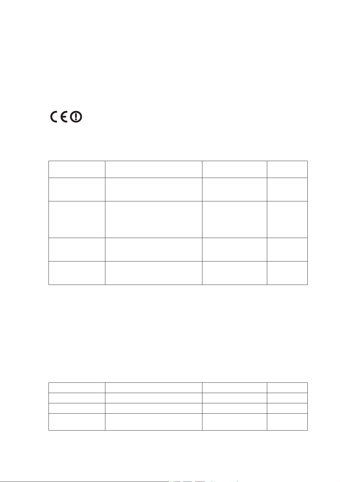
A terminal operating in the following frequency bands / channel sizes has been tested
and is compliant to the ETSI radio specifications and suitably displays the CE logo.
Other bands are compliant to the same radio performance specifications as adapted by
4RF and therefore may be used in regions where compliance requirements demand
CE performance at other frequencies.
Frequency band Channel size Power input Notified
body
300 MHz
400 MHz
25 kHz, 50 kHz, 75 kHz, 150 kHz,
250 kHz, 500 kHz, 1.0 MHz,
1.75 MHz, 3.50 MHz
12 VDC, 24 VDC,
48 VDC, 115/230 VAC
Notified
Body 0678
600 MHz
700 MHz
800 MHz
900 MHz
500 kHz 12 VDC, 24 VDC,
48 VDC, 115/230 VAC
Notified
Body 0678
1400 MHz 75 kHz, 150 kHz, 250 kHz,
500 kHz, 1.0 MHz, 1.75 MHz,
3.50 MHz
12 VDC, 24 VDC,
48 VDC, 115/230 VAC
2000 MHz
2500 MHz
250 kHz, 500 kHz, 1.0 MHz,
1.75 MHz, 3.50 MHz, 7 MHz,
14 MHz
12 VDC, 24 VDC,
48 VDC, 115/230 VAC
Compliance FCC
The terminal is designed to comply with the Federal Communications Commission (FCC)
specifications as follows:
Radio performance / EMC
(dependant on variant)
47CFR part 90 Private Land Mobile Radio Services
47CFR part 101 Fixed Microwave Services
47CFR part 15 Radio Frequency Devices
Safety EN 60950
Available in 1Q 2007
Frequency band Channel size Power input FCC ID
400 MHz 25 kHz 48 VDC
900 MHz 100 kHz 48 VDC
900 MHz 200 kHz 48 VDC Verified part
101

Informal declaration of conformity
Dansk
Undertegnede 4RF Communications Ltd erklærer herved, at følgende udstyr
Aprisa™ Radio overholder de væsentlige krav og øvrige relevante krav i
direktiv 1999/5/EF.
Deutsch
Hiermit erklärt 4RF Communications Ltd, dass sich dieses Aprisa™ Radio in
Übereinstimmung mit den grundlegenden Anforderungen und den anderen
relevanten Vorschriften der Richtlinie 1999/5/EG befindet. (BMWi)
Dutch
Hierbij verklaart 4RF Communications Ltd dat het toestel Aprisa™ Radio in
overeenstemming is met de essentiële eisen en de andere relevante
bepalingen van richtlijn 1999/5/EG.
English
Hereby, 4RF Communications Ltd, declares that this Aprisa™ Radio equipment
is in compliance with the essential requirements and other relevant provisions
of Directive 1999/5/EC.
Español
Por medio de la presente 4RF Communications Ltd declara que el Aprisa™
Radio cumple con los requisitos esenciales y cualesquiera otras disposiciones
aplicables o exigibles de la Directiva 1999/5/CE.
Σλληνας
4RF Communications Ltd Aprisa™ Radio
1995/5/.
Français
Par la présente 4RF Communications Ltd déclare que l'appareil Aprisa Radio
est conformé aux exigences essentielles et aux autres dispositions pertinentes
de la directive 1999/5/CE.
Italiano
Con la presente 4RF Communications Ltd dichiara che questo Aprisa™ Radio
è conforme ai requisiti essenziali ed alle altre disposizioni pertinenti stabilite
dalla direttiva 1999/5/CE.
Português
4RF Communications Ltd declara que este Aprisa™ Radio está conforme com
os requisitos essenciais e outras provisões da Directiva 1999/5/CE.
Suomalainen
4RF Communications Ltd vakuuttaa täten että Aprisa™ Radio tyyppinen laite
on direktiivin 1999/5/EY oleellisten vaatimusten ja sitä koskevien direktiivin
muiden ehtojen mukainen.
Svensk
Härmed intygar 4RF Communications Ltd att denna Aprisa™ Radio står I
överensstämmelse med de väsentliga egenskapskrav och övriga relevanta
bestämmelser som framgår av direktiv 1999/5/EG.
A formal Declaration of Conformity document is shipped with each Aprisa XE terminal.


Contents | v
Contents
1. Getting started ................................................................................................11
2. Introduction.....................................................................................................15
About this manual..........................................................................................................15
What it covers ......................................................................................................15
Who should read it ...............................................................................................15
Contact us............................................................................................................15
What's in the box...........................................................................................................15
Aprisa CD contents ..............................................................................................16
Accessory kit ........................................................................................................17
3. Preparation......................................................................................................19
Path planning ................................................................................................................19
Antenna selection and siting ................................................................................19
Coaxial feeder cables...........................................................................................22
Link budget...........................................................................................................22
Site requirements ..........................................................................................................23
Power supply........................................................................................................23
Equipment cooling................................................................................................23
Earthing and lightning protection..........................................................................24
4. About the terminal ..........................................................................................25
Introduction....................................................................................................................25
Modules.........................................................................................................................26
Front panel connections and indicators.........................................................................27
Interface card types.......................................................................................................28
5. Mounting and installing the terminal ............................................................29
Required tools ...............................................................................................................29
Installing the terminal ....................................................................................................29
Installing the antenna and feeder cable ........................................................................30
External alarms .............................................................................................................31
Alarm circuit setup................................................................................................31
Interface cabling ............................................................................................................32
Power supplies ..............................................................................................................32
DC power supply..................................................................................................32
AC power supply ..................................................................................................35
Safety earth..........................................................................................................36
Bench setup ..................................................................................................................37
6. Connecting to the terminal.............................................................................39
Connecting to the terminal's setup port.........................................................................39
Connecting to the terminal's ethernet interface.............................................................42
PC requirements for SuperVisor ..........................................................................43
PC settings for SuperVisor...................................................................................44
IP addressing of terminals.............................................................................................47
Network IP addressing ..................................................................................................48
Same subnet as local PC.....................................................................................48
Different subnet as local PC.................................................................................49

Contents | vi
7. Managing the terminal....................................................................................51
The setup menu ............................................................................................................51
4RF SuperVisor.............................................................................................................53
Logging in.............................................................................................................54
Logging out ..........................................................................................................54
SuperVisor opening page..............................................................................................55
Changing the terminal’s IP address ..............................................................................56
Setting up users ............................................................................................................57
User groups..........................................................................................................57
Adding a user .......................................................................................................57
Disabling a user ...................................................................................................58
Deleting a user.....................................................................................................58
Saving user information .......................................................................................58
Changing passwords............................................................................................59
Viewing user session details................................................................................59
8. Configuring the terminal ................................................................................61
Configuring the RF settings...........................................................................................61
Modem Performance Settings..............................................................................63
Entering terminal information ........................................................................................64
Configuring the IP settings ............................................................................................65
Saving the terminal's configuration................................................................................66
SNMP (Simple Network Management Protocol) ...........................................................67
SNMP access controls .........................................................................................68
SNMP trap destinations .......................................................................................69
Viewing the SNMP traps ......................................................................................70
Viewing the SNMP MIB details ............................................................................70
Setting the terminal clock sources.................................................................................71
Configuring the RSSI alarm threshold...........................................................................73
Configuring the external alarms ....................................................................................74
Configuring the external alarm inputs ..................................................................74
Configuring the external alarm outputs ................................................................76
9. Configuring the traffic interfaces ..................................................................77
Viewing a summary of the interfaces ............................................................................77
Configuring the traffic interfaces....................................................................................79
Ethernet.........................................................................................................................80
VLAN tagging .......................................................................................................80
Quality of Service .................................................................................................82
Viewing the status of the ethernet ports...............................................................86
Resetting the Ethernet settings............................................................................86
QJET port settings.........................................................................................................87
Q4EM port settings........................................................................................................89
DFXO / DFXS loop interface circuits .............................................................................91
DFXS port settings ...............................................................................................94
DFXO port settings.............................................................................................101
QV24 port settings.......................................................................................................108
HSS port settings ........................................................................................................109
HSS handshaking and clocking...................................................................................111
HSS handshaking and control line function .......................................................111
HSS synchronous clock selection modes ..........................................................114
10. Cross Connections ....................................................................................... 121
Embedded cross connect switch.................................................................................121
Link Capacity Utilization.....................................................................................121
The Cross Connections application.............................................................................121
The Cross Connections system requirements ...................................................121
Installing the Cross Connections application .....................................................122

Contents | vii
Opening the Cross Connections application ......................................................122
The Cross Connections page.............................................................................123
Setting the terminal's address............................................................................125
Management and user ethernet capacity...........................................................125
Setting card types ..............................................................................................126
Getting cross connection configuration from the terminals ................................126
Creating cross connections................................................................................127
Sending cross connection configuration to the terminals...................................130
Saving cross connection configurations.............................................................130
Using existing cross connection configurations .................................................130
Printing the cross connection configuration .......................................................131
Deleting cross connections ................................................................................132
Configuring the traffic cross connections ....................................................................133
Compatible interfaces ........................................................................................133
QJET cross connections ....................................................................................134
Selecting and mapping bits and timeslots..........................................................139
Q4EM cross connections ...................................................................................143
DFXS & DFXO cross connections .....................................................................144
QV24 cross connections ....................................................................................145
HSS cross connections ......................................................................................146
Cross connection example ..........................................................................................147
Symmetrical Connection Wizard .................................................................................148
Starting the wizard .............................................................................................148
Wizard Navigation ..............................................................................................148
Setting the IP address........................................................................................149
Setting the bandwidth.........................................................................................149
Card Selection....................................................................................................150
Interface configurations......................................................................................151
Symmetrical connection summary .....................................................................152
Send symmetrical connection configuration.......................................................152
11. Protected terminals ......................................................................................153
Monitored Hot Stand By (MHSB) ................................................................................153
Tributary switch front panel ................................................................................154
RF switch front panel .........................................................................................155
MHSB cabling ....................................................................................................157
MHSB power supply...........................................................................................157
Configuring the radios for protected mode.........................................................158
12. In-service commissioning............................................................................163
Before you start ...........................................................................................................163
What you will need .............................................................................................163
Applying power to the terminals ..................................................................................164
Review the link configurations using SuperVisor.........................................................164
Antenna alignment ......................................................................................................165
Checking the antenna polarization.....................................................................165
Visually aligning antennas..................................................................................166
Accurately aligning the antennas .......................................................................167
Synchronizing the terminals ...............................................................................169
Checking performance .......................................................................................169
Checking the receive input level ........................................................................169
Checking the fade margin ..................................................................................170
Checking long-term BER....................................................................................171
Bit Error Rate tests.............................................................................................171
Additional tests...................................................................................................172
Checking the link performance...........................................................................173
Viewing a summary of the link performance ......................................................174

Contents | viii
13. Maintenance ..................................................................................................175
Routine maintenance ..................................................................................................175
Terminal upgrades ......................................................................................................176
Upgrade process................................................................................................176
Installing RF synthesizer configuration files.......................................................176
Upgrading the terminal using TFTP ...................................................................177
Upgrading the terminal by uploading system files..............................................182
Viewing the image table .....................................................................................187
Changing the status of an image file..................................................................188
Rebooting the terminal ................................................................................................189
Support summary ........................................................................................................190
Installing interface cards..............................................................................................191
Preparing the terminal for new interface cards ..................................................192
Installing an interface card .................................................................................194
Configuring a slot ...............................................................................................196
14. Troubleshooting............................................................................................197
Loopbacks ...................................................................................................................197
RF radio loopback..............................................................................................197
Interface loopbacks............................................................................................198
Timeslot loopbacks ............................................................................................198
Alarms .........................................................................................................................199
Diagnosing alarms .............................................................................................199
Viewing the alarm history ...................................................................................201
Viewing interface alarms ....................................................................................202
Clearing alarms ..................................................................................................203
Identifying causes of alarms...............................................................................204
E1 / T1 alarm conditions ....................................................................................206
System log...................................................................................................................207
Checking the syslog...........................................................................................207
Setting up for remote logging .............................................................................209
15. Interface connections...................................................................................211
RJ-45 connector pin assignments ...............................................................................211
Interface traffic direction ..............................................................................................211
QJET Interface connections ........................................................................................212
Ethernet interface connections....................................................................................213
Q4EM Interface connections .......................................................................................214
E&M Signalling types .........................................................................................215
DFXS Interface connections........................................................................................217
DFXO Interface connections .......................................................................................218
HSS Interface connections..........................................................................................219
Synchronous cable assemblies..........................................................................220
Cable WAN connectors......................................................................................227
QV24 Interface connections ........................................................................................228
16. Alarm types and sources .............................................................................229
Alarm types .................................................................................................................229
Transmitter alarms .............................................................................................229
Receiver alarms .................................................................................................230
MUX alarms .......................................................................................................230
Modem alarms ...................................................................................................230
Motherboard alarms ...........................................................................................231
QJET alarms ......................................................................................................231
DFXO alarms .....................................................................................................232
DFXS alarms......................................................................................................232
HSS alarms ........................................................................................................232
QV24 alarms ......................................................................................................232

Contents | ix
External alarm inputs .........................................................................................233
Remote terminal alarms .....................................................................................233
Cross connect alarms ........................................................................................233
MHSB alarms .....................................................................................................233
17. Country specific settings .............................................................................235
18. Specifications................................................................................................237
RF specifications .........................................................................................................237
System performance specifications.............................................................................238
Interface specifications................................................................................................244
Ethernet interface...............................................................................................244
QJET Quad E1 / T1 interface.............................................................................244
Q4EM Quad 4 wire E&M interface .....................................................................245
DFXO Dual foreign exchange office interface....................................................246
DFXS Dual foreign exchange subscriber interface ............................................248
QV24 Quad V.24 asynchronous data interface..................................................250
HSS Single high speed synchronous data interface ..........................................250
External alarm interfaces ...................................................................................251
Auxiliary interfaces .............................................................................................251
Power specifications....................................................................................................252
AC Power supply................................................................................................252
DC Power supply ...............................................................................................252
Power consumption............................................................................................252
MHSB specifications ...................................................................................................253
MHSB protection ................................................................................................253
General specifications .................................................................................................253
Environmental ....................................................................................................253
Mechanical.........................................................................................................253
ETSI performance ..............................................................................................253
19. Product end of life ........................................................................................255
End-of-life recycling programme (WEEE)....................................................................255
The WEEE symbol explained.............................................................................255
WEEE must be collected separately ..................................................................255
Return and collection programmes in your area ................................................255
Your role in the recovery of WEEE ....................................................................255
EEE waste impacts the environment and health................................................255
20. Abbreviations ................................................................................................ 257
21. Acknowledgments and licensing ................................................................259
22. Commissioning Forms .................................................................................265
23. Index ..............................................................................................................267


Getting started | 11
1. Getting started
This section is an overview of the steps required to commission a link in the field.
Phase 1: Pre-installation
1. Confirm path planning. Page
19
2. Ensure that the site preparation is complete:
Power requirements
Tower requirements
Environmental considerations, for example, temperature control
Rack space
Page
22
3. Confirm the interface card configuration.
Phase 2: Installing the terminals
1. Before installing the terminal into the rack, check that all the required
interface cards are fitted.
Position and mount the terminal in the rack. Page
29
2. Connect earthing to the terminal. Page
24
3. Confirm that the:
Antenna is mounted and visually aligned.
Feeder cable is connected to the antenna.
Feeder connections are tightened to recommended level.
Tower earthing is complete.
4. Install lightning protection. Page
24
5. Connect the coaxial jumper cable between the lightning protection and the
terminal duplexer.
6. Connect the power supply to the terminal and apply power. Page
31

Getting started | 12
Phase 3: Establishing the link
1. If you don't know the terminal's IP address :
Connect the setup cable between the terminal's Setup port and the PC
using accessory kit adaptor.
Use HyperTerminal to confirm the IP settings for the terminal:
Local IP address
Local subnet mask
Remote terminal IP address
Reboot the terminal
Page
52
2. Connect the Ethernet cable between the terminal's 4-port Ethernet switch
and the PC.
3. Confirm that the PC IP settings are correct for the 4-port Ethernet switch:
IP address
subnet mask
Page
44
4. Confirm that Java is installed on the PC. Page
43
5. Start the web browser, and log into the terminal. Page
54
6. Set or confirm the RF characteristics:
TX and RX frequencies
Modulation type
TX output power
Page
61
7. Compare the actual RSSI to the expected RSSI value (from your path
planning).
8. Fine-align the antennas. Page
167
9. Confirm that the terminal clock sources are set correctly. Page
63
10. Confirm that the TX and RX LEDs are green. Disregard the OK LED
status for now.

Getting started | 13
Phase 4: Configuring the traffic
1. Confirm that the interface hardware and software slot configurations
match.
2. Confirm the interface card settings. Page
79
3. Open the Cross Connections application and configure the cross
connections:
Download the configuration.
Confirm or modify the traffic cross connections.
Save the configuration to the terminal.
Activate the configuration.
Page
122
4. Save the configuration to disk and close the Cross Connections
application.
Page
130
5. Connect the connection of interface cables.
6. Confirm or adjust the terminal clocking for network synchronization, if
required.
7. Test that the traffic is passing over the link as configured.
8. Confirm or configure the external alarm settings in SuperVisor. Page
74
9. Setup an external alarm connection cable, if required.
10. Reset any alarms and error counters. Page
199
11. Perform traffic pre-commissioning tests (optional)
12. Complete the commissioning form (at the back of the manual) and file. Page
265


Introduction | 15
2. Introduction
About this manual
What it covers
This user manual describes how to install and configure Aprisa XE™ fixed point-to-point digital radio
links.
It specifically documents an Aprisa XE terminal running system software version 7.3.1.
It is recommended that you read the relevant sections of this manual before installing or operating the
terminal.
Who should read it
This manual has been written for professional field technicians and engineers who have an
appropriate level of education and experience.
Contact us
If you experience any difficulty installing or using Aprisa XE after reading this manual, please contact
Customer Support or your local 4RF representative.
Our area representative contact details are available from our website:
4RF Communications Ltd
26 Glover Street, Ngauranga
PO Box 13-506
Wellington 6032
New Zealand
E-mail
support@4rf.com
Web site
www.4rf.com
Telephone +64 4 499 6000
Facsimile +64 4 473 4447
Attention Customer Services
What's in the box
Inside the box you will find:
Aprisa XE terminal
Accessory kit
Aprisa CD
Aprisa XE Quick Start Guide
Commissioning Form
Configuration sheet

Introduction | 16
Aprisa CD contents
The Aprisa CD contains the following:
Software
The latest version of the terminal software (see "Terminal upgrades” on page 176)
The Cross Connections application - required if you want to use the Cross Connections
application offline (see "
Installing Cross Connections application" on page 122).
Java VM - Java plug-in needed to run the Supervisor software.
Web browsers - Mozilla Firefox and Internet Explorer are included for your convenience.
Adobe™ Acrobat® Reader® which you need to view the PDF files on the Aprisa CD.
Documentation
User manual — an electronic (PDF) version for you to view online or print.
Product collateral — application overviews, product description, case studies, and white
papers.
Tools
Surveyor - a path propagation calculator developed by 4RF (see "Path planning" on page 19).

Introduction | 17
Accessory kit
The accessory kit contains the following items:
Setup cable (RJ-45) and adaptor
Mounting brackets and screws
Hardware kit
(includes Allen key for fascia
screws)
Alarm cable (RJ-45)

Introduction | 18
Ground cable
DC power cable
(for use with the -48 VDC and -24
VDC power supplies)
AC power cable
(for use with the 110 / 230 VAC
power supply)
Preparation | 19
3. Preparation
Path planning
Proper path planning is essential. When considering the components of your radio system, think
about:
antenna selection and siting
coaxial cable selection
link budget
You can also use Surveyor to help you with path feasibility planning.
Surveyor is a path propagation calculator developed by 4RF to assist path planners quickly and
efficiently verify the viability of point-to-point transmission links deploying the Aprisa™ microwave radio
systems.
The software program calculates the anticipated link performance for the transmission system
elements you have selected. However, it is not a substitute for in-depth path planning.
You will find Surveyor a valuable addition to your planning toolbox.
A copy of Surveyor is provided on the Aprisa CD supplied with this manual. You can download
updates from
www.4rf.com.
Antenna selection and siting
Selecting and siting antennas are important considerations in your system design.
There are three main types of directional antenna that are commonly used with the radios parabolic
grid, Yagi and corner reflector antennas.
The antenna that should be used for a particular situation is determined primarily by the frequency of
operation and the gain required to establish a reliable link.
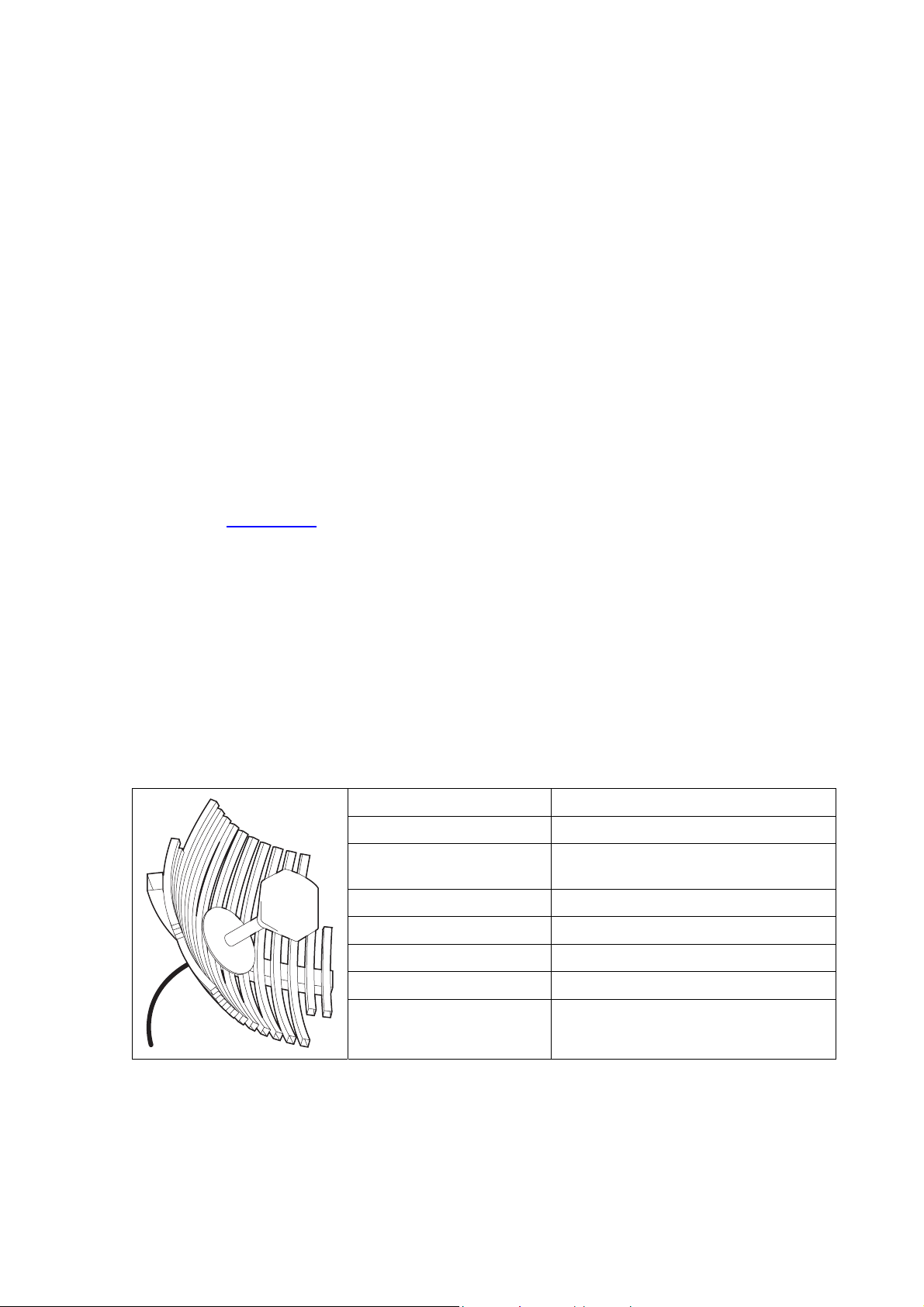
Parabolic grid antennas
Factor Explanation
Frequency Often used in 1350-2700 MHz bands
Gain Varies with size (17 dBi to 30 dBi
typical)
Wind loading Can be significant
Tower aperture required Can be significant
Size Range from 0.6 m to 3 m diameter
Front to back ratio Good
Cost High

Preparation | 20
Yagi antennas
Factor Explanation
Frequency Often used in 330-960 MHz bands
Gain Varies with size (typically 11 dBi to 16
dBi)
Stackable gain increase 2 Yagi antennas (+ 2.8 dB)
4 Yagi antennas (+ 5.6 dB)
Wind loading Less than a parabolic grid antenna
Tower aperture required Unstacked: Less than a parabolic grid
antenna
Stacked: about the same as a
parabolic grid antenna
Size Range from 0.6 m to 3 m in length
Front to back ratio Low
Cost Low
It is possible to increase the gain of a Yagi antenna installation by placing two or more of them in a
stack. The relative position of the antennas is critical.
Example of stacked antennas

Preparation | 21
Corner reflector antennas
Factor Explanation
Frequency Often used in 330-960 MHz bands
Gain Typically 10 dBd
Wind loading Less than a parabolic grid antenna
Tower aperture required About the same as a parabolic grid
antenna
Size Range from 0.36 m to 0.75 m in length
Front to back ratio High (typically 30 dB)
Beamwidth Broad (up to 60°)
Cost Medium
Antenna siting
When siting antennas, consider the following points:
A site with a clear line of sight to the remote terminal is needed. Pay particular attention to trees,
buildings, and other obstructions close to the antenna site.
Example of a clear line-of-sight path
Any large flat areas that reflect RF energy along the link path, for instance, water, could cause
multi-path fading. If the link path crosses a feature that is likely to cause RF reflections, shield the
antenna from the reflected signals by positioning it on the far side of the roof of the equipment
shelter or other structure.
Example of a mid-path reflection path
The antenna site should be as far as possible from other potential sources of RF interference such
as electrical equipment, power lines and roads.
The antenna site should be as close as possible to the equipment shelter.
Note: Wide angle and zoom photographs taken at the proposed antenna location (looking down the
proposed path), can be useful when considering the best mounting positions.

Preparation | 22
Coaxial feeder cables
To ensure maximum performance, it is recommended that you use good quality low-loss coaxial cable
for all feeder runs. For installations requiring long antenna cable runs, use Andrew Heliax™ or
equivalent.
When using large diameter feeders, use a short flexible jumper cable between the feeder and the
terminal to reduce stress on the antenna port connector.
All coaxial cable has loss, that is, the RF energy traveling through it is attenuated. Generally speaking,
the larger the diameter of the cable, the less the loss. When selecting a coaxial cable consider the
following:
Factor Effect
Attenuation Short cables and larger diameter cables have less attenuation
Cost Smaller diameter cables are cheaper
Ease of installation Easier with smaller diameter cables or short cables
When running cables:
Run coaxial cable from the installation to the antenna, ensuring you leave enough extra cable at
each end to allow drip loops to be formed.
For 19-inch rack mount installations, cables may be run from the front of the rack directly onto the
antenna port. They may also be run through the back of the rack to the front.
Terminate and earth or ground the cables in accordance with the manufacturers' instructions.
Bond the outer conductor of the coaxial feeder cables to the base of the tower mast.
Link budget
All of the above factors (and many others not mentioned) combine in any proposed installation to
create a link budget. The link budget predicts how well the radio link will perform after it is installed.
Use the outputs of the link budget during commissioning testing to confirm the link has been installed
correctly, and that it will provide reliable service.

Preparation | 23
Site requirements
Power supply
Ensure that the correct power supply is available for powering the terminal.
The nominal input voltage for a terminal is 12, 24 or 48 volts DC or 115 / 230 volts AC rms.
The DC supply voltage is factory preset at time of order and cannot be adjusted in the field.
The terminal voltage is indicated on the chassis label by the DC input connector and on the
specification label fitted to the terminal.
Warning:
Before connecting power, ground the chassis using the safety earth terminal on the
front panel.
Equipment cooling
Mount the terminal so that air can flow through it. Do not obstruct the free flow of air around the
terminal. The two internal, speed-controlled fans fitted into the chassis provide sufficient cooling.
The fans are microprocessor-controlled to run at the minimum speed required to keep the terminal
below a preset temperature. They are constantly monitored and an alarm is raised under failure
conditions.
The environmental operating conditions are as follows:
Operating temperature -10°C to +50°C
Storage temperature -20°C to +70°C
Humidity Maximum 95% non-condensing
Altitude Up to 5000 metres

Preparation | 24
Earthing and lightning protection
Warning:
Lightning can easily damage electronic equipment.
To avoid this risk, install primary lightning protection devices on any interfaces that are
reticulated in the local cable network.
You should also install a coaxial surge suppressor on the antenna port of the duplexer
Earth the antenna tower, feeders and lightning protection devices in accordance with the appropriate
local and national standards. The diagram below shows the minimum requirements.
Use grounding kits as specified or supplied by the coaxial cable manufacturer to properly ground or
bond the cable outer.

About the terminal | 25
4. About the terminal
Introduction
The terminals operate in a number of frequency bands from 300 MHz up to 2.7 GHz carrying ethernet,
voice and data traffic over distances up to 100 kilometres.
They are designed to meet the demands of a wide range of low to medium capacity access and
backhaul applications.
The digital access terminal is a compact, powerful point-to-point linking solution with up to 64 Mbit/s of
radio link capacity, and customer-configurable interface options integrated within the radio platform.

About the terminal | 26
Modules
The terminal is modular in design, which helps reduce mean time to repair (MTTR). It is designed for
19-inch rack mounting and is only 2U high for standard configurations.
The five main modules housed inside the chassis are the transceiver, modem, motherboard, power
supply, and duplexer. Interface cards are fitted into the eight interface slots on the motherboard.
Modules are interconnected via several buses on the motherboard. A duplexer can be mounted inside
or outside the chassis.
The interrelationships between the components are shown below:

About the terminal | 27
Front panel connections and indicators
All connections to the terminal are made on the front panel of the terminal.
No. Label Description
1 AC or DC power input DC and AC power supplies are available (AC is shown)
2 Safety earth stud An M5 stud for connection to an external protection ground for
protection against electric shock in case of a fault.
3 Antenna connector N-type 50 female connector for connection of antenna feeder
cable.
4 Interface slots A to H Eight interface slots on the motherboard to fit interface cards.
5 ETHERNET Integrated four-port layer 2 switch.
6 SETUP RJ-45 serial connection to PC for initial configuration.
7 ALARM RJ-45 connector for two external alarm input and four external
alarm output connections.
8 LED indicators
OK Indicates normal operation and minor and major alarm
conditions.
RX Indicates status of receive path including normal operation and
alarms such as BER, RSSI and loss of synchronization.
TX Indicates status of transmit path including normal operation and
alarms such as forward / reverse power and temperature.
ON Blue LED indicates that there is power to the terminal.
9 RSSI RSSI test point suitable for 2 mm diameter multimeter test lead
pin.

About the terminal | 28
Interface card types
Each terminal has eight interface slots labeled A to H. Each slot can be fitted with any interface card
type. Typically, the terminal is delivered pre-configured with the requested interface cards.
The following interface card types are currently available:
Name Interface card type Function
QJET Quad E1/T1 interface card Four E1 / T1 interfaces (Framed or Unframed).
Q4EM Quad 4 wire E&M interface card Four 4 wire E&M voice channels
DFXS Dual 2 wire FXS interface card Two 2 wire loop signalling foreign exchange
subscriber (POTS) channels
DFXO Dual 2 wire FXO interface card Two 2 wire loop signalling foreign exchange office
channels
HSS High-Speed Synchronous
interface card
A single high speed serial data channel configured
as synchronous V.24, V.35, X.21, V.36 / RS 449,
or EIA/TIA 530.
QV24 Quad V.24 serial asynchronous
interface card
Four asynchronous V.24/RS232 data channels.

Mounting and installing the terminal | 29
5. Mounting and installing the terminal
This section covers installing the hardware associated with the terminal. Before you begin a terminal
installation, read this section thoroughly.
Warning:
You must comply with the safety precautions in this manual or on the product
itself. 4RF does not assume any liability for failure to comply with these
precautions.
Required tools
No special tools are needed to install the terminal other than those required to physically mount the
terminal into the rack.
Installing the terminal
The terminal is designed for 19-inch rack mounting and is supplied with rack mounting brackets. The
rack brackets can be front, mid, or rear mounted (as shown below) to suit individual installation
requirements. Once the rack brackets are attached, carefully lift the terminal into position in the rack,
and fasten with screws and washers.
 Loading...