

April 2012
Version 8.6.77


| 1
Aprisa XE User Manual
Copyright
Copyright © 2012 4RF Limited. All rights reserved.
This document is protected by copyright belonging to 4RF Limited and may not be reproduced or
republished in whole or part in any form without the prior written permission of 4RF Limited.
Trademarks
Aprisa and the 4RF logo are trademarks of 4RF Limited.
Windows is a registered trademark of Microsoft Corporation in the United States and other countries. Java
and all Java-related trademarks are trademarks or registered trademarks of Sun Microsystems, Inc. in the
United States and other countries. All other marks are the property of their respective owners.
GoAhead WebServer. Copyright © 2000 GoAhead Software, Inc. All Rights Reserved.
Disclaimer
Although every precaution has been taken preparing this information, 4RF Limited assumes no liability for
errors and omissions, or any damages resulting from use of this information. This document or the
equipment may change, without notice, in the interests of improving the product.
RoHS and WEEE Compliance
The Aprisa XE is fully compliant with the European Commission’s RoHS (Restriction of Certain Hazardous
Substances in Electrical and Electronic Equipment) and WEEE (Waste Electrical and Electronic Equipment)
environmental directives.
Restriction of hazardous substances (RoHS)
The RoHS Directive prohibits the sale in the European Union of electronic equipment containing these
hazardous substances: lead*, cadmium, mercury, hexavalent chromium, polybrominated biphenyls (PBBs),
and polybrominated diphenyl ethers (PBDEs).
4RF Limited has worked with its component suppliers to ensure compliance with the RoHS Directive which
came into effect on the 1st July 2006.
*The European Commission Technical Adaptation Committee (TAC) has exempted lead in solder for highreliability applications for which viable lead-free alternatives have not yet been identified. The exemption
covers communications network infrastructure equipment, which includes 4RF Limited Aprisa XE
microwave radios.
End-of-life recycling programme (WEEE)
The WEEE Directive concerns the recovery, reuse, and recycling of electronic and electrical equipment.
Under the Directive, used equipment must be marked, collected separately, and disposed of properly.
4RF Limited has instigated a programme to manage the reuse, recycling, and recovery of waste in an
environmentally safe manner using processes that comply with the WEEE Directive (EU Waste Electrical
and Electronic Equipment 2002/96/EC).
4RF Limited invites questions from customers and partners on its environmental programmes and
compliance with the European Commission’s Directives (sales@4RF.com).
2 |
Aprisa XE User Manual
Radio performance
EN 302 217 Parts 1, 2.1, and 2.2
EMC
EN 301 489 Parts 1 & 4
Environmental
EN 300 019, Class 3.2
Safety
EN 60950
An Aprisa XE radio terminal operating in the following frequency bands / channel sizes
has been tested and is compliant to the ETSI radio specifications and suitably displays
the CE logo.
Other bands are compliant to the same radio performance specifications as adapted by
4RF Limited and therefore may be used in regions where compliance requirements
demand CE performance at other frequencies.
Frequency band
Channel size
Power input
Notified
body
300 MHz
400 MHz
25 kHz, 50 kHz, 75 kHz, 125 kHz,
150 kHz, 250 kHz, 500 kHz,
1.0 MHz, 1.75 MHz, 3.50 MHz
12 VDC, 24 VDC,
48 VDC, 115/230 VAC
Notified
Body 0678
600 MHz
700 MHz
800 MHz
900 MHz
500 kHz
12 VDC, 24 VDC,
48 VDC, 115/230 VAC
Notified
Body 0678
1400 MHz
75 kHz, 150 kHz, 250 kHz,
500 kHz, 1.0 MHz, 1.75 MHz,
3.50 MHz, 7 MHz
12 VDC, 12 VDC LP,
24 VDC, 48 VDC,
115/230 VAC
1800 MHz
2000 MHz
2500 MHz
250 kHz, 500 kHz, 1.0 MHz,
1.75 MHz, 3.50 MHz, 7 MHz,
14 MHz
12 VDC, 24 VDC,
48 VDC, 115/230 VAC
Compliance General
The Aprisa XE digital radio predominantly operates within frequency bands that require a site license be
issued by the radio regulatory authority with jurisdiction over the territory in which the equipment is
being operated.
It is the responsibility of the user, before operating the equipment, to ensure that where required the
appropriate license has been granted and all conditions attendant to that license have been met.
Changes or modifications not approved by the party responsible for compliance could void the user’s
authority to operate the equipment.
Equipment authorizations sought by 4RF Limited are based on the Aprisa XE radio equipment being
installed at a fixed location and operated in a continuous point-to-point mode within the environmental
profile defined by EN 300 019, Class 3.2. Operation outside these criteria may invalidate the
authorizations and / or license conditions.
The term ‘Terminal’ with reference to the Aprisa XE User Manual, is a generic term for one end of a fixed
point-to-point Aprisa XE link and does not confer any rights to connect to any public network or to operate
the equipment within any territory.
Compliance ETSI
The Aprisa XE radio terminal is designed to comply with the European Telecommunications Standards
Institute (ETSI) specifications as follows:

| 3
Aprisa XE User Manual
Dansk
Undertegnede 4RF Limited erklærer herved, at følgende udstyr Aprisa Radio
overholder de væsentlige krav og øvrige relevante krav i direktiv 1999/5/EF.
Deutsch
Hiermit erklärt 4RF Limited, dass sich dieses Aprisa Radio in Übereinstimmung
mit den grundlegenden Anforderungen und den anderen relevanten
Vorschriften der Richtlinie 1999/5/EG befindet. (BMWi)
Dutch
Hierbij verklaart 4RF Limited dat het toestel Aprisa Radio in
overeenstemming is met de essentiële eisen en de andere relevante
bepalingen van richtlijn 1999/5/EG.
English
Hereby, 4RF Limited, declares that this Aprisa Radio equipment is in
compliance with the essential requirements and other relevant provisions of
Directive 1999/5/EC.
Español
Por medio de la presente 4RF Limited declara que el Aprisa Radio cumple con
los requisitos esenciales y cualesquiera otras disposiciones aplicables o
exigibles de la Directiva 1999/5/CE.
λληνας
ΜΕ ΣΗΝ ΠΑΡΟΤΑ 4RF Limited ΔΗΛΩΝΕΙ ΟΣΙ Aprisa Radio ΤΜΜΟΡΥΩΝΣΑΙ
ΠΡΟ ΣΙ ΟΤΙΩΔΕΙ ΑΠΑΙΣΗΕΙ ΚΑΙ ΣΙ ΔΟΙΠΕ ΦΕΣΙΚΕ ΔΙΑΣΑΞΕΙ ΣΗ
ΟΣΗΓΙΑ 1995/5/ΚΕ.
Français
Par la présente 4RF Limited déclare que l'appareil Aprisa Radio est conformé
aux exigences essentielles et aux autres dispositions pertinentes de la
directive 1999/5/CE.
Italiano
Con la presente 4RF Limited dichiara che questo Aprisa Radio è conforme ai
requisiti essenziali ed alle altre disposizioni pertinenti stabilite dalla direttiva
1999/5/CE.
Português
4RF Limited declara que este Aprisa Radio está conforme com os requisitos
essenciais e outras provisões da Directiva 1999/5/CE.
Suomalainen
4RF Limited vakuuttaa täten että Aprisa Radio tyyppinen laite on direktiivin
1999/5/EY oleellisten vaatimusten ja sitä koskevien direktiivin muiden
ehtojen mukainen.
Svensk
Härmed intygar 4RF Limited att denna Aprisa Radio står I överensstämmelse
med de väsentliga egenskapskrav och övriga relevanta bestämmelser som
framgår av direktiv 1999/5/EG.
Informal Declaration of Conformity
A formal Declaration of Conformity document is shipped with each Aprisa XE terminal.

4 |
Aprisa XE User Manual
Radio performance / EMC
(dependant on variant)
47CFR part 90 Private Land Mobile Radio Services
47CFR part 101 Fixed Microwave Services
47CFR part 27 Misc Wireless Communication Services
47CFR part 15 Radio Frequency Devices
Safety
EN 60950
Frequency band
limits
Channel
size
Power input
Authorization
FCC ID
421 MHz to
512 MHz
25 kHz
48 VDC
Part 90 Certification
UIPN0400025A0200A
932.5 MHz to
944 MHz
100 kHz,
200 kHz
24 VDC,
48 VDC,
110 VAC
Part 101 Verification
-
2314.5 MHz to
2317.5 MHz
2346.5 MHz to
2349.5 MHz
250 kHz,
500 kHz
24 VDC,
48 VDC,
110 VAC
Part 27 Certification
UIPN2500AAAA0200A
Radio performance
(dependant on variant)
RSS-GEN
RSS-119
EMC
This Class A digital apparatus complies with Canadian
standard ICES-003
Safety
EN 60950
Frequency band
limits
Channel
size
Power input
Authorization
IC ID
932.5 MHz to
944 MHz
100 kHz,
200 kHz
24 VDC,
48 VDC,
110 VAC
RSS-119
6772A-N09AAACC
406.1 MHz to
430 MHz
450 MHz to
470 MHz
25 kHz,
75 kHz,
150 kHz
12 VDC
24 VDC,
48 VDC,
110 VAC
RSS-119
6772A-N04AAAEC
Compliance FCC
The Aprisa XE radio terminal is designed to comply with the Federal Communications Commission (FCC)
specifications as follows:
NOTE: This equipment has been tested and found to comply with the limits for a Class A digital device,
pursuant to part 15 of the FCC Rules. These limits are designed to provide reasonable protection against
harmful interference when the equipment is operated in a commercial environment. This equipment
generates, uses, and can radiate radio frequency energy and, if not installed and used in accordance with
the instruction manual, may cause harmful interference to radio communications. Operation of this
equipment in a residential area is likely to cause harmful interference in which case the user will be
required to correct the interference at his own expense.
Compliance Industry Canada
The Aprisa XE radio terminal is designed to comply with Industry Canada (IC) specifications as follows:

| 5
Aprisa XE User Manual
WARNING:
The installer and / or user of Aprisa XE radio terminals shall ensure that a separation
distance as given in the following table is maintained between the main axis of the
terminal’s antenna and the body of the user or nearby persons.
Minimum separation distances given are based on the maximum values of the
following methodologies:
1. Maximum Permissible Exposure non-occupational limit (B or general public) of
47 CFR 1.1310 and the methodology of FCC’s OST/OET Bulletin number 65.
2. Reference levels as given in Annex III, European Directive on the limitation of
exposure of the general public to electromagnetic fields (0 Hz to 300 GHz)
(1999/519/EC). These distances will ensure indirect compliance with the
requirements of EN 50385:2002.
Frequency
(MHz)
Maximum power
(dBm)
Maximum
antenna gain
(dBi)
Maximum power
density
(mW/cm2)
Minimum
separation
distance
(m)
400
+ 35
15
0.20
2.0
512
+ 35
15
0.26
1.8
715
+ 34
15
0.36
1.3
806
+ 34
28
0.40
5.6
890
+ 34
28
0.45
5.3
960
+ 34
28
0.48
5.1
1550
+ 34
33
0.78
7.2
2300
+ 34
37
1.00
10.0
2700
+ 34
38
1.00
11.2
RF Exposure Warning


Contents | 7
Aprisa XE User Manual
Contents
1. Getting Started .......................................................................... 15
2. Introduction .............................................................................. 19
About This Manual ............................................................................... 19
What It Covers ............................................................................ 19
Who Should Read It ...................................................................... 19
Contact Us ................................................................................. 19
What's in the Box ................................................................................ 19
Aprisa XE CD Contents ................................................................... 20
Accessory Kit .............................................................................. 21
3. Preparation............................................................................... 23
Path Planning .................................................................................... 23
Antenna Selection and Siting ........................................................... 23
Coaxial Feeder Cables ................................................................... 26
Link Budget ................................................................................ 26
Site Requirements ............................................................................... 27
Power Supply .............................................................................. 27
Equipment Cooling ....................................................................... 27
Earthing and Lightning Protection ..................................................... 28
4. About the Terminal..................................................................... 29
Introduction ...................................................................................... 29
Modules ........................................................................................... 30
Front Panel Connections and Indicators ..................................................... 31
Interface Card Types............................................................................ 32
5. Mounting and Installing the Terminal .............................................. 33
Required Tools ................................................................................... 33
Installing the Terminal ......................................................................... 33
Installing the Antenna and Feeder Cable .................................................... 34
External Alarms .................................................................................. 35
Alarm Circuit Setup ...................................................................... 35
Interface Cabling ................................................................................ 36
Power Supplies................................................................................... 37
DC Power Supply.......................................................................... 37
AC Power Supply .......................................................................... 40
Safety Earth ............................................................................... 42
Bench Setup ...................................................................................... 43

8 | Contents
Aprisa XE User Manual
6. Connecting to the Terminal .......................................................... 45
Connecting to the Terminal's Setup Port .................................................... 45
Connecting to the Terminal's Ethernet Interface ........................................... 48
PC Requirements for SuperVisor ....................................................... 49
PC Settings for SuperVisor .............................................................. 50
IP Addressing of Terminals ..................................................................... 53
Network IP Addressing .......................................................................... 54
Same Subnet as the Local PC ........................................................... 54
Different Subnet as the Local PC ...................................................... 55
7. Managing the Terminal ................................................................ 57
The Setup Menu ................................................................................. 57
SuperVisor ........................................................................................ 59
SuperVisor Logging In .................................................................... 60
SuperVisor Logging Out .................................................................. 61
SuperVisor Main Screen ......................................................................... 62
Changing the Terminal’s IP Address .......................................................... 64
Setting Up Users ................................................................................. 65
User groups ................................................................................ 65
Adding a User ............................................................................. 65
Disabling a User........................................................................... 66
Deleting a User ........................................................................... 66
Saving User Information ................................................................. 66
Changing Passwords ...................................................................... 67
Viewing User Session Details ............................................................ 67
8. Configuring the Terminal ............................................................. 69
Configuring the RF Settings .................................................................... 69
Modem Performance Settings........................................................... 72
Entering Basic Terminal Information ......................................................... 74
Configuring the IP Settings ..................................................................... 75
Setting the Terminal Clocking ................................................................. 76
Setting the Duplexer Parameters ............................................................. 79
Setting the RSSI Alarm Threshold ............................................................. 80
Configuring the External Alarms .............................................................. 81
Configuring the External Alarm Inputs ................................................ 81
Configuring the External Alarm Outputs .............................................. 83
Configuring SNMP Settings ..................................................................... 85
SNMP Access Controls .................................................................... 86
SNMP Trap Destinations ................................................................. 87
Viewing the SNMP Traps ................................................................. 88
Viewing the SNMP MIB Details .......................................................... 88
Saving the Terminal's Configuration .......................................................... 89

Contents | 9
Aprisa XE User Manual
9. Configuring the Traffic Interfaces .................................................. 91
Viewing a Summary of the Interfaces ........................................................ 91
Configuring the Traffic Interfaces ............................................................ 92
Ethernet Switch ................................................................................. 93
VLAN tagging .............................................................................. 93
Quality of Service ........................................................................ 96
Viewing the Status of the Ethernet Ports ........................................... 100
Resetting the Ethernet Settings ...................................................... 100
Ethernet Port Startup .................................................................. 101
QJET Port Settings ............................................................................ 102
Q4EM Port Settings ............................................................................ 104
Loop Interface Circuits ....................................................................... 107
DFXO / DFXS Loop Interface Circuits ................................................ 107
E1 CAS to DFXS Circuits ................................................................ 110
DFXS to DFXS Hotline Circuits ........................................................ 110
DFXS Port Settings ...................................................................... 112
DFXO Port Settings ..................................................................... 120
QV24 Serial Interface Card ................................................................... 128
QV24 Port Settings ..................................................................... 129
QV24S Port Settings .................................................................... 130
HSS Port Settings .............................................................................. 133
HSS Handshaking and Clocking Modes ...................................................... 135
HSS Handshaking and Control Line Function ....................................... 135
HSS Synchronous Clock Selection Modes ............................................ 138

10 | Contents
Aprisa XE User Manual
10. Cross Connections ..................................................................... 145
Embedded Cross Connect Switch............................................................ 145
Link Capacity Utilization .............................................................. 145
The Cross Connections Application ......................................................... 145
The Cross Connections System Requirements ...................................... 145
Installing the Cross Connections Application ....................................... 146
Opening the Cross Connections Application ........................................ 146
The Cross Connections Page .......................................................... 147
Setting the Terminal's IP Address .................................................... 149
Management and User Ethernet Capacity........................................... 150
Setting Card Types ..................................................................... 151
Getting Cross Connection Configuration from the Terminals .................... 151
Creating Cross Connections ........................................................... 152
Sending Cross Connection Configuration to the Terminals ....................... 155
Saving Cross Connection Configurations ............................................ 155
Using Existing Cross Connection Configurations ................................... 155
Printing the Cross Connection Configuration ....................................... 156
Deleting Cross Connections ........................................................... 157
Configuring the Traffic Cross Connections ................................................. 158
Compatible Interfaces ................................................................. 158
QJET Cross Connections ............................................................... 159
Selecting and Mapping Bits and Timeslots .......................................... 166
Q4EM Cross Connections ............................................................... 170
DFXS and DFXO Cross Connections ................................................... 171
QV24 Cross Connections ............................................................... 172
QV24S Cross Connections .............................................................. 173
HSS Cross Connections ................................................................. 174
Cross Connection Example ................................................................... 175
Symmetrical Connection Wizard ............................................................ 176
Starting the Cross Connections Wizard .............................................. 176
Cross Connections Wizard Navigation ............................................... 176
Setting the Cross Connections IP Address ........................................... 177
Setting the Cross Connections Bandwidth .......................................... 177
Cross Connections Card Selection .................................................... 178
Cross Connections Interface Configurations ........................................ 179
Symmetrical Connection Summary................................................... 180
Send Symmetrical Connection Configuration ....................................... 180
11. Protected Terminals .................................................................. 181
Monitored Hot Stand By (MHSB) ............................................................. 181
Tributary Switch Front Panel ......................................................... 182
RF Switch Front Panel ................................................................. 183
MHSB Cabling............................................................................ 185
MHSB Power Supply .................................................................... 185
Configuring the Radios for Protected Mode ........................................ 186
Hitless Space Diversity (HSD) ................................................................ 190
HSD Terminal Cabling .................................................................. 191
HSD Terminal IP Addresses ............................................................ 192

Contents | 11
Aprisa XE User Manual
12. In-Service Commissioning ............................................................ 197
Before You Start ............................................................................... 197
What You Will Need .................................................................... 197
Applying Power to the Terminals ........................................................... 198
Review the Link Configurations Using SuperVisor ........................................ 198
Antenna Alignment ............................................................................ 199
Checking the Antenna Polarization .................................................. 199
Visually Aligning Antennas ............................................................ 200
Accurately Aligning the Antennas .................................................... 201
Checking Performance ................................................................. 203
Checking the Receive Input Level .................................................... 203
Checking the Fade Margin ............................................................. 204
Checking the Long-Term BER ......................................................... 205
Bit Error Rate Tests .................................................................... 205
Additional Tests ........................................................................ 206
Checking the Link Performance ...................................................... 207
Viewing a Summary of the Link Performance ...................................... 208
Saving the History of the Link Performance ........................................ 209
13. Maintenance ............................................................................ 213
Routine Maintenance ......................................................................... 213
Terminal Upgrades ............................................................................ 214
Software Upgrade Process ............................................................ 215
Uploading the Root File System ...................................................... 216
Uploading the Motherboard Images .................................................. 216
Identifying the Correct TFTP Upgrade Type ........................................ 217
TFTP Upgrade Process Types ......................................................... 220
Uploading System Files ................................................................ 226
Viewing the Image Table .............................................................. 231
Changing the Status of an Image File................................................ 232
Rebooting the Terminal ...................................................................... 233
Support Summary.............................................................................. 234
Installing Interface Cards .................................................................... 235
Preparing the Terminal for New Interface Cards .................................. 236
Installing an Interface Card ........................................................... 238
Configuring a Slot ...................................................................... 240
14. Troubleshooting ........................................................................ 241
Loopbacks ...................................................................................... 241
RF Radio Loopback ..................................................................... 241
Interface Loopbacks ................................................................... 242
Timeslot Loopbacks .................................................................... 243
Alarms........................................................................................... 244
Diagnosing Alarms ...................................................................... 244
Viewing the Alarm History ............................................................ 246
Saving the Alarm History .............................................................. 247
Viewing Interface Alarms.............................................................. 248
Clearing Alarms ......................................................................... 249
Identifying Causes of Alarms .......................................................... 250
E1 / T1 Alarm Conditions.............................................................. 252
System Log ..................................................................................... 253
Checking the Syslog .................................................................... 253
Setting up for Remote Logging ....................................................... 255

12 | Contents
Aprisa XE User Manual
15. Interface Connections ................................................................ 257
RJ-45 Connector Pin Assignments ........................................................... 257
Interface Traffic Direction ................................................................... 257
QJET Interface Connections ................................................................. 258
Ethernet Interface Connections ............................................................. 259
Q4EM Interface Connections ................................................................. 260
E&M Signalling Types .................................................................. 261
DFXS Interface Connections.................................................................. 263
DFXO Interface Connections ................................................................. 264
HSS Interface Connections ................................................................... 265
Synchronous cable assemblies ........................................................ 266
Cable WAN Connectors ................................................................ 272
QV24 Interface connections ................................................................. 273
QV24S Interface connections ................................................................ 273
16. Alarm Types and Sources ............................................................ 275
Alarm Types .................................................................................... 275
Transmitter Alarms..................................................................... 275
Receiver Alarms ........................................................................ 277
MUX Alarms .............................................................................. 280
Modem Alarms .......................................................................... 280
Motherboard Alarms ................................................................... 280
QJET Alarms ............................................................................. 281
DFXO Alarms ............................................................................ 281
DFXS Alarms ............................................................................. 281
HSS Alarms .............................................................................. 282
QV24 Alarms............................................................................. 282
External Alarm Inputs .................................................................. 282
Remote Terminal Alarms .............................................................. 282
Cross Connect Alarms .................................................................. 283
MHSB Alarms ............................................................................ 283
HSD Alarms .............................................................................. 283
Software Alarms ........................................................................ 284
17. Country Specific Settings ............................................................ 285

Contents | 13
Aprisa XE User Manual
18. Specifications ........................................................................... 287
RF Specifications .............................................................................. 287
ETSI ....................................................................................... 287
FCC ....................................................................................... 294
Industry Canada ........................................................................ 297
Receiver Performance ................................................................. 301
Duplexers ................................................................................ 301
Interface Specifications ...................................................................... 302
Ethernet Interface ..................................................................... 302
QJET Quad E1 / T1 Interface ......................................................... 303
Q4EM Quad 4 Wire E&M Interface .................................................... 304
DFXO Dual Foreign Exchange Office Interface ..................................... 305
DFXS Dual Foreign Exchange Subscriber Interface ................................. 307
QV24 Quad V.24 Serial Data Interface .............................................. 309
QV24S Quad V.24 Serial Data Interface ............................................. 309
HSS Single High Speed Synchronous Data Interface ............................... 310
External Alarm Interfaces ............................................................. 310
Auxiliary Interfaces .................................................................... 310
Power Specifications .......................................................................... 311
AC Power Supply ........................................................................ 311
DC Power Supply........................................................................ 311
Power Consumption .................................................................... 312
Protection System Specifications ........................................................... 314
MHSB Protection ........................................................................ 314
HSD Protection .......................................................................... 314
General Specifications ........................................................................ 315
Environmental .......................................................................... 315
Mechanical .............................................................................. 315
ETSI Compliance ........................................................................ 315
19. Product End Of Life ................................................................... 317
End-of-Life Recycling Programme (WEEE) ................................................. 317
The WEEE Symbol Explained .......................................................... 317
WEEE Must Be Collected Separately ................................................. 317
YOUR ROLE in the Recovery of WEEE ................................................ 317
EEE Waste Impacts the Environment and Health .................................. 317
20. Abbreviations ........................................................................... 319
21. Acknowledgments and Licensing ................................................... 321
22. Commissioning Form .................................................................. 327
23. Index ...................................................................................... 329


Getting Started | 15
Aprisa XE User Manual
Phase 1: Pre-installation
1.
Confirm path planning.
Page 23
2.
Ensure that the site preparation is complete:
Power requirements
Tower requirements
Environmental considerations, for example, temperature control
Rack space
Page 26
3.
Confirm the interface card configuration.
Phase 2: Installing the terminals
1.
Before installing the terminal into the rack, check that all the required
interface cards are fitted.
Position and mount the terminal in the rack.
Page 33
2.
Connect earthing to the terminal.
Page 28
3.
Confirm that the:
Antenna is mounted and visually aligned.
Feeder cable is connected to the antenna.
Feeder connections are tightened to recommended level.
Tower earthing is complete.
4.
Install lightning protection.
Page 28
5.
Connect the coaxial jumper cable between the lightning protection and
the terminal duplexer.
6.
Connect the power supply to the terminal and apply power.
Page 35
1. Getting Started
This section is an overview of the steps required to commission a link in the field.
16 | Getting Started
Aprisa XE User Manual
Phase 3: Establishing the link
1.
If you don't know the terminal's IP address :
Connect the setup cable between the terminal's Setup port and the PC
using accessory kit adaptor.
Use HyperTerminal to confirm the IP settings for the terminal:
Local IP address
Local subnet mask
Remote terminal IP address
Reboot the terminal
Page 58
2.
Connect the Ethernet cable between the terminal's 4-port Ethernet
switch and the PC.
3.
Confirm that the PC IP settings are correct for the 4-port Ethernet
switch:
IP address
subnet mask
Page 50
4.
Confirm that Java is installed on the PC.
Page 49
5.
Start the web browser, and log into the terminal.
Page 60
6.
Set or confirm the RF characteristics:
TX and RX frequencies
Modulation type
TX output power
Page 69
7.
Compare the actual RSSI to the expected RSSI value (from your path
planning).
8.
Fine-align the antennas.
Page 201
9.
Confirm that the terminal clock sources are set correctly.
Page 73
10.
Confirm that the TX and RX LEDs are green. Disregard the OK LED status
for now.

Getting Started | 17
Aprisa XE User Manual
Phase 4: Configuring the traffic
1.
Confirm that the interface hardware and software slot configurations
match.
2.
Confirm the interface card settings.
Page 92
3.
Open the Cross Connections application and configure the cross
connections:
Download the configuration.
Confirm or modify the traffic cross connections.
Save the configuration to the terminal.
Activate the configuration.
Page 146
4.
Save the configuration to disk and close the Cross Connections
application.
Page 155
5.
Connect the connection of interface cables.
6.
Confirm or adjust the terminal clocking for network synchronization, if
required.
7.
Test that the traffic is passing over the link as configured.
8.
Confirm or configure the external alarm settings in SuperVisor.
Page 81
9.
Setup an external alarm connection cable, if required.
10.
Reset any alarms and error counters.
Page 244
11.
Perform traffic pre-commissioning tests (optional)
12.
Complete the commissioning form (at the back of the manual) and file.
Page 327


Introduction | 19
Aprisa XE User Manual
4RF Limited
26 Glover Street, Ngauranga
PO Box 13-506
Wellington 6032
New Zealand
E-mail
support@4rf.com
Web site
www.4rf.com
Telephone
+64 4 499 6000
Facsimile
+64 4 473 4447
Attention
Customer Services
2. Introduction
About This Manual
What It Covers
This user manual describes how to install and configure Aprisa XE fixed point-to-point digital radio links.
It specifically documents an Aprisa XE terminal running system software version 8.6.77.
It is recommended that you read the relevant sections of this manual before installing or operating the
terminal.
Who Should Read It
This manual has been written for professional field technicians and engineers who have an appropriate
level of education and experience.
Contact Us
If you experience any difficulty installing or using Aprisa XE after reading this manual, please contact
Customer Support or your local 4RF representative.
Our area representative contact details are available from our website:
What's in the Box
Inside the box you will find:
Aprisa XE terminal
Accessory kit
Aprisa CD
Aprisa XE Quick Start Guide
Commissioning Form
Configuration sheet

20 | Introduction
Aprisa XE User Manual
Aprisa XE CD Contents
The Aprisa XE CD contains the following:
Software
The latest version of the terminal software (see ‘Terminal Upgrades’ on page 214)
The Cross Connections application - required if you want to use the Cross Connections application
offline (see ‘Installing Cross Connections application’ on page 146).
Java VM - Java plug-in needed to run the Supervisor software.
Web browsers - Mozilla Firefox and Internet Explorer are included for your convenience.
Adobe™ Acrobat® Reader® which you need to view the PDF files on the Aprisa CD.
Documentation
User manual — an electronic (PDF) version for you to view online or print.
Product collateral — application overviews, product description, quick start guide, case studies,
software release notes and white papers.
Tools
Surveyor - a path propagation calculator developed by 4RF (see ‘Path planning’ on page 23).
XEpower – a power consumption model program.

Introduction | 21
Aprisa XE User Manual
Two mounting brackets and screws
Two interface slot blanking plates
Setup cable (RJ-45 to RJ-45) 2 m
and RS-232 DB9 female adaptor
Hardware kit
(includes Allen key for fascia screws)
Accessory Kit
The accessory kit contains the following items:

22 | Introduction
Aprisa XE User Manual
Alarm cable (RJ-45 to RJ-45) 5 m
Ground cable 5 m
DC power cable 3 m
(for use with the ±48 VDC, ±24 and
12 VDC low power power supplies)
AC power cable 2 m
(for use with the 110 / 230 VAC
power supply)
Preparation | 23
Aprisa XE User Manual
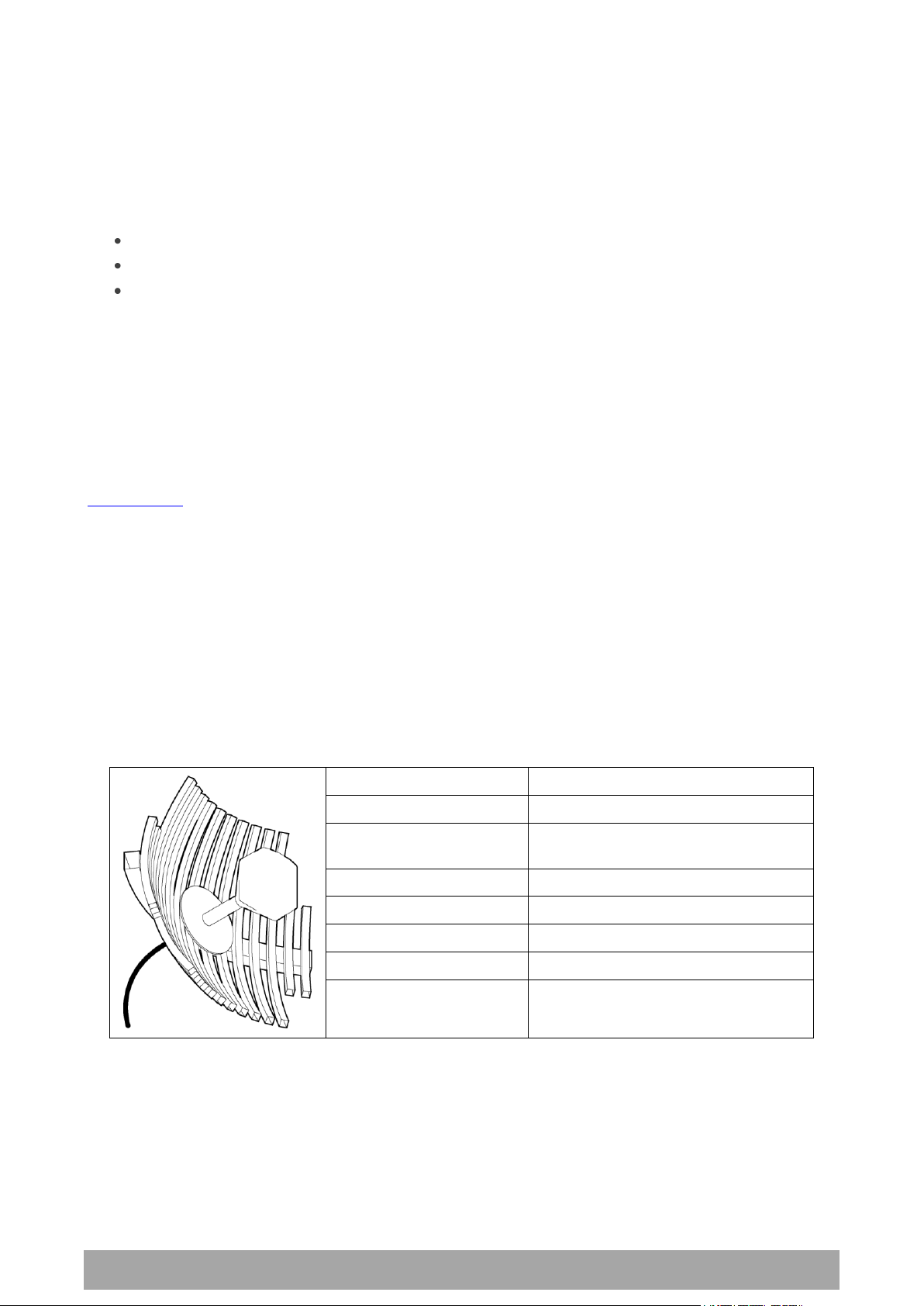
Factor
Explanation
Frequency
Often used in 1350-2700 MHz bands
Gain
Varies with size (17 dBi to 30 dBi
typical)
Wind loading
Can be significant
Tower aperture required
Can be significant
Size
Range from 0.6 m to 3 m diameter
Front to back ratio
Good
Cost
High
3. Preparation
Path Planning
Proper path planning is essential. When considering the components of your radio system, think about:
antenna selection and siting
coaxial cable selection
link budget
You can also use Surveyor to help you with path feasibility planning.
Surveyor is a path propagation calculator developed by 4RF to assist path planners quickly and efficiently
verify the viability of point-to-point transmission links deploying the Aprisa microwave radio systems.
The software program calculates the anticipated link performance for the transmission system elements
you have selected. However, it is not a substitute for in-depth path planning.
You will find Surveyor a valuable addition to your planning toolbox.
A copy of Surveyor is provided on the Aprisa CD supplied with this manual. You can download updates from
www.4rf.com.
Antenna Selection and Siting
Selecting and siting antennas are important considerations in your system design.
There are three main types of directional antenna that are commonly used with the radios parabolic grid,
Yagi and corner reflector antennas.
The antenna that should be used for a particular situation is determined primarily by the frequency of
operation and the gain required to establish a reliable link.
Parabolic Grid Antennas
24 | Preparation
Aprisa XE User Manual
Factor
Explanation
Frequency
Often used in 330-960 MHz bands
Gain
Varies with size (typically 11 dBi to 16
dBi)
Stackable gain increase
2 Yagi antennas (+ 2.8 dB)
4 Yagi antennas (+ 5.6 dB)
Wind loading
Less than a parabolic grid antenna
Tower aperture required
Unstacked: Less than a parabolic grid
antenna
Stacked: about the same as a
parabolic grid antenna
Size
Range from 0.6 m to 3 m in length
Front to back ratio
Low
Cost
Low
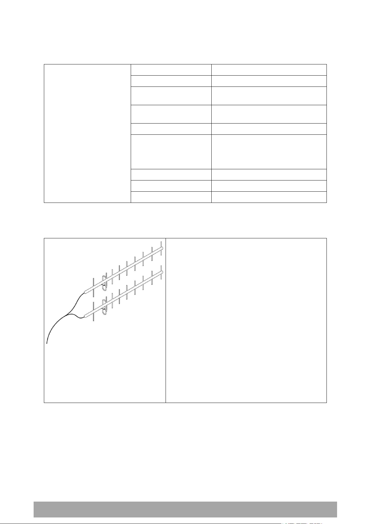
Yagi Antennas
It is possible to increase the gain of a Yagi antenna installation by placing two or more of them in a stack.
The relative position of the antennas is critical.
Example of stacked antennas
Preparation | 25
Aprisa XE User Manual
Factor
Explanation
Frequency
Often used in 330-960 MHz bands
Gain
Typically 10 dBd
Wind loading
Less than a parabolic grid antenna
Tower aperture required
About the same as a parabolic grid
antenna
Size
Range from 0.36 m to 0.75 m in length
Front to back ratio
High (typically 30 dB)
Beamwidth
Broad (up to 60°)
Cost
Medium
Corner Reflector Antennas
Antenna Siting
When siting antennas, consider the following points:
A site with a clear line of sight to the remote terminal is needed. Pay particular attention to trees,
buildings, and other obstructions close to the antenna site.
Example of a clear line-of-sight path
Any large flat areas that reflect RF energy along the link path, for instance, water, could cause
multipath fading. If the link path crosses a feature that is likely to cause RF reflections, shield the
antenna from the reflected signals by positioning it on the far side of the roof of the equipment
shelter or other structure.
Example of a mid-path reflection path
The antenna site should be as far as possible from other potential sources of RF interference such as
electrical equipment, power lines and roads.
The antenna site should be as close as possible to the equipment shelter.
Note: Wide angle and zoom photographs taken at the proposed antenna location (looking down the
proposed path), can be useful when considering the best mounting positions.

26 | Preparation
Aprisa XE User Manual
Factor
Effect
Attenuation
Short cables and larger diameter cables have less attenuation
Cost
Smaller diameter cables are cheaper
Ease of installation
Easier with smaller diameter cables or short cables
Coaxial Feeder Cables
To ensure maximum performance, it is recommended that you use good quality low-loss coaxial cable for
all feeder runs. For installations requiring long antenna cable runs, use Andrew Heliax™ or equivalent.
When using large diameter feeders, use a short flexible jumper cable between the feeder and the
terminal to reduce stress on the antenna port connector.
All coaxial cable has loss, that is, the RF energy traveling through it is attenuated. Generally speaking, the
larger the diameter of the cable, the less the loss. When selecting a coaxial cable consider the following:
When running cables:
Run coaxial cable from the installation to the antenna, ensuring you leave enough extra cable at each
end to allow drip loops to be formed.
For 19-inch rack mount installations, cables may be run from the front of the rack directly onto the
antenna port. They may also be run through the back of the rack to the front.
Terminate and earth or ground the cables in accordance with the manufacturers' instructions. Bond
the outer conductor of the coaxial feeder cables to the base of the tower mast.
Link Budget
All of the above factors (and many others not mentioned) combine in any proposed installation to create a
link budget. The link budget predicts how well the radio link will perform after it is installed.
Use the outputs of the link budget during commissioning testing to confirm the link has been installed
correctly, and that it will provide reliable service.

Preparation | 27
Aprisa XE User Manual
WARNING:
Before connecting power, ground the chassis using the safety earth terminal on the
front panel.
Operating temperature
-10°C to +50°C
Storage temperature
-20°C to +70°C
Humidity
Maximum 95% non-condensing
Site Requirements
Power Supply
Ensure that the correct power supply is available for powering the terminal.
The nominal input voltage for a terminal is 12, 24 or 48 volts DC or 115 / 230 volts AC rms.
The DC supply voltage is factory preset at time of order and cannot be adjusted in the field.
The terminal voltage is indicated on the chassis label by the DC input connector and on the specification
label fitted to the terminal.
Equipment Cooling
Mount the terminal so that air can flow through it. Do not obstruct the free flow of air around the
terminal. The two internal, speed-controlled fans fitted into the chassis provide sufficient cooling.
The operation of the fans is monitored and an alarm is raised under failure conditions.
The environmental operating conditions are as follows:

28 | Preparation
Aprisa XE User Manual
WARNING:
Lightning can easily damage electronic equipment.
To avoid this risk, install primary lightning protection devices on any interfaces that
are reticulated in the local cable network.
You should also install a coaxial surge suppressor on the antenna port of the duplexer.
Earthing and Lightning Protection
Earth the antenna tower, feeders and lightning protection devices in accordance with the appropriate
local and national standards. The diagram below shows the minimum requirements.
Use grounding kits as specified or supplied by the coaxial cable manufacturer to properly ground or bond
the cable outer.

About the Terminal | 29
Aprisa XE User Manual
4. About the Terminal
Introduction
The terminals operate in a number of frequency bands from 300 MHz up to 2.7 GHz carrying ethernet,
voice and data traffic over distances up to 100 kilometres.
They are designed to meet the demands of a wide range of low to medium capacity access and backhaul
applications.
The digital access terminal is a compact, powerful point-to-point linking solution with up to 64 Mbit/s of
radio link capacity, and customer-configurable interface options integrated within the radio platform.

30 | About the Terminal
Aprisa XE User Manual
Modules
The terminal is modular in design, which helps reduce mean time to repair (MTTR). It is designed for 19inch rack mounting and is only 2U high for standard configurations.
The five main modules housed inside the chassis are the transceiver, modem, motherboard, power supply,
and duplexer. Interface cards are fitted into the eight interface slots on the motherboard. Modules are
interconnected via several buses on the motherboard. A duplexer can be mounted inside or outside the
chassis.
The interrelationships between the components are shown below:

About the Terminal | 31
Aprisa XE User Manual
No.
Label
Description
1
AC or DC power input
DC and AC power supplies are available (AC is shown)
2
Safety earth stud
An M5 stud for connection to an external protection ground for
protection against electric shock in case of a fault.
3
Antenna connector
N-type 50Ω female connector for connection of antenna feeder
cable.
4
Interface slots A to H
Eight interface slots on the motherboard to fit interface cards.
5
ETHERNET
Integrated four-port layer 2 switch.
6
SETUP
RJ-45 serial connection to PC for initial configuration.
7
ALARM
RJ-45 connector for two external alarm input and four external
alarm output connections.
8
LED indicators
OK
Indicates normal operation and minor and major alarm
conditions.
RX
Indicates status of receive path including normal operation and
alarms such as BER, RSSI and loss of synchronization.
TX
Indicates status of transmit path including normal operation
and alarms such as forward / reverse power and temperature.
ON
Blue LED indicates that there is power to the terminal.
9
RSSI
RSSI test point suitable for 2 mm diameter multimeter test
lead pin.
Front Panel Connections and Indicators
All connections to the terminal are made on the front panel of the terminal.

32 | About the Terminal
Aprisa XE User Manual
Name
Interface card type
Function
QJET
Quad E1/T1 interface card
Four E1 / T1 interfaces (Framed or Unframed).
Q4EM
Quad 4 wire E&M interface card
Four 4 wire E&M voice channels
DFXS
Dual 2 wire FXS interface card
Two 2 wire loop signalling foreign exchange
subscriber (POTS) channels
DFXO
Dual 2 wire FXO interface card
Two 2 wire loop signalling foreign exchange office
channels
HSS
High-Speed Synchronous
interface card
A single high speed serial data channel configured
as synchronous V.24, V.35, X.21, V.36 / RS-449,
or RS-530.
QV24
Quad V.24 serial interface card
Four V.24 / RS-232 serial data channels
Synchronous and asynchronous
Interface Card Types
Each terminal has eight interface slots labeled A to H. Each slot can be fitted with any interface card
type. Typically, the terminal is delivered pre-configured with the requested interface cards.
The following interface card types are currently available:

Mounting and Installing the Terminal | 33
Aprisa XE User Manual
CAUTION:
You must comply with the safety precautions in this manual or on the product itself.
4RF Limited does not assume any liability for failure to comply with these
precautions.
5. Mounting and Installing the Terminal
This section covers installing the hardware associated with the terminal. Before you begin a terminal
installation, read this section thoroughly.
Required Tools
No special tools are needed to install the terminal other than those required to physically mount the
terminal into the rack.
Installing the Terminal
The terminal is designed for 19-inch rack mounting and is supplied with rack mounting brackets. The rack
brackets can be front, mid, or rear mounted (as shown below) to suit individual installation requirements.
Once the rack brackets are attached, carefully lift the terminal into position in the rack, and fasten with
screws and washers.

34 | Mounting and Installing the Terminal
Aprisa XE User Manual
WARNING:
When the link is operating, there is RF energy radiated from the antenna.
Do not stand in front of or touch the antenna while the terminal is operating.
Installing the Antenna and Feeder Cable
Carefully mount the antenna following the antenna manufacturers' instructions. Run feeder cable from the
antenna to the terminal mounting location.
Lightning protection must be incorporated into the antenna system. For more information, please contact
Customer Support.
1. Fit the appropriate male or female N-type connector to the antenna feeder at the antenna end.
Carefully follow the connector manufacturers' instructions.
2. Securely attach the feeder cable to the mast and cable trays using cable ties or cable hangers. Follow
the cable manufacturer's recommendations about the use of feeder clips, and their recommended
spacing.
3. Connect the antenna and feeder cable. Ensure the N-type connector is tight. Weatherproof the
connection with a boot, tape, or other approved method.
4. Fit the appropriate N-type male connector to the antenna feeder at the terminal end (the terminal is
N-type female). Carefully follow the connector manufacturer's instructions.
5. Connect the feeder cable to the antenna port on the terminal. Use a jumper cable, if needed. Ensure
the N-type connector is tight.
6. Connect a coaxial surge suppressor or similar lightning protector between the feeder and jumper
cables (or at the point where the cable enters the equipment shelter).
Earth the case of the lightning protector to the site Lightning Protection Earth. Also earth the terminal
M5 earth stud to a protection earth.

Mounting and Installing the Terminal | 35
Aprisa XE User Manual
RJ-45 pin
Connection description
TIA-568A wire colour
1
External alarm input 1
green / white
2
External alarm input 2
green
3
Common reference for alarm inputs 1 to 2
orange / white
4
Common reference for alarm outputs 1 to 4
blue
5
External alarm output 1
blue / white
6
External alarm output 2
orange
7
External alarm output 3
brown / white
8
External alarm output 4
brown
External Alarms
Two external alarm inputs and four external alarm outputs are provided on the RJ-45 ALARM connector on
the front panel. These enable an internal alarm to provide an external alarm to the network operator's
existing network management system via contact closure or opening, or for an external alarm to be
transported via the radio link.
The latency for an alarm presented on an external alarm input to the alarm being output on an external
alarm output is < 2 seconds.
Alarm outputs are isolated semiconductor relay type contacts rated 0 to 60 VDC or AC rms with a
maximum current of 100 mA.
Alarm inputs are isolated current detectors with an operating voltage range of 9 to 60 VDC or AC rms
(effective current threshold of 5.0 to 6.5 mA constant current).
The common reference potential for the two external alarm inputs must be applied to pin 3 and the
common reference potential for the four external alarm outputs must be applied to pin 4.
Alarm Circuit Setup
A typical alarm circuit setup is:
An external battery applied to the ‘common alarm inputs reference’ and a normally open relay
contact connected to the alarm input. Closing the contact applies the source to the alarm input
detector which turns the alarm on (setup for ‘alarm on when source on’). See ‘Configuring the
External Alarm Inputs’ on page 81 for the setup options.
An external earth applied to the ‘common alarm outputs reference’ and a ground contact detector
connected to the alarm output. When the alarm is on (active), the external alarm output relay contact
closes (setup for ‘relay closed when alarm on’). See ‘Configuring the External Alarm Outputs’ on page
83 for the setup options.
The terminal front panel RJ-45 ALARM connections are:

36 | Mounting and Installing the Terminal
Aprisa XE User Manual
Interface Cabling
All interface cabling connections are made with RJ-45 male connectors which plug into the front of the
interface cards (see ‘Interface Connections’ on page 257).
QJET Q4EM DFXO and DFXS
The cabling to the QJET, Q4EM, DFXO and DFXS interface cards must have a minimum conductor size of
0.4 mm2 (26 AWG).
Ethernet
Standard Ethernet network cables are used for all Ethernet port cabling.

Mounting and Installing the Terminal | 37
Aprisa XE User Manual
WARNING:
Do not apply power to the terminal until you have completed installing the interface
cards and connecting the antenna.
Before disconnecting the safety earth during maintenance, remove AC or DC power
supply connections, antenna cable and all interface cables from the terminal.
Nominal voltage
Input voltage
range
Maximum Power
input
Maximum input
current
Recommended
DC breaker
rating
+12 VDC LP
10.5 to 18 VDC
53 W
5 A
8 A
±12 VDC
10.5 to 18 VDC
180 W
18 A
25 A
±24 VDC
20.5 to 30 VDC
180 W
8 A
10 A
±48 VDC
40 to 60 VDC
180 W
4 A
5 A
Power Supplies
US and Canada: Installations should be in accordance with US National Electrical Code ANSI / NFPA 70,
and Canadian Electrical Code, Part 1 C22.1.
DC Power Supply
There are four DC power supply options for the terminal; 12 VDC, 12 VDC Low Power, 24 VDC and 48 VDC.
The DC inputs are polarity critical so the DC voltage must be applied with the correct polarity.
CAUTION: An all-pole switch or DC circuit breaker of the rating shown in the table above must be fitted
between the terminal DC input and the DC power source.
Each terminal or MHSB terminal should have its own separate fuse or DC circuit breaker.
12 VDC / 24 VDC / 48 VDC Power Supply
The power supply DC input is isolated from ground, so the DC power input can be either positive grounded
or negative grounded. The positive or negative terminal should be connected to ground.
12 VDC LP Power Supply
The 12 VDC Low Power is a high efficiency power supply for low power consumption applications up to a
maximum of 53 watts input power (see ‘Power Consumption’ on page 312).
The DC input on this power supply is not isolated from ground as the negative input is internally connected
to ground via the Aprisa XE chassis. The DC power input for this power supply must be a positive 12 V
supply with the negative grounded.

38 | Mounting and Installing the Terminal
Aprisa XE User Manual
Terminal
Power input
Cable colour
+V
Positive DC input
Red
-V
Negative DC input
Black
DC Power Input Cabling
The DC power input is terminated on the front panel of the terminal with two high-current M3 screw
clamps for the positive and negative DC input and a M5 stud for the earth connection.
The DC power cables have pre-terminated lugs to fit into the power input M3 screw clamps on one end and
bare wire at the other end.
The appropriate power cable for the power supply ordered is included in the accessory kit.
12 VDC LP / 24 VDC / 48 VDC Cable
The 12 VDC LP, 24 VDC and 48 VDC power supplies are supplied with a 3 metre red / black cable of
2.0 mm2 (23 strands of 0.32 mm2).

Mounting and Installing the Terminal | 39
Aprisa XE User Manual
Terminal
Power input
Cable colour
+V
Positive DC input
Red
-V
Negative DC input
Black
1. Fit both pairs of lugs into the terminal screw
clamps.
2. Twist the other ends together when fitting
to the source.
12 VDC Cable
The 12 VDC power supply is supplied with a 3 metre red/black cable of two pairs of 2.3 mm2 (72 strands of
0.2 mm2) making a total of 4.6 mm2 per connection. This increase in wire size is to carry the increased
current consumption of the 12 VDC supply (max 18 Amps per terminal).
This 3 metre cable is engineered to power a fully loaded terminal from a 12 VDC supply. A longer cable
should not be used as the additional voltage drop could cause the power supply to fail.
If longer cable runs are required between the 12 VDC power supply and the terminal, it is suggested that
high current distribution bus bars are used to feed the rack and the supplied power cable used between
the bus bars and the terminals.

40 | Mounting and Installing the Terminal
Aprisa XE User Manual
Nominal
voltage
Input voltage
range
Maximum Power
input
Max VA
Frequency
115 VAC
103 - 127 Vrms
180 W
400 VA
47 - 63 Hz
230 VAC
207 - 254 Vrms
180 W
400 VA
47 - 63 Hz
Terminal
Power input
Cable colour
E
Earth
Green/yellow
N
Neutral
Blue
L
Line / Phase
Brown
AC Power Supply
There is one AC power supply for the terminal. This AC power supply is auto-sensing to operate with a
nominal input voltage of 115 Vrms or 230 Vrms.
The power input is terminated on the front panel of the terminal using a standard IEC plug. This power
supply has a power on/off switch.
A power cable is included in the accessory kit and is pre-fitted with an IEC socket connector and the
country-specific plug that was specified when the order was placed.
Important: Please check with your local power authority about correct colour usage and pinouts.
AC power cords used must be in accordance with national requirements.
Norway and Sweden: PLUGGABLE CLASS I EQUIPMENT intended for connection to a telephone network or
similar communications system requires a label stating that the equipment must be connected to an
earthed mains socket outlet.

Mounting and Installing the Terminal | 41
Aprisa XE User Manual
Brownout Recovery Module
A Brownout Recovery Module (BRM) is factory fitted to the Aprisa XE motherboard power connector when
the radio is fitted with an AC power supply.
The AC power supply has a safety mechanism that trips the power if it detects a power input brownout.
The BRM restarts the power supply after 3 seconds.

42 | Mounting and Installing the Terminal
Aprisa XE User Manual
Safety Earth
The terminal chassis must have a protection / safety earth connected between the terminal earth stud
and a common protection earth in the rack. The DC power input can be either positive grounded or
negative grounded depending on the power supply system available.
Ground the terminal chassis using the terminal earth stud on the front panel as shown:

Mounting and Installing the Terminal | 43
Aprisa XE User Manual
Bench Setup
Before installing the link in the field, it is recommended that you bench-test the link. A suggested setup
for basic bench testing is shown below:
When setting up the equipment for bench testing, note the following:
Earthing—the terminal should be earthed at all times. The terminal earth stud must be connected to a
protection earth.
Attenuators— In a bench setup, there must be 60 - 80 dB at up to 3 GHz of 50 ohm coaxial attenuation
(capable of handling the transmit power of +35dBm) between the terminals’ N type antenna
connectors.
This can be achieved with two fixed attenuators fitted to the antennas 'N' connectors and a variable
attenuator with a ≥ 60 dB range. You can use other attenuator values as long as you consider the
transmit power output level (max +33 dBm) and the receiver signal input (max -20 dBm).
Cables—use double-screened coaxial cable that is suitable for use up to 3 GHz at ≈ 1 metre.
CAUTION: Do not apply signals greater than -20 dBm to the antenna connection as they can damage the
receiver.


Connecting to the Terminal | 45
Aprisa XE User Manual
Console port
(DCE, RJ-45)
RJ-45 to RJ-45 cable
RJ-45 to DB-9 adaptor
PC port
(DTE, DB-9)
Signal
RJ-45 pin
RJ-45 pin
RJ-45 pin
DB-9 pin
Signal
RTS 1 1 1 7
RTS
DTR 2 2 2 4
DTR
TXD 3 3 3 3
TXD
GND 4 4 4 5
GND
GND 5 5 5 NC
NC
RXD 6 6 6 2
RXD
DSR 7 7 7 6
DSR
CTS 8 8 8 8
CTS
6. Connecting to the Terminal
Connecting to the Terminal's Setup Port
You can configure basic terminal settings by connecting to the terminal using the Setup cable. This can be
useful if you need to confirm the terminal's IP address, for example.
You can password-protect the setup menu to prevent unauthorized users from modifying terminal settings.
A straight RJ-45 connection cable and a RJ-45 to DB-9 adapter is provided with each terminal.
1. Plug the DB-9 into serial port of the PC.
2. Plug the RJ-45 connection cable into the adaptor as shown below:
3. Plug the other end of the RJ-45 connection cable into the SETUP port of the terminal.
Note: Connecting the PC serial port to the Interface Cards or ALARM connectors may result in damage
to the PC or terminal.
Ensure that the RJ-45 connection cable is connected to the RJ-45 connector marked 'SETUP'.
Cable pinouts (RJ-45 to DB-9)
If you need a conversion connector or cable, refer to the following table:

46 | Connecting to the Terminal
Aprisa XE User Manual
Bits per second
115200
Data bits
8
Parity
None
Stop bits
1
Flow Control
None
Configure the PC COM Port Settings
Terminal emulation software e.g. HyperTerminal is used to setup the basic configuration of a terminal.
The PC's COM port settings must be setup as follows:
Start a HyperTerminal Session
1. On the PC, select Start > Programs > Accessories > Communications > HyperTerminal.
2. Enter a name for the connection and click OK.
3. Select the designated COM Port from the Connect Using drop-down box. Ensure it is the same COM
port that you configured earlier on your PC. Click OK.
Note: The Country/region, Area code, and Phone number information will appear automatically.

Connecting to the Terminal | 47
Aprisa XE User Manual
4. Set the COM Port settings as follows:
5. When you have completed the settings, click OK, which will open the HyperTerminal window.
6. Apply power to the terminal.
Note: If power was applied to the terminal before launching HyperTerminal, hit the Enter key to
initiate the link.
When the terminal has completed startup, you will be presented with the Setup menu:

48 | Connecting to the Terminal
Aprisa XE User Manual
Connecting to the Terminal's Ethernet Interface
The main access to a terminal for management is with the ethernet interface using standard IP
networking. There should be only one ethernet connection from the terminal to the management network.
The terminals are pre-configured to use IP addressing in one of the common 'non-routable' IP address
ranges. This means the terminals are usually recognized by your operating system without any
reconfiguration.
However, you should change these default addresses (see ‘Changing the Terminal’s IP Address’ on page
64) to comply with your IP addressing scheme.
In the example below, the active management PC must only have one connection to the link as shown by
path . There should not be any alternate path that the active management PC can use via an alternate
router or alternate LAN that would allow the management traffic to be looped as shown by path .

Connecting to the Terminal | 49
Aprisa XE User Manual
PC Requirements for SuperVisor
SuperVisor requires the following minimum PC requirements:
Microsoft Windows 2000, NT, XP, Vista or Windows 7
Personal computer with 1.6 GHz Pentium IV
512 MB of RAM
200 MB of free hard disk space
Ethernet interface (Local Area Network)
COM port
Web browser with a Java plug-in such as Mozilla FireFox (recommended), Microsoft Internet
Explorer 5.0, or Netscape Navigator 6.0, but SuperVisor also supports other major web browsers.
Java JRE 1.6.
Note: Mozilla Firefox, Internet Explorer and the Java JRE are provided on the Aprisa CD (see ‘Aprisa XE CD
Contents’ on page 20).

50 | Connecting to the Terminal
Aprisa XE User Manual
PC Settings for SuperVisor
To change the PC IP address:
If your PC has previously been used for other applications, you may need to change the IP address and the
subnet mask settings. You will require Administrator rights on your PC to change these.
Windows XP example: Configure IP settings
1. Open the 'Control Panel'.
2. Open 'Network Connections' and right click on the 'Local Area Connection' and select 'Properties'.
3. Click on the 'General' tab.
4. Click on 'Internet Protocol (TCP/IP)' and click on properties.
5. Enter the IP address and the subnet mask (example as shown).
6. Click 'OK' then close the Control Panel.
If the terminal is on a different subnet from the network the PC is on, set the PC default gateway address
to the network gateway address which is the address of the router used to connect the subnets (for
details, consult your network administrator).

Connecting to the Terminal | 51
Aprisa XE User Manual
To change the PC connection type:
If your PC has previously been used with Dial-up connections, you may need to change your PC Internet
Connection setting to 'Never dial a connection'.
Windows XP example: Configure Windows to Never Dial a Connection
1. Open the 'Control Panel'.
2. Open 'Internet Options' and click on the 'Connections' tab.
3. Click the 'Never dial a connection' option.
4. Click 'OK' then close the Control Panel.

52 | Connecting to the Terminal
Aprisa XE User Manual
To change the PC pop-up status:
Some functions within SuperVisor require Pop-ups enabled e.g. saving a MIB
Windows XP example: Configure explorer to enable Pop-ups
1. Open the 'Control Panel'.
2. Open 'Internet Options' and click on the 'Privacy' tab.
3. Click on 'Settings'.
4. Set the 'Address of Web site to allow' to the terminal address or set the 'Filter Level' to 'Low: Allow
Pop-ups from secure sites' and close the window.
5. Click 'OK' then close the Control Panel.

Connecting to the Terminal | 53
Aprisa XE User Manual
IP Addressing of Terminals
When logging into a link, it is important to understand the relationship between the Local / Remote and
the Near end / Far end terminals.
The Near end terminal is the terminal that has its ethernet port physically connected to your IP network.
The Far end terminal is the terminal that is at the other end of the link from the Near end terminal and
communicates through the management connection over the radio link to the Near end terminal.
The Local terminal is the terminal that SuperVisor is logged into and is displayed on the left hand side of
the SuperVisor screen. The Local terminal can be the Near end or Far end terminal.
The Remote terminal is the terminal that is at the other end of the link from the Local terminal and is
displayed on the right hand side of the SuperVisor screen.
To prevent confusion when operating SuperVisor, determine the IP address of the Near end terminal and
log into that terminal. This is now the Local terminal.
The distinction is important as:
Some functions can only be carried out on the Local terminal.
Having different configurations at each end of the link will disrupt communications between the
terminals. In these circumstances it is important to make changes to the Far end terminal of the link
first. The link is then lost only until the near end configuration is completed and communication
restored.
If the Near end terminal is modified first, the link is lost for much longer as staff will have to either
physically visit the Far end terminal to restore the link, or restore the near end to match the far end,
re-establish the link, then start the process again, this time with the Far end terminal first.

54 | Connecting to the Terminal
Aprisa XE User Manual
Network IP Addressing
Same Subnet as the Local PC
The following diagram shows a link interconnected on the same subnet as the local PC terminal used for
configuration.
In this example, the local PC, as well as the local and remote terminals, are on the same subnet and
therefore have the same subnet mask 255.255.255.0.
This will allow the PC and the terminals to communicate with each other.

Connecting to the Terminal | 55
Aprisa XE User Manual
Different Subnet as the Local PC
The following diagram shows a link interconnected on a different subnet as the local PC used for
configuration, and communicating through a network. This can be achieved on the condition that network
router(s) 1 and 2 are programmed to recognize each other and the various subnets on the overall network.


Managing the Terminal | 57
Aprisa XE User Manual
Selection
Explanation
1)
Dump terminal
configuration
This shows basic terminal data such as Terminal ID, IP data
and radio parameters of TX and RX frequency, TX power,
modulation type and channel size.
2)
Not used
3)
Configure IP addresses
Use this if you want to set the IP address, subnet mask or
gateway address of the local terminal.
4)
Configure SNMP
Use to display SNMP settings, setup the SNMP Access Controls
and Trap Destinations and reset SNMP settings to defaults.
5)
Set hostname
Use this to set a name that can be used in conjunction with
DNS.
6)
Configure remote
terminal address
Use this to set the IP address of the remote terminal.
7)
Reset web server users
Deletes all existing usernames and passwords in the ‘User
Table’ and restores default usernames and passwords.
8)
Not used
9)
Reboot
Reboots the terminal.
10)
Configure Ethernet
Use this to display the Ethernet configuration and reset the
Ethernet settings to the defaults.
11)
Password Protect Menu
Use this to password-protect the menu to prevent
unauthorized users from modifying terminal settings.
The password is setupxe.
7. Managing the Terminal
The command line setup menu can be used to:
Provide basic access to the terminal to set IP addresses
Check or set basic settings of the terminal
4RF SuperVisor is an embedded element manager for the Aprisa XE terminal which is used to:
Configure radio and interface parameters
Setup cross connections between traffic interfaces
Monitor performance, terminal status and alarm details
The Setup Menu
1. Initiate the link by either applying power to the terminals or, if the terminals are already powered up,
pressing the Enter key.
2. At the prompt, enter your selection:

58 | Managing the Terminal
Aprisa XE User Manual
To Get or Set the IP Address of a Terminal Using Setup
To get the IP address of a terminal using setup:
1. At the prompt, type 1 and enter.
The following information appears:
the IP addresses of the local and remote terminals
the subnet mask and gateway of the local terminal
the TFTP of the remote terminal
To set the IP address of a terminal using setup:
1. At the prompt, enter 1.
2. Enter 3 to configure the local terminal IP address.
Set the following for the terminal using the standard format xxx.xxx.xxx.xxx:
1) IP address
2) Subnet mask
3) Gateway address
3. Enter 4 (Quit) to return to the main menu.
4. Enter 6 to configure the remote terminal IP address.
Important: You must ensure that the IP addresses of the local and remote terminals are on the same
subnet as the PC being used to configure the terminals.
5. Enter 4 (Quit) to return to the main menu.
6. Enter 9 (Are you sure y/n) to reboot the terminal.

Managing the Terminal | 59
Aprisa XE User Manual
SuperVisor
The SuperVisor management software is pre-loaded into an integrated web-server within the terminal.
SuperVisor runs on any Java-enabled web browser.
You can use SuperVisor to:
display and configure terminal parameters
view the terminal alarms
monitor the performance and status of the link
upgrade the terminal software
save and load configuration files
save performance and error information to a log file

60 | Managing the Terminal
Aprisa XE User Manual
SuperVisor Logging In
The maximum number of concurrent users that can be logged into a terminal is 5.
If SuperVisor is inactive for a period of 30 minutes, the terminal will automatically log out the user.
To log in to SuperVisor:
1. Open your web browser and enter the IP address of the terminal.
Note: If you haven't yet assigned IP addresses to the terminals, use the factory-configured IP addresses
(see ‘Changing the Terminal’s IP Address’ on page 64).
If you don't know the IP address of the terminal, you can determine it using terminal emulation
software (see ‘To Get or Set the IP Address of a Terminal Using Setup’ on page 58).
2. Login with the user name and password assigned to you.
Note: If unique user names and passwords have not yet been configured, use the default user names
and passwords (see ‘Setting up users’ on page 65).
Important: After you login for the very first time, it is recommended that you change the default
admin password for security reasons (see ‘Changing passwords’ on page 67).
3. Tick the ‘Use Popup Window’ tick box if you want a separate browser window to launch after you have
logged in. The login page remains open in one window allowing you to view or configure settings in
another page. This is useful if you have more than one link to configure, for example, protected
terminals.
4. When you have logged in, the Summary page shows a summary of both the Local and Remote
terminals’ parameters.

Managing the Terminal | 61
Aprisa XE User Manual
SuperVisor Logging Out
As the maximum number of concurrent users that can be logged into a terminal is 5, not logging out
correctly can restrict access to the terminal until the after the timeout period (30 minutes).
Logging out from a terminal will logout all users logged in with the same user name.
If the SuperVisor window is closed without logging out, the terminal will automatically log the user out
after a timeout period of 30 minutes.
To log out of SuperVisor:
1. Click on the ‘Logout’ button on the Summary Bar.

62 | Managing the Terminal
Aprisa XE User Manual
SuperVisor Main Screen
The SuperVisor Main Screen presents a summary of both the local and remote terminals and the status of
the terminal front panel LED indicators:
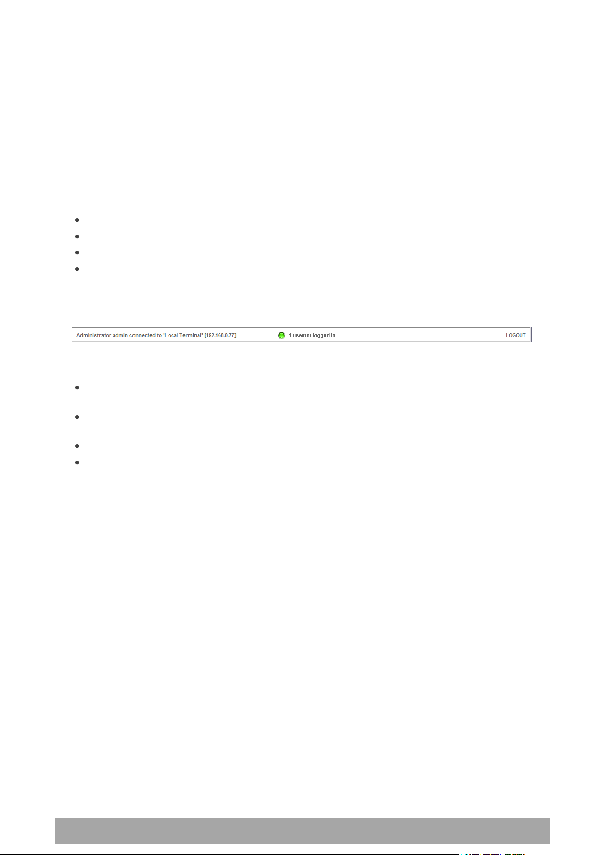
Managing the Terminal | 63
Aprisa XE User Manual
SuperVisor Menu Bar
The SuperVisor Menu Bar at the top of the screen shows the names of the terminals, the top level menus
and three status indicators for both the local and remote terminals. These indicators reflect the status
LED indicators on the front panel of terminal.
There are four menus available:
Link - menu options for both terminals in a link
Local - menu options for the local terminal in a link
Remote - menu options for the remote terminal in a link
Help - provides details about the terminal
SuperVisor Summary Bar
The SuperVisor Summary Bar at the bottom of the screen shows:
The login name of the person currently logged in together with the name of the local terminal and
its IP address.
A login alarm that indicating that someone else has logged into and could be working on the same
link. The LED is green for 1 user and yellow for more than 1 user.
The number of users logged in to the link
A SuperVisor logout button

64 | Managing the Terminal
Aprisa XE User Manual
Terminal
IP address
Unprotected terminals
Terminal 1 (local)
169.254.50.10
Terminal 2 (remote)
169.254.50.20
Protected terminals
Terminal 1, terminal A (local)
169.254.50.10
Terminal 1, terminal B (local)
169.254.50.11
Terminal 2, terminal A (remote)
169.254.50.20
Terminal 2, terminal B (remote)
169.254.50.21
Changing the Terminal’s IP Address
You can use SuperVisor to change the IP address of the terminal from the default. Alternatively, you can
assign the IP address using the SETUP port (see ‘To Get or Set the IP Address of a Terminal Using Setup’ on
page 58).
To change the IP address of the terminals using SuperVisor:
1. Launch your web browser and connect to the terminal using the one of the factory-configured default
IP addresses shown below:
Note: The factory default settings for the subnets is 255.255.0.0; the gateway is 0.0.0.0.
2. Log into the terminal as the administrator with the user name 'admin' and the password 'admin'.
Note: For security reasons, change the admin password (see ‘Changing passwords’ on page 67) as soon
as possible.
3. Select Link or Local or Remote > Terminal > Advanced and make the necessary changes.
Note: If this IP address change is being made over the RF link, it is important to change the far end of
the link first.
4. Once you have changed the IP address of a terminal, you must perform a hard reboot of the terminal
and then reconnect to it using the new IP address.

Managing the Terminal | 65
Aprisa XE User Manual
User
Group
Default
User Name
Default
Password
Access Rights
View
view
view
Users in this group can only view terminal parameters.
Modify
modify
modify
Users in this group can view and edit terminal parameters.
Admin
admin
admin
Users in this group have full access to all terminal
parameters including the ability to add and change users.
Setting Up Users
Note: You must login with 'admin' privileges to add, disable, delete a user or change a password.
User groups
There are three pre-defined user groups to allocate access rights to users. These user groups have
associated default user names and passwords of the same name.
Adding a User
1. Select Local or Remote > Maintenance > User Admin > User Table.
2. Select an empty line (that isn't allocated to an existing user) and then click Edit.
3. Enter the user name.
A user name can be up to 32 characters but cannot contain back slashes, forward slashes, spaces,
tabs, single or double quotes.
4. Enter the Password and the Confirm Password.
A password can be up to 32 characters but cannot contain back slashes, forward slashes, spaces, tabs,
single or double quotes.
5. Select the group that they will belong to (View, Modify, or Admin).
6. If the user requires immediate access, enable the user by clicking on Yes.
7. Click Apply.
Note 1: The new user must be setup on both the Local and Remote terminals.
Note 2: For the changes to take effect, you must reboot the terminal (Local > Maintenance > Reboot).

66 | Managing the Terminal
Aprisa XE User Manual
Disabling a User
1. Select Local or Remote > Maintenance > User Admin > User Table.
2. Select the user who you want to disable.
3. Click Edit to display the User details and set Enabled to 'No'.
4. When you have made your changes, click Apply to apply changes or Reset to restore the previous
configuration.
Note: For the changes to take effect, you must reboot the terminal (Local > Maintenance > Reboot).
Deleting a User
1. Select Local or Remote > Maintenance > User Admin > User Table.
2. Select the user you want to delete.
3. Click Edit to display the user details and delete the User Name and Password.
4. Reset the Group to 'View' and set Enabled to 'no'.
5. When you have made your changes, click Apply to apply changes or Reset to restore the previous
configuration.
Note: For the changes to take effect, you must reboot the terminal (Local > Maintenance > Reboot).
Saving User Information
You can save the list of users to your PC and then load this file to another terminal. This is useful if you
have multiple terminals to configure.
To save the user table to file:
1. Select Local > Maintenance > User Admin > Save User List.
2. Select the 'Save to disk' option in the dialog box that appears.
3. In the next dialog box that appears, navigate to the directory where you want to save the file, enter a
suitable filename, and then click Save (The default name for this file is 'downloadUsers').
Note: If this dialog box does not appear, change your Internet security settings to allow downloads.
You may also need to check your file download location setting.
To save the file to another terminal:
1. Select Local > Maintenance > User Admin > Load User List.
2. On the Upload Users page, select Browse and navigate to the file on your PC.
3. Click Apply.
The User Table appears and you can edit users, as required.

Managing the Terminal | 67
Aprisa XE User Manual
Changing Passwords
1. Select Local or Remote > Maintenance > User Admin > User Table.
2. Select the user whose password you want to change and click Edit.
3. Enter the new Password and the new Confirm Password.
A password can be up to 32 characters but cannot contain back slashes, forward slashes, spaces, tabs,
single or double quotes.
4. When you have made your changes, click Apply.
Viewing User Session Details
Administrators can check who is currently logged in, the computer they are logging in from, and how long
they have been logged in for.
Note: A 'session' is the period of time that begins when someone logs into the terminal and ends when
they logout.
To view user session details:
1. Select Local > Maintenance > User Admin > Session Details.
The 'Session Details' shows a list of the current users:
User Name: the User Name logged into the terminal.
Time: the number of minutes the user has been logged in.
Last Access: the number of minutes the user last accessed the terminal in this session.
Address: the address of the computer or proxy server address logged into the terminal.


Configuring the Terminal | 69
Aprisa XE User Manual
8. Configuring the Terminal
Configuring the RF Settings
The RF settings are factory-configured before dispatch to the customer requirements. However, you can
change the RF settings, if required.
If two fundamental radio parameters (RX and TX frequency or modulation) are changed on the remote
terminal in the same apply action (simultaneously), the first parameter change could break the
communications link to the remote terminal and prevent the other commands from being actioned. There
is a two second delay between receiving the command and actioning it to allow for subsequent commands
to be received before the communications link is lost.
To configure RF settings:
Select Link or Local or Remote > Terminal > Basic:
Note: Transmit frequency, transmit power, channel size, modulation and antenna polarization would
normally be defined by a local regulatory body and licensed to a particular user.
Refer to your site license details when setting these fields.

70 | Configuring the Terminal
Aprisa XE User Manual
RX and TX Frequency
The local terminal transmit frequency must match the receive frequency of the remote terminal and the
remote terminal transmit frequency must match the receive frequency of the local terminal.
When setting the RX and TX frequency with SuperVisor, the frequency entered is automatically resolved to
the synthesizer step size for the terminal frequency band e.g. an ETSI 1400 MHz band frequency entry of
1474,010,000 Hz will be changed to 1474,012,500 Hz (see synthesizer step size in the table ‘Frequency
Bands’ on page 287).
The RX and TX frequency entered must be:
Within the frequency band limits of the chosen RF frequency band of the terminal as specified in
‘Frequency Bands’ on page 287. e.g. for an ETSI frequency band of 1400 MHz, the frequency band
limits are 1350 to 1550 MHz.
Within the TX / RX passband of the duplexer fitted in the terminal e.g. for a frequency band of
1400 MHz, the standard duplexer passband is 7 MHz and the TX / RX split is 48 MHz (see Duplexer
(bandpass) ‘Duplexers’ on page 301).
The duplexer passband and center frequencies are written on the duplexer label.
The TX and RX frequencies are validated against the duplexer parameters entered on SuperVisor Link or
Local or Remote > Terminal > Duplexer (see ‘Setting the Duplexer Parameters’ on page 79).
If the TX or RX frequency entered is not valid i.e. outside the operating range of the duplexer, a warning
message will popup. OK accepts the frequency entered and cancel rejects the frequency entered.
Important: Changing the remote terminal RX or TX frequency will disable all management communication
to the remote terminal but by changing the local terminal to match the remote terminal, the radio link
will be restored as will the management communication
BUT if the remote terminal RX or TX frequency is changed to be outside the operating range of the
terminal, changing the local terminal to match the remote terminal will not restore the radio link and all
management communication will be lost.
The remote terminal TX and RX frequencies cannot be changed simultaneously i.e. change one direction
and ‘Apply’ the change and then change the other direction and ‘Apply’ the change.
To change both TX and RX frequencies:
1. Change the remote terminal RX frequency and ‘Apply’ the change. The radio link will fail.
2. Change the local terminal TX frequency to that of the remote RX frequency and ‘Apply’ the change.
The radio link will restore.
3. Change the remote terminal TX frequency and ‘Apply’ the change. The radio link will fail.
4. Change the local terminal RX frequency to that of the remote TX frequency and ‘Apply’ the change.
The radio link will restore.
Transmit power
The transmitter power is the power measured at the duplexer output port.
The transmitter power adjustment range varies depending on the Modulation type and frequency band of
the terminal. For ETSI transmitter power range see ‘Transmitter Power ETSI’ on page 290.

Configuring the Terminal | 71
Aprisa XE User Manual
Interleaver State
Modem Interleaver Operation
Default
The modem interleaver is on for channel sizes of 250 kHz and greater
and off for channel sizes of 200 kHz and less.
Enabled
The modem interleaver is on.
Disabled
The modem interleaver is off.
Channel size
The RF channel size is a factory-configured setting determined by the Aprisa XE hardware option.
Modulation
Both terminals must be set to the same modulation type.
When you change the modulation type in an operational terminal, traffic across the link will be
interrupted and you may need to change the cross connections capacity, as the Total Capacity of the radio
link may be exceeded.
Interleaver state
This Interleaver State displays the current state of the modem interleaver.

72 | Configuring the Terminal
Aprisa XE User Manual
Modem Performance Settings
To view or change the modem performance settings:
Select Link or Local or Remote > Terminal > Modem
Modem QPSK Coding
When the Modulation type is set to QPSK, the default QPSK Coding setting is ‘Non-Gray Coded’ but the
QPSK Coding can use ‘Gray Coded’ for interoperability with older hardware.
Modem Interleaver Mode
The Modem Interleaver improves modem bit error rate but increases the end to end link delay so the
Modem Interleaver should be enabled where a low bit error rate is required and disabled where a low end
to end link delay is required.
The ‘Default’ Modem Interleaver Mode setting is on for channel sizes of 250 kHz and greater and off for
channel sizes of 200 kHz and less. The specification of end to end link delay for both interleaver on and
off is given in the relevant RF Specification section. For ETSI Link Delays, see ‘Link Delays ETSI’ on page
292.
When you change the Modem Interleaver Mode in an operational terminal, traffic across the link will be
interrupted.
Both terminals must be set to the same Modem Interleaver Mode.
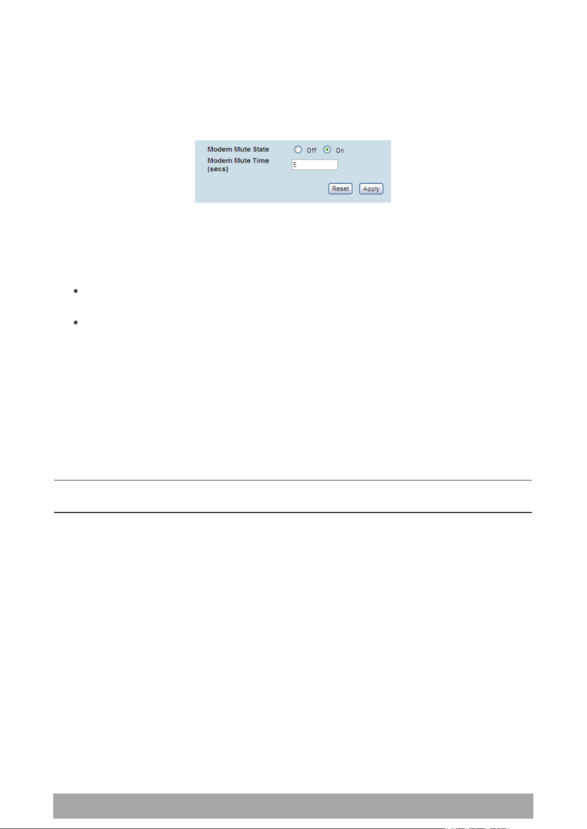
Configuring the Terminal | 73
Aprisa XE User Manual
Modem Mute Mode
The Aprisa XE radio always mutes its interface ports when the modem loses lock.
The Modem Mute feature mutes its interface ports when the modem Reed Solomon forward error
correction capability can no longer correct errors.
This can occur when the signal strength of the RF link reduces to within about 2 dB of the theoretical
sensitivity of the radio or when the radio is operating well above the sensitivity threshold but is in an
environment subject to impulse noise interference on the RF path.
When the mute activates;
On the analog cards, Q4EM, DFXS and DFXO, the audio path mutes and the signalling states go
idle.
On the digital cards, QV24 and HSS, it causes an all ones data pattern to be driven on the RXD
output line and handshake lines such as RTS / CTS to their off states while on the QJET card it
forces the ports to an AIS state.
The Modem Mute feature effectively reduces the radio receiver sensitivity by 2 to 3 dB from its published
values but will prevent errors from corrupting the tributary audio circuits.
Modem Mute Time
The Modem Mute Time determines the time the mute will persist after the last uncorrectable block is
received. This can be set from 0 to 10 seconds in 0.1 second steps.
Note: The Modem Mute feature is only available if the radio modem is Rev D or later. If the radio has a
Rev A, Rev B or Rev C modem, the modem mute functionality is not displayed in SuperVisor.

74 | Configuring the Terminal
Aprisa XE User Manual
Entering Basic Terminal Information
To enter basic terminal information:
Select Link or Local or Remote > Terminal > Basic
Terminal Information
The data entry in these four fields can be up to 40 characters but cannot contain back slashes or double
quotes.
1. Enter the terminal Name. This appears in the Terminal status and menu bar at the top of every page.
2. Enter a unique Terminal ID.
3. Enter the Location of the terminal.
4. Enter a contact name or an email address in Contact Details. The default value is ‘support@4RF.com’.
5. Click Apply to apply changes or Reset to restore the previous configuration.

Configuring the Terminal | 75
Aprisa XE User Manual
Configuring the IP Settings
Select Link or Local or Remote > Terminal > Advanced.
Advanced Terminal Settings
1. Enter the static IP Address for the terminal assigned by your site network administrator using the
standard format xxx.xxx.xxx.xxx. The default IP address is in the range 169.254.50.xx.
2. Enter the Subnet Mask for the terminal using the standard format xxx.xxx.xxx.xxx. The default subnet
mask is 255.255.0.0.
3. Enter the Default Gateway for the terminal, if required, using the standard format xxx.xxx.xxx.xxx
(there is no default gateway set by default.)
4. Enter the IP address of the remote terminal using the standard format xxx.xxx.xxx.xxx (the default IP
address is in the range 169.254.50.xx.)
5. If you are setting up for remote logging (see ‘Setting up for Remote Logging’ on page 255), enter the
Syslog Address and the Syslog Port for the remote terminal.
6. In Time Zone Offset from GMT, select the time zone from the list (optional) .
7. To set the Time to the PC real-time clock, click Now.
8. Click Apply to apply changes or Reset to restore the previous configuration.

76 | Configuring the Terminal
Aprisa XE User Manual
Clock Status
Clock Status Description
Inactive
This clock source is either not configured at all, or is not in current use
Active
This clock source is providing the clocking for the terminal
Holdover
This clock source is nominated as Primary or Secondary but is currently
unavailable.
Setting the Terminal Clocking
To view the terminal clock status:
Select Link or Local or Remote > Terminal > Clocking
The current selected clock source and the current status of the primary and secondary external clocks are
shown:

Configuring the Terminal | 77
Aprisa XE User Manual
Clock Source
Terminal Clocking
External
The terminal is clocked from the nominated interface port selected as
the primary external clock or the secondary external clock.
Internal
The terminal is clocked from the terminal's internal clock.
Link
The terminal is clocked from the RF link.
To select the terminal clock source:
The Clock Source selected for the terminal will be used to clock all interface ports requiring clocking and
send a clocking signal over the RF link.
Select Link or Local or Remote > Terminal > Clocking > Clock Source and select one of the following:
If the terminal Clock Source is set to External, the terminal will automatically clock from the nominated
primary external clock source if that clock source is available.
If the nominated primary external clock source is not available, the terminal will clock from the
nominated secondary external clock source if that clock source is available.
If the nominated secondary external clock source is not available, the terminal will clock from the internal
clock source.
When a nominated external clock source becomes available (primary or secondary), the terminal will then
clock from that clock source.
The terminal at one end of the link must have its clock source set to Internal or External and the terminal
at the other end of the link must have its clock source set to Link.

78 | Configuring the Terminal
Aprisa XE User Manual
To select the interface port for the external clock source (external clock source only):
Select the traffic interface ports nominated as Primary External Clock or Secondary External Clock
sources.
The failure of both External Clock sources results in a major alarm.
To manually override the automatic clock source selection (external clock source only):
Select either Switch to Primary or Switch to Secondary from the drop-down list, and click Apply.

Configuring the Terminal | 79
Aprisa XE User Manual
Setting the Duplexer Parameters
To set the duplexer parameters:
Select Link or Local or Remote > Terminal > Duplexer
Duplexer Parameters
The terminal TX and RX frequencies entered are validated against the duplexer parameters entered on
this page.
A valid high port frequency must be:
(duplexer high port centre frequency + pass band/2 - channel size/2)
and
(duplexer high port centre frequency – pass band/2 + channel size/2)
A valid low port frequency must be:
(duplexer low port centre frequency + pass band/2 - channel size/2)
and
(duplexer low port centre frequency – pass band/2 + channel size/2)
The duplexer parameters are entered in the factory but can be re-entered if the duplexer is changed in
the field. The parameters required are shown on the duplexer label.
1. Enter the duplexer High port centre frequency and Low port centre frequency in MHz.
2. Enter the duplexer Pass band in MHz (the total passband e.g. if the duplexer passband is show as
± 3.5 MHz, the value entered is 7 MHz).
3. Select Transmit High or Transmit Low
Transmit High - the Transmitter is connected to the High Port of the duplexer.
Transmit Low - the Transmitter is connected to the Low Port of the duplexer.
4. Enter the duplexer Serial Number (used for record keeping only).
5. Click Apply to apply changes or Reset to restore the previous configuration.

80 | Configuring the Terminal
Aprisa XE User Manual
Setting the RSSI Alarm Threshold
The threshold (in dB) at which the RSSI alarm activates can be set for each of the modulation types over
the adjustment range of -40 dBm to -110 dBm and the default values are as per the following screen shot.
The alarm threshold has a +1 dB hysteresis for the inactive state.
To set the RSSI alarm threshold:
Select Link or Local or Remote > Alarms > RSSI Thresholds
1. Enter the alarm threshold required for each of the modulation types.
2. Click Apply to apply changes or Reset to restore the previous configuration.

Configuring the Terminal | 81
Aprisa XE User Manual
Configuring the External Alarms
Each terminal has two external alarm inputs and four external alarm outputs, terminated on the ALARM
RJ-45 connector on the terminal front panel.
Each external alarm input can activate the Major / Minor terminal alarm or be mapped to a remote
terminal external alarm output.
The ‘Alarm On When’ (active alarm state) for both inputs can be configured for 'External Source On' or
'External Source Off' (default is External Source On).
Each external alarm output can be triggered by a local terminal Major / Minor alarm or a remote terminal
Major / Minor alarm or either of the remote external alarm inputs.
The ‘Relay Closed When’ for the four outputs can be configured for 'Alarm On' or 'Alarm Off' (default is
Alarm Off).
Configuring the External Alarm Inputs
To configure the External Alarm Inputs:
Select Link or Local or Remote > Alarms > Ext Alarm Inputs
Note: When the MHSB mode is enabled on the terminal, the external alarm input 2 is used for protection
switch control so is not available for user alarms.
The state of the local terminal external alarm input is always sent to the remote terminal and the
external alarm input can be mapped to a remote terminal external alarm output.
Alarms present on a local terminal external alarm input will only be displayed in the remote terminal
Alarm Table / Alarm History if it has been mapped to one of the remote terminal external alarm outputs.

82 | Configuring the Terminal
Aprisa XE User Manual
Display Locally
External Alarm Input Function
No
The external alarm input does not generate an alarm on the
local terminal, does not appear in the ‘Alarm Table’ or ‘Alarm
History’, and shows as grayed out on the ‘Alarm Summary’.
Default
Yes
The external alarm input generates an alarm on the local
terminal, displays in the ‘Alarm Table’ and ‘Alarm History’ and
the ‘Alarm Summary’.
Severity
External Alarm Input Severity
Minor
The external alarm input generates a minor alarm on the local
terminal.
Default
Major
The external alarm input generates a major alarm on the local
terminal.
Alarm On When
External Alarm Input State
External Source On
The alarm is on (alarm active) when a source of voltage is
applied to the external alarm input and current is flowing.
Default
External Source Off
The alarm is on (alarm active) when no source of voltage is
applied to the external alarm input and hence no current is
flowing.
1. Select the Display Locally setting for each alarm input.
2. Select the Severity setting for each alarm input.
This option is only relevant when the ‘Display Locally’ option is set to ‘Yes’.
3. Enter a Description for each alarm input. The default is ‘External Input 1’ / ‘External Input 2’.
4. Select the Alarm On When setting for each alarm input.
5. When you have made your changes, click Apply to apply changes or Reset to restore the previous
configuration.

Configuring the Terminal | 83
Aprisa XE User Manual
Mapping
External Alarm Output Function
None
No external alarm output.
Default
Local Major
The external alarm is present when the local terminal has a
major alarm.
Local Minor
The external alarm is present when the local terminal has a
minor alarm.
Remote Major
The external alarm is present when the remote terminal has a
major alarm.
Remote Minor
The external alarm is present when the remote terminal has a
minor alarm.
Remote Input 1
The external alarm is present when the remote terminal
external alarm input 1 is present.
Remote Input 2
The external alarm is present when the remote terminal
external alarm input 2 is present.
Test Major
External alarm test function – major alarm
This setting will output an alarm on the selected output but it
will not show in the alarm table or on the OK LED of the radio
(it is not a 'real' alarm).
This alarm test will clear if radio reboots.
Test Minor
External alarm test function – minor alarm
This setting will output an alarm on the selected output but it
will not show in the alarm table or on the OK LED of the radio
(it is not a 'real' alarm).
This alarm test will clear if radio reboots.
Configuring the External Alarm Outputs
To configure the External Alarm Outputs:
Select Link or Local or Remote > Alarms > Ext Alarm Outputs
Note: When the MHSB mode is enabled on the terminal, the external alarm output 4 is used for protection
switch control so is not available for user alarms.
1. Select the Mapping required for each alarm output.

84 | Configuring the Terminal
Aprisa XE User Manual
Relay closed when
External Alarm Output State
Alarm on
When the external alarm output relay contact is closed, the
alarm is on (alarm active).
Default
Alarm off
When the external alarm output relay contact is closed, the
alarm is off (alarm inactive).
2. Select the Relay closed when setting for the four alarm outputs.
3. When you have made your changes, click Apply to apply changes or Reset to restore the previous
configuration.

Configuring the Terminal | 85
Aprisa XE User Manual
Configuring SNMP Settings
In addition to web-based management (SuperVisor), the terminal can also be managed using the Simple
Network Management Protocol (SNMP). MIB files are supplied, and these can be used by a dedicated SNMP
Manager, such as Castle Rock's SNMPc (www.castlerock.com), to access most of the terminal's configurable
parameters.
However, it is recommended that SNMP is only used for status and alarm monitoring of your entire
network. SuperVisor is the best means to configure individual terminals.
For communication between the SNMP manager and the terminal, Access Controls, Trap Destinations, and
Community strings must be set up as described in the following sections.
A SNMP Access Control is the IP address of the terminal used by an SNMP manager or any other SNMP
device to access the terminal. Entering an IP address of ‘Any’ (not case sensitive) or * will allow any IP
address access to the terminal. A community string is sent with the IP address for security.
Commands are sent from the SNMP manager to the terminal to read or configure parameters of the
terminal e.g. setting of interface parameters.
A SNMP Trap Destination is the IP address of a station running an SNMP manager. A community string is
sent with the IP address for security.
Events are sent from the terminal to the SNMP manager e.g. alarm events.
A SNMP Community String is used to protect against unauthorized access (similar to a password). The
SNMP agent (terminal or SNMP manager) will check the community string before performing the task
requested in the SNMP message . Trap Destinations and Access Controls both use community strings for
protection.
To configure Trap Destinations and Access Controls:
Select Local > Maintenance > SNMP > SNMP Settings
Note: SNMP Settings can only be setup on the local terminal.

86 | Configuring the Terminal
Aprisa XE User Manual
SNMP Access Controls
To add an access control:
1. Click on the ‘Add Read Only’ button to enter a Read Only access control or click on the ‘Add
Read/Write’ button to enter a Read/Write access control.
2. Enter the IP address of each SNMP manager allowed access to the terminal (read/write access control
shown). The IP address entered must be a valid dot delimited IP address.
Entering an IP address of ‘Any’ or * will allow any IP address access to the terminal.
3. Enter the community string for the access control.
The Community string is usually different for Read Only and Read/Write operations.
There is no default 'public' community string for an access control, but a 'public' community string can
be entered which will have full MIB access, including the 4RF MIB.
4. Click Add.
To delete an access control:
1. Select the access control you want to delete and click Delete.
2. Click OK to delete the access control or Cancel to abort the delete.

Configuring the Terminal | 87
Aprisa XE User Manual
SNMP Trap Destinations
To add a trap destination:
1. Click on the ‘Add SNMPv1’ button to enter a SNMPv1 trap destination or click on the ‘Add SNMPv2c’
button to enter a SNMPv2c trap destination.
The differences between SNMPv1 and SNMPv2c are concerned with the protocol operations that can be
performed. Selection of SNMPv1 and SNMPv2c must match the setup of the SNMP manager.
2. Enter the IP address of the server to which you want SNMP traps sent (SNMPv1 trap destination
shown). The IP address entered must be a valid dot delimited IP address.
3. Enter the community string for the trap destination.
There is no default 'public' community string for a trap destination, but a 'public' community string can
be entered.
4. Click Add.
To delete a trap destination:
1. Select the trap destination you want to delete and click Delete.
2. Click OK to delete the trap destination or Cancel to abort the delete.

88 | Configuring the Terminal
Aprisa XE User Manual
Viewing the SNMP Traps
Any event or alarm in the SNMP objects list can be easily viewed. This also enables you to verify, if
required, that SNMP traps are being sent.
Select Local > Maintenance > SNMP > View Traps.
Viewing the SNMP MIB Details
This is useful to see what MIB (Management Information Base) objects the terminal supports.
Select Link or Local or Remote > Maintenance > SNMP > View MIB Details.

Configuring the Terminal | 89
Aprisa XE User Manual
Saving the Terminal's Configuration
Note: To save cross connection configurations, see page 155.
To save a configuration:
1. Ensure you are logged in with either 'modify' or 'admin' privileges.
2. Select Local > Maintenance > Config Files > Save MIB.
3. Select the 'Save to disk' option in the dialog box that appears.
4. In the next dialog box that appears, navigate to the directory where you want to save the file, enter a
suitable filename, and then click Save (The default name for this file is backupForm).
Note 1: If this dialog box does not appear, change your Internet security settings to allow downloads.
You may also need to check your default download location.
Note 2: Pop-ups must be enabled on you PC for this function to work (see ‘PC Settings for SuperVisor’
on page 50).
To load a configuration into a terminal:
Important: Only load a saved configuration file to another terminal that has exactly the same
configuration (RF variant and interface cards).
1. Ensure you are logged in with either 'modify' or 'admin' privileges.
2. Select Local or Remote > Maintenance > Config Files > Load MIB.
3. Click Browse and then navigate to the file and select it.
4. Click Upload to load the configuration file into the terminal.


Configuring the Traffic Interfaces | 91
Aprisa XE User Manual
9. Configuring the Traffic Interfaces
Important: When configuring a link, it is important that you configure the remote terminal first as the
new configuration may break the management connection to the remote terminal.
Once the remote terminal has been configured, the local terminal should be configured to match the
remote terminal.
Viewing a Summary of the Interfaces
To view a summary of the interfaces fitted:
Select Link or Local or Remote > Interface > Interface Summary.
The Interface Summary page shows:
The interface type for each slot that has been configured with the capacity used by each port.
Total Capacity. The total capacity of the radio link.
Ethernet Capacity. The capacity allocated to the Ethernet traffic over the radio link. This includes
the user and management capacity assigned.
Management Capacity. The capacity allocated to the management conduit over ethernet.
Radio Capacity. The percentage of the total capacity of the radio link that has been allocated to
traffic interfaces.
Drop and insert capacity. The percentage of the total drop and insert capacity used for local drop
and insert cross connections. The total drop and insert capacity is 65536 kbit/s minus the assigned
radio link capacity.
Some interfaces also require extra bandwidth to be allocated to transport signalling, such as CTS / DTR
handshaking or E&M signals. The cross connections application automatically allocates capacity for
signalling when it is needed.

92 | Configuring the Traffic Interfaces
Aprisa XE User Manual
Configuring the Traffic Interfaces
Important: Before you can configure the traffic interfaces, the interface cards must be already installed
(see ‘Installing Interface Cards’ on page 235).
Configuring each traffic interface involves the following steps (specific instructions for each interface card
follow this page).
First, specify the port settings for the Remote terminal:
1. Select Remote > Interface > Interface Summary, select the interface card and click Configure
Interface.
2. Select the port you want to configure and modify the settings, as necessary.
3. Click Apply to save the changes you have made.
Now specify the port settings for the Local terminal:
1. Select Local > Interface > Interface Summary, select the interface card and click Configure Interface.
2. Select the port you want to configure and modify the settings, as necessary.
3. Click Apply to save the changes you have made.
Once you have done this, you will need to configure the traffic cross-connects (see ‘Configuring the traffic
cross connections’ on page 145) for each interface card.

Configuring the Traffic Interfaces | 93
Aprisa XE User Manual
Ethernet Switch
In the default mode, the Ethernet switch passes IP packets (up to 1522 bytes) as it receives them.
However, using SuperVisor you can configure VLAN, QoS and port speed settings to improve how IP traffic
is managed.
This is useful for operators who use virtual networks to segment different groups of users or different
types of traffic in their network. These groups can be maintained across the radio link thus ensuring users
in one virtual network cannot access data in other virtual networks.
The switch also has a high-speed address lookup engine, supporting up to 2048 preferential MAC addresses
as well as automatic learning and aging. Traffic is filtered through this table and only traffic destined for
the remote end is sent across the link improving bandwidth efficiency.
Note: You need ‘modify’ or ‘admin’ privileges to configure the Ethernet for VLAN and Quality of Service
(QoS).
VLAN tagging
By default, all user and management traffic is allocated the same VLAN across the link.
Alternatively, you can assign each of the four Ethernet ports to a VLAN. Each VLAN can be configured to
carry user traffic, or user traffic and radio management traffic. The VLAN tagging conforms to IEEE
802.1Q standard.

94 | Configuring the Traffic Interfaces
Aprisa XE User Manual
Configuring the Ethernet switch for VLAN tagging
1. Select Link or Local or Remote > Interface > Ethernet Settings.
Note: Always configure the remote terminal before the local terminal
2. In the Quick Links box at the bottom of the page, click Ethernet General Settings.
3. From Ethernet Grouping drop-down list select 'Enabled' ('Disabled' is the default setting; Ethernet
traffic is not segregated).
Important: Changing this setting will disrupt Ethernet traffic.
4. Click Apply to apply changes or Reset to restore the previous configuration.
You now need to select the VLAN groups for each of the four Ethernet ports.

Configuring the Traffic Interfaces | 95
Aprisa XE User Manual
Specifying the VLAN ID for the Ethernet Ports
Each Ethernet port can be configured with one of five VLAN IDs. You can configure each of the physical
ports, numbered 1 to 4 with a VLAN ID (numbered User1 to User4 and User+Mgmt).
These VLAN IDs are applied at the ingress port and only used internally across the link. The VLAN ID is
removed when traffic exits the switch at the egress port. Data entering the Ethernet switch on ports 1 to 4
or the internal management port can only exit on ports that are associated with the same VLAN ID as the
ingress port.
For example, the physical RJ-45 port 1 may be on VLAN 3 at the local end, but at the remote end, the
physical RJ-45 port 4 may be associated with VLAN 3. Traffic entering the local end on port 1 will exit the
remote end on port 4.
To allow the radio link to transport traffic using existing VLAN ID information, the radio adds an extra
VLAN ID over the top of an existing VLAN ID (double-tagging). This extra VLAN ID is added at the ingress
port and removed at the egress port. This adds 4 bytes to the packet and the maximum packet size
supported by the radio is 1526 bytes.
Note 1: Tagged flows can only have one port per VLAN ID on each terminal.
Note 2: The ethernet switch only supports packets up to 1522 bytes in size at the ingress port.
1. Select Link or Local or Remote > Interface > Ethernet Settings.
Note: Always configure the remote terminal before the local terminal
2. In the Quick Links box at the bottom of the page, select the port you want to configure:
3. The Ethernet Port Settings page appears for the port you selected:
4. From the Ethernet Group drop-down list, select the VLAN group to which you want this port to belong.
Important: To access radio management traffic, you need to allocate one of the VLANs to ‘User and
Management’. It is strongly recommended that you indicate which port or group of ports is associated
to the management traffic first.
5. Click Apply.
6. Repeat steps 1-4 for the Ethernet switch in the other terminal in the link.

96 | Configuring the Traffic Interfaces
Aprisa XE User Manual
Quality of Service
Quality of Service (QoS) enables network operators to classify traffic passing through the Ethernet switch
into prioritized flows.
Each port can have a priority tag set at the ingress port, or it can be read directly from the Ethernet
traffic. When read directly from the Ethernet traffic, the following fields are used to determine the
traffic’s QoS priority.
The IEEE 802.1p Priority information in the IEEE 802.3ac Tag.
The IPv4 Type of Service field.
The IPv6 Traffic Class field.
You can select one of two queuing methods:
IEEE 802.1p standard method
Cisco-proprietary method
The queuing method determines how the traffic is prioritized.
Each port has four egress queues (queues 0-3) of differing priorities. Queue 0 is the lowest priority and
Queue 3 is the highest priority.
Configuring the Ethernet Switch for QoS
1. Select Link or Local or Remote > Interface > Ethernet Settings.
2. In the Quick Links box at the bottom of the page, click Ethernet General Settings.
The Ethernet General Settings page:
3. Leave Ethernet Grouping set to 'Disabled' (unless you want to enable VLAN tagging).

Configuring the Traffic Interfaces | 97
Aprisa XE User Manual
Queue
Priority
Number of packets transmitted
Queue 3
Highest Priority
8 packets
Queue 2
4 packets
Queue 1
2 packets
Queue 0
Lowest Priority
1 packets
Output Queue
Priority
Traffic Type
Cisco
Priority Queuing
IEEE 802.1D
Priority Queuing
0 (default)
Best Effort 0 1
1
Background 0 0
2
Spare 1 0
3
Excellent Effort
1
1
4
Controlled Load
2
2
5
‘Video’ < 100ms latency and jitter
2
2
6
‘Video’ < 10ms latency and jitter
3
3
7
Network Control
3
3
4. Select the Priority Queue Scheduling.
There are two methods for transmitting the Ethernet traffic queues across the link:
Strict: the queue is transmitted based on the priority. The first queue transmitted is the highest
priority queue and the terminal will not transmit any other traffic from any other queue until the
highest priority queue is empty. Then the next highest priority queue is transmitted, and so on.
Weighted (default): each of the queues will transmit a number of packets based on a weighting.
The following table shows how the weighting is applied to each queue.
5. Select the IEEE 802.1 Priority Queue Mapping.
This determines the standard (or scheme) used for prioritizing traffic into one of four queues
numbered 0 to 3 (3 being the highest priority queue).
There are two possible methods for queuing the ethernet traffic. One is based on the IEEE 802.1D
standard (which is the default setting), and the other is based on the Cisco-proprietary method.
The following table shows how traffic is queued using the two methods:

98 | Configuring the Traffic Interfaces
Aprisa XE User Manual
Configuring the Ethernet Ports for QoS
Each Ethernet port can be configured for Ingress Rates and Priority queues.
To configure the Ethernet ports for QoS:
1. Select Link or Local or Remote > Interface > Ethernet Settings.
2. Select the port you want to configure and click Port Configuration.
 Loading...