

Page 1
Page 2

VIGIL Copyright ©2014 3xLOGIC, Inc. All rights reserved.
3xLOGIC Inc.
6510 West 91st Avenue
Westminster, CO 80031
USA
Disclaimer
Information in this document is subject to change without notice and does not represent a commitment on the part of 3xLOGIC Inc. The software and/or databases described in this document are furnished under a license agreement or nondisclosure agreement. They may be used or copied only in accordance with the
terms of the agreement. It is against the law to copy the software on any medium except as specifically allowed in the license or nondisclosure agreement. The
purchaser may make one copy of the software for backup purposes. No part of this manual and/or databases may be reproduced or transmitted in any form or
by any means, electronic or mechanical, including (but not limited to) photocopying, recording, or information storage and retrieval systems, for any purpose
other than the purchaser's personal use, without the express written permission of 3xLOGIC Inc.
3xLOGIC, VIGIL and AZTECH are trademarks of 3xLOGIC, Inc.
Other trademarks and trade names may be used in this document to refer to either the entities claiming the marks and names or their products. 3xLOGIC Inc. disclaim any proprietary interest in trademarks and trade names other than their own.
-2-
©2014 3xLOGIC Inc. | VIGIL Server - User Guide
Page 3

Table of Contents
1 Introduction 1
2 Software Features 2
3 Main Screen 3
Icon Toolbar: 3
Main Menu Toolbar: 4
3.1 Live Viewer 6
3.2 Camera Layout and Quick Access 7
3.3 TV Output Switch 8
3.4 Live Viewer Display Controls 9
3.5 Alarms and Relays 10
3.6 Media Drive Information 10
3.7 PTZ Camera Controls 11
3.8 Live POS / ATM Data 14
4 Searching 15
4.1 Searching Video 16
4.1.1 Video Search Results 17
Visual Display 17
Tabular Display 17
4.2 Searching POS/ATM Data 18
4.2.1 Search for Line Items 18
4.2.2 Search for Transaction 19
4.3 Custom Search 20
4.4 Video Playback 21
4.4.1 Controlling Playback Video with Digital PTZ: 22
4.4.2 Camera Right-click Menu: 22
4.4.3 Playback Buttons: 22
4.5 Multi-Screen Playback 23
4.6 Advanced Features 24
4.6.1 Smart Search 24
4.6.2 Zoom 25
-i-
4.6.3 Adjust Image 25
4.6.4 Markers 26
4.6.5 Audio Playback 26
4.7 Authenticating Recorded Video 27
4.8 On-Screen Display - POS/ATM Data 28
©2014 3xLOGIC Inc. | VIGIL Server - User Guide
Page 4

5 Exporting 29
5.1 Exporting, Printing, or Emailing Images 29
5.2 Exporting Video 30
5.3 Exporting Audio 31
5.4 Export File Browser 32
5.5 Alarms 33
5.6 Preview Alarms 34
5.7 Suppress Alarms 34
5.8 Search Alarms 35
5.9 Exporting with VIGIL Archive 36
6 Reports 37
6.1 Client Connections 37
6.2 Network Log Analyzer 37
6.3 Audit Log Analyzer 37
7 Video and Audio Recorder Controls 38
7.1 Video Recorder Controls 38
7.2 Live Audio Settings 39
7.3 Audio Live/Recorder Controls 40
7.4 Chat 40
8 Settings – Camera Setup Tab 41
8.1 Camera Setup Tab - Camera Settings 42
8.1.1 Advanced Settings 42
8.1.2 Push Still Shot to Server 43
8.2 CODEC Settings 44
8.2.1 AZTECH™ CODEC Settings 46
8.2.2 MPEG4 CODEC Settings 47
8.2.3 Hardware CODEC Settings 47
8.3 Network Camera Settings 48
8.3.1 Network Camera Type - VIGIL Server 50
ONVIF and PSIA Network Camera Types 50
ONVIF Device Manager 51
Configuring Imaging and Stream Settings in the ONVIF Device Manager 51
Saving To VIGIL 52
Multiple Cameras Stitched Together Into One Image 52
USB Camera 52
8.4 Recording Mode Tab 53
8.4.1 Recording Modes 53
©2014 3xLOGIC Inc. | VIGIL Server - User Guide -ii-
Page 5

8.4.2 Scheduled Recording 54
8.4.3 Motion Recording Settings 55
8.4.4 Video Motion Alarm 56
8.4.5 Video Motion Alarm Advanced Settings 57
General Tab 57
Schedule 57
Output Relay 57
Post Motion Record 57
Notifications Tab 57
Local Notification Settings 57
Email Notification Settings 58
8.5 Camera Control Tab 59
8.5.1 Advanced Settings 59
During Alarm 60
After Alarm 60
Control Interface 60
8.6 Video Loss Tab 61
8.6.1 Video Loss Mode 61
8.6.2 Video Loss Trigger 61
8.6.3 Video Loss Email Notification 61
8.7 Audio Tab 62
8.8 Live Overlay Tab 62
9 Settings - Video Analytics Tab 63
9.1 Video Analytics Calibration 64
9.1.1 General 65
9.1.2 Perspective Settings 66
Overhead Camera 66
Perspective Camera 66
9.1.3 Object Type 67
9.1.4 Mask Settings 67
9.1.5 Engine Settings 68
Customized Predefine Mode 68
9.1.6 Display Options 70
Obstacle Settings 71
9.1.7 Meta Settings 72
-iii-
9.1.8 Preview 72
Options 72
Display Layer 72
9.1.9 Kinect™ Settings 74
9.2 Video Analytics Rules 75
9.2.1 People Counting 76
©2014 3xLOGIC Inc. | VIGIL Server - User Guide
Page 6

Camera Placement 76
Rule Settings Tab 76
Queue Region Settings Tab 77
People Counting Single Tripwire 78
General Tab 78
Wire Settings Tab 79
Alert Settings Tab 79
Rule Settings Tab 80
Queue Region Settings Tab 81
People Counting Multiple Tripwire 82
Wire Settings Tab 82
9.2.2 Transaction with No Customer Present 83
Customer Not Present Rule 83
General Tab 83
Region Settings Tab 84
Alert Settings Tab 84
Rule Settings Tab 85
V-POS Exceptions 85
9.2.3 Queue Analytics 86
Camera Placement 86
Time in Queue Rule 86
General Tab 86
Region Settings Tab 87
Alert Settings Tab 87
Alarm Settings Tab 87
Time in Queue, Directional Exit Rule 88
General Tab 88
Rule Settings Tab 89
Queue Region Settings Tab 90
Number of People in Queue Rule Settings 91
General Tab 91
Region Settings Tab 91
10 Settings - Server Settings Tab 92
10.1 - Server Settings Tab - Basic Settings 92
10.1.1 Site Name 92
10.1.2 Interface 92
10.1.3 Offsite Backup on Alarm 92
10.1.4 SMTP Server 93
10.1.5 Central SQL Database 93
10.2 General Tab 94
10.2.1 User Audit 96
User Audit Configuration 96
Performance Criteria 96
Usage Performance Indicator 96
©2014 3xLOGIC Inc. | VIGIL Server - User Guide -iv-
Page 7

User Audit Report 97
Report Types 97
Sample Report 97
Example Usage Summary Report 98
User Performance Report 98
10.3 Startup Tab 99
10.4 Live Tab 100
10.5 Search Tab 101
10.6 Cameras Tab 101
10.7 Clients Tab 102
10.8 Sequence Tab 102
10.9 Hardware Tab 103
10.10 VIGIL Connect Tab 105
10.11 Proxy Tab 107
10.12 Help Menu Tab 107
11 Settings - Media Drives Tab 108
11.1 Video Storage Drives 109
11.2 Using a Virtual File Server for Video Storage 110
Add a Network Drive to VIGIL Server 110
11.3 Data Partitioning for Video and POS/ATM Alarm Video Footage 111
11.4 Alternate Video Storage Drives 111
11.5 Export Destinations 112
12 Settings - COM Ports Tab 113
13 Settings - User and Group Management Tab 114
13.1 Users Tab 114
13.2 Groups Tab 115
14 Settings - Relays/Alarms Tab 116
14.1 Input 116
14.1.1 Input Number 116
14.1.2 Settings Tab 116
14.2 Notification Settings Tab 117
-v-
14.2.1 Email Notification 117
14.2.2 Output Relay 117
14.2.3 Notification Settings 117
14.3 Remote Client Retry Settings 118
14.4 Output Relay Settings 118
14.4.1 Relay Override 118
©2014 3xLOGIC Inc. | VIGIL Server - User Guide
Page 8

15 Settings - Data Tab 119
15.1 POS/ATM Connection Settings 119
15.1.1 POS/ATM Settings 119
Priority Camera Settings 119
15.1.2 Connection Settings 119
POS Logging Settings 120
15.1.3 POS/ATM Alarm Settings 120
Filter Settings... 120
15.2 General Settings Tab 121
Live / Playback Settings 121
Data Storage Settings 121
POS Search History 121
15.3 Email Settings Tab 122
15.4 Ignore Fields Tab 123
15.5 External POS/ATM Data Tab 123
15.6 External Data Interface Tab 124
16 Settings - Audio Tab 125
16.1 Audio Recording Device Settings 125
16.2 Audio Talk Device Settings 126
16.3 Live Audio Settings 126
16.4 Audio Storage Drives 126
16.5 Audio Talk / Chat 126
17 DV Player 127
18 Registration 129
19 Language Switcher 130
20 VIGIL Server System Database Utility 131
20.1 Drive Management Tab 132
20.2 Data Management Tab 133
Purge Data 133
Rebuild Database 133
Reset Initial Footage Date / POS ATM Database 133
20.3 Database Management Tab 134
Settings 134
Backup/Restore Database 134
Repair Database 134
20.4 Database Settings Tab 135
Local Database Administrator Password 135
©2014 3xLOGIC Inc. | VIGIL Server - User Guide -vi-
Page 9
TCP Port 135
Central SQL Database 135
Local Database Memory Usage 136
21 Settings Utility 137
22 VIGIL Server Backup Utility 138
23 Contact Information 139
-vii-
©2014 3xLOGIC Inc. | VIGIL Server - User Guide
Page 10
1 Introduction
This guide describes the operation of 3xLOGIC’s VIGIL Server Software (VIGIL Server).
VIGIL Server is cutting edge digital video recording software with an abundance of powerful features. Sever's enhanced video analytics, multiple display methods, micro-management style settings and POS/ATM capability are just a few examples of the features
that can help to improve the efficiency and stability of your business. Its intuitive design provides ease of use for the most basic user
while providing virtually unlimited flexibility for the advanced. VIGIL Server has also been engineered to be securely and seamlessly
accessible via 3xLOGIC's remote VIGIL Client software, giving you access to your Server from single or multiple remote location(s).
The following guide will familiarize you with the software interface and its many features but do not hesitate to contact us with any
questions, concerns or suggestionsSee "Contact Information" on page 139
Welcome to 3xLOGIC's VIGIL Server.
Disclaimer: *T his applicationhas been optimized for usewithWindows XP and Windows 7. 3xLOGIC does not actively support other operating systems. Installing thisapplicationon operating systems other than the those mentioned
above m ay have undesirable consequences.
©2014 3xLOGIC Inc. | VIGIL Server - User Guide -1-
Page 11
2 Software Features
This section describes some of the features of VIGIL Server.
Feature Details
Individual Camera Set-
tings
Configurable CODEC Set-
tings
IP Camera Support VIGIL Server supports up to 32 IP hi-resolution cameras without the need for an installed capture card.
Live Viewer View live footage as it records for up to 32 video feeds.
Built-in Playback Scan previously recorded footage using the built-in video player.
Full Video Search
Capabilities
Exporting/Saving Video
and Images
Configure each camera independently: brightness, contrast, sharpness, hue, resolutions, and more.
Change CODEC settings for each camera such as compression, quality, noise reduction, and more.
Retrieve a list of stored footage for specified cameras from a start date/time to an end date/time and
a variety of other search criteria.
Powerful export capabilities enable you to save video footage in AVI or Authentic Video (MJPG) formats. Save still shots in JPEG or BMP formats.
-2-
©2014 3xLOGIC Inc. | VIGIL Server - User Guide
Page 12
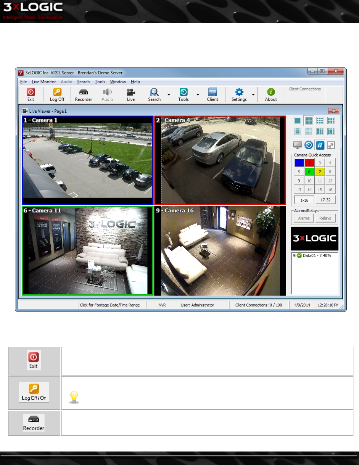
3 Main Screen
This is the main screen window that is displayed when VIGIL Server has finished loading. The program will automatically load at Windows start-up, log on and open the Live Viewer window. These options can be changed in the settings, if desired.
Icon Toolbar:
This table is a quick listing of the main toolbar buttons and their usage. Detail of each corresponding window is outlined in later sections.
Exits the VIGIL Server program. Click Yes in the Exit Confirmation window to exit VIGIL Server. This will
cause VIGIL Server to stop recording video footage.
Logs off/on the current user. Login credentials will be required when logging in.
Note: VIGIL Server will continue to record video footage while the user is logged off.
Opens the Recorder Controls window.
©2014 3xLOGIC Inc. | VIGIL Server - User Guide -3-
Page 13
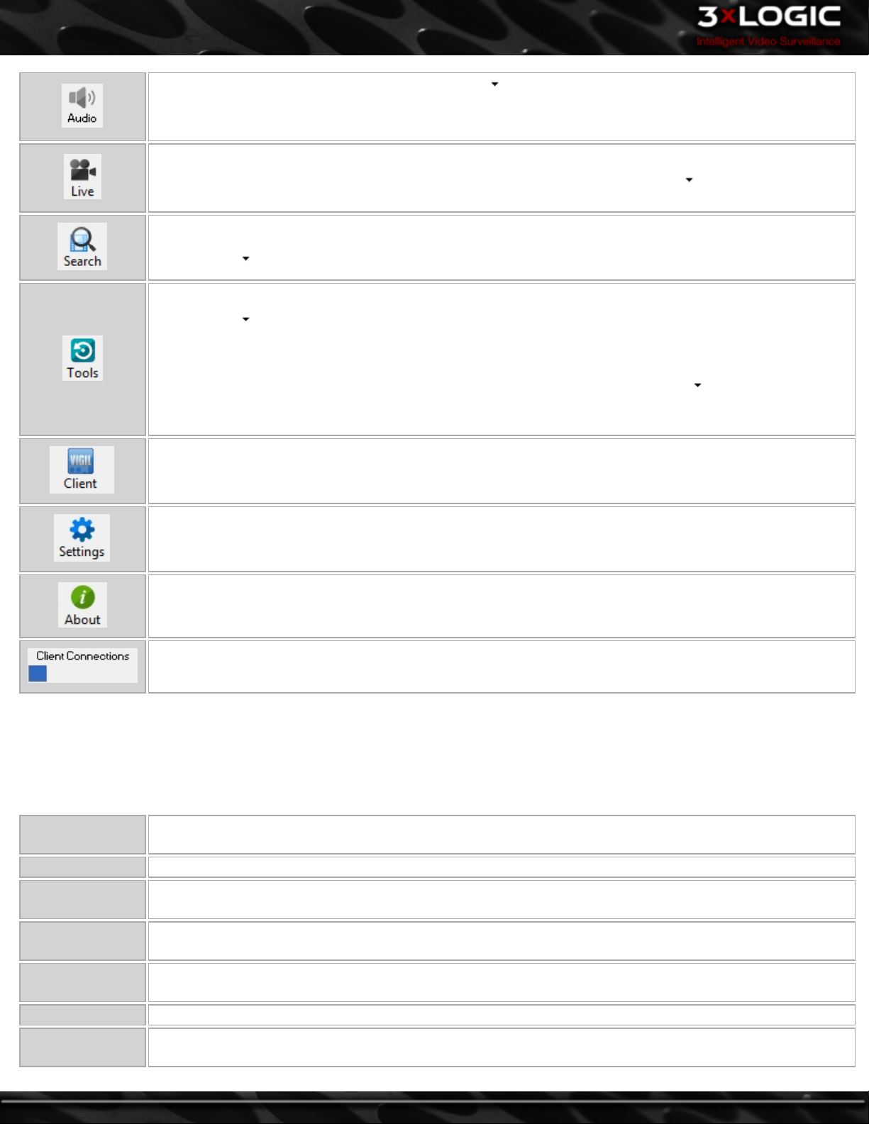
Opens the Live Audio Settings window. Clicking the button opens the context menu from which the Audio
Recorder Controls window can be opened.
The button changes its icon and function to the last used audio window.
Opens the Live Viewer window.
If Hardware Rendering has been enabled and is supported by the capture card, the button can be clicked.
This opens a context menu allowing selection of either Software Rendered Cams or Real Time Cams.
Opens the Search window.
Clicking the button opens the context menu which allows you to open the Custom Search window.
Resets the windows to their default positions.
Clicking the button opens the context menu which allows you to open Live POS/ATM Data, Alarms,
Export File Browser, Reset Windows Positions, Analog Multiplexer Setup, Sequence, Client Connections, and
User Audit.
The button changes its icon and function to the last used tool item. For example, if is clicked and Live
POS Data is selected, not only would it open the Live POS Data window, but it would also replace the reset
icon with the icon for the Live POS Data window.
Launches VIGIL Client.
Opens the Settings window. This is the main configuration page for VIGIL Server.
Opens the About 3xLOGIC VIGIL Server System window that contains information such as the trial period
remaining, registration information and the software version (including IP Camera and POS .dll file versions).
A basic graph that lets you know how many client connections are open to VIGIL Server. Hover the mouse cursor over this section to view the exact number or click to open the Client Connections window.
Main Menu Toolbar:
Main menu options include window viewing features via the Windows menu item and access to the User Guide or Hardware Information via the Help menu item. Additionally, the Tools menu in the main VIGIL Server window expands on the functions in the icon
toolbar.
The following features are accessible by clicking on the Tools menu item:
Live POS/ATM
Data
Alarms Lists alarm events and thumbnails; allows you to replay footage from the time of the event.
Export File
Browser
Reset Window
Positions
Analog Mul-
tiplexer Setup
Sequence Enables and disables a configured camera Sequence.
Client Con-
nections
Displays a live viewer of received data. This data can come from any supported data source such as: Point of
Sale, ATM or Access Control.
Displays a thumbnail browser interface to the export destinations.
Resets all windows to their original sizes and locations.
Opens the Analog Out Multiplexer window.
Lists client systems currently connected to the VIGIL Server.
-4-
©2014 3xLOGIC Inc. | VIGIL Server - User Guide
Page 14
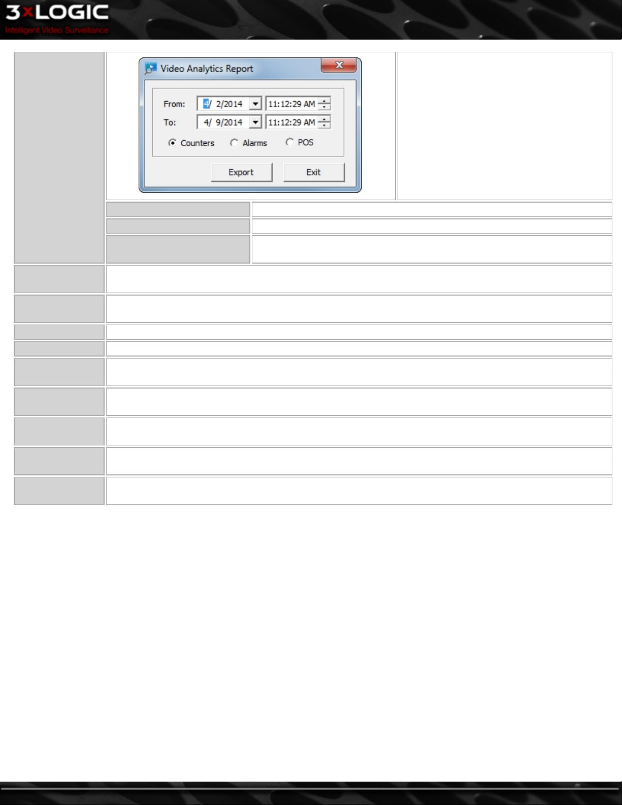
Video Analytics
Report
Counters For rules where data is counted, entries with count logs are exported.
Alarms For rules where alarm conditions are configured, the alarms are exported.
POS
User Audit Report
VIGIL Archive
Recorder Opens the Recorder Controls window.
Settings Opens the Settings window.
Network Log
Analyzer
Audit Log
Analyzer
V-POS
Update…
Register VIGIL
Server
Opens the User Audit Report window where configured usage monitoring can be reviewed. To use the User
Audit features, itmust be configured in the settings window.
Open the VIGIL Archive export window. Please refer to the VIGIL Archive users guide for more information on
VIGIL Archive. See "Exporting with VIGIL Archive" on page 36
Opens the Network Log Analyzer, used to display history of functions performed by users over the network.
Opens the Audit Log Analyzer, used to display a log of any information, warnings or errors from VIGIL Server.
Provides a quick way to load the application if the V-POS software program is installed. It is especially useful
if VIGIL is configured for Kiosk mode where the Windows Start menu is disabled.
Opens the Local Update Utility that provides a small program to perform software updates for VIGIL Server
applications.
Opens the Registration window to allow you to register the VIGIL software.
Opens a window where the user selects a
time range for a Video Analytics Counters,
Alarms or POS report. When the range has
been selected, click the Export button to
save the report in CSV format to a Windows
destination. The report will show results
recorded for certain types of video analytics
rules including the camera number, rule
type, time, and object count.
For rules where register regions are configured, the register counts are
exported.
©2014 3xLOGIC Inc. | VIGIL Server - User Guide -5-
Page 15
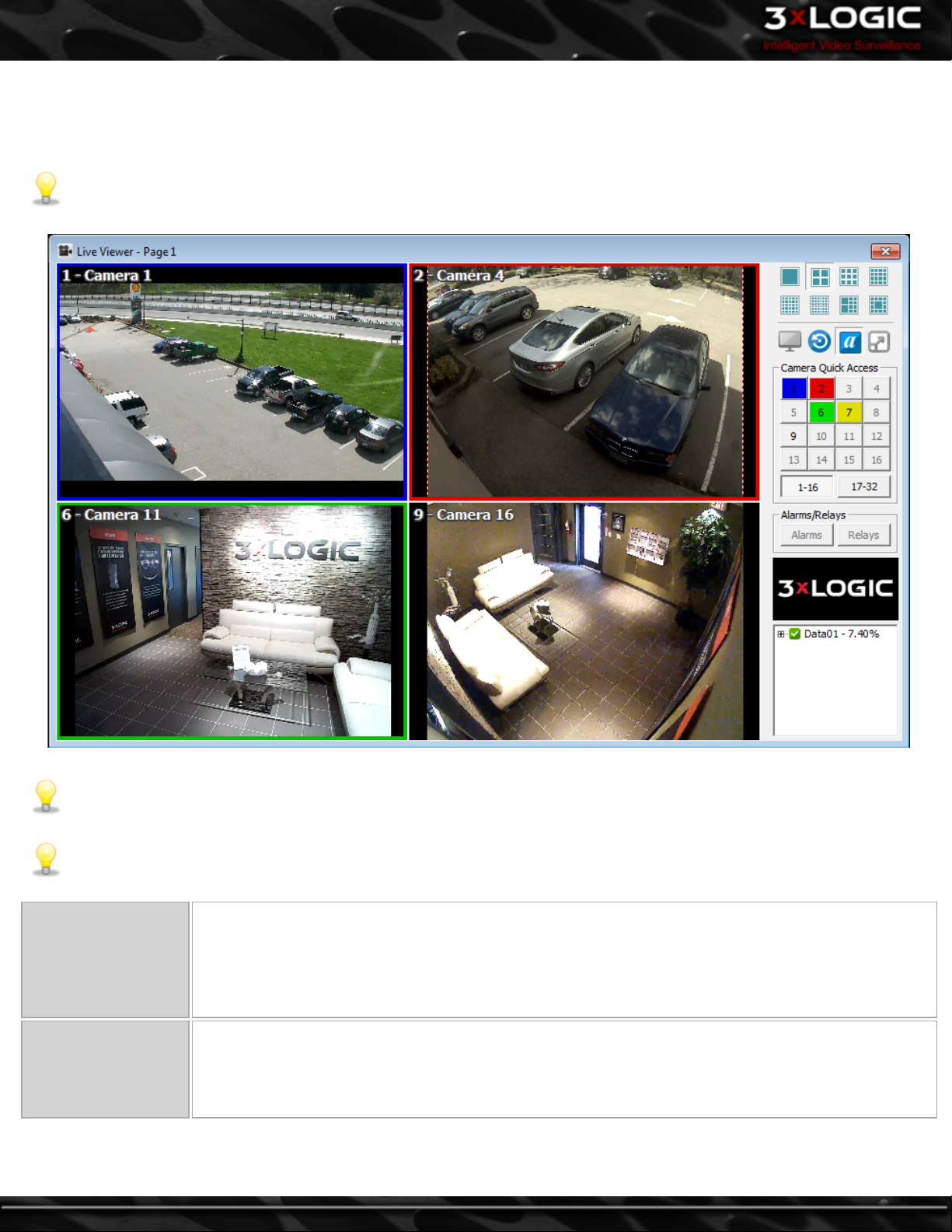
3.1 Live Viewer
The Live Viewer window will open automatically once the program has loaded. If Auto Logon is disabled in the settings, you must log
on before the Live Viewer window is opened.
Note: The Live Viewer is a CPU and Graphics Adapter intensive function.
Note: The Live Viewer window can be in either Software Rendered mode or Hardware Rendered mode. If your capture card
supports Hardware Rendered mode, it can be enabled by going to Settings| VIGIL Server Settings tab | Live tab and select-
ing the Live Viewer mode with the available radio button.
Note: Appearance of the Live Viewer may vary depending on installed capture card, rendering mode, etc.
Software Rendered
Hardware Rendered
-6-
l Requires more CPU usage.
l Camera display speed depends on CPU and video card abilities
l Able to display up to 32 camera feeds.
l Able to display network camera feeds.
l Information overlays such as recording status and video analytics data.
l Zooming displayed camera feeds and other available camera manipulation features.
l Able to display up to 32 camera analog feeds.
l Less CPU usage.
l Able to display network camera feeds.
l Cannot display information overlays.
l Cannot zoom displayed camera feeds.
©2014 3xLOGIC Inc. | VIGIL Server - User Guide
Page 16
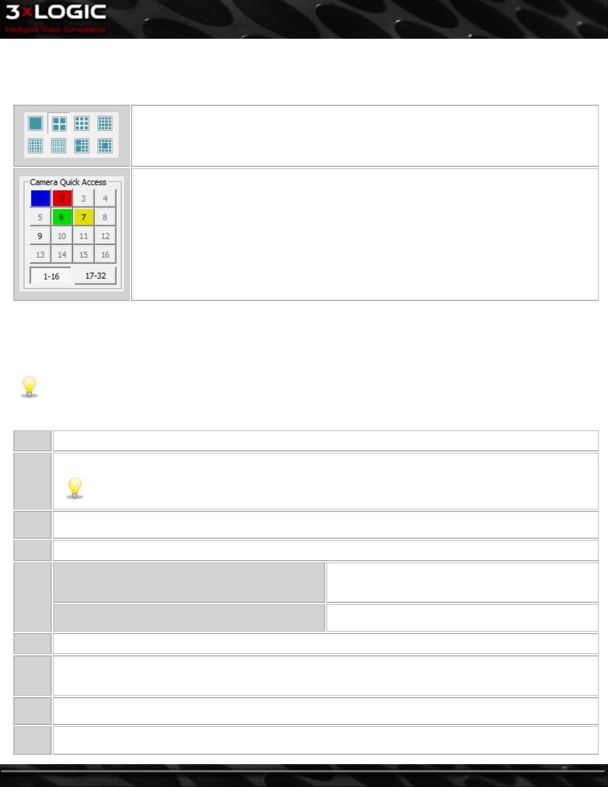
3.2 Camera Layout and Quick Access
Use the buttons in the top section of the Live Viewer side toolbar to select the viewing style. If you have more cameras enabled than
can be displayed by the current view settings, you can right-click on the layout icon and select a page of cameras to display.
Software Rendered mode for 32 channel systems has these available viewing options:
Single view mode (1 camera), 2 x 2 mode (4 cameras), 3 x 3 (9 cameras), 4 x 4 (16 cameras), 5 x 5 (25
cameras), 6 x 6 (36 cameras). 2 large w/8 small cameras, 1 large w/12 small cameras.
Hardware Rendered mode viewing options vary based on the system model.
To quickly select a camera for Single Live View display mode, click its corresponding number in the
Camera Quick Access pad. Camera Quick Access also provides a simple way to check the recording
status of each camera, which is communicated through color:
l Green: Constant recording mode and is recording.
l Blue: Motion recording mode and is recording (motion detected).
l Red: Alarm recording mode and is recording (alarm triggered).
l Yellow: Set to a motion recording mode and is recording (motion currently not detected and will
stop after the Post Motion Record time has elapsed).
l Uncolored: Camera is currently not recording, but is enabled.
l Disabled: Camera is not recording and is disabled.
To arrange the cameras within the current view style, right-click on a camera position in the Live Viewer window and select a camera to be displayed from the context menu. Since you cannot display a camera in more than one location, if you selected a camera
that is already displayed, it will move the camera feed to the new location.
To remove a camera from the Live Viewer window, right-click that particular camera feed and select Stop.
Note: Stopping or changing camera feeds in the Live Viewer window does not affect the recording settings.
When in Software Rendered mode, right-click a camera feed to view the following options:
Copy Copies the current video image to the Windows clipboard.
Enlarges the live video feeds to fill the entire PC window.
Full
Screen
Quick
Search
Plays recent footage for the selected camera in the Playback window; select from One, Five, or Ten minutes before the
current time.
Zoom Opens the zoom control. Left-click on an image to zoom in and right-click to zoom out.
OSD
Stop Stops the video feed from being displayed, but does not stop recording.
Note: To zoom in on an image in Full Screen mode, hold down the keyboard Control key and left-click. To zoom
out on an image, hold down the Control key and right-click.
Enable on-screen display of POS Data. This option will be
Enable On-Screen Display
Configure OSD
available if the camera is configured as a POS Priority Camera.
Opens the OSD Configuration Window. See "On-Screen Display - POS/ATM Data " on page 28.
Reset
to
Resets all cameras to their default position for the current camera layout.
Default
Camera
Control
Digital
PTZ
Opens the Camera Control pad that allows users to control PTZ cameras.
Enable Digital PTZ to use PTZ control features within a fixed camera image. Zoom in and then use the PTZ control to pan
and tilt within the fixed image. This option is available and enabled by default for all cameras that do not have alter-
©2014 3xLOGIC Inc. | VIGIL Server - User Guide -7-
Page 17
native camera control setup in the camera settings.
Relays
# - Cam-
era
Interfaces to the configured relays. Relays can be toggled on or off, corresponding to closed and open states respectively.
Changes the current video feed on the selected camera. If that video feed was on another camera display, it will move
the camera feed to the new location.
3.3 TV Output Switch
With supported hardware, VIGIL Server can display a number of video feeds to analog monitors. Outputs with Multiplexer support can
be configured as a multiplexed video output similar to the Live Viewer. The number of analog outputs and multiplex analog outputs
varies between models; please check the VIGIL Server model specification for details.
Note: Capture Card Types with multiplex analog output features available include:
l VIGIL Server200X, VIGIL Server100X, VIGIL Server50X – one monitor output with multiplex support and one monitor
output with single camera support.
l PROSERIES – output cards are available for use with this capture card type, all with multiplex support
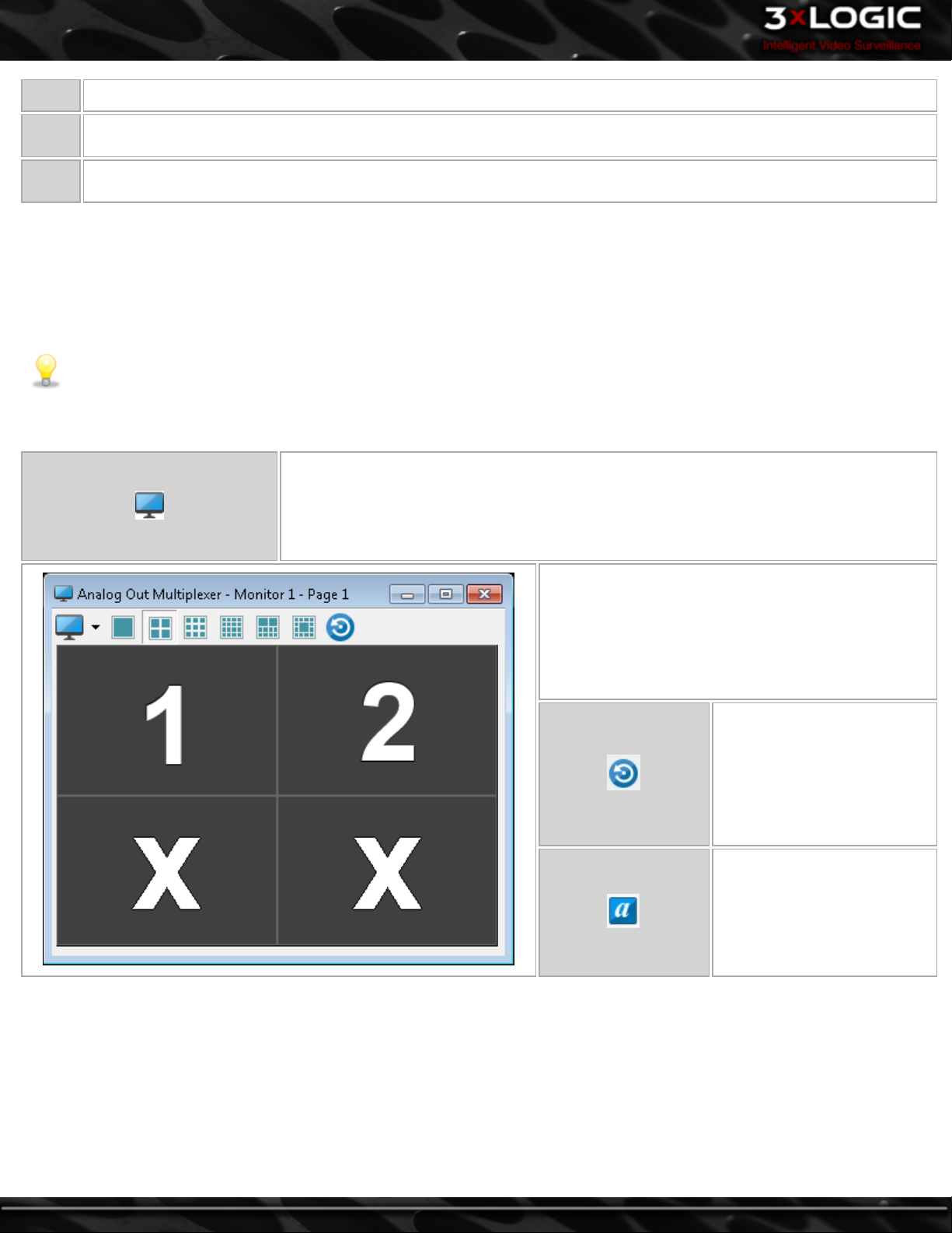
The TV Output Switch changes the camera displayed on the monitor by selecting the camera
number. If no monitors are selected, click on the desired monitor number before selecting
the camera number.
On systems supporting Mux/Analog Out, you can also select the Setup Analog Out Mul-
tiplexer menu item, which opens the Analog Out Multiplexer window (see below).
To arrange cameras within the selected display grid,
right-click on a particular position and select a camera. Camera positions are configured separately for
each grid style.
Undoes any layout changes
that have been made since the
Analog Output Multiplexer
window was last opened.
Toggles captions on and off
for the Analog Output Monitor
video feeds.
-8-
©2014 3xLOGIC Inc. | VIGIL Server - User Guide
Page 18
3.4 Live Viewer Display Controls
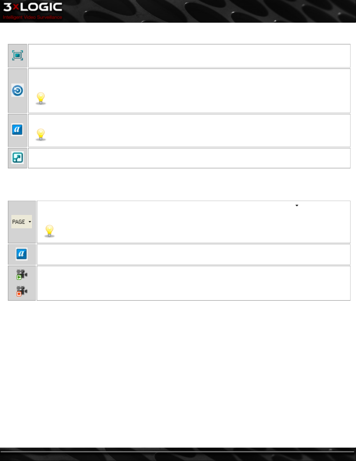
Changes the Live Viewer to full screen mode. To exit full screen mode, click the X in the bottom right corner or press the
escape key on the keyboard.This mode may only be accessed via right click on the live viewer display depending on your
VIGIL Server's capture card.
Click the Restore Original Display Layout button to return to the previously displayed layout or to the layout where the
last camera change was made.
Note: To reload default window sizes and locations, select Tools | Reset Window Positions from the menu, or
select Reset Window Positions from the Tools button drop-down menu. To reset all camera positions to default for
the current layout, right-click on any camera feed within that layout and click Reset To Default.
Toggles captions on the Live Viewervideo feeds on and off.
Note: Captions are not included in the recorded footage.
Toggles the display size of the camera when in Single Live View display mode.
When in Hardware Rendered mode, some of the options differ from Software Rendered mode. For example, the right-click context
menu only has the options of Copy, FullScreen and QuickSearch.
The following buttons are available in the Live Viewer window for Hardware Rendered mode:
Cycles through which camera is displayed in the first position in the live viewer window. Clicking allows you to
select a camera directly.
Note:When in Single Live View display mode, the button PAGE is replaced with CAM, where the function is to
change between cameras rather than pages of cameras.
Toggles captions on/off the Live Viewer video feeds.
Turns on/off all live video feeds. This feature does not affect recording.
Certain capture cards can change between Hardware Rendered and Software Rendered mode. Instead of entering the settings, you
can click the arrow beside the Live button on the main VIGIL Server toolbar to select one of these two modes.
©2014 3xLOGIC Inc. | VIGIL Server - User Guide -9-
Page 19
3.5 Alarms and Relays
Depending on the hardware installed with your VIGIL Server unit, you may have access to alarm inputs or relay outputs. The number
of available alarms and relays is dependent on your hardware.
Alarm inputs can trigger recording of video and/or audio based on an externally tripped circuit. Relay outputs can be triggered by
motion alarms, video loss, POS data, or failure of the VIGIL Server.
Opens the Live Alarms or Relayswindow.
Red: Alarm input is triggered. Click the Alarms button to see the number of the alarm which has
been triggered.
The Live Alarms window indicates configured alarm inputs.
Green: Alarm input is enabled.
Red: Alarm input is triggered.
The Relays window indicates configured relay outputs and allows manual control of relays.
Green: Relay output is enabled.
Red: Relay output has been triggered by VIGIL Server.
You can manually turn on/off some relays by clicking on their respective button.
In the example image, the 6th relay has been set to stay closed while the application is open and
cannot be turned off manually.
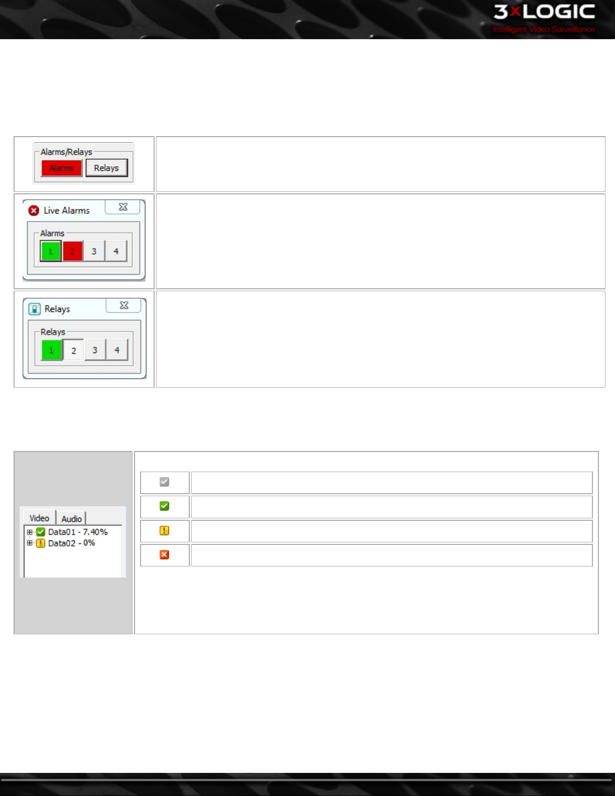
3.6 Media Drive Information
The Media Drive Information section is a live view of the status of the video and audio data storage drives that are configured on the
VIGIL Server.
The status of the data drive is indicated by its icon:
Configured drive
Currently recording on this drive
Drive warning
Drive error, contact your system administrator.
The percentage of free space is listed following the name of a drive.
Further drive information is accessed by clicking the + next to the drive. Here, the path of the drive
and the available/total space of the drive is displayed.
To view drive information for your audio devices, click the Audio tab.
-10-
©2014 3xLOGIC Inc. | VIGIL Server - User Guide
Page 20
3.7 PTZ Camera Controls
Pan/Tilt/Zoom (PTZ) cameras allow navigation to an area of interest and are controlled by the user from the Live Viewer window.
There are three major types of Pan/Tilt/Zoom (PTZ) cameras that exist: digital PTZ cameras, IP PTZ cameras and hard-wired PTZ
cameras.
Digital PTZ camera control allows users to zoom in on a fixed camera and move within the image without controlling the physical
camera itself. Digital PTZ camera control is automatically enabled for all cameras in the live viewer that are not assigned to any
other type of camera control. To disable or re-enable the control, right-click the camera in the live viewer, and then select Digital
PTZ.The live digital PTZ control works in single-view, multi-view and full-screen mode.
IP PTZ cameras must be set up individually in the VIGIL Server settings and control the physical camera through a network connection to the VIGIL Server.
Hard-wired PTZ cameras are also set up individually in the VIGIL Server settings and control the physical camera through a camera
input on the VIGIL Server.
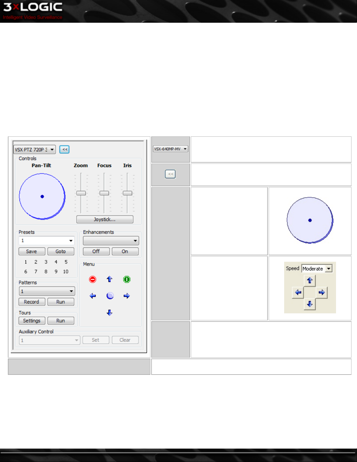
This is a menu of all the PTZ cameras configured on the
VIGIL Server. Select a camera to load for control.
Shows/hides additional PTZ camera controls.
Use the mouse to clickand-drag the blue dot in
the middle of the Pan-Tilt
control in the desired direction. The speed at which
the camera moves
increases as the dot is
dragged closer to the edge
Pan-Tilt
of the circle.
The alternate directional
controls are displayed when
the selected PTZ camera
does not support a full
range of motion (i.e. it cannot pan and tilt at the same
time), or when the PushButton Controls option is
enabled.
Click-and-drag the appropriate slide bar up to increase or
Joystick
Zoom/Focus/
Iris
If a USB Joystick is attached, this button will be available. Once clicked, it
opens the Joystick Customizationwindow.
down to decrease. The speed at which the camera is
adjusted increases as the bar is moved farther from the
center of the control.
©2014 3xLOGIC Inc. | VIGIL Server - User Guide -11-
Page 21
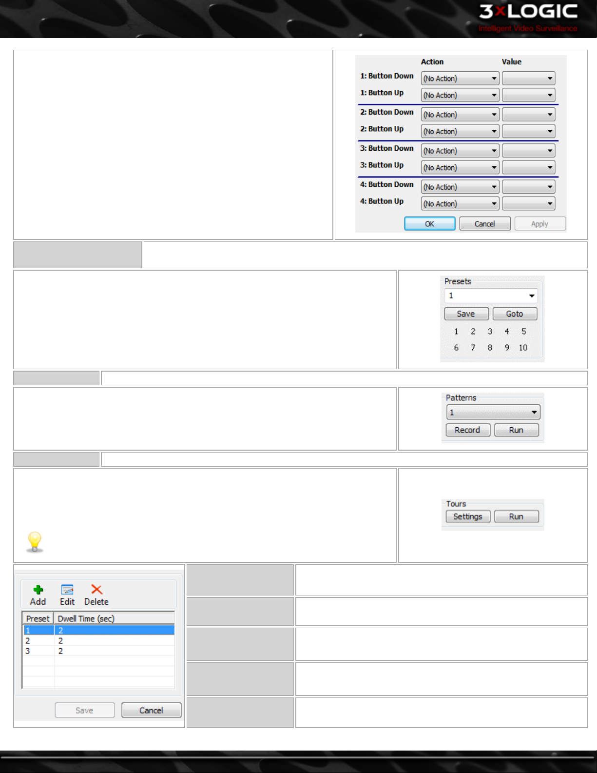
This window allows for customization of each of the joystick buttons.
Use the drop-down menus to assign actions to each button.
To determine which button is which, go into the Windows Control Panel
and select Game Controllers, where the device will be listed. Select it
and click Properties. Click any button on the joystick and the button
number will be highlighted in the resulting window.
Presets
Presets are fixed locations that the camera can save and go to. The presets are stored within the
camera for hard-wired PTZ cameras.
To save a preset, move the camera to the desired preset location, select the preset
number from the drop-down menu and click Save. This will overwrite any presets previously saved to that number.
To move the camera to an existing preset, select a preset from the drop-down menu
and click Goto, or click the button with the preset number on it.
Patterns Control the saved pattern of movement for the selected camera. Patterns are stored within the camera.
Select a pattern from the drop-down menu and click Record. Use the other control buttons to move the camera in the desired pattern. Once finished, click Stop. This will
overwrite the existing saved pattern. Select a pattern from the drop-down menu and
click Run to begin the saved pattern.
Tours A tour is a cycle of camera presets. Tour settings are stored within VIGIL Server.
Click Settings to open the Tour Settings window, where presets are added and set to
run for a specified number of seconds before going to the next preset.
Click Run to activate the tour.The camera will cycle through the presets in the Live
Viewer window.The tour can be ended by moving the camera or pressing Stop.
-12-
Note: Presets must be configured before a tour can be run.
Add Adds a preset to the tour.
Edit Edits a preset in the tour.
Delete Deletes a preset from the tour.
Save Saves changes made to presets.
Cancel
Exits the Tour Settings window without saving any
changes.
©2014 3xLOGIC Inc. | VIGIL Server - User Guide
Page 22
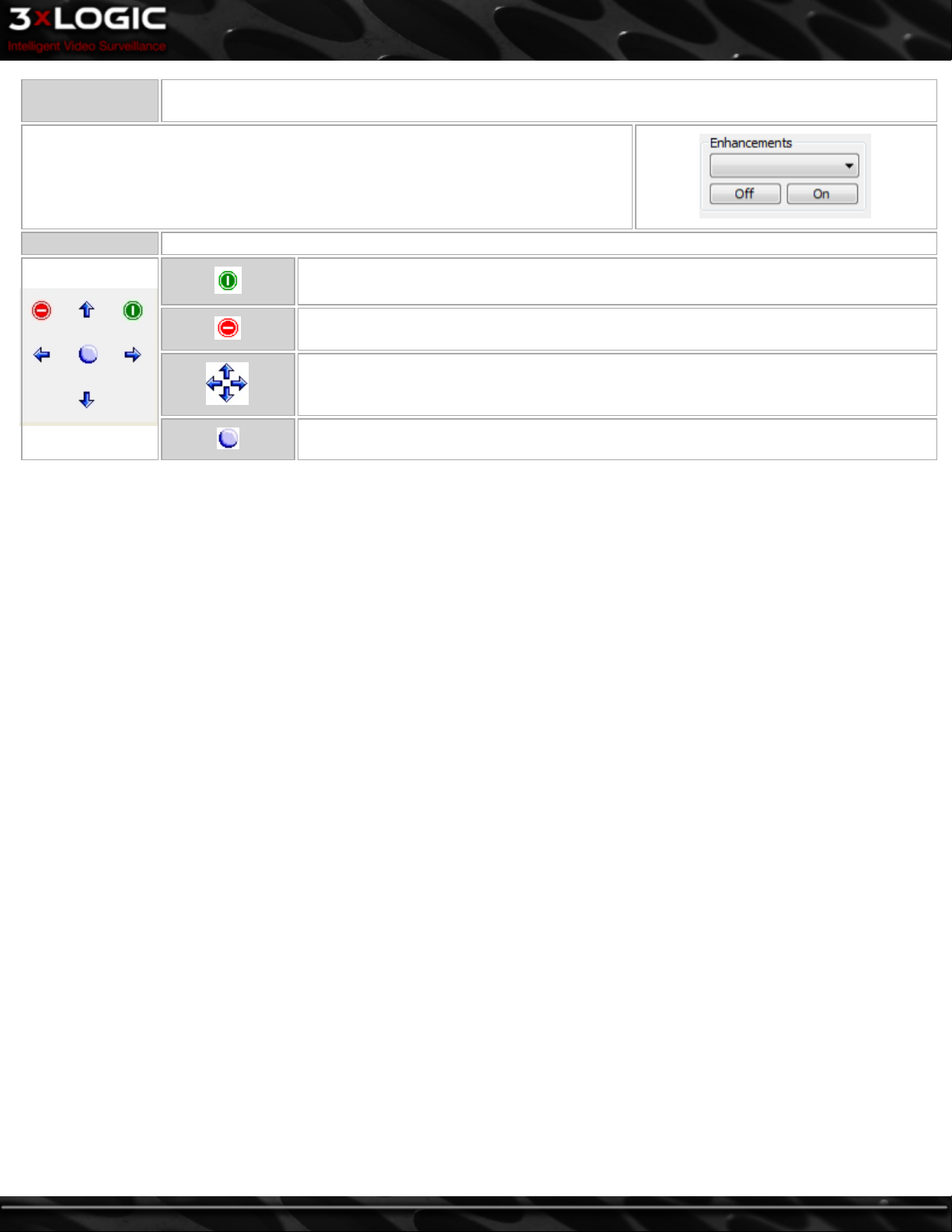
Enhancements
Settings on the camera that can be toggled on/off. These include Color, Sensitivity, Backlight, White Balance
and Auto Focus.
Enhancements can be selected via the Drop Down Box and turned on or off via the buttons.
Menu Some cameras have built-in menus that can be accessed and configured via this tool.
Displays the camera’s menu; it may take a moment to appear.
Exits the camera’s menu. You can also navigate to the Exitmenu option and click the Select
button.
Camera menu navigation buttons.
Camera menu select button.
©2014 3xLOGIC Inc. | VIGIL Server - User Guide -13-
Page 23
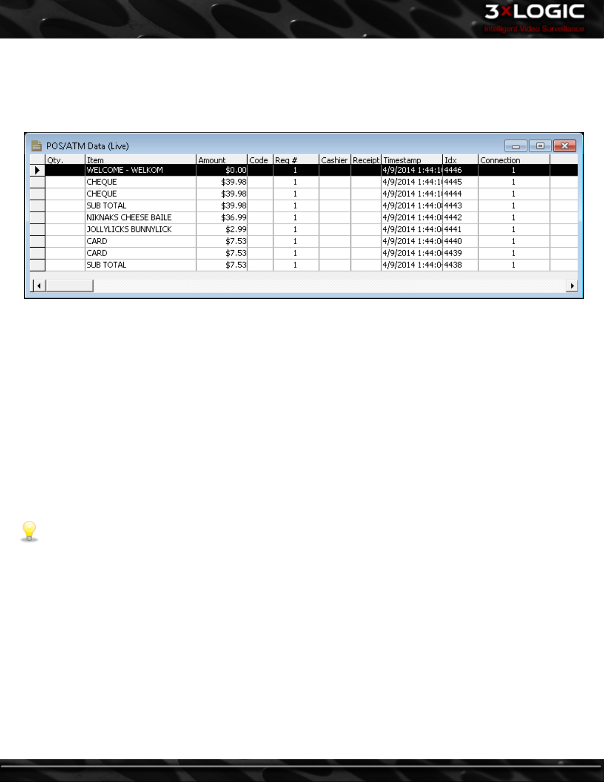
3.8 Live POS / ATM Data
Live POS/ATM Data refers data generated by a compatible data system such as a Point of Sale system, ATM or Access Control, and
received by VIGIL Server in real-time. To open the Live POS/ATM Data window, select Live POS/ATM Data from the Tools button
drop-down menu in the main VIGIL Server window. The POS/ATM Data (Live) window displays live data from all configured Data
Sources.
The POS/ATM Data (Live) window presents POS data in tabular form organized via the following columns:
l Qty – The quantity of the item purchased.
l Item – The item purchased.
l Amount – The price of the item purchased.
l Code – The transaction code identifies the type of transaction.
l Reg # – The cash register number.
l Cashier – The cashier currently logged into the POS system.
l Receipt # – The receipt number of the current receipt.
l Timestamp – The time at which the Point of Sale event occurred.
l Idx – A unique identifier to quickly identify and find Data line items.
l Connection - Identifies the POS Connection from which the data is being received.
The column headers are all able to be resized as well as rearranged within the window. To move a column, click on the column
header that you would like to move and then click another column header to swap column positions. To reset the column locations,
right-click in the POS/ATM Data (Live) window and select Reset Column Order. Double click a column header to automatically
resize the column to the content width.
Note: Some types of data sources do not support all of the columns that are available. The columns are designed for POS
Data, other Data sources are designed to insert Data to the closest matching column.
-14-
©2014 3xLOGIC Inc. | VIGIL Server - User Guide
Page 24
4 Searching
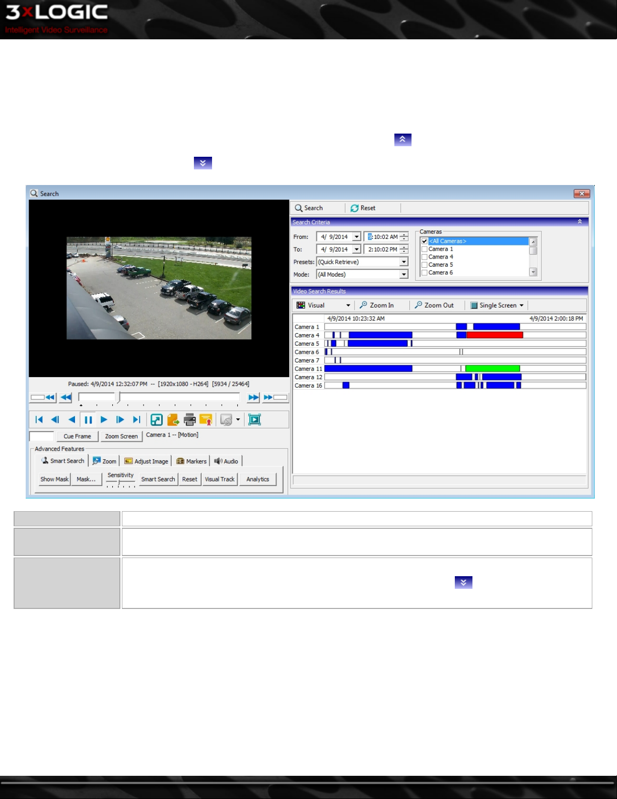
VIGIL Server offers a robust set of tools for searching and playing video footage and data. To open the Search window, either click
Search on the main VIGIL Server icon toolbar, or select Search | Search Footage and Data from the main menu.
The Search window is divided into two major portions: the playback section on the left and the searching section on the right.
Each of the Search window sections can be minimized by clicking the double arrows in the title bar. When a section is already
minimized, it can be restored using the double arrows.
Search Performs a search based on the current criteria.
Reset
POS/ATM Data
Resets all search criteria and data filters to their default values. The From/To time defaults to the
past hour from when Reset is clicked.
If a POS data connection has been configured, this button will open the POS Data Filter and Data
Search Results sections. Click the POS/ATM Data Filter section title bar to specify the data
search criteria.
©2014 3xLOGIC Inc. | VIGIL Server - User Guide -15-
Page 25
4.1 Searching Video
When first opened, the Search window
defaults to a search of all cameras,
recording in all modes, from the last
hour. Click the Search button to
retrieve all footage meeting the specified criteria.
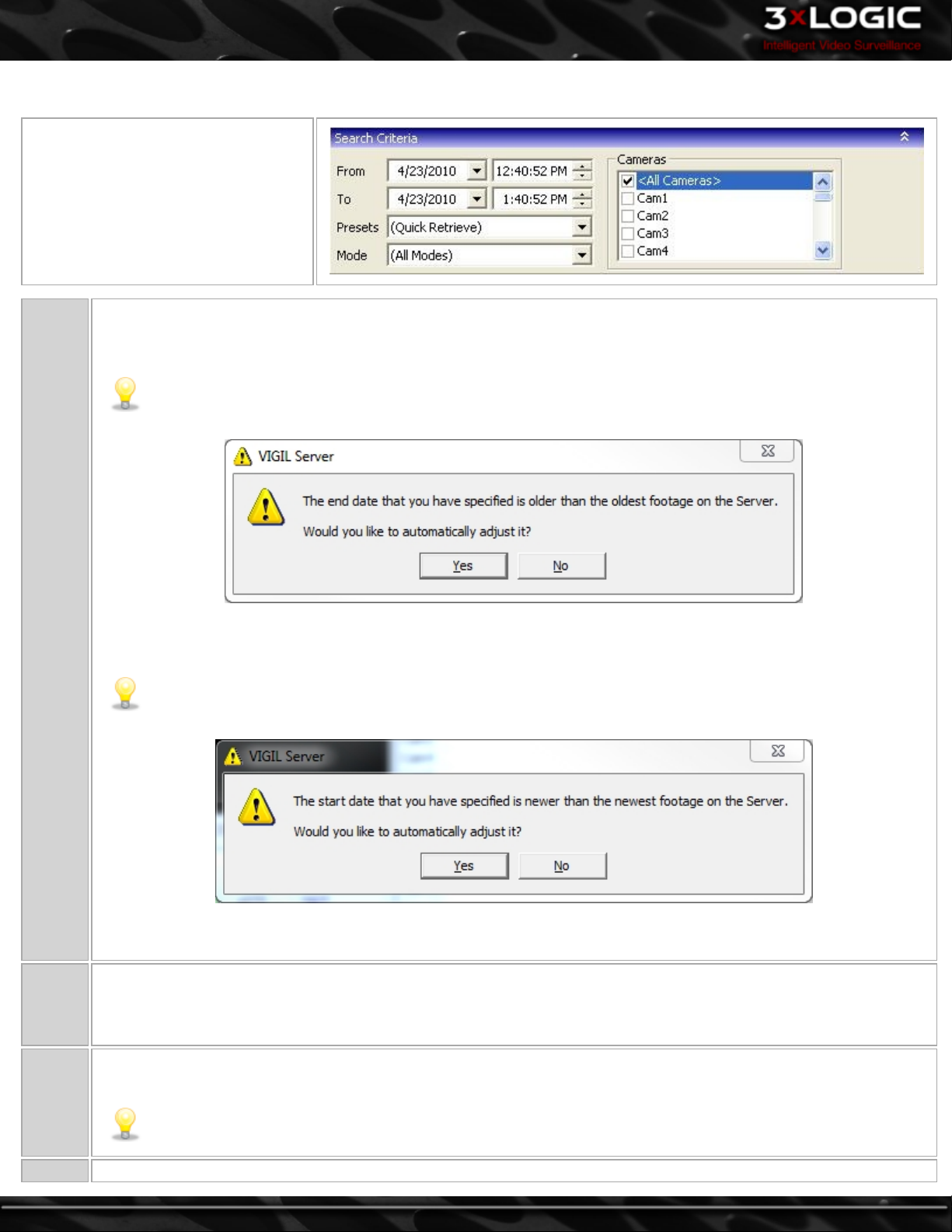
You can specify the start date/time and end date/time of your search. By default, VIGIL Server allows you to search
across multiple days. This can be changed to default to One Day in the Settings window, in the VIGIL Server Settings |
Search Tab.
Note: If the searched footage To date or time is older than the oldest footage on the VIGIL Server, the following
prompt will appear:
From/To
Presets
Mode
To automatically adjust the To date to be an hour later than the oldest footage on the VIGIL Server click Yes. If you do
not want to have the date range adjusted, click No.
Note: If the searched footage From date or time is newer than the newest footage on the VIGIL Server, the fol-
lowing prompt will appear:
To automatically adjust the From date to be an hour earlier than the newest footage on the VIGIL Server click Yes. If
you do not want to have the date range adjusted, click No.
This drop-down menu includes preset search intervals in hourly increments from 1 hour up to 8 hours. Additionally, selections for 15 and 30 minutes can be added by checking Quick Retrieve Short Intervals in the Settings | VIGIL Server Set-
tings | Search Tab. When a selection is made, the From/To times are adjusted accordingly. Selecting Custom Search
opens the Custom Search window where searches that are performed frequently can be created or run.
Making a selection from this drop-down menu will restrict the returned footage to only the selected type: All Modes, Con-
stant, Motion, All Alarms, Digital Input Alarms, Motion Alarms, POS/ATM Alarms or Video Analytics Alarms.
Note: When selecting Video Analytics Alarm mode, please note that retrieved footage will surround Alarm
events associated with VA rules, not all instances of video analytics being utilized.
Cameras This allows you to restrict your search to a limited set of cameras. By default, all cameras will be searched.
-16-
©2014 3xLOGIC Inc. | VIGIL Server - User Guide
Page 26
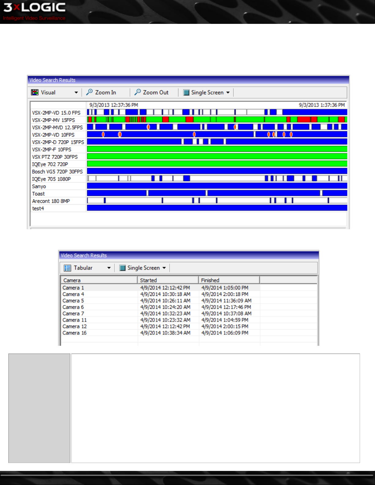
4.1.1 Video Search Results
After completing a search, the results are displayed in the Video Search Results pane as seen below. This pane is expandable and col-
lapsible if the POS/ATM Data search is enabled.
Visual Display
Tabular Display
Visual / Tabular
Click this button or use the drop-down menu to switch between Visual and Tabular display options.
Visual display is a graphical representation of the search results. The visual footage chart shows the
period of time searched with footage recorded displayed as blocks of color representing the recording
mode: Green for Constant, Blue for Motion or Red for Alarm.
When the mouse is moved within the chart, a line is drawn indicating the point in time under the cursor,
which is displayed below the Video Search Results. Clicking within the chart will begin playback of the
selected camera at that time, clicking in a white section of the chart will begin playback of the next
available footage.
Tabular display is a table with the start and end dates and times of the available video footage. Clicking on a table row will begin playback of the selected camera. The tabular display cannot show gaps in
video footage.
©2014 3xLOGIC Inc. | VIGIL Server - User Guide -17-
Page 27
Zoom In Allows you to zoom in on the Visual DisplayVideo Search Results for greater precision.
Zoom Out Allows you to zoom out on the Visual display Video Search Results for a wider view.
The playback options allow you to control how your results will be played back. Selecting Single Screen
Single / Multi Screen
will display one camera at a time during playback. Selecting Multi-Screen will play back up to four cam-
eras simultaneously in a 2 x 2 multi-screen layout. In either mode, cameras are added to the Playback
window by selecting them in the results panel.
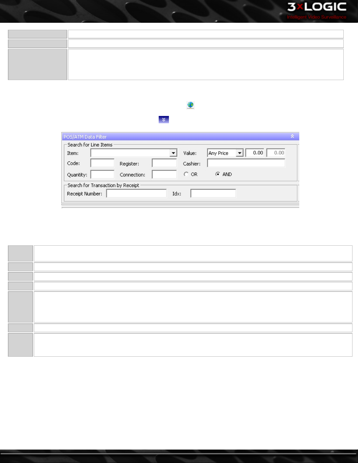
4.2 Searching POS/ATM Data
Configure a POS/ATM data connection in the Data tab and click the button to open the POS/ATM Data Filter and Data Search
Results sections. Click the POS/ATM Data Filter title bar to open the POS/ATM filter criteria section.
4.2.1 Search for Line Items
Use the Search for Line Items section to find specific data within the date and time indicated in the Search Criteria section. When
searching for line items, normal search criteria are also included (i.e. From and To date/times, selected cameras).
Item
Code Type in text to search by Code.
Register Type in a number to search by Register Number.
Quantity Type in a number to search by Quantity.
Value
Cashier Type in text to search by cashier number or name.
Or/And
Type in text to search by Item. Use the drop-down menu to select a recently searched item, remembers last 10 searched
for items.
Matches results in the Amount column. By default, Any Price is selected. If you want to match a certain value, select an
operator and input a value. The >= means “more than or equal to” the value that you input. For example, if the operator
>= is used with the value of $20.15, any POS data with the value of 20.15 and higher will be returned. The <= operator
means “less than or equal to”, while the = operator simply means an exact value.
Logical operators that will assist in searching with multiple criteria. By default, this is the OR operator, which will
match results in any of the used POS data criteria fields. Alternatively, the AND operator will match results in all of the
used POS data criteria fields.
-18-
©2014 3xLOGIC Inc. | VIGIL Server - User Guide
Page 28
4.2.2 Search for Transaction
This type of search looks for a unique line item or receipt number and disregards the other criteria.
Receipt
Number
IDX
Type in text that will match results in Receipt # column. The search results will include 10 seconds before the start of
the receipt and 10 seconds after the end of the receipt.
Type in text that will match results in IDX column. If the IDX contains a receipt number, the Data returned will be that
receipt number and all IDX values corresponding to it within one hour. If there is no receipt number for the searched IDX
value, the returned results will be based on the timestamp of that IDX. The search results will be +/- 10 seconds from the
timestamp of the IDX.
Note:Depending on the recording configuration of your cameras, there may be no footage matching your search criteria.
The following options are available when a POS/ATM data record within the Data Search Results pane is right-clicked:
Copy Line Copies the selected line of POS/ATM data to the Windows clipboard.
Export
Print
Mark
Video
Region
Search for
Receipt #
Reset Col-
umn
Order
Saves the selected POS/ATM data to a preset destination. Select the destination folder and enter a file name, then
click Save. Export destinations are set in the Settings under Media Drives.
Prints the selected POS/ATM data to the default printer. You can also select the printer button and select Print Data
from the context menu.
Adds markers to the playback slide bar to easily identify relevant portions of video. Options are +/- 10, 20, or 30 seconds. You must have the Playback window open with video footage selected for this option to become available.
Narrows the Data Search Results to display only items with the selected Receipt Number.
Resets the order of the Data Search Results columns to their default positions.
Note: When a POS/ATM line item is selected in the Data Search Results and there is no video footage that matches that selec-
tion, the next available video frame will be displayed along with the POS/ATM line item that is associated with it.
©2014 3xLOGIC Inc. | VIGIL Server - User Guide -19-
Page 29
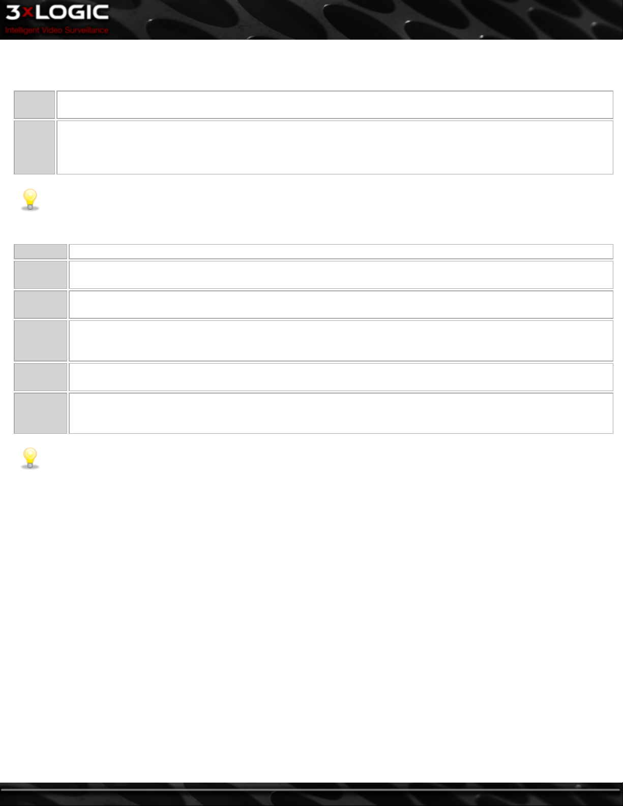
4.3 Custom Search
A Custom Search that includes specified
search criteria can be created and saved.
The Custom Search window can be
accessed from the Presets | Custom Search
drop-down menu. It can also be opened
from the toolbar menu (Search | Custom
Search). When selected, the Custom Search
window will appear.
Add
Edit
Delete Deletes an existing Custom Search. Select an entry and click Delete.
Run Runs an existing Custom Search. Select an entry and click Run.
Descrip-
Cameras
Opens the Add Custom Search window. Once a Custom Search has been added, click Apply to save the search. See below
for more info.
Opens the Edit Custom Search window for the selected search. Select an entry and click Edit. Once a Custom Search has
been edited, click Apply to save the changes.
The name of the search that will appear
tion
Server
Time
Filter
in the Custom Search list.
Select the server the custom search will
be run on from the drop down list.
The start time and end time to be
searched.
Select the camera(s) to search, or select
All Cameras.
Include Data – When enabled, the Custom
Search will include the POS/ATM data
criteria specified.
-20-
OR/AND - Logical operators that will
assist in searching with multiple criteria.
Data
By default, this is the OR operator,
which will match results in any of the
POS/ATM data criteria fields. The AND
operator will only match results that
have matched results in all of the
POS/ATM data criteria fields.
Note: You must save Custom Searches before they can be run. To do this press the OK or Apply buttons.
©2014 3xLOGIC Inc. | VIGIL Server - User Guide
Page 30
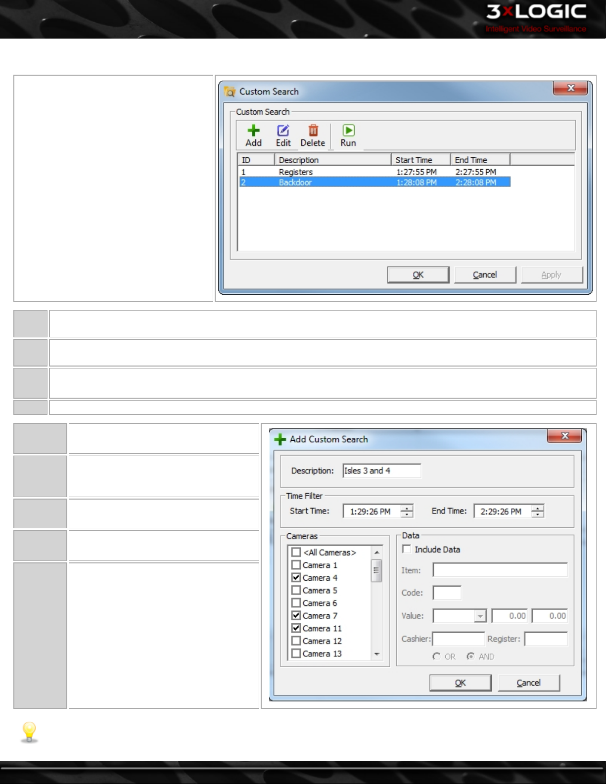
4.4 Video Playback
To play recorded video footage, click a camera in the Video Search Results pane in the Search window. The camera will load for
playback and the retrieved footage will begin playing.
Note: Network cameras may record and play back at a slower rate than what was set in the Recording Speed window,
depending on the available bandwidth.
Information about the camera feed is displayed below the Playback window. This information includes the playback status, the date
and time of the footage, the frame rate if currently playing, the resolution and recording CODEC of the footage, the current frame
number, and the total number of frames.
©2014 3xLOGIC Inc. | VIGIL Server - User Guide -21-
Page 31

4.4.1 Controlling Playback Video with Digital PTZ:
Cameras can be controlled during playback using the digital PTZ camera control in the same way as the Live Viewer. Because digital
PTZ controls movement within the image, it can be used for both live and playback video. The digital PTZ controls will work for
every camera that is loaded for playback regardless of the camera control type specified in the settings. The digital PTZ control
works in single-screen, multi-screen, zoom-screen, and full-screen mode.
4.4.2 Camera Right-click Menu:
Remove Removes a camera from playback.
Copy
For cameras using the 360 Dewarping PTZ Camera Control type, the video can be manipulated in the playback window using the
following right-click menu options:
Source Video Only
(Rotate Disabled)
Source Video Only
(Rotate enabled)
360 View and Source
Video
Copies a still shot of the current image to the Windows clipboard. If the image is zoomed in, a Copy
Zoomed option will be available as well.
This option is enabled by default. This feature allows users to zoom in and move cameras during playback.
Click on an area of interest and then use the mouse scroll to zoom in.Click-and-drag to move the image
after it is zoomed in.
This feature allows users to zoom in and rotate cameras during playback. Click on an area of interest and
then use the mouse scroll to zoom in. Or, click-and-drag to rotate the image.
This feature splits the playback image into 4 quadrants. The first quadrant shows the full image, and the
second, third and fourth quadrants show different zoomed sections of the image. To load an area of interest in one of the zoom quadrants, click on a zoom quadrant and then click on the first quadrant to load
that section. The zoomed sections can be clicked on directly and then rotated.
4.4.3 Playback Buttons:
Click-and-drag the Variable Speed Playback Slider to change the speed of the video
playback. The variable speed playback tool tip displays the number of times faster the
variable speed playback is than the Recorded Speed. You can also right click on the
button to select the speed directly.
Click the Fast Backward or Fast Forward button to playback at Maximum speed without skipping any frames.
Skips to the very beginning/end of the video footage.
Skips one 10th of the footage if clicked while playing the video footage.
While paused or stopped, click to playback frame by frame. The mouse scroll wheel
can also be used to do this by selecting the playback slide-bar.
Pauses the video footage.
Plays the video footage backward or forward.
Click-and-drag the slide-bar to move to a
different point in the video clip.
-22-
Stretches the playback image to fill the Playback window.
Note:Footage recorded in 704x480 resolution or higher is scaled down to fit within the Playback win-
dow.
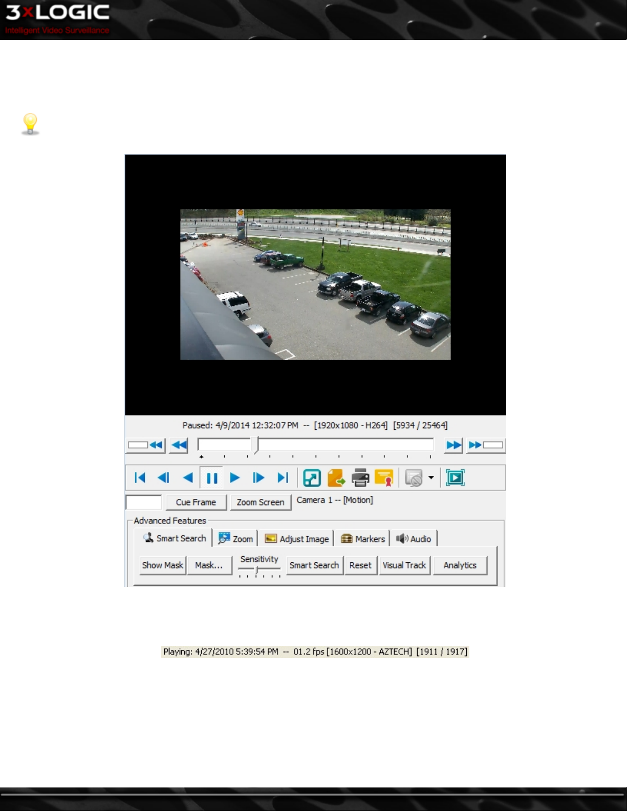
For exporting Still Image, Video Footage, Audio or POS/ATM Data.
©2014 3xLOGIC Inc. | VIGIL Server - User Guide
Page 32
Click and select Print Still Image to print the current frame, or select Print Data to print the POS data currently displayed in the Data Search Results pane. Defaults to Print Still Image if no Data Search Results avail-
able.
Click to Authenticate the currently selected video footage. For more information on authentication.
Click to toggle the Data On-Screen Display feature, where POS/ATM data is displayed with the video footage.
Click to play in Full Screen mode. Double-click on the image to return to the standard Playback window.
Note:To zoom in on an image in Full Screen mode, hold down the Control key and left-click. To
zoom out on an image, hold down the Control key and right-click.
Cue Frame
Zoom / Normal
Screen
Cues the playback video to a specific frame. Enter a frame number in the text box and click the Cue Frame
button.
Enlarges the Playback window so details in the playback image are easier to see. When in Zoom Screen mode,
click the Normal Screen button to return to the original window.
Displays the Camera name currently playing and the type of recording.
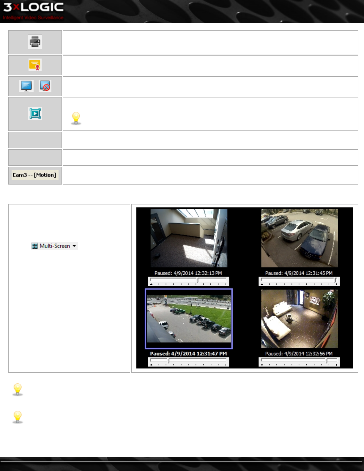
4.5 Multi-Screen Playback
Select from the Video
Search Results toolbar to playback up to
four cameras simultaneously. The Playback
window will be divided into quadrants; they
are filled in clockwise order beginning from
the top left. To add a camera to the playback, click on its name or some point
within its timeline. If all quadrants have
cameras loaded, clicking a new camera will
replace one of the initial cameras. Footage
will play back from all loaded cameras
simultaneously.
Note:If a camera does not have footage for a time when other cameras do have footage, the video will pause with an over-
lay stating “No frames were found” while other cameras continue to play. When the playback time reaches a point where
the paused camera has more footage, its playback will resume. When there is no footage for any camera, the playback skips
to the next time where footage exists for at least one camera.
Note:To revert to Single Screen playback, first select a camera and then click the Multi-Screen button in the Video Search
Results section.
©2014 3xLOGIC Inc. | VIGIL Server - User Guide -23-
Page 33
4.6 Advanced Features
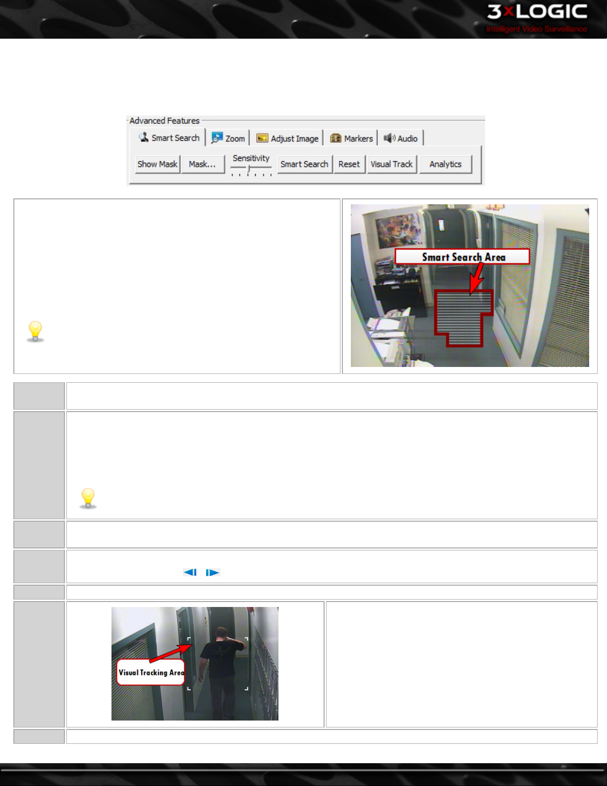
4.6.1 Smart Search
The Smart Search feature refines the loaded video footage based on motion detected within a user-defined region.
To perform a Smart Search, you must first define or “mask” a motion
detection region. To do this, click Show Mask and draw on the playback
image. Any time a clear area is clicked on, the mask is expanded. Alternatively, when a masked area is clicked on, the mask is removed. Click
the Smart Search button to perform the search. Once the search is com-
plete, only video frames that contain motion in the masked region will
be loaded for playback.
Note:If there is more than one masked region (i.e. two or more
disconnected masks), the Smart Search will load video frames
that contain motion in any of the regions.
Show
Mask
Mask
Shows/hides the Smart Search mask. A mask can only be edited when the Show Mask button is latched on.
Offers some quick options for modifying masks:
Clear – Erases all masks on the image.
Select All – Masks the entire image.
Invert - Swaps clear and masked areas.
Note:The Show Mask button must be latched on for these options to be available.
Sensitivity
Smart
Search
Reset Removes all Smart Search masks and restores the originally loaded footage.
Visual
Track
This slider controls the sensitivity of the motion detection algorithm used by the Smart Search function. To the left is
less sensitive, requiring larger change in motion; to the right is a more sensitive, detecting smaller movement.
Performs the Smart Search. Video frames that do not contain motion in the masked regions are removed from the
loaded footage. Use the buttons to skip back/forward to the next Smart Search frame.
When enabled, the Visual Tracking feature tracks moving
objects by the placement of white corners around the
object.
Analytics Displays a menu where Video Analytics information can be overlaid on the playback footage.
-24-
©2014 3xLOGIC Inc. | VIGIL Server - User Guide
Page 34
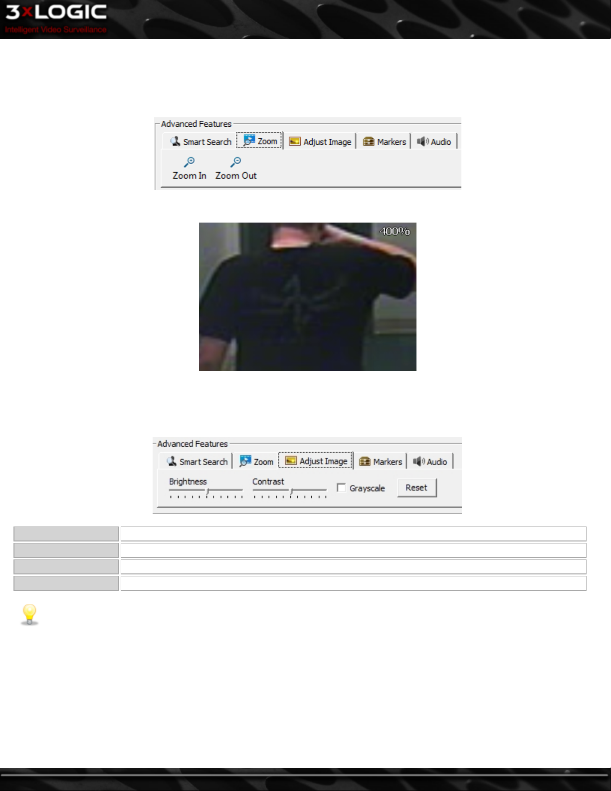
4.6.2 Zoom
Playback footage can be zoomed by selecting the Zoom tab from the Advanced Features section. When the cursor is moved over the
Playback window, a zoom outline will be displayed to indicate the region that will be magnified. Left-clicking zooms in and rightclicking zooms out of the image. Zoom In and Zoom Out buttons are also available in the Zoom tab.
The magnification factor is displayed in the upper right-hand corner of the Playback window.
4.6.3 Adjust Image
When playback is paused, you can adjust the image by selecting the Adjust Image tab from the Advanced Features section. The
adjusted image can be exported or printed.
Brightness Adjusts the brightness of the current frame.
Contrast Adjusts the contrast of the current frame.
Grayscale Toggles between a grayscale and color image. Only still images will export in grayscale.
Reset Returns the image to its default values.
Note: Only a paused image can be adjusted; adjustment of footage during playback is too CPU intensive. Any adjustment
you have made will be reapplied when footage is paused again.
©2014 3xLOGIC Inc. | VIGIL Server - User Guide -25-
Page 35
4.6.4 Markers
During playback, if only a sub-range of the loaded footage is of interest it can quickly be selected by using Markers. To use Markers,
select the Markers tab from the Advanced Features section.
Position the footage navigation slider at the beginning of the sub-range and click the
Start / End Range
Start Range button. You will notice a small marker appear below the starting point(circled in red, right.) Next, navigate to the end of the sub-range and click the End Range
button.
Clear
View
Removes the sub-range markers. If the sub-range is cleared when the View button is latched on, the playback will return from the sub-range to the fully loaded footage.
Loads the sub-range for playback. The playback information will indicate that a sub-range is currently displayed. All of the playback controls will operate on only the sub-range of footage.
Note:If multiple cameras are loaded for playback in Multi-Screen mode, each camera can have its own unique sub-range of
footage.
Note: If a sub-range has been defined, only the sub-range will be saved when video is exported.
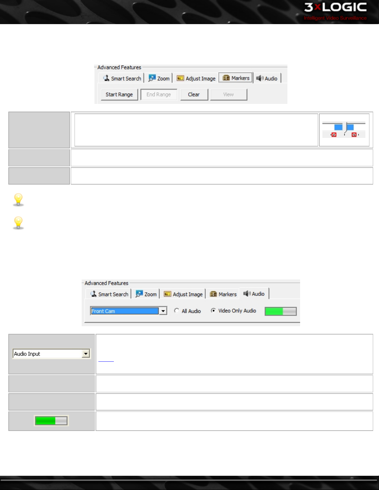
4.6.5 Audio Playback
If audio recording is enabled and configured in the VIGIL Server settings, the Audio tab will become available in the Advanced Features section of the Search window. Selecting an audio channel from this tab allows you to playback recorded audio along with video
footage.
-26-
All Audio
Video Only Audio
To choose which audio channel to playback, select the channel from the drop-down menu in the
Audio tab.
When selected, all audio from the specified channel is played back even when there is no corresponding video footage for the playback time.
When selected, audio from the specified channel is played back only when there is corresponding
video footage for the playback time.
This Audio Level Meter indicates the signal strength of the currently playing audio.
©2014 3xLOGIC Inc. | VIGIL Server - User Guide
Page 36
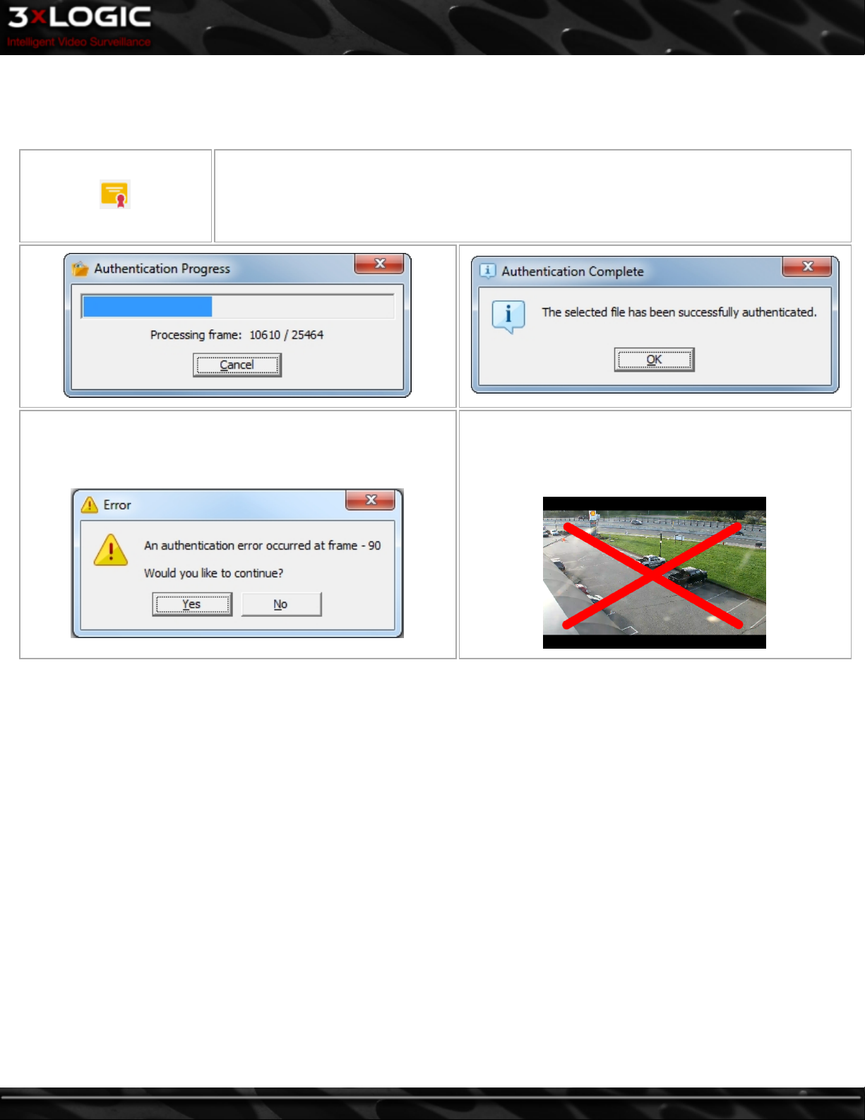
4.7 Authenticating Recorded Video
VIGIL Server embeds a security key in recorded footage for each video frame. These keys can be easily checked to verify that the
footage is authentic and has not been tampered with.
Begins the authentication process; a window opens displaying the progress. Depending on the length
and location of the video footage, authentication may take several minutes to complete. You can
cancel the authentication at any time by clicking Cancel. Any frames that were processed prior to
cancelling have been authenticated. If the video is authentic, the Authentication Complete mes-
sage will be displayed.
If the video has been tampered with, the authentication will halt at
the first damaged frame and provide an error message with the
problem frame number.
If Real-Time Authentication (in VIGIL Server Settings |
Search tab) is enabled, during playback a large red X is displayed over the frame if the footage does not pass authentication.
©2014 3xLOGIC Inc. | VIGIL Server - User Guide -27-
Page 37
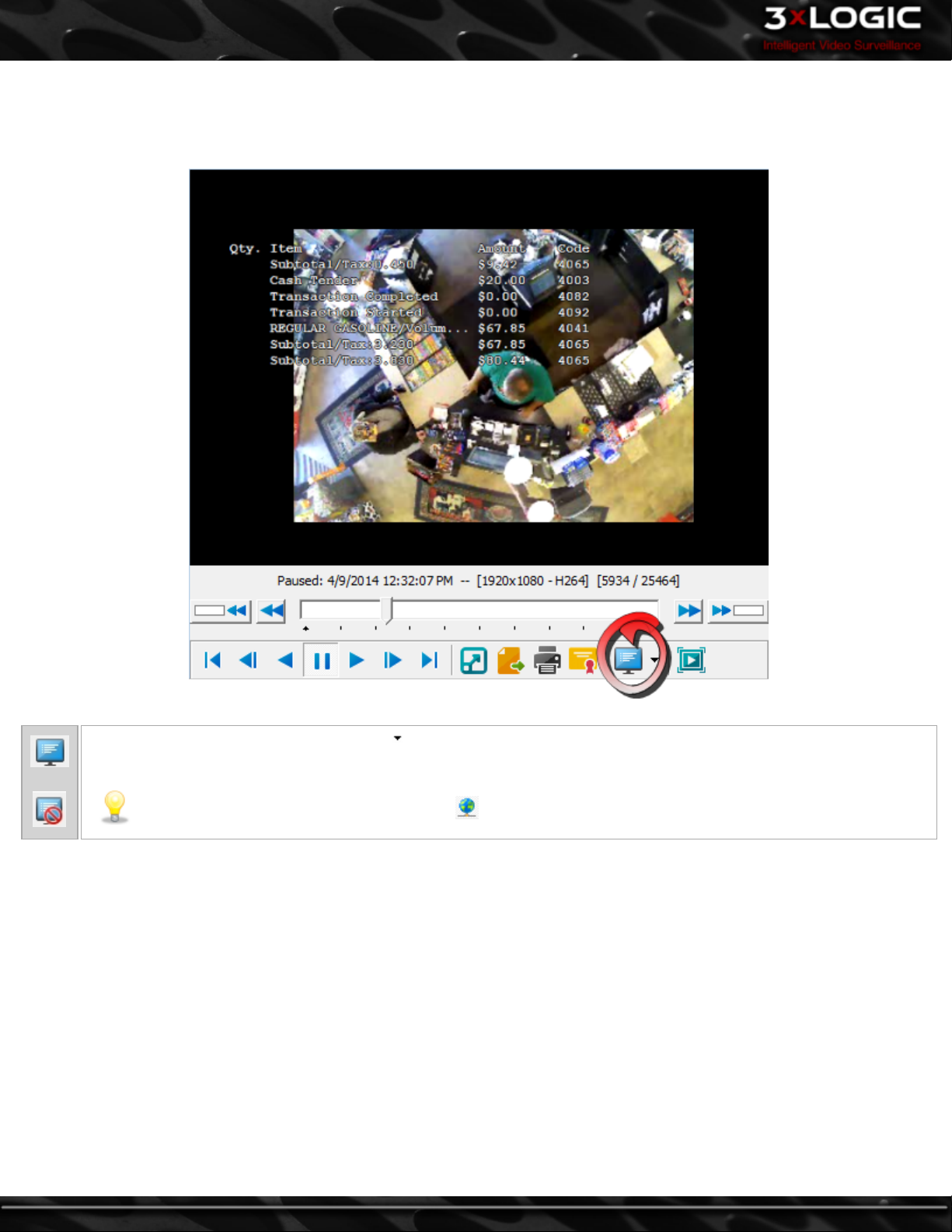
4.8 On-Screen Display - POS/ATM Data
When POS/ATM search results are found and a camera is loaded for playback, the On-Screen Display (OSD) feature can be enabled.
Enabling this feature will overlay POS/ATM records on the video while it is played back.
Enables/Disables the OSD of POS data. The opens the OSD context menu, allowing you to Enable/Disable the OSD or
open the Configure OSD window.
Note:The OSD feature is available when the POS/ATM Data button in the Search window is latched on.
-28-
©2014 3xLOGIC Inc. | VIGIL Server - User Guide
Page 38

5 Exporting
Video footage can be saved either as a single frame still shot or as a video file, audio and POS/ATM data can be saved either embedded within video footage or in a separate document. This process is referred to as “exporting”.
Note: To export you must have at least one export destination configured.
Note: If Export Auditing is enabled, required information must be entered before selecting the destination folder for both
images and video exports.
5.1 Exporting, Printing, or Emailing Images
Single frame shots can be saved or emailed in either Bitmap or JPEG format. BMP images retain all of the original image detail, but
are typically much larger than JPEG images as a result. JPEG images are compressed and are typically indistinguishable from the original image when the JPG quality is 70 or greater.
Opens the Export context menu where the file format is selected. The Export button is only enabled
when video footage is selected in the Playback window.
Select Bitmap to save the current frame in bitmap .BMP format. Select the export destinations and
enter a filename. Click Save when finished or Cancel to exit without saving.
Select JPEG to save the current frame in JPEG .JPG format. Select the export destination and enter a
Still Image
E-mail
filename. Additionally, you may select a quality setting for the JPG image by adjusting the slider.
Closer to the left side means a lower quality, smaller sized file; further to the right means a higher quality, larger sized file. For the most part, the default compression setting is the best choice. Click Save
when finished or Cancel to exit without saving.
Select Bitmap or JPEG to e-mail the current frame in .BMP or .JPG format. Enter the email subject,
body and recipients.
Note:For email to function properly, a valid SMTP Server must be configured in the VIGIL
Server Settings tab.
Select the destination you want to save the image to. You can select
multiple destinations by checking the corresponding boxes, as well as
create subdirectories by using the New Folder button. When exporting
a Bitmap the Quality slider will not be visible.
Prints to the Windows default printer. Click this button and select Print Still Image.
Note:The image will be sent to the default Windows printer only. If one has not been con-
figured an error message will appear.
©2014 3xLOGIC Inc. | VIGIL Server - User Guide -29-
Page 39
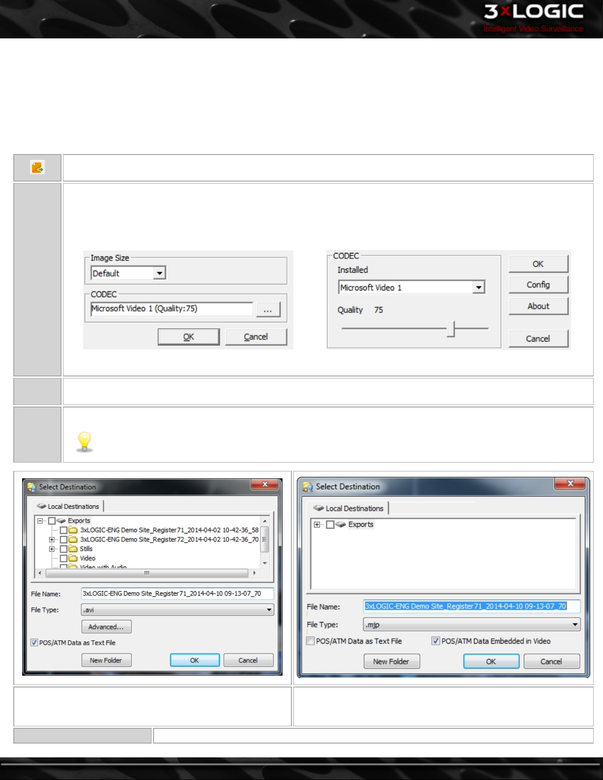
5.2 Exporting Video
Video footage can be exported in Microsoft AVI video format or in Authentic Video format which uses 3xLOGIC’s proprietary Motion
JPEG AZTECH™ format. Video clips exported in Authentic Video format can be played using the 3xLOGIC DV Player program. AVI for-
mat video clips can be played using Windows Media Player or any other player that supports standard AVI format.The Authentic
Video format is recommended when exporting video clips as evidence since the authenticity of the clip can be verified using DV
Player. VIGIL Server allows video exports to include the VIGIL DV player program to ensure that playback software is available for
Authentic Video exports.
Opens the Export context menu. Select the type of file you want to export.
Saves the current video footage in AVI format. Select the export destinations and enter a filename.
Clicking the Advanced button will open the CODEC Settings window that allows you to set the image size the video will
be saved at. The … button will open another window where you can select and configure the CODEC used during the
encoding process.
AVI
Authentic
Video
Data
Click OK when finished or Cancel to exit without saving.
Saves the current video footage in MJPEG format. Select the export destinations and enter a filename. Click Save when
finished, or Cancel to exit without saving.
Export the POS/ATM data in a text file.
Note:To export POS data you must have the POS Connection Settings configured in the Settings | Data tab.
POS/ATM Data as Text File – POS/ATM data is included with
the export in a separate text file.
Audio Data Embedded in
-30-
Exports any audio on the selected channel with the video file.
POS/ATM Data Embedded in Video - The POS/ATM data will be
overlaid on the video image when the exported video file is
opened using DV Player.
©2014 3xLOGIC Inc. | VIGIL Server - User Guide
Page 40
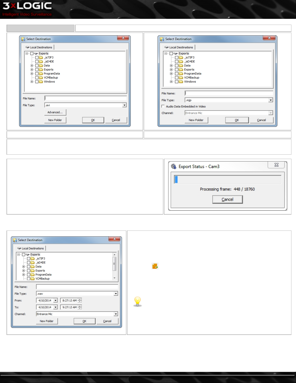
Video
AVI export with no audio configured Authentic Video export with audio available
Select the destination to which you want to save the footage. You can select multiple destinations, as well as create subdirectories using the New Folder button.
When choosing to export video (from a playback frames left -edge control menu,) you will have the option of exporting the selected camera
footage or all cameras footage. Choosing Selected Camera will export
only the currently selected camera footage. Choosing All Cameras will
export footage from all currently displayed cameras to separate files.
The files will have the camera name appended to the filename. Export
progress will be displayed as pictured right.
5.3 Exporting Audio
To export audio in .wav format with no accompanying video footage,
click the export button and select Audio as WAV File. Use the From
and To date and time boxes to select the range of the audio footage to
export, and select the audio channel to export from the Channel drop-
down menu.
Note:To export audio, an audio channel must be configured in the
VIGIL Server Settings | Audio Tab.
©2014 3xLOGIC Inc. | VIGIL Server - User Guide -31-
Page 41
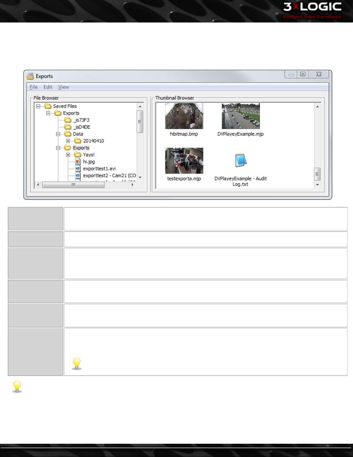
5.4 Export File Browser
The Export File Browser provides a thumbnail file browser for exported video footage and still shots. File navigation is similar to Windows Explorer. To open the Exports window, select the Export File Browser option from the tools drop-down menu in the main VIGIL
Server window.
Open a File
Open in External
Application
Copy a File
Delete a File
Copy a Folder
Delete a Folder
Double-click the desired file in the File Browser or Thumbnail Browser. This will open the file using the
default program as configured in the Windows file associations. VIGIL Server includes an internal viewer for
.BMP and .JPG files.
Right-click the desired file in the File Browser or Thumbnail Browser and select Open in External Appli-
cation. This will open the file using the default program as configured in the Windows file associations.
Right-click the desired file in the File Browser or Thumbnail Browser and select Copy item(s). This will
open the Select Destination window that allows you to save another copy of the file to an export des-
tination. You can also use the menu to copy a file by selecting the file and going to File | Copy item(s). To
select multiple folders, hold down the Ctrl key while selecting.
Right-click the desired file in the File Browser or Thumbnail Browser and select Delete item(s). You can also
use the menu to delete a file by selecting the file and going to File | Delete item(s). To select multiple folders, hold down Ctrl while selecting.
Right-click on a folder in the File Browser and select Copy item(s). You can also use the menu to copy a
folder by selecting the folder and going to File | Copy item(s). To select multiple folders, hold down Ctrl
while selecting.
Right-click on a folder in the File Browser and select Delete item(s). You can also use the menu to delete a
folder by selecting the folder and going to File | Delete item(s). To select multiple folders, hold down the
Ctrl key while selecting.
Note: Only empty folders can be deleted.
-32-
Note: For export folders to show in the browser, at least one export destination must be configured in Settings | Media
Drives tab | Export Destinations.
©2014 3xLOGIC Inc. | VIGIL Server - User Guide
Page 42

5.5 Alarms
The Alarms tool provides a listing of alarm events and allows quick playback of alarm footage. To open the Alarms window, select
Alarms from the Tools menu in the main VIGIL Server window.
Note:If Popup Alarm Screen is enabled in the settings, the Alarms window will automatically display in response to an alarm
event.
Alarms are listed in a tabular form with the camera number, camera name, alarm type, and alarm time. New alarms that have not
yet been acknowledged are red whereas acknowledged alarms are yellow.
Search
Alarms
Acknowledge Acknowledges the selected alarm and changes its highlighted color to yellow.
Acknowledge
All
Clear Clears the selected alarm from the Alarms window.
Clear All Clears all alarms from the Alarms window.
Suppress
Live Loads live video footage of the camera that corresponds to the selected alarm in the Live Viewer.
Playback
In the alarm right-click menu all of the above features are available as well as the Export Image feature. Once an alarm thumbnail
has been opened the Export Image feature will become available. When selected, the Select Destination window displays where the
user can choose an export destination to save a copy of the thumbnail image.
Search for cleared alarms.
Acknowledges all visible alarms and changes their highlighted color to yellow.
Opens the Suppressed Alarm window where alarms can be suppressed so that no new notifications from the sup-
pressed alarm will display until the alarm suppression expires or is deleted.
Plays back the video footage for the selected alarm. The playback footage will begin at the alarm Start Time and
end at the alarm End Time.
©2014 3xLOGIC Inc. | VIGIL Server - User Guide -33-
Page 43

5.6 Preview Alarms
Click on the thumbnail icon in the Preview column to show a thumbnail snapshot image of the alarm event. Click on the expanded
thumbnail to minimize it.
The grayscale thumbnail icon represents a thumbnail that has not yet been viewed. Click on the icon to view
the thumbnail.
The colour thumbnail icon represents a thumbnail that has been viewed, but has been minimized.Click on the
icon to open the thumbnail.
The grayscale thumbnail icon with a yellow exclamation point represents a thumbnail display attempt where
no thumbnail was currently available. For example, if the minute of video footage was still in process of being
written on the VIGIL Server system. Click on the thumbnail again after a moment to retry the thumbnail display request.
The alarm thumbnail snapshot displays the first frame of the alarm footage.
5.7 Suppress Alarms
While an alarm is suppressed, no new notifications from the suppressed alarm will display until the alarm suppression expires or is
deleted. While the alarm is suppressed, the Suppressed Alarms title bar flashes as a reminder that there are suppressed alarms.
Right-click on an alarm and select Suppress to open the Suppressed Alarm
configuration window. Click the Suppressed Alarms title bar to expand or
collapse the Suppressed Alarms window. In this window, Suppressed
Alarms can be added, edited, or deleted.
-34-
©2014 3xLOGIC Inc. | VIGIL Server - User Guide
Page 44

5.8 Search Alarms
Click to open the Search Alarms window where a variety of criteria can be used to search for an alarm event.
Click Search to search for all alarm events on the system. The results can be narrowed down with the following options.
From/To Check the From and/or To box and enter the time range to search for alarm events.
Alarm Type Check this box and select an alarm type to search for from the drop-down menu.
Alarm Check this box and enter an alarm number to search for.
Camera
Number
Reset Resets the search criteria to default.
Search Searches for alarm events that match the search criteria.
Live Loads the live video feed of the camera that corresponds to the selected alarm in the Live Viewer.
Playback
Prev Navigates to the previous page
Next Navigates to the next page
Check this box and enter a camera number to search for.
Plays back the video footage for the selected alarm. The playback footage will begin at the alarm Start Time and
end at the alarm End Time.
©2014 3xLOGIC Inc. | VIGIL Server - User Guide -35-
Page 45

5.9 Exporting with VIGIL Archive
To export footage and other surveillance
data(audio, POS/ATM data, user audit data)
from your VIGIL Server using VIGIL Archive,
select VIGIL Archive from Tools in the main
toolbar or by clicking the context arrow
from the Tools button in the icon menu toolbar and selecting VIGIL Archive from the
drop-down menu.
By default, all footage and all data from
the selected time range on all active cameras will be exported. Click on Advanced to
choose cameras and data types to be
exported.
Select a date and time range, and click
Next. Select a destination for your exports
and click Export to begin exporting your
footage and data. You can continue to work
in VIGIL Server while Archive exports your
data or you may watch Export progress via
the VIGIL Archive window. When the Export
has completed, you may exit VIGIL Archive.
Your files will now be present in the chosen
export destination.
Select a date and time range, and click
Next. Select a destination for your exports
and click Export to begin exporting your
footage and data. You can continue to work
in VIGIL Server while Archive exports your
data or you may watch Export progress via
the VIGIL Archive window. When the Export
has completed, you may exit VIGIL Archive.
Your files are now ready for import to a
VIGIL Review Station.
-36-
©2014 3xLOGIC Inc. | VIGIL Server - User Guide
Page 46

6 Reports
6.1 Client Connections
The Client Connections window displays a list of current con-
nection activity from other applications, for example VIGIL
Client stations. To open the Client Connections window,
select the Client Connections option from the Tools icon
drop-down menu in the main VIGIL Server window. You can
also double-click the Client Connections status bar.
The table provides the following information: the client’s
remote host name or IP address, the remote host connection
port, the locally connected port and the last activity time of
the connection.
Update Frequency- Adjusts the update frequency of the
table every set amount of seconds entered in the corresponding box.
6.2 Network Log Analyzer
The Network Log Analyzer provides a simple way to check for network activity of VIGIL software. It will log IP addresses and VIGIL
user names of all connections made. To open the Network Log Analyzer, select Tools from the main menu bar and select Network
Log Analyzer.
6.3 Audit Log Analyzer
The Audit Log Analyzer provides a way to analyze, search and monitor various errors and general information for the VIGIL Server
software. Essentially, it allows you to search the logs by using a variety of criteria such as date/time, error code, IP address, or module. To open the Audit Log Analyzer, select Tools from the main menu bar and select Audit Log Analyzer.
©2014 3xLOGIC Inc. | VIGIL Server - User Guide -37-
Page 47

7 Video and Audio Recorder Controls
7.1 Video Recorder Controls
The Recorder Controls window allows you to control which cameras are recording footage. It also provides a quick summary of the
camera configuration. To open the Recorder Controls window, click the Recorder button in the main VIGIL Server icon toolbar.
Start Record-
ing
Stop Record-
ing
Camera Setup
Close Window Closes the Recorder Controls window.
Type/Address/ The Type/IP address/Port/URL of the network camera.
-38-
Starts recording footage for the selected camera.
Stops recording footage for the selected camera.
Opens the Camera Setup tab in the VIGIL Server Settings window. The camera selected in the Recorder Controls
window will be automatically selected in the Camera Setup tab.
Network cameras are represented by a network symbol over or underneath the camera icon.
Camera is currently recording. If the camera features hardware PTZ, it will appear as
Camera is currently stopped.
Camera is disabled.
©2014 3xLOGIC Inc. | VIGIL Server - User Guide
Page 48
Port/URL
The drive information section gives the current status of the VIGIL Server data drives. The information includes
the percentage of free space on the drive, physical path of the drive, and the physical free/total space of the
drive. The icons to the left of the drives indicate their status:
Drive Infor-
mation
Configured drive
Currently recording on this drive
Drive warning
Drive error, contact your system administrator
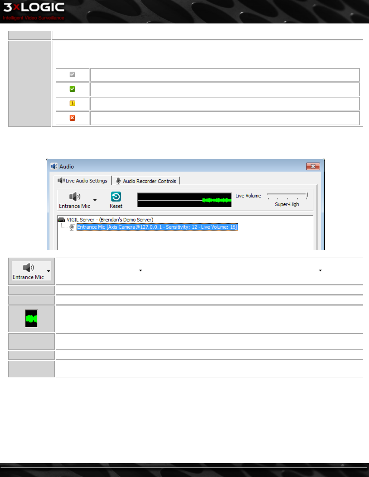
7.2 Live Audio Settings
The Live Audio Settings window is used to adjust recording levels and monitor live audio.
Cycles through the available audio channels to monitor live audio. Select the channel to monitor by clicking on
the channel name or use the button to select a channel. To disable live monitoring, use the button to
select the Stop Monitor option.
Reset Resets the volume and sensitivity levels for the selected live audio channel.
Close Window Closes the Live Audio Settings window.
The audio visualization graph provides a visual representation of the audio information currently being recorded.
Keep an eye on this graph while modifying audio sensitivity and live volume settings.
Sensitivity
Live Volume Use the slide bar to adjust the live volume of the selected audio channel.
Capture Vol-
ume
Controls the sensitivity of the audio detection. Higher sensitivity will trigger audio recording at the slightest
noise while lower sensitivity will only trigger audio recording with louder noise.
Use the slide bar to adjust the live volume of the selected audio channel. (Only available on VIGIL Server systems using a capture card.)
©2014 3xLOGIC Inc. | VIGIL Server - User Guide -39-
Page 49
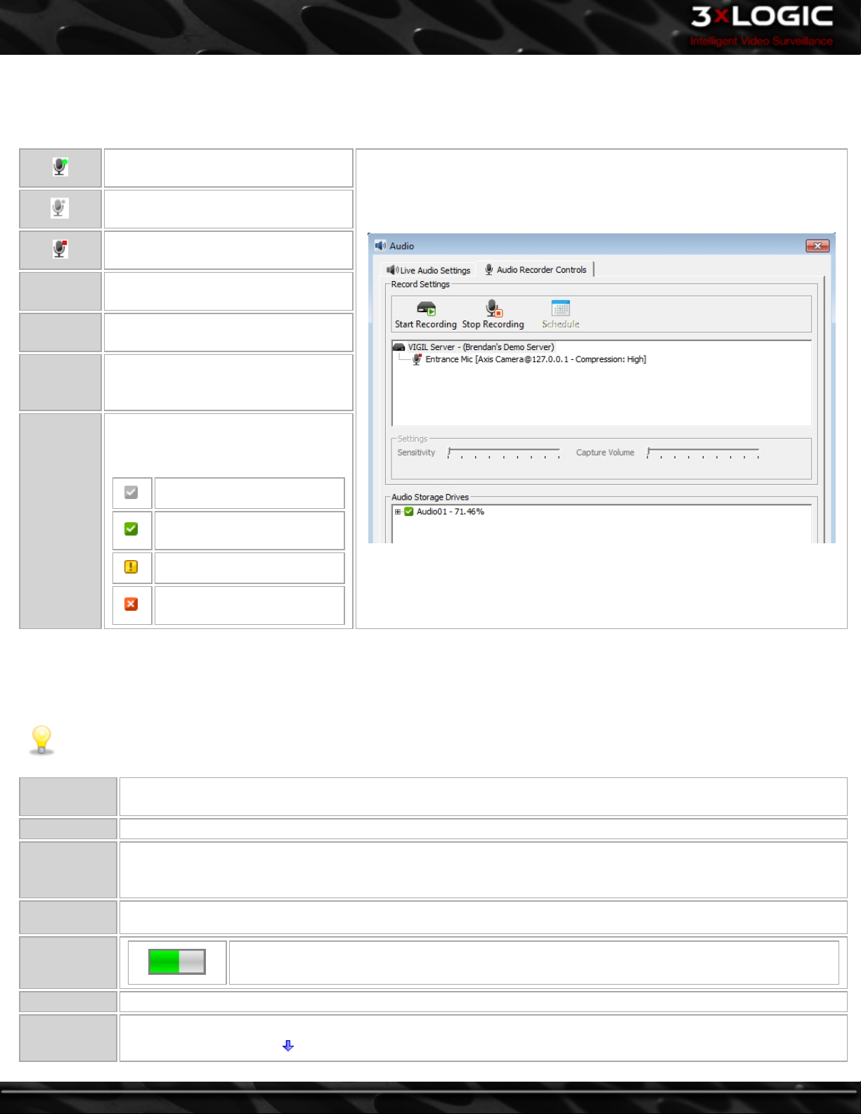
7.3 Audio Live/Recorder Controls
The Audio Recorder Controls window is used to view audio channel status and to manually stop or start the recording of specific
audio channels.
The channel is currently recording
audio.
The channel is set to record, but
there is no audio detected.
Audio recording has been stopped on
this channel.
Start
Recording
Stop
Recording
Schedule
Starts recording audio on the selected
channel.
Stops recording audio on the selected
channel.
Opens the schedule calendar where a
recording schedule can be configured.
The drive information section gives
the current status of the VIGIL Server
audio storage drives:
Drive Infor-
mation
Configured drive
Currently recording on this
drive
Drive warning
Drive error, contact your
system administrator
7.4 Chat
VIGIL Server and Client include a chat feature to speak or write back and forth between VIGIL Clients connected to VIGIL Servers.
The Chat session is initiated by the VIGIL Client only and can be used to communicate vocally or in text.
Note: For voice chat to be available and function correctly, an audio channel for chat must be configured in the Audio tab.
Enabling
Audio
Disconnecting Right-click on the site name and select Disconnect.
Hands Free
Right-click on the site name in the right pane of the chat session and select Audio. This will initialize the audio for
the chat session. Uncheck Audio to stop all audio.
Check Hands Free for VIGIL Chat to automatically detect the volume level and only send voice when sound
reaches a specific volume. Uncheck Hands Free to use the Talk button to manually start and stop sending voice
data.
Talk When Hands Free is unchecked, click Talk to send voice data. Unclick Talk to stop sending voice data.
Voice Detec-
tion Graphs
Send Text Sends a typed message. Type text into the text-box and click Send Text.
Use the slide bar to adjust the chat audio sensitivity. To the left is less sensitive, to the right is more
Sensitivity
sensitive.Use the down button to expand the Controls section.
-40-
The voice detection graphs provide a visualization of voice data detected in the chat session.
©2014 3xLOGIC Inc. | VIGIL Server - User Guide
Page 50
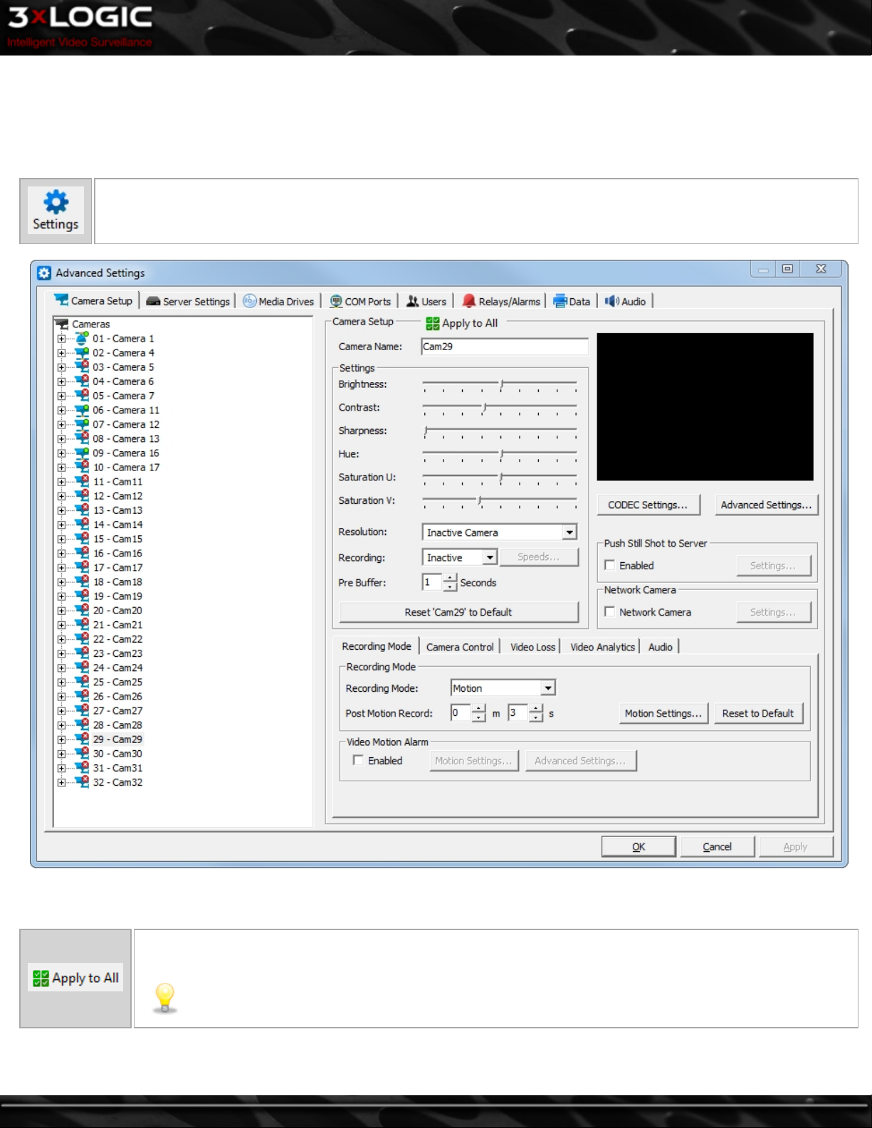
8 Settings – Camera Setup Tab
VIGIL Server is a diverse software application that interfaces with a wide variety of hardware configurations. A comprehensive set of
customization controls is available to configure the VIGIL Server as required. This section will describe the available settings in
detail.
Opens the VIGIL Server Settings window, which can also be accessed via the main menu:Tools | Settings. When mak-
ing changes, click the Apply button to save and continue making changes, or click OK to save and return to the main
VIGIL Server window. Click Cancel to close the settings without saving changes.
The Camera Setup Settings allow configuration of the camera image, resolution, recording speed, buffering and CODEC. Network
cameras are also enabled under the Camera Setup tab.
Click the Apply to All button at the top of the window to apply the same settings to all cameras. Settings that
will be applied to all cameras will be indicated by BOLD headings.
Note: Only changes made after clicking Apply to All will be applied to every camera.
©2014 3xLOGIC Inc. | VIGIL Server - User Guide -41-
Page 51
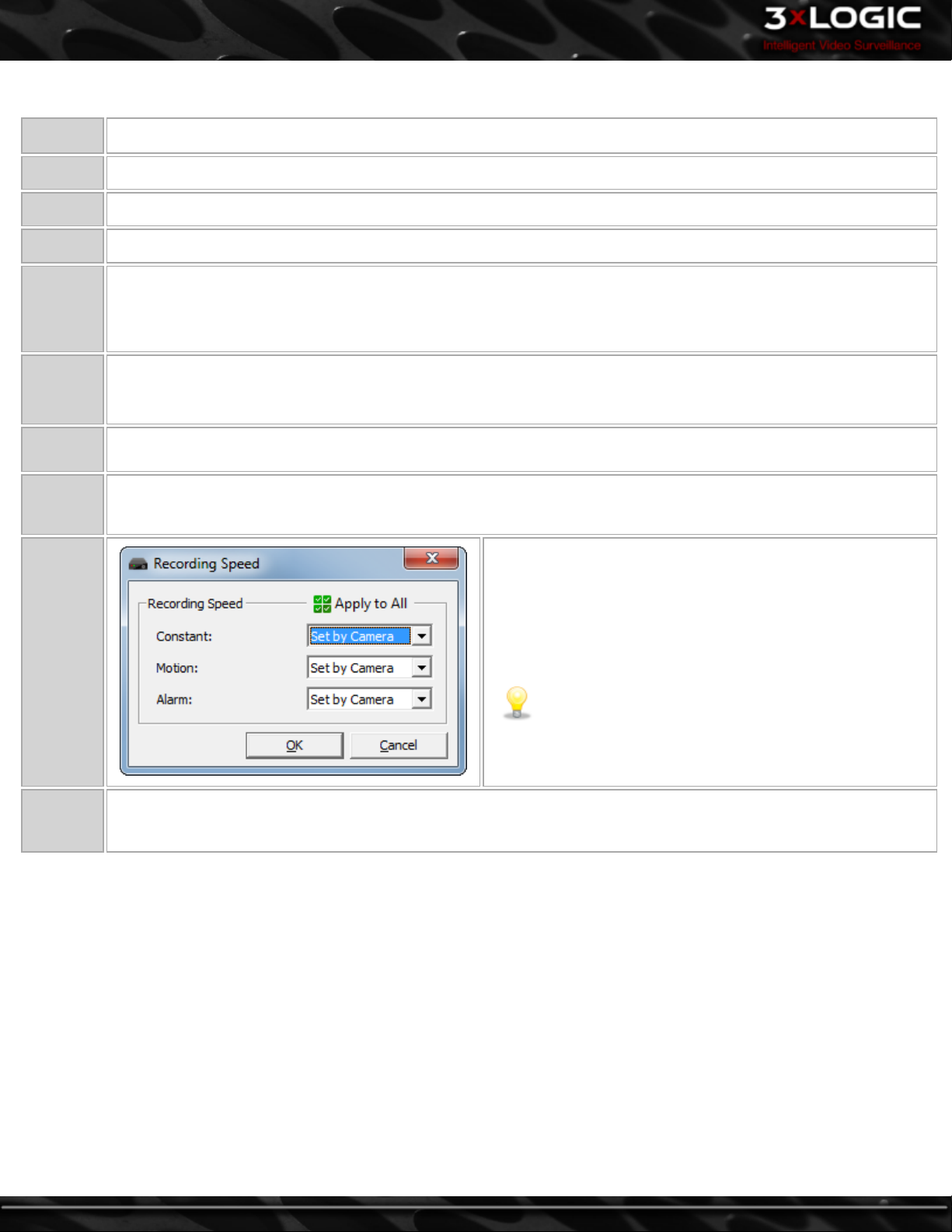
8.1 Camera Setup Tab - Camera Settings
Brightness Adjusts the brightness of the video footage.
Contrast Adjusts the contrast of the video footage.
Sharpness Adjusts the sharpness of the video footage.
Hue Adjusts the color of the video footage.
Saturation
U and V
Resolution
Recording
Pre Buffer
Speeds
Adjusts the U and V color difference signals used in YUV color format for the video footage. Note that not all cameras use a YUV color format, in which case, adjusting the Saturation U slider will adjust the color saturation while the
Saturation V slider will have no effect.
Select a recording resolution from the drop-down menu. Options range from 352x240 to 704x480 resolution. If a network camera is enabled on the channel, this option will not be available.
Use the drop-down menu to enable or disable recording of the selected camera. If the selected camera is not available, Inactive will be displayed here.
The number of seconds of footage to record prior to a motion detection or alarm event. For JPEG Camera streams the
recommended setting is 1. For H264 Camera streams it is recommended to set the pre buffer to the key frame rate.
Opens the Recording Speed window. The recording speed can
be set individually for Constant, Motion and Alarm Recording
Mode. Use the drop-down menu to select the desired number of
frames per second (fps).
Note: Network cameras will often record and play
back at a slower rate than what was set in the Recording Speed window, depending on the bandwidth and
camera.
Reset
‘Cam#’ to
Default
Returns the camera settings to their default values.
8.1.1 Advanced Settings
In the Advanced Settings window, the cameras are grouped into Bank tabs that represent the physical camera banks in the VIGIL
Server. This allows the user to maximize the capture resolution and recording speeds for each camera bank. When the number of FPS
is changed in the Advanced Settings window, it is applied to all recording modes.
-42-
©2014 3xLOGIC Inc. | VIGIL Server - User Guide
Page 52
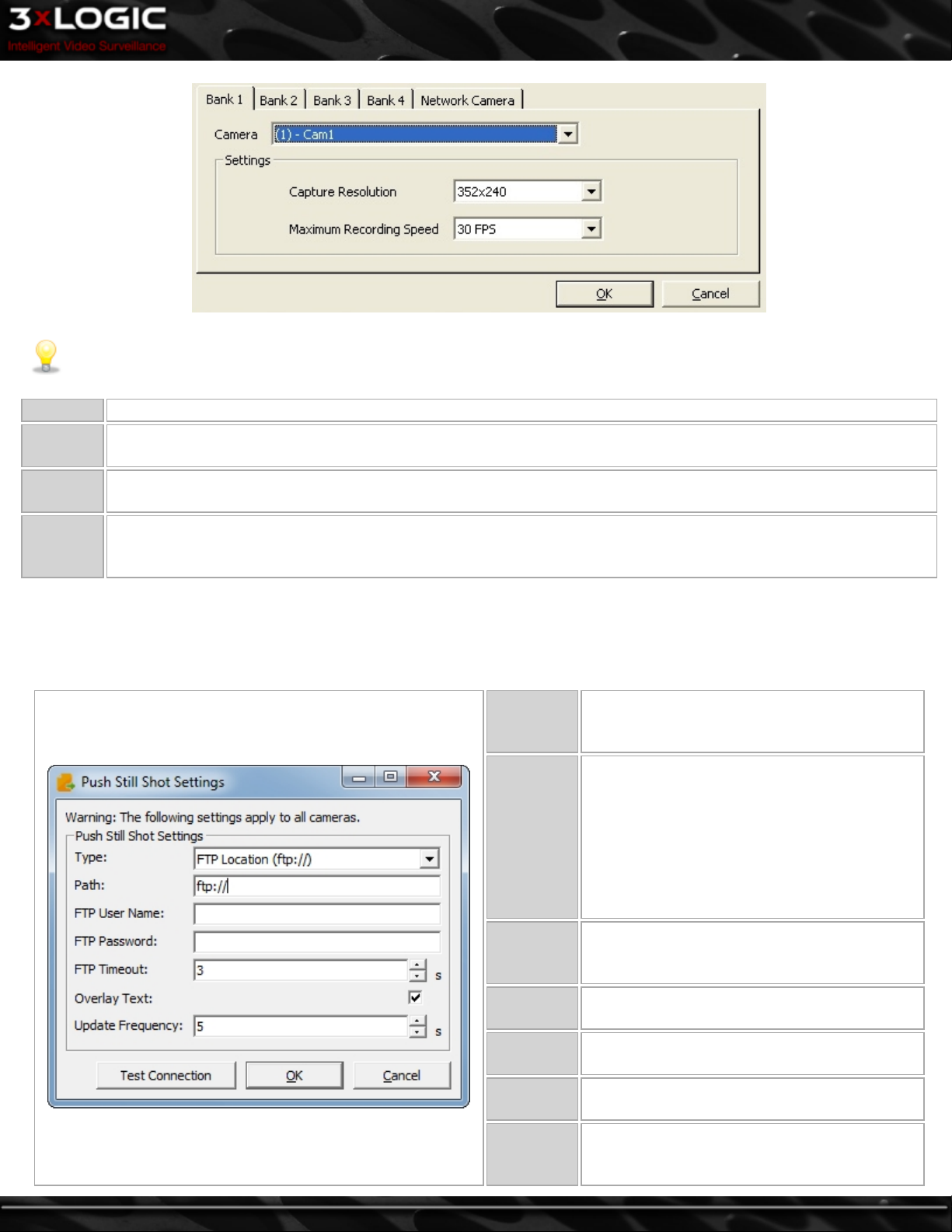
Note:The number of banks and the cameras in each bank is determined by the capture card installed, which cannot be con-
figured. There are many possible layouts of banks and channels per bank.
Camera Select a camera number within the current Bank tab to change its settings.
Capture
Resolution
Recording
Speed
Network
Camera
Tab
Select the desired recording resolution from the drop-down menu.
Select the desired number of frames per second. Each bank has a set amount of FPS that can be set to its cameras.
Values will change depending on the recording speeds for other cameras within the same bank.
Network cameras are automatically detected and the analog feed is disabled for that camera number. Network camera speeds are independent of other cameras and do not change the maximum allowable FPS for cameras belonging to
the same camera bank.
8.1.2 Push Still Shot to Server
The Push Still Shot to Server Settings window allows a still shot from the camera to be copied periodically to another location. To
enable this feature for the selected camera, check the Enabled box. Click the Settings… button to configure the destination for the
still shots. This applies to all cameras.
The type of storage location. Options are FTP
Type
Location, Windows Network Share and Local
Drive.
The path where the image files will be
uploaded (only pre-existing directories can be
used).
Path
FTP User
Name and
Password
FTP Time-
out
Overlay
Text
Update
Frequency
Test Con-
nection
Local Directory:C:\Images.
Network Directory: \\C-
omputerName\SharedFolder.
FTP site: ftp://ftpserver/folder.
If required, enter the user name and password
for the FTP Site.
The time to wait in seconds before a timeout
occurs.
Check this to have an overlay of the camera
name, date, and time on the still shot.
The frequency, in seconds, at which the image
file is uploaded to the specified path.
Tests the connection using the specified parameters. A window will display a message stating
whether the connection is successful or not.
©2014 3xLOGIC Inc. | VIGIL Server - User Guide -43-
Page 53

8.2 CODEC Settings
The CODEC Settings window allows advanced configuration of the recording CODEC used for storing video footage recorded on
analog cameras.
Opens the CODEC Settings window.
Click the Apply to All button at the top of the window to apply the same CODEC settings to all cameras. Settings
that will be applied to all cameras will be indicated by BOLD headings. Only changes made after clicking Apply
to All will be applied to every camera.
Select between AZTECH and MPEG encoding.
CODEC
Show Preview Plays the camera footage as it encodes the preview window with the settings that are configured.
-44-
Note:Normally, two video encoding CODECs are currently available for recording video footage:
AZTECH and MPEG4 CODECs. However, some models support Hardware CODECs, which have slightly different customization options.
©2014 3xLOGIC Inc. | VIGIL Server - User Guide
Page 54
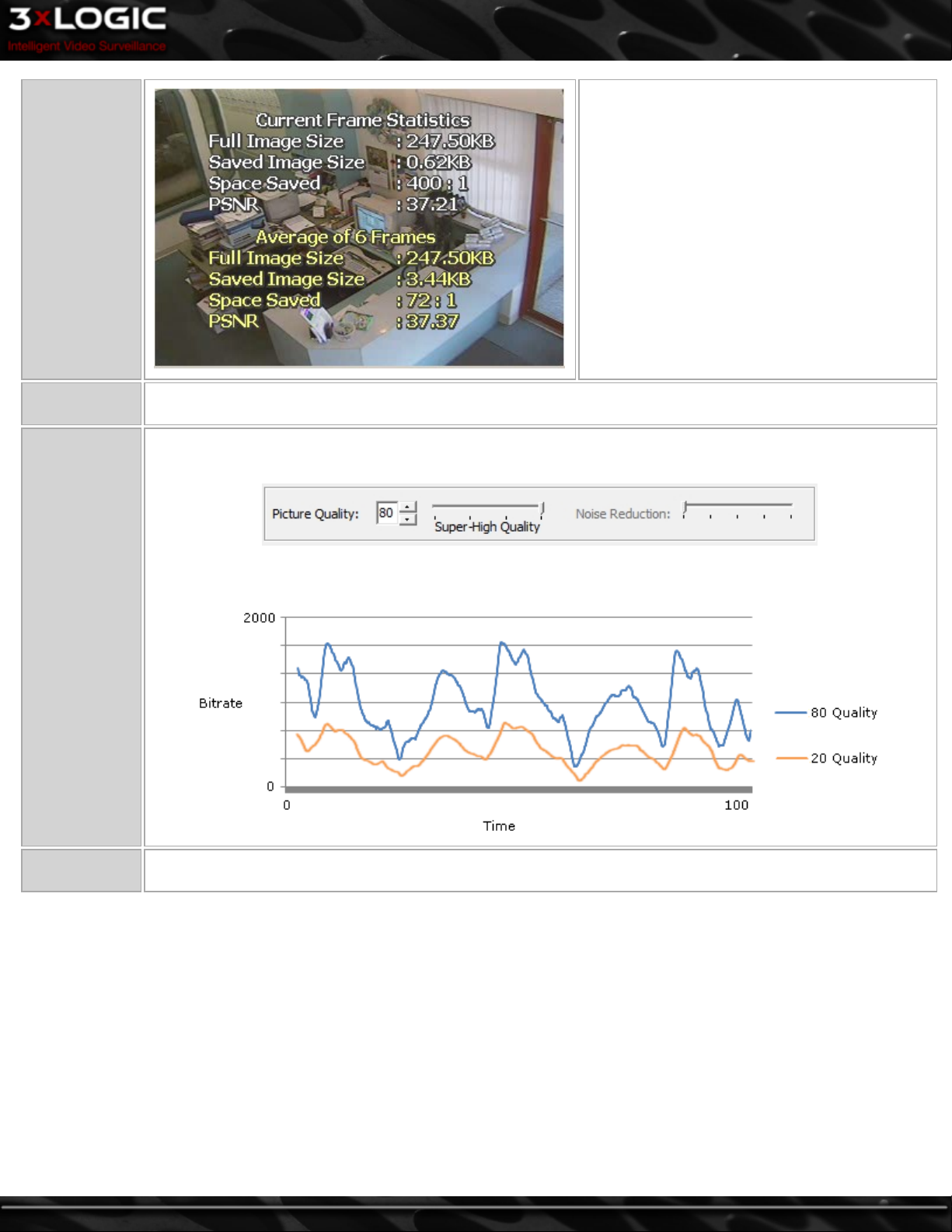
Show Statistics
If Show Preview is enabled, Show Statistics can
also be clicked to display compression statistics
on the preview window.
Reset to
Default
Picture Quality
Resets the CODEC settings to their default values.
Adjusts the picture quality of the recorded video. Higher quality video will occupy more space on the video storage drive. The arrows, the text box, or the slide bar can be used to change the value.
How Picture Quality Can Affect Total Disk Usage:
Noise Reduc-
tion
Adjusts the level of video noise for grainy video.
©2014 3xLOGIC Inc. | VIGIL Server - User Guide -45-
Page 55
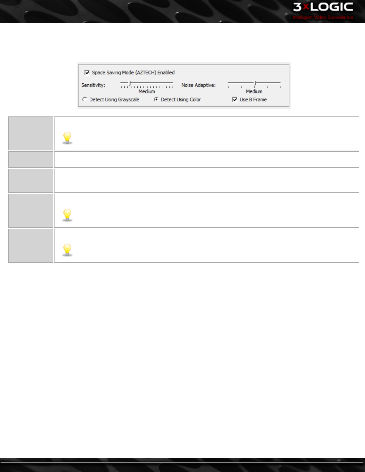
8.2.1 AZTECH™ CODEC Settings
The AZTECH™ CODEC is the default CODEC for most systems. To switch the recording CODEC to AZTECH, select the AZTECH option
from the CODEC drop-down menu.
Space Saving
Mode (AZTECH)
Enabled
Sensitivity
Noise Adaptive
Detect Using
Grayscale/
Color
Use B Frame
Enables advanced compression technology to decrease the file size of recorded footage.
Note:This is a CPU intensive setting.
Adjusts the threshold used by the CODEC to identify areas of change between frames. The higher the sensitivity,
the smaller a change is encoded.
Adjusts the noise threshold used by the comparison algorithm when determining whether a block contains a
change. When this value is increased, more noise is allowed in the block without triggering change for that
block. This feature does not decrease noise in an image.
Determines whether grayscale or color will be used to detect changes.
Note:Color detection is a CPU intensive setting.
Uses bi-directional frames to decrease the file size of recorded footage.
Note:This is a CPU intensive setting.
-46-
©2014 3xLOGIC Inc. | VIGIL Server - User Guide
Page 56
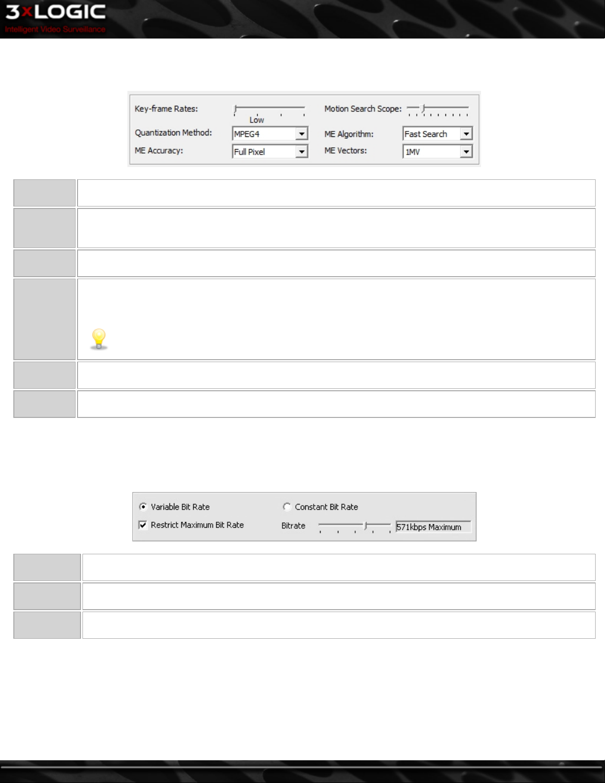
8.2.2 MPEG4 CODEC Settings
To switch the recording CODEC to MPEG4, select the MPEG4 option from the CODEC drop-down menu.
Key-frame
Rates
Motion
Search
Scope
Quantization
Method
ME Accuracy
Sets the number of key-frames recorded per second. The higher the value, the greater the data space needed for
recording, but the higher the quality of the video.
Changes the size of the regions used to detect motion.
Selects the type of compression. H264 offers higher compression than MPEG4 but requires more CPU usage.
Motion Estimation Accuracy includes two options: Full Pixel and Half Pixel. Full Pixel checks for motion comparing
differences of full pixels. Half Pixel will check for motion using an interpolation method that detects finer movements.
Note: Half Pixel is a CPU intensive setting.
ME Algo-
rithm
ME Vectors
The Motion Estimation Algorithm changes the shape of the area used for motion detection and includes two
options: Full Search and Fast Search. Fast Search will save CPU time but Full Search is more accurate.
Sets the number of vectors tested for motion from 1 to 4. The greater the number, the more CPU processing is
required.
8.2.3 Hardware CODEC Settings
Depending on the VIGIL Server model, it may use Hardware CODEC recording, which has slightly different customization options. For
some types of cards the CODEC used can be changed in the VIGIL Server Settings | Hardware Tab via the Hardware CODEC dropdown box.
Variable Bit
Rate
Constant Bit
Rate
Restrict Max-
imum Bit Rate
The default setting of Variable Bit Rate allows the encoder to change its recording bit rate automatically as
required. This option offers the best combination of file size and visual quality.
Changes a variable bit rate into a constant bit rate. A setting of Constant Bit Rate with a very high bit rate
selected will provide the maximum video quality settings, although this is at the expense of storage space.
Sets a hard limit on the maximum quality that can be recorded. Use the slide bar to select the desired maximum
bit rate.
©2014 3xLOGIC Inc. | VIGIL Server - User Guide -47-
Page 57

8.3 Network Camera Settings
VIGIL Server is able to receive video from one or many network
cameras connected to a LAN or WAN. VIGIL Server currently
supports several types of network cameras.
To setup or change a network camera, check the Network Cam-
era box, then click the Settings… button. This will open the
Network Camera Settings window.
Note:The Network Camera feature disables the phys-
ical camera input on the video capture card.
The type of network camera.
Warning: Due to the substantial overhead associated with HTTP, attempting to record HTTP camera
Type
Address
Web/Camera
Settings
Data / RTSP
Port
Camera
Number
URL Set this to the camera URL, if applicable.
… Opens additional configuration options for some cameras.
Stream Type
The IP or HTTP address of the camera. It is not necessary to include http:// at the beginning of the HTTP
address.
Connects to the camera’s web interface to make changes to the camera’s internal settings. For some camera
types, this will open a Camera Settings window instead of connecting to the web interface.
The network ports used to connect with the camera.
Some Network Camera types also support encoders. Select the camera number on the encoder to use for this network camera.
Select the video stream type for the camera: MPEG4, JPEG, or H264. Some kinds of network cameras can only
have one stream type for all cameras of its kind.
feeds over the Internet is not recommended. High speed LAN or WAN configurations are recommended
for HTTP camera use. If the network bandwidth is insufficient, the message Signal Loss will be displayed
in place of the live feed.
-48-
©2014 3xLOGIC Inc. | VIGIL Server - User Guide
Page 58

Timeout
User/Password The user name and password to connect to the camera. The default values are automatically entered.
AZTech Recom-
press
Fast Decom-
pression
DIO (Digital
Input/Output)
Audio Record-
ing
Camera Con-
trol
Audio Talk If the Network Camera supports Audio Talk, enable the checkbox to enable audio talk.
Sub Stream
Default Set-
tings
The number of seconds to attempt to connect to the camera before timing out. If the timeout is reached, Signal
Loss displays in the Live Viewer window.
This will recompress the image using AZTECH™ codec.
Note: AZTech Recompression is a CPU and RAM intensive process.
If the JPG image provided by the HTTP camera supports fast decompression, select this option to significantly
reduce the number of CPU cycles needed for rendering the network camera feed.
Not all network cameras support fast decompression. Disable Fast Decompression if the image does not display or
appears distorted when this feature is enabled.
If the Network Camera supports DIO, enable the checkbox to automatically add the camera as a DIO device.
If the Network Camera supports audio, enable the checkbox and enter a Name for the audio channel to automatically add the camera as an audio device.
If the Network Camera supports PTZ(Pan/Tilt/Zoom), enable the checkbox to automatically set the PTZ type.
Enable this checkbox to make the Sub Stream from the Network Camera available to applications that connect
to the Server such as VIGIL Client.
Changes the network camera settings to their default values.
©2014 3xLOGIC Inc. | VIGIL Server - User Guide -49-
Page 59

8.3.1 Network Camera Type - VIGIL Server
Another VIGIL Server can be connected in the same way you would connect to a Network Camera. This will display any camera that
the VIGIL Server receives and allows you to relay analog video from one recording VIGIL Server to another.
To set up this configuration, select the VIGIL Server type in the Network Camera window. The recommended settings for this setup
are:
Address IP Address of the VIGIL Server.
Port Live Video Port, default 22802.
Camera Number The camera input number on the remote VIGIL Server to be used.
User/Password The username and password used to log into the remote VIGIL Server, if applicable.
ONVIF and PSIA Network Camera Types
ONVIF and PSIA are interoperability standards for IP based Network Cameras. As long as a camera supports either of these standards,
it can be configured with this standard instead of the brand specific standard. ONVIF is the predominate standard currently being utilized by manufacturers. When configuring an ONVIF supported camera through the Network Camera Settings, the ONVIF device manager is opened.
-50-
©2014 3xLOGIC Inc. | VIGIL Server - User Guide
Page 60

ONVIF Device Manager
After selecting the ONVIF type in your Network Camera settings, the
Web Settings button will change to Detect Cameras. Select this option
to proceed to the ONVIF Device Manager. You will first be met with a
small notification pictured below while the ONVIF Device Manager loads.
After a few seconds, the ONVIF Device Manager will boot and you will be met with the interface pictured below-right.
The ONVIF Device Manager
offers a large selection of settings to help configure all of
your cameras using the ONVIF
standard to your personal preferences. The manager consists
of three panes. The left pane is
the Device List which hosts a
list of all available camera
using the ONVIF standard.
Select your desired camera and
click Save to VIGIL to display
that camera within VIGIL
Server. The middle pane hosts
a list of camera configuration
options and the third(right)
pane is where you manually
configure the options you have
chosen to configure.
Configuring Imaging and Stream Settings in the ONVIF Device Manager
To edit stream and image
settings for a selected
camera, select Video
Streaming or Imaging Settings. See Section 8 - Network Camera Settings for
more info on camera settings.
Click Apply to save settings.
©2014 3xLOGIC Inc. | VIGIL Server - User Guide -51-
Page 61

Saving To VIGIL
After returning to the main
screen with the desired camera
selected, click Save to VIGIL to
save the feed to a VIGIL Server
camera channel. You will
receive the prompt pictured
right where a user can choose
which stream profiles to use in
VIGIL.
Click OK to save the camera to
VIGIL.
Multiple Cameras Stitched Together Into One Image
Designed for use with video analytics on DRX systems, the Network Camera, Multiple Cameras option is used to configure multiple
analog video feeds as one video image. This is used to piece together camera images directly beside one another into one large
image.
There must be the correct amount of overlap between the images to prevent fluctuation of the person size as a person moved
between images.
USB Camera
VIGIL Server can record from USB Cameras connected to the Server. The USB camera drivers need to be installed for VIGIL Server to
be able to detect the camera.
-52-
©2014 3xLOGIC Inc. | VIGIL Server - User Guide
Page 62

8.4 Recording Mode Tab
8.4.1 Recording Modes
There are four Recording Mode options encompassing a full range of recording possibilities. These modes are accessible by selecting
the appropriate option from the Recording Mode drop-down menu.
Constant Always recording, 24 hours 7 days a week.
Records based on a schedule. The easy to use graphical interface provides a full overview of a week’s schedule in 15-
Schedule
Motion
Alarm
Only
minute intervals. This mode offers full control over recording times and any combination of constant or motion controlled recording modes.
Records only when motion is detected. Full configuration over motion area, amount of motion, size of motion and post
motion recording time makes this a very versatile recording mode.
Records in alarm mode when any alarm is detected. The alarms can be of any type including Video Analytics, Video
Motion, Digital Input and POS Alarms.
©2014 3xLOGIC Inc. | VIGIL Server - User Guide -53-
Page 63

8.4.2 Scheduled Recording
If Schedule is selected from the Recording Mode drop-down menu, the Schedule window will appear. To edit an existing schedule
click the … button to open the Schedule window. To modify a schedule, click the appropriate recording mode button (Const or
Motion), and then click-and-drag across a time slot. Areas that are blank (no color) have no recording modes defined for that time
and will not record any footage.
Note:The smallest time interval that can be used is a 15 minute period.
Const Sets or changes the section to Constant recording mode; these time periods are colored green.
Motion Sets or changes section to Motion recording mode; these time periods are colored blue.
HZoom+/- Expands and contracts the schedule horizontally; this allows for better precision in setting time periods.
VZoom+/- Expands and contracts the schedule vertically.
Move a time period Click and hold the Shift key, then click-and-drag the section.
Copy a time period Click and hold the Ctrl key, then click-and-drag the section.
Change record
mode
Change the
start/end time
Importing from
another camera
Viewing start and
end times of a sec-
tion
Deleting a time
period
Deleting a schedule Click the Clear All button to delete the entire schedule.
Apply Schedule To
All Cameras
Click a section of the schedule, and then click the appropriate button (Const or Motion) to change the
recording mode for that section.
Select the section by clicking on it and then click-and-drag the right or left edge of the section.
Select the camera from the Import From Camera drop-down menu, and then click Import. This will overwrite the current schedule.
Select the section by clicking on it. The start and end times of the section are displayed near the bottom
left corner of the Schedule window. Hover the mouse over any part of the section to display the time.
To select a section, click on it and then click Delete.
When marked, this checkbox will apply the created schedule to all cameras that have been set to Schedule
recording mode.
-54-
©2014 3xLOGIC Inc. | VIGIL Server - User Guide
Page 64
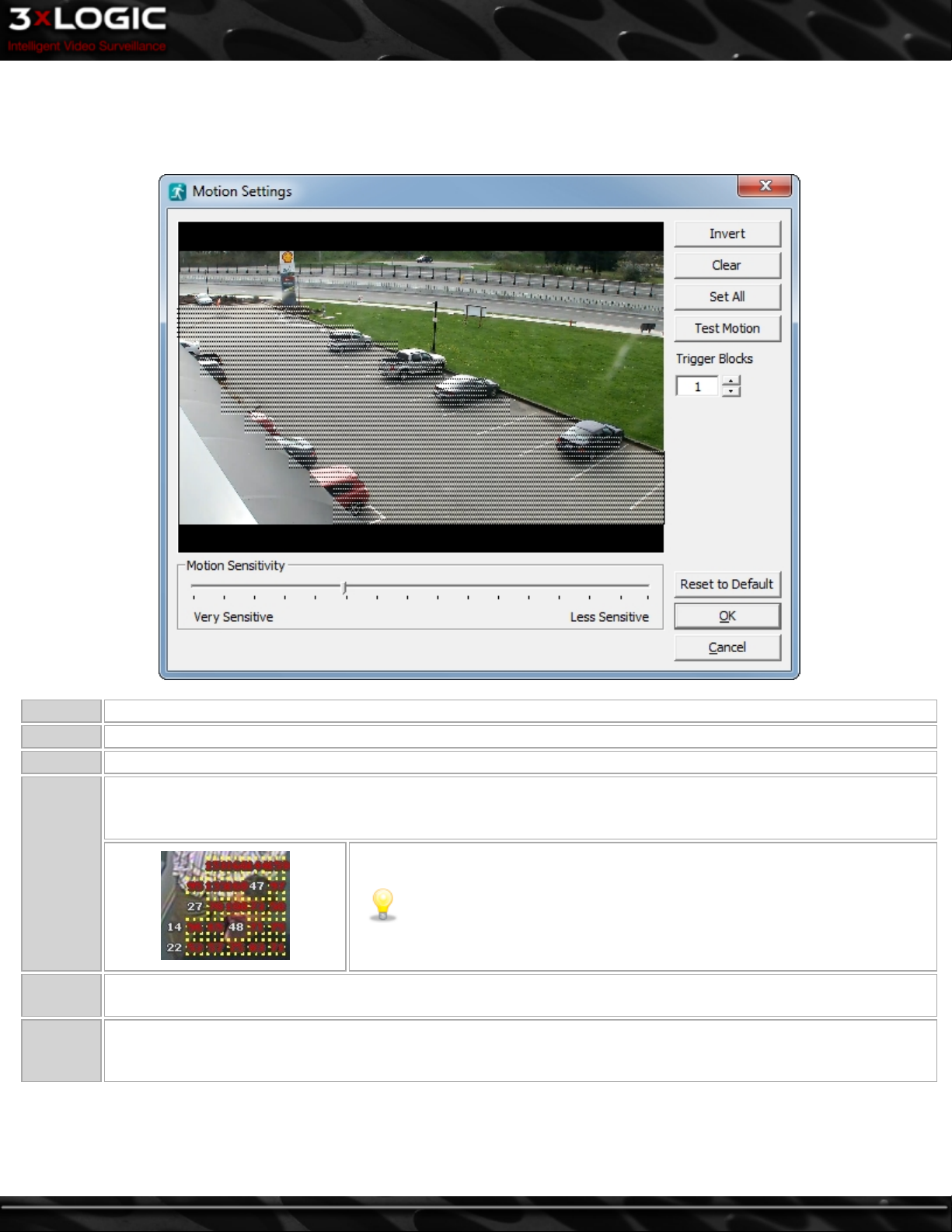
8.4.3 Motion Recording Settings
When recording in Motion mode, click the Motion Settings… button to access the Motion Settings window. Here you configure which
regions of the video image are to be used for motion detection. To do this, simply draw on the video. A semi-transparent overlay will
be drawn over the video; this marks the motion detection region. To clear a motion detection region, click and draw on it.
Invert Swaps masked and clear regions.
Clear Clears all masked regions.
Set All Masks the entire image.
When latched on, the preview window will display motion detection blocks and their real-time motion values overlaid
on masked regions of the video. When motion is detected based on the sensitivity, values are highlighted in yellow
with red text.
Test
Motion
Trigger
Blocks
Motion
Sensitivity
Determines how many motion blocks must meet the motion sensitivity requirement to trigger motion recording.
Adjust the Motion Sensitivity slider to control the amount of motion required to trigger recording. Use a very sensitive
setting to detect almost all motion, or a less sensitive setting to require only very large movements to trigger recording.
Note:The Trigger Blocks setting does not affect the motion test; the Test
Motion feature is designed to test the motion sensitivity only
©2014 3xLOGIC Inc. | VIGIL Server - User Guide -55-
Page 65

8.4.4 Video Motion Alarm
The Video Motion Alarm settings allow you to configure powerful motion detection alerts that include full control over motion quan-
tity, size, area, speed and direction of motion. In addition to the alarm itself, a wide variety of alarm notification settings are available. Video Motion Alarms can be used in conjunction with any other recording mode. For the basic configuration options See
"Motion Recording Settings" on page 55 .
Note:When Video Motion Alarm is enabled and a motion alarm is detected, the VIGIL Server will record in alarm mode
regardless of any other recording mode defined, and an alarm event will be triggered.
A motion vector is composed of two or more motion detection regions and one vector. It represents an object
moving through specific areas of the image in a set direction. If motion is detected in two of the regions in the
general direction indicated by the vector arrow, the Motion Alarm will be triggered.
Draws a motion detection region as an alternative to using the mouse and drawing by hand. You cannot draw
on a motion detection region to create a clear region.
Draw Region
Note:Regions with sides that are touching or overlapped are detected as one region. To use a motion
vector, you must have at least 2 motion regions that do not border each other.
Specify a direction of movement that will trigger a motion alarm; draw a direction by clicking and dragging
the mouse. An arrow will be drawn on the preview window.
Set Vector
Note:If there is no motion vector arrow specified, any of the selected regions will trigger a motion
alarm.
Clear Removes the applied motion vector.
Determines the speed required to trigger the alarm. Motion must be detected in two or more of the regions in
Motion Timeout
the desired direction within this time. If the object moves so slowly that it does not move from one region to
the next within the Motion Timeout period, then a motion alarm will not be triggered.
Example of Motion Vector
-56-
©2014 3xLOGIC Inc. | VIGIL Server - User Guide
Page 66
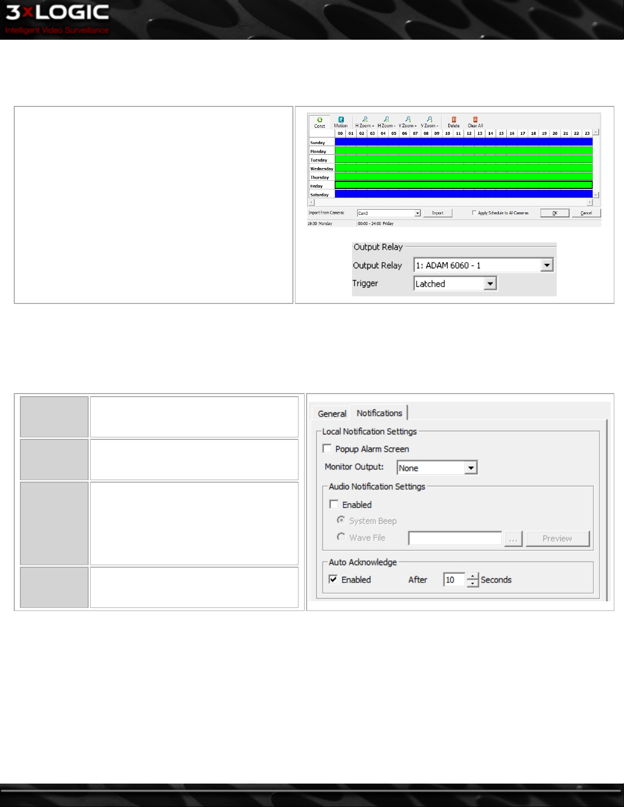
8.4.5 Video Motion Alarm Advanced Settings
The advanced settings include scheduling when the alarm is active, Output Relay Options, and Notification Settings.
General Tab
Schedule
Click the checkbox to enable a schedule for when the Video
Motion Alarm will be active. Click … to configure the
schedule.
Click and drag to set when the Video Motion Alarm is
active, marked in green. The schedule functions the same
as in Recording Mode Tab – Scheduled Recording.
Output Relay
Select an Output Relay to be triggered from the drop down
box. The trigger options are Latched (for the duration of
the alarm), or Momentary (2 seconds, regardless of alarm
duration).
Post Motion Record
Post motion recording time for Video Motion Alarms is set here and is independent of any other post motion recording settings. The
default is 3 seconds.
Notifications Tab
Local Notification Settings
Popup Alarm
Window
Monitor Out-
put
Audio Noti-
fication Set-
tings
Auto Acknowl-
edge
Select this option to have the Alarm window automatically displayed when a motion
alarm is triggered.
Select an analog output monitor to display
the triggered camera at the time of the
motion alarm.
Enables audio notification when a motion
alarm is triggered. Two audio notification
types are available:
System Beep - Sounds a system beep.
Wave File– Plays a WAV audio file.
Enables the automatic acknowledge for
Motion Alarm notifications after the specified number of seconds.
©2014 3xLOGIC Inc. | VIGIL Server - User Guide -57-
Page 67
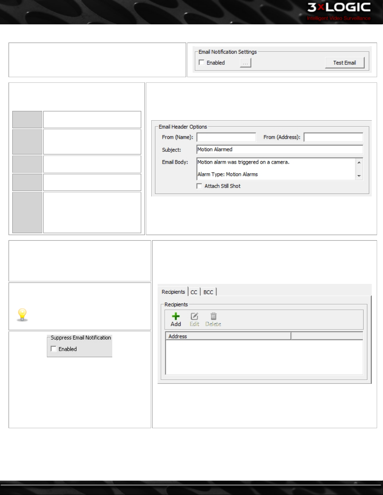
Email Notification Settings
When enabled, an email is sent to all recipients informing
them that a motion alarm has been triggered.
Click the Enabled check box to enable Email
Notifications and open the Email Settings win-
dow.
From
(Name)
From
(Address)
-
Subject -
Email
Body -
Attach
Still Shot
-
Recipients - These are the lists of recipients who
will receive Motion Alarm notifications. There
are three lists of recipients, direct recipients,
carbon copied recipients and blind carbon copied
recipients.
Test Email - Sends a test email based on your
notification settings and email configuration.
- The name of the entity that
will be sending the emails.
The email address of the entity
that will be sending the emails.
The text that will be the subject
line of the emails.
The text that will be included in
the body of the emails.
Allows a still image from that
camera to be attached to the outgoing email. The image is always
from the beginning of the motion
alarm event.
Note:For email to function properly, a
valid SMTP Server must be configured in
the VIGIL Server Settings tab.
This option, which will only work in conjunction
with enabling Popup AlarmScreen, will prevent a
flood of email alerts being sent out. It will only
send out one email alert until the alerts have
been acknowledged in the popup Alarm window.
If alerts have been set to Auto Acknowledge, it
will send out an email after each period of auto
acknowledgement has passed.
-58-
©2014 3xLOGIC Inc. | VIGIL Server - User Guide
Page 68
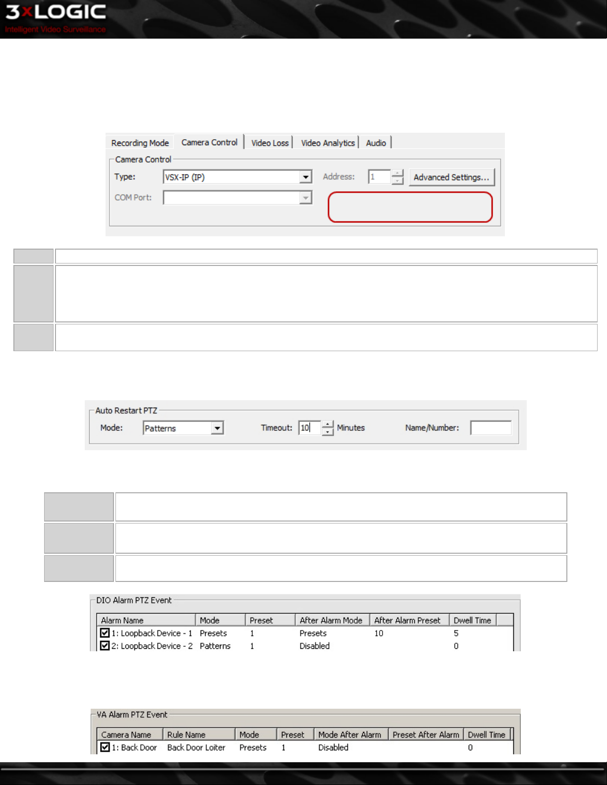
8.5 Camera Control Tab
Some PTZ cameras can be operated remotely by VIGIL Server. To configure a camera for remote control, click on the Camera Control tab. Select the camera type, the COM port and the address. These settings are determined by the camera itself and the COM port
on your VIGIL Server that the camera is connected to. For IP Network Cameras , simply select the Camera Type. Other custom settings such as login prompts or camera labels may appear in the blank area circled in red, below.
Type The type of PTZ camera that is connected to your VIGIL Server.
The COM port on the VIGIL Server that the PTZ camera is connected to.
COM
Port
Address
If a message titled CONFLICT appears below the camera type drop-down menu, then there is another camera or data connection that is set up to use that COM port or Address. Determine which device is connected to the COM port and Address,
and then modify the camera settings appropriately.
The address of the camera when multiple cameras are attached via the COM port. See your camera’s user guide for
details.
8.5.1 Advanced Settings
Automatically runs a Pattern, Preset, or Tour after the camera has been manually controlled by a user, after a DIO Alarm Event has
ended, or when a Video Analytics Alarm is triggered.
Mode Select which action to apply after the timeout has been reached: Patterns, Presets or Tours.
Timeout The number of minutes after the camera control ends before the automatic restart is activated.
Name/Number Enter the name or number of the pattern, preset, or tour to run after the timeout period has elapsed.
DIO Alarms can be used to trigger PTZ events. The DIO Alarm must be enabled and assigned to the Camera, See Settings –
Relays/Alarms Tab for details. Multiple DIO Alarms can be assigned to one camera, click the checkbox beside the Alarm Name to
enable it.
©2014 3xLOGIC Inc. | VIGIL Server - User Guide -59-
Page 69
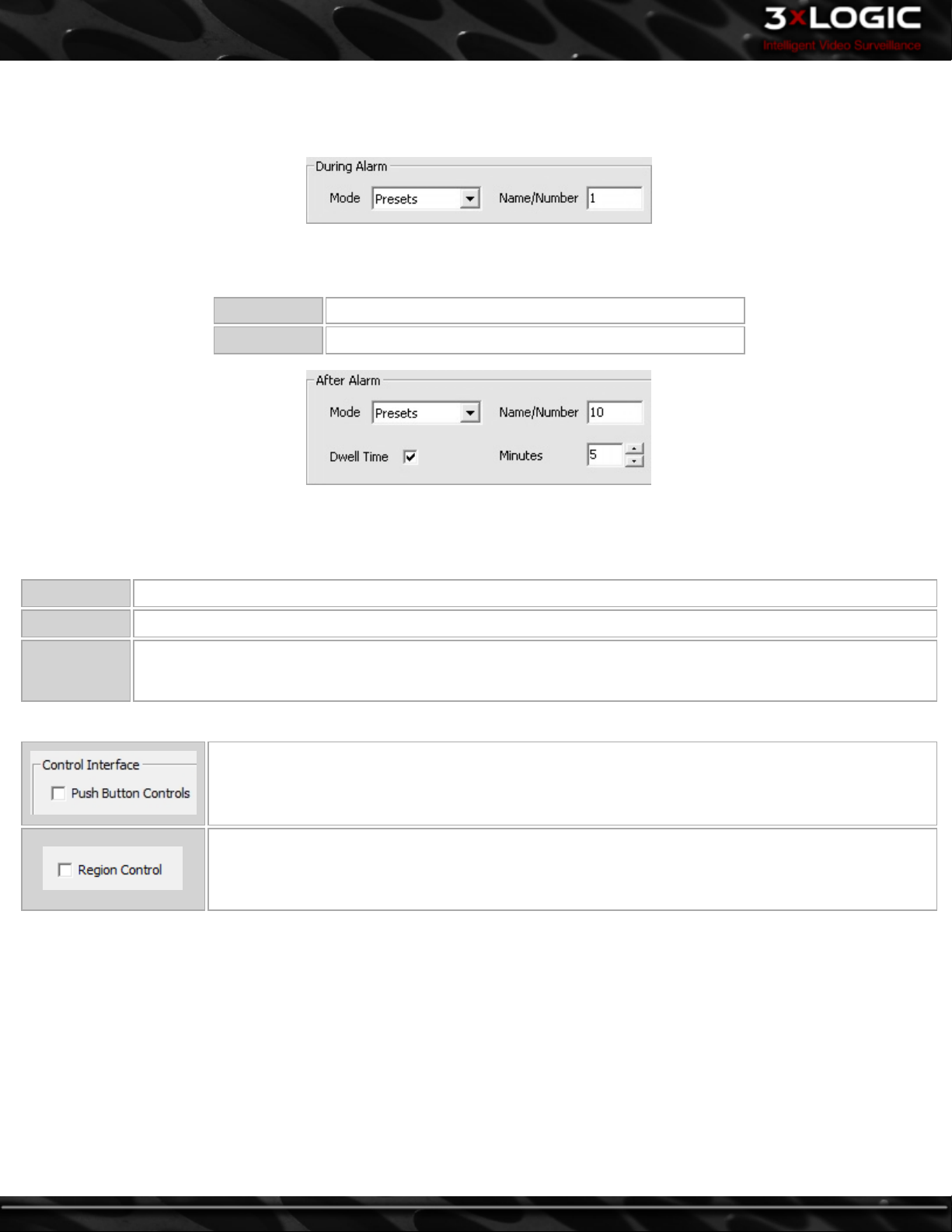
Video Analytics Alarms can also be used to Trigger TPZ events. Multiple Video Analytics Alarms can be assigned to one camera. All
Video Analytics Rules configured on the Server will show in the list, click the Checkbox beside the Rule Name to enable it.
Clicking the checkbox will open the PTZ Configuration window.
During Alarm
Select what action to apply during the DIO Alarm.
Mode Select Patterns, Presets or Tours from the drop-down box.
Name/Number Enter the Name or Number of the Pattern, Preset or Tour.
After Alarm
Select what action to apply after the DIO Alarm has ended. To do nothing after the alarm, select Disabled from the mode drop-
down.
Mode Select Disabled, Patterns, Presets or Tours from the drop-down box.
Name/Number Enter the Name or Number of the Pattern, Preset or Tour.
Dwell Time
The amount of time from when the DIO Alarm is triggered until the After Alarm event occurs. If Dwell Time is
not checked the After Alarm event will trigger when the DIO Alarm ends.
Control Interface
Enables the Push Button Directional controls for the camera in place of the virtual joystick.
Region Control is a setting that is only accessible on certain PTZ camera models. It is an alternative to
the traditional push button, joystick or on-screen drag method for controlling PTZ movement. Region
Control enables you to simply click on-screen to shift the cameras line-of-sight toward the region that
has been clicked.
-60-
©2014 3xLOGIC Inc. | VIGIL Server - User Guide
Page 70
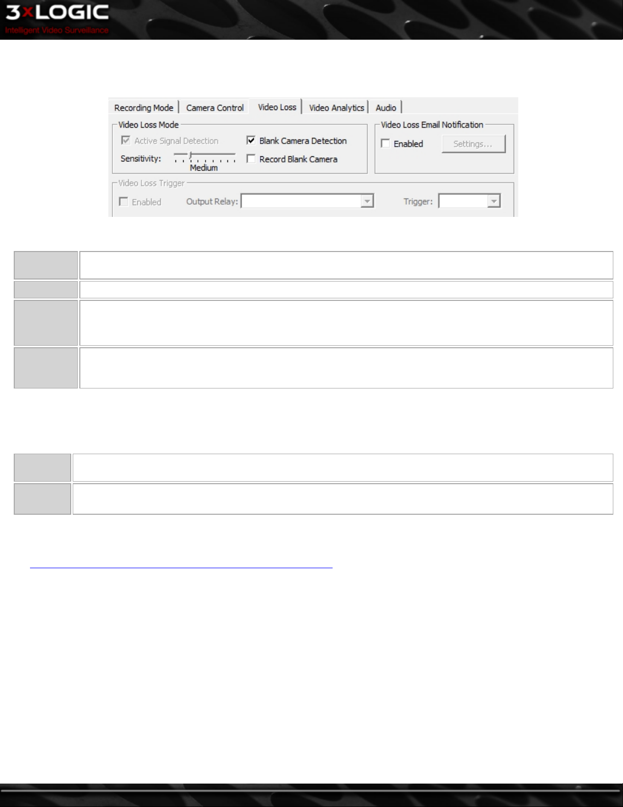
8.6 Video Loss Tab
If the video signal is lost from an enabled camera, you can specify an action to take in the Video Loss tab.
8.6.1 Video Loss Mode
Active Signal
Detection
Sensitivity Adjusts the Sensitivity of the software signal loss detection.
Blank Cam-
era Detec-
tion
Record
Blank Cam-
era
Enables hardware signal loss detection if the VIGIL Server capture card supports this feature.
When enabled, the software detects a signal loss when the live video is all black or white. This is useful if the camera is covered or blocked, and can be used in addition to or in place of hardware signal loss detection.
When enabled, the VIGIL Server continues recording the camera feed during a signal loss. The Recording Mode for
the camera must be set to Constant for this feature to work.
8.6.2 Video Loss Trigger
When enabled, Video Loss Detection triggers a DIO Relay.
Output
Relay
Trigger
Select the DIO Relay.
Select the type of trigger for the DIO Relay: Momentary, which lasts two seconds or Latched, which lasts until the
video is recovered.
8.6.3 Video Loss Email Notification
When enabled, an e-mail will be sent to the recipients configured in Email Settings... For details on how to set up e-mail recipients,
see Video Motion Alarm Advanced Settings – Email Notification Settings.
©2014 3xLOGIC Inc. | VIGIL Server - User Guide -61-
Page 71
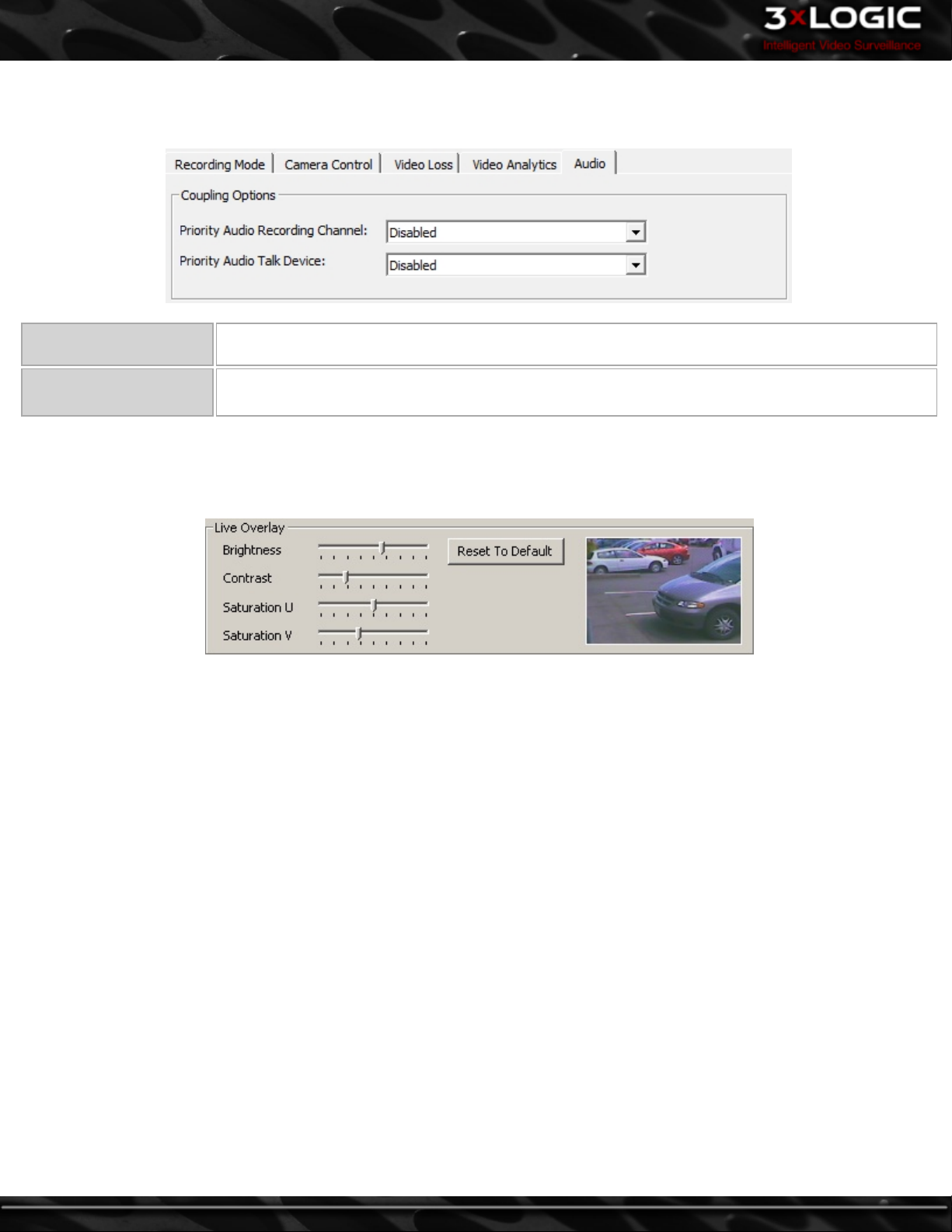
8.7 Audio Tab
The Audio tab allows you to choose a Priority Audio channel and Audio Talk device for each camera.
Priority Audio Recording
Channel
Priority Audio Talk
Device
Select the Audio Channel that will be associated with this camera. Audio Channels are configured on
the Settings - Audio Tab.
Select the Audio Talk Device that will be associated with this camera. Audio Talk devices are con-
figured on the Settings - Audio Tab.
8.8 Live Overlay Tab
VIGIL Server Systems with Live Overlay cards will enable the Live Overlay tab. The Brightness, Contrast and U/V Saturation can be
modified for the Live Overlay image.
-62-
©2014 3xLOGIC Inc. | VIGIL Server - User Guide
Page 72
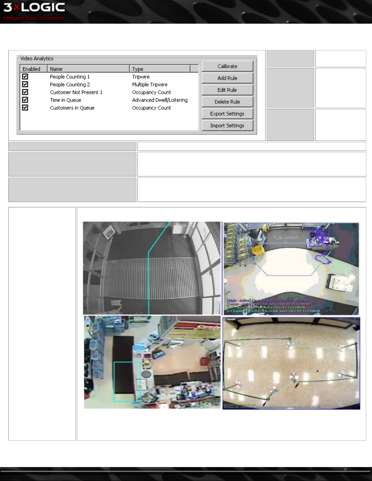
9 Settings - Video Analytics Tab
Delete Rule Deletes the selected rule.
Export Settings
Import Settings
The Video Analytics
settings of VIGIL
Server allow monitoring and tracking of
object movement
within the video. Each
individually configurable Analytics
rule type monitors
objects in a different
way. Each rule can be
set to trigger an alarm
based on criteria specified by the user.
Video analytics rules
can be configured to
use a variety of alarm
notifications such as
sending an e-mail, triggering a relay output,
or sending a notification to a VIGIL
Client station. Video
Analytics Calibration
settings and Rules can
also be exported from
one camera and
imported onto another
to save on configuration time.
Calibrate
Add Rule
Edit Rule
Export the video analytics Calibration setting sand Rules for this camera to a .dat
file. This option allows a camera to be moved to a different physical input without having to reconfigure the analytics.
Import video analytics Calibration and Rules to this Camera from a .dat file. This
option allows a camera to be moved to a different physical input without having to
reconfigure the analytics.
This example image features different video analytics such as tripwires, queue regions and live analytic
data.
Opens the Calibrate window.
Opens the Add
Rule window
where you can
choose a rule
type to add.
Opens the Rule
Settings window
for the selected
rule.
©2014 3xLOGIC Inc. | VIGIL Server - User Guide -63-
Page 73

9.1 Video Analytics Calibration
Before rules may be added and configured, the video analytics must be calibrated for each camera to ensure the proper detection
and tracking of objects. When opening the Calibration settings, you'll be presented with only three options in the left-hand menu:
General, Perspective Settings and Preview.
Select Advanced(1, above) to open up the remaining Calibration settings menu options (pictured below in the General section.)
-64-
©2014 3xLOGIC Inc. | VIGIL Server - User Guide
Page 74

9.1.1 General
To reduce CPU usage, Vigil Server reduces the resolution of the image used for Analytics calculations. It is strongly recommended
that the Max Kernel Resolution be set to CIF. Increasing the Max Kernel Resolution setting will only affect camera views with
extremely wide camera angles where objects are small enough that they are lost when the resolution is reduced to 352 x 240.
CIF 352 x 240 (recommended)
4CIF 704 x 480
Max Kernel Resolution
Megapixel 1280 x 1024
Full Resolution Full resolution recorded from the camera
Warning: Increasing the Max Kernel Resolution will result in increased CPU usage. Please monitor the CPU usage closely.
Generate
Heat Map
Checking this option enables data collection for use with the heat map functionality within the VIGIL Trends Analytics
Reporting Platform. In order for this option to function correctly, a video analytic rule must be created. See "Video Analytics Rules" on page 75
©2014 3xLOGIC Inc. | VIGIL Server - User Guide -65-
Page 75
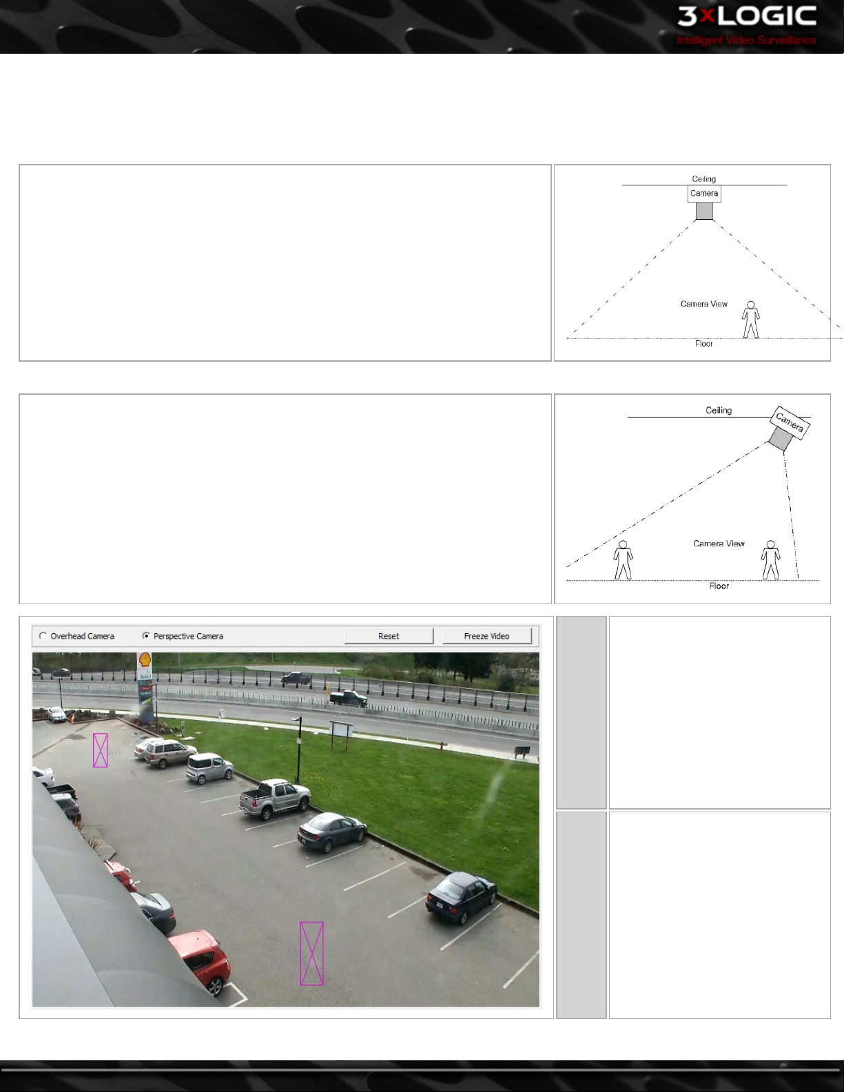
9.1.2 Perspective Settings
Select Overhead Camera if the camera view is pointed straight down. Select Perspective Camera if the camera is at an angle. Set
the person size box carefully; the accuracy of the person size box will directly affect the accuracy of analytics rules.
Overhead Camera
Overhead Camera’s are ideal for Video Analytics. Adjust the person size box to show
the average size of a person. The analytics engine uses the person size box when it is
deciding if an object is a person or a vehicle. Car size is automatically determined
relative to the person size.
Perspective Camera
The person size will increase as the person approaches the camera. Move and adjust
the first person size box to show the size and location of a person farthest from the
camera. Move and adjust the second person size box to show the size and location of
a person closest to the camera. The analytics engine uses the relative person size
boxes when it is deciding if an object is a person or a vehicle. Car size is automatically determined relative to the person size.
Reset
Freeze
Video
Click the Reset button to set all
person sizes to default. The person size boxes must be accurately
configured for the analytics rules
to function properly.
When a person is standing in the
ideal location, click the Freeze
Video button to stop the live feed
so that the person size rectangle
can be adjusted to an accurate
size. Click the Freeze Video button again to return to live video.
-66-
©2014 3xLOGIC Inc. | VIGIL Server - User Guide
Page 76

9.1.3 Object Type
Select the type of objects that will be moving through the image. The analytics engine will monitor the video for the selected object
types.
Object by
Size
Tracks only objects strictly within the configured object size. Set the minimum and maximum object size by adjusting the size of the two boxes. For perspective cameras, the minimum and maximum By Size settings will be automatically adjusted according to the perspective settings.
9.1.4 Mask Settings
Mask Settings are used to show sections of the image where objects create motion in areas that we are not interested in analyzing.
Typically, masked areas are near the edges of the image, for example trees or traffic.To create a mask region, simply draw on the
video. A semi-transparent overlay will be drawn over the video; this marks the masked region. To clear a mask, click and draw on
the masked region it.
Invert Swaps masked and clear regions.
Set All Masks the entire region.
Draw Region Click and drag to draw a rectangle which will fill in as masked area.
Clear Clears all masked regions.
Freeze Video Freezes the video, click again to return to live video.
©2014 3xLOGIC Inc. | VIGIL Server - User Guide -67-
Page 77

9.1.5 Engine Settings
Select a Predefine Mode based on the Analytics rules that will be used for this camera.
1. Tripwire Rule Optimized
2. Tripwire Rule Optimized for Fast moving Object (car, traffic, etc)
3. Occupancy Count Rule Optimized
4. Outdoor or Wide Angle shot with Less Noise
5. Predefine 4 with Less False Positive (Strict Object Identification)
6. Outdoor or Wide Angle shot with Background Noise (trees, grass, etc)
7. Predefine 6 with Less False Positive (Strict Object Identification)
8. Customized
Leave the Predefine Mode as default for Density Alarm, Appearing Object, Disappearing Object or Scene Change rules.
Customized Predefine Mode
When the Predefine Mode is set to Customized, the following settings can be adjusted. Select the most applicable Predefine Mode
from the drop-down list first and then select Customized to adjust the calibration settings manually.
The method used for object detection:
l Simple
Background
Sensitivity Adjusts the sensitivity used for analytics object detection. Higher sensitivity will detect more subtle image changes.
Track
Object
After Exists
Drop
Objects
After Miss-
ing
Object Size
Error
Range
Light
Change
l Simple with noise removal
l Advanced (Fast, for less noise environment)
l Advanced (Slow, for noisy environment with trees, grass etc)
l Advanced (Overhead Block Detection)
l Advanced (Overhead Multiple Background Block Detection)
The number of milliseconds for which the object must be detected before it is tracked as an object.Increase this
value to reduce false alarms. In a very wide field of view, this value can be safely increased. In a narrower field of
view, this value must be adjusted with caution and could possibly result in valid persons not being detected if the
value is set too high for the conditions.
The number of milliseconds for which a tracked object must be missing before it is no longer tracked.
Sets the minimum and maximum variation to the person size set in the Perspective Settings.
Allows light changes to occur within the image without triggering any false objects to appear within the image. For
example lights turning on or off.
-68-
©2014 3xLOGIC Inc. | VIGIL Server - User Guide
Page 78

Threshold
Max
Analyze
FPS
Two Pass
Object
Count
Strict size
estimation
Count by
Trace
Adjusts the maximum number of frames per second that will be used for analysis. If this value is increased, more CPU
load will be required for the analytics engine.
If objects are moving very quickly through the image in a narrow field of view then this value can be increased to
detect objects more accurately. If objects are moving very slowly through the image in a wide angle view then this
value can be decreased to reduce CPU load.
Allows more comparison with past frames to provide a more in-depth analysis using logical deductions in views with
perspective.
Puts more emphasis on the size of an object and less emphasis on its behaviour to determine if it is a valid person or
vehicle.
Objects must be travelling through the image and move valid distance
Objects must be travelling through the image at a valid speed
Average size of the object must be consistent as it moves through the image
©2014 3xLOGIC Inc. | VIGIL Server - User Guide -69-
Page 79

9.1.6 Display Options
Set what information to display on video feeds(Playback and Live)for each video Analytics Rule.
-70-
©2014 3xLOGIC Inc. | VIGIL Server - User Guide
Page 80
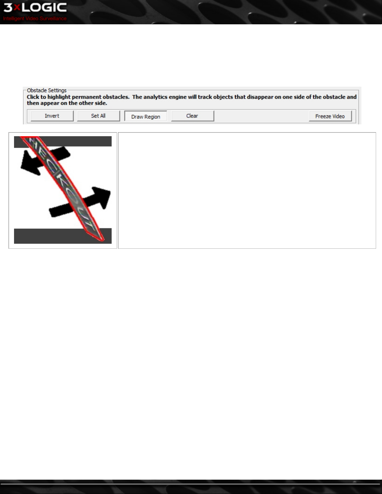
Obstacle Settings
Obstacle Settings are used to show sections of the image that are blocked by permanent, narrow objects between the area monitored
and the camera. When obstacle masks are configured, the analytics engine understands that an object will disappear behind this area
and then reappear on the other side. In some situations, light fixtures, poles, or signs could be obstacles in an image. Click to highlight permanent obstacles. The analytics engine will track objects that disappear on one side of the obstacle and then appear on the
other side.
Once the sign is masked out, analytics knows obstacles can move under the checkout sign
to the other side.
The red area shows where an obstacle mask is required.
Black arrows show the potential movement of objects through the image once the obstacle
mask is configured.
©2014 3xLOGIC Inc. | VIGIL Server - User Guide -71-
Page 81
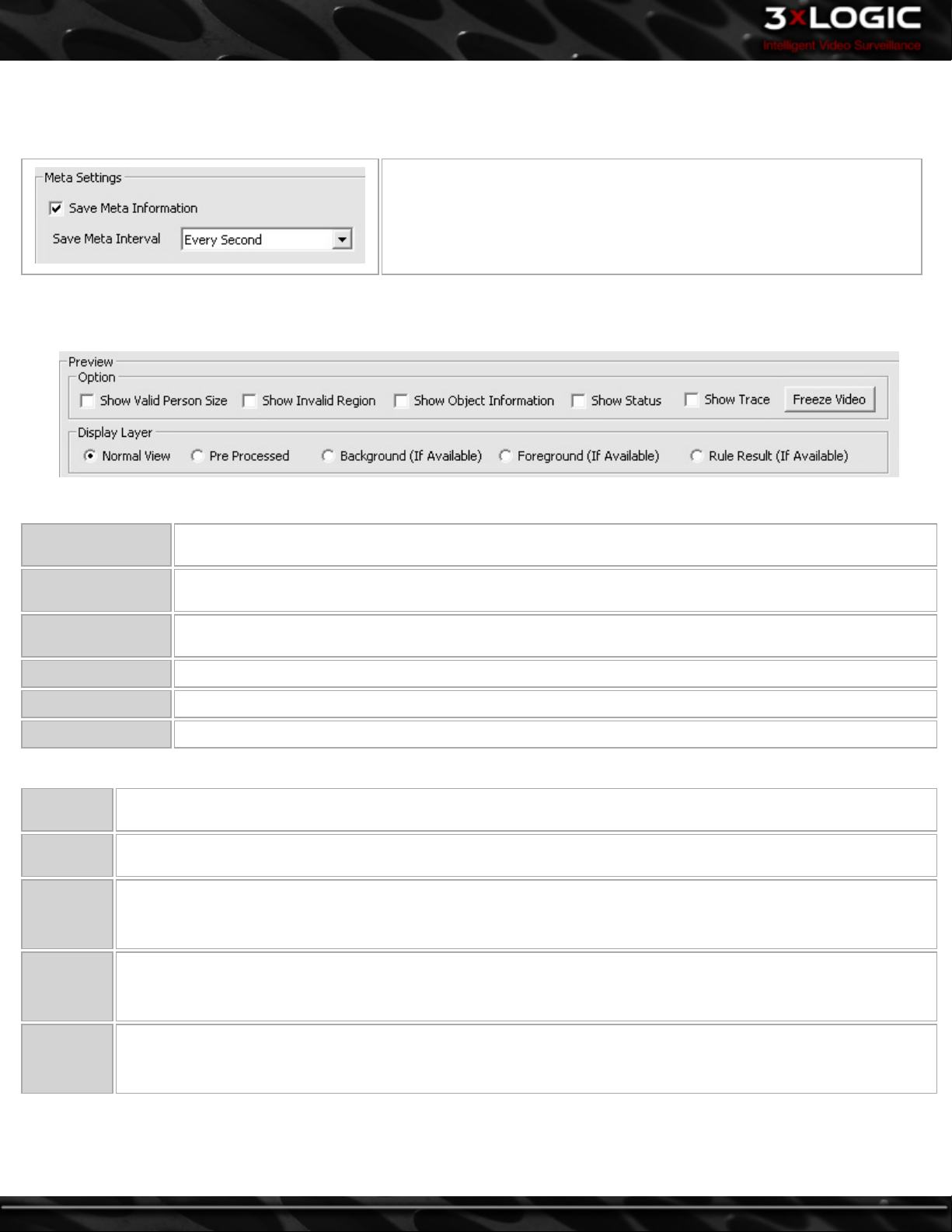
9.1.7 Meta Settings
Meta Information is analytics data that is displayed on the image. Enable Save Meta Information to view this data in other windows
such as the playback window, in exported video and in VIGIL Client.
Select how frequent the meta information will be saved.
9.1.8 Preview
Preview the calibration settings to verify they are correct.
Options
Show Valid Person
Size
Show Invalid
Region
Show Object Infor-
mation
Show Status Show information about the current settings in the bottom left corner of the image.
Show Trace Shows the tracking of a moving object through the image.
Freeze Video Freezes the Video, click again to return to live video.
When a person is in the image, shows the valid person size.
When an object that does not meet person size criteria is moving through the image, this option displays the
analyzed size of the object.
Show information about the object when it appears in the image.
Display Layer
Normal
View
Pre Proc-
essed
Background
(If Avail-
able)
Foreground
(If Avail-
able)
Rule Result
(If Avail-
able)
The view normally used in the Vigil Server live window.
The view used by the analytics engine.
The calculated background image.
Objects moving over the background image. This view is extremely useful when configuring Analytics as you will be
able to see exactly what the Analytics Engine is seeing in regards to motion.
The analytics rule result used within the analytics engine.
Example featured on the following page.
-72-
©2014 3xLOGIC Inc. | VIGIL Server - User Guide
Page 82

©2014 3xLOGIC Inc. | VIGIL Server - User Guide -73-
Page 83
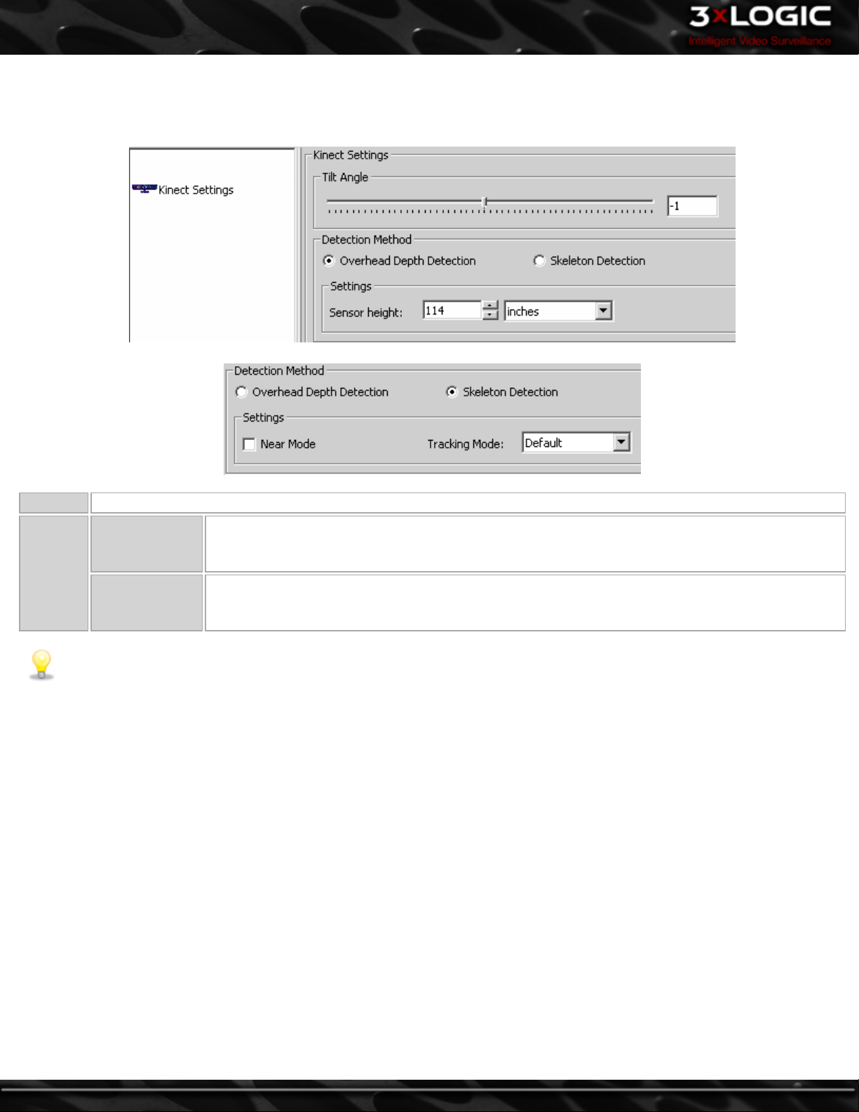
9.1.9 Kinect™ Settings
When using a Microsoft Kinect™ Device for video analytics, the calibration options are different and will only appear when a Kinect™
is installed and has been assigned to a specific channel.
Tilt Angle The Kinect™ Sensor is motorized, you can adjust the angle that the head is pointed with the slider.
Overhead Depth
Detection
Detection
Method
Skeleton Detec-
tion
Use this mode when the Kinect™ Sensor is mounted on the ceiling pointed down. The Kinect™ can
only operate between a certain height range (7.5 feet to 16.3 feet from the floor). Setting the
height of the Kinect™ allows the engine to estimate a person's physical dimensions.
Use this mode to utilize the Kinect™ sensors ability to detect a person via extrapolating their
skeleton. Near mode will allow the Kinect™ sensor to detect as close as 16 inches. Tracking mode
can be toggled between Default (Full Body) and Seated (Shoulders only) detection modes.
Note: Kinect™ settings are available for configuration through both the Calibration and the Add Rule processes.
-74-
©2014 3xLOGIC Inc. | VIGIL Server - User Guide
Page 84

9.2 Video Analytics Rules
VIGIL Server contains a powerful suite of Video Analytics Rules which provide a comprehensive range of tools to provide valuable vis-
ual and business analysis. These can be utilized to improve loss prevention and risk management, as well as track customer trends
for conversion and marketing impact.
The Video Analytics Rules listed in the below image are the most commonly encountered rules applied in the field. Configuring the
rules is only half of the equation; Auditing the analytics data to ensure it is correct as well as continual anomaly reporting to ensure
the analytics data stays accurate are also vital to the successful implementation of video analytics. For information on any rules not
listed here please consult with your sales representative.
When using a Microsoft Kinect™ device for Video Analytics, the list of rules available will be shorter. People Counting Single Trip-
wire, Number of People in Queue and Time in Queue. Click Advanced Add Rule for a comprehensive list of all video analytics rules.
©2014 3xLOGIC Inc. | VIGIL Server - User Guide -75-
Page 85
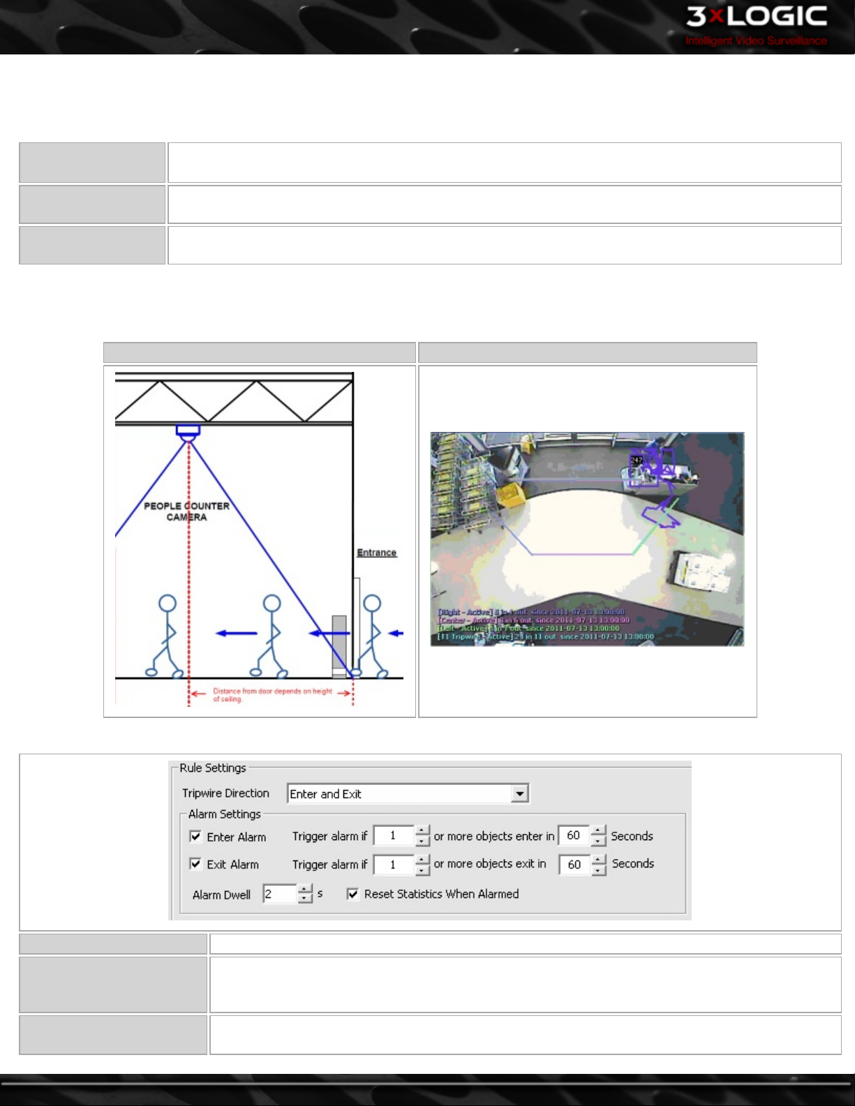
9.2.1 People Counting
Video Analytic People Counting can be used to accurately measure the unpredictable nature of pedestrian traffic in a given area.
This data can then be used for various applications such as:
Performance Metrics
Promotional and
Advertising
Staffing Optimization
People counting metrics can be used in conjunction with Point of Sale data to generate store performance
metrics such as Conversion Ratios.
Assess the effectiveness of advertising campaigns versus the corresponding increases or decreases in pedestrian traffic.
Evaluate staffing needs based on customer traffic to best optimize employee costs while still maintaining
targeted customer service levels.
Camera Placement
People counting requires a dedicated overhead-view camera mounted above the entryway to be monitored. Distance from the
entry is dependent on the height of the ceiling with the goal being a wide field of view.
Camera Positioning Guide Camera Field of View
Rule Settings Tab
Tripwire Direction Choose to monitor objects entering only, exiting only, or entering and exiting.
-76-
Enter Alarm
Exit Alarm
The Enter Alarm is triggered based on the number of people entering during a period of time.
Check the Enter Alarm checkbox to enable the alarm and then select number of people and period
of time in seconds using the arrow select tools.
The Exit Alarm is triggered based on the number of people exiting during a period of time. Check
the Exit Alarm checkbox to enable the alarm and then select number of people and period of time
©2014 3xLOGIC Inc. | VIGIL Server - User Guide
Page 86
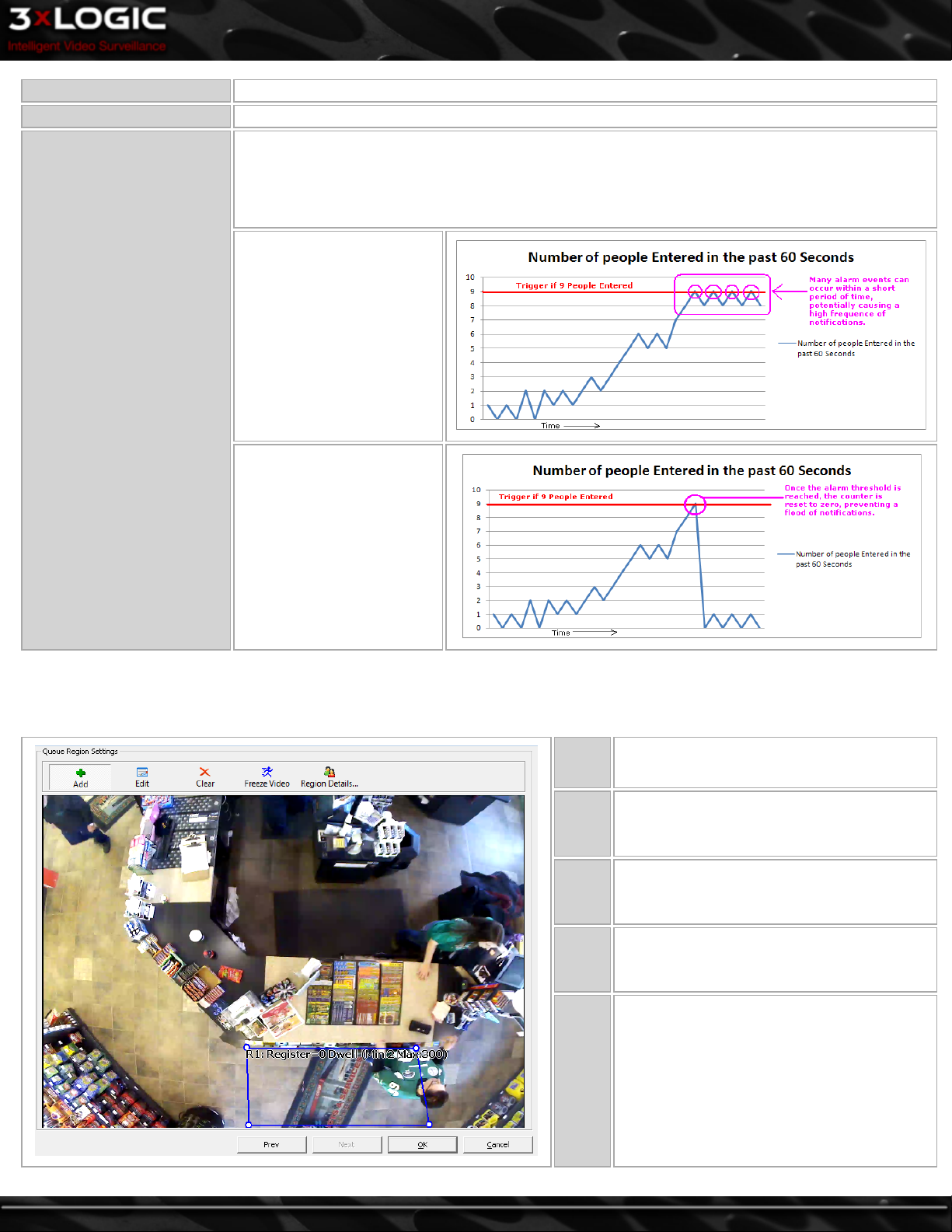
in seconds using the arrow select tools.
Alarm Dwell The number of seconds of video recorded in alarm mode once the alarm is triggered.
Enable this option to reset the statistics to zero once the alarm is triggered.
Due to the nature of the data gathered, disabling the Reset Statistics When Alarmed feature can
cause a flood of notifications when the threshold is reached.
Reset Statistics When
Alarmed-Disabled
Reset Statistics when
Alarmed
Reset Statistics When
Alarmed- Enabled
Queue Region Settings Tab
Queue Regions work in combination with a Tripwire to track how long people spend in a region before exiting that region in a specific direction.
Add
Edit
Clear
Freeze
Video
Region
Details
Click the Add button and then click to draw
the Queue Region.
Click the Edit button and then click and drag
the points of the Queue Region.
Click Clear to remove all Queue Regions
from the image.
Click the Freeze Video button to pause the
live video. Click the button again to display
live video.
Click to open the Region Details window to
assign the following settings:
l Assign a specific POS/ATM Register to
each Queue Region.
l Assign the Dwell time to set a mini-
mum time a person must spend in the
Queue Region to be counted when
they exit the Region.
©2014 3xLOGIC Inc. | VIGIL Server - User Guide -77-
Page 87

People Counting Single Tripwire
The People Counting Single Tripwire Rule counts the number of people entering and/or
exiting an area based on a tripwire line drawn across the camera's field of view. A single tripwire allows for accurate counting of pedestrian traffic entering a given area.
This rule's strength is that it only requires the analytics engine to monitor a person crossing one tripwire, reducing possible points of failure. This rule is ideal for areas where
all of the pedestrian traffic is meant to be counted.
General Tab
In this example, any traffic travelling
through this area is considered to be
entering or exiting the store.
Name
Display
Option
Database
Insert
Frequency
Description Enter a description for this Rule.
Allow Data
from...
Database
Update Set-
tings
-78-
The rule name is used to easily identify the rule in the settings, live and alarms windows. When building Analytics on
an Enterprise level, consider Rule Naming conventions to simplify searching and reporting on the data.
Select when the rule should be displayed in the live viewer. Show Rule will always display the rule, Not Show Rule
will never display the rule, Show Rule When Alarmed will only show the rule while the alarm is triggered.
The number of seconds between database entries. When a database insert is performed the on-screen count restarts.
Check this box to allow data from this rule to sync to a central database. If this box is not checked, this rule will not
sync to a central database. This allows for rules that will be used in centralized reporting to sync to a central location, while rules that are not needed for centralized reporting can stay local to the VIGIL Server and not use bandwidth / resources on the central system.
Contained at the bottom of the General tab, Database Update Settings contains a few features regarding the
method in which analytical data is written to the database. Select Write Rule Result and Write Queue Region Result
to write data to your local database. Check Allow Data from this rule to sync to central database.
©2014 3xLOGIC Inc. | VIGIL Server - User Guide
Page 88

*If selected, you will be prompted to remove all previous Rule Result(or Queue Region Result)data from the central
database to keep all stored rule data in line with your specification. Select Yes or No based on preference.
Wire Settings Tab
Click on the image to draw the tripwire threshold where objects will be counted. There must be enough space on either side of the
tripwire to detect object movement and identify the object type.
Alert Settings Tab
Add
Edit
Clear
Flip
Freeze
Video
Opens the Video Analytics Alert Settings window that allows you to
schedule the alarm recording period and configure alerts. The Video
Analytics Alert Settings window is the same as the Video Motion Alarm
Advanced Settings Window. See the section on See "Recording Mode
Tab" on page 53 under the Recording Settings Tab for configuration
information.
Click the Add button and then click to draw the trip-
wire.
Click the Edit button and then click and drag the
points of the tripwire.
Click Clear to remove all tripwire settings from the
image.
Flips the direction of the tripwire, so that Enter and
Exit are switched. Exit should be displayed on the side
where people have exited the area. Enter should be displayed on the side where people have entered the
area.
Click the Freeze Video button to pause the live video.
Click the button again to display live video.
©2014 3xLOGIC Inc. | VIGIL Server - User Guide -79-
Page 89
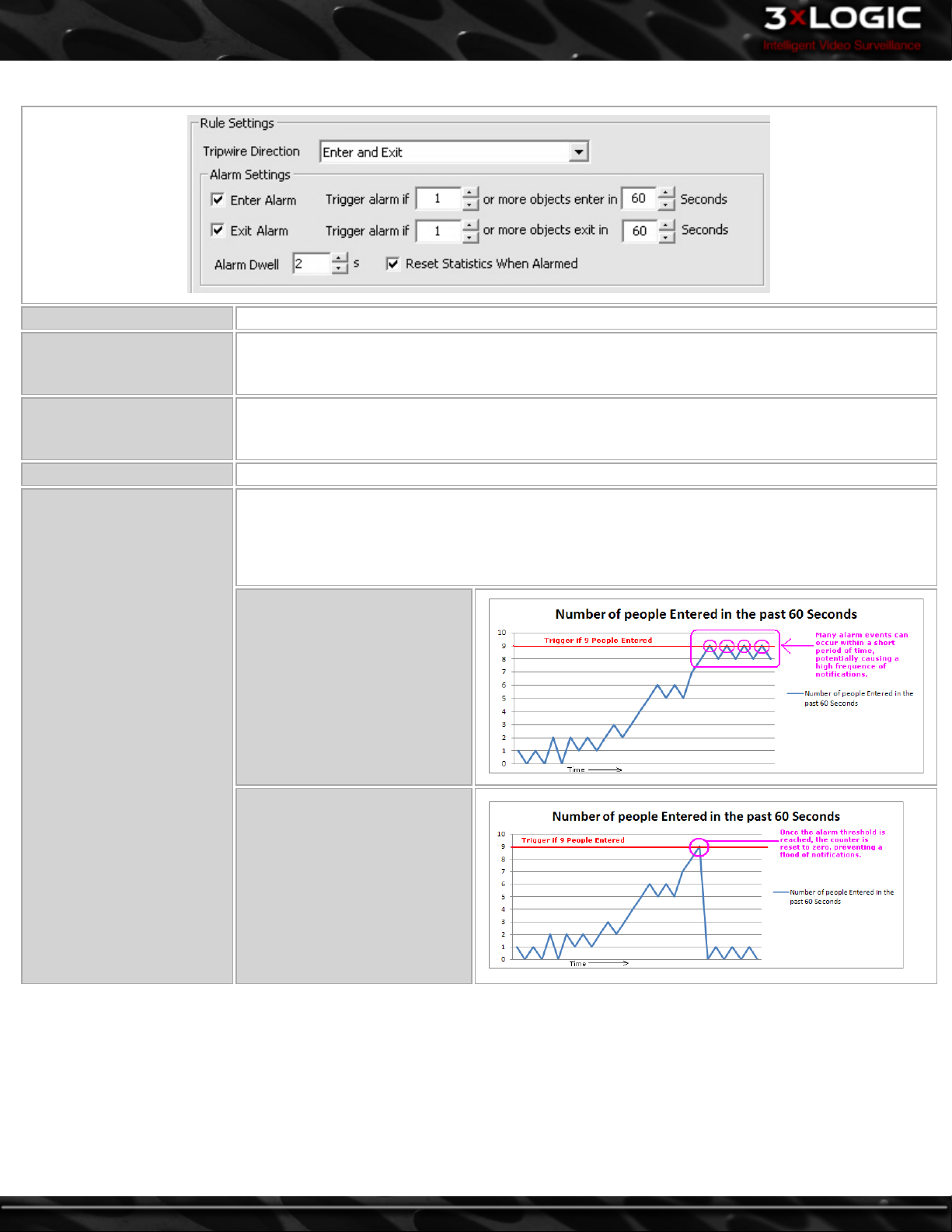
Rule Settings Tab
Tripwire Direction Choose to monitor objects entering only, exiting only, or entering and exiting.
The Enter Alarm is triggered based on the number of people entering during a period of time.
Enter Alarm
Exit Alarm
Alarm Dwell The number of seconds of video recorded in alarm mode once the alarm is triggered.
Check the Enter Alarm checkbox to enable the alarm and then select number of people and period
of time in seconds using the arrow select tools.
The Exit Alarm is triggered based on the number of people exiting during a period of time. Check
the Exit Alarm checkbox to enable the alarm and then select number of people and period of time
in seconds using the arrow select tools.
Enable this option to reset the statistics to zero once the alarm is triggered.
Reset Statistics when
Alarmed
Due to the nature of the data gathered, disabling the Reset Statistics When Alarmed feature can
cause a flood of notifications when the threshold is reached.
Reset Statistics When Alarmed-
Disabled
Reset Statistics When
AlarmedEnabled
-80-
©2014 3xLOGIC Inc. | VIGIL Server - User Guide
Page 90
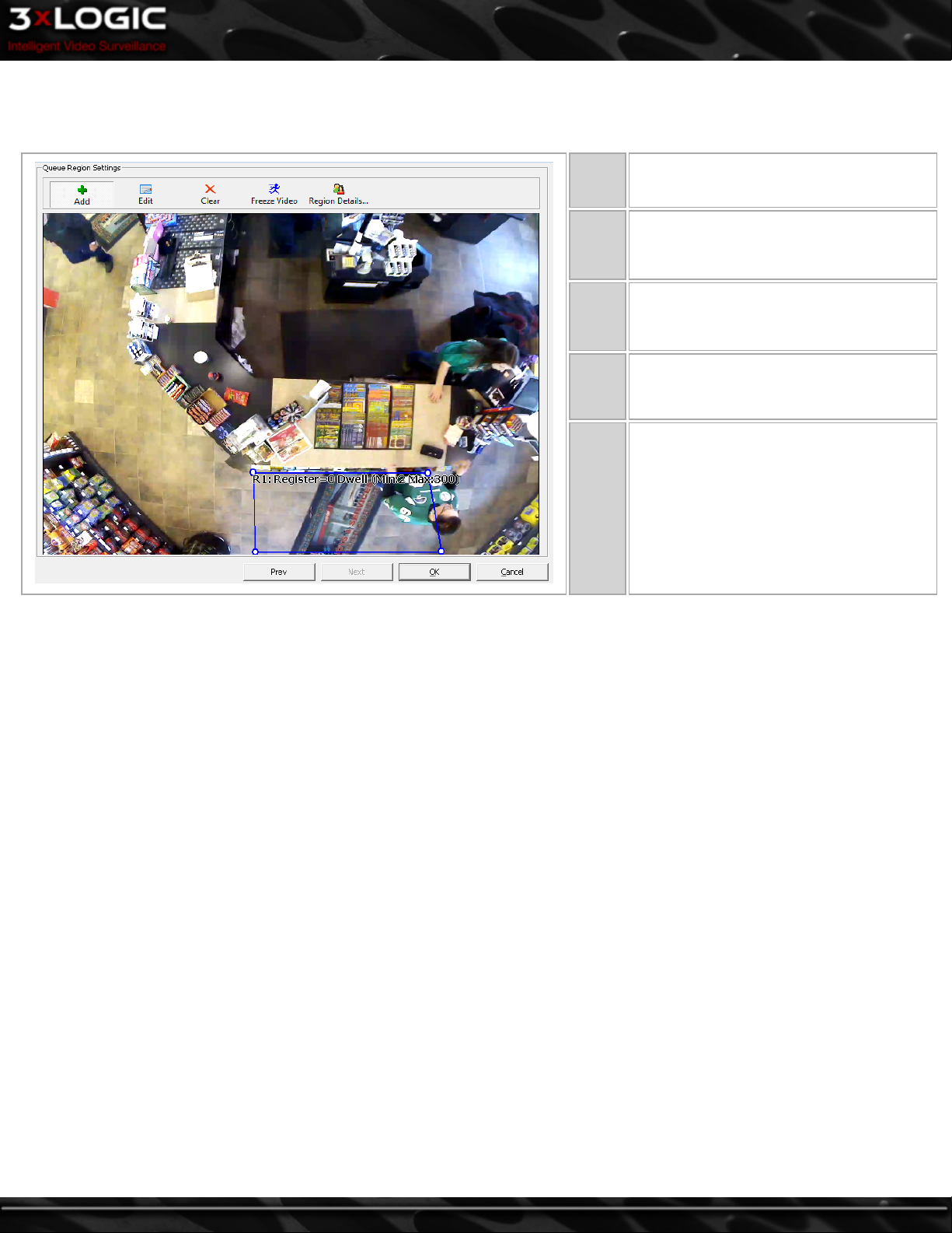
Queue Region Settings Tab
Queue Regions work in combination with a Tripwire to track how long people spend in a region before exiting that region in a specific direction.
Add
Edit
Clear
Freeze
Video
Region
Details
Click the Add button and then click to
draw the Queue Region.
Click the Edit button and then click and
drag the points of the Queue Region.
Click Clear to remove all Queue Regions
from the image.
Click the Freeze Video button to pause the
live video. Click the button again to display live video.
Click to open the Region Details window
to assign the following settings:
l Assign a specific POS/ATM Register
to each Queue Region.
l Assign the Dwell time to set a mini-
mum time a person must spend in
the Queue Region to be counted
when they exit the Region.
©2014 3xLOGIC Inc. | VIGIL Server - User Guide -81-
Page 91
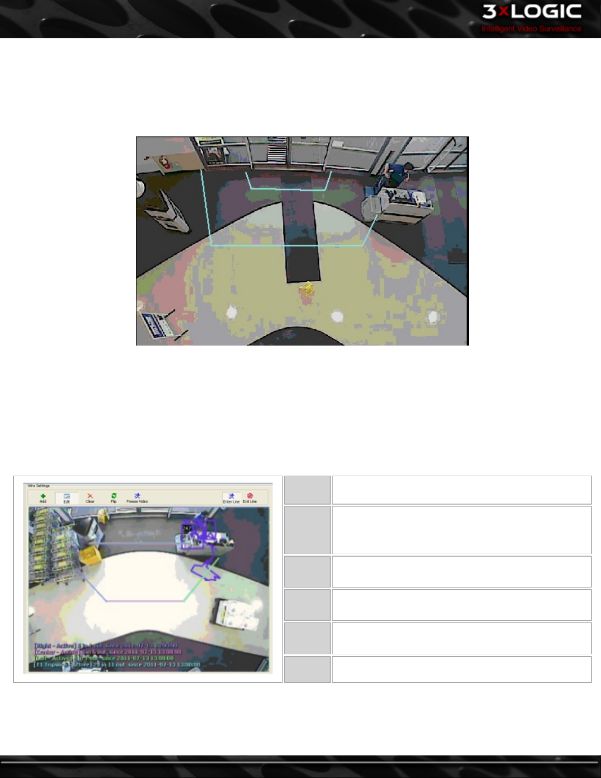
People Counting Multiple Tripwire
The People Counting Multiple Tripwire Rule counts the number of people entering and/or exiting an area based on two tripwire lines
drawn across the field of view of the camera. To be counted by this rule, the pedestrian must cross both tripwire lines. This allows
for flexibility in areas where there may be some traffic moving through the area that should not count towards the rule, however
with two tripwires for the traffic to cross, the possible points of failure are doubled. This is usually countered by the increased accuracy gained by filtering out the traffic that is not supposed to be counted by the rule.
In this example, the employee at the desk can move around without crossing both tripwires and creating a false positive, and traffic
entering through the door will be counted.
The People Counting Multiple Tripwire Rule configuration is the same as the People Counting Single Tripwire Rule. The only dif-
ference is the Wire Settings Tab.
Wire Settings Tab
Click on the image to draw the first tripwire threshold where objects will be counted. Select Exit Line and then click on the image to
draw the second tripwire threshold where objects will be counted. There must be enough space on either side of the tripwire to
detect object movement and identify the object type.
Add Click the Add button and then click to draw the tripwire.
Enter
Line /
Exit Line
Edit
Clear
Flip
Select Enter Line and click on the image to draw the first
tripwire then select Exit Line and click on the image to
draw the second tripwire.
Click the Edit button and then click and drag the points
of the tripwire.
Click Clear to remove all tripwire settings from the
image.
Flips the direction of the tripwires, so that Enter and Exit
are switched.
-82-
Freeze
Video
Click the Freeze Video button to pause the live video.
Click the button again to display live video.
©2014 3xLOGIC Inc. | VIGIL Server - User Guide
Page 92

9.2.2 Transaction with No Customer Present
No Customer Present monitoring works in conjunction with Point of Sale data coming into the VIGIL Server to determine if there is a
customer present at the register when certain transaction types are processed. This type of Analytic takes advantage of the Auto-
mated Exception capabilities of V-POS in combination with an occupancy count rule configured on the VIGIL Server.
No Customer Present analytics requires
a dedicated overhead view camera
mounted above the POS Registers with a
field of view that encompasses both the
registers and the area in front of the register.
In this example shot(pictured right,) the
rule is configured to encompass the area
a customer would stand in.
Customer Not Present Rule
General Tab
The rule name is used to easily identify the alarm in the settings, live and alarms
Name
windows. When building Analytics on an Enterprise level, consider Rule Naming conventions to simplify searching and reporting on the data.
©2014 3xLOGIC Inc. | VIGIL Server - User Guide -83-
Page 93

Display Option
Database Update Settings
Description Enter a description for this rule.
Region Settings Tab
Select when the rule should be displayed in the live viewer. Show Rule will always display the rule, Not Show Rule will never display the rule, Show Rule When Alarmed
will only show the rule while the alarm is triggered.
Check Write Rule Result and set a frequency to write rule results to a local database
in set intervals.
Check Allow Data... to allow data from this rule to sync to a central database. If this
box is not checked, this rule will not sync to a central database. This allows for rules
that will be used in centralized reporting to sync to a central location, while rules
that are not needed for centralized reporting can stay local to the VIGIL Server and
not use bandwidth / resources on the central system.
Click the Add button and then
Add
click to draw the corners of the
region. Click on the original
point to complete the region.
Alert Settings Tab
Click the Edit button and then
Edit
Clear
Freeze
Video
Opens the Video Analytics Alert Settings window that allows you to sched-
ule the alarm recording period and configure alerts. The Video Analytics
Alert Settings window is the same as the Video Motion Alarm Advanced
Settings window. See the section on See "Recording Mode Tab" on page 53
under the Recording Settings Tab for configuration information.
click and drag the corners of the
region.
Click Clear to remove all boundaries from the image.
Click the Freeze Video button to
pause the live video. Click the
button again to display live
video.
-84-
©2014 3xLOGIC Inc. | VIGIL Server - User Guide
Page 94
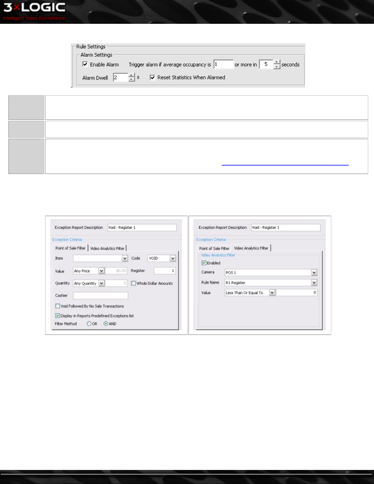
Rule Settings Tab
Enable
Alarm
Alarm
Dwell
Reset Sta-
tistics
when
Alarmed
The Enter Alarm is triggered based on the number of people entering during a period of time. Check the Enter Alarm
checkbox to enable the alarm and then select number of people and period of time in seconds using the arrow select
tools.
The number of seconds of video recorded in alarm mode once the alarm is triggered.
Enable this option to reset the statistics to zero once the alarm is triggered.
Due to the nature of the data gathered, disabling the Reset Statistics When Alarmed feature can cause a flood of
notifications when the threshold is reached. Please refer to the See "Reset Statistics when Alarmed" on page 80 sec-
tion for a graph visualizing the potential influx of notifications.
V-POS Exceptions
V-POS runs on the VIGIL Server and can be configured to monitor the POS data being captured by the VIGIL Server for pre-configured
Exception Events. These can be configured to look for specific transaction types based on a number of criteria including Video Analytics rules.
In the above Exception example, the Exception is set to monitor for VOID transactions on Register number 1 in combination with the
Occupancy Video Analytic for Register 1 having no people in the region, as represented by the Less Than or Equal to Zero. For more
Information on configuring V-POS, please consult the VIGIL Server/VIGIL Client user's guides.
©2014 3xLOGIC Inc. | VIGIL Server - User Guide -85-
Page 95

9.2.3 Queue Analytics
Queue Analytics can be used to improve customer service by monitoring metrics such as length of customer wait lines at registers or
service counters, or length of time a customer spends in the queue before getting service. Alerts can be triggered when lines reach a
set length or reports can be used to better understand customer activity for more accurate staffing levels and resource allocation.
Camera Placement
Queue Analytics requires a dedicated overhead view camera
mounted over the centre of the queue region with a field of view
wide enough to encompass the entire queue area.
Example of camera placement directly over the centre of the
Queue region is pictured-right.
Time in Queue Rule
The Time in Queue rule tracks how long a customer spends within a defined region in the cameras field of view. The time will be
tracked from the moment the customer enters the region until they exit the region in any direction. Alarms can be configured to go
off if a person remains in the region for more than a preset time. This works well for regions with a defined queue area.
General Tab
The rule name is used to easily identify the rule in the settings,
Name
Display Option
live and alarms windows. When creating Analytics on an enterprise level, consider Rule Naming conventions to simplify searching and reporting on the data.
Select when the rule should be displayed in the live viewer. Show
Rule will always display the rule, Not Show Rule will never dis-
play the rule, Show Rule When Alarmed will only show the rule
while the alarm is triggered.
-86-
Description Enter a description for this Rule.
©2014 3xLOGIC Inc. | VIGIL Server - User Guide
Page 96
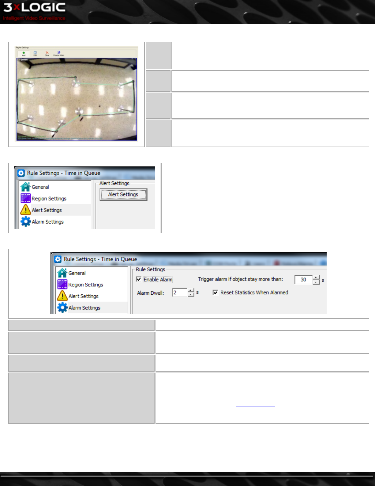
Region Settings Tab
Alert Settings Tab
Add
Edit
Clear Click Clear to remove all boundaries from the image.
Freeze
Video
Click the Add button and then click to draw the corners of the region.
Click on the original point to complete the region.
Click the Edit button and then click and drag the corners of the
region.
Click the Freeze Video button to pause the live video. Click the button
again to display live video.
Opens the Video Analytics Alert Settings window that allows you to sched-
ule the alarm recording period and configure alerts. The Video Analytics
Alert Settings window is the same as the Video Motion Alarm Advanced
Settings window. See the section on See "Recording Mode Tab" on page 53
under the Recording Settings Tab for configuration information.
Alarm Settings Tab
Enable Alarm Check to enable the alarm.
Trigger alarm if object stay more than
Alarm Dwell
Reset Statistics when Alarmed
Set the amount of time an object must be within the specified area before
an alarm is triggered.
The number of seconds of video recorded in alarm mode once the alarm is
triggered.
Enable this option to reset the statistics to zero once the alarm is triggered.
Due to the nature of the data gathered, disabling the Reset Statistics When
Alarmed feature can cause a flood of notifications when the threshold is
reached. Please refer to theTripwire Rule See "Time in Queue Rule" on page
86See "Time in Queue Rule" on page 86 section for a graph visualizing the
potential flood of notifications.
©2014 3xLOGIC Inc. | VIGIL Server - User Guide -87-
Page 97
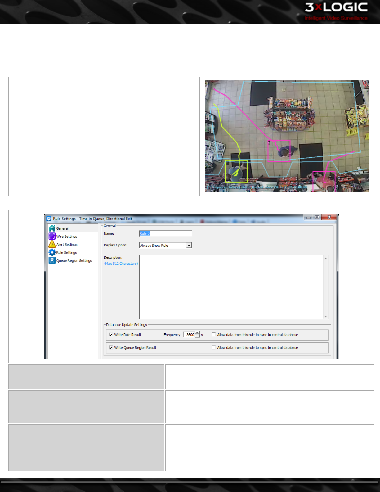
Time in Queue, Directional Exit Rule
The Time in Queue, Directional Exit Rule tracks how long a customer spends within a defined region in the cameras field of view as
long as they exit the region in a specific direction. The time will be tracked from the moment the customer enters the region until
they exit the region if they cross a defined Tripwire when exiting. This works well for application such as tracking how long a customer spends in line before getting to a cashier.
In this example shot, only customers that exit the defined region
and cross the tripwire in front of the cashiers at the bottom of the
image will be counted. This eliminates false information being
generated by people passing through the region but not waiting in
line.
General Tab
-88-
Name
Display Option
Database Insert Frequency
The rule name is used to easily identify the rule in the settings, live and
alarms windows. On an enterprise level, consider Rule Naming conventions to simplify searching and reporting on the data.
Select when the rule should be displayed in the live viewer. Show Rule
will always display the rule, Not Show Rule will never display the rule,
Show Rule When Alarmed will only show the rule while the alarm is triggered.
Check Write Rule Result and select a frequency to assign the number of
seconds between database entries. When a database insert is performed
the on-screen count restarts.
Check Write Queue Region Result to write specific region data to the
©2014 3xLOGIC Inc. | VIGIL Server - User Guide
Page 98
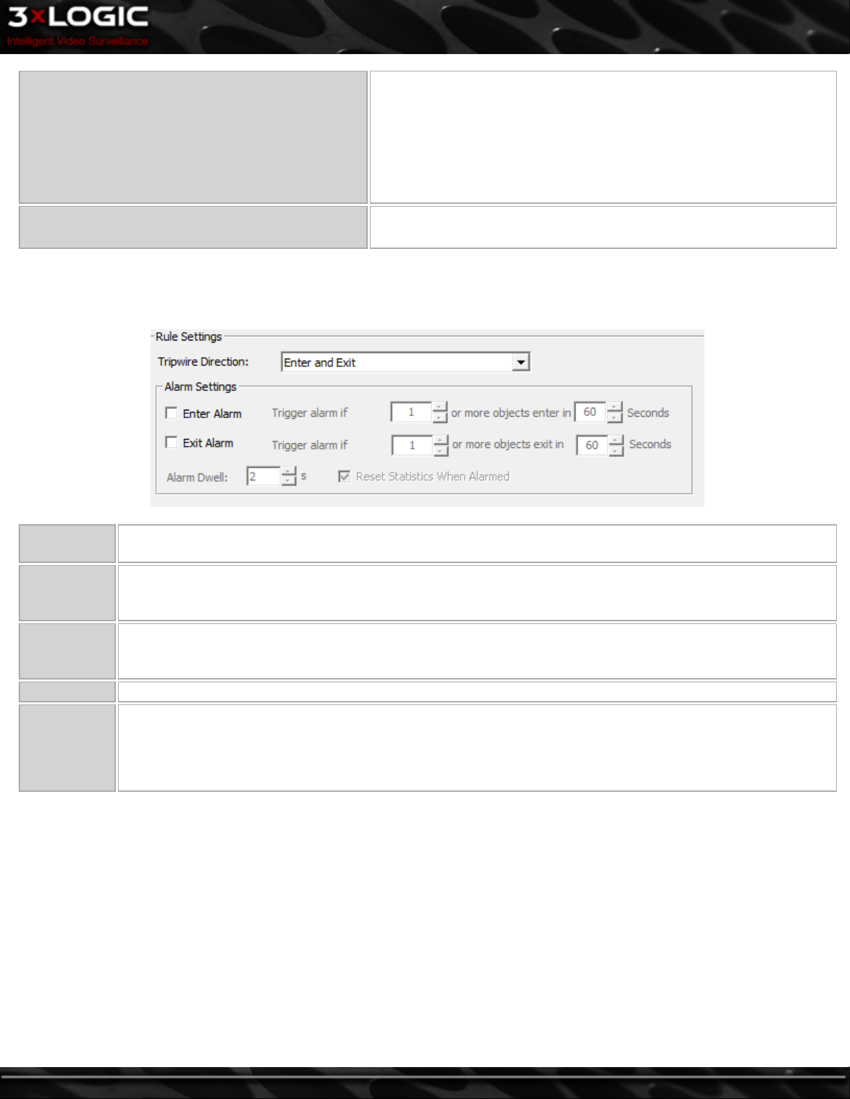
local database.
Check Allow data from... to allow data from this rule to sync to a central
database. If this box is not checked, this rule will not sync to a central
database. This allows for rules that will be used in centralized reporting
to sync to a central location, while rules that are not needed for centralized reporting can stay local to the VIGIL Server and not use bandwidth / resources on the central system.
Description Enter a description for this Rule.
Rule Settings Tab
For this rule it is recommended to set the Tripwire Direction to Exit so that the results of the rule in the database make sense as, Exiting the Queue Region.
Tripwire
Direction
Enter Alarm
Exit Alarm
Alarm Dwell The number of seconds of video recorded in alarm mode once the alarm is triggered.
Reset Sta-
tistics when
Alarmed
Choose to monitor objects entering only, exiting only, or entering and exiting.
The Enter Alarm is triggered based on the number of people entering during a period of time. Check the Enter
Alarm checkbox to enable the alarm and then select number of people and period of time in seconds using the
arrow select tools.
The Exit Alarm is triggered based on the number of people exiting during a period of time. Check the Exit Alarm
checkbox to enable the alarm and then select number of people and period of time in seconds using the arrow
select tools.
Enable this option to reset the statistics to zero once the alarm is triggered.
Due to the nature of the data gathered, disabling the Reset Statistics When Alarmed feature can cause a flood of
notifications when the threshold is reached.
©2014 3xLOGIC Inc. | VIGIL Server - User Guide -89-
Page 99

Queue Region Settings Tab
Queue Regions work in combination with a Tripwire to track how long people spend in a region before exiting that region in a specific direction.
Add
Edit
Clear
Freeze
Video
Region
Details
Click the Add button and then click to draw
the Queue Region.
Click the Edit button and then click and drag
the points of the Queue Region.
Click Clear to remove all Queue Regions from
the image.
Click the Freeze Video button to pause the
live video. Click the button again to display
live video.
Click to open the Region Details window to
assign the following settings:
l Assign a specific POS/ATM Register to
each Queue Region.
l Assign the Dwell Time to set a minimum
(and/or maximum) time a person must
spend in the Queue Region to be
counted when they exit the Region.
-90-
©2014 3xLOGIC Inc. | VIGIL Server - User Guide
Page 100
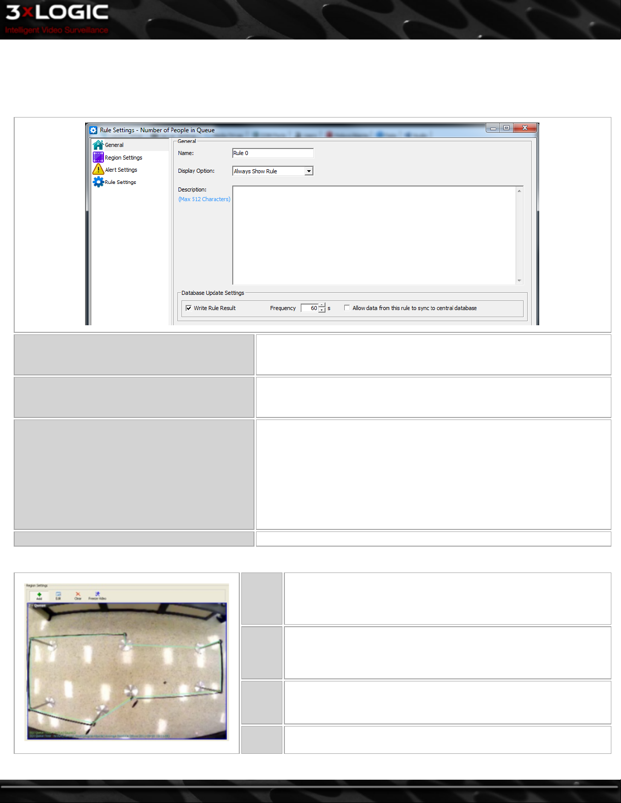
Number of People in Queue Rule Settings
The Number of People in Queue Rule tracks how many customers are currently within a defined region in the cameras field of view.
This rule can be configured to send out an alert when the number of customers currently in the queue exceeds a set amount.
General Tab
The rule name is used to easily identify the alarm in the settings, live and
Name
Display Option
alarms windows. When creating analytics on an enterprise level, consider
Rule Naming conventions to simplify searching and reporting on the data.
Select when the rule should be displayed in the live viewer. Show Rule will
always display the rule, Not Show Rule will never display the rule, Show
Rule When Alarmed will only show the rule while the alarm is triggered.
Check Write Rule Result and set a frequency to write rule results to a local
database in set intervals.
Database Insert Frequency
Region Settings Tab
Check Allow data... to allow data from this rule to sync to a central
database. If this box is not checked, this rule will not sync to a central
database. This allows for rules that will be used in centralized reporting to
sync to a central location, while rules that are not needed for centralized
reporting can stay local to the VIGIL Server and not use bandwidth /
resources on the central system.
Description Enter a description for this Rule.
Add
Edit
Clear Click Clear to remove all boundaries from the image.
Freeze
Video
Click the Add button and then click to draw the corners of the region.
Click on the original point to complete the region.
Click the Edit button and then click and drag the corners of the
region.
Click the Freeze Video button to pause the live video. Click the button
again to display live video.
©2014 3xLOGIC Inc. | VIGIL Server - User Guide -91-
 Loading...