

Page 1

INSTALLATION AND OPERATING
MODELS:
HWS050
HWS100
INSTRUCTIONS
HWS SERIES HOT WATER SOFTENERS
Installer, please leave with homeowner.
3M is a trademark of 3M Company.
© 2012 3M Company. All rights reserved.
IN303 0912B
Please recycle. Printed in U.S.A.
3M Purification Inc.
400 Research Parkway
Meriden, CT 06450, USA
Toll Free: 866.990.9785
Worldwide: 203.237.5541
Fax: 203.238.8701
www.3Mfoodservice.com
www.3Mpurification.com
Page 2
SAFETY INFORMATION
Limited Warranty
Read, understand, and follow all safety information contained in these instructions prior to installation and use of the 3M
HWS hot water softeners. Retain these instructions for future reference.
Intended use:
The HWS hot water softeners are intended for use in softening hot water in Foodservice installations. The system is intended
for indoor installations near the entry point of a foodservice water line, and must be installed by qualifi ed professional installers
according to these installation instructions.
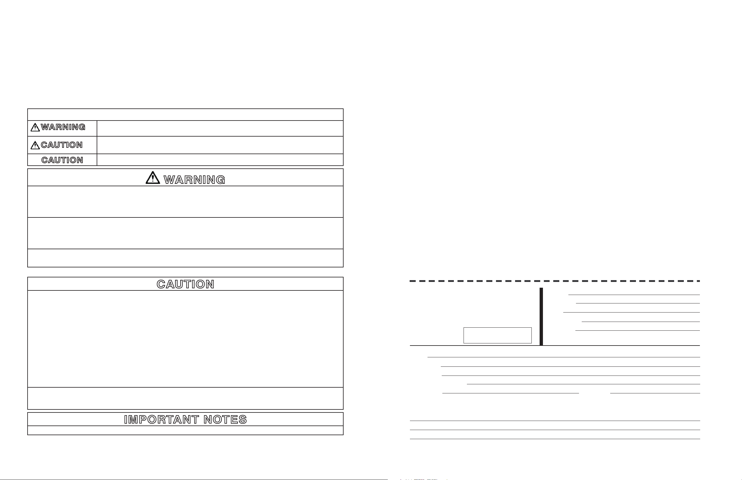
EXPLANATION OF SIGNAL WORD CONSEQUENCES
WARNING
CAUTION
CAUTION
Indicates a potentially hazardous situation, which, if not avoided, could result in death or serious
injury and/or property damage.
Indicates a potentially hazardous situation which, if not avoided, may result in minor or moderate
injury and/or property damage.
Indicates a potentially hazardous situation, which, if not avoided, may result in property damage.
WARNING
To reduce the risk associated with ingestion of contaminants due to use with water that is microbiologically unsafe or of
unknown quality:
• Do not use with water that is microbiologically unsafe or of unknown quality without adequate disinfection before or after the
system.
To reduce the risk associated with hazardous voltage:
• If the electrical system requires use of the cold water system as an electrical safety ground, a jumper must be used to ensure
a suffi cient ground connection across the softener installation piping — refer installation to qualifi ed personnel.
• Do not use the softener if the wall-mounted power supply is damaged — contact qualifi ed service personnel for repair.
To reduce the risk associated with back strain:
• Follow safe lifting procedures.
3M Purification Inc. warrants HWS050 and HWS100 will be free from defects in material and manufacture for the following
periods from the date of purchase:
• One (1) year on the entire unit
• Five years on mineral tank only (does not include internal components)
• Five years on control valve body only (does not include internal or external components)
• Five years on salt storage container and components.*
This warranty does not cover failures resulting from abuse, misuse, alteration or damage not caused by 3M Purification Inc. or
failure to follow installation and use instructions. 3M PURIFICATION INC. MAKES NO OTHER WARRANTIES OR CONDITIONS,
EXPRESS OR IMPLIED, INCLUDING, BUT NOT LIMITED TO, ANY IMPLIED WARRANTY OR CONDITION OF MERCHANTIBILITY
OR FITNESS FOR A PARTICULAR PURPOSE OR ANY IMPLIED WARRANTY OR CONDITION ARISING OUT OF A COURSE OF
DEALING, CUTOMER OR USAGE OF TRADE. If this Product fails to satisfy this Limited Warranty during the warranty period, 3M
Purification Inc. will replace the Product or refund your Product purchase price. This warranty does do cover labor. The remedy
stated in this paragraph is the Customer’s sole remedy and 3M Purification’s exclusive obligation.
This warranty gives you specific legal rights, and you may have other rights which vary from state to state, or country to country.
For any warranty questions, please call 855.3M.WATER (855.369.2837) or mail your request to: Warranty Claims, 3M Purification
Inc., 400 Research Parkway, Meriden, CT 06450. Proof of purchase (original sales receipt) must accompany the warranty claim,
along with a complete description of the Product, model number and alleged defect.
Limitation of Liability: 3M Purification Inc. will not be liable for any loss or damage arising from this 3M Purification Inc. product,
whether direct, indirect, special, incidental, or consequential, regardless of the legal theory asserted, including warranty, contract,
negligence or strict liability. Some states and countries do not allow the exclusion or limitation of incidental or consequential
damages, so the above limitation or exclusion may not apply to you.
*water softeners only
CAUTION
To reduce the risk associated with property damage due to water leakage:
• Read and follow Use Instructions before installation and use of this system;
• Installation must comply with existing state or local plumbing codes;
• Protect from freezing. Drain system when temperatures drop below 40°F (4.4°C);
• Do not install if water pressure exceeds 100 psi (689 kPa). If the system water pressure exceeds 100 psi, the installation must
use a pressure limiting valve. Contact a licensed plumbing professional if you are uncertain how to check your water pressure;
• Do not install system where water lines could be subjected to vacuum conditions without appropriate measures for vacuum
prevention;
• When water supply is shut off, shut off fuel or electric power to water heater;
• Do not use torches or other heat sources near plastic plumbing, as damage may occur;
• Take care when using pliers or pipe wrenches to tighten plastic fi ttings, as damage may occur;
• On plastic fi ttings, use thread sealing tape only. Never use pipe sealant or pipe dope on plastic fi ttings, as damage may occur;
• Do not bend spring on fl oat assembly or damage to the vent may result;
• Do not install this system in direct sunlight or outdoors without protection from precipitation.
To reduce the risk associated with property damage due to plugged water lines:
• Pay particular attention to correct orientation of control valve. Water fl ow should match arrow on control valve
. The Inlet and
Outlet of other water treatment equipment products will vary depending on the control valve brand used.
IMPORTANT NOTES
• Failure to follow instructions may result in leakage and will void warranty.
WATER TREATMENT SYSTEM
PRODUCT REGISTRATION CARD
3M Purification Inc., 400 Research Parkway, Meriden, CT U.S.A.
PLEASE PRINT
THANK YOU
Model #
Where Purchased
Business Address
Equipment this system is used on
Model # (if known) Manufacturer
If the filter is used on more than one machine, please list below.
DATE OF
PURCHASE
Street
Mo. Yr.
Your Name
Business Name
Address
Telephone Number ( )
E-mail Address
NOTICE: Personal information collected in this card will only be used for 3M
Product Registration purposes.
Street
City State & Zip Code
edoC piZ & etatS ytiC
rerutcafunaM ledoM tnempiuqE
Page 3
TABLE OF CONTENTS
SECTION 7: MAINTENANCE
REPLENISHMENT OF SALT SUPPLY:
SECTION DESCRIPTION
1 BEFORE INSTALLATION
2 INSTALLATION
3 REGENERATION INSTRUCTIONS
(Timer Setting Instructions)
4 SERVICE INSTRUCTIONS
5 SPECIFICATIONS AND OPERATING DATA
6 PARTS
7 MAINTENANCE
SECTION 1: BEFORE INSTALLATION
Before starting the installation we suggest reading this manual all the way through for an overview, and then follow the installation steps
in the proper sequence. IMPROPER INSTALLATION could void the warranty. Installation should be completed by a qualifi ed plumber.
INSPECTING AND HANDLING THE WATER SOFTENER:
Inspect the equipment for shipping damage. If damaged, notify the transportation company and request a damage inspection.
Handle the equipment with care. Damage can result if dropped or if the brine tank is set on sharp, uneven projections on the fl oor. When
handling, do not turn the water softener unit upside down.
MAKE SURE YOUR WATER HAS BEEN THOROUGHLY TESTED:
The salt storage capacity of the brine tank is approximately 280 lbs. (127 kg). During each regeneration a specifi c amount of salt is
consumed, thus requiring its periodic replenishment (the frequency is dependent on the regeneration schedule). Always replenish salt
before the supply is exhausted to assure a continuous supply of softened water.
TYPE OF SALT TO USE:
Any type of water softener salt may be used. There are advantages and disadvantages to every type of salt. Please ask the local dealer
for his advice. The unit is designed to compensate for the disadvantages.
BRINE TANK CLEAN-OUT:
To prevent service problems the brine tank should be emptied and fl ushed out with a garden hose when dirt and other insolubles accumulate. The clean-out frequency depends on the type salt used and regeneration frequency. The clean-out should be done when the
salt level is low. Steps to follow:
1) Disconnect brine line at either end.
2) Turn brine tank upside down and discard old salt. Remove salt grid plate.
3) Rinse out with a garden hose.
4) Reconnect brine line.
5) Add enough water to brine tank to cover
year if rock salt is used; with other types of salt, approximately once every other year.
the air check in the brine well 1" before adding new salt. Perform approximately once a
PREVENTING IRON-FOULING OF MINERAL BED:
If iron is present in the water supply, the softener mineral bed will eventually become iron-fouled, resulting in reduced softening capacity and rust-stained fi xtures. Mixing one to two ounces of IRON-X Mineral Cleaner with every 80 lbs. of salt added to brine tank will
minimize these problems from occurring. IRON-X is available from the dealer.
An analysis of the water should be made prior to the selection of water conditioning equipment. The dealer will generally perform this
service, and may send a sample to the factory for analysis and recommendations. Enter the analysis below for a permanent record.
IMPORTANT NOTES
Hydrogen sulfi de (H2S) must be tested for at the well site. For accuracy, the sample must be drawn with the pump RUNNING, and the
test be completed within ONE minute after the sample is drawn.
Softeners are designed to remove hardness but can handle reasonable amounts of soluble iron if consideration is given to content when
selecting model and regeneration settings. To treat sulfur (hydrogen sulfi de), bacterial iron, precipitated iron or very high levels of soluble
iron requires special equipment in addition to a water softener. For best results, a Chem-Free Iron Reduction Filter is recommended for
use on waters containing more than 2 ppm of iron.
Analysis Of Your Water
CONTAMINANT YOUR WATER
gpg___________ssendraH
Iron (Fe) ___________ppm
Manganese (Mn) ___________ppm
___________Hp
Tannins (Humic Acid) ___________ppm
Hydrogen Sulfi de (H
Other____________________ ___________ppm
Other____________________ ___________ppm
S) ___________ppm
2
PERIODICALLY CHECK TIME OF DAY SETTING:
Power outages will cause TIME OF DAY timer setting to become incorrect. To reset, refer to appropriate HOW TO SET TIME CLOCK
REGENERATION CONTROL, Section 3.
MALFUNCTION OF UNIT:
The water softener, under normal conditions, should provide years of trouble-free service; however, since it is a mechanical device, it
can malfunction. (Refer to Section 4, SERVICE INSTRUCTIONS, if necessary).
CHANGE OF OPERATING CONDITIONS:
Should the daily water usage, or water quality change, the regeneration program settings may have to be adjusted. Consult the dealer
if any of the above occur.
1-1
7-1
Page 4

CHECK WATER PRESSURE AND PUMPING RATE:
Two water system conditions must be checked carefully to avoid unsatisfactory operation or equipment damage:
1) MINIMUM water pressure required at the softener tank inlet is 20 psi. IF PRESSURE IS OVER 100 PSI, A PRESSURE REDUCING VALVE MUST BE INSTALLED IN THE WATER SUPPLY LINE AHEAD OF THE WATER SOFTENER.
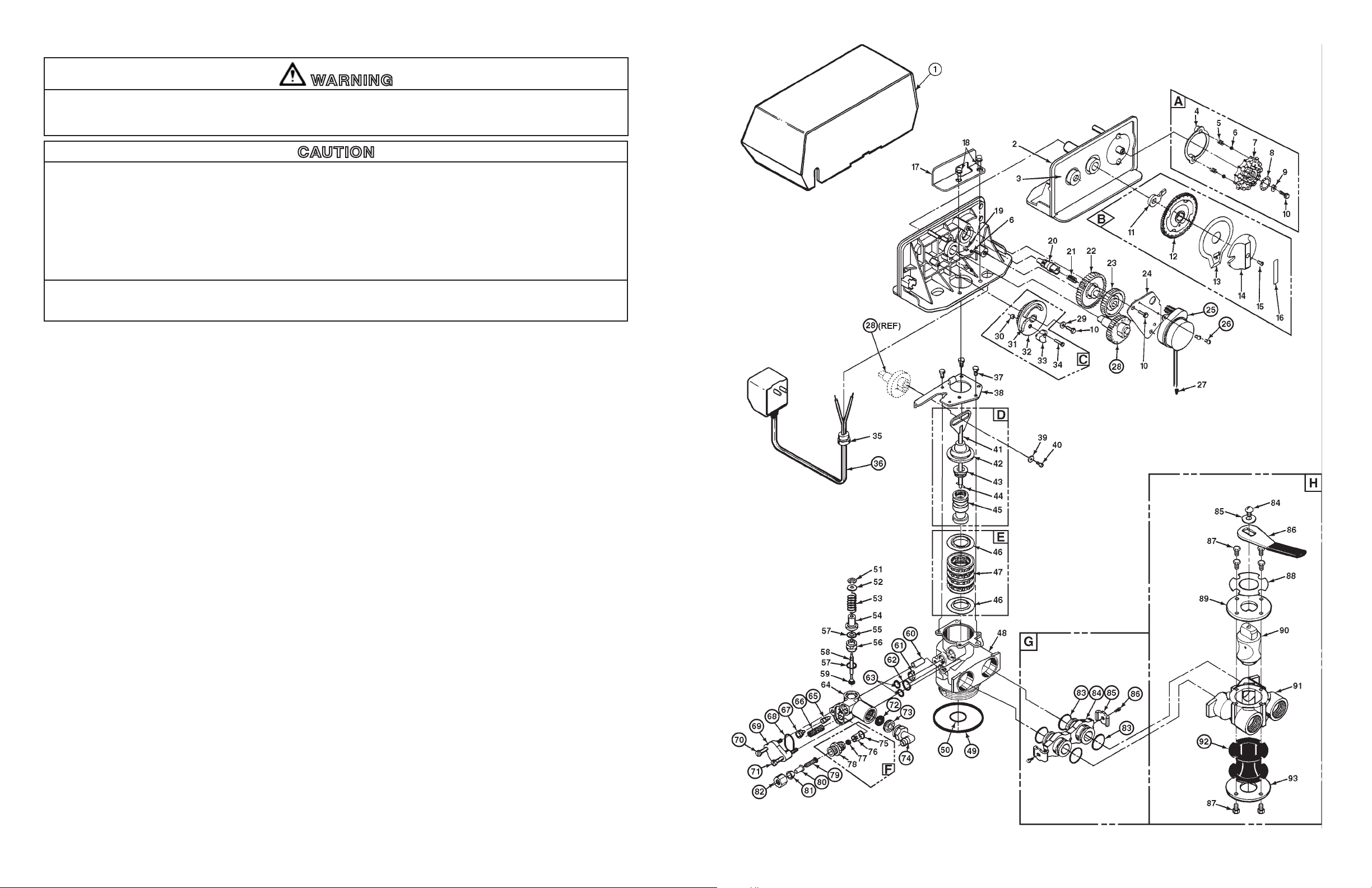
ONLY THOSE PARTS CIRCLED IN DRAWING AND/OR LISTED BELOW ARE STOCK ITEMS
ALL OTHERS ARE SPECIAL ORDER, NON-RETURNABLE
PARTS LIST - 12 DAY TIMER
CAUTION
To reduce the risk associated with property damage due to water leakage:
• Do not install if water pressure exceeds 100 psi (689 kPa). If the system water pressure exceeds 100 psi, the installation
must use a pressure limiting valve. Contact a licensed plumbing professional if you are uncertain how to check your water
pressure.
• Do not install system where water lines could be subjected to vacuum conditions without appropriate measures for vacuum
prevention.
IMPORTANT NOTE
If the source is a municipal or a community water supply and daytime water pressure is 85 psi or more, nighttime pressure may
exceed 100 psi. Call the local water department or plant operator to obtain pressure readings. If the source is a private well, the
gauge on the pressure tank will indicate the high and low system pressure. Record water pressure data below:
WATER PRESSURE
Low _______ psi High _______ psi
2) If the source of water is a private well, the pumping rate of the well pump must be suffi cient for satisfactory operation and BACKWASHING of the WATER SOFTENER. (See SPECIFICATIONS AND OPERATING DATA, Section 5).
LOCATE WATER CONDITIONING EQUIPMENT CORRECTLY:
Select the location of the water softener with care. Various conditions which contribute to proper location are as follows:
1) Locate as close as possible to water supply source.
2) Locate as close as possible to a fl oor or other adequate drain.
3) Locate in correct relationship to other water conditioning equipment (Figure 1).
4) Temperatures above 150° F (66° C) will damage the softener and void the factory warranty.
5) Do NOT install the softener in a location where freezing temperatures occur. Freezing may cause permanent damage and will also
void the factory warranty.
6) Allow suffi cient space around the unit for easy servicing.
7) Provide a non-switched 110V, 60Hz power source for the control. (Ref
erence transformer to verify proper power supply voltage.)
REF.
A
B
C
D
E
F
G
H
1
25
26
28
36
50
49
60
61
62
63
65
66
67
68
69
70
71
72
73
74
79
80
81
82
83
84
85
86
92
14381X
13010XT
60514-02
60102-031
60125-05
60022-501
10090X
60040
22602
19659
11384
13170
U321
13304
10381-01
13361
13497
12638-01
13301-01
10226-1
10227
10225-1
13303-01
13166
13387
13315
12091
13173
12338
12767
10332
10330
10329
13305
13709
13255
13314
14105
DESCRIPTIONPART NO.
Skipper Wheel Assy. (Incl. Ref. Items 4-10)
24-Hour Gear Assy. (Incl. Ref. Items 11-16)
Brine Cam Assy. Minutes of Refi ll Salt (Incl. Ref. Items 30 - 34)
Piston Kit (Incl. Ref. Items 41-45)
Seal Kit, HW (Incl. Ref. Items 46 & 47)
Brine Line Flow Control Assy., 0.50 GPM, (Incl. Ref. Items 75-78)
Adapter Coupling Assy. (Incl. 2 ea. Ref. Items 84-86 & 4 ea. Item 83)
3/4" Bypass Valve, 316SS, Hot/Cold
Valve Cover, Specify Model
Motor, 24V/60 Hz
Motor Mtg. & Ground Screw
Main Gear
Transformer, 110V/60Hz - 24V/60Hz
Distributor Tube O-Ring
Tank O-Ring
Stand-off
Air Disperser
Drain O-Ring, HW
Injector O-Ring, HW
Injector Throat - Specify Size
Injector Screen
Injector Nozzle - Specify Size
Injector Cover O-Ring
Injector Cover
Screw, Injector Mounting
Injector Mounting Screw
Drain Line Flow Control Button:
4.0 GPM
Drain Line Flow Control Retainer
Drain Line Fitting
Brine Line Screen
Brine Line Tube Insert
Brine Line Ferrule
Brine Line Fitting Nut
Adapter Coupling O-Ring
Adapter Coupling
Adapter Clip (Incl. 2 ea. Ref. Item 83)
Adapter Coupling Screw
Seal, Bypass
1-2
6-4
Page 5
FACTS TO REMEMBER WHILE PLANNING THE INSTALLATION:
WARNING
To reduce the risk associated with hazardous voltage:
• If the electrical system requires use of the cold water system as an electrical safety ground, a jumper must be used to ensure a
suffi cient ground connection across the softener installation piping — refer installation to qualifi ed personnel.
CAUTION
To reduce the risk associated with property damage due to water leakage:
• Installation must comply with existing state or local plumbing codes.
• Do not install if water pressure exceeds 100 psi (689 kPa). If the system water pressure exceeds 100 psi, the installation must
use a pressure limiting valve. Contact a licensed plumbing professional if you are uncertain how to check your water pressure.
• Do not install system where water lines could be subjected to vacuum conditions without appropriate measures for vacuum
prevention.
• Do not use torches or other heat sources near plastic plumbing, as damage may occur.
• Take care when using pliers or pipe wrenches to tighten plastic fi ttings, as damage may occur.
• On plastic fi ttings, use thread sealing tape only. Never use pipe sealant or pipe dope on plastic fi ttings, as damage may occur.
To reduce the risk associated with property damage due to plugged water lines:
• Pay particular attention to correct orientation of control valve. Water fl ow should match arrow on control valve. The Inlet and
Outlet of other water treatment equipment products will vary depending on the control valve brand used.
Remember that the fi lter INLET is
toward the water heater or other water treatment equipment device.
Before commencing the installation, it is advisable to study the existing piping system and to determine the size, number and type of
fi ttings required. Typical system schematics shown in Figure 1 will be of assistance.
attached to the pipe that supplies water (i.e. runs to the pump) and OUTLET is the line that runs
CONTROL VALVE
- 12 DAY TIMER
1-3
6-3
Page 6

SECTION 2: INSTALLATION
HOT WATER FILTER
SOFT
WATER
RAW
WELL
WATER
BRINE
MAKER
SOFTENER
Figure 1. INSTALLATION SCHEMATIC
CAUTION
To reduce the risk associated with property damage due to
water leakage:
• When water supply is shut off, shut off fuel or electric power to
water heater;
• Do not use torches or other heat sources near plastic plumb-
ing, as damage may occur;
• Take care when using pliers or pipe wrenches to tighten plastic fi ttings, as damage may occur;
• On plastic fi ttings, use thread sealing tape only. Never use pipe
sealant or pipe dope on plastic fi ttings, as damage may occur;
To reduce the risk associated with property damage due to
plugged water lines:
• Pay particular attention to correct orientation of control valve.
Water fl ow should match arrow on control valve. The Inlet and
Outlet of other water treatment equipment products will vary
depending on the control valve brand used.
Step 1
If not factory pre-installed, attach BYPASS VALVE using
ADAPTER COUPLINGS, CLIPS and SCREWS to CONTROL VALVE (Figure 2).
Step 2
Verify all packing materials have been removed from the
brine tank.
Step 3
Shut off water at supply valve. On a private well system,
turn off power to pump and drain pressure tank. Make certain pressure is relieved from complete system by opening
nearest faucet to drain system. SHUT OFF FUEL SUPPLY
TO WATER HEATER.
Step 4
Cut main supply line as required to fi t plumbing to INLET
and OUTLET of unit.
Step 5
Attach plumbing. DO NOT apply heat to any fi tting connected to BYPASS or CONTROL VALVE as damage may
result to internal parts or connecting adapters. Make certain water fl ow enters through inlet and discharges through
outlet.
SECTION 6: PARTS
COMPONENT PARTS LIST
REF
NO.
1
Control Valve, Time Clock Initiation, with
Cover, less Bypass (HWS Series)
2
Media Tank w/Base
3
Media
4
Distributor Assy.
5
Brine Line Tubing
6
Overfl ow Fitting
7
Brine Tank Shell w/Cover
8
Brine Well w/Cap
9
Grid Plate
10
Safety Brine Valve
11
Float Assembly
12
Air Check Assembly
NOTE: When ordering components, always specify model number.
DESCRIPTION
HWS050
B100407-5S1-2S
MTV1019B-BLU
H-050P
60795-10
13000X
BT16
BT1833BLU
BTCS11-28
Optional
60027-FFA
60028SAN
60003
HWS100
B100407-5S1-2S
MTV1040B-BLU
H-10P
60795-10
13000X
BT16
BT1833BLU
BTCS11-28
Optional
60027-FFA
60028SAN
60003
Figure 2. SOFTENER AND BRINE TANK ASSEMBLY, TOP VIEW
2-1
6-1
Page 7

Step 6
Attach DRAIN LINE to DRAIN LINE FITTING. To prevent back pressure from reducing fl ow
rate below minimum required for backwash, DRAIN LINE MUST be sized according to run
length and relative height. Be careful not to bend fl exible drain tubing sharply enough to
cause "kinking" (if kinking occurs DRAIN LINE MUST BE REPLACED). Typical examples
of proper DRAIN LINE diameters are:
(1) 1/2 in. ID up to 15 ft. when discharge is lower than INLET.
(2) 5/8 in. ID up to 15 ft. when discharge is slightly higher than INLET.
(3) 3/4 in. ID when drain is 25 ft. away and/or drain is installed overhead.
EQUIPMENT
DRAIN LINE
DRAIN
AIR GAP
2" REF.
SECTION 5 : SPECIFICATIONS AND OPERATING DATA
TIMER INITIATED MODELS:
ITEM
Nominal Media Volume, cu. ft. (cu. mtr.)
HWS050
0.50 (0.02)
HWS100
1.0 (0.03)
Step 7
Position DRAIN LINE over drain and secure fi rmly. To prevent backsiphoning of waste water, provide an air gap of at least 2 in. or 2 pipe diameters between end of drain hose and
drain (Figure 3). DO NOT raise DRAIN LINE more than 10 ft. above fl oor.
Figure 3. TYPICAL DRAIN
Step 8
Connect one end of the 3/8 in. poly line to BRINE VALVE located on the right side of CONTROL VALVE. Connect other end to ELBOW
inside of BRINE WELL. Brass insert sleeves and plastic ferrules must
PARTS Drawing, Section 6).
be used where necessary. (Figure 2 and CONTROL VALVE
Step 9
Install OVERFLOW LINE to brine tank OVERFLOW FITTING (Figure 2). Discharge of line must be lower than OVERFLOW FITTING.
DO NOT INTERCONNECT OVERFLOW LINE WITH VALVE DRAIN LINE.
Step 10
Make certain BYPASS VALVE IS IN "BYPASS" position. After all plumbing connections have
been completed, open main water shut-off valve or restore power to well pump. Check for
leaks and correct as necessary.
Step 11
Manually stage control to BACKWASH POSITION by turning "MANUAL REGENERATION
KNOB", clockwise to "BACKWASH" position, refer to HOW TO SET TIME CLOCK REGENERATION CONTROL (Section 3).
Figure 4. BYPASS VALVE
Step 12
Partially open (approximately 1/4 of the way) the INLET valve in plumbing or BYPASS VALVE (Figure 4). This will allow the unit to fi ll
slowly from the bottom up, eliminating air entrapment. Allow unit to fi ll slowly, failure to do so could result in loss of resin to the d
Once a steady stream of water, no air, is fl owing to drain, the INLET OR BYPASS VALVE can be fully opened. Manually advance control
to SERVICE POSITION. Plug transformer into a non-switched 110V, 60Hz power source. (Reference transformer to verify proper power
supply voltage.)
rain.
Salt dosage, lbs. (kg):
Factory Setting
Maximum Setting
Nominal Softening Capacity, grains (grams): (1)
At factory salt setting
At maximum salt setting
Operating Flow Rates, gpm (lpm): (2)
Service (10 minutes or less)
Pressure Loss @ Operating Flow Rates, psi (kPa):
Service
Regeneration Flow Rates, gpm (lpm):
Backwash (3)
Brine/Rinse
Rapid Rinse
Brine Refi ll
Inlet/Outlet Pipe Size, in. (cm)
Mineral Tank Dia. x Height, in. (cm)
Overall Depth & Height w/Control Valve, in. (cm)
Brine Tank, W x D x H, in. (cm)
Approx. Salt Storage, lbs. (kg)
Approx. Shipping Weight, lbs. (kg)
3.0 (1.4))
6.0 (2.7)
13,000 (842)
16,000 (1057)
5.0 (18.4)
2.0 (14)
4.0 (15.1)
0.6 (2.3)
4.0 (15.1)
0.5 (1.9)
3/4" FPT (1.9)
10x19 (40x76)
10x28 (25x112)
18x26 (46x66)
280 (127)
65 (30)
6.0 (2.7)
15.0 (6.8)
18,600(1205)
30,000(1944)
8.5 (32.2)
6.0 (42)
4.0 (15.1)
0.6 (2.3)
4.0 (15.1)
0.5 (1.9)
3/4" FPT (1.9)
10x40 (40x160)
10x49 (40x196)
18x26 (46x66)
280 (127)
100 (45)
Maximum operating temperature 150° F (66° C); Electrical requirements 110V/60Hz
(220V/50Hz); Operating pressure 20-100 psi (138 - 689 kPa). All types water softener salt
may be used (See MAINTENANCE). Specifi cations subject to change without notice.
Step 13
Set REGENERATION FREQUENCY. Refer to REGENERATION FREQUENCY SCHEDULES (Section 3) to determine correct frequency, then refer to HOW TO SET TIME CLOCK REGENERATION CONTROL (Section 3) for instructions on setting frequency.
IMPORTANT NOTE
Regeneration settings are factory preset for the most effi cient salt use and minimum water consumption used for regeneration (as
little as 50 gallons). REGENERATION FREQUENCY SCHEDULES are designed for use with factory regeneration settings (listed in
SPECIFICATIONS AND OPERATING DATA, Section 5).
The control valve design permits adjustment of the salt dosage. This adjustment may be necessary when unusual operating conditions exist, such as high concentrations of iron or hardness and/or high fl ow rates or daily water consumption. This adjustment is easily
performed by loosening the screw holding the white cam (on backside of timer) and adjusting the pointer to the desired refi ll time. Refi ll
rate is controlled by a fl ow control to 0.5 gpm. By adjusting the amount of time the unit is allowed to refi ll the brine tank, the salt dosage
can be adjusted. Each gallon of fresh water added to the brine tank will dissolve 3 lbs. of salt.
EXAMPLE: If a salt dosage of 6 lbs. is desired, the salt refi ll time should be set to 4 minutes.
4 minutes x 0.5 gpm = 2 gals.
2 gals. x 3 lbs/gal = 6 lbs.
2-2
NOTES:
1) Actual capacity may vary substantially depending on water analysis and operating conditions.
2) For satisfactory performance indicated fl ow rates and duration should not be exceeded. Flow rates specifi ed are adequate for
normal applications.
3) For system to operate properly, pumping rate of well pump ( if applicable) MUST be suffi cient to backwash unit at rate specifi ed.
5-1
Page 8

Step 14
Set TIME OF DAY (refer to appropriate HOW TO SET TIME CLOCK REGENERATION CONTROL, Section 3). When shifting to daylight
saving time (and back), you may wish to adjust TIME OF DAY accordingly.
IMPORTANT NOTE
TIME OF REGENERATION is pre-set for 2:00 a.m. because at this time water consumption is generally minimal (a built-in hard water
bypass does, however, permit water to be drawn during regeneration). Should the application require regular use of water during
the 2:00 to 3:00 a.m. regeneration period, or if other water treatment equipment is also set for 2:00 a.m. regeneration, the TIME OF
REGENERATION will need changing. To change, adjust time of day on 24-HOUR GEAR ahead or behind actual time of day. For
example, if 1:00 a.m. regeneration is desired and actual time of day is 10:00 a.m., advance 24-HOUR GEAR one hour to 11:00 a.m.;
or, should 3:00 a.m. regeneration be desired, set gear back one hour to 9:00 a.m.
Step 15
Before loading salt, using a pail or garden hose, add enough water to brine tank to cover the air check in the brine well by approx. one
(1) inch. Then add initial salt fi ll to brine tank, and one cup full of unscented laundry bleach to brine well.
Step 16
RESTORE FUEL SUPPLY OR POWER TO WATER HEATER. Put softener through complete regeneration to sanitize the system before
use (Refer to HOW TO SET TIME CLOCK REGENERATION CONTROL for instructions on manual regeneration).
Installation is now complete, and the water softener is now ready for service!
SECTION 4: SERVICE INSTRUCTIONS
noituloSesuaCmelborP
A. Electrical service to unit interrupted A. Assure permanent electrical service (check fuse, plug,
1. Hard water (unit not using salt; liquid
level in brine tank NOT too high)
D. Safety brine valve not opening D. Replace safety brine valve
T .B
2. Hard water (unit using salt; liquid level
in brine tank NOT too high)
C. Injector or Injector screen plugged C. Clean injector and screen
3. Liquid level in brine tank TOO high
4. System regenerates at wrong time
of day
5. Water continuously fl ows to drain
6. Water tastes salty
7. White spots on glassware and dark
surfaces
8. Low water pressure (low fl ow rate)
9. “Rotten egg” smell (from hot water only) A. Magnesium rod in water heater A. Replace with aluminum rod or remove
10. “Rotten egg” smell (from both hot and
cold water
11 Loss of resin through drain
D. Drain line frozen, plugged or restricted D. Free drain
E. Salt “mushed” or sand from salt plugging bottom
of brine tank
F. Incorrect brine line fl ow control (BLFC) F. Replace with correct
A. Power outage .A.derrucco Reset timer
A. Foreign material in control valve A. Remove piston assembly and inspect bore: remove
C. Control valve jammed in brine or backwash
position
B. Distributor tube ecalpeR .Btrohs oot
A. Sodium residual resulting from water having very
high hardness or total dissolved solids (TDS)
A. Iron build-up in line to water conditioner A. Clean line to water conditioner
B. Iron build-up in water conditioner B. Clean control and add Iron-X Mineral Cleaner to resin
A. Hydrogen sulfi de (“sulfur”) in water supply A. Install Sul-X Sulfur Reduction System
B. Incorrect Drain Line Flow Control (DLFC). B
C. Unit regenerating with cold water. C. Reinstall so unit uses hot water for regeneration.
pull chain, or switch)
. rotom remit ecalpeR .B.gnikrow ton remiT .B
tlas pukaerB .Eknat enirb ni ”degdirb“ tlaS .E
)yrassecen fi ecalper( ssapyb esolC .Anepo ssapyB .A
needed.
level retaw evoba niatniam ;tlas ddA .Cknat enirb ni tlas oN .C
(See HOW TO SET TIMER)
tinu llatsnieR .Esdrawkcab dellatsni tinU .E
tinu regral htiw ecalpeR .Fdezisrednu tinU .F
evlav enirb ecalpeR .Agnisolc ton evlav enirB .A
remit teseR .Bhgih oot gnittes tlaS .B
E. Clean out brine tank (see instructions)
fl ow control (see specifi cations)
foreign material and check control in various regeneration positions
C. Replace piston, seals and spacers
elcyc margorp teseR .Ahgih oot gnittes tlaS .A
A. Installation of additional water treatment equipment
such as reverse osmosis or demineralization
bed: increase frequency of regeneration
atsnI .Cdnas gnipmup lleW .C
well just before regeneration as frequently as necessary
trol: check for dry well condition
. Replace with correct DLFC.
part dnas ll
ecivres riaper pmup tcatnoC .Dyticapac gnisol pmuP .D
.gnittes tlas ro/dna noitareneger fo ycneuqerf esaercnI .Ctes ylreporpmi remiT .C
fi remit teser ro noitareneger fo ycneuqerf esaercnI .Btes ylreporpmi remi
gnittes tlas ro/dna noitareneger fo ycneuqerf esaercnI .Degasu retaw evissecxE .D
ylbmessa notsip ro/dna slaes ecalpeR .Bkael lortnoc lanretnI .B
metsyS noitcudeR norI eerF-mehC llatsnI .Bylppus retaw ni nori lairetcaB .B
enirb otni hcaelb yrdnual puc 2/1 yletamixorppa ruoP .Cylppus retaw ni eaglA .C
-noc rotanimile ria reporp sah metsys llew taht erussA .Ametsys retaw ni riA .A
2-3
4-1
Page 9
SECTION 3: REGENERATION INSTRUCTIONS
INSTRUCTIONS FOR USING REGENERATION FREQUENCY SCHEDULES:
1) Determine ADJUSTED HARDNESS by adding three (3) times the iron content in parts per million (ppm) to the hardness in grains
per gallon (gpg). The resulting number is ADJUSTED HARDNESS.
EXAMPLE: Hardness is 14 gpg and iron is 2 ppm. ADJUSTED HARDNESS is 20 gpg (14 plus 3 times 2).
2) Select REGENERATION FREQUENCY SCHEDULE corresponding to the model. Locate box intersected by DAILY WATER USE
and ADJUSTED HARDNESS (if ADJUSTED HARDNESS is between two numbers in schedule, use higher number). Number in
box represents FREQUENCY or NUMBER OF times per 12 DAYS timer should be set to regenerate. Refer to HOW TO SET TIME
CLOCK REGENERATION CONTROL to set correct frequency.
EXAMPLE: Rounding is always down. You have Model HWS050 (13,000 grain capacity at factory salt setting), 450 gpd usage and 5
gpg adjusted hardness. Refer to appropriate REGENERATION FREQUENCY SCHEDULE and locate box intersected by 450 gpd and
5 gpg adjusted hardness. The fi gure "3" in box indicates a REGENERATION frequency of THREE TIMES PER 12 DAYS
"4", etc. were in box, frequencies of once, twice and four times per twelve days, respectively, would be indicated.) This can be calculated
as 13,000/(5 x 450) = 5.8 days between regeneration, rounding down to every 4 days or 3 times in a 12 day cycle, as indicated.
REGENERATION FREQUENCY SCHEDULES
(TIMES PER 12 DAYS)
001SWH :LEDOM050SWH :LEDOM
(if a "1", "2",
HOW TO SET TIME CLOCK REGENERATION CONTROL
Gallons
Per
Day
50
100
150
200
250
300
350
400
450
500
5
10
1
1
1
1
1
2
1
2
2
3
2
3
2
3
2
4
2
4
3
4
NR - Not Recommended
HARDNESS - GPG
15
20
25
30
1
1
2
2
2
2
3
3
2
3
4
4
3
4
4
6
4
4
6
6
4
6
6
12
6
6
12
12
6
6
12
12
6
12
12
NR
6
12
12
NR
35
2
3
6
6
12
12
12
NR
NR
NR
40
2
4
6
6
12
12
NR
NR
NR
NR
Gallons
Per
Day
50
100
150
200
250
300
350
400
450
500
HARDNESS - GPG
5
10
15
20
25
30
1
1
1
1
1
1
1
1
1
2
2
2
1
1
2
2
3
3
1
2
2
3
3
4
1
2
3
3
4
4
1
2
3
4
4
6
2
2
3
4
6
6
2
3
4
4
6
6
2
3
4
6
6
12
2
3
4
6
6
12
35
12
12
12
40
2
2
3
2
4
3
4
4
6
6
6
6
12
6
12
12
NR
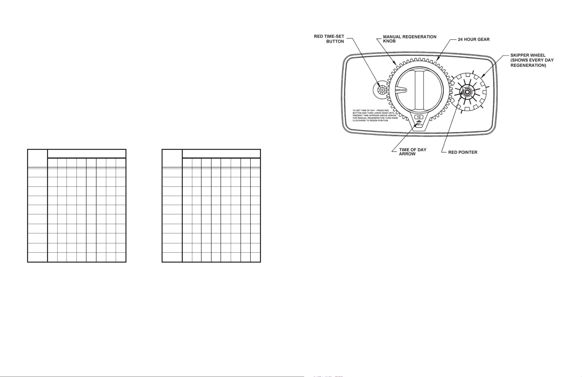
Rotate the skipper wheel until the number "1" is at the red pointer. Set the days that regeneration is to occur by sliding tabs on the skipper wheel outward to expose trip fi ngers. Each tab is one day. Finger at red pointer is tonight. Moving clockwise from the red pointer,
extend or retract fi ngers to obtain the desired regeneration schedule.
1) Press and hold the red button in to disengage the drive gear.
2) Turn the large gear until the actual time of day is opposite the time of day pointer.
3) Release the red button to again engage the drive gear.
4) Time of regeneration is preset for 2:00 a.m.
Turn the manual regeneration knob clockwise.
A slight, clockwise movement of the manual regeneration knob engages the program wheel and starts the regeneration program.
The black center knob will make one revolution in the following approximately three hours and stop in the position shown in the drawing
(SERVICE POSITION).
Even though it takes three hours for this center knob
one-third of this time.
In any event, conditioned water may be drawn after rinse water stops fl owing from the water softener drain line.
HOW TO SET DAYS ON WHICH WATER SOFTENER IS TO REGENERATE:
HOW TO SET THE TIME OF DAY:
HOW TO MANUALLY REGENERATE THE WATER SOFTENER AT ANY TIME.
to complete one revolution, the regeneration cycle of the unit might be set only
3-1
3-2
 Loading...