

Page 1
Installing the Desktop Stand
ET 350 Monitor and ET 3250/55 Computers
Intended Use
When properly installed using the materials provided,
and according to these instructions, the desktop stand is
intended to mount the ET 350 monitor and the
ET 3250/55 computers for use on desktop or other flat
surface.
Warning
Read and understand all safety information
before installing and using this product.
To reduce the risk of fire or electric shock
which could result in serious personal injury or
death:
! Follow all product and accessory installation
instructions.
Caution
To reduce the risk of the ET unit tipping over,
which may result in minor or moderate
personal injury:
Tool required
! Phillips No. 2 torque screwdriver
Installing the desktop stand
The desktop stand is a three-piece assembly:
! Pivot plate with rubber foot attaches to the bottom
of the unit.
! Mounting bracket attaches to the back of the unit.
! Angle bracket attaches to the mounting bracket.
Place foam pads or other material on a flat surface to
protect the unit’s bezel and touch screen and set the
ET unit face-down on this surface while installing the
desktop stand.
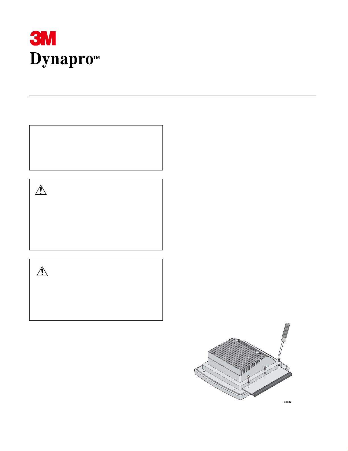
Attaching the pivot plate
1. Through each of three #10-32 ½-inch screws,
thread a lock washer.
2. Thread the screws with lock washers through the
three holes on the back of the pivot plate.
3. Position the pivot plate so that each screw is
aligned with a hole on the back of the unit
Do not open the bezel of the unit while it is mounted on the desktop stand.
Equipment
Materials provided
The Desktop Stand Kit includes:
! 1 pivot plate with rubber foot
! 1 mounting bracket
! 1 angle bracket with rubber foot
! 1 knob
! 7 #10-32 ½-inch screws and lock washers
4. Use the screwdriver to tighten the screws to a
torque of 10 inch-pounds.
Page 2
Installing the Desktop Stand 3M Dynapro ET 350 Monitor and ET 3250/55 Computers
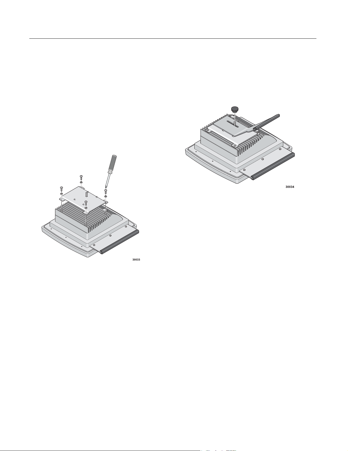
Attaching the mounting bracket
1. Thread one of each of the remaining four lock
washers through one of each of the remaining
four screws.
2. Thread the screws and lock washers through the
four holes on the back of the mounting bracket.
3. Position the mounting bracket so that each is
aligned with a hole on the back of the unit.
4. Use the screwdriver to tighten the screws to a
torque of 10 inch-pounds
Attaching the angle bracket
Use the knob provided to attach the angle bracket to
the mounting bracket. To adjust the viewing angle of
the display up or down, slide the angle bracket up or
down in the slot before tightening the knob.
13892 (Rev. 1.1) Page 2
Page 3

Copyright
This manual is © 3M 2002. All rights reserved.
Reproduction of the contents of this copyrighted manual in
whole or in part, by any means, electronic or mechanical,
for any purpose, without written permission of 3M Touch
Systems, a subsidiary of 3M, is prohibited.
Notice
Given the variety of factors that can affect the use and
performance of a 3M Touch Systems Product, including
that solid state equipment has operation characteristics
different from electromechanical equipment, some of
which factors are uniquely within User's knowledge and
control, it is essential that User evaluate the 3M Touch
Systems product to determine whether it is suitable for
User’s particular purpose and suitable for User’s method of
application. 3M Touch Systems’ statements,
engineering/technical information, and recommendations
are provided for User’s convenience, but their accuracy or
completeness is not warranted. 3M Touch Systems
products are not specifically designed for use in medical
devices as defined by United States federal law. 3M Touch
Systems products should not be used in such applications
without 3M Touch Systems’ express written consent. User
should contact its sales representative if User’s opportunity
involves a medical device application.
Important notice to purchaser
Specifications are subject to change without notice. 3M
Touch Systems’ Products are warranted to meet their
published specifications from the date of shipment and for
the period stated in the specification. 3M Touch Systems
makes no additional warranties, express or implied,
including but not limited to any implied warranties of
merchantability or fitness for a particular purpose.
User is responsible for determining whether the 3M Touch
Systems Products are fit for User’s particular purpose and
suitable for its method of production, including intellectual
property liability for User's application. If a Product is
proven not to have met 3M Touch Systems’ warranty, then
3M Touch Systems’ sole obligation and User’s and
Purchaser’s exclusive remedy, will be, at 3M Touch
Systems’ option, to repair or replace that Product quantity
or to refund its purchase price. 3M Touch Systems has no
obligation under 3M Touch Systems’ warranty for any
Product that has been modified or damaged through
misuse, accident, neglect, or subsequent manufacturing
operations or assemblies by anyone other than 3M Touch
Systems. 3M Touch Systems shall not be liable in any
action against it in any way related to the Products for
any loss or damages, whether non-specified direct,
indirect, special, incidental or consequential (including
downtime, loss of profits or goodwill) regardless of the
legal theory asserted.
(11/01)
Edition
Second edition: January 2002
Document Number: 13892 (Rev. 1.1)
Trademark
3M Dynapro is a trademark of 3M.
Page 4

3M Touch Systems
3M Optical Systems Division
800 Carleton Court
Annacis Island
New Westminster, BC
Canada V3M 6L3
www.3Mtouch.com
Worldwide Manufacturing Plants
Austin, Texas
Methuen, Massachusetts
Milwaukee, Wisconsin
Vancouver, BC, Canada
Abingdon, UK
For more information on 3M touch products, visit
3Mtouch.com or call toll-free 1-800-667-0374.
© 3M 2002
13892 (Rev. 1.1)
 Loading...