

Page 1

ET 3170 Terminal (Series B)
User’s Installation Guide
Read and understand all safety information
before installing and using this product.
3M Touch Systems Proprietary Information
Page 2

Copyright
This manual is © 3M 2002. All rights reserved.
Reproduction of the contents of this copyrighted manual in whole or in part, by
any means, electronic or mechanical, for any purpose, without written permission
of 3M Touch Systems, a subsidiary of 3M, is prohibited.
Notice
Important notice to
purchaser
Given the variety of factors that can affect the use and performance of a 3M
Touch Systems Product (the “Product”), including that solid state equipment has
operation characteristics different from electromechanical equipment, some of
which factors are uniquely within User’s knowledge and control, it is essential
that User evaluate the 3M Touch Systems Product and software to determine
whether it is suitable for User’s particular purpose and suitable fo r User’s method
of application. 3M Touch Systems’ statements, engineering/technical
information, and recommendations are provided for User’s convenience, but
their accuracy or completeness is not warran ted. 3M Touch Systems products and
software are not specifically designed for use in medical devices as defined by
United States federal law. 3M Touch Systems products and software should not
be used in such applications without 3M Touch Systems’ express written
consent. User should contact its sales representative if User’s opportunity
involves a medical device application.
Specifications are subject to change without notice. These 3M Touch Systems’
Products and software are warranted to meet their published specifications from
the date of shipment and for the period stated in the specification. 3M Touch
Systems makes no additional warranties, express or implied, including but
not limited to any implied warranties of merchantability or fitness for a
particular purpose.
User is responsible for determining whether the 3M Touch Systems Products and
software are fit for User’s particular purpose and suitable for its method of
production, including intellectual property liability for User's application. If the
Product, software or software media is proven not to have met 3M Touch
Systems’ warranty, then 3M Touch Systems’ sole obligation and User’s and
Purchaser’s exclusive remedy, will be, at 3M Touch Systems’ option, to repair
or replace that Product quantity or software media or to refund its purchase price.
3M Touch Systems has no obligation under 3M Touch Systems’ warranty for any
Product, software or software media that has been modified or damaged through
misuse, accident, neglect, or subsequent manufacturing operations or assemblies
by anyone other than 3M Touch Systems. 3M Touch Systems shall not be liable
in any action against it in any way related to the Products or software for any
loss or damages, whether non-specified direct, indirect, special, incidental or
consequential (including downtime, loss of profits or goodwill) regardless of
the legal theory asserted.
Edition
T rademarks
Document Number: 19914 (Rev. 1.0).
October 2002
(Supersedes 11754)
3M Dynapro, MicroTouch, and Near Field Imaging are trademarks of 3M.
3M Touch Systems Proprietary Information
Page 3
Intended use
Safety notices
Important Safety Information
Read and understand all safety information before using the 3M DynaproTM
ET 3170 terminal. Follow all instructions marked on the product and described in
this document. Pay close attention to the statement of intended use and the safety
notices.
The 3M Dynapro ET 3170 terminal is intended to provide touch screen functions
for industrial applications when the terminal is connected to a host computer. The
ET 3170 terminal is not intended for use in hazardous locations. Using the
terminal in conditions exceeding these ratings will invalidate the warranty and
will be solely the user’s risk and responsibility. The ET 3170 terminal is a
component. After the terminal is installed, the whole system of which it is a part
must be inspected to confirm seal ratings and compliance with all local electrical
codes.
DANGER
To reduce the risks associated with fire and explosion which, if not avoided, will
cause death or serious injury and/or property damage:
! Do not install or use the ET unit in a hazardous location.
WARNING
To reduce the risks associated with fire and explosion which, if not avoided, could
result in death or serious injury and/or property damage:
! Refer to the cleaner manufacturer’s material safety data sheet and follow all instructions
and recommendations.
! Do not use flammable or combustible cleaners.
WARNING
To reduce the risks associated with electrical shock or fire which, if not avoided,
could result in death or serious injury and/or property damage:
! Engineer the installation of the ET unit to take into account the operating environment (e.g.,
thermal, shock/vibration factors).
! Install the ET unit close to the power source so the unit can be easily and q uickly
disconnected. For permanently connected equipment, a readily accessible disconnect
device must be incorporated in the fixed wiring.
! Follow all product and accessory installation instructions.
! Any servicing or other procedures not described in this manual are to be performed only by
3M Touch Systems service personnel.
! To ensure compliance with electrical codes and safe operation of the ET unit, have a
licensed journeyman electrician familiar with local and federal codes perform all wiring
tasks.
! When connecting power with fixed field wiring, the power cable must be double insulated.
A clear, flexible insulator (supplied) must cover the portion of the cable that is not double
insulated when connecting to a terminal strip connector.
3M Touch Systems Proprietary Information
i
Page 4
3M Dynapro ET 3170 Terminal User’s Installation Guide
WARNING
To reduce the risks associated with electrical shock or fire which, if not avoided,
could result in death or serious injury and/or property damage:
! Provide a clean, reliable grounding.
! When installing the ET unit, ensure that specifications for supply circuit overcurrent
protection and wiring are not exceeded.
! Properly install the ET unit with a NEMA 4X/IP66 gasket that is undamaged and effective.
! Do not use an ET unit that is not rated to NEMA 4X/IP66 in an environment that requires a
NEMA 4X/IP66 seal.
! When replacing a fuse of other part, use a part of the type and rating specified by 3M Touch
Systems.
WARNING
To reduce the risks associated with electrical shock which, if not avoided, could
result in death or serious injury and/or property damage:
! Do not open the power supply in the ET unit. It contains hazardous voltages. The power
supply has no user-serviceable parts or adjustments inside.
! Make sure that the ground potential difference between the ET unit and the host computer
is less than 2V.
! Qualified service personnel should avoid exposed electrical contacts inside the ET unit.
! Before removing the ET unit from its mounting or performing any other service to the unit,
disconnect power to the unit.
! Provide adequate strain relief for all communications and power cables.
CAUTION
To reduce the risks associated with fire and electrical shock that may result in
personal injury or property damage:
! If the ET unit will be used in corrosive environments, it is the responsibility of the user to
test and evaluate the unit in those environments. The ET unit, as shipped, has not been
evaluated for use in corrosive environments and using it in such environments, without
evaluation and testing, may lead to unsafe conditions.
CAUTION
To reduce the risks associated with fire which, if not avoided, could result in property
damage:
! Use only installation materials supplied. Use of materials other than those supplied may
result in uneven mechanical loading and will invalidate the warranty.
CAUTION
To reduce the risks associated with muscle strain which, if not avoided, may result
in minor or moderate injury:
! Avoid using the ET unit for long periods of time without breaks.
CAUTION
To reduce the risks associated with eye strain which, if not avoided, may result in
minor or moderate injury:
! Use the ET unit where there is neither too much ambient light nor glare on the screen.
CAUTION
To reduce the risks associated with environmental contamination which, if not
avoided, may result in minor or moderate injury and/or cause property damage:
! Dispose of the ET unit according to applicable government regulations.
3M Touch Systems Proprietary Information
ii
Page 5
Important Safety Information
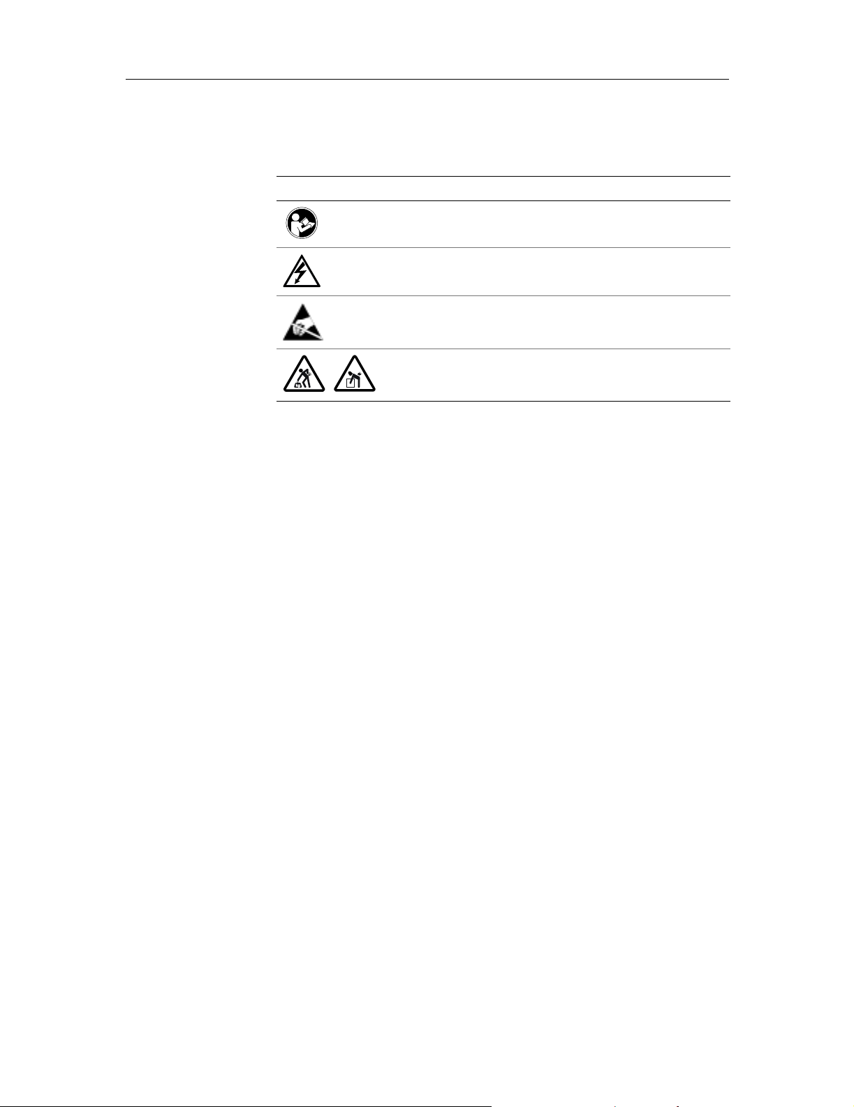
Safety labels
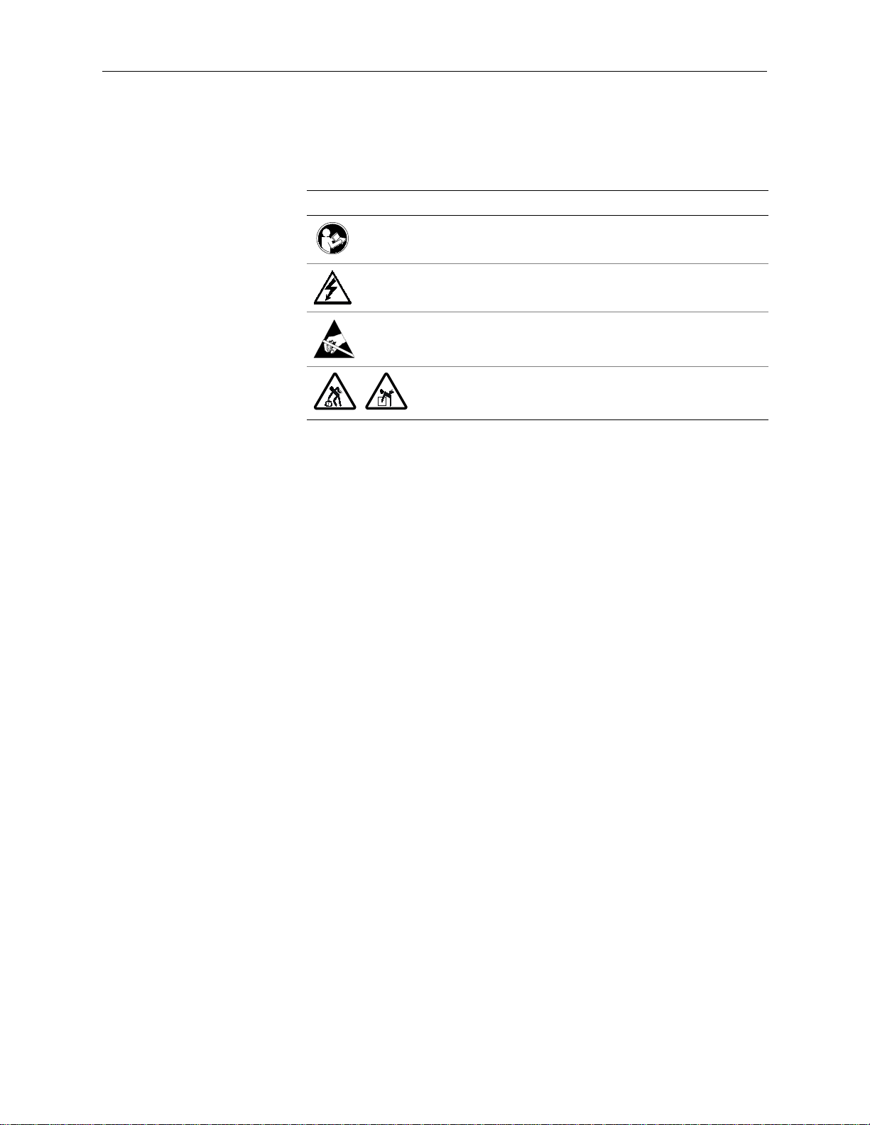
The following safety symbols appear on your 3M Dynapro industrial product and
its packaging materials:
Symbol Meaning
Consult user instructions.
Caution: Risk of electric shock.
Caution: Item is susceptible to electrostatic discharge (ESD)
damage if proper precautions are not taken.
Lifting hazard
3M Touch Systems Proprietary Information
iii
Page 6

Page 7
Utilisation
Information importante
sur la sécurité
Lire les renseignements de sécurité et les comprendre avant d’utiliser le terminal
Dynapro ET 3170 de 3M. Suivre toutes les instructions indiquées sur le produit et
décrites dans le présent manuel. Prêter une attention spéciale au mode d’emploi et
aux avis de sécurité.
Le terminal Dynapro ET 3170 de 3M est conçu pour servir à l’exécution de fonctions au moyen d’un écran tactile dans les utilisations industrielles où le terminal
est raccordé à un ordinateur hôte. Le terminal Dynapro ET 3170 n’est pas destiné
à servir dans des endroits à risque. L’emploi du terminal dans des conditions qui
excèdent les valeurs nominales prescrites entraîne l’annulation de la garantie et relève de la seule responsabilité de l’utilisateur. Le terminal Dynapro ET 3170 est
un composant. Après l’installation du terminal, il faut procéder à la vérification de
l’ensemble du système dont il fait partie afin d’en certifier l’étanchéité nominale
et la conformité aux codes locaux de l’électricité.
Avis de sécurité
DANGER
Pour réduire les risques d’explosion et d’incendie susceptibles, faute de précaution,
de causer la mort, des blessures graves ou des dommages matériels :
Ne pas installer le terminal ET dans un endroit à risque.
AVERTISSEMENT
Pour réduire les risques d’explosion et d’incendie susceptibles, faute de précaution,
de causer la mort, des blessures graves ou des dommages matériels :
Prière de suivre les instructions et les recommandations prescrites par le fabricant de pro-
duits de nettoyage et d'en consulter la fiche toxicologique.
Ne pas utiliser de produits de nettoyage inflammables ou combustibles.
AVERTISSEMENT
Pour réduire les risques d’incendie et d’électrocution susceptibles, faute de précaution, de causer la mort, des blessures graves ou des dommages matériels :
Prévoir l’installation du terminal ET en tenant compte de l’environnement de service (fac-
teurs de température, de vibrations ou de chocs par exemple).
Installer le terminal ET près de la source d’alimentation afin de pouvoir le débrancher faci-
lement et rapidement. Pour l’équipement branché en permanence, un dispositif de débranchement facile d’accès doit être incorporé au fixe câblage.
Suivre toutes les instructions d’installation du produit et des accessoires.
Tout entretien ou autre procédure qui n’est pas décrite dans ce manuel doit être réalisée
seulement par le personnel du service de 3M Touch Systems.
Pour s’assurer du fonctionnement sécuritaire du terminal ET et de sa conformité aux codes
de l’électricité, demander à un électricien compétent agréé familier avec les codes locaux
et fédéraux d’en effectuer le câblage.
Lors du branchement à l’alimentation au moyen d’un dispositif de câblage à champ fixe, le
câble d’alimentation doit comporter une double gaine isolante. Un isolant transparent et
flexible (fourni) doit recouvrir la portion du câble ne comportant pas de double gaine isolante
lors du branchement à un connecteur de bornier.
Données brevetées 3M Touch Systems
v
Page 8
Guide d’installation et d’utilisation du terminal Dynapro ET 3170 de 3M
AVERTISSEMENT
Pour réduire les risques d’incendie et d’électrocution susceptibles, faute de précaution, de causer la mort, des blessures graves ou des dommages matériels :
Fournir une mise à terre fiable et propre.
Lors de l’installation du terminal ET, veiller à ne pas dépasser les normes de câblage et de
protection contre les surcharges du circuit d’alimentation.
Équiper le terminal ET d’un joint NEMA 4X/IP66 efficace et en bon état.
Ne pas utiliser un terminal ET incompatible avec la norme NEMA 4X/IP66 dans un milieu
de service nécessitant l’emploi d’un joint conforme à cette norme.
Pour remplacer un fusible ou un autre composant, utiliser une pièce de rechange de type
et de capacité nominale prescrits par 3M Touch Systems.
AVERTISSEMENT
Pour réduire les risques d’électrocution susceptibles, faute de précaution, de causer
la mort, des blessures graves ou des dommages matériels :
Ne pas ouvrir le bloc d’alimentation du terminal ET. Il contient des tensions dangereuses.
Le bloc d'alimentation ne renferme aucune pièce ni aucun dispositif de réglage remplaçable
par l'utilisateur.
Veiller à ce que la tension de masse entre le terminal ET et l’ordinateur hôte soit inférieure
à 2 volts.
Le personnel d’entretien compétent doit éviter de toucher aux contacts électriques nus du
terminal ET.
Couper l’alimentation du terminal ET avant de le détacher de son dispositif de montage ou
d’y effectuer une réparation quelconque.
Équiper les câbles d'alimentation et de communication d'un réducteur de tension adéquat.
AVERTISSEMENT
Pour réduire les risques d’incendie et d’électrocution susceptibles, faute de précaution, de causer des blessures ou des dommages matériels :
Si le terminal ET doit servir dans une atmosphère corrosive, il incombe à l’utilisateur de le
mettre à l’essai et d’en évaluer l’efficacité dans un tel milieu. Le terminal ET d’origine n’a
pas fait l’objet d’une mise à l’essai en atmosphère corrosive et son emploi dans un tel milieu, sans évaluation ou essai préalable, risque de le rendre non sécuritaire.
AVERTISSEMENT
Pour réduire les risques d’incendie susceptibles, faute de précaution, de causer des
dommages matériels :
Se servir exclusivement des matériaux d’installation fournis. L’emploi de matériaux autres
que ceux fournis risque d’entraîner une charge mécanique inégale et d’annuler la garantie.
AVERTISSEMENT
Pour réduire les risques de tension musculaire susceptibles, faute de précaution, de
causer des blessures légères ou modérées :
Éviter d’utiliser le terminal ET pendant de longues périodes de temps sans pause.
AVERTISSEMENT
Pour réduire les risques de fatigue oculaire susceptibles, faute de précaution, de
causer des blessures légères ou modérées :
Utiliser le terminal ET là où la lumière ambiante ne produit aucun effet d’éblouissement à
l’écran.
AVERTISSEMENT
Pour réduire les risques de contamination environnementale susceptibles, faute de
précaution, de causer des blessures légères ou modérées ou des dommages matériels :
Mettre le terminal ET au rebut en suivant les règles gouvernementales en vigueur.
Données brevetées 3M Touch Systems
vi
Page 9
Information importante sur la sécurité
Étiquettes de sécurité
Les symboles de sécurité suivants apparaissent sur le produit industriel Dynapro
de 3M et sur son emballage :
Symbole Signification des symboles
Consulter le mode d’emploi.
Avertissement : Risque d’électrocution.
Avertissement : À défaut de prendre des mesures de précaution
appropriées, le produit risque de subir des dommages par suite
de décharges électrostatiques.
Risque associé au levage.
Données brevetées 3M Touch Systems
vii
Page 10

Page 11
Voorgenomen gebruik
Belangrijke
veiligheidsinformatie
Voordat de 3M Dynapro™ ET 3170 terminal wordt gebruikt, moet alle veiligheidsinformatie zijn gelezen en begrepen. Volg alle op het product aangegeven en
in dit document beschreven instructies op. Besteed extra aandacht aan de verklaring betreffende het voorgenomen gebruik en de veiligheidskennisgevingen.
De 3M Dynapro™ ET 3170 terminal voorziet in functies op het aanraakscherm
voor industriële toepassingen als de terminal is aangesloten op een hostcomputer.
De ET 3170 terminal is niet bedoeld voor gebruik op gevaarlijke locaties. Gebruik
van de terminal in omstandigheden die niet aan deze toegestane waarden voldoen,
maakt de garantie ongeldig en is uitsluitend voor het risico en de verantwoordelijkheid van de gebruiker. De ET 3170 terminal is een component. Nadat de terminal is geïnstalleerd, moet het gehele systeem waarvan deze deel uitmaakt,
worden gecontroleerd om na te gaan of aan alle afdichtingswaarden en lokale
voorschriften betreffende elektriciteit is voldaan.
Veiligheidskennisgevingen
GEVAAR
Neem het volgende in acht om de risico’s van brand en explosies te reduceren die,
indien deze niet worden voorkomen, ernstig letsel, de dood en/of schade aan eigendommen tot gevolg hebben:
Installeer of gebruik de ET-eenheid niet op een gevaarlijke locatie.
WAARSCHUWING
Neem het volgende in acht om de risico’s van brand en explosies te reduceren die,
indien deze niet worden voorkomen, ernstig letsel, de dood en/of schade aan eigendommen tot gevolg kunnen hebben:
Raadpleeg het veiligheidsinformatieblad van de reinigingsfabrikant en volg de instructies en
adviezen op.
Gebruik geen ontvlambare of brandbare reinigingsmiddelen.
Informatie aangaande eigendomsrechten 3M Touch Systems
ix
Page 12
Installatiehandleiding 3M Dynapro ET 3170 terminal voor de gebruiker
WAARSCHUWING
Neem het volgende in acht om de risico’s van elektrische schokken of brand te reduceren die, indien deze niet worden voorkomen, ernstig letsel, de dood en/of schade
aan eigendommen tot gevolg kunnen hebben:
Houd bij het plannen van de installatie van de ET-eenheid rekening met de werkconfiguratie
(bijv. thermische factoren en factoren als schokken en vibratie).
Installeer de ET-eenheid in de buurt van de voedingsbron zodat de eenheid snel en een-
voudig kan worden losgekoppeld. Voor permanente installaties moet er een gemakkelijk
toegankelijke schakelaar in de vaste bedrading aanwezig zijn.
Volg nauwkeurig de installatie-instructies van dit product en de eventuele accessoires op.
Alle onderhoudswerkzaamheden die niet beschreven worden in deze handleiding, moeten
uitsluitend worden uitgevoerd door 3M Touch Systems onderhoudspersoneel.
Laat alle bedradingswerkzaamheden uitvoeren door een erkende, gerenommeerde elektri-
cien die bekend is met de lokale en landelijke voorschriften om er zeker van te zijn dat aan
alle voorschriften betreffende elektriciteit is voldaan en om een veilige werking van de ETeenheid te garanderen.
Als de voeding wordt aangesloten door middel van vaste veldbedrading moet de voedings-
kabel dubbel zijn geïsoleerd. Een schone en flexibele isolator (meegeleverd) moet het gedeelte waar de kabel niet volledig dubbel is geïsoleerd bedekken wanneer deze wordt
aangesloten op een verbindingsstrip connector.
WAARSCHUWING
Neem het volgende in acht om de risico’s van elektrische schokken of brand te reduceren die, indien deze niet worden voorkomen, ernstig letsel, de dood en/of schade
aan eigendommen tot gevolg kunnen hebben:
Zorg voor een schone en betrouwbare aardleiding.
Zorg ervoor dat bij de installatie van de ET-eenheid de specificaties voor beveiliging tegen
overbelasting en bedrading van het voedingscircuit niet worden overschreden.
Installeer de ET-eenheid op juiste wijze met een onbeschadigde en effectieve NEMA 4X/
IP66-pakking.
Gebruik ET-eenheden die niet voldoen aan NEMA 4X/IP66 niet in omgevingen waarin een
NEMA 4X/IP66-afdichting vereist is.
Gebruik ter vervanging van zekeringen of andere onderdelen uitsluitend onderdelen van
het type en met de toegestane waarde die door 3M Touch Systems zijn opgegeven.
WAARSCHUWING
Neem het volgende in acht om de risico’s van elektrische schokken te reduceren die,
indien deze niet worden voorkomen, ernstig letsel, de dood en/of schade aan eigendommen tot gevolg kunnen hebben:
Maak de voedingsbron in de ET-eenheid niet open. Deze bevat een gevaarlijk voltage. De
vermogensvoeding bevat geen onderdelen die aanpassing of onderhoud vergen door gebruikers.
Zorg ervoor dat het verschil in aardpotentiaal tussen de ET-eenheid en de hostcomputer
niet meer dan 2V bedraagt.
De blootliggende elektrische contacten in de ET-eenheid mogen niet door gekwalificeerd
onderhoudspersoneel worden aangeraakt.
Voordat de ET-eenheid van de steun wordt verwijderd of er onderhoud aan de eenheid
wordt uitgevoerd, moet de voeding van de eenheid worden losgekoppeld.
Zorg voor voldoende trekontlasting voor alle stroom- en communicatiekabels.
VOORZICHTIG
Neem het volgende in acht om de risico’s van brand en elektrische schokken te reduceren die persoonlijk letsel of schade aan eigendommen tot gevolg kunnen hebben:
Als de ET-eenheid in een corrosieve omgeving wordt gebruikt, is het de verantwoordelijk-
heid van de gebruiker de eenheid in die omgeving te testen en onderzoeken. De ET-eenheid is bij verzending niet onderzocht op gebruik in corrosieve omgevingen en gebruik
ervan in zulke omgevingen zonder tests en onderzoek kan leiden tot onveilige omstandigheden.
Informatie aangaande eigendomsrechten 3M Touch Systems
x
Page 13
Belangrijke veiligheidsinformatie
VOORZICHTIG
Neem het volgende in acht om de risico’s van brand te reduceren die, indien deze niet
worden voorkomen, schade aan eigendommen tot gevolg kunnen hebben:
Gebruik alleen de meegeleverde installatiematerialen. Het gebruik van andere dan de mee-
geleverde materialen kan een onevenwichtige mechanische belasting tot gevolg hebben
waardoor de garantie ongeldig wordt.
VOORZICHTIG
Neem het volgende in acht om de risico’s van spierbelasting te reduceren die, indien
deze niet worden voorkomen, licht tot middelzwaar letsel tot gevolg kunnen hebben:
Gebruik de ET-eenheid niet langdurig zonder pauze te nemen.
VOORZICHTIG
Neem het volgende in acht om de risico’s van asthenopie te reduceren die, indien
deze niet worden voorkomen, licht tot middelzwaar letsel tot gevolg kunnen hebben:
Gebruik de ET-eenheid niet in een omgeving met te veel omgevingslicht of reflecties op het
scherm.
VOORZICHTIG
Neem het volgende in acht om de risico’s van verontreiniging van de omgeving te reduceren die, indien deze niet worden voorkomen, licht tot middelzwaar letsel en/of
schade aan eigendommen tot gevolg kunnen hebben:
Voer de ET-eenheid af in overeenstemming met de van toepassing zijnde overheidsbepa-
lingen.
Veiligheidslabels
De volgende veiligheidssymbolen staan op het industriële 3M Dynapro product en
de verpakkingsmaterialen:
Symbool Betekenis
Raadpleeg de instructies voor de gebruiker.
Waarschuwing: Risico van elektrische schokken
Waarschuwing: Het item is gevoelig voor beschadiging door
elektrostatische ontlading (ESD) als er geen goede voorzorgsmaatregelen worden genomen.
Gevaarlijk om op te tillen
Informatie aangaande eigendomsrechten 3M Touch Systems
xi
Page 14

Page 15
Einsatzbereiche
Wichtige Sicherheitshinweise
Bevor Sie das 3M Dynapro™ ET 3170 Terminal benutzen, müssen Sie alle Sicherheitshinweise gelesen und verstanden haben. Befolgen Sie alle am Produkt
angebrachten und in diesem Dokument beschriebenen Anweisungen. Achten Sie
insbesondere auf die Erklärung zum Einsatzbereich und die Sicherheitshinweise.
Das 3M Dynapro™ ET 3170 Terminal bietet Touch-Screen-Funktionen für industrielle Anwendungen, wenn das Terminal an einen Host-Computer angeschlossen ist. Das ET 3170 Terminal ist nicht für die Verwendung in gefährdeten
Bereichen vorgesehen. Der Einsatz des Terminals unter Bedingungen außerhalb
der Nenndaten macht die Garantie nichtig und erfolgt ausschließlich auf Gefahr
und Verantwortung des Benutzers. Das ET 3170 Terminal ist eine Komponente.
Nach Installation des Terminals muss das gesamte System, dessen Bestandteil das
Terminal ist, untersucht werden, um die Dichtungsdaten und die Einhaltung örtlicher elektrischer Vorschriften zu überprüfen.
Sicherheitshinweise
GEFAHR!
Um Brand- und Explosionsgefahr mit schweren Verletzungs- oder Todesfolgen und/
oder Sachschäden zu vermeiden:
Das ET-Gerät nicht in gefährdeten Bereichen installieren bzw. benutzen.
WARNHINWEISE
Um Brand- und Explosionsgefahr mit möglichen schweren Verletzungs- oder Todesfolgen und/oder Sachschäden zu vermeiden:
Angaben im Sicherheitsdatenblatt des Herstellers beachten und alle Anweisungen und
Empfehlungen befolgen.
Keine entflammbaren oder brennbaren Reiniger verwenden.
3M Touch Systems Firmeneigene Informationen
xiii
Page 16
Bedienungsanleitung für 3M Dynapro ET 3170
WARNHINWEISE
Um Elektroschock- und Brandgefahr mit möglichen schweren Verletzungs- oder Todesfolgen und/oder Sachschäden zu vermeiden:
Bei der Installation des ET-Geräts die Betriebsumgebung (z.B. thermische sowie Erschüt-
terungs-/Vibrationsfaktoren) berücksichtigen.
Das ET-Gerät in der Nähe der Stromquelle aufstellen, so dass das Gerät einfach und
schnell von der Stromversorgung getrennt werden kann. Für Geräte mit dauerhaften elektrischen Anschlüssen ist ein gut zugänglicher Trennschalter in die elektrische Netzleitung
einzubauen.
Alle Montageanweisungen für das Produkt und Zubehör beachten.
Wartungsarbeiten und andere nicht in diesem Handbuch beschriebene Prozeduren dürfen
nur vom Servicepersonal von 3M Touch Systems ausgeführt werden.
Um die Einhaltung örtlicher elektrischer Vorschriften sowie den sicheren Betrieb des ET-
Geräts zu gewährleisten, sollte ein lizenzierter gelernter Elektriker, der sich mit den örtlichen und nationalen Vorschriften auskennt, die elektrische Installation vornehmen.
Wenn die Stromversorgung über fest installierte Kabel geführt wird, müssen diese Kabel
doppelt isoliert sein. Ein durchsichtiger und flexibler Isolator (mitgeliefert) muss beim Anschluss an die Klemmenleiste jeweils das nicht doppelt isolierte Kabelteil abdecken.
WARNHINWEISE
Um Elektroschock- und Brandgefahr mit möglichen schweren Verletzungs- oder Todesfolgen und/oder Sachschäden zu vermeiden:
Sorgen Sie für saubere und zuverlässige Erdung.
Bei der Installation des ET-Geräts sicherstellen, dass die Spezifikationen für Überstrom-
schutz des Speisestromkreises und Kabels nicht überschritten werden.
Das ET-Gerät ordnungsgemäß mit einer unbeschädigten und wirksamen NEMA 4X/IP66-
Dichtung installieren.
Ein ET-Gerät, das nicht für NEMA 4X/IP66 ausgelegt ist, in nicht einer Umgebung einset-
zen, die eine NEMA 4X/IP66-Dichtung erfordert.
Beim Ersetzen einer Sicherung oder eines anderen Bauteils muss das Teil dem Typ und
den Nenndaten entsprechen, die von 3M Touch Systems festgelegt wurden.
WARNHINWEISE
Um Elektroschockgefahr mit möglichen schweren Verletzungs- oder Todesfolgen
und/oder Sachschäden zu vermeiden:
Netzteil im ET-Gerät nicht öffnen. Es liegen gefährliche Spannungen an. Das Netzteil ent-
hält keine Teile oder Einstellungsmöglichkeiten, die von Benutzern gewartet werden können.
Sicherstellen, dass der Massepotentialunterschied zwischen dem ET-Gerät und dem Host-
Computer weniger als 2 V beträgt.
Qualifizierte Servicetechniker sollten im Innern des ET-Geräts freiliegende elektrische Kon-
takte vermeiden.
Vor der Demontage des ET-Geräts aus seiner Halterung bzw. vor Wartungsarbeiten am
Gerät die Stromversorgung zum Gerät unterbrechen.
Achten Sie auf geeignete Zugentlastung der Fernmeldekabel und Netzkabel.
VORSICHT
Um Elektroschock- und Brandgefahr mit möglichen Verletzungsfolgen oder Sachschäden zu vermeiden:
Wenn das ET-Gerät in korrosiven Umgebungen eingesetzt wird, obliegt es dem Benutzer,
das Gerät in diesen Umgebungen zu testen und zu bewerten. Das ET-Gerät wurde nicht
für den Einsatz in korrosiven Umgebungen bewertet. Daher kann der Einsatz in derartigen
Umgebungen ohne vorherige Bewertung und Tests zu unsicheren Bedingungen führen.
3M Touch Systems Firmeneigene Informationen
xiv
Page 17

Wichtige Sicherheitshinweise
VORSICHT
Um Brandgefahr mit möglichen Sachschäden zu vermeiden:
Nur das im Lieferumfang enthaltene Installationsmaterial verwenden. Die Verwendung von
nicht im Lieferumfang enthaltenem Material kann zu einer ungleichmäßigen mechanischen
Belastung führen und die Garantie nichtig machen.
VORSICHT
Um Gefahren von Muskelüberlastungen mit möglichen leichten oder moderaten Verletzungsfolgen zu vermeiden:
Das ET-Gerät nicht über einen längeren Zeitraum ohne Pausen verwenden.
VORSICHT
Um Gefahren von Augenüberlastungen mit möglichen leichten oder moderaten Verletzungsfolgen zu vermeiden:
Das ET-Gerät nicht in Umgebungen mit zu starkem Umgebungslicht bzw. Blendeffekten auf
dem Bildschirm einsetzen.
VORSICHT
Um die Gefahr der Umweltbelastung mit möglichen leichten oder moderaten Verletzungsfolgen und/oder Sachschäden zu vermeiden:
Das ET-Gerät entsprechend den geltenden gesetzlichen Vorschriften entsorgen.
Sicherheitssymbole
Die folgenden Sicherheitssymbole sind auf Ihrem 3M Dynapro und dessen Verpackung abgebildet:
Symbole Bedeutung der Symbole
Lesen Sie bitte in der Bedienungsanleitung nach.
Vorsicht: Elektroschockgefahr.
Vorsicht: Wenn keine geeigneten Maßnahmen getroffen werden, kann dieses Gerät durch elektrostatische Entladung beschädigt werden.
Verletzungsgefahr durch Heben
3M Touch Systems Firmeneigene Informationen
xv
Page 18

Page 19
Importanti informazioni sulla
sicurezza
Si prega di leggere ed assimilare bene tutte le norme di sicurezza prima di utilizzare il terminale Dynapro™ ET 3170 di 3M. Seguire tutte le istruzioni indicate sul
prodotto e descritte nel presente documento. Si prega di leggere con particolare attenzione la dichiarazione relativa alla destinazione d’uso e le avvertenze di sicurezza.
Applicazioni d’impiego del prodotto
Il terminale Dynapro™ ET 3170 di 3M è destinato ad essere utilizzato come "touch screen" o schermo tattile per applicazioni industriali tramite il collegamento ad
un host computer. Il terminale ET 3170 non può essere utilizzato in ambienti o postazioni pericolose. Qualora il terminale venisse utilizzato in condizioni diverse da
quelle indicate nei valori ammessi, la relativa garanzia sarà nulla e l’utilizzo
dell’apparecchiatura sarà ad esclusivo rischio e pericolo dell’utente. Il terminale
ET 3170 è un componente. Una volta installato il terminale, occorrerà ispezionare
l’intero sistema di cui esso fa parte al fine di confermare la taratura delle tenute e
la conformità a tutte le norme in vigore localmente in materia di impianti elettrici.
Informazioni relative alla sicurezza
PERICOLO
Per ridurre i rischi associati ad incendio ed esplosione che, se non evitati, possono
causare la morte o il ferimento grave di persone e/o il danneggiamento di cose:
Non installare, né utilizzare il terminale ET in luoghi pericolosi.
AVVERTENZA
Per ridurre i rischi associati ad incendio ed esplosione che, se non evitati, possono
causare la morte o il ferimento grave di persone e/o il danneggiamento di cose:
Consultare le istruzioni per la sicurezza nell’uso dei materiali e seguire attentamente le
istruzioni e i consigli del produttore.
Per la pulizia non utilizzare prodotti infiammabili o combustibili.
Informazioni sui Sistemi 3M Touch soggette a diritti di proprietà
xvii
Page 20
Guida all’Installazione del Terminale ET 3170 Dynapro di 3M per l’Utente
AVVERTENZA
Per ridurre i rischi associati ad incendio ed esplosione che, se non evitati, possono
causare la morte o il ferimento grave di persone e/o il danneggiamento di cose:
Programmare l’installazione dell’unità ET tenendo conto dell’ambiente in cui verrà utilizzato
(condizioni termiche, possibili rischi di urto/vibrazione).
Installare l’unità ET vicino ad una fonte di alimentazione, in modo da poterlo scollegare age-
volmente. Per i dispositivi collegati in modo permanente, installare un dispositivo di scollegamento di facile accesso e incorporato nei cavi di alimentazione.
Seguire tutte le istruzioni per l’installazione del prodotto e dei suoi accessori.
Per operazioni di manutenzione o altre procedure non descritte in questo manuale, rivol-
gersi solo a personale di assistenza 3M Touch Systems.
Per garantire la conformità alle norme vigenti in materia di impianti elettrici e ai requisiti di
sicurezza per il funzionamento dell’unità ET, far eseguire tutte le operazioni di cablaggio da
un elettricista qualificato e munito di licenza che conosca bene le leggi locali e nazionali.
Munire il cavo di alimentazione di doppio isolamento mentre si collegano i cavi fissi di cam-
po alla fonte di energia elettrica. Il segmento di cavo utilizzato per il collegamento a un terminale a morsettiera deve essere dotato di un isolatore flessibile e trasparente (in
dotazione) che deve coprire la porzione di cavo priva di doppio isolamento.
AVVERTENZA
Per ridurre i rischi associati ad incendio ed esplosione che, se non evitati, possono
causare la morte o il ferimento grave di persone e/o il danneggiamento di cose:
Installare una messa a terra sicura e affidabile.
Durante l’installazione dell’unità ET fare attenzione a non superare i valori indicati nelle spe-
cifiche per i cablaggi e la protezione dalla sovracorrente nel circuito di alimentazione.
Installare l’unità ET in modo idoneo, con una guarnizione 4X/IP66 NEMA che sia integra ed
efficace.
Non utilizzare apparecchi ET che non siano tarati ai valori 4X/IP66 NEMA in un ambiente
in cui si necessita di una guarnizione 4X/IP66 NEMA.
Quando occorre sostituire un fusibile o altro componente, usare parti di ricambio del tipo e
classificazione indicati per i Sistemi 3M Touch.
AVVERTENZA
Per ridurre i rischi associati a scossa elettrica che, se non evitati, possono causare
la morte o il ferimento grave di persone e/o il danneggiamento di cose:
Non aprire l’alimentatore dell’unità ET. Esso contiene parti sotto tensione elevata. L’alimen-
tatore non contiene parti che richiedono manutenzione o regolazione da parte degli utenti.
Assicurarsi che la differenza di potenziale della massa tra l’unità ET e l’host computer sia
inferiore a 2V.
Il personale qualificato addetto alla manutenzione eviterà di lasciare contatti elettrici esposti
all’interno dell’unità ET.
Prima di staccare l’unità ET dalla propria base o di eseguire qualsiasi altra operazione di
manutenzione alla stessa, scollegare l’alimentazione elettrica.
Evitare di sottoporre i cavi per l’alimentazione e per i segnali a sforzi meccanici.
ATTENZIONE
Per ridurre i rischi associati ad incendio e scossa elettrica che possono ferire e danneggiare cose e persone:
Se l’unità ET è destinata all’uso in ambienti esposti a corrosione, l’utente è tenuto a testarla
e valutarla in relazione alle condizioni previste di utilizzo. Nelle condizioni di spedizione,
l’unità ET non è stata sottoposta a valutazione per l’utilizzo in ambienti esposti a corrosione;
pertanto, il suo utilizzo in tali ambienti senza le idonee prove e valutazioni preventive può
non essere sicuro.
Informazioni sui Sistemi 3M Touch soggette a diritti di proprietà
xviii
Page 21
Importanti informazioni sulla sicurezza
ATTENZIONE
Per ridurre i rischi associati ad incendio che, se non evitati, possono causare il danneggiamento delle apparecchiature:
Per l’installazione usare esclusivamente i materiali forniti. L’utilizzo di materiali diversi da
quelli forniti può creare condizioni di carico meccanico irregolari e rende nulla la garanzia.
ATTENZIONE
Per ridurre i rischi associati a sforzo muscolare che, se non evitati, possono causare
danni lievi o moderati alla salute:
Evitare di usare l’unità ET per lunghi periodi di tempo senza interruzioni.
ATTENZIONE
Per ridurre i rischi associati a sforzo oculare che, se non evitati, possono causare
danni lievi o moderati alla salute:
Usare l’unità ET in ambienti non troppo illuminati o dove non vi sia riverbero sullo schermo.
ATTENZIONE
Per ridurre i rischi associati ad inquinamento dell’ambiente che, se non evitati, possono causare danni lievi o moderati alla salute e/o danneggiare le apparecchiature:
Smaltire l’unità ET secondo le vigenti norme locali.
Etichette di sicurezza
Sul vostro prodotto industriale Dynapro 3M e sul relativo materiale da imballaggio saranno esposti i seguenti simboli:
Simboli Significato dei simboli
Consultare le istruzioni per l’utente
Attenzione: rischio di scossa elettrica
Attenzione: la mancata osservanza delle norme di sicurezza
consigliate può rendere l’articolo soggetto a danni dovuti a scarica elettrostatica.
Attenzione ai rischi durante le operazioni di sollevamento
Informazioni sui Sistemi 3M Touch soggette a diritti di proprietà
ix
Page 22

Page 23
Propósito
Avisos de seguridad
Información importante de
seguridad
Lea y comprenda la información completa de seguridad antes de utilizar la Terminal 3M Dynapro™ ET 3170. Siga las instrucciones marcadas en el producto y que
se describen en este documento. Preste mucha atención a la indicación sobre el
propósito del producto y los avisos de seguridad.
El propósito de la Terminal 3M Dynapro™ ET 3170 es proporcionar funciones de
pantalla de tacto para aplicaciones industriales cuando ésta se conecta a la computadora host. La Terminal ET 3170 no fue diseñada para utilizarse en lugares peligrosos. El uso de la terminal en condiciones que superen estos valores, anulará
la garantía y será riesgo y responsabilidad exclusivamente del usuario. La Terminal ET 3170 es un componente. Después de instalar la terminal, el sistema completo, del cual forma parte, se debe inspeccionar para confirmar las frecuencias del
sello y el cumplimiento con todos los códigos locales de electricidad.
PELIGRO
Para reducir los riesgos asociados con incendios y explosión, los cuales, si no se
evitan, pueden ocasionar la muerte o serias lesiones o daños a la propiedad:
No instale o utilice la unidad ET en un lugar peligroso.
ADVERTENCIA
Para reducir los riesgos asociados con incendios y explosión, los cuales, si no se
evitan, pueden ocasionar la muerte o serias lesiones o daños a la propiedad:
Consulte la Ficha técnica sobre seguridad de materiales del fabricante y siga todas las in-
strucciones y recomendaciones.
No utilice limpiadores inflamables o combustibles.
ADVERTENCIA
Para reducir los riesgos asociados con choque eléctrico o incendios, los cuales, si
no se evitan, pueden ocasionar la muerte o serias lesiones o daños a la propiedad:
Realice ingeniería en la instalación de la unidad ET para tomar en cuenta el ambiente de
funcionamiento (p. Ej., factores térmicos, choque/vibración).
Instale la unidad ET cerca de la fuente de alimentación de manera que la unidad se pueda
desconectar fácil y rápidamente. Para el equipo conectado de manera permanente, habrá
que incorporar al cableado fijo un dispositivo de desconexión de rápido acceso.
Siga todas las instrucciones de instalación del producto y sus accesorios.
Todo procedimiento de mantenimiento o de otro tipo no descrito en este manual deberá ser
realizado, exclusivamente, por el personal de mantenimiento de 3M Touch Systems.
Para asegurar el cumplimiento con los códigos de electricidad y funcionamiento seguro de
la unidad ET, contrate a un electricista conocido con códigos locales y federales para realizar todas las tareas de cableado.
Cuando conecte la alimentación con el cableado fijo de campo, el cable de alimentación
debe ser de doble aislamiento. Un aislante transparente y flexible (que se provee con el
equipo) debe cubrir la porción del cable que no tiene aislamiento doble cuando se conecte
al conector de regletas terminales.
Información patentada de 3M Touch Systems
xxi
Page 24
Guía del usuario para la instalación de la Terminal 3M Dynapro ET 3170
ADVERTENCIA
Para reducir los riesgos asociados con choque eléctrico o incendios, los cuales, si
no se evitan, pueden ocasionar la muerte o serias lesiones o daños a la propiedad:
Proporcione una tierra limpia y confiable.
Cuando instale la unidad ET, asegúrese de no exceder las especificaciones para suminis-
trar protección por sobrecorriente al circuito y cableado.
Instale adecuadamente la unidad ET con una junta NEMA 4X/IP66 que no tenga daños y
funcione.
No utilice una unidad ET que no esté clasificada de acuerdo con NEMA 4X/IP66 en un am-
biente que requiera un sello NEMA 4X/IP66.
Cuando reemplace un fusible de otra pieza, utilice una parte del tipo y clasificación especi-
ficadas por 3M Touch Systems.
ADVERTENCIA
Para reducir los riesgos asociados con choque eléctrico, los cuales, si no se evitan,
pueden ocasionar la muerte o serias lesiones o daños a la propiedad:
No abra la fuente de alimentación en la unidad ET. Contiene tensiones peligrosas. La fu-
ente de alimentación no cuenta en su interior con partes o ajustes atendibles por el usuario.
Asegúrese de que la diferencia potencial de tierra entre la unidad ET y la computadora host
sea menor a 2V.
El personal calificado de servicio debe evitar los contactos eléctricos expuestos dentro de
la unidad ET.
Antes de retirar la unidad ET de su montaje o de realizar cualquier tipo de servicio a la un-
idad, desconecte la alimentación de la unidad.
Proporcione la protección adecuada para todos los cables de comunicación y alimentación.
PRECAUCIÓN
Para reducir los riesgos asociados con incendios y choques eléctricos, que pueden
ocasionar lesiones personales o daños a la propiedad:
Si la unidad ET se utilizará en ambientes corrosivos, es responsabilidad del usuario hacer
pruebas y evaluar la unidad en dichos ambientes. La unidad ET, como se envía, no se ha
evaluado para el uso en ambientes corrosivos y su uso en tales ambientes, sin evaluación
y pruebas, puede conducir a condiciones inseguras.
PRECAUCIÓN
Para reducir los riesgos asociados con incendios, los cuales, si no se evitan, pueden
ocasionar daños a la propiedad:
Utilice solamente los materiales de instalación que se proporcionan. El uso de materiales
diferentes a los proporcionados puede ocasionar una carga mecánica irregular, lo cual anulará la garantía.
PRECAUCIÓN
Para reducir los riesgos asociados con tensión muscular, la cual, si no se evita,
puede ocasionar lesiones menores o moderadas:
Evite utilizar la unidad ET por periodos de tiempo prolongados sin recesos.
PRECAUCIÓN
Para reducir los riesgos asociados con tensión ocular, la cual si no se evita, puede
ocasionar lesiones menores o moderadas:
Utilice la unidad ET donde no existe demasiada iluminación ambiental o deslumbrante en
la pantalla.
Información patentada de 3M Touch Systems
xxii
Page 25
Información importante de seguridad
PRECAUCIÓN
Para reducir los riesgos asociados con contaminación ambiental, la cual, si no se
evita, puede ocasionar lesiones menores o moderadas u ocasionar daños a la
propiedad:
Deseche la unidad ET de acuerdo con la reglamentación gubernamental que aplique.
Etiquetas de seguridad
Los siguientes símbolos de seguridad aparecen en el producto industrial y en los
materiales de empaque de 3M Dynapro:
Símbolo Significado de los símbolos
Consulte las instrucciones para el usuario.
Precaución: Riesgo de choque eléctrico.
Precaución: El artículo es susceptible a daño por descarga
electroestática (ESD), si no se toman las precauciones
adecuadas.
Riesgos por levantar
Información patentada de 3M Touch Systems
xxiii
Page 26

Page 27
䞡㽕ᅝֵܼᙃ
䞡㽕ᅝֵܼᙃ
䞡㽕ᅝֵܼᙃ䞡㽕ᅝֵܼᙃ
⫼䗨
⫼䗨
⫼䗨⫼䗨
ᅝܼџ乍
ᅝܼџ乍
ᅝܼџ乍ᅝܼџ乍
Փ⫼ 3M Dynapro
䇋ᣝ✻ѻકϞᴀ᭛Ё䆄ⱘՓ⫼䇈ᯢ䖯㸠᪡ ᑨ⡍߿⊼ᛣ⫼䗨
ᙃ
TM
ET 3170 Terminal Пࠡ
䇋䯙䇏ᑊ⧚㾷᠔᳝ᅝֵܼ
ᅝܼџ乍ⱘໄᯢ
䖲ࠄЏᴎৢ
㾺ᩌሣࡳ㛑
ᴵӊϟՓ⫼ᴀ㒜ッ
Terminal ᰃϔϾ㒘ӊ
㒳䖯㸠Ẕᶹ
䰽
䰽
䰽䰽
ሑৃ㛑䙓ܡ☿♒⟚⚌㗠ᓩ䍋Ҏ䑿Ӹѵ 䋶ѻᤳ༅
ሑৃ㛑䙓ܡ☿♒⟚⚌㗠ᓩ䍋Ҏ䑿Ӹѵ 䋶ѻᤳ༅
ሑৃ㛑䙓ܡ☿♒⟚⚌㗠ᓩ䍋Ҏ䑿Ӹѵ 䋶ѻᤳ༅ሑৃ㛑䙓ܡ☿♒⟚⚌㗠ᓩ䍋Ҏ䑿Ӹѵ 䋶ѻᤳ༅
䇋࣓䰽എড়Ёᅝ㺙Փ⫼ ET 䆒
䄺
䄺
䄺䄺
ሑৃ㛑䙓ܡ☿♒⟚⚌㗠ᓩ䍋Ҏ䑿Ӹѵ 䋶ѻᤳ༅
ሑৃ㛑䙓ܡ☿♒⟚⚌㗠ᓩ䍋Ҏ䑿Ӹѵ 䋶ѻᤳ༅
ሑৃ㛑䙓ܡ☿♒⟚⚌㗠ᓩ䍋Ҏ䑿Ӹѵ 䋶ѻᤳ༅ሑৃ㛑䙓ܡ☿♒⟚⚌㗠ᓩ䍋Ҏ䑿Ӹѵ 䋶ѻᤳ༅
䇋খ䯙⏙⋕ࠖࠊ䗴ଚⱘᴤ᭭ᅝ᭄ܼ
䇋࣓Փ⫼ৃ➗ᯧ➗ⱘ⏙⋕ࠖ
3M DynaproTM ET 3170 Terminal ৃҹЎ⾡ᎹϮᑨ⫼ᦤկ
ET 3170 Terminal ϡ㛑䰽എড়ЁՓ⫼
བ䍙䖛㾘ᅮⱘ
ֱׂᇚ༅ᬜ Ϩ⫼᠋乏㞾㸠ᡓᢙ亢䰽䋷ӏ
ᅝ㺙њᴀ㒜ッПৢ ᖙ乏ᇍᅝ㺙њᴀ㒜ッⱘᭈϾ㋏
ҹ⹂ֱ㒱㓬ㄝ㑻ϔ㟈ᗻヺড়ᔧഄⱘ᠔᳝⬉㾘㣗
ᑊ䙉Ң᠔᳝ⱘ䇈ᯢᓎ䆂
ET 3170
䄺
䄺
䄺䄺
ሑৃ㛑䙓ܡ☿♒⟚⚌㗠ᓩ䍋Ҏ䑿Ӹѵ 䋶ѻᤳ༅
ሑৃ㛑䙓ܡ☿♒⟚⚌㗠ᓩ䍋Ҏ䑿Ӹѵ 䋶ѻᤳ༅
ሑৃ㛑䙓ܡ☿♒⟚⚌㗠ᓩ䍋Ҏ䑿Ӹѵ 䋶ѻᤳ༅ሑৃ㛑䙓ܡ☿♒⟚⚌㗠ᓩ䍋Ҏ䑿Ӹѵ 䋶ѻᤳ༅
ᔧᅝ㺙ET䆒ᯊ ᑨ㗗㰥᪡⦃๗ ՟བ⏽ᑺ ކߏ/䳛ࡼ㋴
䇋ᇚ ET 䆒ᅝ㺙䴴䖥⬉⑤ⱘԡ㕂 ҹ֓㛑ᖿ䗳 ᮍ֓ഄᮁᓔᴀ䆒ⱘ⬉⑤ 㢹㽕ᇚ䆒
Ϣ⬉⑤∌Йᗻഄ䖲
䇋䙉Ң᠔᳝ѻક䜡ӊⱘᅝ㺙䇈ᯢ
ӏԩ㓈ׂᎹ݊ҪᴀᣛЁ≵᳝䇈ᯢⱘ᪡া㛑⬅ 3M Touch Systems 㓈ׂҎ䖯㸠
Ў⹂ֱ ET 䆒ⱘᅝܼ᪡ヺড়⬉㾘㣗 ᳔ད䇋Ꮖ㦋ᕫ䆌ৃ 㗠Ϩ❳ᙝᔧഄ㾘㣗ᆊ㾘
㣗ⱘ⬉Ꮉᴹᅠ៤᠔᳝䜡㒓Ꮉ
ᔧՓ⫼ᅮⱘሣ㬑㒓䖲⬉⑤ᯊ ᖙ乏Փ⫼ঠሖ㒱㓬ⱘ⬉⑤㒓 ᇍѢ䖲ࠄ㒓ᵓᦦᄨ
ᯊߎ⦄ⱘ≵᳝ঠሖ㒱㓬ⱘ⬉㓚䚼ߚ
3M Touch Systems ϧֵ᳝ᙃ
߭䜡㒓ᯊᖙ乏ᅝ㺙ϔϾ֓Ѣ᪡ⱘᓔ݇㺙㕂
ᖙ乏⫼ᑆޔ ᶨ䶻ⱘ㒱㓬ᏺ Ꮖᦤկ ᇚ݊㓴ԣ
xxv
Page 28
3M Dynapro ET 3170Terminal ⫼᠋ᅝ㺙ᣛ
䄺
䄺
䄺䄺
ሑৃ㛑䙓ܡ㾺⬉☿♒㗠ᓩ䍋Ҏ䑿Ӹѵ 䋶ѻᤳ༅
ሑৃ㛑䙓ܡ㾺⬉☿♒㗠ᓩ䍋Ҏ䑿Ӹѵ 䋶ѻᤳ༅
ሑৃ㛑䙓ܡ㾺⬉☿♒㗠ᓩ䍋Ҏ䑿Ӹѵ 䋶ѻᤳ༅ሑৃ㛑䙓ܡ㾺⬉☿♒㗠ᓩ䍋Ҏ䑿Ӹѵ 䋶ѻᤳ༅
ᑨᦤկᅠܼ ৃ䴴ⱘഄ
ᔧᅝ㺙 ET 䆒ᯊ ⊼ᛣϡ㽕䍙ߎ⬉⑤⬉䏃䖛⬉⌕ֱᡸ䜡㒓㾘㣗
䇋Փ⫼᮴⸈ᤳ ᳝ᬜⱘ NEMA 4X/IP66 ൿᴹℷ⹂ᅝ㺙 ET 䆒
བᵰ䳔㽕Փ⫼NEMA 4X/IP66㒱㓬ሖ Ԛ ET 䆒ϡヺড় NEMA 4X/IP66 㾘㣗 䇋࣓Փ⫼䆹 ET
䆒
ᔧᤶ݊Ҫ䚼ӊⱘֱ䰽ϱᯊ 䇋Փ⫼ヺড় 3M Touch Systems ᣛᅮ㉏ൟ㾘㣗ⱘ䚼ӊ
䄺
䄺
䄺䄺
ሑৃ㛑䙓ܡ㾺⬉㗠ᓩ䍋Ҏ䑿Ӹѵ 䋶ѻᤳ༅
ሑৃ㛑䙓ܡ㾺⬉㗠ᓩ䍋Ҏ䑿Ӹѵ 䋶ѻᤳ༅
ሑৃ㛑䙓ܡ㾺⬉㗠ᓩ䍋Ҏ䑿Ӹѵ 䋶ѻᤳ༅ሑৃ㛑䙓ܡ㾺⬉㗠ᓩ䍋Ҏ䑿Ӹѵ 䋶ѻᤳ༅
䇋࣓ᠧᓔ ET 䆒Ёⱘ⬉⑤ ᅗᏺ᳝ᕜ催ⱘ䰽⬉ ⬉⑤Ё≵᳝䳔㽕⫼᠋㓈ׂ䇗㡖ⱘ䳊
ӊ
ET 䆒ЏᴎП䯈ⱘഄ⬉ԡᏂϔᅮ㽕ᇣѢ 2V
ড়Ḑⱘ㓈ׂҎᑨ䙓ܡᇚ ET 䆒ݙⱘ⬉㾺ᲈ䴆
ҢᬃᶊϞপϟ ET 䆒ᇍ䆹䆒ᠻ㸠ӏԩ݊Ҫ㓈ׂ᪡Пࠡ 䇋ᮁᓔ䆒⬉⑤
⹂ֱ᠔᳝䗮ֵ䖲㒓⬉⑤㒓㓚⬭᳝䗖ᔧⱘ䭓ᑺԭ䞣
ᇣᖗ
ᇣᖗ
ᇣᖗᇣᖗ
ሑৃ㛑䙓ܡ☿♒㾺⬉㗠ᓩ䍋Ҏ䑿Ӹѵ䋶ѻᤳ༅
ሑৃ㛑䙓ܡ☿♒㾺⬉㗠ᓩ䍋Ҏ䑿Ӹѵ䋶ѻᤳ༅
ሑৃ㛑䙓ܡ☿♒㾺⬉㗠ᓩ䍋Ҏ䑿Ӹѵ䋶ѻᤳ༅ሑৃ㛑䙓ܡ☿♒㾺⬉㗠ᓩ䍋Ҏ䑿Ӹѵ䋶ѻᤳ༅
བᵰᯧ㜤㱔ⱘ⦃๗ϟՓ⫼ET䆒 ⫼᠋乏䋳䋷ℸ⾡ᚙމϟ⌟䆩䆘Ԅᴀ䆒 ߎ
ᯊ
ᴀ ET 䆒ᇮ䩜ᇍ㜤㱔ᗻ⦃๗䖯㸠䖛䆘Ԅ ℸབᵰϡ㒣䆘Ԅ⌟䆩ℸ⾡⦃๗
ϟՓ⫼ᴀ䆒
ৃ㛑Ӯѻ⫳䰽
ᇣᖗ
ᇣᖗ
ᇣᖗᇣᖗ
ሑৃ㛑䙓ܡ☿♒㗠ᓩ䍋䋶ѻᤳ༅
ሑৃ㛑䙓ܡ☿♒㗠ᓩ䍋䋶ѻᤳ༅
ሑৃ㛑䙓ܡ☿♒㗠ᓩ䍋䋶ѻᤳ༅ሑৃ㛑䙓ܡ☿♒㗠ᓩ䍋䋶ѻᤳ༅
䇋াՓ⫼ᦤկⱘᅝ㺙ᴤ᭭ Փ⫼ⱘᴤ᭭㢹䴲ᦤկⱘᴤ᭭ ৃ㛑Ӯᇐ㟈ϡഛࣔⱘᴎẄ䋳䕑
ᑊӮՓֱׂ༅ᬜ
ᇣᖗ
ᇣᖗ
ᇣᖗᇣᖗ
ሑৃ㛑䙓ܡ㙠㙝ࢇᤳ㗠ᓩ䍋䕏ᑺЁᑺҎ䑿Ӹᆇ
ሑৃ㛑䙓ܡ㙠㙝ࢇᤳ㗠ᓩ䍋䕏ᑺЁᑺҎ䑿Ӹᆇ
ሑৃ㛑䙓ܡ㙠㙝ࢇᤳ㗠ᓩ䍋䕏ᑺЁᑺҎ䑿Ӹᆇሑৃ㛑䙓ܡ㙠㙝ࢇᤳ㗠ᓩ䍋䕏ᑺЁᑺҎ䑿Ӹᆇ
䙓ܡ䖲㓁䭓ᯊ䯈Փ⫼ ET 䆒
ᇣᖗ
ᇣᖗ
ᇣᖗᇣᖗ
ሑৃ㛑䙓ܡⴐࢇᤳ㗠ᓩ䍋䕏ᑺЁᑺҎ䑿Ӹᆇ
ሑৃ㛑䙓ܡⴐࢇᤳ㗠ᓩ䍋䕏ᑺЁᑺҎ䑿Ӹᆇ
ሑৃ㛑䙓ܡⴐࢇᤳ㗠ᓩ䍋䕏ᑺЁᑺҎ䑿Ӹᆇሑৃ㛑䙓ܡⴐࢇᤳ㗠ᓩ䍋䕏ᑺЁᑺҎ䑿Ӹᆇ
Փ⫼ ET 䆒ᯊ ⦃๗ܝϡᑨ䖛 ሣᐩгϡᑨࠎⴐ
ᇣᖗ
ᇣᖗ
ᇣᖗᇣᖗ
ሑৃ㛑䙓ܡ⦃๗∵ᶧ㗠ᓩ䍋䕏ᑺЁᑺҎ䑿Ӹᆇ 䋶ѻᤳ༅
ሑৃ㛑䙓ܡ⦃๗∵ᶧ㗠ᓩ䍋䕏ᑺЁᑺҎ䑿Ӹᆇ 䋶ѻᤳ༅
ሑৃ㛑䙓ܡ⦃๗∵ᶧ㗠ᓩ䍋䕏ᑺЁᑺҎ䑿Ӹᆇ 䋶ѻᤳ༅ሑৃ㛑䙓ܡ⦃๗∵ᶧ㗠ᓩ䍋䕏ᑺЁᑺҎ䑿Ӹᆇ 䋶ѻᤳ༅
䇋ḍ䗖ᔧⱘᬓᑰ㾘ᅮ໘⧚ ET 䆒
3M Touch Systems ϧֵ᳝ᙃ
xxvi
Page 29

䞡㽕ᅝֵܼᙃ
ᅝܼᖫ
ᅝܼᖫ
ᅝܼᖫᅝܼᖫ
ϟ߫ᅝܼヺোߎ⦄ᙼⱘ 3M Dynapro ᎹϮѻકঞ݊ࣙ㺙ᴤ᭭Ϟ
ヺো
ヺো ᛣН
ヺোヺো
ᛣН
ᛣНᛣН
䇋খ䯙⫼᠋䇈ᯢк
ᇣᖗ
᳝㾺⬉䰽
བᵰϡџܜ䞛প䗖ᔧⱘ乘䰆ᮑ
ᇣᖗ
(6' ⦄䈵
ᦤ䰽
ৃ㛑Ӯߎ⦄䴭⬉䞞ᬒ
3M Touch Systems ϧֵ᳝ᙃ
xxvii
Page 30

Page 31

Contents
Before you start About the User’s Installation Guide.......................................... 1
About this guide....................................................................................................1
Related documents......................................................................................... ....... 2
3M Touch Systems support services ....................................................... ............. 3
Chapter 1 Introducing the ET 3170 terminal.............................................. 5
Introducing the terminal ....................................................................................... 5
Features.................................................................................................................5
Configuration overview........................................................................................6
Chapter 2 Unpacking the terminal.............................................................. 7
Unpacking the terminal ............................................ ............................................ 7
Chapter 3 Installing the terminal ................................................................ 9
Typical installation................................................ .................................. ............. 9
Connectors.......................................................................................................... 11
Connecting a serial device..................................................................................12
Connecting a keyboard (optional) ...................................................................... 13
Connecting AC power ........................................................................................ 14
Chapter 4 Mounting ................................................................................... 17
About this chapter............................................................................................... 17
Overview ............................................................................................................17
Guidelines...........................................................................................................17
Standard mounting methods............................................................................... 19
Optional mounting methods ............................................................................... 21
Chapter 5 Configuring ............................................................................... 25
Power On Self-Test (POST).............................................................. ................. 25
Introducing the Setup screen .............................................................................. 25
Changing and saving Setup parameters..............................................................29
Parameters .......................................................................................................... 30
How to test the touch control screen ..................................................................39
Chapter 6 Maintaining................................................................................ 49
About this chapter............................................................................................... 49
Cleaning.............................................................................................................. 49
Replacing backlights........................................................................................... 50
Replacing the fuse .............................................................................................. 50
Checking gaskets................................................................................................ 51
Chapter 7 Troubleshooting ....................................................................... 53
About this chapter............................................................................................... 53
Troubleshooting strategies..................................................................................53
Appendix A Specifications and certifications ............................................ 55
Appendix B Request Identification Command............................................ 63
Appendix C Terms and acronyms ............................................................... 65
3M Touch Systems Proprietary Information
xxix
Page 32

Page 33

List of Tables
Table A: COM A RS-232 connector pin-out .................................................... 12
Table B: COM A RS-422 connector pin-out (full duplex) ............................... 13
Table C: COM A RS-485 connector pin-out (half duplex) .............................. 13
Table D: Keyboard connector pin-out .............................................................. 14
Table E: Touch key functions: Direct Action Area .......................................... 27
Table F: Default values of Setup parameters .................................................... 30
Table G: National Replacement Code Characters ............................................ 32
Table H: Touch Control Screen Parity Settings ............................................... 36
Table I: Effects of New Line Parameter on characters sent to host .................. 38
Table J: Effects of New Line Parameter on characters sent from host ............. 38
Table K: Tests available from the Test screen pages ....................................... 40
3M Touch Systems Proprietary Information
xxxi
Page 34

Page 35

List of Figures
Figure 1: Enclosure dimensions .......................................................................... 7
Figure 2: Terminal connectors........................................................................... 11
Figure 3: Connecting power: AC power cable with IEC connector.................. 15
Figure 4: Connecting AC power cable wires to connectors ............................ .. 16
Figure 5: Connecting AC power: Fixed field wiring......................................... 16
Figure 6: Security screw locations..................................................................... 18
Figure 7: Screw hole locations .......................................................................... 19
Figure 8: Side view: Panel cutout mount (without seal) ................................... 20
Figure 9: Side view: NEMA panel gasket mount.............................................. 21
Figure 10: NEMA 4X hatch and extended hatch .............................................. 22
Figure 11: Rack adapter..................................................................................... 22
Figure 12: Desktop stand................................................................................... 23
Figure 13: Terminal with boom mount coupling............................................... 23
Figure 14: Boom (or post) mount hatch and gasket .......................................... 24
Figure 15: Location of Setup Switch................................................................. 26
Figure 16: Setup screen ..................................................................................... 27
Figure 17: Test screen: First page...................................................................... 40
Figure 18: Test screen: Second page................................................................. 41
Figure 19: Touch Panel Integrity Test screen.................................................... 42
Figure 20: Keyboard Test screen (example)...................................................... 44
Figure 21: Stored Screens Test screen............................................................... 45
Figure 22: Static ASCII Character Font Test screen......................................... 47
Figure 23: Static Special Character Font Test screen.............................. .......... 48
Figure 24: Components ..................................................................................... 55
Figure 25: Enclosure dimensions ...................................................................... 56
3M Touch Systems Proprietary Information
xxxiii
Page 36

Page 37

About this guide
BEFORE YOU START
About the User’s Installation
Guide
Who should read this guide
The 3M DynaproTM ET 3170 Terminal User’s Installation Guide is a resource for
the installation and use of the 3M Dynapro ET 3170 terminal (Series B).
This guide is intended to be used by:
! People using the terminal on a day-to-day basis.
! System integrators installing the terminal.
WARNING
To reduce the risks associated with electrical shock or fire which, if not avoided,
could result in death or serious injury and/or property damage:
n Follow all product and accessory installation instructions.
n Any servicing or other procedures not described in this document are to be performed only
by 3M Touch Systems service personnel.
If you have an earlier version of the terminal
If the label on your unit indicates that it is a Series A terminal, you have an earlier
version of the product and you should refer to the 3M Dynapro ErgoTouch 3170
TCS Terminal Installation Guide (document 11754). This document may be
downloaded from www.3Mtouch.com
.
3M Touch Systems Proprietary Information
1
Page 38

3M Dynapro ET 3170 Terminal User’s Installation Guide
What is included
Here is a summary of topics covered in the manual:
For information on: Refer to:
Features Chapter 1
Unpacking Chapter 2
Making connections Chapter 3
Mounting Chapter 4
Configuring (using the Setup screen) Chapter 5
Cleaning Chapter 6
Troubleshooting Chapter 7
Specifications Appendix A
Technical support and customer service This chapter
Related documents
There are other documents that provide additional information on the terminal.
Service guide
For qualified service personnel only, the ET 3170 Terminal Service Guide
explains service and maintenance procedures for the terminal. The Service Guide
is located in the tabbed section at the back of this book.
Mounting instructions
The following installation instructions documents come with the optional
mounting kits available for the terminal (and are also available for download at
www.3Mtouch.com
! Installing the NEMA 4X hatch
! Installing the NEMA 4X panel gasket*
! Installing the desktop stand
! Installing the rack mount
! Installing the boom mount
):
*Note: The terminal ships with the NEMA 4X Panel Gasket Kit and includes
panel gasket installation instructions.
Application developer’s guide
An application developer’s guide is available for reference and download at
www.3Mtouch.com
.
3M Touch Systems Proprietary Information
2
Page 39

3M Touch Systems support services
3M Touch Systems provides extensive support services through our web site and
technical support organization. Visit www.3Mtouch.com
screen software and drivers, obtain regularly updated technical documentation on
3M Touch Systems products, and learn more about our company.
Whenever you contact Technical Support, please provide the ET unit’s part
number and serial number.
Customer and technical support for 3M Dynapro
products
Technical Support for 3M Dynapro products is available Monday through Friday
from 7:30 a.m. to 4:00 p.m., Pacific Time. To contact customer service and
technical support for 3M Dynapro products, refer to the following table:
Area Contact information
USA and Canada General information
Tel 800-667-0374 (toll free); Fax 604-521-4629
E-mail etsales@mmm.com
Web site www.3Mtouch.com
Customer service
Tel 800-667-0374 (toll free); Fax 604-521-4629
E-mail 3MTScustomerservice@mmm.com
Technical support
Tel 800-667-0374 (toll free); Fax 604-521-4629
E-mail 3Mdynaprotechsupport@mmm.com
Outside USA and Canada General information
Tel 604-521-3962; Fax 604-521-4629
E-mail etsales@mmm.com
Customer service
Tel 800-667-0374; Fax 604-521-4629
E-mail 3MTScustomerservice@mmm.com
Technical support
Tel 604-521-3962; Fax 604-521-4629
E-mail 3Mdynaprotechsupport@mmm.com
About the User’s Installation Guide
, to download touch
Returning products
All returned 3M Dynapro industrial products must be accompanied by a Return
Authorization number. For details, contact Customer Service at 3M Touch
Systems.
3M Touch Systems Proprietary Information
3
Page 40

3M Dynapro ET 3170 Terminal User’s Installation Guide
3M Touch Systems Worldwide Offices
All offices can be reached through the web site: www.3Mtouch.com.
Country Telephone
United Kingdom 978-659-9000
United States 978-659-9000
Australia +61 395-82-4799
Canada 604-521-3962
France +33 (1) 45-13-90-30
Germany +49 (0) 211-59907-0
Hong Kong/China (852) 2333-6138
Italy +39 (0) 39-230-2230
Japan +81 (4) 4811-1133
Korea +822 552 3198
Singapore +65-96279173
Spain +34 934-15-6285
Taiwan +886-2-2704-9011
3M Touch Systems Proprietary Information
4
Page 41

CHAPTER 1
Introducing the ET 3170 terminal
About this chapter
This chapter provides an overview of the 3M DynaproTM ET 3170 terminal
(Series B), including:
! Features of the terminal.
! Options available for configuring (customizing) th e terminal for your
application.
Introducing the terminal
The terminal is a small, lightweight, ergonomically-designed and
environmentally-sealed unit built for continuous use in harsh industrial
environments. It offers the latest in flat-panel display technology. Dimension
drawings, specifications, and certifications appear in Appendix A.
Features
Important
If the label on your unit indicates that it is a Series A terminal, see “If you have an earlier
version of the terminal” on page 1.
Display
The terminal uses a 10.4-inch Liquid Crystal Display (LCD) with a Thin Film
Transistor (TFT). Resolution is 640 by 480 pixels, Video Graphics Array (VGA).
MicroTouchTM Near Field ImagingTM touch screen
The MicroTouch Near Field Imaging (NFI) touch screen provides greater
accuracy and clearer optics than other touch screens. It calculates touches
electronically by measuring disturbances in an electrostatic field near the screen’s
surface.
The NFI touch screen is durable (constructed of glass), reliable, and can be
operated with industrial gloves.It normally will maintain touch accuracy, even
across temperature and humidity variations that can affect other touch screen
technologies.
3M Touch Systems Proprietary Information
5
Page 42

3M Dynapro ET 3170 Terminal User’s Installation Guide
Communications
The following communication connectors are at the rear of the terminal.
! RS-232/RS-422/RS-485 serial port
! Standard 101-key interface with an industry-standard AT-type keyboard
connector
Power supply
The power supply is AC with the following voltage and frequency requirements:
! Voltage: 115 to 230 VAC, autoranging
! Frequency: 50 to 60 Hz
The backlight and extending its life
The typical life expectancy of the backlight is 50,000 hours. A Backlight
Replacement Kit (including instructions) is available from 3M Touch Systems.
You can extend the life of the display and backlight by setting them to turn off
automatically after 30 minutes of inactivity. For instructions, see “Display
Activity” on page 31.
Configuration overview
The terminal settings can be configured to suit your application. Here are two
ways you might choose to do so:
! By accessing a “hidden” Setup switch, using the TouchSurround.
! By opening the Setup screen, an interactive feature to help you set the
operating parameters of the terminal. Parameters are tailored to the user’s
preference, including cursor type and background.
For details on these and other configuring options, refer to Chapter 5.
3M Touch Systems Proprietary Information
6
Page 43

CHAPTER 2
Unpacking the terminal
Unpacking the terminal
The following items ship with all terminals. If you ordered options, check the
contents label on the box to be sure they are included.
! ET 3170 terminal
Figure 1: Enclosure dimensions
! ET 3170 User’s Installation Guide and Service Guide (two guides in a single
book — this book).
Important
The information in the Service Guide is intended only for qualified service personnel.
! NEMA 4X Panel Gasket Kit (including panel gasket installation instructions)
! Full-scale cutout template
! Panel mount screws (24 screws; two sizes, 12 of each)
! AC power cable (standard cable suitable for North American applications)
3M Touch Systems Proprietary Information
7
Page 44

Page 45

CHAPTER 3
Installing the terminal
About this chapter
This chapter outlines:
! How to do a typical installation of the ET 3170 terminal
! How to connect a serial device
! How to connect a keyboard
! How to connect AC power
Typical installation
This section explains how to do a quick, pre-installation check of the terminal and
then outlines the steps of a typical installation procedure.
While most installations will follow these steps, your installation may differ. Read
and understand the steps below and then decide whether you need to modify the
steps to suit your application before beginning to install the terminal.
Pre-installation check
Before fully installing the terminal, run the following quick check to make sure
that the terminal is functioning properly:
1. Attach power to the terminal using the AC power cable supplied (Figure 2).
2. Turn on power at the source and verify that the terminal powers up.
Upon power-up, the terminal should enter a Power On Self-Test (POS T)
mode and run several internal tests for a few seconds. When the tests are
completed successfully, the terminal application starts and
appears on the screen
3. To check that the touch screen is functioning, press once.
A blinking cursor should appear in the top left corner of the display.
4. If the unit performs as described, disconnect power and proceed with the
“Summary of installation steps” below. If you encountered any problems
during the pre-installation check, refer to Chapter 7, “Troubleshooting”. If
problems persist, contact 3M Touch Systems Technical Support.
3M Touch Systems Proprietary Information
9
Self-tests OK
Self-tests OK
Page 46

3M Dynapro ET 3170 Terminal User’s Installation Guide
Summary of installation steps
1. Decide where you want to install the terminal. For guidelines on locating the
terminal, see “Guidelines” on page 17.
DANGER
To reduce the risks associated with fire and explosion which, if not avoided, will
cause death or serious injury and/or property damage:
! Do not install or use the ET unit in a hazardous location.
WARNING
To reduce the risks associated with electrical shock or fire which, if not avoided,
could result in death or serious injury and/or property damage:
! Install the ET unit close to the power source so power to the ET unit can be removed
quickly and easily. For permanently connected equipment, a readily accessible disconnect
device must be incorporated into the fixed wiring.
! Engineer the installation of the ET unit to take into account the operating environment
(e.g., thermal, shock/vibration factors).
CAUTION
To reduce the risks associated with fire and electrical shock that may result in
personal injury or property damage:
! If the ET unit will be used in corrosive environments, it is the responsibility of the user to
test and evaluate the unit in those environments. The ET unit, as shipped, has not been
evaluated for use in corrosive environments and using it in such environments, without
evaluation and testing, may lead to unsafe conditions.
2. Determine what communication devices you will be using.
If standard off-the-shelf cables are not adequate, construct any cables needed
to make your communication connections.
WARNING
To reduce the risks associated with electrical shock or fire which, if not avoided,
could result in death or serious injury and/or property damage:
! To ensure compliance with electrical codes and safe operation of the ET unit, have a
licensed journeyman electrician familiar with local codes perform all wiring tasks.
! Before removing the ET unit from its mounting or performing any other service to the unit,
disconnect power to the unit.
3. Connect the communication cables to the devices.
4. Attach the communication cables to the terminal.
WARNING
To reduce the risks associated with electrical shock or fire which, if not avoided,
could result in death or serious injury and/or property damage:
! Provide adequate strain relief for all communications and power cables.
3M Touch Systems Proprietary Information
10
Page 47

Connectors
Installing the terminal
5. Connect power to the power source.
WARNING
To reduce the risks associated with electrical shock or fire which, if not avoided,
could result in death or serious injury and/or property damage:
! When connecting power with fixed field wiring, the power cable must be double insulated.
A clear, flexible insulator (supplied) must cover the portion of the cable that is not double
insulated when connecting to a terminal strip connector.
WARNING
To reduce the risks associated with fire and explosion which, if not avoided, could
result in death or serious injury and/or property damage:
! Provide a clean, reliable grounding.
! Make sure that the ground potential difference between the ET unit and the host computer
is less than 2V.
6. Mount the terminal in its final location (for details on mounting, see
Chapter 4).
Communication and power connections are at the back of the terminal.
You can use standard cables for all connections, except for the RS-422/485
connection through the communication port. Connector pin-outs are provided in
this section if you choose to make your own cables.
Keyboard connector
Serial port
Fuse
Power connector
Figure 2: Terminal connectors
3M Touch Systems Proprietary Information
11
73174
Page 48

3M Dynapro ET 3170 Terminal User’s Installation Guide
Connecting a serial device
The terminal has one asynchronous serial port that can be used to connect to your
host system. This port is 16550 UART-based and can transmit data at speeds up
to 19,200 baud.
Communication port
The communications port is a 25-pin, male D-connector that is capable of either
RS-232 or RS-422/485 communication. The factory default is
RS-232.
For instructions on configuring this port for RS-422 or RS-485 communications,
see Chapter 2 of the ET 3170 Terminal Service Guide (at the back of this book).
WARNING
To reduce the risks associated with electrical shock or fire which, if not avoided,
could result in death or serious injury and/or property damage:
! To ensure compliance with electrical codes and safe operation of the ET unit, have a
licensed journeyman electrician familiar with local codes perform all wiring tasks.
RS-232 communication
For RS-232 communication, use a conventional cable or make a cable using the
pin-out in Table A. The maximum cable length is 50 feet.
Table A: COM A RS-232 connector pin-out
Pin Signal Description In/Out
1CGND
2 TXD Transmit Data OUT
3RXDReceive DataIN
4 RTS Request To Send OUT
5 CTS Clear To Send IN
6 DSR Data Set Ready IN
7 SGND Signal Ground --8 DCD Data Carrier Detect IN
20 DTR Data Terminal
22 RI Ring Indicator IN
1
Connect only one end of the cable to shield ground.
Shield Ground
Ready
1
---
OUT
3M Touch Systems Proprietary Information
12
Page 49

Installing the terminal
RS-422 communication
For RS-422 communications, make a cable using the pin-out in Table B. For
maximum cable length, refer to the EIA RS-422 Specification Standard.
Table B: COM A RS-422 connector pin-out (full duplex)
Pin Signal Description In/Out
1GND
9 TX+ Balanced Transmit data + OUT
10 TX- Balanced Transmit data - OUT
14 RX+ Balanced Receive data + IN
15 RX- Balanced Receive data - IN
1
Connect only one end of the cable to shield ground.
Shield Ground
1
---
RS-485 communication
For RS-485 communication, make a cable using the pin-out in Table C. For
maximum cable length, refer to the EIA RS-485 Specification Standard.
Table C: COM A RS-485 connector pin-out (half duplex)
Pin Signal Description In/Out
1GND
9 TX/ RX + Balanced Transmit data +
10 TX/ RX - Balanced Transmit data -
Shield Ground
Connect to pin 14
Connect to pin 15
1
---
IN/ OUT
IN/ OUT
14 TX/ RX+ Balanced Receive data +
15 TX/ RX- Balanced Receive data -
1
Connect only one end of the cable to shield ground.
Connecting a keyboard (optional)
The terminal provides all the functionality you need to use your touch screen
without an input device such as a keyboard.
However, if you want to use a keyboard with the terminal, you can connect a 101key Enhanced PC/AT compatible keyboard to the female DIN plug inside the rear
hatch. Use a standard cable, or construct a cable matching the pin-out in Table D.
3M Touch Systems Proprietary Information
13
IN/ OUT
Connect to pin 9
IN/ OUT
Connect to pin 10
Page 50

3M Dynapro ET 3170 Terminal User’s Installation Guide
The keyboard port can also be used to connect a bar code reader or magnetic stripe
card reader.
Table D: Keyboard connector pin-out
Pin Signal Description IN/OUT
1 KBD CLK Keyboard Clock IN/OUT
2 KBD DATA Keyboard Data IN/OUT
3N/CN/C--4 GND Signal Ground --5 +5V_KBD +5 V (Current
Connecting AC power
Use an AC power cable that is appropriate for the power scheme in your country
or region:
! For applications in Europe, use a harmonized AC power cable. The
universal power supply of the terminal automatically senses the voltage from
the external source and, within the range 115 to 230 VAC, 50 to 60 Hz,
supplies the appropriate power without requiring any adjustment.
! For North American applications, use a standard AC power cable
(Figure 4)
Both types of AC power cable are available from 3M Touch Systems and come
with either:
! IEC connector
or
! Fixed field wiring
WARNING
To reduce the risks associated with electrical shock or fire which, if not avoided,
could result in death or serious injury and/or property damage:
! To ensure compliance with electrical codes and safe operation of the ET unit, have a
licensed journeyman electrician familiar with local codes perform all wiring tasks.
! Install the ET unit close to the power source so power to the ET unit can be removed
quickly and easily. For permanently connected equipment, a readily accessible
disconnect device must be incorporated into the fixed wiring.
! Provide adequate strain relief for all communications and power cables.
! Before removing the ET unit from its mounting or performing any other service to the unit,
disconnect power to the unit.
Limited)
---
.
Connecting AC power: Using cable with IEC connector
To connect the power supply using a cable with IEC connector, follow these steps:
1. If the terminal has a hatch, make sure that the hatch is open. The hatch
must be open to access connectors.
2. Connect the AC power cable with IEC connector to the power socket inside
the rear hatch of the terminal (Figure 3).
3M Touch Systems Proprietary Information
14
Page 51

Installing the terminal
Figure 3: Connecting power: AC power cable with IEC connector
3. Connect the other end of the power cable to a standard 15-ampere (or
less) branch circuit.
Connecting AC power: Fixed field wiring
To connect the power supply with fixed field wiring, follow these steps:
1. Make sure the AC power supply is disconnected at its source.
2. Strip about 1/8-inch (3 mm) of insulation from the end of the neutral,
ground, and line wires.
WARNING
To reduce the risks associated with electrical shock or fire which, if not avoided,
could result in death or serious injury and/or property damage:
! When connecting power with fixed field wiring, the power cable must be double insulated.
A clear, flexible insulator (supplied) must cover the portion of the cable that is not double
insulated when connecting to a terminal strip connector.
3. Measure and, if necessary, cut the clear, flexible insulator (supplied) so that
it will cover the unjacketed portion of the power cable and overlap the
jacketed portion by at least one inch.
4. Insert the stripped end of the AC power cable wire (neutral) into the terminal
strip’s side connector (Figure 4).
3M Touch Systems Proprietary Information
15
Page 52

3M Dynapro ET 3170 Terminal User’s Installation Guide
5. Using a 1/8-inch flathead screwdriver, turn the terminal block’s screw
clockwise until the neutral cable wire is firmly attached to the terminal.
Figure 4: Connecting AC power cable wires to connectors
6. Repeat (3) and (4) for the ground and line cable wires.
7. Tighten the screws on the terminal block to a torque of 10 inch-pounds.
8. Fasten a cable tie around the three wires at about one inch from the terminal
connector (Figure 5).
- N/L2 NEUTRAL
- GROUND
- L/L1 LINE
Cable tie
Tie mount
Insulator
Fuse
Cable tie
(inside insulator)
Terminal block
Figure 5: Connecting AC power: Fixed field wiri ng
9. Slide the insulator up the power cable, positioning it so that one end of the
insulator is flush with the terminal connector and the other end overlaps the
power cable jacket by at least one inch.
10. To prevent the insulator from moving up or down the cable, secure the
insulator to the chassis of the terminal using a cable tie or other equivalent
securing device.
3M Touch Systems Proprietary Information
16
Page 53

CHAPTER 4
Mounting
About this chapter
This chapter provides:
! Overview of methods for mounting the ET 3170 terminal. For detailed
! Guidelines for mounting the terminal.
Overview
The terminal may be mounted:
! In a panel or wall cutout
! In a panel or wall cutout with panel gasket for achieving a
! With a hatch with gasket for achieving a NEMA 4X/IP66 rated seal
! In a standard 19-inch equipment rack
! On a desktop stand
! On a post or boom
information on mounting methods, consult the mounting installation
instructions that came with your mounting kit (and which also are available
for download at www.3Mtouch.com
).
NEMA 4X/IP66 rated seal
Guidelines
Keep the following guidelines in mind when mounting your terminal.
Location
! If the terminal will be placed in an environment where it will be exposed to
contaminants, select a mounting method that ensures a NEMA 4X/IP66 seal.
! If space limitations prevent you from using a rack, panel, or wall mounting
option, the post/boom mounting method may be useful.
3M Touch Systems Proprietary Information
17
Page 54

3M Dynapro ET 3170 Terminal User’s Installation Guide
WARNING
To reduce the risks associated with electrical shock or fire which, if not avoided,
could result in death or serious injury and/or property damage:
! Engineer the installation of the ET unit to take into account the operating environment
(e.g., thermal, shock/vibration factors).
! Install the ET unit close to the power source so the ET unit can be easily and quickly
disconnected. For permanently connected equipment, a readily accessible disconnect
device must be incorporated in the fixed wiring.
CAUTION
To reduce the risks associated with fire and electrical shock that may result in
personal injury or property damage:
! If the ET unit will be used in corrosive environments, it is the responsibility of the user to
test and evaluate the unit in those environments. The ET unit, as shipped, has not been
evaluated for use in corrosive environments and using it in such environments, without
evaluation and testing, may lead to unsafe conditions.
Ergonomics
To help prevent undo physical stress on users of the terminal, follow these
guidelines. Position the terminal so that:
! It is at a level that is suitable for most users. If the unit is placed too high,
repetitive actions may cause muscle strain.
! The screen is not receiving too much ambient light or glare.
! The top of the terminal is at the eye level of the average user.
! Touch interaction is as direct as possible. This will help reduce parallax
errors.
Security screws (optional)
The terminal has openings for four optional security screws, one at each corner on
the back of the enclosure (Figure 6). Once the security screws are attached, the
terminal cannot be opened from the front by an unauthorized user.
Use a security screwdriver to attach or detach these screws. (The screwdriver and
screws are available from 3M Touch Systems.)
Figure 6: Security screw locations
3M Touch Systems Proprietary Information
18
Page 55

Standard mounting methods
There are two standard panel mounting methods possible for the terminal:
! Panel cutout mount. Using this method, you can attach the terminal to a
wall or panel with rear-mounted screws.
! Panel gasket mount. Using the NEMA 4X panel gasket kit that ships
with the ET 3170 terminal, the terminal can be mounted to meet NEMA 4X/
IP66 ratings.
WARNING
To reduce the risks associated with electrical shock or fire which, if not avoided,
could result in death or serious injury and/or property damage:
! To ensure compliance with electrical codes and safe operation of the ET unit, have a
licensed journeyman electrician familiar with local codes perform all wiring tasks.
! Install the ET unit close to the power source so power to the ET unit can be removed
quickly and easily. For permanently connected equipment, a readily accessible
disconnect device must be incorporated into the fixed wiring.
! Provide adequate strain relief for all communications and power cables.
! Before removing the ET unit from its mounting or performing any other service to the unit,
disconnect power to the unit.
Mounting
Panel cutout mount
The panel cutout mounting method is for situations in which:
! The terminal needs to be mounted to a panel or wall
and
! There is no need to have a NEMA 4X/IP66 seal around the front of the unit
Tools required
! No. 2 Phillips screwdriver
! Saw that can cut the wall or panel
The terminal has four screw sockets along the top and bottom lip of the frame and
three on each side (Figure 7). These are accessible only from the back of the
terminal.
Figure 7: Screw hole locations
3M Touch Systems Proprietary Information
19
Page 56

3M Dynapro ET 3170 Terminal User’s Installation Guide
Steps
To mount the terminal in a panel or wall cutout:
1. Use the full-scale cutout template that came with your unit to mark the
dimensions and screw holes on the panel or wall (for cutout dimensions, see
Appendix A).
2. Make the cutout and drill the holes.
If you are mounting the terminal in an enclosed cabinet, make sure that there
is a minimum of 1 inch (25.4 mm) clearance behind the unit for proper air
circulation. In warm working environments, the depth of the enclosure
should be increased to provide better air circulation.
3. Bring the power cable and the communication cables up to the cutout.
Figure 8: Side view: Panel cutout mount (without seal)
4. If applicable, insert optional security screws (security screws and
screwdriver are available from 3M Touch Systems).
5. Attach communication cables. For instructions, see “Typical installation”
beginning on page 9.
6. After making sure that the power at the source is off, connect power to the
terminal.
7. Place the terminal in the cutout. You may need assistance to hold it in place.
8. Attach the terminal to the panel from the back. Two lengths of screws
(½-inch and ¾-inch) are provided with the terminal. Use the screw length
appropriate for the thickness of your panel. Tighten the screws to a torque of
12 inch-pounds.
If neither of the screw sizes supplied is adequate, use size #10-32 screws,
that are long enough to extend through the panel surface but will not intrude
more than ¼-inch into the holes in the bezel.
9. Connect power to the terminal at the source.
3M Touch Systems Proprietary Information
20
Page 57

Mounting
Panel gasket mount
The NEMA 4X Panel Gasket Kit ships with the terminal. When properly installed
between the bezel and a wall or panel and when the installation instructions are
followed, the panel gasket provides a NEMA 4X/IP66 seal around the front of the
terminal.
Important
The information in this section offers only an overview of the panel gasket mounting
method. Before installing the panel gasket, refer to the installation instructions that come
with the kit.
The terminal is suitable for Pollution Degree 3 environments if installed and tested
with the panel gasket in an enclosure that meets NEMA 4X/IP66 ratings. If the
terminal is not mounted in such an enclosure or if it is mounted without the gasket,
the terminal is suitable for Pollution Degree 2 environments.
Figure 9: Side view: NEMA panel gasket mount
Optional mounting methods
There are four optional mounting kits available from 3M Touch Systems that
allow the terminal to be installed with:
! NEMA 4X hatch (or NEMA 4X extended hatch)
! Rack mount (for mounting in a standard 19-inch equipment rack)
! Boom (or pole)
! Desktop stand
An overview of each optional mounting method appears below. Installation
instructions accompany each of the optional mounting kits and should be read and
understood before mounting the terminal. Instructions for each mounting kit are
available for download at www.3Mtouch.com
3M Touch Systems Proprietary Information
.
21
Page 58

3M Dynapro ET 3170 Terminal User’s Installation Guide
083
NEMA 4X hatch (and NEMA 4X extended hatch)
If you need a seal over both the communication and power connections of the
terminal, a NEMA 4X Hatch Kit is available from 3M Touch Systems.
This kit comes with a standard NEMA 4X hatch and also with an extended hatch
that allows more room for bulky connectors or fittings.
Removable
Plate
Figure 10: NEMA 4X hatch and extended hatch
72
Rack mount
You can mount the terminal in a standard 19-inch equipment rack with a rack
adapter available in the Rack Mount Kit.
Figure 11: Rack adapter
3M Touch Systems Proprietary Information
22
Page 59

Mounting
Desktop stand
An optional stand is available from 3M Touch Systems for mounting the terminal
on a desktop, bench, or table.
Figure 12: Desktop stand
Boom (or post) mount
The Boom Mount Kit consists of a special hatch and coupling for mounting the
terminal to a boom or post.
73119_a
Figure 13: Terminal with boom mount coupling
3M Touch Systems Proprietary Information
23
Page 60

3M Dynapro ET 3170 Terminal User’s Installation Guide
Figure 14: Boom (or post) mount hatch and gasket
The boom mount hatch comes with a precut opening that matches the coupling
supplied with the kit. The hatch supplied in the boom mount kit is fastened with
the coupling to the post, boom or suspension arm. The boom itself provides a
conduit for power and data cables. The terminal is attached to heavy-duty hinges
on the hatch.
3M Touch Systems Proprietary Information
24
Page 61

CHAPTER 5
Configuring
About this chapter
After the ET 3170 terminal is mounted firmly in place and the power and
communication cables have been properly attached, it can be configured
(customized) for everyday use with your application.
This chapter explains:
! The Power On Self-Test (POST)
! What the Setup screen is, how to call it up, and how to exit it
! How the Setup screen is organized
! How to change and save Setup parameters
! How to test the touch screen
Power On Self-Test (POST)
The terminal enters a Power On Self-Test (POST) mode after power-up and runs
several internal tests for a few seconds. The terminal application starts and
Self-tests OK
is displayed when the tests are completed successfully.
Introducing the Setup screen
The Setup screen is an interactive feature that helps you set the operating
parameters of the terminal. You do this by touching selections on the screen (or,
if you have an optional keyboard, by pressing keyboard keys).
Some parameters are tailored to user preference, such as the choice of cursor type
and background. Others, such as Baud Rate and Parity Sense, determine how the
terminal communicates with the host computer.
Before operating the terminal, you may need to configure some of the parameters
so that the host computer can communicate with it.
3M Touch Systems Proprietary Information
25
Page 62

3M Dynapro ET 3170 Terminal User’s Installation Guide
Calling up and exiting the Setup Screen
Use either the Setup switch or an optional keyboard to call up the Setup screen.
The Setup switch is a defined touch space as shown in Figure 15.
Figure 15: Location of Setup Switch
To call up the Setup screen, double-touch (two quick successive touches at
the same location) the Setup switch or press the Setup key (F10) on the keyboard.
To exit the Setup screen, touch the Setup switch or press the Setup key again.
Input buffer
While using the Setup screen and any of the screens that can be accessed from the
Setup screen, the terminal continues to receive any input the host may send.
Once the Setup screen is called up, input from the host is stored in the terminal
input buffer and is not processed until the Setup screen is exited. If the input buffer
begins to get full, the terminal automatically stalls transmission from the host to
prevent buffer overflow.
Important
The host computer can block user access to the Setup screen by setting the Setup
Lockout Mode. In this mode, the Setup switch and the keyboard Setup key are disabled.
This can be done by the application software running on the host computer in situations
where user access to Setup parameters needs to be restricted. For more information, refer
to the application developer’s guide (available for download at www.3Mtouch.com
).
Organization of the Setup screen
The Setup screen has three functional areas: the Direct Action Area, the Parameter
List Area, and the Operational Status Window (Figure 16).
! Direct Action Area (left side of the display) is made up of the touch keys
that operate the Setup screen and allow you to take immediate actions not
necessarily associated with the parameter list, such as resetting the terminal.
3M Touch Systems Proprietary Information
26
Page 63

Configuring
Each touch key in the Display Action Area identifies a keyboard key or key
combination so that you can use either the touch screen or an optional
keyboard. The function of each touch key is shown in Table E.
Figure 16: Setup screen
Table E: Touch key functions: Direct Action Area
Touch key
(keyboard equivalent)
RESET
(Shift/Set Up)
TEST
(Shift/T)
SAVE
(Shift/S)
RECALL
(Shift/R)
Function
n Executes a soft reset.
n Resets all Setup parameters to their last saved values,
sounds the beeper, and initiates automatic power-up selftesting. (A hard reset, accessible only by remote
command from the host, resets the terminal to its factoryprogrammed default state.)
n Calls up the test screen that provides touch panel
operation of user-selectable tests
n Executes a Save Setup command.
n The Save Setup command loads into nonvolatile setup
memory all the parameter values as they are programmed
in the current session
n Executes a Recall Setup command.
n The Recall Setup command overwrites all the parameter
values programmed in the current Setup session with the
values previously saved in nonvolatile Setup memory with
a Save Setup command.
3M Touch Systems Proprietary Information
27
Page 64

3M Dynapro ET 3170 Terminal User’s Installation Guide
Table E: Touch key functions: Direct Action Area
Touch key
Function
(keyboard equivalent)
COMMUNICATION
MONITOR
(Shift/C)
n The Communication Monitor is for use by programmers or
service personnel only.
n Calls up the Communication Monitor that is used to
troubleshoot communications between the host and the
terminal.
n Once the Communication Monitor is called, all codes that
cross the communications link are displayed, but not
acted on, by the terminal.
SELECT VALUE
(Return or Enter)
UP
(" key)
n Use with UP and DOWN touch keys (to scroll through the
values of a Setup parameter) when the value you wish to
select appears.
n Allows you to select a Setup parameter to be changed.
n When a parameter is selected, it is highlighted. Each time
the UP touch key is touched, the next parameter upward
is selected.
DOWN
(# key)
n Allows you to select a Setup parameter to be changed.
n When a parameter is selected, it is highlighted. Each time
the DOWN touch key is touched, the next parameter
downward is selected.
! Parameter List Area (right side of the display) lists all of the Setup
parameters and their current values. The highlighted parameter is the one
most recently changed since the terminal was last reset. For details on each
parameter, see “Parameters”, starting on page 30.
! Operational Status Window (upper left corner of the display) shows the
software version and release number and the four most recent status reports
since the terminal was last powered-up or reset.
A status report is either a list of errors or a report showing that no errors have
been encountered. When a new status report occurs, the oldest report is
scrolled down in the Operational Status Window to make room for the new
report. The most recent report is highlighted so you can find it quickly.
Error messages tell you where to look for a problem. Some problems may
require service. If a message contains a checksum or an address, these
numbers are displayed in hexadecimal. A message indicating an error in a
memory device identifies the reference designator of the device in which the
error occurred.
Status messages reported in the Operational Status Window can be any of the
following:
! Communications framing error
! Communications overrun error
! Communications parity error
! Communications buffer overflow
! RAM test error at address - <address>, <device>
! Nonvolatile memory checksum error - <checksum>, <device>
! ROM checksum error - <checksum>, <device>
! Expansion memory full error
! Expansion memory uninitialized error
3M Touch Systems Proprietary Information
28
Page 65

! Expansion memory is volatile
! Self-tests OK, <size> <type> Expansion Memory
! For the ET 3170 terminal, the term Expansion Memory refers to the user-
accessible memory for storing screens and dynamic fonts.
Changing and saving Setup parameters
To select a Setup parameter and assign a value to it, follow these steps:
1. Move the highlighted field over the parameter desired by touching the UP or
DOWN touch keys (to the left of the Parameter List in the Direction Action
Area), or by pressing the up or down arrow keys on the optional keyboard.
2. Scroll through the range of the parameter’s values until the desired value
appears by touching the SELECT VALUE touch key (or by pressing Return/
Enter on the optional keyboard).
As soon as a parameter’s value appears, the setting takes effect. The only
exception is setting the Display Activity parameter to off, which takes effect
upon exiting the Setup screen.
3. Select and change the settings of all other parameters that you want to adjust.
For details on each parameter, see “Parameters”, starting on page 30
4. When you are satisfied with the parameter settings, you can save them in
nonvolatile Setup memory by touching the SAVE touch key in the Direct
Action Area (or pressing Shift/S on an optional keyboard).
After the Setup parameters are saved, they remain selected even after power
is turned off. The next time power is turned on, the terminal will be
programmed with the previously saved parameter values.
The only exception is the Local/Remote parameter value, which cannot be
saved in memory. The Local/Remote parameter is always set to Remote at
power-up so the host can communicate with the terminal when it is turned
on.
A soft reset is executed at power-up or when you touch the RESET touch key on
the Setup screen. On soft reset, the terminal recalls the Setup parameter values
saved in the last Setup screen session.
Configuring
Important
See “How to test the touch control screen” in this chapter for information about Setup
parameter values.
3M Touch Systems Proprietary Information
29
Page 66

3M Dynapro ET 3170 Terminal User’s Installation Guide
Parameters
Defaults
The first time that power is applied to the terminal, each Setup parameter is set to
its original, factory-programmed default value (see Table F).
Table F: Default values of Setup parameters
Parameter Default Value
Background normal
Foreground Color 37
Background Color 40
Display Activity on
Cursor Type slow-blinking block
NRC off
Address RS-232
Baud Rate 9600
Data Bits 8
Parity Enable off
Parity Sense odd
Stop Bits 1
XON/XOFF on
Local Echo off
Local/Remote remote
New Line off
Auto-Wrap off
H/W Handshake none
Transmit Mode normal
Programmable
Parameters that can be programmed by the user using the Setup screen are
described in the following paragraphs. Parameters that can also be programmed
by remote commands from the host computer are identified as “remote
programmable.”
Background (remote programmable)
! Normal video: Light characters against dark background (Default)
! Reverse video: Dark characters against a light background.
3M Touch Systems Proprietary Information
30
Page 67

Configuring
Foreground Color (remote programmable) sets foreground color of the touch
screen. For instructions on setting foreground color, see the application
developer’s guide (available for download at www.3Mtouch.com
! 37 (Default)
).
Background Color (remote programmable) sets background color of the touch
screen. For instructions on setting background color, see the application
developer’s guide (available for download at www.3Mtouch.com
! 40 (Default)
).
Display Activity (remote programmable) allows you to change the following
display activity options:
! On (Default): Display is on as long as power is on.
! Off: Display is turned off. The display remains off, even if there is user or host
activity, until the display activity is changed to On or Timeout or you press
the Setup key or Setup switch.
Important
If the display activity is set to Off and saved in nonvolatile setup memory, the next time
power is applied, the terminal starts with display activity off.
! Timeout: Display turns off automatically after 30 minutes of inactivity. The
timeout can be used to extend the life of the backlight.
After the display has timed out, any activity by the user or host causes the
display to be turned back on. The first touch, keystroke, or activation of the
Setup switch by you that turns the display back on only serves to reactivate
the display; any other action normally caused by that entry does not occur.
! No host: Display turns off automatically after 30 minutes of inactivity
(similar to Timeout). After the display has timed out, only activities by the
user will turn the display on again. In other words, touch or keystroke
activities will turn the display on again, but the host ’s communication
activities will not do so.
Regardless of the Display Activity parameter setting, the Setup screen always
becomes visible when you touch the Setup switch or press the keyboard Setup key.
A Display Activity parameter setting of Off takes effect only when the Setup
screen is exited.
Cursor Type (remote programmable) permits the cursor to be set to appear in
any of the following ways. (Note: The parameter does not appear as a value, but
as the type of cursor you choose.).
! Reverse-video block
! Slow blinking (Default)
! Fast blinking
! Steady
! Underline character
! Slow blinking
! Fast blinking
! Steady
! Invisible
3M Touch Systems Proprietary Information
31
Page 68

3M Dynapro ET 3170 Terminal User’s Installation Guide
NRC (Remote Programmable), the National Replacement Code parameter,
enables you or the host to select a substitute set of international characters for
screen display. The NRC parameter options are:
! Off (Default)
! Danish
! Dutch
! French
! Canadian (Canadian French)
! Finnish
! German
! Italian
! Spanish
! Swedish
! Swiss
! UK
The international characters replace the normally represented ASCII characters
printed on the keycaps on the optional keyboard. Table G shows the NRC
parameter value for each set of international characters available and shows which
ASCII characters are replaced by the NRC characters.
Example: A German user, after setting the NRC parameter to German, can use
the terminal and host computer to create a text file that contains international
characters that appear in German printing. For instance, if a text file contains the
ASCII characters “Pr}fung,” those characters appear on the screen as “Prüfung.”
Any time this file is viewed with the NRC parameter set to German, the text
appears as intended.
However, if the same file is viewed with the NRC parameter set to Off,
international characters particular to German appear as standard ASCII symbolic
characters (such as @, [). This occurs because the keyboard, the host computer,
and the file communicate using the standard ASCII codes for the special
characters.
Table G: National Replacement Code Characters
Nationality Character
Received
Danish @
]
[
\
^
‘
}
{
|
~
Character
Displayed
Ä
Å
Æ
Ø
Ü
ä
å
æ
ø
ü
Description of
Displayed
Character
A umlaut
A ring
A E ligature
O slash
U umlaut
a umlaut
a ring
a e ligature
o slash
u umlaut
3M Touch Systems Proprietary Information
32
Page 69

Table G: National Replacement Code Characters
Nationality Character
Received
Dutch #
@
[
\
]
{
|
}
~
French #
]
[
@
\
}
{
|
~
Canadian @
[
\
}
{
]
^
‘
|
~
Finnish
[
]
\
^
{
}
‘
|
~
German @
[
\
]
~
{
|
}
Character
Displayed
£
¾
ij
½
|
"
ƒ
¼
’
£
§
°
à
ç
è
é
ù
"
à
â
ç
è
é
ê
î
ô
ù
û
Ä
Å
Ö
Ü
ä
å
è
ö
ü
§
Ä
Ö
Ü
ß
ä
ö
ü
Configuring
Description of
Displayed
Character
pound symbol
fraction 3/4
i j ligature
fraction 1/2
vertical bar
umlaut (bare)
script f
fraction 1/4
single quote
pound symbol
section sign
degree sign
a grave
c cedilla
e grave
e acute
u grave
umlaut (bare)
a grave
a circumflex
c cedilla
e grave
e acute
e circumflex
i circumflex
o circumflex
u grave
u circumflex
A umlaut
A ring
O umlaut
U umlaut
a umlaut
a ring
e grave
o umlaut
u umlaut
section sign
A umlaut
O umlaut
U umlaut
German small sharp
s
a umlaut
o umlaut
u umlaut
3M Touch Systems Proprietary Information
33
Page 70

3M Dynapro ET 3170 Terminal User’s Installation Guide
Table G: National Replacement Code Characters
Nationality Character
Received
Italian #
@
[
~
{
\
}
]
|
‘
Spanish #
[
@
{
]
\
}
|
Swedish @
[
]
\
^
{
}
‘
|
~
Swiss @
{
\
_
[
]
^
‘
|
~
}
UK # £ pound symbol
Character
Displayed
£
§
°
ì
à
ç
è
é
ò
ù
£
¡
§
°
¿
Ñ
ç
ñ
È
Ä
Å
Ö
Ü
ä
å
è
ö
ü
à
ä
ç
è
é
ê
î
ô
ö
û
ü
Description of
Displayed
Character
pound symbol
section sign
degree sign
i grave
a grave
c cedilla
e grave
e acute
o grave
u grave
pound symbol
inverted !
section sign
degree sign
inverted ?
N tilde
c cedilla
n tilde
E grave
A umlaut
A ring
O umlaut
U umlaut
a umlaut
a ring
e grave
o umlaut
u umlaut
a grave
a umlaut
c cedilla
e grave
e acute
e circumflex
i circumflex
o circumflex
o umlaut
u circumflex
u umlaut
3M Touch Systems Proprietary Information
34
Page 71

Configuring
Important
The keyboard displayed by the Keyboard T est reflects the NRC selected so you can easily
identify the characters used by the selected NRC and keys under which these characters
reside. See “Keyboard Test” in this chapter.
Address allows you to set the following addresses:
! RS-232 (Default)
! RS-422 (RS-422 is also the setting for RS-485)
A multi-drop address is not available with the ET 3170 terminal.
Baud Rate sets the data transmission and reception speed to one of eight baud
rates. Note that the baud setting selects both transmit and receive speeds. With the
ET 3170 terminal, you cannot transmit at one speed and receive at another speed.
! 9600 (Default)
! 110
! 300
! 600
! 1200
! 2400
! 4800
! 19200
Data Bits allows you to set the number of data bits per ASCII code for sending
and receiving data:
! 8 (Default): After a start bit is received, the next eight bits are interpreted as
data. Operation with eight data bits allows the host computer to directly
address both the Standard Character Set and the Extended Character Set
! 7: After a start bit is received, only the next seven bits are interpreted as data.
Operation with seven data bits allows direct addressing of only the Standard
Character Set and requires the host to use the Select Character Set command
to display the Extended Character Set.
Parity
The Parity Enable and Parity Sense parameters are used to enable or disable parity
checking and to choose odd or even parity. Parity checking is a method of
detecting communication errors. By setting these two parameters, a parity bit can
be used in five different ways, as shown in Table H.
! Parity enable
! Off (Default).
! On. When parity checking is on, the terminal tests each received code for
correct parity. A parity bit is appended to the data bits of each transmitted
code and checked on each code received.
If a code fails the parity test, the terminal prints the parity error character
(PE) on the screen and logs an error message in the Operational Status
Window.
! Ignore
3M Touch Systems Proprietary Information
35
Page 72

3M Dynapro ET 3170 Terminal User’s Installation Guide
! Parity Sense
The terminal uses either odd (default) or even parity checking:
! Odd (Default): The parity bit and the data bits together contain an odd
number of binary 1s. For example, for the data bits 1010100, the parity bit
is 0, making the total number of 1s odd (in this example there are a total of
three 1s).
! Even: The parity bit and the data bits together contain an even number of
binary 1s. For example, for the data bits 1010100, the parity bit is 1,
making the total number of 1s even (in this example there are a total of four
1s).
Table H: Touch Control Screen Parity Settings
Parity
Enable
Setting
Parity
Sense
Setting
Off Even or odd
On Even
On Odd
Ignore Even
Ignore Odd
Effect
n Parity checking and generation are disabled.
n ET 3170 terminal does not transmit a parity bit and does
not expect parity bits in the data it receives.
n If the terminal receives data containing a parity bit, the
data is dispIayed as a framing error (FE).
n Parity checking and generation are enabled.
n The terminal transmits even-parity data by appending a
parity bit and expects received data to have even parity.
n If the ET 3170 terminal receives data containing odd
parity, the data is displayed as a parity error (PE).
n Parity checking and generation are enabled.
n The terminal transmits odd-parity data by appending a
parity bit and expects received data to have odd parity.
n If the terminal receives data that has even parity, the data
is displayed as a parity error (PE).
n Parity checking is disabled, but even parity generation is
enabled.
n The terminal transmits even-parity data by appending a
parity bit and expects received data to have a parity bit.
n However, the terminal does not check the parity of the
received data.
n Parity checking is disabled, but odd parity generation is
enabled.
n The terminal transmits odd-parity data by appending a
parity bit and expects received data to have a parity bit.
n However, the terminal does not check parity of the
received data
.
Stop Bits sets the terminal to send and receive codes with either one or two stop
bits.
! 1 (Default): If the Stop Bits parameter is set to l, only one stop bit per code is
used for both transmitting and receiving over the communication link.
! 2: If the Stop Bits parameter is set to 2, two stop bits are used for both
transmitting and receiving.
3M Touch Systems Proprietary Information
36
Page 73

Configuring
XON/XOFF parameter determines how the terminal handles flow control when
communicating with the host.
! On (Default): When this parameter is set to On, the terminal can use either
XON and XOFF codes or dedicated control lines for automatic flow control.
When the XON/XOFF parameter is set to On, the ET 3170 terminal handles
Ctrl/Q and Ctrl/S keystrokes specially. It assigns priority to the XON or
XOFF code and transmits it immediately, preceding any other output in the
terminal output buffer. This gives you instantaneous manual control over
data flow from the host.
! Off: When XON/XOFF is set to Off, the ET 3170 terminal relies solely on
control lines for automatic flow control.
Important
n Although all hardware handshake lines are available in an RS-232 configuration, it is
customary to only use software handshaking by enabling the XON/XOFF feature in
Setup.
n Because RS-422/485 does not use hardware handshaking, XON/XOFF should always
be enabled.
n The terminal can still transmit XON and XOFF codes when the XON/XOFF parameter
is set to Off, but you must type Ctrl/Q (for XON) or Ctrl/S (for XOFF) on the keyboard
Local Echo determines if keyboard input is echoed to the display as well as sent
to the host computer.
! Off (Default): Keyboard input is only sent to the host. The host may or may
not echo the data back to the terminal to be displayed or acted on.
! On: All keyboard input is echoed to the display and is also sent to the host.
Normally, the host echoes keyboard entries to the terminal, in which case the
Local Echo parameter should be set to Off. Touch panel input is not affected
in any way by the setting of the Local Echo parameter; touch panel input is
never echoed.
Local/Remote controls whether the ET 3170 terminal accepts commands from
the host (remote) or optional keyboard (local).
! Remote (Default): Commands received from the host are interpreted
normally. Keyboard input is merely passed on to the host. (This setting is used
in normal operation.)
! Local: Commands received from the host are temporarily ignored. Instead,
input received from the keyboard is interpreted as if it had come from the
host. This allows you to generate remote commands locally from the
keyboard. All keyboard input is interpreted as coming from the host except
for Setup key input, and input while the Setup, Test, and Communication
Monitor screens are called up.
Important
The Local/Remote Setup parameter is the only Setup parameter not stored and recalled
by the Save Setup and Recall Setup commands. See“After the Setup parameters are
saved, they remain selected even after power is turned off. The next time power is turned
on, the terminal will be programmed with the previously saved parameter values.”in this
chapter for details.
3M Touch Systems Proprietary Information
37
Page 74

3M Dynapro ET 3170 Terminal User’s Installation Guide
New Line (remote programmable) permits the following settings:
! Off (Default)
! On: The New Line parameter selects the control code or codes that the
terminal transmits when you press the Return key and, if the auxiliary keypad
is in the numeric mode, when you press the Enter key. The New Line
parameter also determines the action taken by the terminal when it receives
the ASCII codes line feed <LF>, form feed <FF>, or vertical tab <VT> from
the host.
The choices for the New Line parameter and the resulting effects on codes
sent to the host are shown in Table I.
Table I: Effects of New Line Parameter on characters sent to host
KEYBOARD INPUT CHARACTERS SENT TO THE HOST
New Line Off New Line On
Return or Enter* Terminal sends
<CR>
*When in numeric mode
Terminal sends
<CR><LF>
The effects of the New Line parameter on cursor movement are shown in
Table J.
Table J: Effects of New Line Parameter on characters sent from host
HOST INPUT RESULTING CURSOR MOVEMENT
New Line Off New Line On
<LF>, <FF>, or <VT> Moves cursor to next
line, same column.
Moves cursor to next line,
left margin.
Auto Wrap (remote programmable) determines whether the cursor moves to the
beginning of the next line when the terminal tries to display characters that run off
the right margin (column 80) of the display.
! Off (Default). When the Auto Wrap parameter is set to Off, a character
displayed when the cursor is at the right margin replaces the previously
displayed character, and the cursor remains stationary
! On. When the Auto Wrap parameter is set to On, and the cursor is at the right
margin, the next character to be displayed is placed on the following line at
the left margin. (Note that the tab code <HT> never moves the cursor to the
next line.)
H/W Handshake determines which RS-232 handshake signals must be asserted
before the terminal transmits.
! None (Default): The terminal does not check any RS-232 signals before
transmitting.
! CTS: The terminal transmits only when CTS is asserted.
! DSR: The terminal transmits only while DSR is asserted.
! CTS/DSR: Both CTS and DSR must be asserted for the terminal to transmit.
3M Touch Systems Proprietary Information
38
Page 75

In RS-232 systems, both CTS and DSR must be asserted before the transmission
occurs.
In three-wire systems (RX, TX, and GND) where CTS and DSR are not supported,
the H/W Handshake parameter must be set to None or the ET 3170 terminal will
not transmit.
Transmit Mode sets the terminal transmit buffer mode.
! Normal (Default): The terminal doubles buffer characters. As a result, up to
two characters can be sent to the host after it has stalled the ET 3170 terminal.
! Single: The terminal single buffers the transmit characters. As a result, no
more than one character is sent to the host after the host stalls the terminal.
How to test the touch control screen
The Test screen is accessible from the Setup screen and has two pages. Table K
shows the tests available on each page of the Test screen.
Use the following procedure to call up and exit the Test screen:
1. Call up the Setup screen by touching the Setup switch (or pressing the setup
key on the optional keyboard).
2. Call up the first page of the Test screen by touching the TEST touch key (or
pressing Shift/T on the keyboard).
Configuring
If you wish to run a test listed on the second page of the Test screen, touch
the NEXT PAGE OF TESTS touch key (or pressing Shift/N on the
keyboard) on the first page of the Test screen.
3. Once a user-selected test is started, the test may take control of the display
screen
4. To end a test and return to the Test screen, touch the Setup switch or press
the Setup key on the keyboard.
Touching the touch panel also ends any user-selected test except the Touch
Panel Test, Continuous Integrity Test, and Stored Screens Test.
Important
Throughout the above steps, the terminal continues to receive any input the host may
send. However, once the Setup screen is called up, input from the host is stored in the
terminal input buffer and is not processed until the Setup screen is exited. If the input
buffer begins to get full, the ET 3170 terminal automatically stalls transmission from the
host to prevent buffer overflow.
3M Touch Systems Proprietary Information
39
Page 76

3M Dynapro ET 3170 Terminal User’s Installation Guide
Table K: Tests available from the Test screen pages
Tests For details, see
First page
Touch Panel Integrity Test 41
Display Geometry Test 42
Standard Character Set Test 43
Extended Character Set Test 43
Keyboard Test 43
Raw Keyboard Test (for use by service personnel only) 44
Continuous Integrity Test (for use by service personnel only) 44
Stored Screens Test 45
Re-initialize Expansion Memory 46
Second page
Static ASCII Character Font Test 47
Static Special Character Font Test 47
Dynamic Character Font 1 Test 48
Dynamic Character Font 2 Test 48
page
The terminal tests are described in the following sections. Contact your local
service representative if the terminal fails any of these tests.
Figure 17: Test screen: First page
3M Touch Systems Proprietary Information
40
Page 77

Configuring
Figure 18: Test screen: Second page
Touch Panel Integrity Test
The Touch Panel Integrity Test checks the touch cells to ensure they are working
correctly. Use the following procedure to test the touch panel:
1. T o begin the test, touch the TOUCH PANEL key on the Test screen, or press
Shift/1 on the optional keyboard. Each touch key is identified on the screen
by a three-digit key number in the above diagram.
2. Press each touch key and make sure it changes to reverse video indicating
that the touch cell works properly. If the touch key is touched again, it
reverts to normal video.
3M Touch Systems Proprietary Information
41
Page 78

3M Dynapro ET 3170 Terminal User’s Installation Guide
Figure 19: Touch Panel Integrity Test screen
3. Press the touch key positions along one row and one column in the touch cell
matrix to quickly check the touch panel for opens, shorts, or decoding errors.
This method quickly verifies all rows and columns are operational.
4. To do a comprehensive touch panel test, touch each touch key to verify its
operation.
5. To stop the test, press the Setup key on the keyboard or touch the Setup
switch. This returns the terminal to the Test screen.
Display Geometry Test
This test is not necessary for the operation of the touch screen.
The Display Geometry Test enables you to check the linearity and geometry of the
display. To begin the test, touch the GEOMETRY touch key on the Test screen,
or press Shift/2 on the keyboard.
The Display Geometry Test provides a pattern so you can see how straight the
lines and how square the corners of the display are. In a well-aligned display, lines
are straight and uniform within the area provided for them on the display.
The test remains active until the Setup key on the keyboard is pressed or the Setup
switch is touched. This returns the terminal to the Test screen.
3M Touch Systems Proprietary Information
42
Page 79

Configuring
Standard Character Set Test
The Standard Character Set Test provides a detailed view of the contents of the
Standard Character Set. To begin the test, touch the STANDARD
CHARACTERS touch key on the Test screen, or press Shift/4 on the optional
keyboard. The characters in the Standard Character Set (including those
underlying control codes) are displayed in double size. The characters on the
screen are arranged in a checkerboard pattern for easy recognition.
Unless changed by the host application program, the Standard Character Set uses
the Static ASCII Character Font, which can be viewed in detail by running the
Static ASCII Character Font Test. See “Static ASCII Character Font Test” on
page 47.
The test remains active until you press the Setup key on the keyboard or touch the
Setup switch. This returns the terminal to the Test screen.
Extended Character Set Test
The Extended Character Set Test provides a detailed view of the contents of the
Extended Character Set. To begin the test, touch the EXTENDED
CHARACTERS on the Test screen, or type Shift/5 on the optional keyboard.
Each character in the Extended Character Set is displayed in double size,
including characters that underlie control codes. The characters on the screen are
arranged in a checkerboard pattern for easy recognition. Unless changed by the
host application program, the Extended Character Set uses the Static Special
Character Font, which can be viewed in detail by running the Static Special
Character Font Test. See “Static Special Character Font Test” on page 47.
The test remains active until you press the Setup key on the keyboard or touch the
Setup switch. This returns the terminal to the Test screen.
Keyboard Test
Important
The current Keyboard Test is set up to map an older keyboard than you may be using
currently. Not all key presses will correspond to what is on your keyboard.
You can verify correct operation of all keys on the optional keyboard with the
Keyboard Test. To begin the test, touch the KEYBOARD touch key on the Test
screen, or press Shift/6 on the keyboard. This calls up a picture of the keyboard
(without the setup key) on the display. The outline of each key is initially lit in
normal video (Figure 20).
3M Touch Systems Proprietary Information
43
Page 80

3M Dynapro ET 3170 Terminal User’s Installation Guide
Figure 20: Keyboard Test screen (example)
To verify correct operation of the keys, touch each key on the keyboard except the
setup key. (The setup key is tested when it is pressed to exit the Keyboard Test.)
When a key is pressed, the corresponding key on the display toggles from normal
to reverse video. Continue until the entire keyboard is in reverse video. The
characters on the Keyboard Test screen reflect the NRC setting currently selected.
This test can be used to see which ASCII characters are replaced by the current
NRC.
The test remains active until you press the Setup key on the keyboard or touch the
Setup switch. This returns the terminal to the Test screen.
Raw Keyboard Test
This test is intended for service personnel on ly. It tests the raw key code
for each key on an optional keyboard. (The raw key codes are unprocessed codes
sent directly from the keyboard). To begin the test, touch the RAW KEYBOARD
TEST key on the touch screen or press Shift/F7 on the keyboard.
If the test is activated, it can be exited by touching the Setup switch on the touch
screen or pressing the Setup key on the keyboard. This returns the terminal to the
Test screen.
Continuous Integrity Test
This test is intended for service personnel only. The terminal can
continuously test itself using the Continuous Integrity Test. To begin the test,
touch the CONTINUOUS INTEGRITY TEST key on the touch screen or type
Shift/8 on the keyboard.
3M Touch Systems Proprietary Information
44
Page 81

Configuring
If the test is activated, it can be exited by touching the Setup switch on the touch
screen or by pressing the Setup key on the keyboard.
Stored Screens Test
You can display all the screens currently stored in Expansion Memory with the
Stored Screens Test. To begin the test, touch the STORED SCREENS TEST
touch key or press Shift/9 on the optional keyboard. The Stored Screens
Directory is displayed. (Figure 22)
Figure 21: Stored Screens Test screen
If the terminal has no stored screens, the directory is displayed with an EXIT touch
key and the following message:
NO STORED SCREENS CREATED
The upper right portion of the Stored Screens Directory contains the following
information:
! Used: This indicates the number of screens currently stored in Expansion
Memory. If no stored screens have been created, 0 (zero) is displayed here.
! Remaining: This indicates the number of additional screens that can be
stored, based on the average size of the screens currently stored. If the
terminal has no stored screens, 256 is displayed here. As screens are stored,
this number decreases.
! % Full: This indicates the percentage of total user-accessible memory
occupied by the screens currently stored. If the terminal contains no stored
screens, 0 (zero) is displayed here.
3M Touch Systems Proprietary Information
45
Page 82

3M Dynapro ET 3170 Terminal User’s Installation Guide
The left side of the Stored Screens Directory contains a touch key for each stored
screen, identified by screen number. If there are more than 96 stored screens, the
directory has multiple pages. In that case, the lower right portion of each directory
page has a NEXT PAGE or PREVIOUS PAGE touch key.
When first accessed, the directory always displays the first stored screen's touch
key in reverse video. With the optional keyboard, you can press the arrow keys to
toggle successive touch keys to reverse video. Pressing the Return key displays
the stored screen for the touch key currently in reverse video. Or, to display any
stored screen from the directory, you can simply touch the touch key with the
appropriate number.
Once a stored screen is displayed, you can display the next stored screen, or return
to the Stored Screens Directory. Touching the touch panel anywhere, or pressing
any key other than Setup, immediately displays the next stored screen. It is
possible to scroll through all the stored screens without ever going back to the
directory. However, to determine the number of any given screen, you must go
back to the directory to see which touch key is in reverse video. To return to the
directory from a stored screen, touch the Setup switch or press the Setup key.
Re-initialize expansion memory
Re-initializing expansion memory destroys any screens currently stored in
memory and resets the terminal parameters to the factory defaults. To accomplish
this, touch the RE-INITIALIZE EXPANSION MEMORY touch key or press
Shift/R on an optional keyboard.
The terminal re-boots and the following feedback message will appear:
Nonvolatile memory checksum error 0000,U23. You can ignore this message and
clear it by resetting the unit (by touching the hidden RESET button on the touch
screen or by power cycling the terminal).
3M Touch Systems Proprietary Information
46
Page 83

Configuring
Static ASCII Character Font Test
The Static ASCII Character Font Test provides programmers with a detailed view
of the Static ASCII Character Font that resides in ROM. To begin the test, touch
the ASCII FONT touch key on the second page of the Test screen, or type
Shift/1 on the optional keyboard. Each character in the Static ASCII Character
Font is displayed in double size, including characters that underlie control codes.
The characters on the screen are arranged in a checkerboard pattern for easy
recognition (Figure 22).
Figure 22: Static ASCII Character Font Test screen
The test remains active until you press the keyboard Setup key or touch the Setup
switch. This returns the terminal to the Test screen.
Static Special Character Font Test
The Static Special Character Font Test provides programmers with a det ailed view
of the Static Special Character Font that resides in ROM. To begin the test, touch
the SPECIAL FONT touch key on the second page of the Test screen, or type
Shift/2 on the optional keyboard. Each character in the Static Special Character
Font is displayed in double size, including characters that underlie control codes.
The characters on the screen are arranged in a checkerboard pattern for easy
recognition (Figure 23).
3M Touch Systems Proprietary Information
47
Page 84

3M Dynapro ET 3170 Terminal User’s Installation Guide
Figure 23: Static Special Character Font Test screen
The test remains active until you press the keyboard Setup key or touch the Setup
switch. This returns the terminal to the Test screen.
Dynamic Character Font 1 Test
The Dynamic Character Font 1 Test provides programmers with a detailed view
of the Dynamic Character Font 1 contents. To begin the test, touch the DYNAMIC
FONT l touch key on the second page of the Test screen, or type Shift/3 on the
optional keyboard. Each character in the Dynamic Character Font 1 is displayed
in double size, including characters that underlie control codes. The characters on
the screen are arranged in a checkerboard pattern for easy recognition.
The test remains active until you press the keyboard Setup key or touch the Setup
switch. This returns the terminal to the Test screen.
Dynamic Character Font 2 Test
The Dynamic Character Font 2 Test provides a detailed view of the Dynamic
Character Font 2 contents. To begin the test, press the DYNAMIC FONT 2 touch
key on the second page of the Test screen, or type Shift/2 on the optional
keyboard. Each character in the Dynamic Character Font 2 is displayed in double
size, including characters that underlie control codes. The characters on the screen
are arranged in a checkerboard pattern for easy recognition.
The test remains active until you press the keyboard Setup key or the Setup switch.
This returns the terminal to the Test screen.
3M Touch Systems Proprietary Information
48
Page 85

CHAPTER 6
Maintaining
About this chapter
Typical tasks for maintaining the ET 3170 terminal include regularly cleaning the
touch screen and enclosure and replacing the fuse.
To reduce the risks associated with fire and explosion which, if not avoided, could
result in death or serious injury and/or property damage:
n Do not open the power supply in the ET unit. It contains hazardous voltages. The power
WARNING
supply has no user-serviceable parts or adjustments inside.
WARNING
Cleaning
To reduce the risks associated with fire and explosion which, if not avoided, could
result in death or serious injury and/or property damage:
n Do not use flammable or combustible cleaners.
CAUTION
To reduce the risks associated with skin contact with or swallowing of cleaning
solutions or fluids which, if not avoided, may result in minor or moderate injury:
n Refer to the cleaner manufacturer’s material safety data sheet and follow all instructions
and recommendations.
Cleaning the touch screen
Front surface of touch screen
Although the front surface of the touch screen will function even if it is pitted or
damaged by a chemical, use a cleaner that does not corrode glass.
3M Touch Systems Proprietary Information
49
Page 86

3M Dynapro ET 3170 Terminal User’s Installation Guide
Back of touch screen
Do not attempt to clean the back of the touch screen (inside the enclosure). This
task may be performed only by qualified service personnel.
Important
Only qualified service personnel should attempt to clean the back of the touch screen (the
surface that is inside the touch screen that is exposed to the graphic underlay). Only
cleaning solutions and materials designed for coated optics should be used. The back of
the touch screen is covered with a coating that is easily damaged by commercial glass
cleaners or a regular cloth.
Cleaning the enclosure exterior
Clean the enclosure with a non-combustible, non-flammable cleaner.
Replacing backlights
For information on replacing backlights for the terminal, contact 3M Touch
Systems customer service (see “3M Touch Systems support services” on page 3)
to purchase a Backlight Replacement Kit. The kit comes with instructions for
replacing the backlights.
Replacing the fuse
There are different procedures for changing the terminal’s fuse, depending on
whether the power to the terminal has standard AC wiring with IEC connector or
fixed field wiring.
To reduce the risks associated with electrical shock or fire which, if not avoided,
could result in death or serious injury and/or property damage:
n When replacing a fuse of other part, use a part of the type and rating specified by 3M
Touch Systems.
For terminal with AC power cable/IEC connector
To change the fuse of the terminal that has an AC power cable with IEC connector,
follow these steps:
1. Turn off the power to the terminal at the source.
2. Find the fuse on the back of the terminal (Figure 2 on page 11).
3. Use a flat-blade screwdriver to turn the fuse holder counter-clockwise until
4. Remove the fuse from the holder.
5. Replace the fuse with another fuse of the same type. For fuse specifications,
WARNING
the fuse holder pops out.
see page 58.
6. Re-insert the holder and use the screwdriver to turn it clockwise until it
locks.
3M Touch Systems Proprietary Information
50
Page 87

Maintaining
For terminal with AC fixed field wiring
To change the fuse of a terminal that has fixed field wiring, follow these steps:
WARNING
To reduce the risks associated with electrical shock or fire which, if not avoided,
could result in death or serious injury and/or property damage:
n When connecting power with fixed field wiring, the power cable must be double insulated.
A clear, flexible insulator (supplied) must cover the portion of the cable that is not double
insulated when connecting to a terminal strip connector.
1. Turn off the power to the terminal at the source.
2. Find the fuse on the back of the terminal (Figure 5 on page 16).
3. Release the cable tie fastening the insulator to the power cable.
4. Move the insulator close enough to the terminal block to allow access to the
fuse holder.
5. Use a flat-blade screwdriver to turn the fuse holder counter-clockwise until
the fuse holder pops out.
6. Remove the fuse from the holder.
7. Replace the fuse with another fuse of the same type. For fuse specifications,
8. Re-insert the holder and use the screwdriver to turn it clockwise until it
9. Move the insulator up the cable to its original position and use a new cable
Checking gaskets
Follow these guidelines to check and clean the gaskets on your terminal:
! Make sure there is no debris on gaskets that will prevent a seal.
! If debris needs to be cleaned from gaskets, do so gently, taking care not to
! If gaskets are torn or damaged, return to 3M Touch Systems for servicing.
see page 58.
locks.
tie to secure the insulator to the cable.
damage the gasket.
3M Touch Systems Proprietary Information
51
Page 88

Page 89

CHAPTER 7
Troubleshooting
About this chapter
If you have trouble with your terminal, try the troubleshooting strategies outlined
below.
WARNING
To reduce the risks associated with electrical shock which, if not avoided, could
result in death or serious injury and/or property damage:
! Do not open the power supply in the ET unit. It contains hazardous voltages. The power
supply has no user-serviceable parts or adjustments inside.
Troubleshooting strategies
Trouble Suggested strategy
General problems with touch screen
responsiveness and accuracy.
1. Clean the touch screen and remove
any moisture that may be on it.
Follow the cleaning
recommendations in Chapter 6.
2. Power cycle the terminal: Power off
the unit, wait for about 5 seconds,
and then power up the terminal.
Note: While the terminal is rebooting and for about 10 seconds
after re-boot is completed, make
sure that no objects (including your
hands) touch the screen or bezel.
Terminal does not power up.
1. Check power connections (for
details on power and other
connections, see Chapter 3).
2. Check the fuse. For instructions on
replacing the fuse, see “Replacing
the fuse” on page 50.
3. Contact 3M Touch Systems
technical support.
1
See “3M Tou c h Systems support services” on page 3.
1
3M Touch Systems Proprietary Information
53
Page 90

3M Dynapro ET 3170 Terminal User’s Installation Guide
Trouble Suggested strategy
Terminal powers up but the display does not
seem to function.
Error messages appear on the screen during
power up.
The terminal is having trouble communicating
with an external keyboard or a host computer.
1
See “3M Tou c h Systems support services” on page 3.
1. If the Display Activity configuration
was changed recently, press the
Setup key or Setup switch to change
Display Activity configuration to “on”.
For details, see “Display Activity” on
page 31 .
2. Contact 3M Touch Systems
technical support. You may need to
order a Backlight Replacement Kit
for the terminal.
1. Check that communications cables
are properly connected.
2. Failing (1), contact 3M Touch
Systems technical support.
Note: As an interim solution, you
may be able to use the terminal by
connecting a keyboard. Not all
keyboard keys will function,
however, so this is a short-term
solution only.
1
1. Double-check the pin-out and
connections of any communications
cable that you have constructed for
use with the terminal.
2. Verify that your communication
settings (baud rate, parity) are
correct.
3. Make sure that you have set the
communications port for RS-232 or
RS-422/485 communications in the
configuration utility.
3M Touch Systems Proprietary Information
54
Page 91

APPENDIX A
Specifications and certifications
Enclosure components
The enclosure of the 3M DynaproTM ET 3170 terminal consists of the following
main components:
! Bezel/touch screen/display assembly
! Core electronics assembly
! Main enclosure
! Rear access hatch (optional)
Figure 24 shows the components of the ET 3170 terminal. The core electronics
assembly is part of the bezel assembly. The enclosure and access hatch are made
of cast aluminum.
Figure 24: Components
3M Touch Systems Proprietary Information
55
Page 92

3M Dynapro ET 3170 Terminal User’s Installation Guide
Enclosure dimensions
Imperial Metric
Active touch area (wide
x high)
Overall size (wide x high
x deep)
Mounting cutout size
(wide x high)
Depth 5.25" (min.)* 133.35 mm (min.)*
Weight 16.2 lb 7.3 kg
*Note: The depth of 5.25 inches (133.35 mm) includes 1inch (25.4 mm) of clearance behind the
unit so air can circulate over the heat-radiating fins on the back and provide convection cooling. In
warm working environments, this depth should be increased.
10.5" x 9.2" 267 mm x 234 mm
14.0" x 12.55" x 5.48" 356 mm x 319 mm x 139 mm
12.060" x 10.660" 306.32 mm x 270.76
Figure 25: Enclosure dimensions
3M Touch Systems Proprietary Information
56
Page 93

Cutout dimensions
Specifications and certifications
Chemical resistance
The MicroTouchTM Near Field ImagingTM (NFI) touch screen is made of glass and
will withstand most chemicals and their concentrations that do not corrode glass.
If the touch screen’s front surface is pitted or damaged by a chemical, the screen
continues to function.
3M Touch Systems Proprietary Information
57
Page 94

3M Dynapro ET 3170 Terminal User’s Installation Guide
Display specifications
Size 10.4 inches (264.16 mm)
Type TFT active matrix color LCD
Panel colors 16
Contrast ratio (minimum) 150:1
Touch resolution VGA 640 x 480
Viewing angle Horizontal: -70 to +70 degrees
Vertical: -70° to +40 degrees
Backlights
Backlight life expectancy
Serial Communications
Type 16550 compatible asynchronous serial communication
Port Male DB-25 connector may be selected as an
Bytes per second 110 to 19,200 bps full duplex
AC power supply
Voltage 115 to 230 VAC, autoranging
Frequency 50 to 60 Hz
Fuse
Type
Suggested manufacturers
Two tubes
50,000 hours (typical)
channel
RS-232 or RS-422/485 port.
n Type T (slow blow)
250 VAC 0.63 A
n 5 mm x 20 mm fuse
n Maximum power:
60 Watts
n Littlefuse (p/n 218.630)
n Bussman (p/n GDC 630mA)
Memory
Battery
Non-volatile memory for storing frequently used screens and dynamic character
fonts.
Lithium. Operating life of more than seven years.
3M Touch Systems Proprietary Information
58
Page 95

Operating conditions
Condition Range
Operating Temperature 0° C to 50°C (32°F to 122°F)
Humidity 0° to 50° C, 95% non-condensing
Maximum Operating Altitude 10,000 feet (3,048 meters)
Vibration 5–57 Hz 0.006 in. peak displacement
Shock 15 G, 11 ms Pulse
Non-operating conditions
Condition Range
Storage Temperature -25° C to 60°C (-13°F to 140°F)
Maximum Storage Altitude 40,000 feet (12,192 meters)
Vibration 5–57 Hz 0.015 in. peak displacement
Specifications and certifications
58–2000 Hz 1.0G acceleration
58–2000 Hz 2.5G acceleration
Documentation
Safety standards
Shock 30 G, 11 ms Pulse
The following documents ship with the terminal:
! ET 3170 Terminal User’s Installation Guide and Service Guide
! Installing the NEMA 4X panel gasket
These documents accompany optional kits available from 3M Touch Systems:
! Installing the NEMA 4X hatch
! Installing the desktop stand
! Installing the rack mount
! Replacing the backlight
An application developer’s guide is also available for download at
www.3Mtouch.com
UL 60950 (3rd edition) for Information Technology Equipment
EN 60950 for Information Technology Equipment
.
CSA C22.2
No. 950-1995
for Information Technology Equipment via UL’s
C-UL certification
3M Touch Systems Proprietary Information
59
Page 96

3M Dynapro ET 3170 Terminal User’s Installation Guide
Dust and moisture resistance
NEMA 250 Electrical Enclosures, Type 12, Type 4, Type 4X
IEC 529 Degrees of Protection Provided by Enclosures, IP66
FCC compliance
This equipment has been tested and found to comply with the limits for a Class A
digital device, pursuant to Part 15 of the FCC Rules. These limits are designed to
provide a reasonable protection against harmful interference when the equipment
is operated in a commercial environment. This equipment generates, uses, and can
radiate radio frequency energy, and if installed and used in accordance with the
instruction manual, may cause interference to radio communications. Operation of
this equipment in a residential area is likely to cause harmful interference, in
which case the user will be required to correct the interference at his own expense.
CE and EMC emissions compliance
This is a Class A product. In a domestic environment this product may cause radio
interference, in which case the user may be required to take adequate measures.
! The ET 3170 terminal complies with the CE mark related to the Low Voltage
Directive 73/23/EEC as confirmed in the Declaration of Conformity.
Canadian emissions compliance
The ET 3170 terminal complies with the CE mark related to the EMC Directive
89/336/EEC as confirmed in the Declaration of Conformity.
This Class A digital apparatus meets all requirements of the Canadian
Interference-Causing Equipment Regulations.
Cet appariel numerique de la classe A respecte toutes les exigences due Reglement
sur le material brouilleur du Canada.
Electromagnetic compatibility immunity st andards
Electromagnetic compatibility immunity standards EN61000-6-2
ITE immunity EN55024
Electrostatic discharge EN61000-4-2
Radiated immunity EN61000-4-3
Electrical fast transient EN61000-4-4
Surge transient EN61000-4-5
Conducted immunity EN61000-4-6
AC sags and dropouts EN61000-4-11
3M Touch Systems Proprietary Information
60
Page 97

Electromagnetic emission standards
EN55022 Class A
ICES-003 Class A
FCC CFR 47, Part 15, Subpart B, Class A
Product certifications
UL Information Technology Equipment — United States
C-UL Information Technology Equipment — Canada
CE Information Technology Equipment — Europe
C-Tick — Australia, New Zealand
Specifications and certifications
3M Touch Systems Proprietary Information
61
Page 98

Page 99

APPENDIX B
Request Identification Command
About the Request Identification command [DA] (Remote)
The Request TCS Identification command allows the host computer to determine
the following information about the TCS:
! Type of TCS with which it is communicating
! Firmware version installed in the TCS
! Programmable options installed in the TCS
Operator usage
None. This is a remote command only.
Host usage
This command has two equivalent forms:
<ESC>[c
<ESC>[0c
Either of these strings requests TCS identification. The TCS responds with the
following string:
<ESC>[<Pt>;<Pv>;<Pm>;<Pd>;<Pw>;<Po>c
where <Pt> is the TCS type.
If <Pt> is 1, 1020 series
If <Pt> is 2, 1030 series or 2170 EL series (mono units)
If <Pt> is 3, 1050 series or 2170 DSP Series or 3170 (color units)
<Pv> is the firmware version, given as two digits mn, meaning the <tcs> has
firmware version m.n installed.
<Pm> designates the number of bytes in decimal of Expansion Memory
installed.
If <Pm> is n, that number of bytes is installed
<Pd> is the Expansion Memory device type.
If <Pd> is 0, NVRAM
<Pw> is the write protection status of Expansion Memory.
If <Pw> is 0, write protection is disabled (can write)
3M Touch Systems Proprietary Information
63
Page 100

3M Dynapro ET 3170 Terminal User’s Installation Guide
<Po> is a reserved parameter.
Example
An example of a TCS identification sequence sent to the host in response to this
command is:
<ESC>[2;10;98304;0;0;0c
The TCS type is Model 1030 (2), with firmware version 1.0(10) containing 96K
bytes (98304) of Expansion Memory.
3M Touch Systems Proprietary Information
64
 Loading...