

Installing the Boom Mount
ET 350 Monitor (Model ET 350R)
Intended Use
When properly installed using the materials provided,
and according to these instructions, the boom mount is
intended to mount the ET 350 monitor to provide a
means of mechanically supporting the monitor on a
suspension arm.
Warning
Read and understand all safety information
before installing and using this product.
To reduce the risk of fire or electric shock
which could result in personal injury or death:
! Follow all product and accessory installation
instructions.
! Any servicing or other procedures not described in
this document are to be performed only by 3M Touch
Systems service personnel.
! Wiring installation should be done by a journeyman
electrician and must comply with federal and local
electrical codes.
! The complete structural integrity of the monitor on
the suspension arm should be evaluated by a
licensed journeyman electrician.
! The boom mount does not provide a NEMA seal.
! Mounting the ET 350R monitor with the Boom Mount
Kit will make the unit suitable only for Pollution
Degree 2 environments.
! When connecting power with fixed field wiring for the
ET 350L3 monitor and the ET 350R monitor, the
power cable must be double insulated. A clear,
flexible insulator (supplied) must cover the portion of
the cable that is not double insulated when
connecting to a terminal strip connector.
About the boom mount
The Boom Mount Kit consists of a special hatch and
related hardware for boom mounting or post
mounting the ET 350R monitor. The boom mount
may only be used on a monitor that is configured with
fixed field wiring.
The hatch is designed to be fastened to a post, boom,
or suspension arm using the suspension arm coupling
(provided with the kit). This coupling may be used
with a 1.90" (48.3 mm) diameter steel pipe with
0.138" (3.5 mm) nominal wall thickness.
The boom itself may provide a conduit for power and
data cables.
Equipment
Materials provided
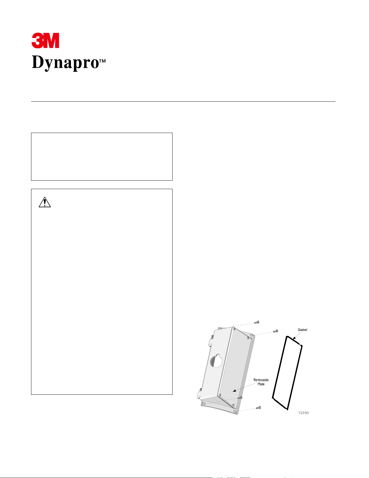
The boom mount kit includes:
! 1 hatch with boom mount opening, removable
plate and extended hatch cover (extended hatch
cover not shown in illustration below)
! 1 sealing gasket for hatch
Installing the Boom Mount 3M Dynapro ET 350 Monitor (ET 350R)
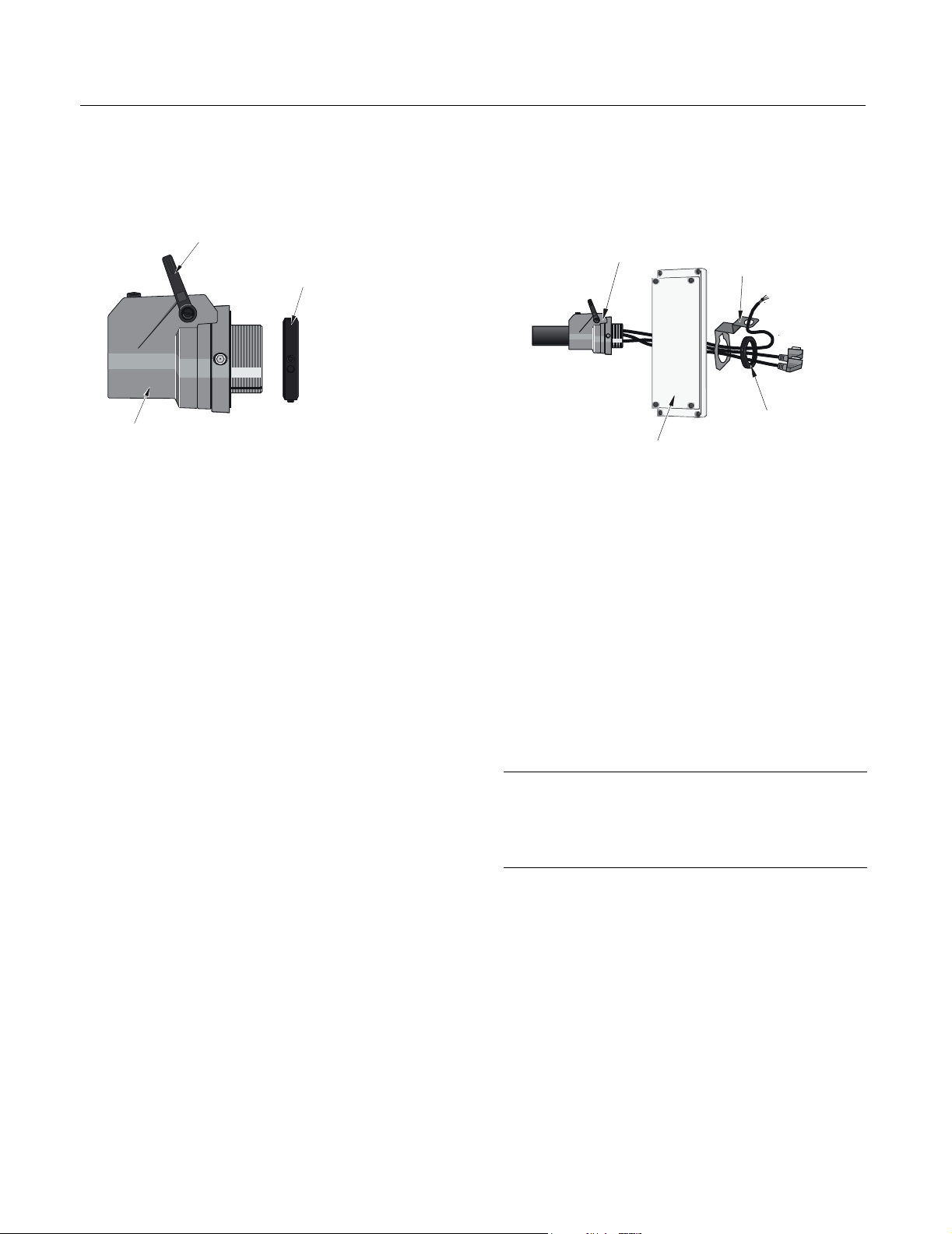
! 1 metal suspension arm coupling with tightening
ring (attached) and locking ring.
Tightening handle
Locking ring
Coupling
! 4 #6-32 x ¼ inch Phillips sealing lock screws
72042
(panhead)
! 1 conduit termination bracket (including #6-32 by
¼ inch grounding screw with captive washer
Tools required
! Phillips No. 2 screwdriver
! 9/32-inch (6 mm) Allen key
! 3/32-inch (2 mm) Allen key
Assembling the components
1. Using a 9/32-inch (6 mm) Allen key, attach the
suspension arm coupling to the boom.
2. Feed the necessary data cables through the boom
so the connectors are accessible at the ET unit’s
end.
3. Feed the cable through the boom mount so the
far end is available for connection to the power
source, and the near end is available for
connection to the power receptacle on the back
of the ET unit.
4. Fit the hatch to the suspension arm coupling,
feeding the cables through the hole in the hatch.
Coupling
Hatch cover
5. Install the conduit termination bracket, if
Conduit
termination
bracket
Locking ring
73147b
required.
6. Screw the locking ring over the threaded end of
the suspension coupling until it is tight against
the coupling and holds the hatch in an upright
position, with the hinge pins pointing upward.
7. Using a 3/32-inch (2 mm) Allen key, tighten the
set screws on the edge of the locking ring to
fasten the locking ring securely in place.
Attaching the gasket
Important
If you ordered your unit with a hatch, this gasket was
fitted at the factory. Proceed to “Mounting the unit‚” on
page 3.
1. Place the monitor face down on a horizontal
work surface (covered with foam pads or other
material to protect the monitor’s bezel and touch
screen), with the access hatch facing you.
2. Before removing the gasket backing, position the
gasket over the recessed edge of the access hatch
opening so that you know which way it fits.
13909 (Rev. 1.1) Page 2
 Loading...