

Page 1
Installing the NEMA 4X Hatch
ET 350 Monitor (Models ET 350R and ET 350L3)
Intended Use
When properly installed using the materials provided, and
according to these instructions, the NEMA 4X Hatch is
intended to provide for the ET 350 monitor (specifically,
ET 350R and ET 350L3 monitors) a NEMA 4X/IP66 seal
on all sides. The ET 350L3 monitor is also UL listed for use
in Pollution Degree 3 environments
Warning
Read and understand all safety information
before installing and using this product.
To reduce the risk of electric shock or fire which
could result in serious personal injury or death:
! Follow all product and accessory installation
instructions.
! Wiring installation should be done by a journeyman
electrician and must comply with federal and local
electrical codes.
! Any servicing or other procedures not described in this
document are to be performed only by 3M Touch
Systems service personnel.
! Properly install the monitor with a NEMA 4X gasket that
is undamaged and effective.
! Properly install the NEMA 4X gasket to achieve a
NEMA 4X/IP66 seal.
! After making an opening, make sure that there are no
metal shavings in the hatch.
! Choose fittings and a power cable that provide
adequate strain relief for communications and power
cables.
! A cable/fitting combination will have to be found that
meets local electrical requirements and the
requirements for a NEMA 4X seal.
! When connecting power with fixed field wiring for the
ET 350L3 monitor and the ET 350R monitor, the power
cable must be double insulated. A clear, flexible
insulator (supplied) must cover the portion of the cable
that is not double insulated when connecting to a
terminal strip connector..
Caution
To reduce the risk of electric shock or fire which
may result in minor or moderate injury or cause
property damage:
! Use round cables that fit the diameter range of the
cable fitting, as shown in Table A, to meet local
electrical requirements and the requirements for a
NEMA 4X/IP66 seal.
Equipment
Materials supplied
The following materials are provided for installing
the NEMA 4X hatch on the ET 350 monitor:
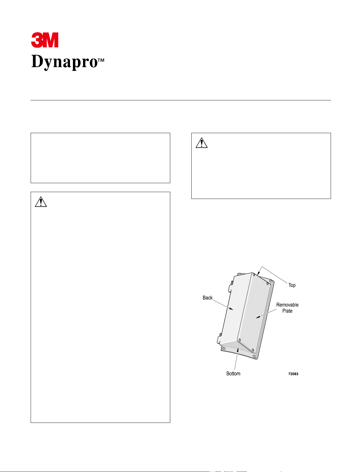
! 1 NEMA 4X hatch (with removable plate
attached
Page 2
Installing the NEMA 4X Hatch 3M Dynapro ET 350 Monitor (Models ET 350R and ET 350L3)
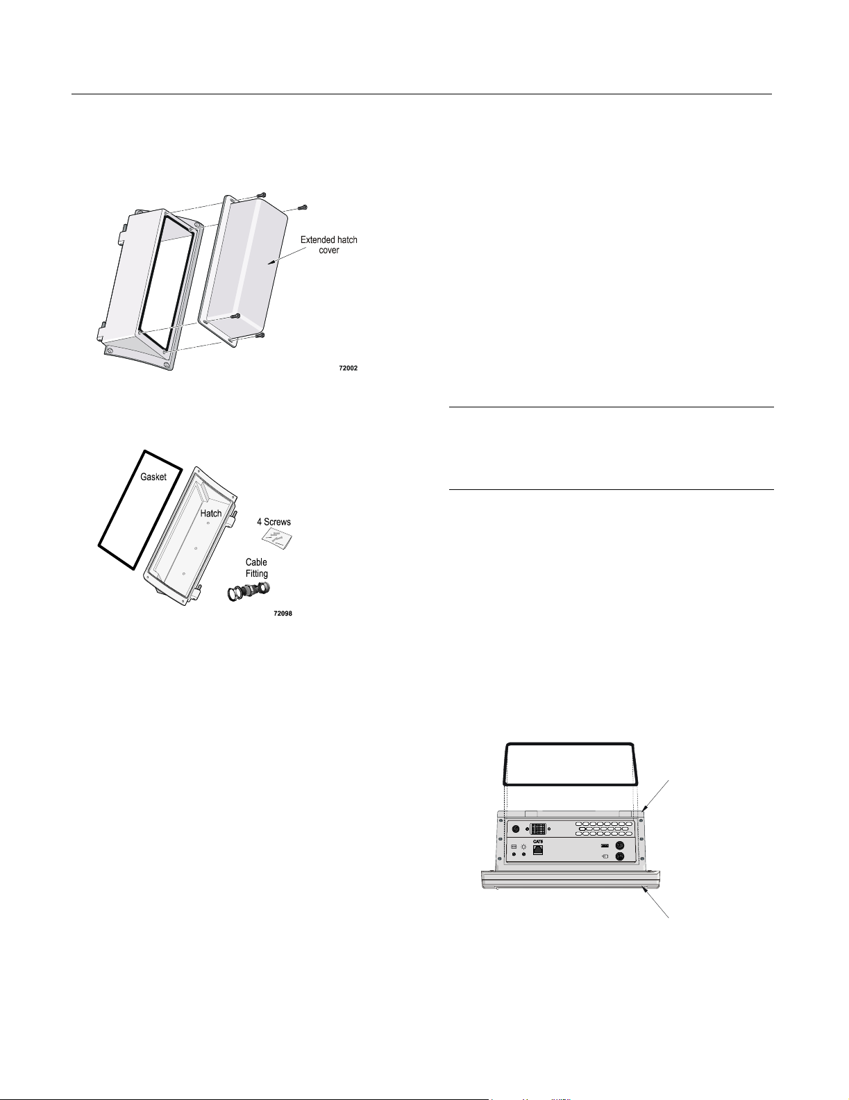
! 1 NEMA 4X extended hatch cover
! 1 gasket
! 4 #6-32 Phillips screws
Tools required
To install the NEMA 4X hatch, you will need the
following:
! Horizontal work surface with a padded cover or
foam pads to protect the front bezel and the
display of the unit.
! Flat blade screwdriver with 3/16-inch blade
! No. 1 Phillips torque screwdriver
! 1 19/32" (15 mm) open-end wrench
! 1 15/16" (24 mm) open-end wrench
Attaching the gasket
Important
If you ordered the ET 350L3 monitor, the hatch gasket
was attached at the factory. Proceed to “Preparing the
hatch for cables”.
1. Place the monitor face down on a horizontal
work surface (covered with foam pads or other
material to protect the monitor’s bezel and touch
screen), with the access hatch facing you.
! Cable fitting components (3 large sizes and
3 small sizes of each component are provided):
! Locking nut
! O-ring
! Body hex with compression sleeve
! Sealing nut
For details about the supplied cable fitting
components, see Table A.
2. Before removing the gasket backing, position the
gasket over the recessed edge of the access hatch
opening so that you know which way it fits.
Note. The gasket is not rectangular. The side of
the gasket that is placed near the back of the
monitor is shorter than the side that is placed
near the front of the monitor.
Back of monitor
Front of monitor
32525_co
19504 (Rev. 1.1) Page 2
Page 3

Installing the NEMA 4X Hatch 3M Dynapro ET 350 Monitor (Models ET 350R and ET 350L3)
3. Start at one corner and peel away just enough of
the backing to expose about 1 inch of adhesive
on each side of the corner.
Important
! The adhesive under the backing is very delicate. To
be sure that you do not remove the adhesive with the
backing, use a razor knife to separate the backing
from the adhesive.
! Do not remove the entire backing at once. Start at
one corner, lift and peel back some of the backing
only, as described below.
! Do not stretch the gasket. This can cause the
adhesive layer to come away from the gasket.
4. Place the gasket on the recessed edge of the
access hatch, with the backing side down. Line it
up with the edge of the opening in the access
hatch, then gently press the corner with the
exposed adhesive into place. Don’t press it down
firmly, yet.
5. With the gasket gently adhering at the corner,
peel the backing away from the corner carefully,
a little bit at a time, gently pressing the gasket
into place around the edge of the access hatch as
you go along. Don’t press it down firmly, yet.
6. Continue until you have removed all of the
backing and the gasket is lightly tacked into
place around the opening of the access hatch.
7. Make sure that the entire surface of the gasket is
in contact with the recessed edge of the access
hatch, without bumps or ripples.
8. When you are satisfied with the fit, use your
fingers to press the gasket firmly into place all
around the opening of the access hatch.
Preparing the hatch for cables
You can make up to four openings through the back
of the hatch.
Do not make openings in the removable plate, the top
or bottom of the hatch, nor in the extended hatch
cover (if you are using the extended hatch cover).
Important
Be sure that the openings you make are free of burrs and
that the surface around the hole is smooth and free of
debris. This will help ensure that the installed fittings seal
properly.
If you want to make your own cables, refer to pin-outs
in the 3M Dynapro ET 350 Monitor User’s
Installation Guide.
Connecting cables to the hatch
To ensure safe, certifiable connections and a complete
seal using one of the sealed fittings provided
(Table A), follow the steps in this section.
Table A: Supplied cable fittings (large and small)
Small fitting Large fitting
Manufacturer Sealcon Sealcon
Part number CD07CA-BK CD13NA-BK
Round cable
diameter range
Clearance hole
(+0.010" / -0.000")
(+0.25 mm / -
0.000 mm)
Description Straight Straight
0.150 - 0.250"
(3.81 - 6.35 mm)
0.490"
(12.5 mm)
0.250" - 0.450"
(6.35 - 11.43 mm)
0.830"
(21.1 mm)
Open-end
wrench
Torque of
locking nut
Torque of
sealing nut
19/32"
(15 mm)
20 inch-pounds 31 inch-pounds
14 inch-pounds 22 inch-pounds
15/16"
(24 mm)
19504 (Rev. 1.1) Page 3
Page 4

Installing the NEMA 4X Hatch 3M Dynapro ET 350 Monitor (Models ET 350R and ET 350L3)
Connecting supplied sealed fittings
1. Make clearance hole. Clearance hole can be
made anywhere on the back of the hatch, as long
as the hatch can open and close freely on its
hinges after the cables and/or cable fittings are
installed.
The number of holes needed will depend on
whether your ET 350 has a KVM extender
(maximum of four holes) or not (three holes).
Table B shows the clearance holes required in
each case
Note: There are three indentations on the back of
the hatch that may be used as a guide when
creating holes. However, these are only guides; if
you need four holes, you will need to decide how
best to space them.
Table B: Cable clearance holes required for ET 350
units without and with KVM extender
Opening
for this
cable
Power
Serial
ET 350 monitor
without
KVM extender
ET 350 monitor
with
KVM extender
!!
!
2. The cable fitting comes loosely assembled.
Disassemble the cable fitting into its four
components: locking nut, o-ring, body hex
(which encloses the compression sleeve), and
sealing nut.
3. Install the o-ring onto the surface of the body hex
and then insert the body hex (with o-ring
attached) into the clearance hole on the outside
of the hatch.
4. On the inside of the hatch, attach the locking nut
to the body hex.
VGA
!
5. Holding the body hex stationary with a wrench,
hand-tighten the locking nut and then use a
CAT5
!
second wrench to tighten the locking nut until the
cable fitting is held in place securely (see
Mouse
Keyboard
!
!
Table A for suggested torque values).
6. Slide the sealing nut onto the cable and then,
from the outside of the hatch, feed the cable
through the cable fitting.
Important
If the diameter of the cable is close to the ranges of both
the small and large fittings shown in Table A, try running
the cable through the smaller fitting before beginning to
connect the fittings. If the cable will go through the small
fitting without being forced, 3M Touch Systems
recommends using that fitting.
7. Gently screw the sealing nut onto the body hex,
but do not tighten it. Leave the sealing nut loose
to allow the cable to move through the fitting.
8. Slide the cable through the body hex and into the
hatch until you are satisfied with the amount of
cable inside and outside of the hatch.
Make sure there is enough slack in the cable to
allow the hatch to fully open and close on its
hinges without straining the cables or connectors.
19504 (Rev. 1.1) Page 4
Page 5

Installing the NEMA 4X Hatch 3M Dynapro ET 350 Monitor (Models ET 350R and ET 350L3)
9. Holding the body hex stationary with a wrench,
hand-tighten the sealing nut and then use a
second wrench to tighten the sealing nut until the
wire is held securely in place (see Table A for
suggested torque values).
10. Using a wrench on the body hex, make sure that
the cable fitting still is tightly screwed into the
hatch.
11. Insert the hinge pins of the hatch into the hinges
of the ET 350, close the hatch and make sure that
the screw holes in the edges of the hatch line up
with the threaded holes in the ET 350 monitor
enclosure.
Important
If you need to examine cables inside the access hatch,
take off the removable plate (or extended hatch cover)
from the hatch.
Closing the hatch
To close the hatch, follow these steps:
Replacing cables
To replace a cable, disassemble the fitting by
following these steps:
1. Using a wrench to hold the body hex stationary,
loosen the sealing nut with a second wrench.
2. Grip the disconnected cable and pull while
turning the cable in a counter-clockwise
direction.
The new cable you install will require a new fitting.
1. Attach cables to their respective connectors.
2. Close and fasten the hatch by loosely attaching
the four #6-32 Phillips screws.
3. Using a No. 1 Phillips torque screwdriver,
gradually tighten diagonal pairs until all the
screws are equally tight at a torque of 7 inchpounds. This may require about three rounds of
tightening.
19504 (Rev. 1.1) Page 5
Page 6

Copyright
This manual is © 3M 2002. All rights reserved.
Reproduction of the contents of this copyrighted manual in
whole or in part, by any means, electronic or mechanical,
for any purpose, without written permission of 3M Touch
Systems, a subsidiary of 3M, is prohibited.
Notice
Given the variety of factors that can affect the use and
performance of a 3M Touch Systems Product, including
that solid state equipment has operation characteristics
different from electromechanical equipment, some of
which factors are uniquely within User's knowledge and
control, it is essential that User evaluate the 3M Touch
Systems product to determine whether it is suitable for
User’s particular purpose and suitable for User’s method of
application. 3M Touch Systems’ statements,
engineering/technical information, and recommendations
are provided for User’s convenience, but their accuracy or
completeness is not warranted. 3M Touch Systems
products are not specifically designed for use in medical
devices as defined by United States federal law. 3M Touch
Systems products should not be used in such applications
without 3M Touch Systems’ express written consent. User
should contact its sales representative if User’s opportunity
involves a medical device application.
Important notice to purchaser
Specifications are subject to change without notice. 3M
Touch Systems’ Products are warranted to meet their
published specifications from the date of shipment and for
the period stated in the specification. 3M Touch Systems
makes no additional warranties, express or implied,
including but not limited to any implied warranties of
merchantability or fitness for a particular purpose.
User is responsible for determining whether the 3M Touch
Systems Products are fit for User’s particular purpose and
suitable for its method of production, including intellectual
property liability for User's application. If a Product is
proven not to have met 3M Touch Systems’ warranty, then
3M Touch Systems’ sole obligation and User’s and
Purchaser’s exclusive remedy, will be, at 3M Touch
Systems’ option, to repair or replace that Product quantity
or to refund its purchase price. 3M Touch Systems has no
obligation under 3M Touch Systems’ warranty for any
Product that has been modified or damaged through
misuse, accident, neglect, or subsequent manufacturing
operations or assemblies by anyone other than 3M Touch
Systems. 3M Touch Systems shall not be liable in any
action against it in any way related to the Products for
any loss or damages, whether non-specified direct,
indirect, special, incidental or consequential (including
downtime, loss of profits or goodwill) regardless of the
legal theory asserted.
(11/01)
Edition
Second edition: January 2002
Document Number: 19504 (Rev. 1.1)
Trademark
3M Dynapro is a trademark of 3M.
Page 7

3M Touch Systems
3M Optical Systems Division
800 Carleton Court
Annacis Island
New Westminster, BC
Canada V3M 6L3
www.3Mtouch.com
Worldwide Manufacturing Plants
Austin, Texas
Methuen, Massachusetts
Milwaukee, Wisconsin
Vancouver, BC, Canada
Abingdon, UK
For more information on 3M touch products, visit
3Mtouch.com or call toll-free 1-800-667-0374.
© 3M 2002
19504 (Rev. 1.1)
 Loading...