

Page 1
Replacing backlights
ET 3255 Computer HL (Hazardous Locations)
Intended Use
When properly installed using the materials provided, and
according to these instructions, this Backlight
Replacement Kit is intended to allow backlights for the
ET 3255 Computer HL to be replaced.
Warning
Read and understand all safety information in the
ET 3200 Series Computer User’s Guide and in this
document before installing and using the ET 3255
computer.
If there appears to be a conflict between information in the
ET 3200 Series Computer User’s Guide and this
document, this document takes precedence.
Warning
TO REDUCE THE RISK OF FIRE OR ELECTRIC SHOCK WHICH
COULD RESULT IN SERIOUS PERSONAL INJURY OR DEATH:
! This repair should be performed only by trained
personnel. Failure to perform all operations correctly
could damage the unit and invalidate the warranty.
! To ensure compliance with electrical codes and safe
operation of the computer, removal and re-installation of
the computer should be performed by a licensed
journeyman electrician who is familiar with local codes.
! Any servicing or other procedures not described in this
document are to be performed only by 3M Touch
Systems personnel.
Warning
TO REDUCE THE RISK OF FIRE OR ELECTRIC SHOCK WHICH
COULD RESULT IN SERIOUS PERSONAL INJURY OR DEATH:
! If the computer is in a hazardous location, it should be
removed to a non-hazardous location in a facility
suitable for repairing electronics. Before disconnecting
power and other connections and removing the unit from
its mounting, make sure that the area is free of
hazardous gases.
! Before removing the computer from its mounting,
disconnect power to the unit.
! When replacing the backlights, use the ones included
with these instructions in the Backlight Replacement Kit.
! Properly install the computer ensuring that all NEMA 4X
gaskets are clean, undamaged, and effective.
! When closing the hatch of the computer, make sure that
it closes flush and that the hatch screws do not bind
when they are attached. If the hatch is not closed
properly, the NEMA 4X seal may be compromised and
the warranty voided.
! Take care not to pinch backlight inverter wires when
reassembling and reinstalling the display plan or when
closing the computer
! Do not pull on or repeatedly bend lead wires. The wires
could break, causing backlight failure.
! Do not solder backlight leads. A thermal shock may
cause the glass part to crack and the backlight to fail.
! Do not substitute, lengthen, or cut the CCFL lead wires
on the backlights. Due to the high voltage applied at the
ends of the wires, the leads are made of high voltageresistant material.
Warning
TO REDUCE THE RISK OF FIRE OR EXPLOSION WHICH COULD
RESULT IN SERIOUS PERSONAL INJURY OR DEATH, do not use
cleaners that are flammable or combustible.
Page 2
Replacing backlights ET 3255 Computer HL (Hazardous Locations)
Equipment
Caution
TO REDUCE THE RISK OF MINOR OR MODERATE INJURY FROM
CONTACT WITH CLEANING SOLUTIONS OR FLUIDS THROUGH
MEANS SUCH AS INJESTION AND SKIN CONTACT:
! Do not touch the inner surface of a damaged backlight
with bare skin. If bare skin does come in contact with the
inner surface of a backlight, immediately wash with soap
and water. There is a small amount of mercury inside
the backlights.
! Before using a cleaner, refer to the cleaner
manufacturer’s material safety data sheet and follow all
instructions and recommendations.
Caution
TO REDUCE THE RISK OF ENVIRONMENTAL CONTAMINATION
WHICH MAY RESULT IN MINOR OR MODERATE INJURY OR
CAUSE PROPERTY DAMAGE:
! Old backlights must be disposed of in accordance with
local municipal and governmental ordinances, laws, and
regulations.
! Protect backlights from strong shock or other forces that
could cause them to break. A broken backlight has the
potential for injury and should be handled with care.
! Do not look directly at a lit backlight at close proximity
and do not work for many hours exposing your eyes to
direct output from backlights. Disregarding this caution
could result in eye injury.
Caution
TO REDUCE THE RISK OF FIRE OR SMOKE, do not let paper,
cloth, or other flammable materials come in contact with
a backlight.
Materials supplied in the kit
The backlight replacement kit contains:
! 1 upper backlight
! 1 lower backlight
! 1 5/32-inch (4 mm) Allen key
! 1 grounding wrist strap
Materials and tools required
! 5/32-inch (4 mm) Allen key (supplied) or
1/4-inch flat-blade screwdriver to open the
computer
! 5/16-inch torque hex nut driver
! No. 1 Phillips torque screwdriver
! Security screwdriver, if the enclosure is secured
with security screws. A security screwdriver
option is available from 3M Touch Systems or
from your local hardware retailer.
! Cleaner and cloths designed for cleaning coated
optical glass that are neither flammable nor
combustible.
! 1 grounding strap (for assistant)
Personnel and facilities required
To complete this procedure you will need:
! Two people (each wearing a grounding strap).
! A clean, ESD-protected environment with a work
surface covered with foam pads or other suitable
material to protect the touch screen and bezel.
20008 (Rev.1.0) Page 2
Page 3
Replacing backlights ET 3255 Computer HL (Hazardous Locations)
Replacing the backlights: Steps
The Backlight Replacement kit for the ET 3255
Computer HL contains two backlights: one for the top
of the display and one for the bottom. The top and
bottom backlights are not interchangeable. 3M Touch
Systems recommends replacing both backlights at the
same time.
1. Put on a grounding strap, connect to ground, and
touch a grounded object to discharge any builtup static.
Important
To prevent damage from electrostatic discharge (ESD),
wear a grounding wrist strap when working with electronic
components inside the enclosure. Follow the instructions
that come with the wrist strap.
Warning
TO REDUCE THE RISK OF FIRE OR ELECTRIC SHOCK WHICH
COULD RESULT IN SERIOUS PERSONAL INJURY OR DEATH, if
the computer is in a hazardous location, it should be
removed to a non-hazardous location that is suitable for
repairing electronics. Before disconnecting power and
other connections and removing the unit from its
mounting, make sure that the area is free of hazardous
gases.
5. To protect the touch screen and bezel, place the
unit in an ESD-protected environment and on a
work surface covered with ESD-dissipative foam
pads or other ESD-dissipative material.
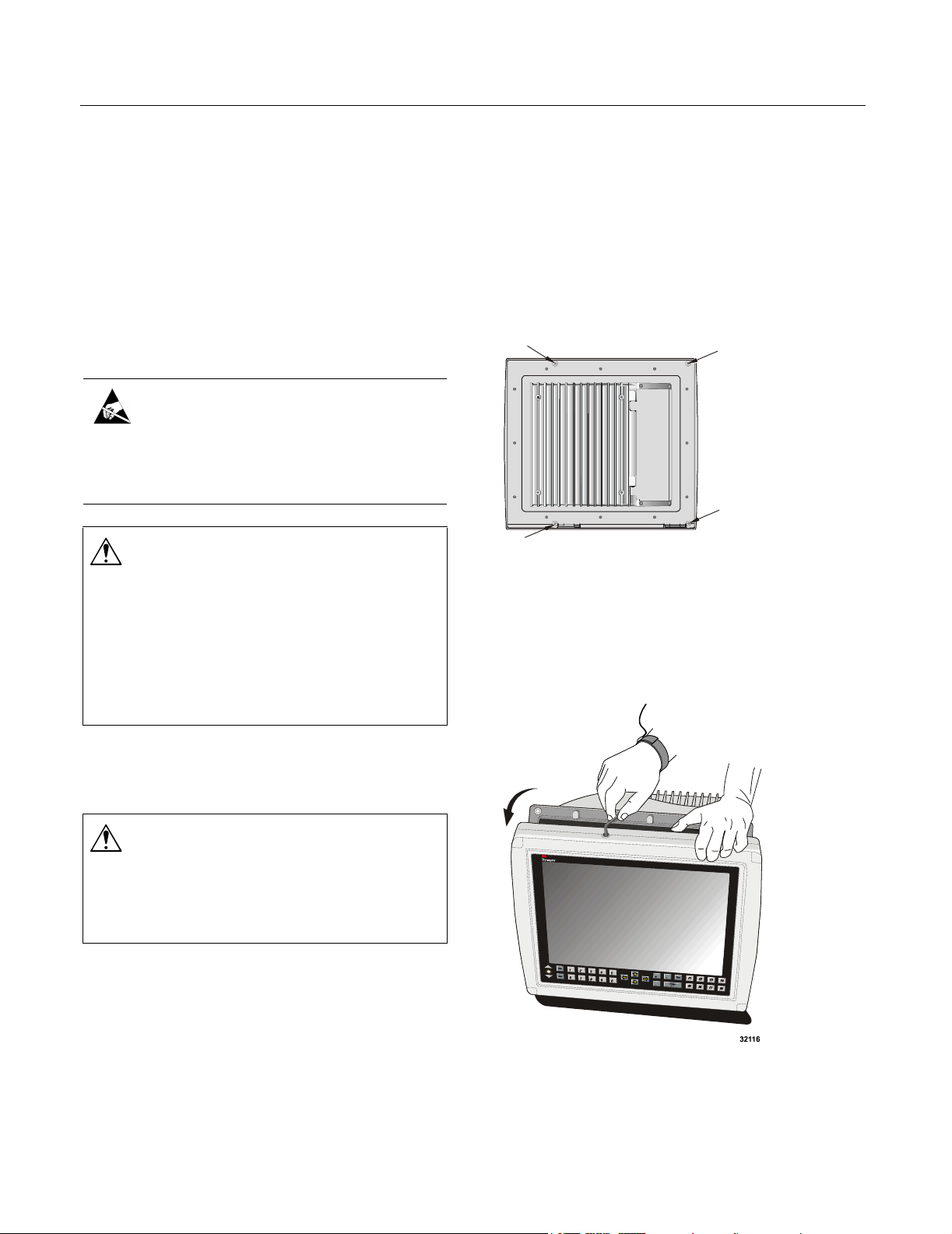
6. See if there are security screws at the four
corners of the back of the bezel and, if there are,
remove them with a security screwdriver (for
information on getting a security screwdriver,
see “Materials and tools required”).
Security
Screws (4)
Figure 1: Locations of security screws (security
screws are not attached to all units)
7. To unlock the bezel assembly, find the latch
screw on the top of the enclosure and use the
Allen key or a flat-blade screwdriver to turn the
latch screw ¼ turn counter-clockwise, or until
you feel the enclosure open (Figure 2).
2. Make sure the area is free of hazardous gases and
then disconnect the power supply to the unit.
Warning
TO REDUCE THE RISK OF ELECTRIC SHOCK WHICH COULD
RESULT IN SERIOUS PERSONAL INJURY OR DEATH, before
removing the computer from its mounting, disconnect
power to the unit.
3. Disconnect all communication cables from the
unit.
4. Remove the unit from its mounting and, if the
computer is in a hazardous location, move it to a
non-hazardous location.
20008 (Rev.1.0) Page 3
Figure 2: Opening the computer enclosure
Page 4
Replacing backlights ET 3255 Computer HL (Hazardous Locations)
8. Place the computer face down on the work bench
and open the main enclosure as far as it will go.
9. Have another person assist you by supporting the
enclosure in the open position so that it does not
tip over. Make sure that your assistant is also
wearing a grounding strap.
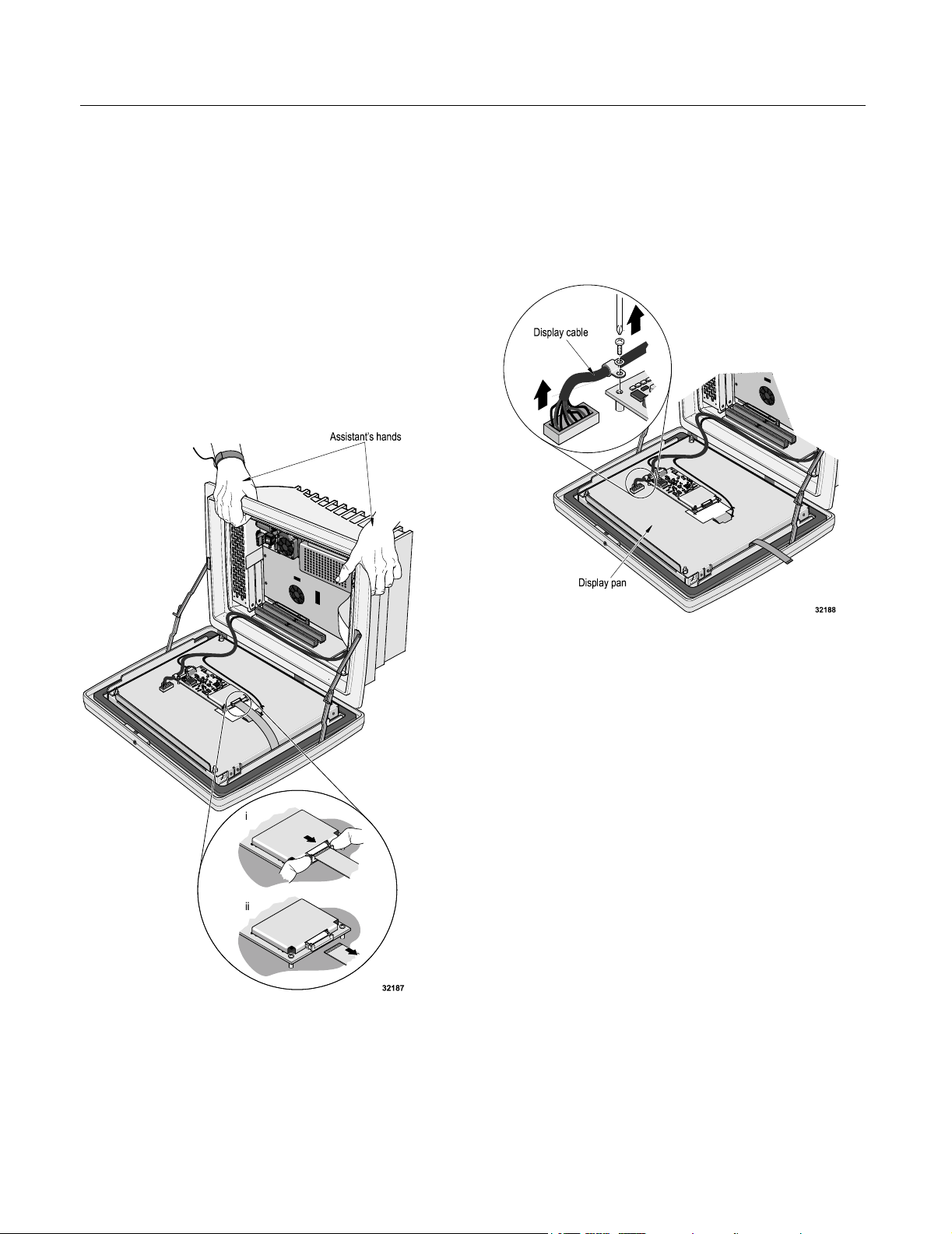
10. Carefully disconnect the touch screen tail
(Figure 3):
i. Using two fingers, gently pull the connector
tab towards you until it stops.
ii. Carefully pull the touch screen tail from the
connector.
11. Using a No.1 Phillips screwdriver, remove the
screw and washer from the clamp that holds the
display cable to the touch screen controller
(Figure 4).
12. Carefully disconnect the display cable connector
from the socket on the back of the display pan.
Figure 3: Disconnecting the touch screen tail
Figure 4: Disconnecting the display cable connector
13. Loosen the four nuts that secure the display pan,
and remove them. Notice that the two nuts on the
hinge side of the pan do not have washers. The
nuts on the opposite side have flat washers
(Figure 5).
20008 (Rev.1.0) Page 4
Page 5

Replacing backlights ET 3255 Computer HL (Hazardous Locations)
Figure 5: Removing the display pan nuts
14. Carefully slide the display pan away from the
threaded studs and lift it to a vertical position,
taking care not to damage the cable that connects
it to the computer (Figure 6):
i. Lift the hinge side of the display pan up from
the threaded studs.
ii. Slide the display pan away from the other
two threaded studs.
Figure 6: Sliding the display pan out and lifting it.
Important
When you lift the display pan, you expose the display and
the interior side of the glass touch screen.
The surface of the display and the glass surface of the
touch screen mark easily. Do not touch or scratch these
surfaces while replacing the backlights. If you do touch
them and leave stains or fingerprints, clean them before
you close the enclosure. See Step 25 on page 8.
iii. Lift the display pan to a vertical position and
have your assistant support both the display
and the main enclosure.
15. Unscrew the display from the display pan, using
a No. 1 Phillips screwdriver, as follows
(Figure 7):
i. First, remove the two screws on the right
side of the display.
ii. Then remove the four screws on the left side
of the display.
20008 (Rev.1.0) Page 5
Page 6

Replacing backlights ET 3255 Computer HL (Hazardous Locations)
Figure 7: Unscrewing the display from the display pan
16. Carefully lift the display from the display pan,
taking care not to damage the backlight
connector wires that still connect it to the display
pan.
17. Under the display, you will see wires running
from the backlights to the backlight inverter on
the display pan. Disconnect the backlight
connectors from the backlight inverter
(Figure 8 and Figure 9).
Important
Pay attention to the orientation of the connectors as you
remove them so that later you can reinsert them correctly.
Figure 8: Disconnecting the backlight connectors
Figure 9: Backlight connector fully connected and
disconnected
18. Remove the display from the display pan and set
the display on a clean, protected work surface
with the display side down.
20008 (Rev.1.0) Page 6
Page 7

Replacing backlights ET 3255 Computer HL (Hazardous Locations)
19. On the display, you will see wires that are
attached to each of the backlights. Each backlight
is inserted into a white plastic retaining channel.
The backlights are held in place with small, darkcolored Phillips-head retaining screws.
To remove a backlight:
i. Remove the screw using a No. 1 Phillips
screwdriver (Figure 10).
ii. Using your fingers, gently pull out the
Important
! When handling a backlight, avoid touching the bulb
with bare fingers. Oil from fingers will leave a deposit
on the glass that will decrease the life span of the bulb.
! Before inserting the new backlights, note that there is
an upper backlight (labelled
(labelled
backlight. Make sure you insert the correct backlight
into each retaining channel.
“Low”). The label is on the underside of the
“Up”), and a lower one
backlight (Figure 11).
Notice that the glass tube inside the backlight
is facing the edge of the display, and that
there is only one way for the backlight to fit
in the retaining channel.
iii. Remove the other backlight.
Figure 10: Removing the screw that holds the
backlight (upper backlight, in this illustration)
.
20. Insert the new backlights into the retaining
channels, sliding them in until the holes for the
backlight retaining screws line up. Note that the
backlights are not interchangeable. The backlight
labelled “Up” is the top backlight; the one
labelled “Low” is the bottom backlight.
The label is located on the side of the backlight
that faces down as you slide it into the retaining
channel (Figure 11).
21. Attach the backlights to the display frame with
the small Phillips-head retaining screws that
were removed in Step 19. Hand tighten the
screws.
Important
Do not overtighten the screws, or you will strip the
threads in the plastic backlight.
22. Re-position the display on the display pan and
re-attach the backlight wire connectors to the
backlight inverter on the display pan (Figure 9 on
page 6 and Figure 12).
Important
There is only one way to insert the backlight connector.
Do not force the connector if it does not fit.
Backlight label
"UP" or "LOW"
(underneath
backlight)
Figure 11: Removing the backlight (upper backlight in
this illustration)
20008 (Rev.1.0) Page 7
Page 8

Replacing backlights ET 3255 Computer HL (Hazardous Locations)
24. Attach the display frame to the display pan (see
Figure 7 on page 6):
i. First attach the four screws on the left side of
the display.
ii. Then attach the two screws on the right side
of the display.
iii. Tighten the screws to a torque of 5 inch-
pounds.
25. The back of the MicroTouch
Imaging
TM
(NFI) touch screen (the surface that
TM
Near Field
faces the inside of the computer) may have a
special anti-reflective coating that can be
damaged by commercial glass cleaners and
cloths. To clean this surface, use a noncombustible, non-flammable cleaner designed
for cleaning coated glass.
26. Lower the display pan to its original position and
secure it with the nuts that were removed in
Step 13. Make sure you use the washers with the
threaded studs on the side of the display pan
farther from the hinges (see Figure 5 on page 5).
Figure 12: Connecting the new backlights
Tighten the nuts to a torque of 10 inch-pounds.
23. Bend the backlight wires so that they are out of
the way and will not be pinched when you
reassemble and reinstall the display pan and
close the computer.
27. Reconnect the display cable to the connector on
the back of the display pan (see Figure 4 on
page 4).
28. Using a Phillips-head screwdriver, re-attach the
cable and cable clamp to the controller to a
Warning
torque of 5 inch-pounds (refer to Figure 4 on
page 4).
To reduce the risk of fire or electric shock which could
result in serious personal injury or death, take care not to
pinch backlight inverter wires when reassembling and
reinstalling the display plan or when closing the computer.
20008 (Rev.1.0) Page 8
Page 9

Replacing backlights ET 3255 Computer HL (Hazardous Locations)
29. Reconnect the touch screen tail to the controller
(Figure 13):
i. Use two fingers to carefully pull the
connector tab towards you until it stops.
ii. Gently insert the touch screen tail into the
connector.
iii. Press the connector tab back into place.
30. Check the connectors to make sure they are
properly seated and that cables are not damaged.
31. Close the bezel assembly and lock it by inserting
the Allen key (or a flat-blade screwdriver) in the
latch screw on the top of the enclosure, making
sure that the latch screw engages the housing pin.
Turn the latch screw ¼ turn clockwise or until it
stops. If the bezel assembly was secured with
security screws, re-install them now.
Warning
When closing the hatch of the computer, make sure that
it closes flush and that the hatch screws do not bind when
they are attached. If the hatch is not closed properly, the
NEMA 4X seal may be compromised and the warranty
voided.
32. If the front surface of the touch screen needs
cleaning, use a non-combustible, non-flammable
cleaner that will not corrode glass.
33. Power up the computer, check that the LCD
display is operating and, if so, disconnect power
again.
Figure 13: Reconnecting the touch screen tail
34. Before returning the computer to its hazardous
location, make sure that the hazardous location is
free of hazardous gases.
35. Return the computer to its hazardous location
and re-install it in its mounting device.
36. Connect power to the computer and check again
that the LCD display is operating.
Troubleshooting
If the display does not function properly:
1. Remove the computer to a non-hazardous
location.
2. Open the computer and make sure that all the
connectors are properly seated and that no wires
or cables were damaged during re-assembly of
the computer.
3. If the display still does not function properly,
contact 3M Touch Systems technical support
(see “Contacting 3M Touch Systems”).
20008 (Rev.1.0) Page 9
Page 10

Replacing backlights ET 3255 Computer HL (Hazardous Locations)
Contacting 3M Touch Systems
For general information, service, and technical
support for 3M Dynapro products, use the contact
information below:
Area Type of
service
USA
and
Canada
Outside
USA
and
Canada
General
information
Customer
service
Technical
support
General
information
Contact information
Tel 800-667-0374 (toll free)*
Fax 604-521-4629
E-mail etsales@mmm.com
Web site www.3Mtouch.com
Tel 800-667-0374 (toll free)*
Fax 604-521-4629
E-mail
3MTScustomerservice@mmm
.com
Tel 800-667-0374 (toll free)*
Fax 604-521-4629
E-mail
3Mdynaprotechsupport@mmm
.com
Tel 604-521-3962*
Fax 604-521-4629
E-mail etsales@mmm.com
Customer
service
Technical
support
*Call between 7:30 a.m. and 5:00 p.m., Pacific Time
20008 (Rev.1.0) Page 10
Tel 800-667-0374*
Fax 604-521-4629
E-mail
3MTScustomerservice@mmm
.com
Tel 604-521-3962*
Fax 604-521-4629
E-mail
3Mdynaprotechsupport@mmm
.com
Page 11

Replacing backlights ET 3255 Computer HL (Hazardous Locations)
Copyright
This manual is © 3M 2002. All rights reserved.
Reproduction of the contents of this copyrighted manual in
whole or in part, by any means, electronic or mechanical,
for any purpose, without written permission of 3M Touch
Systems, a subsidiary of 3M, is prohibited.
Notice
Given the variety of factors that can affect the use and
performance of a 3M Touch Systems Product, including
that solid state equipment has operation characteristics
different from electromechanical equipment, some of
which factors are uniquely within User's knowledge and
control, it is essential that User evaluate the 3M Touch
Systems product to determine whether it is suitable for
User’s particular purpose and suitable for User’s method of
application. 3M Touch Systems’ statements,
engineering/technical information, and recommendations
are provided for User’s convenience, but their accuracy or
completeness is not warranted. 3M Touch Systems
products are not specifically designed for use in medical
devices as defined by United States federal law. 3M Touch
Systems products should not be used in such applications
without 3M Touch Systems’ express written consent. User
should contact its sales representative if User’s opportunity
involves a medical device application.
Important notice to purchaser
Specifications are subject to change without notice. 3M
Touch Systems’ Products are warranted to meet their
published specifications from the date of shipment and for
the period stated in the specification. 3M Touch Systems
makes no additional warranties, express or implied,
including but not limited to any implied warranties of
merchantability or fitness for a particular purpose.
User is responsible for determining whether the 3M Touch
Systems Products are fit for User’s particular purpose and
suitable for its method of production, including intellectual
property liability for User's application. If a Product is
proven not to have met 3M Touch Systems’ warranty, then
3M Touch Systems’ sole obligation and User’s and
Purchaser’s exclusive remedy, will be, at 3M Touch
Systems’ option, to repair or replace that Product quantity
or to refund its purchase price. 3M Touch Systems has no
obligation under 3M Touch Systems’ warranty for any
Product that has been modified or damaged through
misuse, accident, neglect, or subsequent manufacturing
operations or assemblies by anyone other than 3M Touch
Systems. 3M Touch Systems shall not be liable in any
action against it in any way related to the Products for
any loss or damages, whether non-specified direct,
indirect, special, incidental or consequential (including
downtime, loss of profits or goodwill) regardless of the
legal theory asserted.
(11/01)
Edition
First edition: March 2002
Document Number: 20008 (Rev. 1.0)
Trademark
3M Dynapro, MicroTouch, and Near Field Imaging are
trademarks of 3M.
20008 (Rev.1.0) Page 11
Page 12

3M Touch Systems
3M Optical Systems Division
800 Carleton Court
Annacis Island
New Westminster, BC
Canada V3M 6L3
www.3Mtouch.com
Worldwide Manufacturing Plants
Austin, Texas
Methuen, Massachusetts
Milwaukee, Wisconsin
Vancouver, BC, Canada
Abingdon, UK
For more information on 3M touch products, visit
3Mtouch.com or call toll-free 1-800-667-0374.
© 3M 2002
20008 (Rev. 1.0)
 Loading...