

Installing the NEMA 4X hatch
ET 355 Monitor HL
Intended Use
When properly installed according to the instructions,
the NEMA 4X hatch is intended to provide a NEMA
TM
4X/IP66 seal on all sides for the 3M Dynapro
ET 355 Monitor HL (hereafter, ET 355 monitor).
The ET 355 monitor is a component. After the
monitor is installed with the NEMA 4X hatch, the
whole system of which it is a part must be inspected
to confirm seal ratings and compliance with all local
electrical codes.
Product safety information
Opening the unit
DANGER
TO REDUCE THE RISKS ASSOCIATED WITH FIRE AND EXPLOSION
WHICH, IF NOT AVOIDED, WILL RESULT IN DEATH OR SERIOUS INJURY
AND/OR PROPERTY DAMAGE:
! Do not open the monitor while the circuit is live unless the area
is known to be non-hazardous.
! Do not operate the monitor’s OSD switches, DIP switch, KVM
extender remote board, or potentiometer on the KVM extender
remote board unless the area is known to be non-hazardous.
Instructions and procedures
Installing and sealing
WARNING
TO REDUCE THE RISKS ASSOCIATED WITH ELECTRICAL SHOCK, FIRE
AND EXPLOSION WHICH, IF NOT AVOIDED, COULD RESULT IN DEATH
OR SERIOUS INJURY AND/OR PROPERTY DAMAGE, IF THE NEMA 4X
HATCH IS PART OF YOUR APPLICATION:
! Choose Listed (UL) conduit hubs that are rated to NEMA
4X/IP66 standards, are suitable for use in hazardous locations,
and provide adequate strain relief for wiring.
! After making an opening in the NEMA 4X hatch, make sure that
there are no metal shavings in the hatch.
! Properly install the monitor so that it is environmentally sealed
to the NEMA 4X/IP66 standard. Do not use the ET 355 monitor
with mounting options that are not rated for NEMA 4X/IP66 in
environments that require such a seal.
! Properly install the ET 355 monitor with a NEMA 4X gasket that
is clean, undamaged, and effective.
! When closing the hatch of the unit, make sure that it closes flush
and that the hatch screws do not bind when they are attached.
If the hatch is not closed properly, the NEMA 4X seal may be
compromised and the warranty voided.
Power supply, wiring methods
For product safety information about power supply
and wiring methods for the ET 355 monitor, refer to
the Installation Addendum: ET 355 Monitor. The
Installation Addendum ships with the ET 355
monitor.
WARNING
TO REDUCE THE RISKS ASSOCIATED WITH ELECTRICAL SHOCK, FIRE,
OR EXPLOSION WHICH, IF NOT AVOIDED, COULD RESULT IN DEATH OR
SERIOUS INJURY AND/OR PROPERTY DAMAGE:
! Follow all product and accessory installation instructions.
! The procedures described in this document should be performed
only by trained personnel. Failure to perform all operations
correctly could damage the unit and invalidate the warranty.
Read and understand all safety information in this document,
the ET 350 Monitor User’s Installation Guide,
and the Installation Addendum: ET 355 Monitor HL
before installing and using the NEMA 4X hatch.
Installing the NEMA 4X Hatch ET 355 Monitor HL
r
Equipment
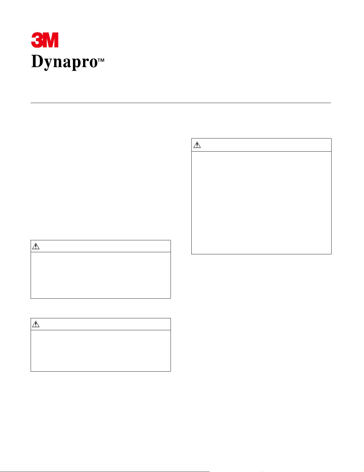
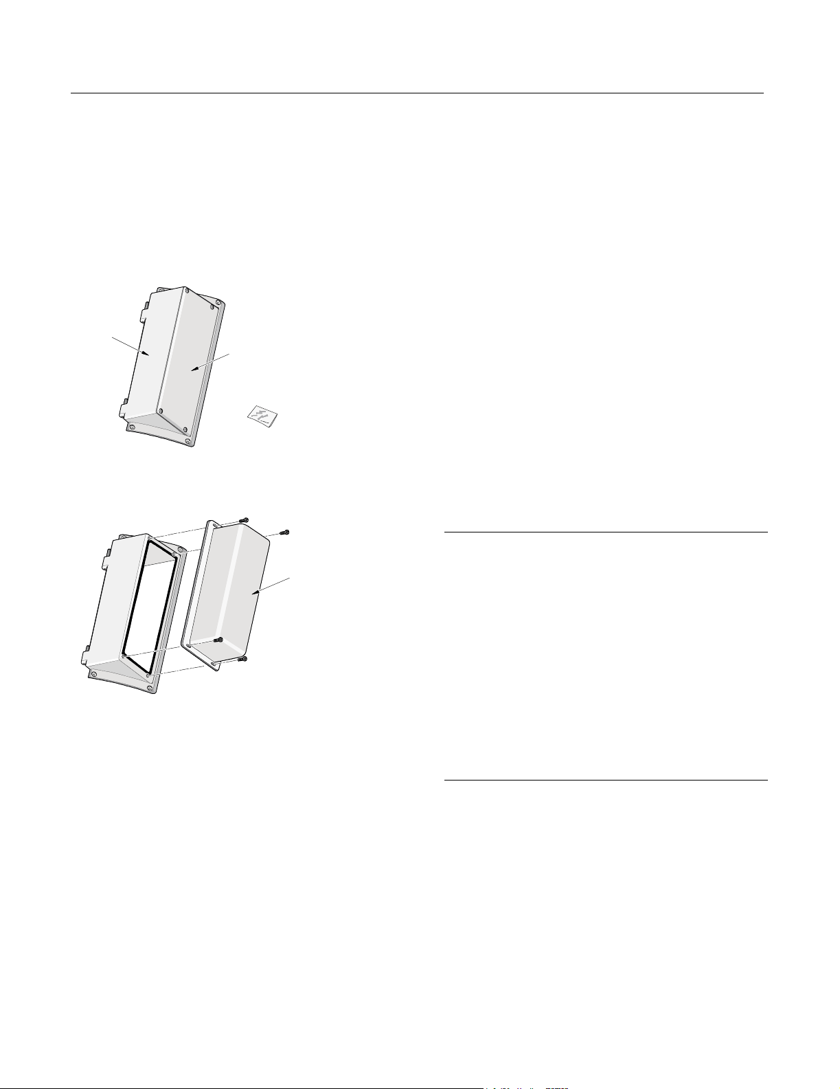
Materials supplied
The following materials are provided for installing
the NEMA 4X hatch on the ET 355 monitor:
! 1 NEMA 4X hatch (with removable plate
attached) and 4 #6-32 Phillips screws
Back
(make all
openings here)
Removable
Plate
4 screws
72083 b
! 1 NEMA 4X extended hatch cover
Extended hatch cove
72002 b
Tools and material required
You will need the following tools and material to
install the NEMA 4X hatch to the ET 355 monitor:
! No. 1 Phillips torque screwdriver
! Sealed Listed (UL) conduit hubs that meet
NEMA 4X/IP66 ratings
! A punch or drill to make openings in the hatch
Steps
To mount a NEMA 4X hatch on the ET 355 monitor,
follow these steps:
1. Decide on the number and locations of hatch
openings required for your application.
2. If the ET 355 monitor is in a hazardous location,
make sure that the location is free of hazardous
gases.
3. Disconnect power and other connections.
4. Make openings in the back of the hatch. If you
need three or fewer openings, you can use as
guides the three indentations on the back of the
hatch. If you need four openings, you will need
to decide how best to space them.
Openings can be made anywhere on the back of
the hatch, as long as the hatch can open and close
freely on its hinges after conduit hubs are
installed.
Important
! Do not make openings in the removable plate, the top, or
the bottom of the hatch, or in the extended hatch cover
(if you are using the extended hatch cover).
! Be sure that any opening you make is free of burrs and
that the surface around the hole is smooth and free of
debris. This will help ensure that the installed fittings seal
properly.
! Be sure that openings do not have sharp edges that
could damage wiring.
! Provide appropriate Listed (UL) conduit hubs that, when
installed according to the manufacturer’s instructions
and the National Electrical Code or local electrical code,
will provide a NEMA 4X/IP66 seal.
5. Attach conduit hubs through the hatch openings
and tighten them to torque settings recommended
by the manufacturer to achieve a NEMA
4X/IP66 rating.
20137 (Rev. 1.0) Page 2

Installing the NEMA 4X Hatch ET 355 Monitor HL
11. Wire all connectors and attach locking devices to
Important
! Flexible conduit allows for greater flexibility during
installation of the NEMA 4X hatch than does rigid
conduit. However, wiring methods must be in
accordance with Class I, Division 2 wiring methods
Article 501-4(b) or the National Electric Code, NFPA 70
for installations in the U.S., or as specified in Section 181J2 of the Canadian Electrical Code for installations
within Canada and in accordance with the authority
having jurisdiction.
! If you use rigid conduit, first attach the monitor to the rigid
conduit and then place the monitor in its final position.
3M Touch Systems recommends that either the monitor
be mounted close to a junction box or that a junction box
be installed close to the monitor.
! The closer the monitor is to a junction box, the easier it
is to make the final connection and mounting of rigid
conduit.
provide strain relief.
12. Close and fasten the hatch by loosely attaching
the four #6-32 Phillips screws. Check to make
sure that the screw holes in the edges of the hatch
line up with the threaded holes in the monitor
enclosure.
Important
If you need to examine wiring inside the hatch, take off the
removable plate (or extended hatch cover) from the hatch.
13. Using a No. 1 Phillips torque screwdriver,
gradually tighten diagonal pairs until all the
screws are equally tight at a torque of 7 inchpounds. This should require about three rounds
of tightening.
6. Install the monitor on its mounting so that it is
rigidly fixed.
7. Temporarily insert the hinge pins of the hatch
and fasten with the #6-32 Phillips screws
provided.
8. Bring the conduit to the hatch, aligning it with
each hub, and attach the conduit to the hub
14. While the monitor is still in a location that is free
of hazardous gases, connect power to the monitor
15. While the monitor is still in a location that is free
of hazardous gases, adjust on-screen display
(OSD) settings as desired. For information on
using OSD controls, refer to the ET 350 Monitor
User’s Installation Guide.
according to the manufacturer’s instructions.
9. Remove the monitor from its mounting.
10. Pull wiring through the conduit, making sure that
there is enough slack in the wiring to allow the
hatch to open and close fully on its hinges
without straining the wiring or connectors.
20137 (Rev. 1.0) Page 3

Installing the NEMA 4X Hatch ET 355 Monitor HL
Contacting 3M Touch Systems
For general information, service, and technical
support for 3M Dynapro products, use the contact
information below:
Area Contact information
USA and
Canada
General Information
Tel 800-667-0374 (toll free)*
Fax 604-521-4629
E-mail etsales@mmm.com
Web site www.3Mtouch.com
Customer Service
Tel 800-667-0374 (toll free)*
Fax 604-521-4629
E-mail
3MTScustomerservice@mmm.com
Technical Support
Tel 800-667-0374 (toll free)*
Fax 604-521-4629
E-mail
3Mdynaprotechsupport@mmm.com
Product registration
Register your 3M Dynapro ET 355 monitor by
mailing the postage-paid Product Registration Card.
It detaches from the Warranty Card that came with
your unit. The Product Registration Card may also be
faxed to 3M Touch Systems (604-521-4629).
Returning products
All returned 3M Dynapro industrial products must be
accompanied by a Service Return Authorization
(SRA) number. For details, contact 3M Touch
Systems customer service.
Outside
USA and
Canada
*Call between 7:30 a.m. and 5:00 p.m., Pacific Time
General Information
Tel 604-521-3962*
Fax 604-521-4629
E-mail etsales@mmm.com
Customer Service
Tel 800-667-0374*
Fax 604-521-4629
E-mail
3MTScustomerservice@mmm.com
Technical Support
Tel 604-521-3962*
Fax 604-521-4629
E-mail
3Mdynaprotechsupport@mmm.com
20137 (Rev. 1.0) Page 4

Copyright
This manual is © 3M 2002. All rights reserved.
Reproduction of the contents of this copyrighted manual in
whole or in part, by any means, electronic or mechanical,
for any purpose, without written permission of 3M Touch
Systems, a subsidiary of 3M, is prohibited.
Notice
Given the variety of factors that can affect the use and
performance of a 3M Touch Systems Product, including
that solid state equipment has operation characteristics
different from electromechanical equipment, some of
which factors are uniquely within User's knowledge and
control, it is essential that User evaluate the 3M Touch
Systems product to determine whether it is suitable for
User’s particular purpose and suitable for User’s method of
application. 3M Touch Systems’ statements,
engineering/technical information, and recommendations
are provided for User’s convenience, but their accuracy or
completeness is not warranted. 3M Touch Systems
products are not specifically designed for use in medical
devices as defined by United States federal law. 3M Touch
Systems products should not be used in such applications
without 3M Touch Systems’ express written consent. User
should contact its sales representative if User’s opportunity
involves a medical device application.
Important notice to purchaser
Specifications are subject to change without notice. 3M
Touch Systems’ Products are warranted to meet their
published specifications from the date of shipment and for
the period stated in the specifications. 3M Touch Systems
makes no additional warranties, express or implied,
including but not limited to any implied warranties of
merchantability or fitness for a particular purpose.
User is responsible for determining whether the 3M Touch
Systems Products are fit for User’s particular purpose and
suitable for its method of production, including intellectual
property liability for User's application. If a Product is
proven not to have met 3M Touch Systems’ warranty, then
3M Touch Systems’ sole obligation and User’s and
Purchaser’s exclusive remedy, will be, at 3M Touch
Systems’ option, to repair or replace that Product quantity
or to refund its purchase price. 3M Touch Systems has no
obligation under 3M Touch Systems’ warranty for any
Product that has been modified or damaged through
misuse, accident, neglect, or subsequent manufacturing
operations or assemblies by anyone other than 3M Touch
Systems. 3M Touch Systems shall not be liable in any
action against it in any way related to the Products for
any loss or damages, whether non-specified direct,
indirect, special, incidental or consequential (including
downtime, loss of profits or goodwill) regardless of the
legal theory asserted.
(11/01)
Edition
First edition: May 2002
Document Number: 20137 (Rev. 1.0)
Trademark
3M Dynapro is a trademark of 3M.

3M Touch Systems
3M Optical Systems Division
800 Carleton Court
Annacis Island
New Westminster, BC
Canada V3M 6L3
www.3Mtouch.com
Worldwide Manufacturing Plants
Austin, Texas
Methuen, Massachusetts
Milwaukee, Wisconsin
Vancouver, BC, Canada
Abingdon, UK
For more information on 3M touch products, visit
3Mtouch.com or call toll-free 1-800-667-0374.
© 3M 2002
20137 (Rev. 1.0)
 Loading...