

Page 1

MicroTouch
TM
Projected Capacitive
Near Field Im agin gTM (“NFI ” )
Software User’s Gui de f or Windows N T 4 . 0, Windows 98, Windows 95,
Windows 3 . 1, and MS-DOS
Read and understand all safety information
before installing and using this product.
3M Touch Systems Proprietary Information
Page 2

Copyright
This manual is © 3M 2003. All rights reserved.
Reproduc tion of the contents of this copyrighted manual in whole or in part, by
any means, electronic or mechanical , for any purpo se, without wri tten permi ssion
of 3M Touch Syst em s, a subsidiary of 3M, is prohibi ted.
Notice
Important notice to
purchaser
Given the variety of factors that can affect the use and performance of a 3M
Touch Sys tems Pr odu ct (the “Pr odu ct”), i nclud ing that so lid s ta te equ ip ment ha s
operat ion characteristics diff erent from electromechanical equipment, some of
which fa ct o rs are uni q ue ly wi th in U se r’ s kn o w le d ge an d co n tr ol , it is ess ential
that User evaluate the 3M Touch Systems Produc t and software to determine
whethe r it i s suit able for Us er’s parti cula r purp ose an d su itable for U ser’ s metho d
of application. 3M Touch Systems’ statements, engineer ing/technica l
information, and recommendations are provid ed for User’s co nvenience, but
their accur acy or comple teness is not war ranted. 3M Touch Syst ems product s and
softwar e are not specifically desig n ed for use in medical devices as defined by
United States federal law. 3M Touch Sy stems products and software should not
be used in su ch applications without 3M Touch Systems’ expre ss w ritten
consent. U ser should contact its sales representati v e if User’s opportunity
involves a m edical device application.
Specif ications are subject to change without notice. These 3M Touch Sys tems’
Products and softwa re are war ranted to me et their published specifications from
the date of shipment and for the pe riod stated in the specification. 3M Touch
Systems makes no additional warranties, express or implied, including but
not limited to any implied warranties of merchantability or fitness for a
particular purpose.
User is res ponsi ble for de termi ning whet her th e 3M Touch Systems Product s and
software are fit for Us er’s particular purpose and suitable for its method of
produc ti on , in c lu di n g in te llectua l pr op e rt y lia b il ity for User' s app li ca t io n. If the
Product, software or software media is proven not to have me t 3M Touch
Systems’ warranty, then 3M Touch Systems’ sole obligation and User’s and
Purchaser’s exclu s iv e re m e d y, will be, at 3M Touch Systems’ option, to repair
or replace that Pro duct quant ity or soft ware medi a or to r efund its purchas e price.
3M Touch Sy stems has no obligat ion un der 3M Touch Syst ems’ war rant y for an y
Product, s oft war e or sof twa re media th at h as be en mod ifie d or damage d thro ugh
misuse, acci den t, n egl ect , or s ubseque nt manu fa cturi ng ope ra tions or asse mbli es
by anyon e other t han 3 M Touch Sy stems. 3M Touch Systems shall no t be l iable
in any a ction ag ainst it in any way related to t he Produ cts o r softwar e for any
loss o r damage s, whet her non-s pecif ied d irect, indir ect, s pecial , inci dental or
consequenti al ( inc luding downt ime, lo ss of prof its or goodwil l) r egar dless of
the legal theory asserted.
FCC compliance
Edition
Trademarks
Any modifications or changes to this Product not expres sly approved in
writing by the manufacturer responsible for compliance to Federal
Regulations cou ld void the user’s authority to ope rate this Product within
the Laws and Regulations of the Federal Communications Commission.
January 2003
Document Number: 14115 (Rev. 2.0)
MicroTouch, Near Field Imaging and TouchSurround are trademarks of 3M.
Windows XP, Windows 2000, Windows NT, Windows 98, Windows 95,
Windows 3.1, MS-DOS, are registered trademarks of Microsoft
Corporation in the United States and/or other co untries.
tradema rk of Logitech, Inc.
3M Touch Systems Proprietary Information
Logitech i s a
Page 3

Contents
Before You Start About the manual and 3M Touch Systems................... 1
Chapter 1 Installing and setting up the software .......................... 5
Window s NT 4 .0 , Windows 98 , Wi n d ows 95.... .. .......... .......... .......... .. .. 5
Window s 3 .1 .. .. .......... ......... .......... ... ......... .......... .......... .......... ......... ....... 6
MS-DOS................................................................................................. 7
Chapter 2 Customizing the software .............................................. 9
Windows NT 4.0, Windows 98, and Windows 95 operating systems... 9
Windows 3.1 operating system ............................................................ 15
MS-DO S operating sys t e m . ... .......... ......... .......... .......... .......... ......... ... .. 17
Chapter 3 Configuring TouchSurround feature s: Windows NT 4.0,
Windows 98, and Windows 95..................................... 23
Aligning the TouchS urround underlay......... ........................ ................ 23
Customizing touch responses in the TouchSurround area............. ...... 25
Adding TouchSurround buttons.............. ........................ ............ .........26
Fixing overlapping buttons................................................................... 29
Review i ng bu t to n de fin i tions ....... .......... .......... ......... .......... .......... ....... 3 0
Editing and deleting button definitions................................................ 31
Copying custom button definitions to multiple computers..................31
Chapter 4 Configuring TouchSurround features: Windows 3.1. 33
Aligning the TouchS urround underlay......... ........................ ................ 33
Adding TouchSurround buttons.............. ........................ ............ .........34
Review i ng bu t to n de fin i tions ....... .......... .......... ......... .......... .......... ....... 3 8
Editing and deleting button definitions................................................ 40
Chapter 5 Configuring TouchSurround features: MS-DOS........ 43
What is th e To u ch S u rr o u nd u nderlay?.......... ... ......... .......... .......... ....... 4 3
Aligning the TouchS urround underlay......... ........................ ................ 43
Customizing touch responses in the TouchSurround area............. ...... 43
Adding TouchSurround buttons.............. ........................ ............ .........43
Creati ng th e bu tt o n id e n ti f ie r .......... ......... .......... .......... .......... ......... ..... 46
Defining the button’s coordinates ........................................................ 46
Defining button activation.................................................................... 47
Defining button action.......................................................................... 48
Button co mmands... ... ......... .......... ... ......... .......... .......... .......... ......... ..... 48
Strings................................................................................................... 48
Saving the button definition file........................................................... 52
Loadin g bu tto n d ef i ni t io n s fro m a f il e ... .......... ......... ... .......... ......... ..... 52
Reviewing TouchSurround button definitions ..................................... 52
3M Touch Systems Proprietary Information
i
Page 4

MicroTouch
TM
Near Field ImagingTM (NFI) Integration Guide
Editin g a Tou ch S u r r o u nd bu t to n ......... ... .......... ......... ... .......... ......... ..... 52
Deleting a TouchSurround button........................................................53
Changing the maxim um numbe r of Touc hS urround buttons.............. .53
Appendix A Troubleshooting............................................................ 55
Softwa r e er r o r me ss a ge s............. ......... .......... .......... .......... .. .......... ....... 55
Questi on s & an sw e r s.......... ... .......... ......... .......... .. .......... .......... .......... .. 56
Uninstalling and re-setting the software............................................... 58
Appendix B Button commands and strings for TouchSurround
underlay ........................................................................ 61
Button co mmands... ... ......... .......... ... ......... .......... .......... .......... ......... ..... 61
Strings................................................................................................... 62
3M Touch Systems Proprietary Information
ii
Page 5

BEFORE YOU START
About the manual and 3M Touch
Systems
Who the manual is for
This manual is f o r:
Original equipment manufacturers
Value-added resellers
System integrators who are responsible for positioning, installing, or
maintaini ng MicroTouch
(NFI) touch screen systems
How the manual is organized
Here is a qui ck to ur of the co n tents of each chapter:
TM
Projected Capacitive Near Field ImagingTM
Chapter 1: Installing and setting up
This chapter wil l help you to star t the NFI insta llati on and setup ut ilit y. Onc e you
have finished pe rforming the utilit y’s step-by-step on-s creen instruction s, you will
have:
Installed and initialized the touch screen software
Aligned the touch screen
Note
If you are satisfied with the default touch screen settings that are in effect after installing
and setting up the software, you do not need to refer to Chapter 2. If your touch screen
does no t have a TouchSurr ound underlay, you do not need to ref er to Chapter 3, Chapter
4, or Cha pter 5.
3M Touch Systems Proprietary Information
1
Page 6

MicroTouch
TM
Near Field ImagingTM (NFI) Software User’s Guide
Chapter 2: Customizing the software
After install ing the s oftware, you m ay want to customize i t to suit your appli cation
and/or the prefer enc es of us ers . This chapter explains how to set:
Touch screen responses
Communication parameters of the NFI controller
Touch emulation of right-mouse button settings
Chapters 3, 4, and 5: Configuring the TouchSurroundTM
underlay and button settings
These chapters describe how t o configure TouchS urround features (e .g., aligning
the TouchSurround underlay and adding, defining, and deleting TouchSurround
buttons).
You do not need to refer to these chapters if your touch screen does not have a
TouchSurround underlay.
Appendix A
Appendix A has troubleshooting information on:
Strategies for solving softwar e iss ues.
Answers to frequently asked questions.
How to un-install the software.
How to re-set the software (baseline, linea r ization fi le, and alignment of the
touch screen) with out having to un-install and re-install the software.
Terms
Appendix B
Appendix B explai ns how to add a command or string when defining a
TouchSurround button.
Refer to this list of terms while using this manual.
This te rm Refe rs to
Alignment tool A stylus that is used to align the touch screen and define
Display area The part of the touch screen that is positioned over the product’s
Near Field
TM
Imaging
(NFI)
Touch screen The fron t surface of the NFI touch screen, comprising the display
TouchSurround The area on the front of the touch screen, not includ ing the display
Touc hSu r ro un d buttons.
displa y. To uches in th e display area emulate the movements and
actions of a mouse.
A propri etary touch scree n technol ogy that generates the profile of
a touch from changes in the electrostatic field close to the point of
contact.
area and the TouchSurround area (for t ouch screens with the
Touc hSu r ro un d f ea tu r e).
area. The TouchSurround area allows you to use p art of the touch
screen to define keys, such as the ones on a keyboard.
3M Touch Systems Proprietary Information
2
Page 7

This te rm Refe rs to
Underlay
About 3M Touch Sys tems
Contacting your regional touch specialist
To find the name of y our 3M T ouch Sys tems sal es repre sentat ive, re fer to c ontac t
information on the website: www.3Mtouch.com
3M Touch Systems Support Services
3M Touch Systems provides extensive support serv ices through our website and
technical support organization. Visit the 3M Touch Systems website at
www.3Mtouch.com
obtain regularly updated technical documentation on 3M Touch Systems
products, and learn more about our company.
Whenever you contact Technical Support, please provide the following
information:
Part number and serial number
Current driver version
Opera tin g sy s t em u sed
Information on periphe rals
Before You S tart About the manual and 3M Touch Systems
A graphic that ill ustrates the TouchSurround
screens that have the TouchSurround feature). An underlay can be
fitted in your product a number of different ways, including behind
the touch scre en. Y ou must d efine b utt ons an d contr ols f or your own
underlays if you choose to use the TouchSurround featu re.
TM
area (for touch
.
, where you can download touch scree n software and drive rs,
Technical Support is available Monday through Friday 8 a.m. to 8 p.m. US
Eastern Standard Time – 9 a.m. to 5 p.m. throughout Europe. Limited call back
service Saturdays and Sundays.
You can contact 3M Touch Syste ms Technical Support (US only -- Eastern
Standard Time) by calling the hot line or sending a fax.
Technical Support Hot Line: 978-659-9200
Technical Support Fax: 978-659-9400
Toll Free: 1-866-407-6666
Email: US-TS-techsupport@mmm.com
3M Touch Systems Proprietary Information
3
Page 8

MicroTouch
TM
Near Field ImagingTM (NFI) Software User’s Guide
3M Touch Systems Worldwide Offices
All offices can be reac hed through the website: www.3Mtouch.com.
Country Telephone number
United Kingdom +44 (0) 1235-444400
United States 978-659-9000
Australia 61-395-82 4799
Canada 604-521-3962
France +33 (1) 45 13 90 30
Germany +49 (0) 211-59907-0
Hong Kong/China (852) 2333-6138
Italy +39 (0) 39-230-2230
Japan +81 (44) 811-1133
Korea +822 552 3198
Singapore +65-96279173
Spain +34 934 15 6285
Taiwan +886-2-2704-9011
United Kingdom +44 (0) 1235-444400
3M Touch Systems Proprietary Information
4
Page 9

CHAPTER 1
Installing and setting up the software
About this chapter
To install the NFI touch screen software on your system, follow the ins tructions
in this chapter that match your operating system. The instructions in this chapter
pertain to the following operating systems:
If you are runni ng you r NFI tou ch scree n with a n opera tin g syste m other tha n on e
of these, check for other software instructions on www.3Mtouch.com
Important
If you change the orientation of the NFI components (touch screen, controller or tail) the
baseli ne will need to be retaken following the instruction s provided in this chapter.
Windows NT 4.0, Windows 98, and Windows 95
Windows 3.1
MS-DOS
.
Windows NT 4.0, Windows 98, Windows 95
To install and set up the touch sc reen software for Wi ndows NT 4.0, Windows 98,
or Windows 95 operating systems, follow these steps:
1. From www.3Mtouch.com, download the NFI original equipment
manufacturer (OEM) drivers for 4.0/9X/3.1/MS-DOS to a folder you create
on your hard drive (e.g., c:\NFI).
2. Close all open Windows programs.
3. Unzip the downloaded file into a folder. Find SETUP.EXE in the folder, and
then run (double-click) SETUP.EXE.
4. Follo w th e on - s c r een instr u ct io ns to install the so ftw are.
5. When installation is finished, restart the computer.
6. After restart, the NFI Setup dialog box appears. Follow the on-sc reen
prompts to init ialize the touch screen and set the baseline.
After initializing the touch screen, a baseline dialog box will prompt y ou to
set the basel ine. Select continue in this dialogue box. Ensure nothing is
touching the touch screen or bezel assembly when the baseline is set.
3M Touch Systems Proprietary Information
5
Page 10
MicroTouch
TM
Near Field ImagingTM (NFI) Software User’s Guide
7. The setup dialog box will prompt you to download your touch screen’s
linearization file
Note: If you cannot find the floppy disk with the linearization file, you can
download the line arization file from www.3Mtouch.com
enter the seria l num ber for the NFI touch screen which appears on the touch
screen ta il.
8. To align the touch screen ope n the NFI Setup and Diagnostic Utility dialog
box, select Confi guration
Alignment.
. You will need to
» Alignment. In the Alignment dialog box, select
Windows 3.1
9. Be sure you are directly in front of the touch screen. Use a finger or
alignment tool to align the touch s creen. An alignment tool produces a more
accurate alignment.
10. T est t he alig nment by moving the pointe r aroun d the scree n wit h your finger.
If it is satisfactory, select OK. Otherwise select Alignment and complete the
procedure again.
11. The touch screen is set up. If you do not need to customize the software or
TM
set up TouchSurround
buttons, then you shoul d not need to consult any
other chapters in this manual.
To install and set up th e touch screen software for the Windows 3.1 operating
system, follow these steps:
1. From www.3Mtouch.com, download the NFI original equipment
manufacturer (OEM) drive rs for Windows NT 4.0/9X/3.1/MS-DOS to a
folder you create on your hard drive (e.g., c:\NFI).
2. Close all open Windows programs.
Note: To install the Windows 3.1 driver, MS-DOS must be the operating
system. Do not run the software from an MS-DOS session with Windows
3.1.
3. Unzip the downloaded file, find the \Win31 folder in the folder you created,
locate INSTALL.EXE in the \Win31 folder, and then run (double-click)
INSTALL.EXE.
3M Touch Systems Proprietary Information
6
Page 11

Chapter 1: Installing and setting up the software
4. When installation is finished, restart the computer.
5. After res tart, follow the on-screen instructions to instal l the linea r ization file
and set the base line.
6. Enter the path name to the linearization fil e that shipped with your touch
screen on floppy disk. When the name of your l inearization file is requested,
make sure that the floppy disk that came with your touch screen is in your
floppy drive and than type A:\<filename> and then press Enter, where
<filena me > is the name of the lin earization file on the disk.
Note: If you cannot find the floppy disk with the linearization file, you can
download the line arization file from www.3Mtouch.com
enter the seria l num ber for the NFI touch screen which appears on the touch
screen ta il.
7. Follow the remaining on-screen instructions to set the baseline and
download the linearization file. Ensure nothing is touching the touch screen
or bezel assembly when the baseline is set.
8. To align the touch screen open the Windows Program Manager » Main
group
» Control Panel » Touch Screen. Make sure you are directly in front
of the touch screen before starting alignment.
9. In the Touch Screen dialog box, se lect the Calibration but ton.
. You will need to
MS-DOS
Note: Use a finger or alignment tool to ali gn the touch screen. An al ignment
tool produces a more accurate alignment. Follow the remaining on-screen
instructions to finish aligning the touch screen.
10. T est t he alig nment by moving the pointe r aroun d the scree n wit h your finger.
If satisfactory, select OK. Otherwise, complete the procedure again.
To install and set up the touc h scree n sof tware f or t he MS-DOS operating s ystem,
follow these steps:
1. From www.3Mtouch.com, download the NFI original equipment
manufacturer (OEM) drive rs for Windows NT 4.0/9X/3.1/MS-DOS to a
folder you create on your hard drive (e.g., c:\NFI).
2. Unzip the downloaded file, find the \DOS folder in the folder you created,
locate INSTALL.EXE in the \DOS folder, and then run INST ALL.EXE.
3. Follow the on-screen instructions. When installation is finished, an Install
Successful window appears.
4. After res tart, follow the on-screen instructions to instal l the linea r ization file
and set the base line.
5. Enter the path name to the linearization fil e that shipped with your touch
screen on floppy disk. When the name of your l inearization file is requested,
make sure that the floppy disk that came with your touch screen is in your
floppy drive and than type A:\<filename> and then press Enter, where
<filena me > is the name of the lin earization file on the disk.
Note: If you cannot find the floppy disk with the linearization file, you can
download the line arization file from www.3Mtouch.com
. You will need to
enter the seria l num ber for the NFI touch screen which appears on the touch
screen ta il.
3M Touch Systems Proprietary Information
7
Page 12

MicroTouch
TM
Near Field ImagingTM (NFI) Software User’s Guide
6. Follow the re maini ng on- scre en inst ruc tions to fin ish s ett ing the ba seli ne an d
loading the linearization file . En sure nothing is touching th e touch screen or
bezel ass embly when the baseline is set.
7. To align the touch screen, make sure you are directly in front of the touc h
screen before starting alignment.
8. Follow the on-screen instructions to align the touch screen. Use a finger or
alignment tool to align the touch s creen. An alignment tool produces a more
accurate alignment.
9. If you wish to re-align the touch screen, make sure you are directly in front
of the touch screen before starting alignment. At the MS-DOS prompt, type
ECAL and then press Enter.
3M Touch Systems Proprietary Information
8
Page 13

CHAPTER 2
Customizing the sof tw are
About this chapter
During set up of the touc h screen (Chap ter 1), the performan ce of the touch s creen
was optimized. If you are satisfied with these default settings, you can skip this
chapter.
This chapter explains how to:
Start the NFI touch screen software.
Customize touc h res ponses.
Customize comm unication parameters of the NFI controller.
Achieve right-mouse button emulation by touching the screen
(Windows NT 4.0, Windows 98, and Windows 95 only).
Opera te a mou se and the tou ch screen at the same ti m e.
The instructions in this chapter pertain to the following operati ng systems:
Windows NT 4.0, Windows 98, and Windows 95
Windows 3.1
MS-DOS
If you are runni ng you r NFI tou ch scree n with a n opera tin g syste m other tha n on e
of these, check for other software instructions on www.3Mtouch.com
Windows NT 4.0, Windows 98, and Windows 95 operating systems
Starting the software
To start the software, do one of the following:
From the Windows operating system desktop, selec t S tart » Programs »
Touch Screen Utilities
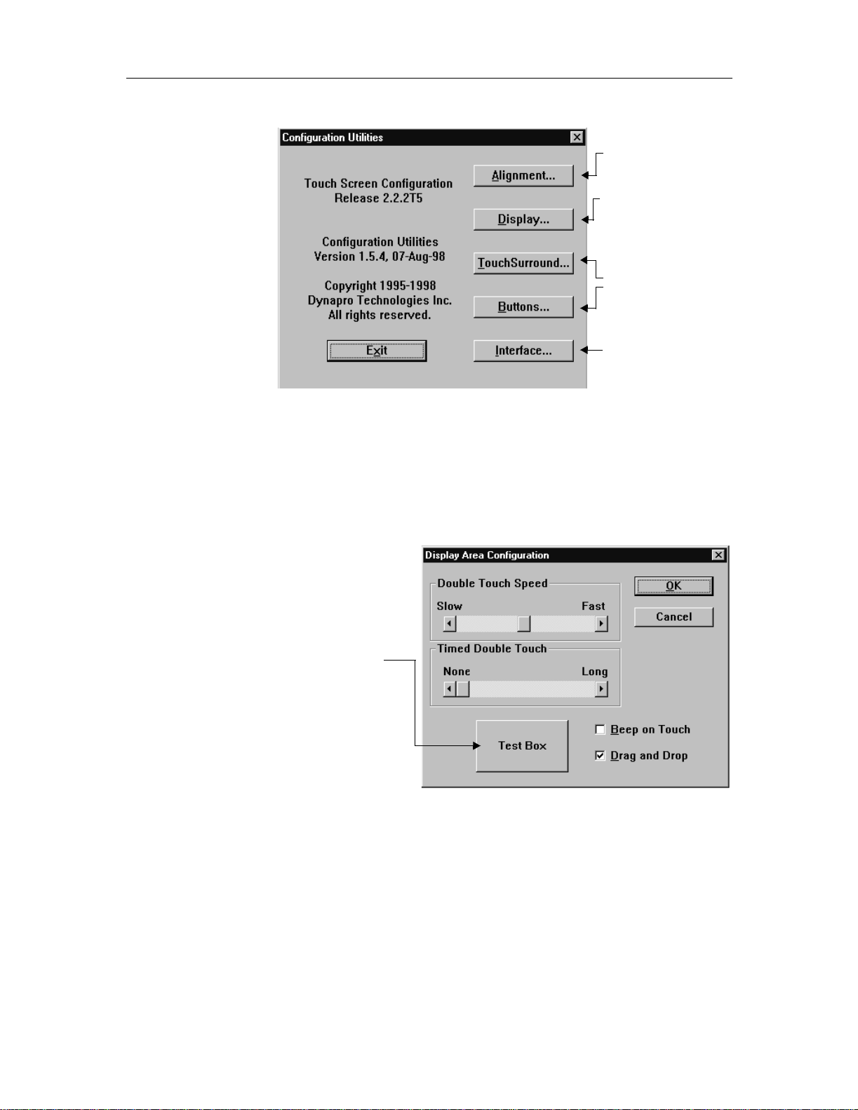
In the NFI Setup and Diagnostic Utility dialog box, select Configuration.
The Configuration Utilities dialog box appears.
» Configuration.
.
3M Touch Systems Proprietary Information
9
Page 14
MicroTouch
.
.
S
a
D
o
T
T
c
s
TM
Near Field ImagingTM (NFI) Software User’s Guide
Align the touch screen
before using it. See
Chapter 1.
Customize touch
responses.
Configure the
TouchSurround
and def ine the
TouchSurround buttons
See Chapt er 3, C ha pter
4, and Chapter 5.
Change controller
communication
paramet ers or se nsi tiv it y
TM
area
Customizing touch responses
Use the Display Area Configuration dialog box to adjust the touch responses of
the touch screen . This step is necessary only if you want to change the default
settings for the touch screen.
1. In the Configuration Utilities dialog box, select Display.
elect the Test Box
fter adjusting the
ouble Touch Speed
r Timed Double
ouch sliders. The
est Box changes
olor when you
uccessf ully touch it.
2. Configure th e options below.
3. After you’ve c onfigured the setti ngs, s ele ct OK to save them or touch Cance l
to discard the changes and revert to the previous s ettings.
3M Touch Systems Proprietary Information
10
Page 15

Chapter 2: Customizing the software
Doubl e Touch Speed and Timed Double Touch
The NFI touch screen can det ect a double touch, which is the same a s doubleclicking the mouse. To generate two separate touche s, touch the screen twice
slowly.
To use the double touc h fea ture do one of the following:
Touch the touch screen twice quickly as if you were double-clicking the
mouse. This is th e default option.
Use the Double Touch Speed slider t o incre ase or decre ase the t ime the touch
screen al lo w s b et w een touches.
If you increase the speed too much, it may become difficult to generate a
double touch; th e touche s will inst ead be rec ognize d as two separat e tou ches.
If you decrease the speed too much, what you intend to be two separate
touches might instead be recognized as a double touch.
Touch the touch screen and hold it. To use this option, adjust the Timed
Double Touch slider.
Use the Timed Double Touch slider to increase or decrea se the time th e
touch screen waits before acknowledging a double touch.
If you increase the slider to Long, it takes about two seconds to generate a
double touch.
If you decrease the sli der to just off None, it take s ab out 0.2 seconds.
A timed double touch is generated on the initial touch only, not after
dragging.
Beep on Touch
Select this op tion to have the computer beep on each first touch.
Drag and Drop
Check this box if you want the pointer to follow your finger around the screen
until you rele ase it. Thi s allows you t o select an ob ject on the screen, dra g it across
the screen to a new location, and then drop it in its new position by releasing the
touch.
Important
For optimal performance, do not choose drag and drop unless your application requires it.
3M Touch Systems Proprietary Information
11
Page 16
MicroTouch
TM
Near Field ImagingTM (NFI) Software User’s Guide
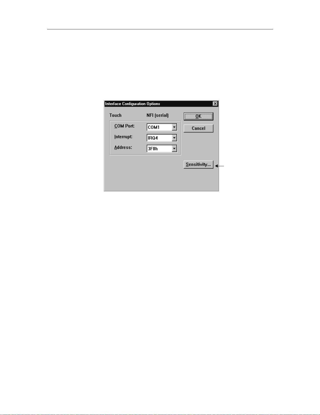
Changing the controller communications parameters
Use the Interface Configuration Options dial og box to change the
communications parameters needed to communicate with the NFI touch screen
controller.
This step is ne ces sary o nly if you want t o change th e communi cati on set tings you
selected during installation.
1. In the Configuration Utilities dial og box, select Interface.
Change the
sensitivity of the
touch sc reen.
2. Configure th e options below.
3. After you’ve c onfigure d t he sett ing s, se lect OK to s ave t hem o r selec t Canc el
to discard the changes and revert to the previous s ettings.
COM Port
Sets the serial communic ation port. Selec ting a port automatically fills the
Interrupt and Addres s boxes with the default valu es for the port. To use custom
combinations, select the Interrupt and Address individually .
Interrupt
Sets the interrupt request number used by the NFI touch screen controller to
interrupt the oper ating syst em. If you are using a standard COM port, you shoul d
need to use only the default values in the Interrupt box.
Address
Sets the I/O base address used by the touch screen controller. If you are using a
standard COM port , you should need to use o nly the de fault value s in the Add ress
box.
Sensitivity
Use the Sensit ivity Con figuration di alog box to change th e touch sens itivity of t he
NFI touch screen.
This step is nece ssary only if you want to change the def ault sensit ivity setti ngs of
the touch screen to allow for the way you’re touching the screen (finger, gloves,
alignment tool), the mounting of the touch screen, and the surrounding
environment.
3M Touch Systems Proprietary Information
12
Page 17
Chapter 2: Customizing the software
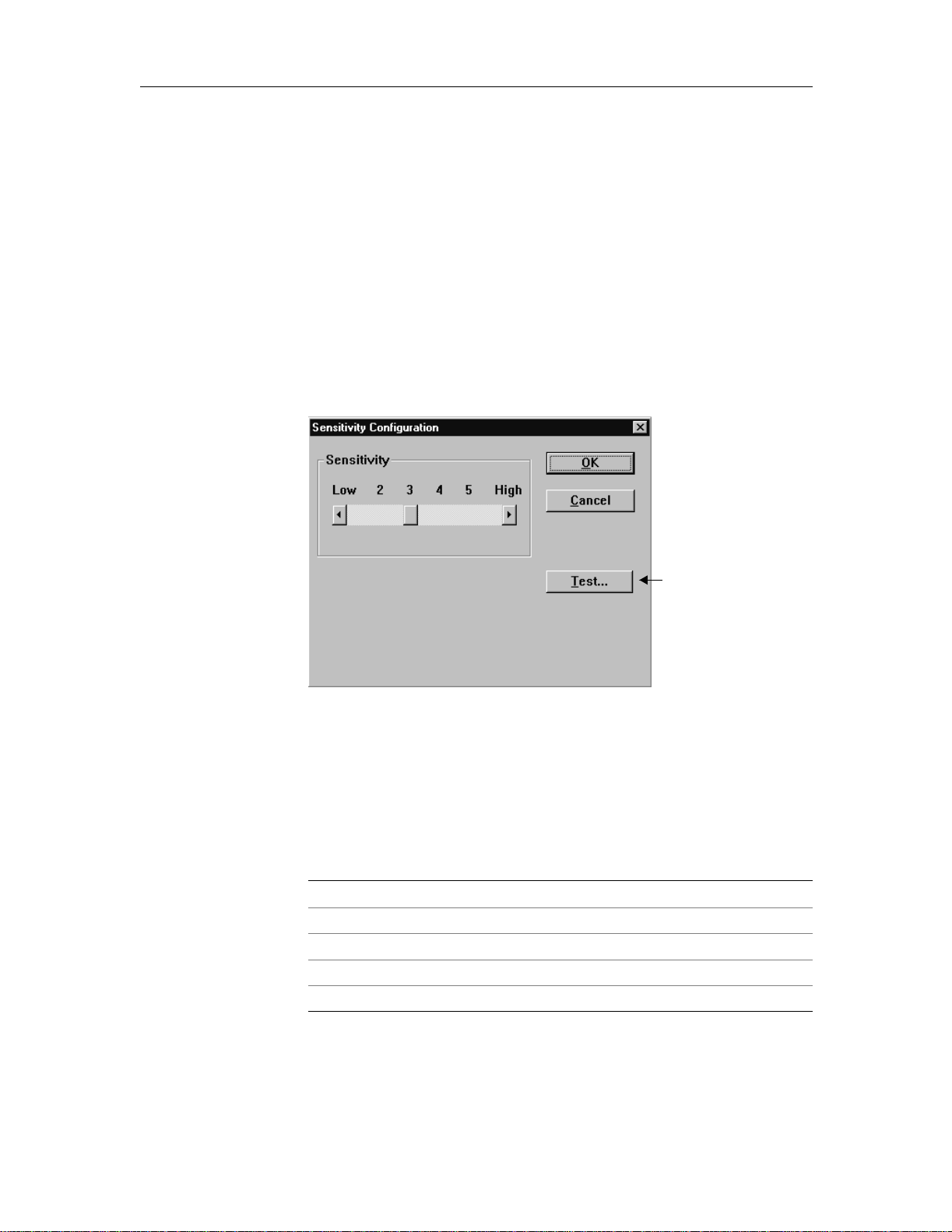
Use the Sensitivity slider to increase or decrease the sens itivity of the touch
screen.
If you in c r ease the se nsitivi ty to Hi g h , th e to u ch scre en is v e r y se n sitive an d
touches may be de tected be fore the fing er actually t ouches t he screen. Thi s setting
is useful when wearing heavy or thick gloves.
If you decrease t he sensiti vity to Low, the touch screen is not as respons ive but it’ s
also less likely to detect false touches. This setting is useful when using an
alignment tool or a fi nger without gloves.
To adjust the Sensitivity slider:
1. In the Interface Configuration Options dialog box, select Sensitivity.
2. In the Sensitivity Configuration dialog box, adjust the slider to the desired
setting (Table A).
After you adjust
the Sensitivity
slider, sele ct the
Test butto n.
3. Select Test to c onfirm the settings for the Sensitivity slider.
4. Follo w th e on- s c r ee n in s t r u ct io n s .
5. After you’ve configured the setting, select OK to save it or select Cancel to
discard the change and revert to the previous setting.
T able A: Recommended sensitivity settings
Method of touching the screen Recommended setting
Bare fin ge r/latex glov e 1 or higher
Alignm en t t oo l 2 or higher
Cloth glove 3 or higher
Leath er glove 3 or higher
Rubber gl ov e 4 or higher
3M Touch Systems Proprietary Information
13
Page 18
MicroTouch
TM
Near Field ImagingTM (NFI) Software User’s Guide
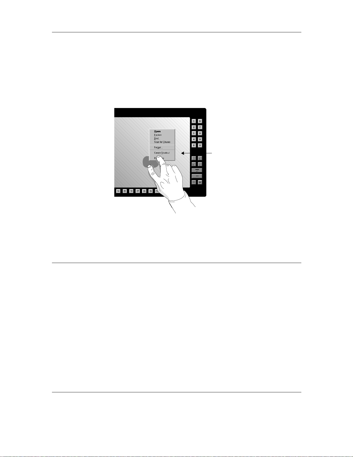
Using right-mouse button support
You can open the same menu that would appear if you clicked an object with the
right-mouse butt on.
To open an object’s menu:
1. Touch an object to select it. Leave your finger there.
2. Using another finger, touch the screen briefly diagonally opposite the first
touch, to open the r ight-mouse menu.
While holding your index finger on the
scree n, use your middle finger to
touch the screen diagonally opposite
the first touch.
Note: The second touch won’t register
if it is in the same horizontal or vertical
plane as the first touch.
Operating a mouse and touch screen at the same time
The touch screen driver supports concurrent mouse and touch screen operation.
This allows you to use both a mouse and the touch screen.
Windows NT 4.0 Windows 98, Windows 95
To use a mouse and touch screen at the same time,
inst all t he mou se dr i ve r an d th en t he t ouch scr e en dr i ve r.
Windows NT 4.0 leaves the previous mouse driver active
when the new one is installed. The next time you start
Window s NT 4.0, bo t h to uc h sc r ee n an d mo us e should
operate.
Disabling the mo use driver
When you in stall the mouse dr iver , it wil l always be active,
even if you in st a ll a dif f ere nt type of mo us e dri ver l ater. If
you unplug the mouse from your computer and restart
Windows NT 4.0, the mouse driver will fail to load,
resulting in an error message.
To disable the mouse driver:
1. Open the Device dialog box in the Control Panel.
2. Highlight the entry for the mouse driver.
3. Choose Startup to change its startup stat e to
disabled.
The touch screen driver supports concurrent mouse and
touch scre en ope rat io n i n Wind ows 95 an d Wi n do ws 98.
To install a mouse driver:
1. Connect a mouse to your computer.
2. Select the Windows Start button
Control Panel.
3. Select Add New Hardware.
4. Select Yes, to have the Wizard detect new hardware
for you. Do not select No to install a mouse driver
manually.
5. Follow the on-screen instructions to install the
mouse.
Once the mouse has been detected and the appropriate
mouse driver installed, the mouse will operate at the
same time as the touch screen.
If the Wiza rd does not de tect your mouse, you can not use
it at the same time as th e touch screen. You must use a
mouse that Windows 98 or Windows 95 detects
automatically, such as one by Microsoft or Logitech.
» Settings »
3M Touch Systems Proprietary Information
14
Page 19
Windows 3.1 op erating system
Starting the software
To start the software, do the following:
In the Windows Program Manager, select Main Group » Control Panel » Touch
Screen.
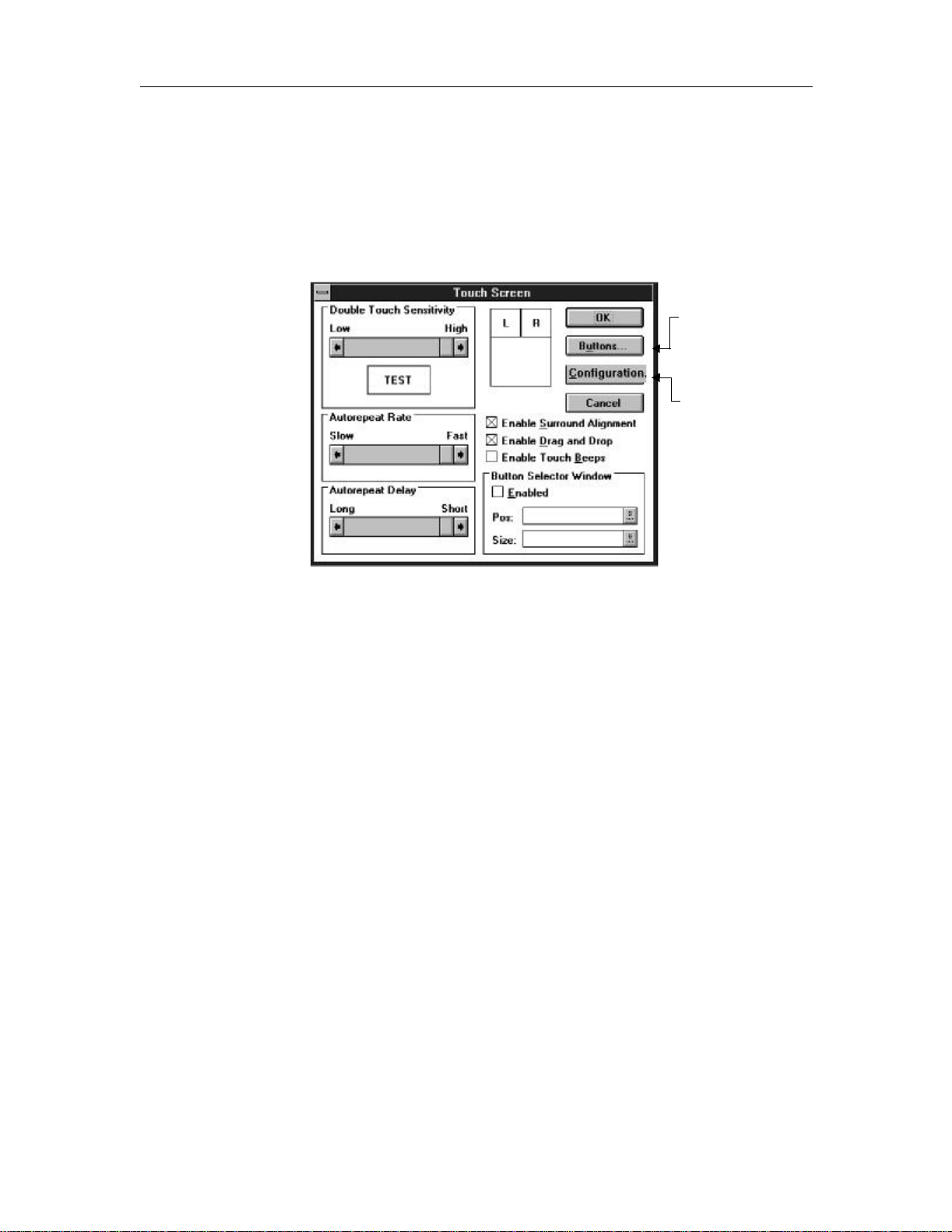
The Touch Screen dialog box appears.
Chapter 2: Customizing the software
Define
TouchSurround
buttons (see, Chapter
4, and Chapt e r 5) .
Align the touch screen
(using Calibration
button) before using
the touch screen (see
Chapter 2) .
TM
Customizing touch responses
Use the Touch Screen dialog box to change the touch screen char ac teristics.
1. Complete the options as described below.
2. After you have configured the following options, selec t OK to save the
settings.
To return all parameters to their last configured values, select the Cancel but ton.
The Cancel button does not undo any alignment that was performed from the
Alignment butt on.
Doubl e Touch Sensitivity
The NFI touch screen can det ect a double touch, which is the same a s doubleclicking the mouse. To generate two separate touche s, touch the screen twice
slowly.
Touch the touch screen twice quickly as if you were double-clicking the mouse.
This is the default option.
Use the Double Touch Sensit ivity slid er to increas e or decrease the tim e the touch
screen al lo w s b et w een touches.
If you increase the speed too much, it may become difficult to generate a double
touch; the touches will instead be recognized as two separate touches.
If you decrease the speed too much, what you intend to be two separate touches
might instead be recognized as a double touch.
3M Touch Systems Proprietary Information
15
Page 20

MicroTouch
TM
Near Field ImagingTM (NFI) Software User’s Guide
Autorepeat Rate
This setting is only for the TouchSurround
TM
underlay.
Use the sli der to set the aut orepeat rate for buttons on the touch screen. If you set
the rate t o Fast, holdi ng a tou ch will produ ce rapid r epeat event s. If you se t the rate
to Slow, the sa me touch will genera te f ewer repeat events in the same length of
time.
Autorepeat affects only events generated by but ton presses. It does not affect
events generated by button releases.
Autorepeat Delay
This setting is only for the TouchSurround underlay.
Use the slider to set the time r equired for a touch to be he ld before autorepe at
mode begins. A Short delay mea ns you d on’t need to hold a touc h very long before
autorepeat t ouch es are ge nerated. A Long del ay mea ns tha t you must hol d a t ouch
longer to begin genera ting autorepeat touches.
Enable Surround Alig nm ent
Select this che ck box to align the TouchSurround underlay (see “Aligning the
TouchSurround underlay” on page 33).
Enable Drag and Drop
Check this box if you want the pointer to follow your finger around the screen
until you rele ase it. Thi s allows you t o select an ob ject on the screen, dra g it across
the screen to a new location, and then drop it in its new position by releasing the
touch.
Important
For optimal performance, do not ch oose dragand drop unless your application requires it.
Enable To uch Beeps
Select this op tion to have the computer beep on each first touch.
Button Selector Window
Use the Bu tton Selector Window to select e ither right- or left-mouse button click
emulation in response to a touch. When enabled, this window appears displaying
the picture of a mouse. The active button, left or right, is highlighted in black.
When you select this wind ow, th e pointe r does not a ppear ins ide th e windo w, but
remains in its last position. This reminds you where you were last touching. The
Button Selector window appears on top of other windows.
To enable thi s window, sele ct t he Ena bled b ox. The Pos iti on (Pos ) and Siz e fiel ds
display the current position and size of the Button Selector window.
Changing the communications parameters
To change the inst allation settings, including sensitivity, see “Changing the
communications parameters” on page 20.
3M Touch Systems Proprietary Information
16
Page 21

Operating a mouse and touch screen at the same time
The touch screen driver supports c oncurren t mouse an d touch s creen opera tion in
Windows 3.1, windowed MS-DOS sessions, and full-screen MS-DOS sessions.
To use the touch screen and mous e at the same time:
1. From Program Manager, select the Not epad icon.
2. On the file menu, select Open.
3. Open autoexec.bat.
4. Move the line containing the mouse driver before the line containing
emouse.com.
5. On the File menu, sel ect Save.
6. Restart your c omputer.
Be sure to connect th e mouse before starting your computer, so the driver can
detect the mouse whe n i t lo ads.
MS-DOS operating system
Aligning the touch screen
Before you ca n us e the touch screen, you must use the NFI Setup and Diagnostic
Utility di alog box to initialize and align the screen. Alignment orients and aligns
the touch screen with the video display (see “MS-DOS” on page 7).
Chapter 2: Customizing the software
Customizing the touch screen
For most applicat ions the default touch scre en configuration is appropriate. To
change the configuration, use the options in the emouse utility.
The emouse utility (emouse.com) allows the touch screen’s display area to react
to finger touche s as if they were the movements of a pointer driven by a singlebutton mouse. This means you ca n use off-the-shelf programs that requi re a
Microsoft-compatible mouse.
To view the options, at the MS-DOS prompt, type EMOUSE /?, and the n pres s
Enter.
For de ta ils about t he T ouchSurround un derlay , see Chapt er 5 “Co nfigu ring
TouchSurround features: MS-DOS”.
You can configure the to support this feature
Disp la y ar e a Drag
TouchS urround ar ea Autorepeat
Autorepeat Holdoff (Delay)
Autorepeat Interval
Display area and the TouchSurround area Beep
Touch event proce ssing
3M Touch Systems Proprietary Information
17
Page 22

MicroTouch
TM
Near Field ImagingTM (NFI) Software User’s Guide
During instal lation of the touch screen dri vers and utilit ies, the autoexec.ba t file is
modified to include the following line:
C:\TOUCH\DOS\EMOUSE.COM
This line loads the emouse.com pr ogr am into memory, where it stays resident.
Important
Do not remove this line from the autoexec.bat file, or you will not be able to use the touch
screen with your MS- DOS applications
If you start applications from the autoexec.bat file, ensure that the emouse.com
appears before you start any applications.
To configure the Touc hS urroundTM area or display area fo r all sessions:
1. Use a text editor (such as ed it.exe) to open the autoexec.bat file.
2. Add one or more of the parameters shown in Table B to the emouse.com
command.
3. Save the changes.
4. Restart your c omputer so the changes will ta ke effect.
Example of an autoexec.bat file
EMOUSE /BEEP=OFF /INT=3 /SENS=4
/DEFINE=C:\TOUCH\DOS\MYFILE.DEF
Inclu d e spaces as s h o w n in th is exampl e.
In this ex ample, emo u se.com:
turns off touch event beeps ( /BEEP=OFF)
sets the touch event interval to 3 ( /INT=3)
sets th e sensitivity of th e touc h sc r een to 4 ( /SE N S =4)
uses button definitions from C:\TOUCH\DOS\MYFILE.DEF
( /DEFINE=C:\TOUCH\DOS\MYFILE.DEF)
To change the TouchSurround area or display area settings for the current MSDOS session only:
1. At the MS-DOS prompt, type
EMOUSE <options>
where <options> is one or more of the configuration options shown in Table
B.
2. Press Enter
3M Touch Systems Proprietary Information
18
Page 23

Chapter 2: Customizing the software
In Table B, characters in bold italics are the minimum entry for each option. You
can use the whole word or any abbreviation that include s the m inimum entry.
T able B: TouchSur roundTM area and display area configuration options
Option Description
/AUTOREPEAT={OFF|ON} Enables or disables TouchSurround button
autorepeat.
When autorepeat is enabled, the button will activate
the first time you t ouch it and its press action wil l
repeat for as long as you hold your finger on the
button.
When autorepeat is disabled, the button’s press
action activates once only, every time you touch the
button.
The default is /AUTOREPEAT=ON.
/BASE=<I/O base address> Sets the I/O base address for the touch controller’s
communications por t.
/BEEP={OFF |ON} Enables or di sab les to uc h eve nt bee p s in t he disp la y
/COM1 /COM2 /COM3
/COM4
/DEFINE={filename} Reads TouchSurround button definitions from the
/DRAG={OFF|O N} Enabl es or disa bl es dr ag mov eme nt (dr ag -an d- dro p)
/HOLDOFF=<dur a tio n> Sets t he pe rio d o f ti me r equi re d for a to uch t o b e hel d
/INTERVAL=<interval> Sets the autorepeat interval—that is, how quickly the
area and TouchSurround are a.
The default is /BEEP=OFF.
Sets th e touch controller’s commu nications port.
If you change the COM port from the default of 1,
ensure you change the COM port set ting in the NFI
Setup and Diagnostic Utility (see “Changing the
communications par ameters” on page 16).
specified file.
in the display area of the touc h screen.
When drag is enabled, the cursor follows your finger
as you move it around the touch screen.
When drag is disa bled, the curs or rema ins w here you
first touched the screen.
The default is /DRAG=ON.
before it begins autorepeating.
A Short duration means that you don’t need to hold a
touch ve ry long before autorepeat touches are
generated.
A Long duration means that you must hold a touch
longer to begin generating autorep eat touches.
The range is 0 to 10. A value of 0 results in a
continuous stream of touch events from the moment
you first touch t he screen, while a value of 10 results
in a dela y of approximately one second between the
first and subsequent touch events.
The default is /HOLDOFF=5.
autorepeat feature repeats the touch.
If you set the rate to 10, holding a touch will produce
rapid repeat events.
If you set the rate to 0, the same touch will generate
fewer repeat events in the same length of time.
The range is 0 to 10.
The default is /INTERVAL=5.
3M Touch Systems Proprietary Information
19
Page 24

MicroTouch
TM
Near Field ImagingTM (NFI) Software User’s Guide
T able B: TouchSur roundTM area and display area configuration options
Option Description
/IRQ=<IRQ number> Sets the interrupt request line for the touch
/SENSIVITY={1/2/3/4/5/6} Use the Sensitivity setting to increase or decrease the
/TOUCH={OFF|ON} Enables or disables touch event processing for both
controller’s communications po rt.
sensit ivity of the touch screen.
If you increase the sensitivity to High, the touch
screen i s ver y sensit ive a nd tou ches ma y be d etect ed
before the finger actually touches the screen. This
setting is useful when wearing heavy gloves.
If you decrease the sensitivity to Low, the touch
screen is not as responsive but it’s also less likely to
detect fa lse touc hes. This set ting is useful whe n using
an alignment too l or a finger without gloves.
The default is 3.
the display area and the TouchSurround
The default is /TOUCH=ON.
Tip: Type EMOUSE /TOUCH=OFF at the command
line to dis ab le th e touc h scr een fo r clea ni ng . You can
also define a Touch Surround button to enable or
disabl e the t ouc h sc ree n (see “ Su mma ry of st ep s ” on
page 44).
TM
area
Changing the communications parameters
To change the installation settings, man ually enter the IRQ and base settin gs for
the touch scre en dr i ver in th e aut oex ec. ba t fil e to ma tc h the ha rdw ar e bei ng use d.
During installation, a line is added to the auto exec.bat file. Here’s an example:
\TOUCH\DOS\EMOUSE /COM1
To change the IRQ and base settings, replace /C O M 1 with:
/IRQ = XX /BASE = YYY
where XX is the interrupt request number for the COM port and YYY is its I/O
base address (in he xadecimal).
For reference, the following table lists the default COM settings.
COM settings IRQ settings Base settings
COM 1 4 3F8
COM 2 3 2F8
COM 3 4 3E8
COM 4 3 2E8
After changing and saving the file, restart the computer.
For details about advanced COM port options, s ee the Readme file.
3M Touch Systems Proprietary Information
20
Page 25

Chapter 2: Customizing the software
Operating a mouse and touch screen at the same time
To use a mou se at the same ti me as the touch scr een, load the mouse drive r i n
autoex ec .b a t be f o re load ing emouse.com:
1. At the command prompt, type EDIT C:\AUTOEXEC.BAT where C is the
drive le tter of the hard di sk .
2. Move the line containing the mouse driver before the line containing
emouse.com.
3. On the File menu, select S ave. Alternatively, press Alt + S.
4. Restart your c omputer.
Be sure to connect th e mouse before starting your computer, so the driver can
detect the mouse whe n i t lo ads.
3M Touch Systems Proprietary Information
21
Page 26

Page 27

CHAPTER 3
Configuring TouchSurroundTM
features: Windows NT 4.0,
Windows 98, and Windows 95
What is the TouchSurround underlay?
The NFI touch screen syste m can be used with an optional TouchSurround
underlay. The TouchSur round unde rlay all ows you to u se pa rt of t he touch s creen
to define keys, such as the ones on a keyboard. This underla y may be us ed in
situations where the touch s cr een is larger than the display.
Figure 1: Example of a TouchSurround underlay
Aligning the TouchSurroun d underlay
Most applicati ons do not require the TouchS urround underlay opt ion. Do not align
the TouchSurround underlay unless a specific application calls for its use.
To align the TouchSurround underlay:
1. Select the Windows Start button, point to Programs, Touch Screen Utilities,
and then select Configuration.
3M Touch Systems Proprietary Information
23
Page 28

MicroTouch
TM
Near Field ImagingTM (NFI) Software User’s Guide
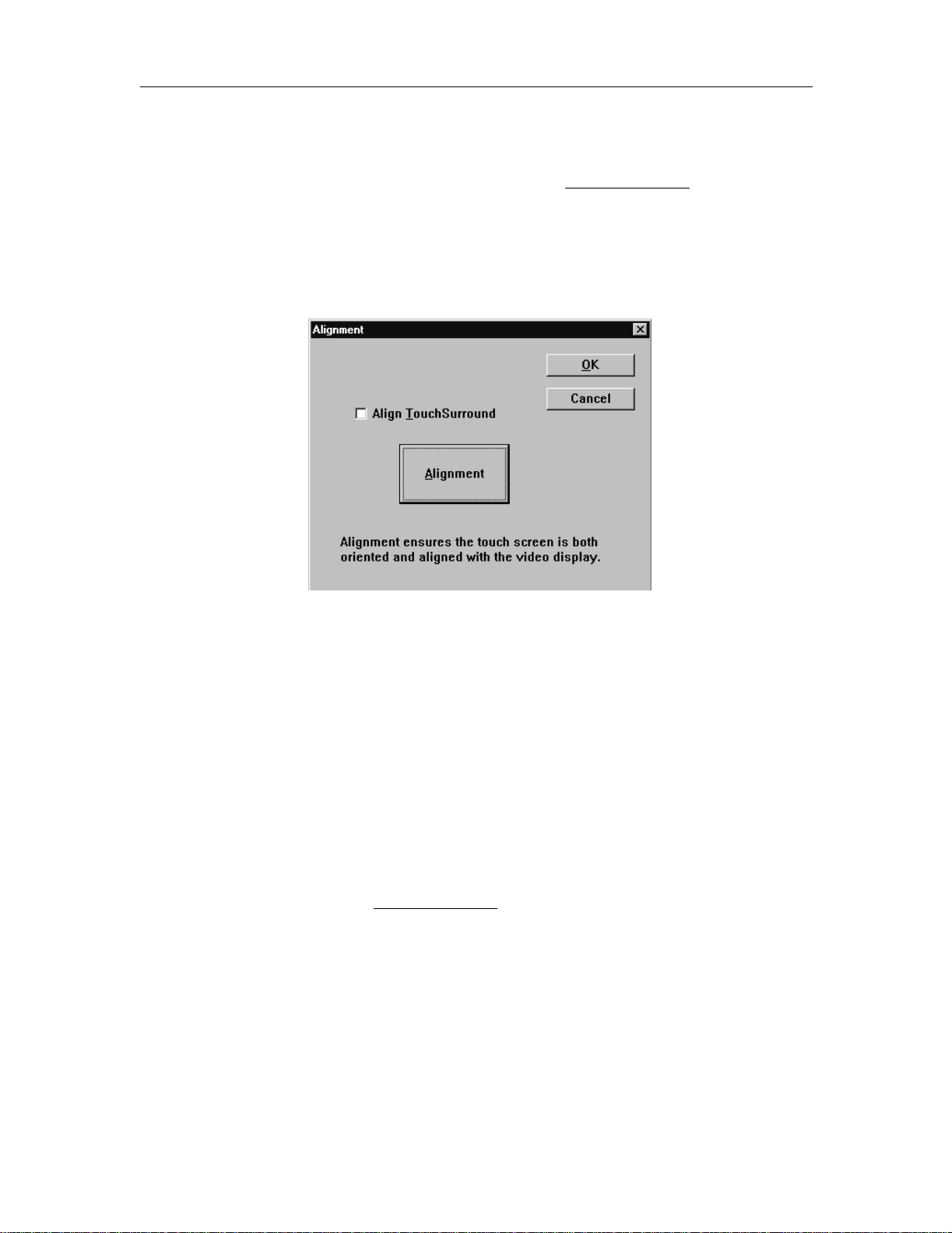
2. In the Configuration Utilities dialog box, select Alignment.
3. In the Alignment dialog box, select the Align TouchSurround
4. Select Alignm ent.
TM
check box.
Be sure you are directly in front of the touch screen. Use a finger or
alignment tool to align the TouchSurround underlay. An alignment tool
produces a more accurate alignment.
5. To align, follow the on-screen instructions. To cancel alignment wi thout any
changes, press ESC at any time.
When fin ished, the new align m e n t takes effe ct immediat el y an d th e
Alignment dialog box reappears.
6. T est t he alig nment by moving the pointe r aroun d the scree n wit h your finger.
If it is satisfactory, select OK. Otherwise select Alignment and complete the
procedure again.
3M Touch Systems Proprietary Information
24
Page 29

Chapter 3: Configuri ng TouchSurround
TM
features: Windows NT 4.0, Windows 98, and Windows 95
Customizing touch responses in the TouchSurround area
Use the TouchSurround Configuration dialog box to customize the touch
responses of the TouchS urround buttons.
This step is neces sar y only if you wish to change the default settings for the
TouchSurround buttons.
1. In the Configuration Utilities dial og box, select TouchSurround.
2. Configure th e options below.
3. After you’ve con figur ed the op tio ns, se lect OK t o save the m or se lect Cance l
to discard the changes and revert to the previous s ettings.
Autorep eat Rate
The autorepeat rate is the rate at which repeat act ions are generated when a touch
is held.
Use the slider to set the autorepeat rate for buttons on the TouchSurround
underlay. If you s et the rate to F as t, hol din g a t ouch pr oduc es r apid re peat act ions.
If you set the rate to Slow, the same touch generates fewer repeat actions in the
same length of tim e.
Autorepeat affects only actions generated by button presses. It does not affect
actions generated by button releases.
Autorepeat De lay
The autorepeat delay is the amount of time the touch screen waits before
generating autorepeat actions.
Use the slider to set the time r equired for a touch to be he ld before autorepe at
mode begins. A Short delay mea ns you d on’t need to hold a touc h very long before
autorepeat t ouch es are ge nerated. A Long del ay mea ns tha t you must hol d a t ouch
longer to begin genera ting autorepeat touches.
3M Touch Systems Proprietary Information
25
Page 30

MicroTouch
TM
Near Field ImagingTM (NFI) Software User’s Guide
Beep on Touch
Select this box if you want the computer to beep whenever a TouchSurroundTM
button is activated by a touch or release.
The beep o ccurs only o n the f irs t t ouch of the sc reen. The bee p won’t r epeat if you
move your finger around the display area before releasing it.
Adding TouchSurr o und button s
You can define the size, position, activation, and function of the TouchSurround
buttons, and you can define buttons as function keys, command keys, calculator
keys, screen change controls, or whatever other format you requi re.
TouchSurround butt ons are ina ctive whil e you are defining but tons. They be come
active when you save the definitions and exit the softwa re.
Important
T o optimize performance of a new TouchSurround button, ensure you position the button
at least 0. 25 inch es ( 6 .4mm) fr om the e dg e o f you r prod uc t’ s be ze l. In a ddi t ion, e nsu re t he
size of the button is at least the size of your index finger’s fingerprint (about 0.70 inches or
17.8mm on each side).
Summary of steps
To add a TouchSurround button definition do the foll owing:
1. Set up a new button defini tion in the TouchSurround Button Definitions
dialog box.
2. Define the new button’s coordinates.
3. Define the new button’s press and release actions.
4. If desired, select the autorepeat check box.
5. Test the new button defini tion.
3M Touch Systems Proprietary Information
26
Page 31

Chapter 3: Configuri ng TouchSurround
nd
s
is
Set up a new button def ini t ion
To set up a new button:
1. In the Configuration Utilities dialog box, select Buttons.
For information about the
entries in this list, see
“Reviewing button
defini tions” on page 30.
Each line in the list is a
different button definition.
The location and function of the
selec te d bu t to n is sh ow n her e .
If buttons have not bee n defined, the list is blank.
TM
features: Windows NT 4.0, Windows 98, and Windows 95
To add or appe
button definition
to the list, use th
button.
2. To dis play options for defining button location and press/re lease action, do
one of the following:
Select Append to add the button definition to the end of the list.
The Define a Button dia log box appears.
Select a butt on defini ti on in the li st: the Append bu tto n change s to Insert .
Select Insert to add a new button definition above the selected button.
The Define a Button dia log box appears.
Define the new button’s coordinates
To use a new button, you must defi ne its coordinates. The coordinates of a
button’s upper left and lower righ t corners define the but ton’s size an d its position
on the TouchSurround underlay.
To ensure accuracy, use an alignment tool to define the button’s coordinates .
While defining a Touch Su rround button, do not rest your hand anywhere on the
surface of the touch scree n or bezel bec ause the pres ence of your hand aff ects the
values passed to the screen.
3M Touch Systems Proprietary Information
27
Page 32

MicroTouch
TM
Near Field ImagingTM (NFI) Software User’s Guide
To define the button’s coordinates:
1. Hold the alignment tool at a 90-degree angle to the screen’s surface, and
touch the Upper Left box in the Define a Button dialog box.
Define the siz e an d
position of the
button by touching
the screen, or by
entering its X and Y
coordinates here,
separ ated by a
spac e. If yo u tou c h
the screen, the
coordinates are
entered
automatically.
2. Touch the point on the TouchSurround
the upper left corner of the new button.
Align the
alignment tool
with the inside
edges of the
button’s corne r
TM
area where you want to posit ion
76019_A
3. Touch where you want to position the button’s lower right corner.
The coordinate s of t he areas y ou t ouched a re dis playe d in t he Up per Left b ox
and Lower Right box.
3M Touch Systems Proprietary Information
28
Page 33

Chapter 3: Configuri ng TouchSurround
Define the new button’s press and release actions
Button actions are performed either when th e button is pressed or release d. A
button can either perform a command or inject a string, not both.
Command s con trol w hat o perati ons a re p erfor med wh en a bu tton is ac tivat ed.
See “Button commands” on page 61.
Strings are passed to the active window when the button is pressed or
released. See “Strings” on page 62.
Select the Autorepeat check box
If desired, select the Autorepeat check box to enable autore pea t for the button’s
press action.
When autor epea t i s enab led , t he bu tto n activ at es the f irst tim e you tou ch i t an d its
press action repea ts for as long as you hold your finger on the button.
When autorepeat is dis abled, the button’s pre ss ac tion activates once only, every
time you touch the button.
Test the new button definition
1. When finished, do one of the following:
TM
features: Windows NT 4.0, Windows 98, and Windows 95
Select OK to start a diagnostic test of the button definition.
If the definition is valid, it is added to the button definition list. If the
button definition is incorrect, an error message is displayed. See “Fixing
overlapping buttons”.
Select Cancel to discard the button definition.
2. Repeat the above steps for each button definition.
3. When finished defining buttons, select OK in the TouchSurround Button
Definitions dialog box to save the button definition(s).
Fixing overlapping buttons
Buttons ca nnot ove rlap. If you def ine a button t hat overla ps an exis ting but ton , an
error message appears, and the button definition is not saved.
To help find t he button wi th the confl icting c oordinates, touch the Touc hSurround
area where you encountered the overlap. This wil l dis play the button definition
information for any button defined in that area. Then either modify the original
button coordinates or define a new button with new coor dinates.
To correct the problem, do one of the following:
Select Cancel from the TouchS urround Button Definit ions dialog box to clear
the button definition.
Define new coordinates for the button.
3M Touch Systems Proprietary Information
29
Page 34

MicroTouch
s
TM
Near Field ImagingTM (NFI) Software User’s Guide
Reviewing button definitions
You can check the function of a To uchSurroundTM button by reviewing the
information in the TouchSurround Button Definitions dialog box.
To check the function of a button:
1. Open the Configurat ion Utilities dialog box.
2. Select Buttons to open a list of button definitions. The list is blank if no
buttons have been defined.
3. Touch a button in the list. The button’s location and function are shown at
the bottom of the dialog box. For an example of the dialog box, see the one
that follows.
The information in the TouchSurround Button Definitions dialog box is in
columns. Table C provides a key to the informatio n in the columns.
See Table C for
definitions of
these co lu mns.
The location and
function of the
elected button is
also sho wn here.
T able C: TouchSurround button definitions column key
Column Contents Value
1 Indic ates whethe r a command or string is defined for
the button’s press action.
2 Indicates whether autor epeat is en abled. If the button
has a press act ion , you can make that action r epeat f or
as long as the button is pressed.
3 The command or string for the button’s press action. Command or string
4 Indic ates whethe r a command or string is defined for
the butto n’s re le as e ac tio n.
5 The command or string for the button’s release action. Command or string
C (for command) or
S (for string)
A (or blank)
C (for command) or
S (for string)
3M Touch Systems Proprietary Information
30
Page 35

Chapter 3: Configuri ng TouchSurround
h
TM
features: Windows NT 4.0, Windows 98, and Windows 95
Editing and deleting button definitions
To edit a button definition:
1. Open the Configurat ion Utilities dialog box.
2. Select buttons to display the list of button definitions.
The numb er of
buttons in the list is
shown he r e.
The location and function of
the selec te d bu tt o n is
shown he r e.
Choose the
button definition
you want to
edit...
...and then touc
Edit.
3. Select a button definition, then select Edit, or double touch a button
definition.
4. Change the button definition as required, and then sele ct OK to return to the
list of button definitions.
5. To save the changes, select OK. To quit without saving change s, select
Cancel.
To delete a button de finition:
1. Open the Configurat ion Utilities dialog box.
2. Select Buttons to display the list of but ton definitions.
3. Select a button definition from the list, and then select Delete to delete the
button definition.
4. To save your changes, select OK. To restore the button definition, select
Cancel.
Copying custom button definitions to multiple computers
Use the Touch Screen Configuration Import/Export Utility (touchini.exe) to
generate a file that can be copied and imported to othe r com puters. Using this
utilit y elimin at es t he nee d to confi gure e ach c ompute r m anual ly wi th the sa me set
of button definitions.
The Touch Screen Confi guration Import/Expo rt Utility is install ed when you
install the touch screen drivers and util ities. This utility is copied to:
3M Touch Systems Proprietary Information
31
Page 36

MicroTouch
TM
Near Field ImagingTM (NFI) Software User’s Guide
the \TOUCH\NT folder on your computer’s hard disk
for Windows NT 4.0
the \TOUCH\W9X folder on your comp uter’s hard disk
for Windows 98 and Windows 95
Exporting button definitions
To export button de finitions from the registry to a file:
1. Select the W ind ows S tart butt on, select Pr ogram s, and then sele ct Command
Prompt.
2. At the command prompt, type
CD\TOUCH\NT for Win dows NT 4.0
CD\TOUCH\W9X for Windows 98 and Windows 95
3. Type TOUCHINI /o wher e o = output.
This creates a file with the default file name TOUCH.INI. This file contains
an ASCII representat ion of the touch screen configurat ion.
4. To change the file name, specify a new file name after the /o parameter. For
example, if you type T OUCHINI /oCONFIG.INI, the file will be named
CONFIG.INI. The file is placed in either the Windows NT 4.0 folder or the
Windows 98 and Windows 95 folder.
Importing button definitions
Important
When you import a TouchSurroundTM definition file, the existing TouchSurround
configuration is erased.
To import button definitions into the registry from a file:
1. Select the W ind ows S tart butt on, select Pr ogram s, and then sele ct Command
Prompt.
2. At the command prompt, type
CD\TOUCH\NT for Win dows NT 4.0
CD\TOUCH\W9X for Windows 98 and Windows 95
Type TOUCHINI /i<filename>
where <filename> is the file you created in either step 3 or step 4 of the
above procedure for exporting button definitions.
The new configuration takes effect the next time you start
Windows NT 4.0, Windows 98, and Windows 95.
3M Touch Systems Proprietary Information
32
Page 37

CHAPTER 4
Configuring TouchSurroundTM
features: Windows 3.1
What is the TouchSurround underlay?
The NFI touch screen system can be used with an opt ional TouchSurround
underlay. The TouchSurround underlay (illustrated in Chapter 3, page Figure 1)
allows you to use part of the tou ch scre en to define keys, such as the ones on a
keyboard. This underlay would be used in situations where the touch screen is
larger th an th e display.
Aligning the TouchSurroun d underlay
Most applications do not require the TouchSurround option. Do not align the
TouchSurround underlay unless a specific application calls for it s use.
To align the TouchSurround underlay:
1. In the Windows Program Manager, open the Main group.
2. Open the Control Panel.
3. Open Touch Screen in the Control Panel.
4. In the Touch Screen dialog box, sel ect t he Enabl e Sur round Ali gnment ch eck
box.
3M Touch Systems Proprietary Information
33
Page 38

MicroTouch
TM
Near Field ImagingTM (NFI) Software User’s Guide
5. Select Alignm ent.
Be sure you are directly in front of the touch screen. Use a finger or
alignment tool to align the TouchSurround
produces a more accurate alignment.
6. To align, follow the on-screen instructions. To cancel alignment wi thout any
changes, press ESC at any time.
When finished the new alignment takes effe ct immediat ely, and the Touch
Screen dialog box reappea r s .
7. T est t he alig nment by moving the pointe r aroun d the scree n wit h your finger.
If it is satisfactory, select OK. Otherwise select Alignment and complete the
procedure again.
Adding TouchSurr o und button s
You can define the size, position, activation, and function of the TouchSurround
buttons, and you can define buttons as function keys, command keys, calculator
keys, screen change controls, or whatever other format you requi re.
You must have a keyboard connected to your computer to define buttons.
TouchSurround butt ons are ina ctive whil e you are defining but tons. They be come
active when you save the definitions and exit the softwa re.
Summary of steps
To add a TouchSurround button definition do the foll owing:
TM
underlay. An alignment tool
1. Set up a new button defini tion in the TouchSurround Area dialog box.
2. Define the new button’s coordinates.
3. Define the new button’s press and release actions.
4. If desired, selec t the Activate on Release check box.
5. If desired, select the Autorepeat Enabled check box.
6. If desired, select the Enable Touch Beeps check box.
7. Test the new button defini tion.
3M Touch Systems Proprietary Information
34
Page 39

Chapter 4: Configuring TouchSurround
e
t
r.
n
TM
features: Windows 3.1
Set up a new button def ini t ion
To set up a new button:
1. Open the Touch Screen dialog box.
2. Select Buttons to open a list of button definitions. The list is blank if no
buttons have been defined.
To create a
button ID
manually, enter a
value he re.
Important
If you’re defining a new button for a standard TouchSurround underlay, make sure that a
button definition in the list box is not selected and that the fields are blank. If a button
definition is selected, you are modify ing the selected butt on, not creating a new one.
Once sele cted , an item in the lis t of bu ttons ca nnot be de-se lect ed. To create a new but ton,
change the highlighted button’s ID.
To create a
TouchSurround
button, de fin e th
setting s for the
butto n, and then
touch Set.
To clear all the
settings for the
button you are
defining and star
over, select Clea
To delete a butto
definition, choose
one from the list,
and then select
Clear.
3. To create a button ID manually, select the ID box and t ype a va lue. You can
define two buttons with the same button ID.
The Button Definition ID is a number from 0 to 65535 that is used by the
system. I f you do not typ e a value, or if the number you type exceeds 65535,
the default value of zero is entered automat ically.
Define the new button’s coordinates
To use a new button, you must defi ne its coordinates. The coordinates of a
button’s upper left and lower righ t corners define the but ton’s size an d its position
on the TouchSurround underlay.
To ensure accuracy, use an alignment tool to define the button’s coordinates .
3M Touch Systems Proprietary Information
35
Page 40

MicroTouch
TM
Near Field ImagingTM (NFI) Software User’s Guide
While defining a Tou chSurroundTM button, do not re st your hand anywhe re on the
surface of the touch scree n or bezel bec ause the pres ence of your hand aff ects the
values passed to the screen.
Important
T o optimize performance of a new TouchSurround button, ensure you position the button
at least 0. 25 inc he s ( 6 .4 m m) fr om t he e dge o f your prod uc t ’ s bez el . I n ad di ti on, e nsu re th e
size of t he bu tto n i s a t le as t t he si ze of y our in dex f in ge r’s f in ger pri nt (ab ou t 0.70 i nch es on
each side).
To define the button’s coordinates:
1. Hold the alignment tool at a 90-degre e angle to the screen su rface, and to uch
the Upper Left box in the TouchSurround Area dialog box. Touch the point
on the TouchSurround area where you want the upper left corner of the new
button to be.
Define the size and
position of the
button by touching
the screen, or by
entering its X and Y
coordinates here. If
you touc h the
screen, the
coordinates are
entered
automatically.
2. Touch where you want to position the button’s lower right corner.
3M Touch Systems Proprietary Information
36
Page 41

Chapter 4: Configuring TouchSurround
TM
features: Windows 3.1
The coordinates of the areas you touched are displayed in the X Pos (Xposition) and Y Pos (Y-position) boxes.
76019_A
Align the
alignment tool
with the inside
edges of the
button’s corner.
Define the new button’s press and release actions
Button actions are performed either when th e button is pressed or release d. A
button can either perform a command or inject a string, not both:
Commands control what oper ations are performed when a button is activated
(see “Button commands” on page 61)
Strings are passed to the active window when the button is pressed or
released (see “Strings” on page 62).
Select the Activate on Release check box
If desired, selec t the Activate on Release check box. If you choose activate on
release, t he autorepea t option i s disa bled. If yo u leave i t blank, the button activat es
on any presses dete cte d.
Select the Autorepeat Enabled check box
If desired, select the Autorepeat Enabled check box to enable aut orepeat for the
button’s press action.
When autor epea t i s enab led , t he bu tto n activ at es the f irst tim e you tou ch i t an d its
press action repea ts for as long as you hold your finger on the button.
When autorepeat is dis abled, the button’s pre ss ac tion activates once only, every
time you touch the button.
3M Touch Systems Proprietary Information
37
Page 42

MicroTouch
s
TM
Near Field ImagingTM (NFI) Software User’s Guide
Select the Enable Touch Beeps check box
Select the Enable Touch Beeps check box if you want the touch screen to beep
whenever a TouchSurround
TM
button is activated by a touch or release.
Displaying the key state indicator
Use the Display Key State Indicator chec k box to enable or disable the display of
the Key S t at e In d i ca to r .
This indicator displays the current st ates of the Shift, Ctrl, and
Alt keys.
When one of these keys is activated, the corresponding box in the indicator is
highlighted in black. For example, if you touch a <SHIFTD> button on the
TouchSurround area, the Shift box in the Key State Indicator is highlighted in
black. When the key is de-activated, the box reverts to white .
The Key State Indicator can be positi oned anywhere on the scree n and retains its
last location when you exit and restart Windows.
Reviewing button definitions
You can check the function of a To uchSurround button by reviewing the
information in the TouchSurround Area dialog box.
To check the function of a button:
1. Open the Touch Screen dialog box.
2. Select Buttons to open a list of button definitions. The list is blank if no
buttons have been defined.
3. Touch a button in the list. The button’s location and function are shown in
the Button Definition area of the dialog box.
The loca tion and
function of the
elected button are
hown in this half of
the dialog box.
The number of
buttons in the list
is shown here.
Each line in the
list is a different
button de finition.
Scroll up and
down to see all
the button
definitions.
3M Touch Systems Proprietary Information
38
Page 43

The inform ation in the button list is in columns. The locations of the columns in
the list are shown below. Table D provides a key to the information in the
columns.
The information
shown in the
columns below is
also shown here
for the selected
button definition.
Chapter 4: Configuring TouchSurround
TM
features: Windows 3.1
See Table D for
definitions of
these co lu m ns .
T able D: TouchSurround button definitions column key
Column Contents Value
1 Button Identifier (ID) 0–65535
2 Upper Left Button X Coordinate 0–255
3 Upper Left Button Y Coordinate 0–255
4 Lower Right Butt on X Coordinate 0–255
5 Lower Right Butt on Y Coordinate 0–255
6 Press or Release Indicator
7 Autorepeat Indi cator (Optional)
8 Command or String
9 Command or String text The text of the string or the
Indicates whether the button activates on a
touch Press or touc h Release.
If ‘P’ is indicated in column 6, you can
specify autorepeat.
Indicates whether the button inserts a String
into th e W in dow s i nput s tre am or c arr ies ou t
a specif ic touch screen command.
P or R
A
S or C
command, if applicable
3M Touch Systems Proprietary Information
39
Page 44

MicroTouch
TM
Near Field ImagingTM (NFI) Software User’s Guide
Editing and deleting button definitions
Editing a button definition
1. Open the Touch Screen dialog box.
2. Select Buttons to open a list of button definitions.
This list is blank if
no buttons have
been defined.
3. To select a button definition, select the button definition in the list, or select
the button on the TouchSurro und
4. Change the button definition as required. For details about defini ng
TM
area.
TouchSurround buttons (see “Adding TouchSurround buttons” on page 34).
5. Select Set.
6. To save your changes, touch OK, or touch Cancel to discard all changes to
all the buttons.
3M Touch Systems Proprietary Information
40
Page 45

Chapter 4: Configuring TouchSurround
Deleting a button definition
1. Open the Touch Screen dialog box.
2. Select Buttons to open a list of button definitions.
To delete a bu tt o n
definition, choose one from
the li st, and touch Clear.
TM
features: Windows 3.1
3. Select a button definition from the list, and then select Clear.
4. To save your changes, select OK. To restore the button definition, select
Cancel.
3M Touch Systems Proprietary Information
41
Page 46

Page 47

CHAPTER 5
Configuring TouchSurroundTM
features: MS-DOS
What is the TouchSurround underlay?
The NFI touch screen system can be used with an opt ional TouchSurround
underlay. The TouchSurround underlay (illustrated in Chapter 3 on page 23)
allows you to use part of the tou ch scre en to define keys, such as the ones on a
keyboard. This underlay would be used in situations where the touch screen is
larger th an th e display.
Aligning the TouchSurroun d underlay
Most applications do not require the TouchSurround option. Do not align the
TouchSurround underlay unless a specific application calls for it s use.
To align the TouchSurround underlay:
1. At the MS-DOS prompt, type ECAL /S. Press Enter. (Note: There is a space
between ECAL and /).
2. Follo w th e on- s c r ee n in s t r u ct io n s to co mp lete the al ig n ment.
To align the Touc hSurroun d underla y, be sure you are dire ctly in front of t he
unit. Use a finger or an alignment tool to align the TouchSurround underla y.
An alignment tool produces a more accurate alignment.
Customizing touch responses in the TouchSurround area
Use the emouse uti lity (emouse.c om) to config ure the behavior of the display are a
and the TouchSurrou nd area.
To use the emouse utility, see “MS-DOS” on page 7.
Adding TouchSurr o und button s
Using the Surround.exe utility
To define buttons on the TouchSurround area, use the Surround.exe utility. You
can define the size, position, activ ation, and function of the TouchS urround
buttons, and you can define buttons as function keys, command keys, calculator
keys, screen change controls, or whatever other format you requi re.
3M Touch Systems Proprietary Information
43
Page 48

MicroTouch
TM
Near Field ImagingTM (NFI) Software User’s Guide
The button de finitions are stored in a button definition file. T he button definition
file for a standard TouchSurround
in the C:\TOUCH\DOS directory on your computer’s hard disk.
A custom TouchSurround underlay does not have pre-define d button definition
files. You must create your own definitions and store them in a file, typically
named C:\TOUCH\DOS\SURROUND.DEF. To use a different file name, see
“Saving the button definition file” in this chapter.
To open the Surround.exe utility:
At the MS-DOS prompt, type SURROUND and then press Enter.
The main menu of the Surrou nd utility indicates:
which button definition file is currently being processed (if you have a
custom TouchSurround underlay, this field will be blank until you create
button definitions)
how many buttons are de fined
The Surround uti lity deac tivates a ll current ly defined buttons whi le it is operating.
Buttons on your Tou chSurround und erlay will not work while running thi s utilit y.
TM
underlay is called Surround.def. This file is
Summary of steps
To add a TouchSurround button definition do the foll owing:
1. Create the new button’s identifier in the Surround utility.
2. Define the new button’s coordinates.
3. Define the new button’s activation.
4. Define the new button’s action.
3M Touch Systems Proprietary Information
44
Page 49

Chapter 5: Configuring TouchSurround
TM
features: MS-DOS
Creating a TouchSurround button to disable the touch screen for cleaning
For a quick overview of the proce s s for c reating buttons on the TouchSurround
area, here is an exam p le.
Cleaning the touch screen without disabling it could ca use touch events that alter
your process.
To prevent this from happe ning, you could create a button called CLEAN and
define its function as TOUCH. You could then press the CLEAN button be fore
cleaning the screen, and press it again after cleaning to enable regular touches.
To create a TouchSur round button to disable the touch sc reen:
1. Open the Surround utility (see “Using the Surround.exe utility” on page 43).
2. Type 2 at the main menu.
3. Assign a button identifier (see “Creating the button identifier”).
4. Define the size and location of the button (see “Defining the button’s
coordinates” on page 46).
5. Define an activation method for the button (see “Defining button a ctivation”
on page 47).
6. To display the availa ble codes, type 1, and then type the number of the
TOUCH command.
7. At the main menu, type 5 to save the button definition.
8. When prompted, ente r the na me of the button definition fil e.
The default file name is C:\TOUCH\DOS\SURROUND.DEF .
9. Press Enter to use the default file name, or type the full path and file name
for your file.
If the button definition file already exis ts, its previous contents are
overwritten by the new defi nitions.
If the file does not exist, it is created, and the button definitions are
written to it exa ctly as displayed by main menu item 1.
3M Touch Systems Proprietary Information
45
Page 50

MicroTouch
TM
Near Field ImagingTM (NFI) Software User’s Guide
Creating the button identifier
The button identifier is a number between 0 and 65534, used by the system to
identify each button.
To create the button identifier:
1. Open the Surround utility (see “Using the Surround.exe utility” on page 43).
2. At the main menu, Type 2.
3. Type the button identifier or leave the field blank, and then press Enter.
If you do not enter a value, th e sy st em automatically enters a val ue.
If you see the message
WARNING: maximum buttons allowed = XX
after pressing Enter at Step 3, you have reached the maxi mu m number of buttons
the Surround utilit y is configured to create . For more information about incre asing
the maximum number of buttons , see “Changing the maximum number of
TouchSurround buttons” on page 53.
Defini ng the button’s coordinates
To use a new button, you must defi ne its coordinates. The coordinates of a
button’s upper left and lower righ t corners define the but ton’s size an d its position
on the TouchSurround
TM
area.
To ensure accuracy, use an alignment tool to define the button’s coordinates .
While defining a Touch Su rround button, do not rest your hand anywhere on the
surface of the touch scree n or the bezel be cause th e presence of your ha nd affect s
the values passed to the screen.
Important
T o optimize performance of a new TouchSurround button, ensure you position the button
at least 0. 25 inc hes (6.4 m m) f r om the e dge o f yo ur pr od uc t’ s b ez el . I n ad di tion , e nsur e the
size of the button is at least the size of your index finger’s fingerprint (about 0.7 inches on
each side).
3M Touch Systems Proprietary Information
46
Page 51

Chapter 5: Configuring TouchSurround
TM
features: MS-DOS
To define the button’s coordinates:
1. When you see the instr uctions to enter the button ’s coordinates, hold the
alignment tool a t a 90-de gree angle to the screen surface, and touch the
TouchSurround area where you want to position the upper left corner of the
button.
Align the
alignment tool
with the inside
edges of the
2. When prompted, touch whe r e you wan t to position the button’s lower right
corner.
The rectangular area between these two spots becomes your button.
3. To cancel the procedure, press Esc on your keyboard.
Defining button activat ion
After positionin g a new button on t he TouchSurroun d underlay, you are prompt ed
to select an activation method for the button.
A button can perform (act ivate) an action either when the button is pressed, or
when the button is released.
To define button activation, select one of these options:
To activ ate an ac ti on once wh en the b utton i s t ouc hed, but not whe n r elea sed,
type 1 and then press Enter.
To activate an act ion wh en the b utt on is re lease d, type 2 a nd then pr ess Enter .
To activate a n ac tio n the fir st t ime you tou ch the bu tto n a nd rep eat t ha t act ion
for as long as you hold your finge r on the butto n, type 3 and th en press Enter .
76019_A
3M Touch Systems Proprietary Information
47
Page 52

MicroTouch
TM
Near Field ImagingTM (NFI) Software User’s Guide
Defining button a ction
Button actions are performed either when th e button is pressed or release d. A
button can eith er perform a command or inject an ASCII string:
Command s con trol w hat o perati ons a re p erfor med wh en a bu tton is ac tivat ed.
See “Button commands” on page 48.
ASCII strings are inje cted at the current cursor position when the button is
pressed or released. See “Strings” on page 48.
A button can be defined only as a Command or String button, not both.
To define a button act ion, select one of these options:
To display the ava ilable codes, type 1, and then type the number of the
command you want to select.
To define an ASCII string, type 2 followed by the ASCII string.
To indicate NO ACTION, type 3 .
Button commands
Use the Command option to define a command for a button press or release action.
The command cont rols which operations are performed when a button is pressed
or released.
Strings
The button command code is described in Table E.
T able E: Button commands
This command Does this on the display area
TOUCH Enables/disables the touch screen. When the touch screen is
disabl ed, on ly t his b utton res ponds to to uches , al lowin g you to
re-enable the screen.
This function is useful for cleaning the touch screen. For
details, see “Summary of steps” on page 44.
Use the Str ing opti on t o i nject an ASCII string at the current curso r posi tio n when
the button is pressed or releas ed. For example, you can d efine a button to behav e
like the Tab key on a computer keyboard when pressed, by injecting the string
<tab>.
Strings can be any combina tion of normal ASCII characters, special codes,
modified keys, and s ticky keys. For example, this string combination:
<SHIFTD>HELLO<SHIFTU>!<ENTER>HOW ARE YOU?
passes the text
HELLO!
how are you?
to the current cur so r position when the button is pressed.
3M Touch Systems Proprietary Information
48
Page 53

Chapter 5: Configuring TouchSurround
ASCII characters represent normal compute r keyboard ke ys, includ ing alp ha,
TM
features: MS-DOS
numeri c, and spec ia l ch ar a cters (see Tab le F).
Special codes represent non-printable keyboard ke ys, such as Tab (see Table
G).
The maximum length of the string is 40 characters on press, and 40 characters on
release. The string con sists of the f irst non-whi tespace c haracter you t ype (leadi ng
spaces are ignored) and all remaining characters to the end of the line (including
embedded whitespace).
Normal ASCII characters
Table F lists the normal ASCII chara cters that are supported.
T able F: ASCII characters (MS-DOS)
A N a n 0 ! . _
B O b o 1 “ / `
C P c p 2 # : {
D Q d q 3 $ ; |
E R e r 4 % < }
F S f s 5 & = ~
G T g t 6 ‘ >
H U h u 7 ( ?
I V i v 8 ) @
J W j w 9 * [
K X k x + \
L Y l y , ]
M Z m z - ^
Special codes
Special c odes represent non-printable key board keys. A sp ecial code is delimited
by angle brackets < >, and is translated into the appropriate keyboard character.
To put a normal < or > into a string, use double angle brackets like this: << or >>.
Table G lists all the special codes that can be inc luded in the button defini tion
strings.
Codes in the Normal Cod e col umn represent a single key on the keyboard .
Codes in the Shift Code column represent the same key pressed in
combination with the Shift key.
Codes in the Cont rol Code and Alt Code columns represent the key pressed
in combination with the Ctrl and Alt keys, respectively.
3M Touch Systems Proprietary Information
49
Page 54

MicroTouch
TM
Near Field ImagingTM (NFI) Software User’s Guide
Note: It is not possible to generate key codes for more than one type of
combin ation, su ch as Ct r l- Alt.
T able G: Special codes (MS-DOS)
Description Normal
Code
Backspace <BKSP> <C-BKSP>
Tab <TAB> <S-TAB>
Carriage Return or
Enter
Space Bar <SPACE>
Escape <ESC>
Funct ion Key F1 <F1> <S-F1> <C- F1> <A-F 1>
Funct ion Key F2 <F2> <S-F2> <C- F2> <A-F 2>
Funct ion Key F3 <F3> <S-F3> <C- F3> <A-F 3>
Funct ion Key F4 <F4> <S-F4> <C- F4> <A-F 4>
Funct ion Key F5 <F5> <S-F5> <C- F5> <A-F 5>
Funct ion Key F6 <F6> <S-F6> <C- F6> <A-F 6>
Funct ion Key F7 <F7> <S-F7> <C- F7> <A-F 7>
Funct ion Key F8 <F8> <S-F8> <C- F8> <A-F 8>
Funct ion Key F9 <F9> <S-F9> <C- F9> <A-F 9>
Funct ion Key F10 <F10> <S-F10> <C-F1 0> <A-F10>
Function Key F11 <F11> <S-F11> <C-F11> <A-F11>
Funct ion Key F12 <F12> <S-F12> <C-F1 2> <A-F12>
Insert <INS>
Delete <DEL>
Home <HOME> <C-HOME>
End <END> <C-END>
Page Up <PGUP> <C-PGUP>
Page Down <PGDN> <C-PGDN>
Up Arrow <UP>
Down Arrow <DOWN>
Left Arrow <LEFT> <C-LEFT>
Right Arrow <RIGHT> <C-RIGHT>
A Key a A <C-A> <A-A>
B Key b B <C-B> <A-B>
C Key c C <C-C> <A-C>
D Key d D <C-D> <A-D>
E Key e E <C-E> <A-E>
F Key f F <C-F> <A-F>
<ENTER>
Shift
Code
Control
Code
Alt Code
3M Touch Systems Proprietary Information
50
Page 55

Chapter 5: Configuring TouchSurround
T able G: Special codes (MS-DOS) (Continued)
TM
features: MS-DOS
Description Normal
Code
G Key g G <C-G> <A-G>
H Key h H <A-H>
I Key i I <A-I>
J Key j J <C-J> <A-J>
K Key k K <C-K> <A-K>
L Key l L <C-L> <A-L>
M Key m M <A-M>
N Key n N <C-N> <A-N>
O Key o O <C-O> <A-O>
P Key p P <C-P> <A-P>
Q Key q Q <C-Q> <A-Q>
R Key r R <C-R> <A-R>
S Key s S <C-S> <A-S>
T Key t T <C-T> <A-T>
U Key u U <C-U> <A-U>
V Key v V <C-V> <A-V>
W Key w W <C-W> <A-W>
X Key x X <C-X> <A-X>
Y Key y Y <C-Y> <A-Y>
Z Key z Y <C-Z > <A-Z>
\ Key <C-\>
] Key <C-]>
^ Key <C-^>
_ Key <C-_>
- Key <A-->
= Key <A-=>
Shift
Code
Control
Code
Alt Code
3M Touch Systems Proprietary Information
51
Page 56

MicroTouch
TM
Near Field ImagingTM (NFI) Software User’s Guide
Saving the button definition file
When you have defined all the required buttons, save their definitions in a button
definition file.
To save button definitions:
1. At the main menu, type 5.
2. When prompted, ente r the na me of the button definition fil e.
The default file name is C:\TOUCH\DOS\SURROUND.DEF .
3. Press Enter to use the default file name, or type the full path and file name
for your file.
If the button definition file already exis ts, its previous contents are
overwritten by the new defi nitions.
If the file does not exist, it is created, and the button definitions are
written to it exa ctly as displayed by main menu item 1.
Loading button definitions from a file
By default, but ton definitions are read from a file called Surround.def. To load
button definitions from another file, specify the file name as a parameter to the
emouse.com command in the autoexec.bat file. See the /DEFINE option in Table
B on page 19 for more information.
Reviewing TouchSurroundTM button definitions
You can display the settings for all the buttons defined on the TouchSurround
underlay.
To review button definitions:
1. Open the Surround utility (see “Using the Surround.exe utility” on page 43).
2. Type 1 to display the button definitions.
Editing a TouchSurround button
You can change the button’s activation method (press, release, or press and
autorepeat) and action (command, string, or none).
To change a button:
1. Open the Surround utility (see “Using the Surround.exe utility” on page 43).
2. If the button you want to ch ange is in the current button definition file, type
3 at the ma in m en u , th en skip to Step 4.
If the button you want to change is in a dif f erent butto n definit ion f ile, t ype 6
at the main menu, and the n go to S tep 3.
3. Type the name of the button definition file you want to change, an d pr ess
Enter.
The Surround utility loads the file. For example, if you s pecify
SAMPLE.DEF, and t he SAMPLE.DEF file contains 8 buttons, the Surround
utility displays this message:
3M Touch Systems Proprietary Information
52
Page 57

Chapter 5: Configuring TouchSurround
Button definitions successful ly read in
Current button definition file = ‘\sample.def’
Number of buttons defined = 8
4. When prompted for the button’s identifier, enter the button’s identifier
number.
If there is more than one button with the same identifier, a list of matching
buttons is displayed. Select the button you want to change.
5. Make changes as required.
Deleting a TouchSurround button
Use the Surround utility to delete a button.
To delete a button:
1. Open the Surround utility (see “Using the Surround.exe utility” on page 43).
2. Type 4 at the main menu.
3. When promp ted for the button’s identif ier, type the button identifier number,
and then press Enter to delete the button.
If there is more than one button with the same identifier, a list of matching
buttons is displayed. Select the button you want to delete, and then press
Enter.
TM
features: MS-DOS
Changing the maximum number of TouchSurround buttons
The maximum number of button definitions a file can cont ain is set in the
config.sys file whe n the tou ch screen drivers and ut ilit ies ar e instal led. By default,
a parameter is added to the touch screen driver (ets.exe) to make the maximum
number of button defi nitions 80, as shown in the following line:
DEVICE=C:\TOUCH\DOS\ETS.EXE /BUTTONS=80
Note: If this line does not appear in the config .sys fil e, the maximum number of
buttons you can define is 50.
To change the maximum number of buttons you can define:
1. Use a text editor to open the config.sys file.
2. Find this line to edit:
DEVICE=C:\TOUCH\DOS\ETS.EXE /BUTTONS=80
3. Type a number between 0 and 128.
4. Save the file, exit th e text e ditor, and restart your computer fo r this ch ang e to
take effe ct .
Note: The memory required by the touch screen dri ver is direct ly proportiona l to
the maximum number of buttons you specify.
Exceeding the maximum number of buttons
If you create more butt on definitions than the maxim um numbe r specified in the
config.sys file, a message is displayed when you are de fining the button:
WARNING: maximum buttons allowed = XX
3M Touch Systems Proprietary Information
53
Page 58

If your file contains more buttons than the maximum number allowed, excess
button definitions will be ignored during sys tem startup. To prevent this from
happening, inc r ease the maximum number of buttons.
Page 59

APPENDIX A
Troubleshooting
Software error messag es
General
The touch screen d rivers can detect error conditions that are independe nt of the
operating sys tem. If you see one of the following error messages, please note the
number displ ayed with it. This will help 3M Touch Systems technical support
staff diagnose the problem.
Error message Solution
9002: Un able to communi cate wit h
touch co ntroller. Check COM port
setti ng s and cabling .
91xx: Touch controller image error
detected.
1. Disc onnect power to the controller.
2. Doub le-check all co nnections betwe en the
controller and the host computer.
3. Re-connect power to the controller.
4. Double-check CO M port settings for all
periph er a l de vices and the contro ll er .
5. Ensu re no other touch drivers are loaded.
6. If the error message persists, call
3M To uc h Syste m s for as s is tance.
When turning on th e NFI touch s creen system,
make sure that nothing is touching the touch
screen or bezel.
With a clean, untouched screen, recycle power to
the touch controller. If error persists after powercycling:
There may be short circuits to the touch
controller or screen.
The touch screen connector may be loose
The touch screen or controller may need
servicing.
Double-check all connecti ons between the
controller and t he host computer.
Disconnect power to the control ler and make sure
the touch screen has not shifted within the bezel.
Ensure that the touch screen can no t shift withi n
the bezel.
Reconn ect pow er a nd rese t t he ba se li ne foll owi ng
the procedures specific to your operating system
(see Chapter 1).
If the error message persists, call 3MTouch
Systems for assistance.
3M Touch Systems Proprietary Information
55
Page 60

MicroTouch
TM
Near Field ImagingTM (NFI) Software User’s Guide
Error message Solution
91xx: Unrecoverable EEPROM
failure det ecte d in touch c ontr oll er .
T ouch screen is inoperable.
Servic in g is re qu ire d.
91xx: Touch controller failed RAM
or ROM test. Touch screen is
inoperable. Servicing is required.
Windows 98, Windows 95, and Windows NT 4.0
The Windows 98, Windows 95, and Windows NT 4.0 touch screen drivers can
detect error conditions at startup and can disp lay messages. You may see the
following mess age.
Error message Description Solution
Controller requires servicing. Call
3M TouchSystems for as sistance.
Controller requires servicing. Call
3M TouchSystems for as sistance.
Error found in Display
area configuration.
Use the Configuration
Utility to check settings.
Display area configuration
data has been corrupted.
Default values are being
used. Open the
Configu r a tio n U til ities
dialog box and save the
configuration.
Windows 3.1
One of the following error messa ges may occur when loading the touch screen
driver or when running it from the MS-DOS command line. If the action in the
Solution colum n does not fix t he error, c all 3M Touc h Sys tems techn ical support .
See “3M Touch Systems Suppor t Services” on page 3 for phone numbers.
Error message Definition Solution
ERROR: unknown
parameter XX
or unknown option XX
ERROR: option XX is
not valid when ETS is a
device driver
ERROR: invalid data
specified with XX option
or
Error: value(s) for XX
option out of range
The ETS device driver
has not been installed
The com mand line co ntai ns an
unknown parameter.
Y ou have attempted to specify
an inval id op tio n on th e
DEVICE= line of the
config uration fil e for t h e ET S
driver.
The option is valid, but the
value yo u ha ve associ at e d
with it is not.
Y o u a re a t te mpti ng t o ru n ETS
from the MS-DOS command
line, but the ETS driver has not
also been installed in
config.sys, or its installation
failed.
Check synt ax.
See “Customizing touch
responses in the
TouchSurround area” on
page 25.
Check option syntax.
See “MS-DOS” on page 7.
Questions & an swers
3M Touch Systems Proprietary Information
56
Page 61

Appendix A: Troubleshooting
Question Answer
Is it possible to turn off the pointer/cursor? Yes. To turn off the pointer in Windows NT 4.0, Windows
When I am using Windows NT 4.0 and try to change the
touch screen configuration I get the error "Can't write
configuration data" after I select "OK." What should I do?
I cannot get any response from the touch screen. Check your connecti ons to the controller and touch
I am having trouble aligning my touch scr een. The
software will not accept the confirmation point. What
should I do?
During alignment, the message appears "Display Area
exceeds Touch Screen boundary, Please re-align." What
should I do?
After installing the touch screen drivers in Windows 98 or
Windows 95, my tou c h screen works but my mouse does
not function. What should I do?
After initializing my touch screen using the N FI Setu p and
Diagnostic Utility, the NFI touch screen system displays an
error.
98, and Windows 95, select a blank cursor. See your
operating system manual to perform the procedure.
If needed, 3M Touch Systems can provide a blank cursor
file for Windows NT 4.0, Windows 98, and Windows 95.
In Windows 3.1, see the appropriate Software
Development Kit.
In MS-DOS, the cursor is off by default. Applications must
explicitly turn it on using Int 33h function 1. To turn it off
again, use Int 33h function 2. These are standard
Micro s of t Mo us e A PI capabilities (as de sc ri bed in the
Microsoft Mouse Programmer's Refe rence).
The touch s creen co nfigura tion chan ges must be w ritte n to
the registry. Run the Programs/ Administrative T ools/ User
Manager and check your user rights. Ensure that you are
logged in as the Administra tor or belong to the
Administrator group. Only Administrators have rights to
access the registry.
screen.
Check that the settings in the touch screen software are
the same as the hardware connections (for example,
COM 1).
Disco nn ec t an d the n r e-c on ne c t the po w er to t he
controller.
If you’re still exp eriencing difficu lties, call 3M Touch
Systems for assistance.
Ensure that you use an alignment tool.
In addition, note the numbers displayed on the alignment
points and then call 3M Touch Systems for assistance.
Your touch screen or c ontroller may have been damaged
during shipping or installation.
This may me an that you have not touc hed the touch
screen's alignment points accurately. Using an alignment
tool, re-align more accurately.
If this do es not work, r e-moun t your t ouch s creen or adj ust
your video display ar ea to be the same size as the touch
scree n are a.
Select Control Panel and choose Add New Hardware.
Choose "yes" to have Windows 95 or Windows 98 detect
new hardware, when prompted.
The soft war e wi ll fin d th e mo us e and co r rec tl y co nfi gu r e it
for conc urrent use with your touch screen.
The baseli ne ma y be inco rrect . When setti ng th e bas eline,
ensure that nothing touches the touch screen or bezel.
Reset power to the controller and try initializing the touch
scree n ag ai n.
3M Touch Systems Proprietary Information
57
Page 62

MicroTouch
Question Answer
TM
Near Field ImagingTM (NFI) Software User’s Guide
I am having trouble aligning the screen to match the
display when working in MS-DOS.
I want to run MS-DOS using a non-standard video mode. Run ecal using the /VU option to align the touch screen.
Do any mouse functions have to be issued after setting the
graphics mode in a custom MS-DOS mouse driver
application?
Some video disp lays in MS-D OS are sensi tive t o the v ideo
mode that your application uses.
1. Determine the video mode you’re using.
2. Run ecal using the /VXX option
where XX is the standard video mode between 0
and 16, as described in the Micros oft Mouse
Prog ram m er’s Reference.
3. If you must, use a non-standard video mode. See
inform a t io n be low.
4. If you’re still exp eriencing difficu lties, call 3M
Touch Systems for assistance.
This option will not present any alignment targets, but will
simply p rompt for al ign ment around the edges o f th e touc h
screen.
Yes. Issue a mouse function 0 afte r setting the graphic
mode.
Uninstalling and re-setting the software
Windows NT 4.0, Windows 98, and Windows 95
Uninstalling
1. Select the Windows Start button.
2. In the Sta r t me n u , s e lect Run .
3. In the Run dialog box, select Browse to find the following Uninstall
programs:
C:\TOUCH\NT\UNINSTAL.EXE
for Windo ws NT 4.0 touch scree n s oftware
C:\TOUCH\W9X\UNINSTAL.EXE
for Windo ws 98 and Windows 95 touch screen software
4. In the Run dialog box, select OK.
5. Follo w th e on- s c r ee n in s t r u ct io n s .
6. Restart the computer.
Re-setting
If you ever want to re-set the touch screen software without re-i ns talling the
software, follow these steps:
1. From the Windows operating system desktop, sel ect Start » Programs »
Touch
» NSD. The NFI setup dialog box appe ars .
2. Follow the on-screen prompts and perform steps 6, 7 and 8 on page 5 to
install the lineariz ation file, set the baseline and align the touch screen.
3. The software is re-set.
3M Touch Systems Proprietary Information
58
Page 63

Appendix A: Troubleshooting
Windows 3.1 and MS-DOS
Uninstalling
1. If you’re using Windows 3.1, exit to MS-DOS.
2. Change to the Drivers directory , select t he directory for the operatin g system
you are using. Your choices are:
TOUCH\WIN for Windows 3.1 software
TOUCH\DOS for MS-DOS software
3. Type UNINSTAL and press Enter.
4. Follo w th e on- s c r ee n in s t r u ct io n s .
5. Restart the computer.
Re-setting
If you ever want to re-set the touch screen software without re-i ns talling the
software, follow these steps:
1. Make sure you are in MS-DOS.
2. Find the TOUCH\WIN folder and type NSD to start the NFI Setup and
Diagnostic Utility.
3. To start the Initialize option, press 1 and then press Enter.
4. If you’re using a communic ations port other than COM 1, follow the on-
screen instructions for changing the setting.
5. Insert the floppy disk that came with your NFI touch screen that has the
linearization file for your touch screen.
6. When you are prompted for the name of the linearization file, type:
A:\<filename> and then press Enter
where <fil ename> is the name of the line arization file on the disk.
7. Follow the on-screen prompts to finish writing the baseline and loading the
linearization file.
3M Touch Systems Proprietary Information
59
Page 64

Page 65

APPENDIX B
Button commands and strings for
TouchSurround
To add TouchSurround buttons, you must define the action when a button is
pressed or released. Thi s chapter explains how to add a command or string for
Windows NT 4.0, Windows 98, Windows 95, and Windows 3.1
Button commands
To define a button command:
1. Select Command.
TM
underlay
In Windows NT 4.0, Windows 98, and Windows 95, select Command in the
Define a Button dialog box.
In Windows 3.1, select the Command check box i n the TouchSurround Area
dialog box.
2. Choose a command from the following l ist.
T able H: Button commands
This command Does this on the display area
NO_COMMAND No command defined for this button.
TOUCH Enables/disables the touch screen. When the touch screen is
This function is useful for disabling a button temporarily. For
example, when the button doesn’t work as intend ed.
disabled, only this button responds to touches, allowing you to reenable the screen.
This function is useful for cleaning the touch screen. Cleaning the
touch screen without disabling it could cause touch events that
alter your proces s. To prevent this from happening, you could
create a button called CLEAN and define its function as TOUCH.
When cleaning the touch screen, you could then press the
CLEAN but ton before cleaning the screen, and press it again
after cleaning to enable regular touches.
3M Touch Systems Proprietary Information
61
Page 66

MicroTouch
Strings
TM
Near Field ImagingTM (NFI) Software User’s Guide
Use the Str ing opti on t o ins ert a n ASCII string at t he curre nt cu rsor pos itio n whe n
the button is activated. For example, you can define a button to behave like the
Tab key on a computer keyboard by inserting the string <tab>.
Strings can be any combina tion of normal ASCII characters, special codes,
modified keys, and sticky keys.
ASCII characters represent keyboard keys, includi ng alpha, numeric, and
specia l ch aracte rs (se e Tab le I).
Special codes represent non-printable keyboard keys, such as Tab (see
Table J and Table K).
Modified keys are creat ed by combining any ASCII charact er or special code
with a Shift, Alt, or Ctrl key modifier.
Sticky keys are keys defined as the Shift, Ctrl, or Alt modifier. This applies
the modifier to the next chara cter inserted.
An ASCII string can be up to 40 characters. The string consists of the first nonwhite-space ch aracter you type (leading space s ar e ignored) and all remaining
characters to the end of the line ( includi n g embedded white space).
To define a string:
1. Select String.
In Windows NT 4. 0, Windows 98, and Windows 95, select String in the
Define a Button dialog box.
In Windows 3.1, select the String check box in the TouchSurroundTM Area
dialog box.
2. Choose a string from the fol lowing lists.
Normal ASCII characters
Table I lists the normal ASCII characters that are supported.
Table I: ASCII Characters
A N a n 0 ! . _
B O b o 1 “ / `
C P c p 2 # : {
D Q d q 3 $ ; |
E R e r 4 % < }
F S f s 5 & = ~
G T g t 6 ‘ >
H U h u 7 ( ?
I V i v 8 ) @
J W j w 9 * [
K X k x + \
L Y l y , ]
M Z m z - ^
3M Touch Systems Proprietary Information
62
Page 67

Appendix B: Button commands and strings for TouchSurround
TM
underlay
Special codes
Special c odes represent non-printable key board keys. A sp ecial code is delimited
by angle brackets < >, and is translated into the appropriate keyboard character.
To put a normal < or > into a string , use doubl e angle brackets li ke this: << or >>.
Table J lists all the special codes that can be included in the button definition
strings.
Keys preceded by the # charact er represen t number pad key s. Use the number
pad keys for arithm etical fun ct ions as well—mul tip ly (*), divi de (/), subtra ct
(-) and add (+).
Some codes, such as, SHIFTU, SHIFTD, CTRLU, CTRLD, ALTU and
ALTD have no actual keyboa rd equivalents. They represent Shift key Up,
Shift key Down, Control key Up, Control key Down, Alt key Up, and Alt key
Down.
The SHIFTLOCK, ALTLOCK, AND CTRLLOCK codes represent toggle
functions on each of the Sh ift, Alt, and Ctrl keys. For example, one ins ertion
of SHIFTLOCK is equivalent to Shift key Down, while the next inse rtion is
equivalent to Shift key Up.
CAPSLOCK applies to alphabetical keys only. SHIFTLOCK applies to all
keys.
Important
Use SHIFTLOCK, ALTLOCK, and CTRLLOCK carefully. The operating system may react
differently t o a mouse click plus these keys than it would to a mouse click alone.
Table J: Special codes (Windows NT 4.0, Windows 98, and Windows 95)
Description Key Description Key
Function key F1 <F1> Shift Lock <SHIFTLOCK>
Function key F2 <F2> Shift key down <SHIFTD>
Function key F3 <F3> Shift key up <SHIFTU>
Function key F4 <F4> Ctrl Lock <CTRLLOCK>
Function key F5 <F5> Ctrl ke y do w n <CTRLD>
Function key F6 <F6> Ctrl ke y up <CTRLU>
Function key F7 <F7> Alt Lock <ALTLOCK>
Function key F8 <F8> Alt key down <ALTD>
Function key F9 <F9> Alt key up <ALTU>
Function key F10 <F10> Scroll key <SCROLL>
Function key F11 <F11> Number pad * key <MULT>
Function key F12 <F12> Number pad / key <DIV>
Escape <ESC> Number pad + key <ADD>
Tab <TAB> Number pad - key <SUB>
Backspace <BKSP> Num Lock <NUM>
Enter <ENTER> Print Screen <PRTSCR>
Spacebar <SPACE> Number pad 0 key <#0>
3M Touch Systems Proprietary Information
63
Page 68

MicroTouch
TM
Near Field ImagingTM (NFI) Software User’s Guide
Table J: Special codes (Windows NT 4.0, Windows 98, and Windows 95)
Description Key Description Key
Up arrow <UP> Number pad 1 key <#1>
Down arrow <DOWN> Number pad 2 key <#2>
Left arrow <LEFT> Number pad 3 key <#3>
Right arrow <RIGHT> Number pad 4 key <#4>
Page Up <PGUP> Number pad 5 key <#5>
Page Down <PGDN> Number pad 6 key <#6>
Insert <INS> Number pad 7 key <#7>
Delete <DEL> Number pad 8 key <#8>
Pause <PAUSE> Number pad 9 key <#9>
Caps Lock <CAPS> Number pad . key <#.>
Home <HOME> Number pad E nt er ke y <#Enter>
End <END>
T able K: Special codes (Windows 3.1)
Description Normal Code Shift Code Ctrl Code Alt Code
Backspace key <BKSP> <S-BKSP> <C-BKSP> <A-BKSP>
Tab key <TAB> <S-TAB> <C-TAB> <A-TAB>
Carriage Return
or Enter
ESC key <ESC> <S-ESC> <C-ESC> <A-ESC>
Page Up key <PGUP> <S-PGUP> <C-PGUP> <A-PGUP>
Page Down key <PGDN> <S-PGDN> <C-PGDN> <A-PGDN>
End key <END> <S-END> <C-END> <A-END>
Home key <HOME> <S-HOME> <C-HOME> <A-HOME>
Left key <LEFT> <S-LEFT> <C-LEFT> <A-LEFT>
Up key <UP> <S-UP> <C-UP> <A-UP>
Right key <RIGHT> <S-RIGHT> <C-RIGHT> <A-RIGHT>
Down key <DOWN> <S-DOWN> <C-DOWN> <A-DOWN>
Insert key <INS> <S-INS> <C-INS> <A-INS>
Delete key <DEL> <S-DEL> <C-DEL> <A-DEL>
Function key F1 <F1> <S-F1> <C-F1> <A-F1>
Function key F2 <F2> <S-F2> <C-F2> <A-F2>
Function key F3 <F3> <S-F3> <C-F3> <A-F3>
Function key F4 <F4> <S-F4> <C-F4> <A-F4>
Function key F5 <F5> <S-F5> <C-F5> <A-F5>
<ENTER> <S-ENTER> <C-ENTER> <A-ENTER>
3M Touch Systems Proprietary Information
64
Page 69

Appendix B: Button commands and strings for TouchSurround
TM
T able K: Special codes (Windows 3.1)
Description Normal Code Shift Code Ctrl Code Alt Code
Function key F6 <F6> <S-F6> <C-F6> <A-F6>
Function key F7 <F7> <S-F7> <C-F7> <A-F7>
Function key F8 <F8> <S-F8> <C-F8> <A-F8>
Function key F9 <F9> <S-F9> <C-F9> <A-F9>
Functio n k ey F10 <F10> <S-F10> <C-F10> <A-F10>
Function key F11 <F11> <S-F11> <C-F11> <A-F11>
Functio n k ey F12 <F12> <S-F12> <C-F12> <A-F12>
Break key <C-BREAK>
A key a A <C-A> <A-A>
B key b B <C-B> <A-B>
C key c C <C-C> <A-C>
D key d D <C-D> <A-D>
E key e E <C-E> <A-E>
F key f F <C-F> <A-F>
G key g G <C-G> <A-G>
H key h H <C-H> <A-H>
I key i I <C-I> <A-I>
J key j J <C-J> <A-J>
K key k K <C-K> <A-K>
L key l L <C-L> <A-L>
M key m M <C-M> <A-M>
N key n N <C-N> <A-N>
O key o O <C-O> <A-O>
P key p P <C-P> <A-P>
Q key q Q <C-Q> <A-Q>
R key r R <C-R> <A-R>
S key s S <C-S> <A-S>
T key t T <C-T> <A-T>
U key u U <C-U> <A-U>
V key v V <C-V> <A-V>
W key w W <C-W> <A-W>
X key x X <C-X> <A-X>
Y key y Y <C-Y> <A-Y>
Z key z Z <C-Z> <A-Z>
Print Screen key <PRTSCR>
Spacebar <SPACE>
underlay
3M Touch Systems Proprietary Information
65
Page 70

MicroTouch
TM
Near Field ImagingTM (NFI) Software User’s Guide
T able K: Special codes (Windows 3.1)
Description Normal Code Shift Code Ctrl Code Alt Code
Pause key <PAUSE>
Caps Lock key <CAPS>
Scroll Lo ck key <SCROLL>
Num Lock key <NUM>
Shift ke y do w n <SHIFTD>
Shift ke y up <SHIFTU>
Shift lock <SHIFTLOCK>
Ctrl key down <CTRLD>
Ctrl key up <CTRLU>
Ctrl lock <CTRLLOCK>
Alt key down <ALTD>
Alt key up <ALTU>
Alt lock <ALTLOCK>
Number pad *
key
Number pad +
key
Number pad -
key
Number pad /
key
Number pad 0
key
Number pad 1
key
Number pad 2
key
Number pad 3
key
Number pad 4
key
Number pad 5
key
Number pad 6
key
Number pad 7
key
Number pad 8
key
Number pad 9
key
<MULT>
<ADD>
<SUB>
<DIV>
<#0>
<#1>
<#2>
<#3>
<#4>
<#5>
<#6>
<#7>
<#8>
<#9>
3M Touch Systems Proprietary Information
66
Page 71

Appendix B: Button commands and strings for TouchSurround
T able K: Special codes (Windows 3.1)
Description Normal Code Shift Code Ctrl Code Alt Code
TM
underlay
Number pad .
key
Start applic ati on <RUN>
<#.>
Modified key combinations
Create Shift, Alt, or Ctrl key combinations by combini ng any ASCII character or
special code with a Shift, Alt, or Ctrl modifier.
The modifier is added by prefacing the selected key with one of the following
prefixes, and del im iting the result with < >:
S- (for Shift)
C- (for Ctrl)
A- (for Alt)
any combination of these (up to a maximum of three)
Example:
This code Generates this key combination
<C-X> Ctrl+X
<A-Tab> Alt+Tab
<C-A-DEL> Ctrl+Alt+Delete
The following pr oce dures show a p rac tica l use fo r modif ie d key c ombina tions for
Windows 98 or Windows 95. Key combinations can be used to define
TouchSurround buttons that can start Windows applications.
First, crea te a shortcut to your application, then define a button on the
TouchSurround underlay to open or start the application.
To create a shortcut to your application:
1. While holding down the ‘Ctrl’ key on the keyboard, select an application
icon and drag it to the desktop.
2. Right mouse clic k on the icon to display options for defining properties.
3. Select the Shortcut tab.
4. Tab to, or click the Shortcut key text box.
5. Type a shortcut key sequence, for example CTRL-ALT-A.
6. Select OK.
Pressing thi s ke y combination on the keyboard opens or starts the application
pointed to by the sh ortcut.
3M Touch Systems Proprietary Information
67
Page 72

MicroTouch
TM
Near Field ImagingTM (NFI) Software User’s Guide
To define a TouchSurroundTM button to launch the application:
1. Open the Configurat ion Utilities dialog box.
2. Select Buttons.
3. Do one of the following:
Select Append, then define the button co-ordinates.
Select a currently defined button, and then press Edit.
4. Choose String as the button press action.
5. Enter the string to match what was previously entered as the shortcut key
sequence, example <C-A-A>, meaning CTRL-ALT-A.
6. Select OK.
7. Select E x it.
Sticky keys
You can also define a button to be the Shift, Ctrl, or Alt modifier that applies to
the inserted char ac ter that follows the modifie r. A button defined to insert this
special code is called a sticky key. Inserting such a code has no effect in itself, but
the next character inserted after this one has the modifier applied to it. F or
example, touching a button defined as <A-> and then touching one defined as
<F4> is equivalent to typing Alt+F4.
Generally, you need sticky key codes only if your TouchSurround underlay has
buttons cal led Shift, Ctrl, and Alt, in which case they should be defined a s <S->,
<C->, and <A->.
Activating a button defined as <S-> and then activating one defined to insert the
ASCII charact er s tring h-e-l-l-o results in the key sequence H-e-l-l-o. That is, the
sticky key is applied only to the first character in the ASCII character string.
3M Touch Systems Proprietary Information
68
 Loading...