

Page 1

DIGITAL
June 2003
WALLDISPLAY
OPERATOR’S
GUIDE
Guide de l’operateur
Benutzerhandbuch
Guía del Usuario
Guida dell’operatore
“Wherever there’s a great meeting, you’ll find 3M.”™
Page 2

(This page intentionally left blank for printed version)
Page 3

3
CONTENTS
INTRODUCTION
Thank You for Choosing 3M . . . . . . . . . . . . . . . . . . . . . . . . . . . . . . . . .4
Intended Use . . . . . . . . . . . . . . . . . . . . . . . . . . . . . . . . . . . . . . . . . . . . .4
Safety Precautions . . . . . . . . . . . . . . . . . . . . . . . . . . . . . . . . . . . . . . . . .4
Product Safety Label . . . . . . . . . . . . . . . . . . . . . . . . . . . . . . . . . . . . . . .6
Trademarks . . . . . . . . . . . . . . . . . . . . . . . . . . . . . . . . . . . . . . . . . . . . . .7
3M Digital WallDisplay Technical Support . . . . . . . . . . . . . . . . . . . . . . .7
FCC Statement—Class A . . . . . . . . . . . . . . . . . . . . . . . . . . . . . . . . . . . .8
Contents . . . . . . . . . . . . . . . . . . . . . . . . . . . . . . . . . . . . . . . . . . . . . . . . .9
Optional Accessories . . . . . . . . . . . . . . . . . . . . . . . . . . . . . . . . . . . . . . .9
Part Identification . . . . . . . . . . . . . . . . . . . . . . . . . . . . . . . . . . . . . . . . . .10
3M Digital WallDisplay Features . . . . . . . . . . . . . . . . . . . . . . . . . . . . . .11
SYSTEM SETUP
Connecting to Various Equipment . . . . . . . . . . . . . . . . . . . . . . . . . . . . .12
OPERATION
Startup . . . . . . . . . . . . . . . . . . . . . . . . . . . . . . . . . . . . . . . . . . . . . . . . . .13
Shutdown . . . . . . . . . . . . . . . . . . . . . . . . . . . . . . . . . . . . . . . . . . . . . . . .14
REMOTE CONTROL UNIT
Features . . . . . . . . . . . . . . . . . . . . . . . . . . . . . . . . . . . . . . . . . . . . . . . . .15
Installing or Replacing Batteries . . . . . . . . . . . . . . . . . . . . . . . . . . . . . . .18
MENU SYSTEM
Menu Navigation . . . . . . . . . . . . . . . . . . . . . . . . . . . . . . . . . . . . . . . . . .19
MAINTENANCE
General Maintenance . . . . . . . . . . . . . . . . . . . . . . . . . . . . . . . . . . . . . . .25
Lamp Usage . . . . . . . . . . . . . . . . . . . . . . . . . . . . . . . . . . . . . . . . . . . . . .25
Onscreen Lamp Messages . . . . . . . . . . . . . . . . . . . . . . . . . . . . . . . . . . .25
Lamp Replacement . . . . . . . . . . . . . . . . . . . . . . . . . . . . . . . . . . . . . . . .26
Resetting Lamp Hours . . . . . . . . . . . . . . . . . . . . . . . . . . . . . . . . . . . . . .29
Replacing Projection Screen . . . . . . . . . . . . . . . . . . . . . . . . . . . . . . . . . .30
3M DIGITAL WALLDISPLAY WITH IDEABOARD
3M Digital WallDisplay with Ideaboard . . . . . . . . . . . . . . . . . . . . . . . . .31
Getting Started . . . . . . . . . . . . . . . . . . . . . . . . . . . . . . . . . . . . . . . . . . . .32
eBeam Software’s Meeting Application . . . . . . . . . . . . . . . . . . . . . . . . .39
eBeam Software’s Projection Mode . . . . . . . . . . . . . . . . . . . . . . . . . . . .65
TROUBLESHOOTING
3M Digital WallDisplay . . . . . . . . . . . . . . . . . . . . . . . . . . . . . . . . . . . . .70
eBeam Software . . . . . . . . . . . . . . . . . . . . . . . . . . . . . . . . . . . . . . . . . . .72
SERVICE INFORMATION
Parts and Accessories . . . . . . . . . . . . . . . . . . . . . . . . . . . . . . . . . . . . . . .78
Ordering Parts or Getting Information . . . . . . . . . . . . . . . . . . . . . . . . . .78
APPENDIX
3M Digital WallDisplay Specifications . . . . . . . . . . . . . . . . . . . . . . . . . .79
Input/Output Signal Specifications . . . . . . . . . . . . . . . . . . . . . . . . . . . . .80
Computer Compatibility . . . . . . . . . . . . . . . . . . . . . . . . . . . . . . . . . . . . .80
Printer Compatibility . . . . . . . . . . . . . . . . . . . . . . . . . . . . . . . . . . . . . . .81
OPERATOR’S GUIDE
3 M™ DIGITAL WALLDISPLAY
ON THE CD-ROM, PLEASE CLICK ON ANY SECTION TO JUMP TO THAT SECTION.
Page 4
3 M™ DIGITAL WALLDISPLAY
OPERATOR’S GUIDE
4
INTRODUCTION
THANK YOU FOR CHOOSING 3M
Thank you for choosing 3M™ equipment. This product has been produced in accordance
with 3M’s highest quality and safety standards to ensure smooth and troublefree use in the
years to come.
For optimum performance, please follow the operating instructions carefully. We hope you
will enjoy using this high performance product in your meetings, presentations, and training
sessions.
INTENDED USE
Before operating this machine, please read the entire manual thoroughly. The 3M Digital
WallDisplay Systems are designed, built, and tested for use indoors, using 3M lamps, 3M
mount hardware, and nominal local voltages.
The use of other replacement lamps, outdoor operation, or different voltages has not been
tested and could damage the projector or peripheral equipment and/or create a potentially
unsafe operating condition.
3M Digital WallDisplay Systems are designed to operate in a normal office environment.
• 16° to 29° C (60° to 85° F)
• 10 to 80% RH (without condensation)
• 0 to 1828 m (0 to 6000 feet) above sea level
The ambient operating environment should be free of airborne smoke, grease, oil and other
contaminants that can affect the operation or performance of the 3M Digital WallDisplay.
Use of this product in adverse conditions will void the product warranty.
SAFETY PRECAUTIONS
Read and understand all instructions before using. Pay particular attention to areas where
this symbol is shown:
Note: Emphasizes important conditions or details.
• Close supervision is necessary when any appliance is used by or near children. Do
not leave appliance unattended while in use.
• Never look directly into the projector lens when the lamp is on. The high pressure
mercury lamp produces a strong light that could damage your eyesight.
• Care must be taken, as burns can occur from touching hot parts.
• Do not operate appliance with a damaged cord or if the appliance has been
dropped or damaged, until it has been examined by a qualified service technician.
WARNING
Indicates a potentially hazardous situation which, if not
avoided, could result in death or serious injury.
CAUTION
Indicates a potentially hazardous situation which, if not
avoided, could result in minor or moderate injury. It may
also be used to alert against unsafe practices.
Page 5

OPERATOR’S GUIDE
3 M™ DIGITAL WALLDISPLAY
5
• Position the cord so that it will not be tripped over, pulled or placed in contact
with hot surfaces.
• If an extension cord is necessary, a cord with a current rating at least equal to that
of the appliance should be used. Cords rated for less amperage than the appliance
may overheat.
• Always unplug appliance from electrical outlet before cleaning and servicing and
when not in use. Grasp plug and pull to disconnect.
•To reduce the risk of electric shock, do not immerse this appliance in water or
other liquids.
•To reduce the risk of electric shock, do not disassemble this appliance. Request a
qualified technician when service or repair work is required. Incorrect reassembly
can cause electric shock when the appliance is subsequently used.
• Connect this appliance to a grounded outlet.
• Keep all ventilation openings free of any obstructions.
• The projection lamp contains mercury. Always dispose of this lamp in a proper
manner according to local regulations.
• Do not apply force to the projection arm. This may cause permanent damage to
the unit or may cause personal injury.
• Do not manually open or close the projection arm while the 3M™ Digital
WallDisplay is in operation.
• The 3M Digital WallDisplay’s projection arm is motorized, and extends 36˝
(92 cm) from the installation while in use. Caution should be taken when
operating or walking near the 3M Digital WallDisplay. It is possible a tall
person’s head or an upraised hand could come in contact with the projection arm.
• Do not place the product in direct sunlight, near heaters or heat radiating
appliances.
Page 6
3 M™ DIGITAL WALLDISPLAY
OPERATOR’S GUIDE
6
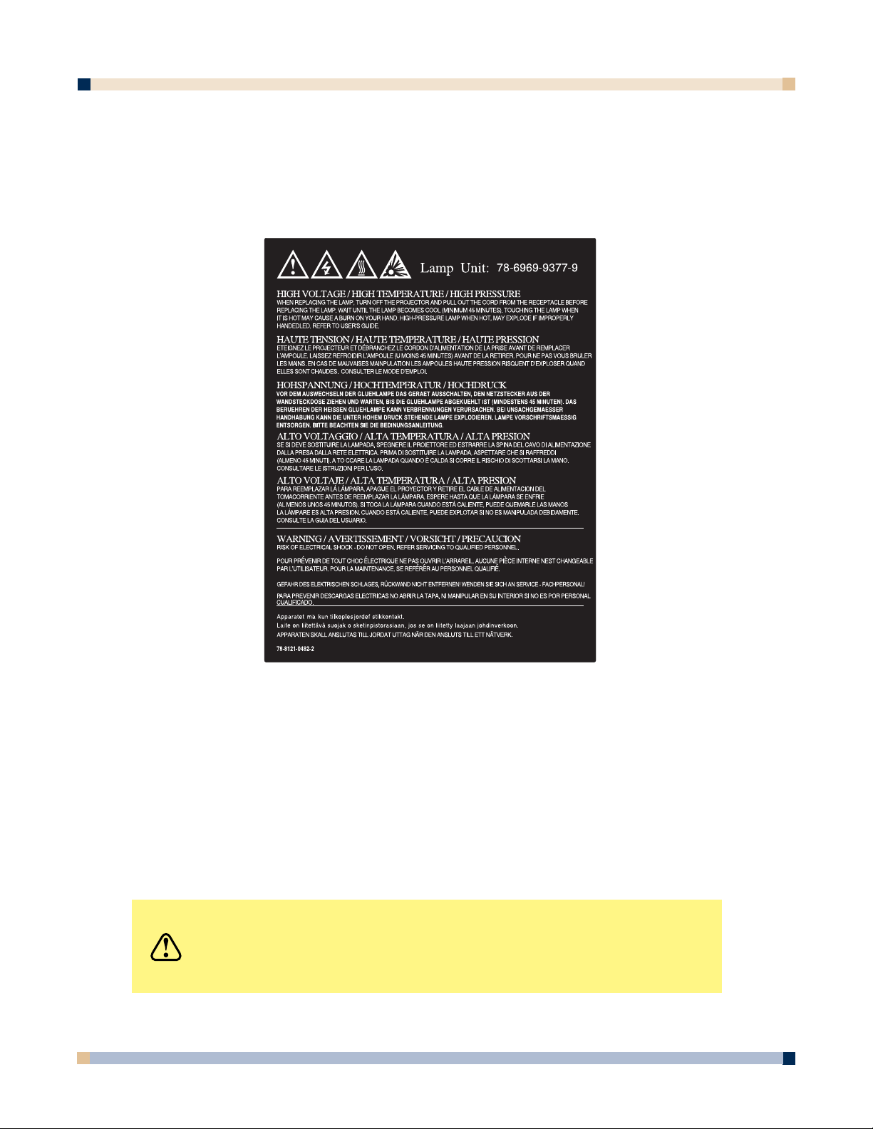
PRODUCT SAFETY LABEL
The following safety label is used on or within the 3M™ Digital WallDisplay to alert you to
this area requiring your attention.
SAVE THESE INSTRUCTIONS
The information contained in this manual will help you operate and maintain your 3M
Digital WallDisplay.
CAUTION
In some countries, the voltage is NOT stable. This appliance
is designed to operate within a range of 100~240 volts, ±10
volts, but it could fail if power drops or surges of ±10 volts
occur. In these high-risk areas, it is recommended to install
a power stabilizer unit.
Page 7

OPERATOR’S GUIDE
3 M™ DIGITAL WALLDISPLAY
7
TRADEMARKS
The 3M logo and 3M are registered trademarks of 3M Company. Vikuiti is a trademark of 3M
Company.
Microsoft, Windows, Windows NT, Word, Excel, PowerPoint, Internet Explorer, and
NetMeeting are either registered trademarks or trademarks of the Microsoft Corporation in the
United States and/or other countries.
IBM is a registered trademark of International Business Machines Corporation.
Apple Macintosh and Apple PowerBook are registered trademarks of Apple Computer, Inc.,
registered in the U.S. and other countries.
Intel and Pentium are registered trademarks of Intel Corporation or its subsidiaries in the U.S.
and other countries.
Digital Light Processing is a trademark or registered trademark of Texas Instruments.
eBeam, e-Beam, eBeam Mouse, eBeam Moderator, eBeam Software, ImagePort and eBeam
Presenter are registered trademarks of Electronics for Imaging, Inc.
Sun and Java are trademarks or registered trademarks of Sun Microsystems, Inc. in the United
States and other countries.
UNIX is a registered trademark in the United States and other countries, licensed exclusively
through X/Open Company Limited.
Palm is a trademark of Palm Computing, Inc. or its subsidiaries.
Netscape and the Netscape N and Ship’s Wheel logos are registered trademarks of Netscape
Communications Corporation in the U.S. and other countries. Navigator and Communicator are
also trademarks of Netscape Communications Corporation and may be registered outside the
U.S.
All other products are trademarks or registered trademarks of their respective companies.
PATENTS
3M Digital WallDisplay is protected by Utility Patent 6,179,426 and Design Patent D442,205.
Other patents pending.
SOFTWARE AND COPYRIGHT LICENSE AGREEMENT
The software in this distribution is copyrighted and licensed by Electronics for Imaging, Inc.
3M DIGITAL WALLDISPLAY TECHNICAL SUPPORT
• 1-800-328-1371
• Web Site: http://www.3M.com/walldisplay
Page 8
3 M™ DIGITAL WALLDISPLAY
OPERATOR’S GUIDE
8
FCC STATEMENT—CLASS A
This device complies with Part 15 of the FCC Rules. Operation is subject to the following
two conditions: (1) this device may not cause harmful interference, and (2) this device must
accept any interference received, including interference that may cause undesired operation.
Instructions to Users
This equipment has been tested and found to comply with the limits for a
Class Adigital device, pursuant to Part 15 of the FCC Rules. These limits
are designed to provide a reasonable protection against harmful interference
when the equipment is operated in a commercial environment. This
equipment generates, uses, and can radiate radio frequency energy and, if
not installed and used in accordance with the instruction manual, may cause
harmful interference to radio communications. Operation of this equipment
in a residential area is likely to cause harmful interference in which case the
user will be required to correct the interference at his own expense.
Notice
This Class Adigital apparatus meets all requirements of the Canadian
Interference-Causing Equipment Regulations.
Cet appareil numérique de la classe Arespecte toutes les exigences du
Règlement sur le matériel brouilleur du Canada.
EEC STATEMENT—CLASS A
This machine was tested against the 89/336/EEC (European Economic Community) for
EMC (Electro Magnetic Compatibility) and fulfills these requirements.
Video Signal Cables
Double shielded coaxial cables (FCC shield cable) must be used, and the
outer shield must be connected to the ground. If normal coaxial cables are
used, the cable must be enclosed in metal pipes or in a similar way to
reduce the interference noise radiation.
Video Inputs
The input signal amplitude must not exceed the specified level.
(See Appendix for these levels.)
WARNING
This is a Class A product. In a domestic environment, this
product may cause radio interference in which case the
user may be required to take adequate measures.
Page 9
OPERATOR’S GUIDE
3 M™ DIGITAL WALLDISPLAY
9
INTRODUCTION
CONTENTS
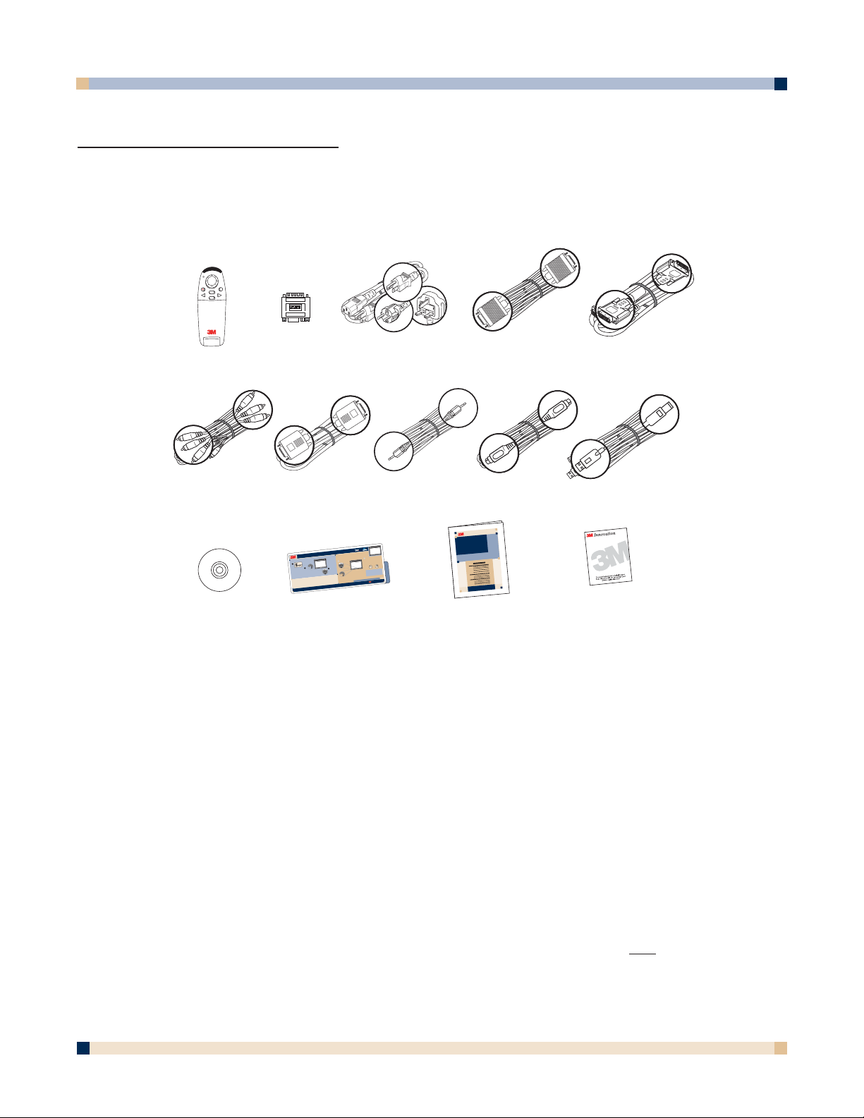
The 3M Digital WallDisplay is shipped with the necessary cables required for standard VCR, PC,
Macintosh or laptop computer connections. Carefully unpack and verify that you have all of the
items shown below. If any are missing, please contact your place of purchase.
OPTIONAL ACCESSORIES
• Vikuiti™ High-Brightness screen • Digital White Board kit
• Accessory Tray/Laptop Shelf • Vikuiti Easy-Erase screen
• Replacement Lamp Kit • Extended warranty
Note: Save the shipping box and packing materials in the event the 3M Digital WallDisplay
should ever need to be moved.
WHAT’S NEXT?
After the 3M Digital WallDisplay has been professionally installed in your meeting room, you are
ready to set it up.
Please read this guide thoroughly before operating your new 3M Digital WallDisplay.
Be sure to check our web site
(www.3M.com/walldisplay) regularly for updates and supplemental
information. On the CD-ROM, you can link directly to the web site by clicking here
or on
“3M
Innovation” in the lower right corner of the Main Menu.
POWER
R
MOUSE
MENU
INPUT
BLANK
MUTE
ON
OFF
1 2 3 4 5 6
S
H
U
T
D
O
W
N
S
T
A
R
T
U
P
1
2
3
P
r
e
s
s
t
h
e
M
a
s
t
e
r
P
o
w
e
r
S
w
i
t
c
h
.
(
L
e
a
v
e
t
h
i
s
s
w
i
t
c
h
O
n
.
)
T
h
e
O
n
/
O
f
f
b
u
t
t
o
n
w
i
l
l
t
u
r
n
a
m
b
e
r
i
n
a
p
p
r
o
x
i
m
a
t
e
l
y
5
se
c
o
n
d
s
.
P
l
u
g
p
o
w
e
r
c
o
r
d
i
n
t
o
o
u
t
l
e
t
.
P
r
e
s
s
t
h
e
O
n
/
O
f
f
b
u
t
t
o
n
.
•
A
f
t
e
r
p
r
e
s
s
i
n
g
,
t
h
e
O
n
/
O
f
f
b
u
t
t
o
n
b
l
i
n
k
s
g
r
e
e
n
,
t
h
e
n
s
t
a
y
s
g
r
e
e
n
.
•
T
h
e
p
r
o
j
e
c
t
i
o
n
a
r
m
e
x
t
e
n
d
s
o
u
t
fr
o
m
t
h
e
t
o
p
o
f
W
a
l
l
D
i
s
p
l
a
y
.
•
T
h
e
f
a
n
m
o
t
o
r
s
t
a
r
t
s
.
•
T
h
e
l
a
m
p
c
o
m
e
s
o
n
.
(
A
l
l
o
w
a
p
p
r
o
x
i
m
a
t
e
l
y
1
m
i
n
u
t
e
f
o
r
f
u
l
l
i
l
l
u
m
i
n
a
t
i
o
n
.
)
W
A
L
L
D
I
S
P
L
A
Y
Q
U
I
C
K
S
T
A
R
T
G
U
I
D
E
2
0
0
:
0
5
:
0
0
0
0
:
0
0
:
0
0
T
h
e
O
n
/
O
f
f
b
u
t
t
o
n
b
l
i
n
k
s
r
e
d
f
o
r
3
0
s
e
c
o
n
d
s
.
T
h
e
p
r
o
j
e
c
t
i
o
n
a
r
m
c
l
o
s
e
s
.
T
h
e
f
a
n
r
u
n
s
f
o
r
5
m
i
n
u
t
e
s
.
“
W
h
e
r
e
v
e
r
t
h
e
r
e
'
s
a
g
r
e
a
t
m
e
e
t
i
n
g
,
y
o
u
’
l
l
f
i
n
d
3
M
.
”
(
™
)
w
w
w
.
3
M
.
c
o
m
/
w
a
l
ld
i
s
p
la
y
Innovation
N
o
t
e
:
A
f
t
e
r
t
h
e
O
n
/
O
f
f
b
u
t
t
o
n
i
s
p
r
e
s
s
e
d
,
t
h
e
u
n
i
t
w
i
l
l
n
o
t
r
e
s
p
o
n
d
t
o
a
n
y
o
t
h
e
r
c
o
m
m
a
n
d
s
f
o
r
3
0
s
e
c
o
n
d
s
.
1
(
L
e
a
v
e
t
h
e
M
a
s
t
e
r
P
o
w
e
r
S
w
i
t
c
h
t
u
r
n
e
d
O
n
.
)
P
r
e
s
s
t
h
e
O
n
/
O
f
f
b
u
t
t
o
n
.
Q
U
I
C
K
S
T
A
R
T
G
U
I
D
E
WAL
L DISPLAY
PRODUCT
AND SAFETY
INFORMATION
Remote Control
(with batteries)
Mac
adapter
Power Cable
(US, UK, Euro)
Serial
Mouse Cable
DVI-D Cable
3-Conductor
Video/Audio Cable
VGA Cable
PC Audio
Cable
S-Video
Cable
USB
Cable
Operator’s Guide
(CD-ROM)
Quick Start Guide Product Safety
Guide
Product Registration
Card
Page 10
3 M™ DIGITAL WALLDISPLAY
OPERATOR’S GUIDE
10
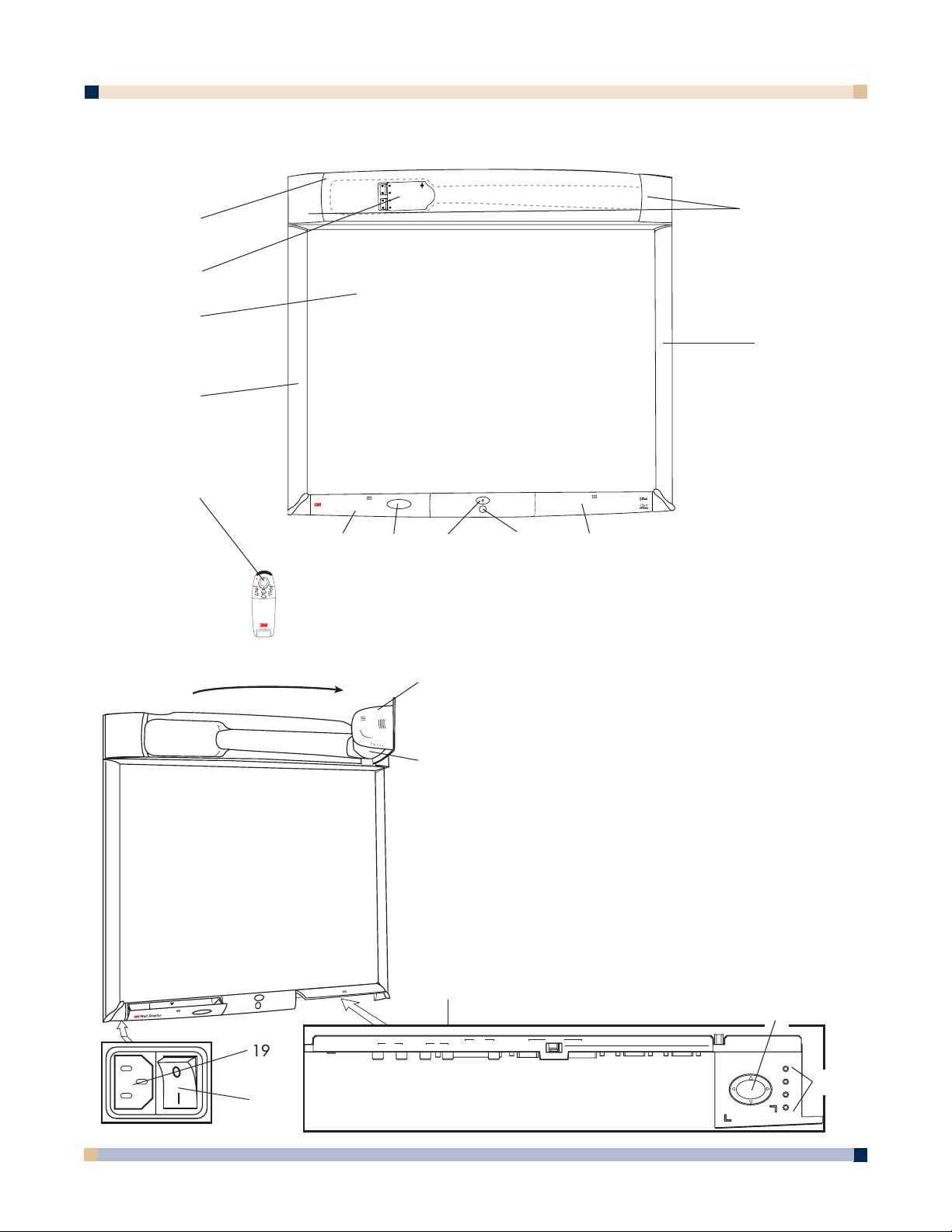
PART IDENTIFICATION
1
3
5
11
2
4
12
6
7 8 9
10
13
14
15
16
17
18
1. Facade
2. Lamp Housing Door (behind facade)
3. Projection Screen
4. Left Bezel
5. Remote Control Unit
6. Storage Door
7. Storage Door Window
8. On/Off Button
9. Infrared Remote Sensor
10. Connection Panel Door
11. Right Bezel
12. Speakers
13. Projection Head
14. Projection Arm
15. Connection Panel
16. Menu Keypad
17. Status LED Indicators
18. Master Power Switch
19. AC Power Cord Socket
19
R
POWER
MOUSE
MENU
MUTE
BLANK
INPUT
Wall Display
from 3M
S-VIDEO RCA VGA DVI-D
SERIAL
MOUSE
RS-232AUDIO VIDEO COMPUTERROW
1
2
3
MENU KEYPAD
4
PC
USB
AUDIO
MOUSE
1
2 (THIS ROW FOR DIGITAL WHITEBOARD OPTION ONLY) PRINTER COMPUTER
OUT
IN
Page 11

11
OPERATOR’S GUIDE
3 M™ DIGITAL WALLDISPLAY
3M DIGITAL WALLDISPLAY FEATURES
The 3M Digital WallDisplay combines the following features into one sleek, sophisticated
package.
• Full connectivity for computer or video presentations
• Large 60˝ diagonal screen
• 4:3 screen aspect ratio matches business applications and viewing data
• Flat screen allows extra wide (up to 170°) viewing angles
• Projection arm position guarantees image is in focus every time
• Allows presenter to move without blocking image
• Built-in, powerful stereo speaker system
• Single button operation
• Hand-held remote control for most functions
• Ideaboard option
- allows notes and writing directly on screen for productive brainstorming
- digital image capture for sharing files or storing information
- print content directly from attached printer
- easy to replace projection screens
- the Vikuiti™ Dry-Erase screen allows the 3M Digital WallDisplay to double as a
dry-erase board
Page 12
3 M™ DIGITAL WALLDISPLAY
OPERATOR’S GUIDE
12
SYSTEM SETUP
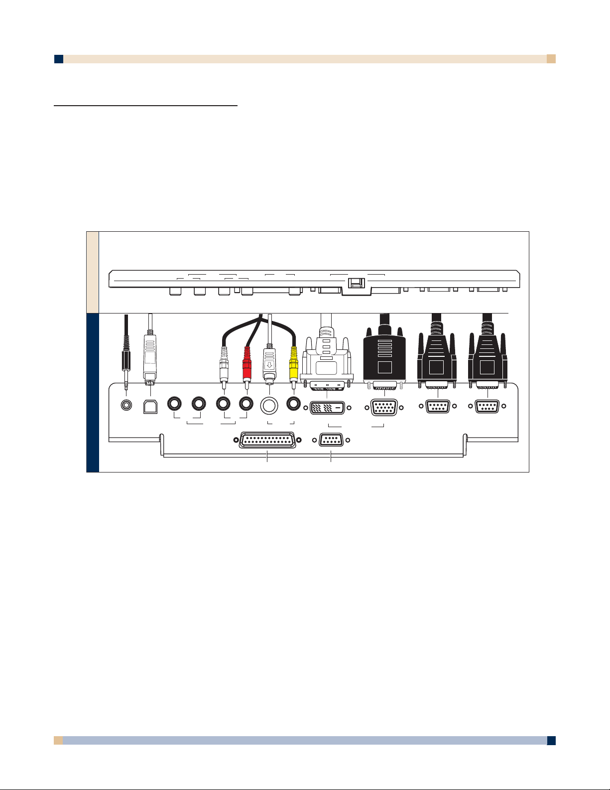
CONNECTING TO VARIOUS EQUIPMENT
It only takes a few minutes to connect the 3M™ Digital WallDisplay to your computer, VCR, DVD
player, video conference unit, or other devices.
The connection panel is located underneath the bottom right corner of the 3M Digital WallDisplay,
under the Connection Panel Door. Press and release door to access connection panel.
Note: Use the enclosed cables to ensure image and audio quality. Substituting cables of lesser
quality may result in poor image quality or audio noise.
PC Audio Connects to the computer’s audio output and provides audio for VGA
and DVI-D (Digital Visual Interface - Digital only) inputs.
USB Mouse Connects to the computer’s USB port and provides wireless mouse
control using the 3M Digital WallDisplay remote control Disk Pad button.
Audio Out Connects to an external audio amplifier and provides audio from the
active audio source.
Audio In Connects to the audio output of a video device (e.g. VCR or DVD),
and provides audio for both S-Video and RCA video inputs.
S-Video Connects to an S-Video output signal.
RCA Video Connects to an audio/video device.
DVI-D Connects to a computer that supports the DVI-D interface.
VGA Connects to the RGB Out port or monitor of a computer.
Serial Mouse Connects to a computer’s 9-pin serial port and provides wireless mouse
control using the 3M Digital WallDisplay remote control
Disk Pad button.
RS-232 Connects to a control device’s serial port and provides control of the 3M
Digital WallDisplay using RS-232C protocol and the specified serial
commands.
PC
USB
AUDIO
1
FRONT OF PANEL
MOUSE
2 (THIS ROW FOR DIGITAL WHITEBOARD OPTION ONLY) PRINTER COMPUTER
OUT
IN
S-VIDEO RCA VGADVI-D
SERIAL
MOUSE
RS-232AUDIO VIDEO COMPUTERROW
BOTTOM OF PANEL
PC
Audio
USB
Mouse
Out S-Video RCA
(This row for Digital
Whiteboard option only)
Audio
In
Printer
Video
Computer
Computer
VGADVI-D
Serial
Mouse
RS-232
Page 13
13
OPERATOR’S GUIDE
3 M™ DIGITAL WALLDISPLAY
OPERATION
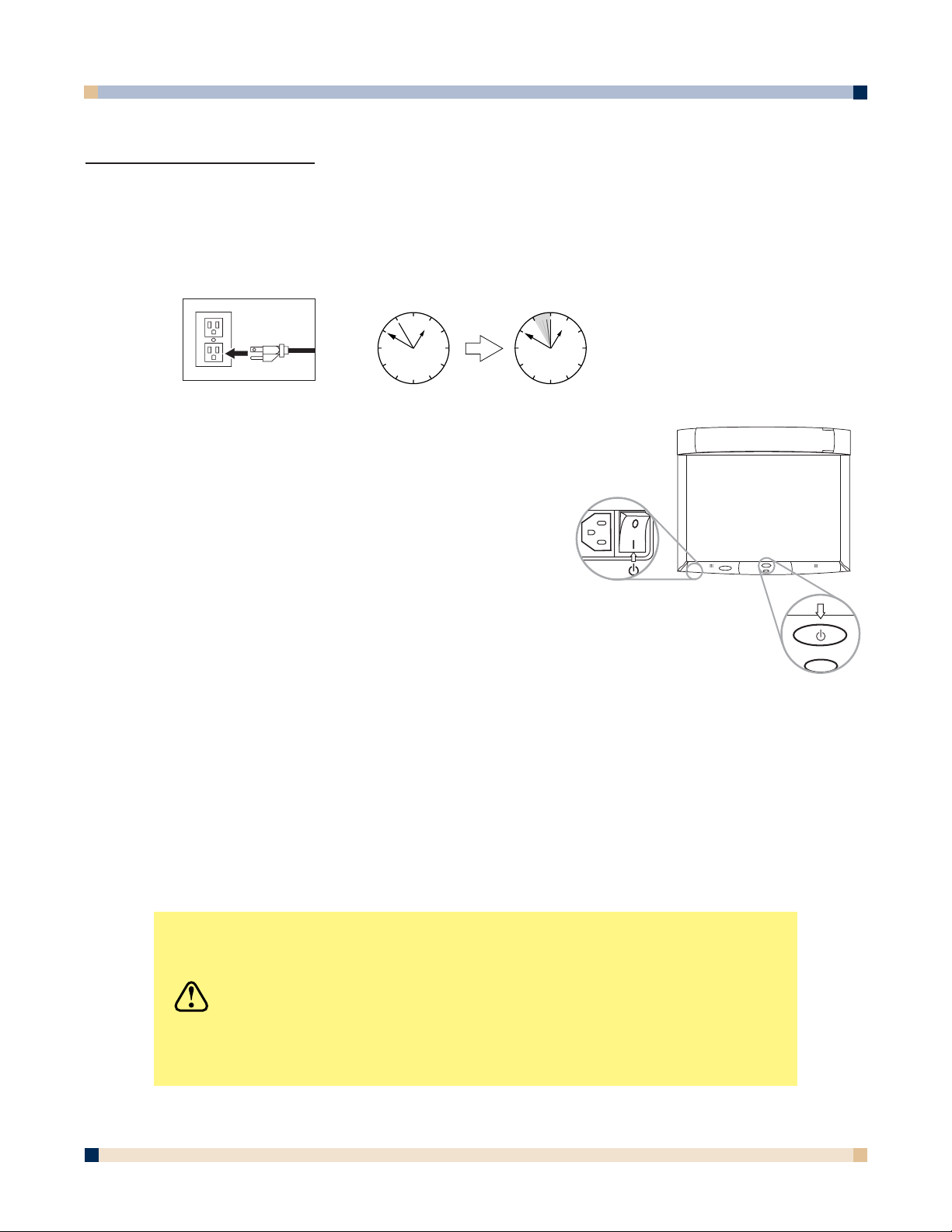
STARTUP
1. Plug power cord into wall socket. Wait five (5) seconds before pressing the Master
Power Switch.
2. Flip on the Master Power Switch beneath the lower
left corner of the 3M Digital WallDisplay, near the
3M label. This should stay on at all times. Now the
3M Digital WallDisplay is in standby mode. The large
oval
On/Off Button will be backlit amber after several
seconds.
3. Press the
On/Off Button in the center of the lower
front panel. The projection arm will extend outward
from its housing at the top of the 3M Digital WallDisplay
unit for several seconds. Do not block its movement.
• The
On/Off Button on the front of the
machine will blink amber during the warm-up
and projection arm extension.
4. When the projection arm is fully extended, the lamp will turn on automatically. It will
reach full illumination in approximately 60 seconds. The
On/Off Button should then be
backlit green.
CAUTION
• The 3M Digital WallDisplay’s projection arm is motorized.
Do not block its movement or force it to move while the
3M Digital WallDisplay is in operation.
• Do not look directly into the 3M Digital WallDisplay
projection lens. The light from the lens may cause
damage to eyes.
00:00:0500:00:00
Page 14
3 M™ DIGITAL WALLDISPLAY
OPERATOR’S GUIDE
14
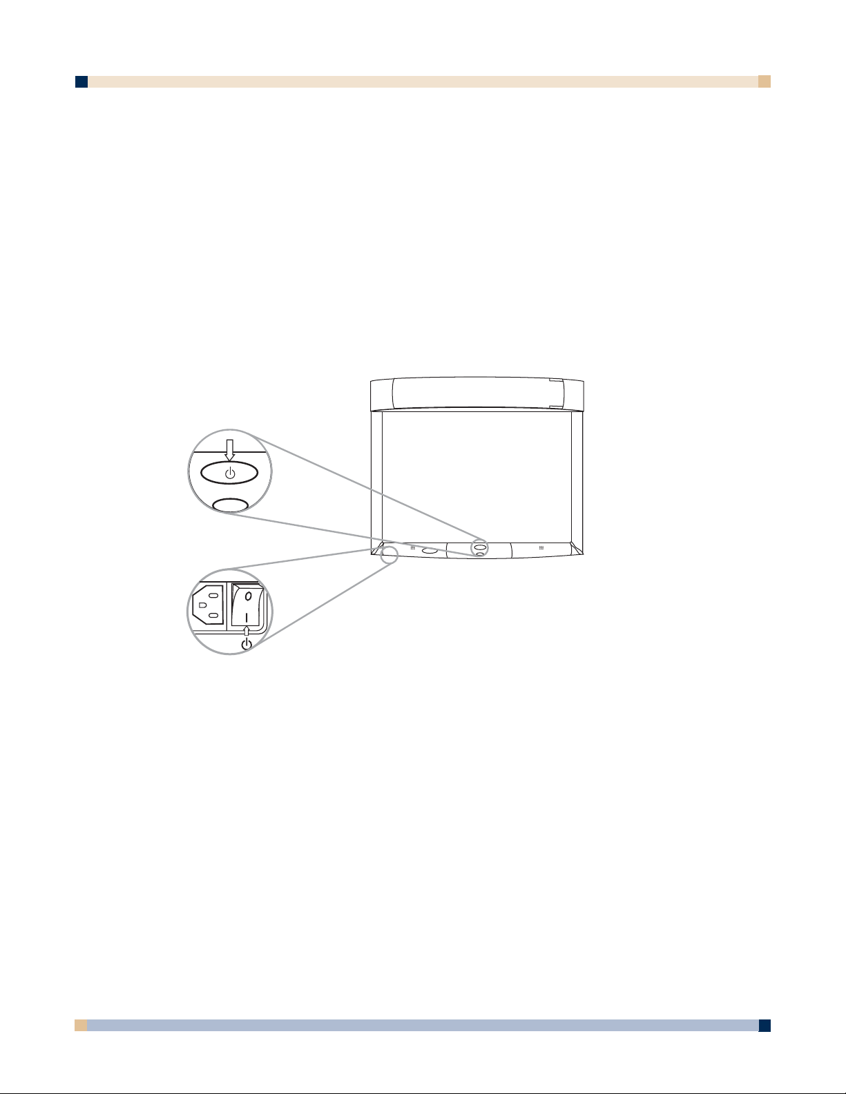
SHUTDOWN
Press the On/Off Button on the bottom center panel of the 3M™ Digital WallDisplay unit.
The lamp will turn off and the projector arm will return to its housing. The On/Off
Button
will flash amber.
Note: There is a 30-second reset period before the On/Off Button will function again.
The fan will continue to run for approximately five minutes to cool the unit.
Note: If the 3M Digital WallDisplay will not be moved or disconnected, leave the Master
Power Switch
on for your convenience.
Do not turn off the
Master Power Switch or unplug the power cord before pressing
the On/Off Button. After the On/Off Button is pressed, the fan continues for
approximately five minutes to cool the 3M Digital WallDisplay.
Page 15
OPERATOR’S GUIDE
3 M™ DIGITAL WALLDISPLAY
15
REMOTE CONTROL UNIT
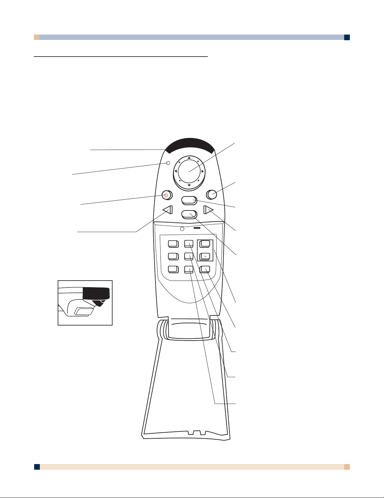
FEATURES
The remote control sensor is on the front lower panel of the 3M Digital WallDisplay unit.
The distance between the sensor and remote control must be shorter than 4 meters (13 feet).
The remote control unit has two keypads. The Forward keypad is above the flip-top cover.
The Rear keypad is beneath the cover. The
Trigger Button is underneath the front IR Sensor
of the remote control unit and can be pressed easily with the index finger.
IR SENSOR
Transmits infrared signals to 3M
Digital WallDisplay unit.
DISK PAD
Press to control the computer’s
mouse, navigate the menu
system, or control the Pointer or
Reveal functions.
R MOUSE
Press for right-mouse-button
function in mouse mode.
MENU
Press to display onscreen
menu system.
BLANK
Press to turn the screenblanking function on/off.
INPUT
Press to change source of
input.
VOLUME
Press to adjust the speaker
and Audio Out sound level.
TIMER
Press to turn on/off display of
countdown timer.
FREEZE
Press to turn the still-mode
function on/off.
REVEAL
Press to uncover part of the
screen from top to bottom or
from left to right.
LED
Indicates that remote control unit
is transmitting signal.
POWER
Press to turn 3M Digital
WallDisplay on/off.
MUTE
Press to turn the audio (speaker)
POINTER
Press to turn the pointing
function on/off.
FORWARD KEYPAD
REAR KEYPAD
TRIGGER BUTTON
Press for left-mouse
button functions.
POWER
MUTE
MENU
INPUT
POINTER
FREEZE
REVEAL TIMER
BLANK
VOLUME
R
MOUSE
+
Page 16

3 M™ DIGITAL WALLDISPLAY
OPERATOR’S GUIDE
16
FORWARD KEYPAD
Power
Press to turn the 3M™ Digital WallDisplay on/off. When power is turned on, the 3M Digital
WallDisplay will automatically extend the projection arm and ignite the lamp.
Mute
Press to temporarily turn off the sound. Press again or press the Volume + or - buttons to restore
sound.
Disk Pad
Press to:
• control the computer ’s mouse when using the Mouse function.
• select menu items and adjust values in the onscreen menu system.
• control the Pointer position while using the Pointer function.
• control the path of the Reveal function.
While using the onscreen menu system or Pointer function, the computer Mouse function is
temporarily disabled. To regain computer mouse control, turn off the current function or the
onscreen menu system.
Note: The USB or serial mouse cable must be connected between the 3M Digital
WallDisplay and the computer when using Mouse mode.
R Mouse
Acts as the right-mouse-button when the mouse function is active.
Menu
Press to display the onscreen menu system or to cancel display.
Blank
Press to make the screen go blank. Press again to return to normal display function.
Input
Press to change the source of input for 3M Digital WallDisplay. The Input button cycles
between Computer, DVI, S-Video, Composite Video, and No Signal.
Page 17

OPERATOR’S GUIDE
3 M™ DIGITAL WALLDISPLAY
17
REAR KEYPAD
Pointer
Press to turn the pointing function on/off. A red dot will appear on the screen. The dot can
be controlled by pressing the arrows on the Disk Pad.
Volume
Press the + button to increase or the - button to decrease the speaker loudness level. When
the audio is muted, the Volume + or - buttons will also cancel the Mute function.
Timer
Press to turn the timing function on/off. The timer will display on the screen and begin to
count down. To change the Timer value, refer to the
On Scrn Timer sub-menu in the Tools
menu.
Freeze
A moving image can be stilled or ‘frozen’ when the Freeze button is pressed. To release the
Freeze function, press the Freeze button again.
Reveal
Press to turn the screen-reveal function on/off. Press the Disk Pad in the desired reveal
direction (e.g. press down to reveal from the top down, etc.).
Trigger Button
On the underside of the remote control unit, beneath the IR sensor, press button for leftmouse-button functions.
Page 18
3 M™ DIGITAL WALLDISPLAY
OPERATOR’S GUIDE
18
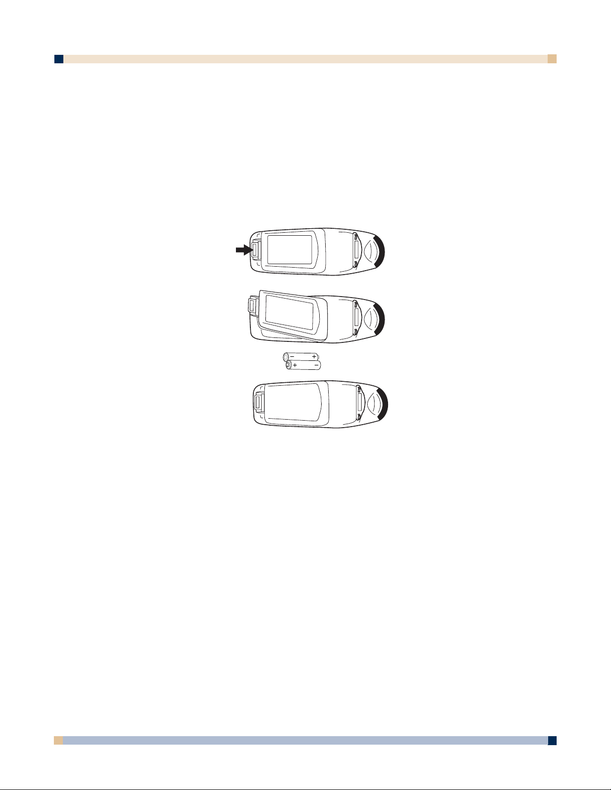
INSTALLING OR REPLACING BATTERIES
1. Push and slide the battery compartment tab in the direction shown, then lift it off.
2. Install two AAA batteries as indicated by the diagram inside the compartment.
3. Snap the battery compartment cover back on.
Note: Avoid excessive heat and humidity.
Do not mix old and new batteries or different types of batteries.
Page 19

OPERATOR’S GUIDE
3 M™ DIGITAL WALLDISPLAY
19
MENU SYSTEM
MENU NAVIGATION
Most adjustments and settings are available in the main menu and sub-menus. To navigate
and make adjustments, use the 3M Digital WallDisplay’s
Menu Keypad button or the
remote control’s
Menu and Disk Pad buttons.
COLORFUL—BRIGHT SLIDER
The Colorful—Bright slider adjusts the brightness, contrast, and color saturation levels
simultaneously. Move the slider toward
Colorful to achieve maximum color saturation
and contrast. Move the slider toward Bright to achieve maximum brightness.
To adjust the
Colorful—Bright slider:
1. Open the menu system by pressing the
remote control Menu button or any arrow on
the
Menu Keypad.
2. Select the Colorful—Bright slider by
pressing the up or down arrows on the
remote control
Disk Pad or Menu Keypad.
3. Move the slider by pressing the left or right
arrow of the Disk Pad or Menu Keypad.
4. Close the menu system by pressing the
Menu button or scrolling to Exit and
selecting it with the right arrow of the
Menu Keypad.
1
2
3
MENU KEYPAD
4
Page 20
3 M™ DIGITAL WALLDISPLAY
OPERATOR’S GUIDE
20
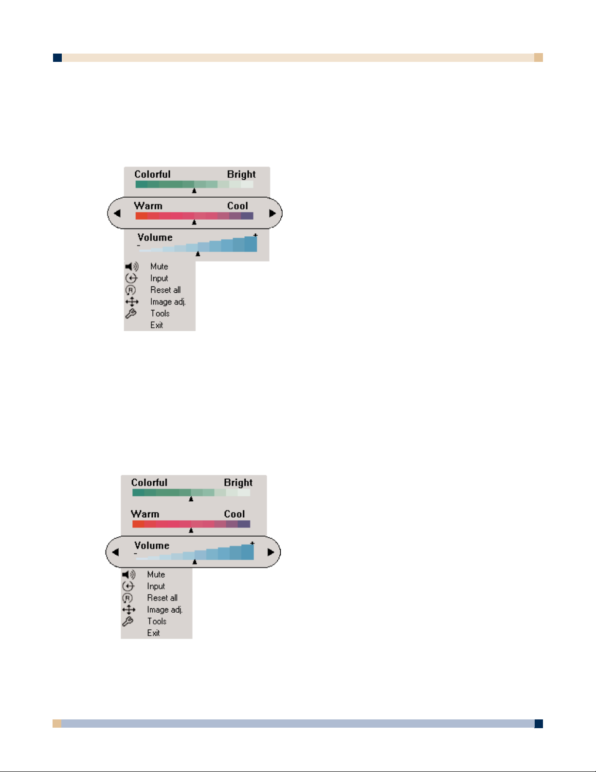
WARM—COOL SLIDER
The Warm—Cool slider adjusts the color temperature. Move the slider toward Warm to
achieve warmer, more reddish images. Move the slider toward
Cool to achieve cooler, more
bluish images.
To adjust the
Warm—Cool slider:
VOLUME SLIDER
The Volume slider adjusts the speaker and audio output sound level. Move the slider toward
the right to increase the sound. Move the slider toward the left to decrease the sound.
To adjust the
Volume slider:
1. Open the menu system by pressing the
remote control Menu button or any arrow on
the
Menu Keypad.
2. Select the Warm—Cool slider by pressing
the up or down arrows on the remote control
Disk Pad or Menu Keypad.
3. Move the slider by pressing the left or right
arrow of the
Disk Pad or Menu Keypad.
4. Close the menu system by pressing the
Menu button or scrolling to Exit and
selecting it with the right arrow of the
Menu Keypad.
1. Open the menu system by pressing the
remote control Menu button or any arrow on
the Menu Keypad.
2. Select the Volume slider by pressing the up
or down arrows on the remote control
Disk Pad or Menu Keypad.
3. Move the slider by pressing the left or right
arrow of the Disk Pad or Menu Keypad.
4. Close the menu system by pressing the
Menu button or scrolling to Exit and
selecting it with the right arrow of the
Menu Keypad.
Page 21
21
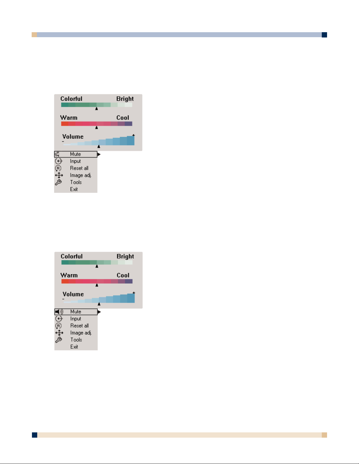
MUTE MENU FUNCTION
The Mute menu function turns the sound on and off.
To turn the
Mute menu function on:
To turn the
Mute menu function off:
OPERATOR’S GUIDE
3 M™ DIGITAL WALLDISPLAY
Mute function ON
Mute function OFF
1. Open the menu system by pressing the remote
control
Menu button or any arrow on the Menu
Keypad.
2. Select the Mute menu function by pressing the up
or down arrows on the remote control
Disk Pad
or Menu Keypad.
3. Turn the Mute function on by pressing the left or
right arrow of the
Disk Pad or Menu Keypad.
The sound will turn off.
4. Close the menu system by pressing the
Menu
button or scrolling to Exit and selecting it with
the right arrow of the Menu Keypad.
1. Open the menu system by pressing the remote
control
Menu button or any arrow on the Menu
Keypad.
2. Select the Mute menu function by pressing the up
or down arrows on the remote control
Disk Pad
or Menu Keypad.
3. Turn the Mute function off by pressing the left or
right arrow of the
Disk Pad or Menu Keypad.
The sound will turn on.
4. Close the menu system by pressing the
Menu
button or scrolling to Exit and selecting it with
the right arrow of the Menu Keypad.
Page 22
3 M™ DIGITAL WALLDISPLAY
OPERATOR’S GUIDE
22
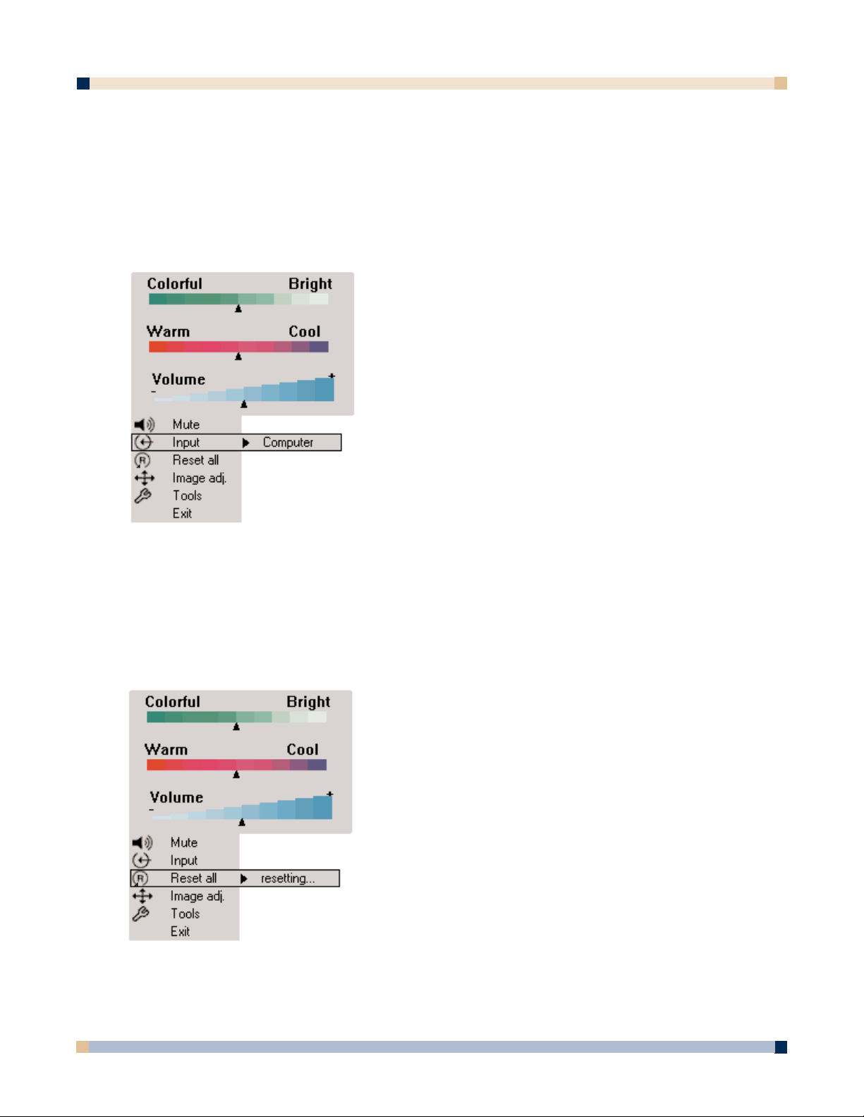
INPUT SELECT MENU
The Input Select menu defines the displayed video source. When Input Select menu is selected,
the current video source is shown. The
Input options are: Computer (VGA Input), DVI-D, S-Video,
Comp. Video (RCA Video Input), and No Signal. An Input option is available to select when an
active video source is connected to the 3M™ Digital WallDisplay input connection.
To set the
Input Select menu:
RESET ALL MENU
The Reset All menu function sets all menu settings to their default settings.
To turn the
Reset All menu function on:
1. Open the menu system by pressing the remote
control
Menu button or any arrow on the Menu
Keypad.
2. Select the Input Select menu function by
pressing the up or down arrows on the remote
control
Disk Pad or Menu Keypad.
3. Press the right arrow of the Disk Pad or Menu
Keypad
repeatedly until the desired input option
is shown.
4. Activate the input option by pressing the left
arrow of the
Disk Pad or Menu Keypad.
5. Close the menu system by pressing the
Menu
button or scrolling to Exit and selecting it with
the right arrow of the Menu Keypad.
1. Open the menu system by pressing the remote
control
Menu button or any arrow on the Menu
Keypad.
2. Select the Reset All menu function by pressing
the up or down arrows on the remote control Disk
Pad or Menu Keypad.
3. To activate the Reset All function, press the right
arrow of the Disk Pad or Menu Keypad.
4. Close the menu system by pressing the Menu
button or scrolling to Exit and selecting it with
the right arrow of the Menu Keypad.
Page 23
23
OPERATOR’S GUIDE
3 M™ DIGITAL WALLDISPLAY
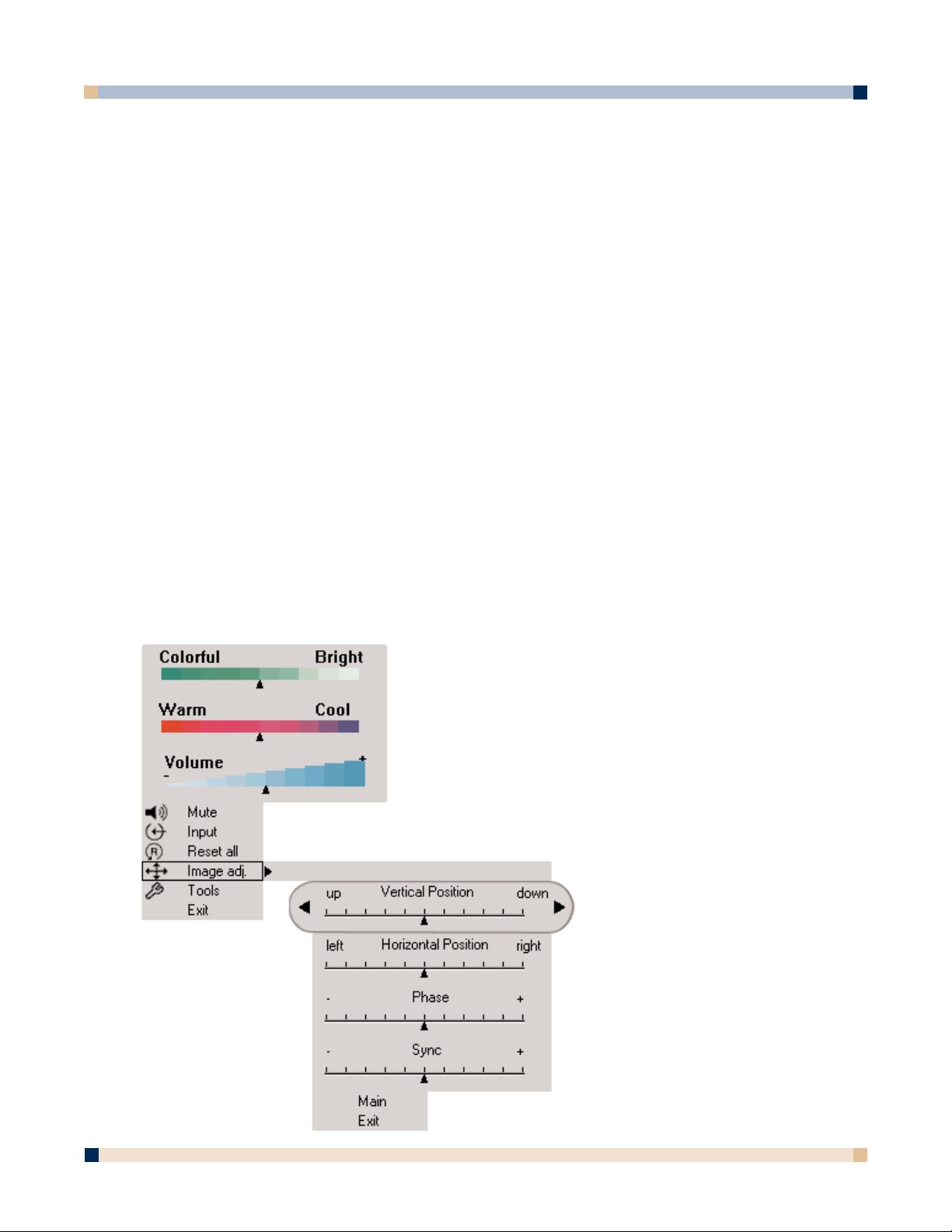
IMAGE ADJ SUB-MENU
The Image Adjustment sub-menu adjusts the projected image settings for the VGA and
DVI-D inputs. Use the
Vertical Position and Horizontal Position sliders to reposition an
image if portions are not visible. Use the Phase and Sync sliders to eliminate vertical
banding and noise.
Vertical Position Adjusts the vertical position of the projected image.
Horizontal Position Adjusts the horizontal position of the projected image.
Phase Adjusts the pixel sampling. Use this to reduce image noise
and flicker.
Sync Adjusts the expected pixel number in a single video line.
Use this to eliminate banding.
Main Returns to main menu.
Exit Leaves the menu system.
To open the
Image Adj submenu:
1. Open the menu system by pressing the remote control Menu button or any arrow on the
Menu Keypad.
2. Select the Image Adj sub-menu by pressing the up or down arrows on the remote control
Disk Pad or Menu Keypad.
3. To open the Image Adj sub-menu, press the right
arrow of the Disk Pad or Menu Keypad.
4. Scroll to the desired slider and move it to the
right or left as needed.
5. Close the menu system by pressing the
Menu
button or scrolling to Exit and selecting it with
the left or right arrow of the
Menu Keypad.
To return to the main menu, select Main and press
the left or right arrow of the Disk Pad or Menu
Keypad.
Page 24
3 M™ DIGITAL WALLDISPLAY
OPERATOR’S GUIDE
24
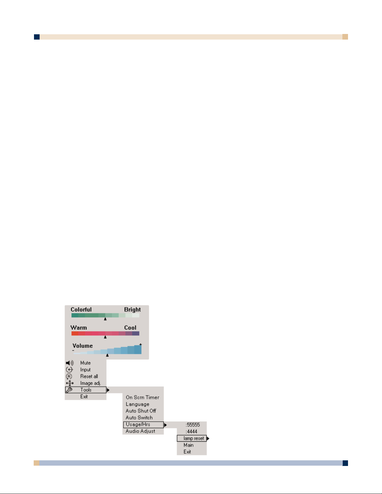
TOOLS SUB-MENU
The Tools sub-menu provides access to the following settings and tools:
Onscreen Timer Allows you to set a timer and display it onscreen.
Language Selects which language to use for onscreen commands. (Default
language is English.) It cycles between English, German, Spanish,
Italian, and French.
Auto Shutoff Will automatically turn off the 3M™ Digital WallDisplay within the
time desired. (Default time is 45 minutes.)
Auto Switch When an input source is lost or disconnected, Auto Switch automat-
ically detects and switches to the next available input source. When
Auto Switch is disabled, press the
Input button on the remote
control to select the next available input source.
Usage/Hrs Displays and/or resets 3M Digital WallDisplay’s and lamp’s
operating time, in number of hours.
Audio Adjust Allows you to adjust the bass and treble.
To open the
Tools sub-menu:
1. Open the menu system by pressing the remote control Menu button or any arrow on the Menu
Keypad.
2. Select the Tools sub-menu by pressing the up or down arrows on the remote control Disk
Pad or Menu Keypad.
3. To open the Tools sub-menu, press the right arrow of the Disk Pad or Menu Keypad.
4. Scroll to the desired item and adjust as needed.
5. Close the menu system by pressing the
Menu button or scrolling to Exit and selecting it with
the right arrow of the Menu Keypad.
To return to the main menu, select Main and press the left or
right arrow of the
Disk Pad or Menu Keypad.
Page 25
OPERATOR’S GUIDE
3 M™ DIGITAL WALLDISPLAY
25
MAINTENANCE
GENERAL MAINTENANCE
For general cleaning of the screen and exterior of the 3M Digital WallDisplay, use a damp
cloth or dry cleaning cloth such as the 3M High Performance Cleaning Cloth.
Standard dry-erase cleaners may be used on the dry-eraseable screens, such as Sanford
®
Expo®Whiteboard Cleaner. Do not use other spray cleaners or solvents on any part of the
3M Digital WallDisplay.
LAMP USAGE
Use and Replacement of Lamp
The 3M Digital WallDisplay lamp has a normal operating time of approximately 2000
hours, called the lamp life. After the lamp has been operating for 1900 hours or longer, the
following messages will appear on the screen for the first three minutes of operation. When
this happens, turn off the 3M Digital WallDisplay and replace the lamp with a new one.
Using an old lamp in the 3M Digital WallDisplay could cause a malfunction.
Onscreen Lamp Messages
PLEASE CHANGE THE LAMP
The lamp has been in use for 1900 hours and needs to be changed. After replacing the lamp,
reset the lamp timer.
THERE ARE 20 HOURS OF LAMP LIFE REMAINING
The lamp has been in use for 1980 hours, and the power will turn off after 20 more hours.
After replacing the lamp, reset the lamp timer.
PLEASE CHANGE THE LAMP
THE WALLDISPLAY WILL SHUT OFF IN 10 MINUTES
AFTER REPLACING LAMP, RESET THE LAMP TIMER
The lamp has been in use for more than 2000 hours, and the power will automatically turn
off after 10 minutes. After replacing the lamp, reset the lamp timer.
All of these messages will display for no longer than three minutes, but each will display
whenever you turn the lamp on again, until the lamp is replaced.
For lamp-changing instructions, please refer to the next page.
Page 26

3 M™ DIGITAL WALLDISPLAY
OPERATOR’S GUIDE
26
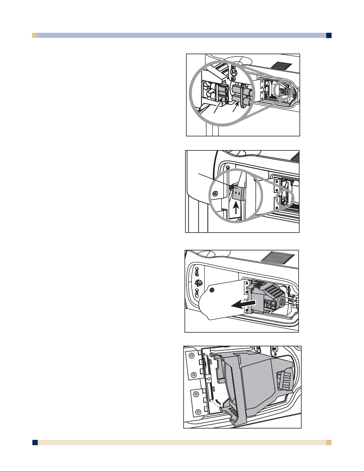
LAMP REPLACEMENT
1. Turn the power off and disconnect the power cord from the outlet.
2. Allow approximately 45 minutes for the lamp to cool, if necessary.
3. There are two indentations behind the top
of the facade, near each end. Grasp facade
plate at each indentation and pull down to
snap off.
4. Loosen the self-contained screw at the
upper righthand corner of the lamp housing
door with a standard screwdriver.
5. Two black wires connect to the lamp
cartridge by a black plastic receptacle on
the right side of the lamp cartridge.
WARNING
To reduce the risk of electrical shock, always turn off the
3M™ Digital WallDisplay unit and disconnect power cord
before changing lamp.
Facade
Lamp
Receptacle
Black wires
Page 27
OPERATOR’S GUIDE
3 M™ DIGITAL WALLDISPLAY
27
5a. Hold down this receptacle with your left
thumb and (5b) pull connectors out of the
receptacle with other hand.
6. Push up the metal lever on the lower left
side of the lamp cartridge.
7. Grasp the lamp cartridge and pull it
straight back out of the lamp compartment.
8. Keep the left edges of the new lamp
cartridge aligned with the lamp
compartment’s grooves and slide the
cartridge smoothly into place.
Lever
5a
5b
Page 28

28
9. Push down the metal lever on the left side of the lamp cartridge.
10. Reconnect black wires to the receptacle.
11. Close the lamp housing door and tighten the screw.
12. Align the slots and tabs of the right side of the
facade and projection arm as shown, then snap
firmly into place.
13. Align the slots and tabs of the left side of the
facade and projection head as shown, then snap
firmly into place.
Note: You must hear or feel a distinctive snap to
ensure facade is securely attached.
Whenever the lamp is replaced, please reset the total lamp operating time. (Refer to next page.)
OPERATOR’S GUIDE
3 M™ DIGITAL WALLDISPLAY
CAUTION
•To reduce the risk of cuts to fingers and/or decreased image
quality by touching the lens, do not insert hand into the empty
lamp compartment.
• This lamp contains mercury. Consult your local hazardous
waste regulations and dispose of this lamp properly.
•Apotential hazard may exist in the rare case of lamp rupture.
Please have a 3M™ Digital WallDisplay dealer replace a ruptured
lamp.
•The lamp is extremely hot during normal operation. Before
replacing the lamp, wait at least 45 minutes after last operation.
• Do not loosen any screws except those mentioned in the lamp
replacement instructions.
Page 29

OPERATOR’S GUIDE
3 M™ DIGITAL WALLDISPLAY
29
RESETTING LAMP HOURS
Please do the following within 10 minutes of turning power on after you replace the lamp.
1. Press the
Menu Keypad or the Menu button on the remote control and use the
Disk Pad to scroll down to the Tools menu.
2. In the
Tools menu, scroll down the pop-up list to Usage/Hrs to display the total
operating time of the lamp.
3. Select Lamp Reset from the next pop-up list.
4. Select Exit.
Note: Do not reset the lamp hours if the lamp cartridge was not changed. This can
damage internal components.
Page 30

3 M™ DIGITAL WALLDISPLAY
OPERATOR’S GUIDE
30
REPLACING PROJECTION SCREEN
Replacing the 3M™ Digital WallDisplay screen is very simple.
1. Turn off the 3M Digital WallDisplay and disconnect the power cord from the wall
outlet.
2. Remove either the right or left side bezel. There are two ways to remove it. Either
snap it off or insert a screwdriver into the notch located on the sides of each
bezel, near the top. The bezel will easily snap on and off for screen replacement.
3. Slide the screen straight out of the open side. Be sure to allow approximately 4 feet
of clear space on either side of the 3M Digital WallDisplay to do this.
4. Insert new screen into the open side and slide into place.
5. Snap bezel back into place.
Note: If you have the 3M Digital WallDisplay with the Ideaboard option, remove the
bezel and screen from the right side only.
Page 31

31
OPERATOR’S GUIDE
3 M™ DIGITAL WALLDISPLAY
3M DIGITAL WALLDISPLAY WITH IDEABOARD
3M Digital WallDisplay with Ideaboard is the 3M Digital WallDisplay unit upgraded with the
Digital White Board option.
If you have the 3M Digital WallDisplay with Ideaboard option, this section will show you how
to set it up and use it.
The Digital White Board option kit contains the following items:
• Digital marker sleeves (4) • Dry-erase markers (4)
• CR2032 batteries (10) • Digital Mouse stylus insert
•Digital eraser
The Digital White Board option upgrade may be purchased from your 3M dealer, who will also
install the new screen and inner components in the 3M Digital WallDisplay unit. The rest is very
simple.
Digital marker sleeves
Digital eraser
Lithium ion batteries
CR2032 (10)
Dry-erase markers (4)
Digital Mouse stylus insert
Page 32

3 M™ DIGITAL WALLDISPLAY
OPERATOR’S GUIDE
32
USING 3M™ DIGITAL WALLDISPLAY WITH IDEABOARD
Copyboard Mode
This mode lets the 3M Digital WallDisplay unit capture all the data from the screen and print it
to a printer connected directly to the 3M Digital WallDisplay. No computer is needed to run this
system. This mode should be used without projection.
Note: 3M Digital WallDisplay with the Ideaboard Digital White Board option is compatible
only with the printers listed on Appendix page 81.
Whiteboard Mode
You can use this mode without projection, to function as an electronic whiteboard. You can save,
print to a PC or networked printer (but not the printer connected to the 3M Digital WallDisplay),
and share the meeting over a network. It is not recommended to run projection in this mode
because you will see the data from the projector and the writing on the screen at the same time.
The
Print button on this system will work the same as the Print command from the menu
system, and the Clear button will start a new page.
Projection Mode
The second way to use Ideaboard with a computer is in Projection mode. In this mode, your
computer’s desktop is projected on the 3M Digital WallDisplay screen and the Ideaboard system
can be used as a touch screen. For this mode, use the Digital Mouse stylus insert instead of the
dry-erase markers. The stylus is used the same way a mouse is used on a PC (including the
right-click function), but the
Print and Clear buttons will have no effect.
GETTING STARTED
Assembling Digital Markers
The 3M Digital WallDisplay with Ideaboard recognizes dry-erase marker writing by
signalling the marker’s exact location to the bezel. These signals are created and transmitted by
small sensors near the ends of the battery-powered marker sleeves.
To prepare the digital markers:
1. Unscrew the end cap on the marker sleeve, turning it counterclockwise. Insert two
coin batteries (CR2032), with the positive (+) side up. Screw the end cap back on,
clockwise.
2. Press the ridged release button on the side of the marker sleeve, beneath the clip, to
open the marker compartment.
CAUTION
These batteries contain lithium. Consult your local hazardous
waste regulations and dispose of these batteries in the proper
manner.
Page 33

33
3. Remove the cap from a bullet-tip dry-erase marker. Be sure the marker color matches
the color ring on the marker sleeve. Insert the marker into the eBeam sleeve. Close
the marker compartment.
Note: The eBeam Software detects the color of the marker sleeve, not the color of the
marker inside it, unless specifically changed (refer to page 47). Normal pressure
on the marker as you write on the 3M Digital WallDisplay screen sends a “writing”
signal in that sleeve’s designated color.
4. Cap the marker sleeve to keep the marker tip from drying out, just as you would with
any other type of marker. The cap also prevents sending signals when not in use.
5. Repeat steps 1 through 4 for all other marker sleeves.
Note: The signal transmitter in the digital sleeve is located just behind the tip of the marker.
Grasp the sleeve by the main barrel so your fingers will not block the signal.
Assembling Digital Eraser
The Ideaboard digital eraser erases marker input by sending signals from the digital eraser in the
same way as the digital markers. The eraser sends an “erase” signal when you press the felt
eraser against the 3M Digital WallDisplay screen.
Remove the battery cover on the top of the digital eraser by twisting a coin counterclockwise in
the slot. Insert two coin batteries (CR2032), with the positive (+) side up. Screw the cover back
on.
OPERATOR’S GUIDE
3 M™ DIGITAL WALLDISPLAY
CAUTION
These batteries contain lithium. Consult your local hazardous
waste regulations and dispose of these batteries in the proper
manner.
Page 34
34
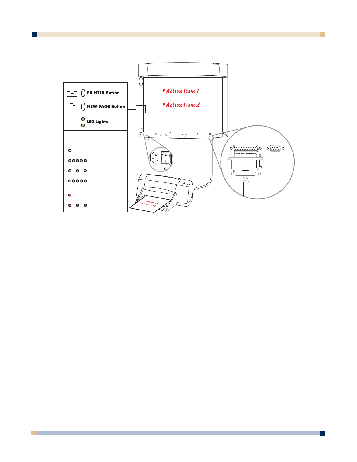
COPYBOARD MODE
1. Make sure the Master Power Switch is on and that the 3M™ Digital WallDisplay is
plugged in.
The
On/Off Button does not need to be turned on.
2. Use the digital markers to write on the board.
Use the digital eraser or cloth to erase any markings.
A printer will need to be plugged in to the printer port for direct print option.
3. Press the top bezel button to print.
4. Press the bottom bezel button to clear the page and any information stored in the buffer.
INSTALLING eBEAM SOFTWARE ON YOUR COMPUTER
Minimum Requirements
The eBeam Software will run on any computers that meet these minimum criteria:
PC
•Microsoft®Windows®compatible computer with Pentium® 100+ Mhz processor
•Windows 98, 2000, ME, XP and Windows NT 4.0 compatible (other platform users may
view shared meetings via Java™ applet through Java-enabled Internet browser)
• 10 MB available hard drive space
• 256-color VGA or SVGA monitor
• CD-ROM drive or Internet connection for software installation
• One available serial port or USB port
OPERATOR’S GUIDE
3 M™ DIGITAL WALLDISPLAY
Top LED Light Legend
NO DATA IN MEMORY
(No light)
BOARD IS RECEIVING DATA
MEMORY CONTAINS DATA
DATA IS PRINTING
CONNECTION ERROR
PRINTING ERROR
(Quickly blinking green)
(Slowly blinking green)
(Blinking with alternating
green and amber))
(Solid red)
(Slowly blinking red)
Printer Computer
Page 35

35
Apple Macintosh
Although this help system does not discuss specific Macintosh help topics, there are versions of
eBeam Software for Macintosh computers that meet the following requirements:
• Power Macintosh
• Mac OS 9.x with Macintosh Runtime for Java™ 2.2 or higher and 64 MB RAM, or
• Mac OS X 10.1 or higher
• 10 MB available hard drive space
• One available USB port
WHITEBOARD MODE
1. Plug in cables and insert markers into their digital sleeves.
2. On the attached computer, double-click the
eBeam Software icon on the desktop to
launch the program.
3. The top bezel button prints one copy of the active page to the default printer of the
attached computer.
Note: Choose New Page to save your work before you erase the board.
4. The bottom bezel button clears the current page and displays a new blank page on your
computer screen.
OPERATOR’S GUIDE
3 M™ DIGITAL WALLDISPLAY
Top LED Light Legend
COMMUNICATING WITH A PC
(Solid amber)
CONNECTION ERROR
(Solid red)
Printer Computer
Page 36

36
PROJECTION MODE
1. Turn on the 3M™ Digital WallDisplay unit and wait for image to appear on the screen.
2. Open a digital marker sleeve and slip the Digital Mouse stylus into the sleeve, instead of
a dry-erase marker.
3. From the
eBeam system tray menu, choose Use with Projector.
4. From the
eBeam system tray menu, choose Calibrate Projection Area.
5. Follow all on-screen directions from the calibration wizard.
Icons That Represent a Mode
There are various icons that indicate which mode eBeam Software is in. The following icons
appear within the eBeam Software’s Meeting application, as well as on your computer’s desktop.
OPERATOR’S GUIDE
3 M™ DIGITAL WALLDISPLAY
Icon Location
Status Icon
System Tray
Icon
Whiteboard Mode
Projection Mode Flipchart Mode Disconnected
Top LED Light Legend
COMMUNICATING WITH A PC
(Solid amber)
CONNECTION ERROR
(Solid red)
VGA
Printer Computer
Page 37

USING WHITEBOARD MODE AND PROJECTION MODE TOGETHER
Because eBeam Software’s Projection mode allows you to open any application on your computer, you can also open eBeam Software’s meeting application and use the Whiteboard mode and
Projection mode together.
When you attempt to open eBeam Software’s Meeting application, a dialog box appears asking
whether you want to use the eBeam hardware in Whiteboard mode or Projection mode. Choose
Projection mode.
Once eBeam Software’s Meeting application opens on your projected desktop, you can use the
Annotation Tools (with the digital marker and stylus) to draw or annotate within the whiteboard
mode application. You are also able to share or join a shared meeting (see Hosting/Sharing a
Meeting
and Joining a Meeting).
A useful presentation idea is to use the
Background Images feature in eBeam Software’s
Meeting application while in eBeam Software’s Projection mode. You can load a series of background images into eBeam Software’s Meeting application, which is then displayed on the whiteboard. In addition, you can share the eBeam Software meeting, which will then display your
background images to remote participants at the same time.
UNABLE TO DETECT THE HARDWARE
If eBeam Software is unable to detect the hardware, a Detect eBeam dialog box opens with the
message: “eBeam not detected.” This dialog box displays a list of available ports, and which
ports are available.
The
Detect eBeam dialog box includes the following controls:
Control Description
Port Status list
Lists of all ports on your computer, and whether they are
currently available.
Detect eBeam at Instructs eBeam Software whether to continue attempting to
application startup detect the hardware when eBeam Software starts up. See
Enable/Disable Connect at Startup.
Help Opens eBeam Software’s help system to this topic.
Setup Opens the eBeam Software Setup dialog. See Setup.
Cancel Cancels the detection process, but allows you to continue
working with eBeam Software.
Retry Attempts to detect the hardware again using either: your
settings in the eBeam Hardware Setup dialog (see Setup),
or your selection from the port list.
ENABLE/DISABLE CONNECT AT STARTUP
If you frequently use eBeam Software without the eBeam hardware, you can disable the Detect
eBeam hardware at startup feature.
To disable
Detect eBeam hardware at startup:
1. Open the
eBeam Hardware dialog by choosing Setup > eBeam Hardware from the
Edit menu.
By default, the
Detect eBeam hardware at application start check box is enabled.
37
OPERATOR’S GUIDE
3 M™ DIGITAL WALLDISPLAY
Page 38

38
2. To disable, uncheck the check box.
To later enable detection at startup, check the check box.
3. Click
OK.
MANUALLY DETECTING THE eBEAM HARDWARE
When the Detect eBeam hardware at application start preference is disabled, you must
manually instruct eBeam Software to detect the eBeam hardware.
To detect the hardware manually:
• In eBeam Software’s Meeting application, choose
eBeam Hardware > Detect from the
Tools menu.
• In eBeam Software’s Meeting application, left-click the
eBeam Status icon.
• Switch into an eBeam Software mode.
SELECTING MODE AT STARTUP
To make it easier for you to specify how you plan to use eBeam Software, the first time eBeam
Software launches and detects portable eBeam technology, a mode selection dialog box appears.
This dialog box allows you to select which mode to use eBeam Software in. Possible selections
are:
• Whiteboard mode
• Flipchart mode (Not available with 3M™ Digital WallDisplay)
• Projection mode
To select a mode at startup, first select the mode that you wish to use eBeam Software in.
Next, click the
How to Calibrate button to open the calibration wizard for to the mode you
have selected.
SELECTING A PORT SETTING
A “port” is the connection on your computer between eBeam Software and the hardware. The
default port settings are appropriate for most situations. Most often, setting the software to
autodetect the hardware is the best choice. However, if your hardware is not detected, use the
following procedure to review the serial port setting.
To check the serial port setting:
1. Open the eBeam Hardware
Setup dialog box by:
• Clicking the
eBeam Hardware Setup button from the Detect eBeam dialog (which
opens automatically when detection fails); or
• Choosing
eBeam Hardware > eBeam Hardware Setup from the Tools menu within
eBeam Software’s Meeting application; or
• Choosing
eBeam Hardware Setup from the eBeam’s system tray menu.
The
Autodetect radio button is enabled by default.
Note: For Microsoft®Windows®computers, note that Autodetect can detect COM1,
COM2, and USB only.
2. To specify a port, select the Connect to radio button, and then select a port setting from
the pull-down menu.
3. Click
OK.
At this point, the eBeam Software automatically attempts to detect the hardware at the
selected port.
If eBeam Software is unable to detect the hardware, see
Unable to Detect the Hardware.
OPERATOR’S GUIDE
3 M™ DIGITAL WALLDISPLAY
Page 39

39
eBEAM SOFTWARE’S MEETING APPLICATION
eBeam Software’s Meeting application is used in Whiteboard mode, and is used to record, save,
print, annotate, and share data from the whiteboard, as well as to share ongoing meetings over
your local intranet or even the Internet.
MENUS
eBeam Software’s Meeting Application Menu Bar
File Menu
New Creates a new meeting.
Open Opens a standard Open File dialog box. Navigate to the *.wbd
file, and select that file to open.
Close Closes the selected meeting.
Save Saves the selected meeting. If this is the first time the meeting
has been saved, the standard Save As dialog box opens,
allowing you to enter a meeting name and select the folder
location. If the file has been saved before, then it is saved again
under the existing name.
Save As Opens the standard Save As dialog box, allowing you to enter a
meeting name and select the folder location. For supported
formats for saving a file, see
Supported File Formats for Save
As/Send.
Import PDA Meetings Opens the Import PDA Meeting dialog box. See Import PDA
Meetings.
Print Opens the standard Print dialog box.
Print Page Prints the selected page only. See Application Toolbar.
Print Setup Opens the standard Print Setup dialog box.
Page Setup Opens the Page Setup dialog box. The Page Setup dialog box
allows you to choose header and footer information for the
printed page, as well as whether to place a border on the printed
page.
Available information includes: page numbering information,
the meeting name, the date and time in various formats, and the
eBeam logo.
Send Opens the Send dialog box, which allows you to send the
selected meeting (in various formats) to selected recipients
using your e-mail client. See
Send.
Exit
Closes the Meeting application.
OPERATOR’S GUIDE
3 M™ DIGITAL WALLDISPLAY
Page 40

40
Edit Menu
Undo Erases the previous whiteboard stroke or annotation. It is
possible to undo until the page is blank.
Redo Redoes the last undone whiteboard stroke/annotation. This
option is available when Undo was previously clicked. In the
case of multiple undos, it is possible to redo back to the final
whiteboard stroke/annotation in the page.
Redo is disabled
once the next new whiteboard stroke/annotation occurs.
Copy Copies the contents of the rectangle. The Selector tool
(located in Annotation Tools) allows you to draw a
selection rectangle, then copy and paste the contents of the
rectangle. Choose
Copy from the Edit menu to copy a
selected object to the clipboard. Data copied into the clipboard
can be pasted into other applications.
It is not possible to paste copied data into another Meeting
page. However, copied data is contained in the clipboard,
and can be included in an eBeam Meeting page as a
background image. See
Background Images.
Delete Text Deletes the entire selected text box. Available only when a
text box is selected. See the Text Tool description in
Annotation Tools.
Select All Selects the entire page. Used to copy the full page. See the
description of Edit > Copy above. Available only in the full
Page view. See Views and View-Change Buttons.
Setup Opens the Setup dialog box. The Setup dialog box contains
the following four tabs:
eBeam Hardware- See description of the eBeam Hardware
tab in
eBeam Hardware Setup.
Proxy Server - See Proxy Server Setup.
Preferences - See description of Preferences tab in
Preferences—Setup.
Image Size - See Image Size.
Web Tour - See Web Tour Setup.
eBeam Hardware Setup
The eBeam Hardware tab in the Setup dialog box allows you to set:
• Whether or not to automatically detect the hardware at software startup. See
Enable/Disable Connect at Startup.
• What the system will do once you shut down eBeam Software’s Meeting application.
See
Autolaunch eBeam Software.
OPERATOR’S GUIDE
3 M™ DIGITAL WALLDISPLAY
Page 41

41
Preferences—Setup
The Preferences tab in the Setup dialog box allows you to set:
• File autosave/backup settings. See
Autosave.
• Application toolbar preferences. See
eBeam Software Toolbar Preferences.
• Smooth lines (anti-aliasing). Smooth lines can be turned on/off by checking/unchecking
the
Smooth Lines (Antialiasing) check box.
View Menu
Tools/Toolbar Shows/Hides the Tools (Annotation Tools) and Play Controls
toolbars. Also allows you to choose At top or At bottom for
locating the toolbars at either the top or the bottom of the
Meeting application.
Zoom Magnifies/Zooms the current page. The following settings are
available for the currently displayed page in the
Page View:
Zoom In, Zoom Out, or 100%. See the Zoom tool in
Annotation Tools.
Full Screen Maximizes the current view to full screen size, hiding the menu
bar, and maximizing the application if necessary. Choose Full
Screen again to go back to normal mode. See Application
Toolbar
.
Thumbnails Switches to the Thumbnails View. See Views and the View-
Change Buttons.
Participants Switches to the Participants/Chat View. See Views and the
View-Change Buttons.
Pages Switches to the Page View. See Views and the View-Change
Buttons
.
Float Thumbnails View Separates the Thumbnails View and floats it as its own
window.
Float Participants View Separates the Participants/Chat View and floats it as its own
window.
Float Web View Separates the Web View and floats it as its own window.
Page Menu
New Page Creates a new page in the current meeting.
If the current meeting also contains the Active Page (page
currently receiving data from the eBeam system), the new page
becomes the Active Page. Otherwise, the new page does not
receive data from the eBeam system. For details on how to set a
meeting to receive data from the eBeam system when multiple
meetings are open, see the
Select eBeam Meeting description
in Tools menu.
Clear Page Clears the selected page.
Duplicate Page Duplicates the selected page, and inserts the new page follow
ing the duplicated page.
If the current meeting also contains the Active Page and the
page to be duplicated is the Active Page, the duplicated page
becomes the Active Page. Otherwise, if the duplicated page is
OPERATOR’S GUIDE
3 M™ DIGITAL WALLDISPLAY
Page 42

OPERATOR’S GUIDE
not the Active Page, the new page is not the Active Page. For
details on how to set a meeting to receive data from the eBeam
system when multiple metings are open, see the Select eBeam
Meeting description in Tools menu.
Delete Page Deletes the selected page.
Delete All Deletes all pages in the selected meeting.
Insert Page Before Inserts a new page before the selected page.
Current
Make Current Page Sets the selected page as the Active Page (page currently
Active receiving data from the eBeam system).
Next Page Switches to the next page in the meeting. This option is avail-
able only when the last page in the meeting is not currently
displayed.
Previous Page Switches to the previous page in the meeting. This option is
available only when the first page in the meeting is not current
ly displayed.
Go To Page Opens the Go To Page dialog box. To select a particular page,
type the page number and click OK.
Background Image Opens the Background Images dialog box. See Background
Images.
Meetings Menu
Share Meeting Opens the Share Meeting dialog box. See Hosting/Sharing a
Meeting and Sending an E-mail Invitation to a Meeting.
This option requires that eBeam Software be connected to
the eBeam hardware before the Share Meeting dialog box
will launch.
Join Meeting Opens the Join Meeting dialog box. See Joining a Meeting.
Send Invitation Opens your default e-mail client, allowing you to select
recipients from your own address book. See Sending an
E-mail Invitation to a Meeting.
This option requires that a shared meeting be in session.
See Shared Meetings.
Participants Information. Displays a dialog box showing a summary of
information about the selected participant. Some information
includes: name, role (coordinator or participant), interactive?
(allowed to annotate?), time connected, IP address, domain
name, and any notes entered into the notes field in the Share
Meeting or Join Meeting dialog boxes.
Set View Only. Mutes the selected meeting participant. The
participant is able to view everything that occurs in the meeting
but is not able to annotate the meeting. The participant can still
chat in the Particpants View. See Views and the View-
Change Buttons and Using eBeam Chat. Only available if
you are the meeting host. See Hosting/Sharing a Meeting.
42
3 M™ DIGITAL WALLDISPLAY
Page 43

3 M™ DIGITAL WALLDISPLAY
Exclude Participants. Disconnects the selected participant
from the shared meeting. This option is available only if you
are the meeting host. See Hosting/Sharing a Meeting.
Set View Only - All. Mutes all meeting participants. The partic
ipants are able to view everything that occurs in the meeting but
are not able to annotate the meeting. The participant can still
chat in the Participants View. See Views and the View-
Change Buttons and Using eBeam Chat. Only available if
you are the meeting host. See Hosting/Sharing a Meeting.
Synchronize Participants Forces all participants to view the same page as the host. Only
available if you are the meeting host. All meeting participants
are forced to view the page that the host is viewing. When the
host switches pages, all participants automatically switch at the
same time. See Hosting/Sharing a Meeting.
The Synchronize button is available on the View control bar.
See Views and the View-Change Buttons.
Tools Menu
eBeam Hardware Detect. Attempts to detect the eBeam Hardware.
Setup. Opens the eBeam Hardware Setup dialog box.
See Selecting a Port Setting.
Calibrate Capture Area. Opens the calibration wizard.
Capture from Whiteboard. Switches eBeam Software to
Whiteboard Mode.
Capture from Flipchart. (Not available with 3M™ Digital
WallDisplay)
Use with Projector. Switches eBeam Software to
Projection Mode.
Disable System. Disconnects eBeam Software from the
hardware. Frees the communication port.
Shortcut Strip (Not available with 3M Digital WallDisplay)
Sleeve Settings Opens the Sleeve Settings dialog box. See Setting Pen
Colors/Line Thickness.
Select eBeam Meeting Opens the Select eBeam Meeting dialog box that allows
you to select which open eBeam meeting is currently
receiving input from the 3M Digital WallDisplay. Select an
open meeting from the pull-down menu, and then select OK.
The meeting must be open for its name to appear in the
Select eBeam Meeting dialog box.
Microsoft NetMeeting Opens Microsoft
®
NetMeeting®to use for online meetings.
Requires that NetMeeting has previously been installed
on your Windows
®
computer.
Windows Menu
Cascade Cascades all open meeting windows.
Tile Horizontally or vertically tiles all open meeting windows.
Meeting List Displays the names of all open meetings. Selecting a meeting
name brings that meeting to the forefront.
OPERATOR’S GUIDE
43
Page 44
44
Help Menu
Contents Opens the online Help system.
Online Support Opens your web browser and loads the www.e-beam.com
support page.
Registration Opens your web browser and loads the www.e-beam.com
registration page.
Common Questions Opens your web browser and loads the www.e-beam.com
FAQ page.
Software Update Opens your web browser and loads the www.e-beam.com
downloads page.
Check for Updates Opens the Check Application Version dialog box.
System Information Opens the standard System Information dialog box.
About eBeam Software Displays the About dialog box for eBeam Software. To close,
click anywhere in the About dialog box.
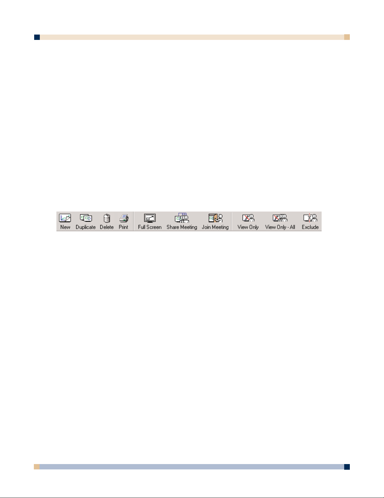
APPLICATION TOOLBAR
eBeam Software’s Meeting application toolbar is located at the top of the meeting application
window, under the menu bar.
New Creates a new page in the current meeting. Also available in the
Page menu.
If the current meeting also contains the Active Page (page
currently receiving data from the eBeam system), then the new
page becomes the Active Page. Otherwise, the new page does
not receive data from the eBeam system. For details on how to
set a meeting to receive data from the eBeam system when
multiple meetings are open, see the
Select eBeam Meeting
description in Tools menu.
Duplicate Duplicates the selected page, and inserts the new page
following the duplicated page. Also available in the
Page
menu.
If the current meeting also contains the Active Page and the
page to be duplicated is the Active Page, then the duplicated
page becomes the Active Page. If the duplicated page is not the
Active Page, the new page is not the Active Page. For details on
how to set a meeting to receive data from the eBeam system
when multiple meetings are open, see the
Select eBeam
Meeting description under Tools menu.
Delete Deletes the selected page. Also available in the Page menu.
Print Prints the selected page. Also available in the Page menu.
Full Screen Maximizes the current view to full screen size, hiding the
menu bar, and maximizing the Meeting application, if
necessary. To go to back to normal mode, click
Full Screen
again. Also available in the View menu.
OPERATOR’S GUIDE
3 M™ DIGITAL WALLDISPLAY
Page 45

45
Share Meeting Opens the Share Meeting dialog box. See Hosting/Sharing a
Meeting
and Sending an E-mail Invitation to a Meeting.
Also available in the
Meetings menu.
This option requires that the eBeam Software be connected
to the eBeam hardware before the Share Meeting dialog
box will launch.
Join Meeting Opens the Join Meeting dialog box. See Joining a
Meeting
. Also available in the Meetings menu.
View Only Mutes the selected meeting participant. The participant is
able to view everything that occurs in the meeting but is not
able to annotate the meeting. The participant can still chat
in the
Participants View.
This option is shown only when the
Participants/Chat
View
is displayed.
See
Views and the View-Change Buttons and Using eBeam
Chat
. Also available in the Meetings menu.
Only available if you are the meeting coordinator/host. See
Hosting/Sharing a Meeting.
View Only—All Mutes all meeting participants. The participants are able to
view everything that occurs in a meeting, but are not able to
annotate the meeting. The participants can still chat in the
Participants View.
This option is shown only when the
Participants/Chat
View
is displayed.
See
Views and the View-Change Buttons and Using eBeam
Chat
. Also available in the Meetings menu.
This option is only available if you are the meeting coordinator/
host. See
Hosting/Sharing a Meeting.
Exclude Disconnects selected participant from the shared meeting. This
option is shown only when the
Participants/Chat View is
displayed.
See
Views and the View-Change Buttons and Using eBeam
Chat
. Also available in the Meetings menu.
This option is only available if you are the meeting coordinator/
host. See
Hosting/Sharing a Meeting.
eBeam Software Toolbar Preferences
You can specify whether to show only icons, only text, or both icons and text on the toolbar.
To specifiy your toolbar preferences:
1. Choose
Setup from the Edit menu.
The
Setup dialog box opens.
2. Click the
Preferences tab. Under the Preferences tab, there are check boxes for both
icons and text. Acheck mark causes the icons or text to be shown.
3. Select icons and/or text.
4. Click
OK.
OPERATOR’S GUIDE
3 M™ DIGITAL WALLDISPLAY
Page 46
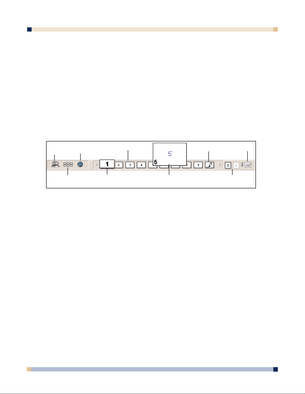
46
Views and View-Change Buttons
The view area is the center of eBeam Software’s Meeting application window. eBeam
Software’s Meeting application has several views:
•
Page Display View: The Page Display View displays a single meeting page at one time,
allowing you to see each new whiteboard drawing as it is drawn.
•
Participants View: The Participants View shows you who is logged into a shared
meeting, and allows the logged in participants to chat online. See Using eBeam Chat.
• Thumbnails View: The Thumbnails View displays thumbnails of all pages in the meet-
ing. Use the scroll bar on the right to scroll through all available thumbnails. Selecting a
thumbnail opens that page in the
Page Display View.
•
Web View: The Web View allows access to web pages, and allows the meeting host to
lead a Web Tour.
The
View-Change toolbar (shown below) is used to navigate between the different views.
Each control in the
View-Change toolbar is described below:
Switch to Participants Switches to the Participants View. See Using eBeam
View Button Chat.
Switch to Thumbnails Switches to the Thumbnails View.
View Button
Switch to Web View Button
Switches to the Web View. See Web Tour.
Page Select Scrollbar Displays a page button for all pages contained in the
meeting. The button for the currently displayed page
in the
Page View is larger and overlaps the other
page buttons (see example for page 1 in the image).
If the number of pages exceeds the amount of space
in the scroll bar, the scrolling arrows become active.
See Reordering Meeting Pages.
Rolling your mouse pointer over a page button
causes a thumbnail of that page to pop up (see
example 5 in the image). This allows you to see the
page without displaying the page in the Page View.
Moving the mouse pointer away from the page
button closes the pop-up.
Currently Displayed Page Shows the currently displayed page in the Page
Display View. When a page is displayed in the Page
Display View, the corresponding button in the Page
Select Scrollbar
is larger than the other buttons. See
Reordering Meeting Pages.
OPERATOR’S GUIDE
3 M™ DIGITAL WALLDISPLAY
Switch to
Participants
View Button
Switch to
Thumbnails
View Button
Currently
Displayed
Page
Mouse Rollover-
Quick Page
Preview
Previous Page/
Next Page
Switch to
Web View
Button
Page Select
Scrollbar
Active
Page
Synchronize
Button
Page 47

47
Mouse Rollover- Opens thumbnail. Rolling your mouse over a page
Quick Page Preview on the Page Select Scrollbar and then holding it for
a second causes a thumbnail of the page to pop up.
Moving the mouse away from the
Page Select
Scrollbar closes the thumbnail.
Active Page Shows the Active Page icon that is currently receiving
whiteboard data from the hardware. See
Page Menu
and Reordering Meeting Pages.
Previous Page/Next Page Displays the previous or next page in a meeting.
Buttons Previous Page button is enabled only if the currently
displayed page is not the first page in the meeting.
The
Next Page button is enabled only if the currently
displayed page is not the last page in the meeting.
Synchronize Button Causes all participants to be forced to view the same
page as the meeting host. For details, see the
Synchronize feature in What Can the Meeting
Coordinator/Host Do?
REORDERING MEETING PAGES
You can reorder or move meeting pages on the Page Select scrollbar by using your mouse to
drag a page to its new location.
As you drag the page, an indicator arrow appears on the scrollbar that lets you know where the
page will be inserted. Once the page has been moved, all pages are immediately renumbered. If
you have moved a page to a higher page number location, all other pages will shift down. If you
move a page to a lower number location, all other pages will shift up.
Note: You cannot undo a page move.
SETTING PEN COLORS/LINE THICKNESS
The Sleeve Settings dialog box defines how strokes made on the whiteboard with a digital
marker are represented in eBeam Software’s Meeting application window.
eBeam Software’s Meeting application has default screen colors and line thickness already
defined; however, you can modify these default colors and line thicknesses to suit your needs.
To set pen colors and line thickness:
1. Choose
Sleeve Settings from the Tools menu.
2. Select the desired line thickness for each digital marker. Each digital marker has a
corresponding picture and set of line thicknesses in the
Sleeve Settings dialog box.
Note: On-screen line weights may appear thicker or thinner than the actual marker
strokes on the whiteboard.
3. Select the desired screen colors for each digital marker.
The
Color dialog box appears.
Your screen colors can differ from the dry-erase marker and the ring on the electronic
pen, if desired. You can create your own colors or use the basic colors provided.
In the
Sleeve Settings dialog box, the screen color bar changes to reflect the color you
selected for each sleeve color.
OPERATOR’S GUIDE
3 M™ DIGITAL WALLDISPLAY
Page 48

48
To return the sleeve colors to the default setting, click the Restore Defaults button.
4. Click
OK to save your color choices.
Changing Width/Color of Previously Recorded Strokes
To change width/color of previously recorded strokes:
1. Choose
Sleeve Settings from the Tools menu.
2. Select the desired new line width/new color.
3. For both the line width, and line color, select
Apply to Previous Strokes, and specify if
you would like this to apply to the current page only or all pages in the meeting.
4. Click
OK to apply the width change.
Changes to the color or line width of pen strokes cannot be undone.
ANNOTATION TOOLS
The Annotation Toolbar is a palette of tools that allow the user to annotate/draw on the
displayed meeting page using the computer’s mouse and keypad.
Some uses for the
Annotation tools include:
• Highlighting an important item on the whiteboard.
• Adding text notes to a page that elaborate on the meaning of the whiteboard drawing.
• Highlighting items that remote participants should pay close attention to during a shared
meeting. See
Using Annotation Tools During a Shared Meeting.
• Creating meeting pages, when using eBeam Software’s Meeting application in Projection
mode. See
Using Whiteboard Mode and Projection Mode Together.
Marker The Marker tool allows you to annotate the displayed page
freehand in one of four solid colors. The color can be selected
from the palette that appears when the
Marker tool is selected.
Highlighter The Highlighter tool allows you to annotate the displayed page
freehand in one of four transparent colors. The color can be
selected from the palette that appears when the
Highlighter
tool is selected.
Eraser The Eraser tool allows you to erase (from the displayed page)
both the marker strokes drawn on the whiteboard and the annotation marks made with the Annotation tools. The eraser size
can be selected from the palette that appears when the
Eraser
tool is selected.
Zoom The Zoom tool allows you to adjust the viewing size of the dis-
played page. The range of zoom values are 100-2000%.
Holding down the
Shift key reverses the zoom direction. A
zoom value can also be selected from the pull-down menu that
appears when the Zoom tool is selected.
OPERATOR’S GUIDE
3 M™ DIGITAL WALLDISPLAY
Marker
Eraser
Text
Selector
Highlighter
Zoom
Pointer
Page 49

49
Text The Text tool allows you to add text annotations to a meeting
in any size, font, and color available on your computer. The
size, font, and color may be selected from the palette that
appears when the
Text tool is selected.
Pointer The Pointer tool allows each participant in a meeting to
point to data anywhere within the meeting window. Each
participant’s pointer is displayed in a different color.
The
Pointer tool is only enabled during a shared meeting.
The pointer direction (right, left, up, down) can be selected
from the palette that appears when the
Pointer tool is
selected. You can also hide the pointer by clicking the Hide
Pointer button from the palette that appears when the
Pointer tool is selected.
Selector The Selector tool allows you to draw a selection rectangle
and copy the selection. The selected rectangle can then be
pasted into another application.
Using Annotation Tools During a Shared Meeting
During an online meeting (see Shared Meetings), connected participants can create annotations
to the meeting which are visible to all other participants in the meeting.
If the meeting is not synchronized by the meeting host, and the participant has not been set to
View-Only, the participant may annotate on any page in the meeting. See What Can the
Meeting Coordinator/Host Do?
and What Can a Meeting Participant Do?
If the meeting is synchronized by the meeting host, the participant is restricted to annotating
only on the displayed page.
If the participant has been set to
View-Only by the meeting host, the participant cannot annotate
the meeting. The Zoom tool is always available, but zooming in/out of a page is not visible to
other participants.
PLAY CONTROLS
The Play Controls toolbar allows you to replay the meeting like a movie. The meeting can then
be played forward, line by line, at varying speeds. Playback can be restricted to either the current page, or set to play all pages.
Some uses for the
Play Controls:
•Viewing the meeting chain of events.
• Branching, which returns the meeting to a specific point and then duplicates the page.
The duplicated page will create a new page with meeting data to the selected endpoint,
allowing you to explore a different idea without manually duplicating previous work, and
keeping the original page intact.
Jump to Beginning Jumps to the very beginning of the meeting, which is always
the original blank page.
OPERATOR’S GUIDE
3 M™ DIGITAL WALLDISPLAY
Jump to Beginning
Drag Control Slider
Jump to End
Loop
Play
All Pages
Play Speed
Page 50

50
Drag Control Slider Allows you to step through the meeting forward or reverse by
clicking on the drag line, or to immediately jump to a specific
point in the meeting by dragging the drag bar to a location on
the drag line.
Play Replays the meeting from beginning to end, beginning with a
blank screen. While playing, the
Play button changes to a Stop
button, allowing you to stop the playback. See Play Speed.
Jump to End Jumps to the end of the meeting, restoring all whiteboard
strokes and annotations.
All Pages Sets the number of pages affected by Play Controls. If All
Pages is checked, clicking Play causes the entire meeting to be
played back. If
All Pages is not checked, only the currently
displayed page is played back.
Loop Replays the meeting from beginning to end, beginning with a
blank screen. Once the end of the meeting is reached, it begins
to replay from the beginning and runs continuously. While play
ing, the
Play button changes to a Stop button, allowing you to
stop the playback.
Play Speed Sets the speed at which the meeting is played. The slowest
speed is 0.5x; the fastest speed is 8.0x.
BACKGROUND IMAGES
You can import a file, screen capture, or data from the clipboard as a background image on the
page currently displayed in Page View. The background image remains in the background of
the currently displayed page. Any markings, including typed text, digital marker strokes, or erasures, remain visible in front of the image.
During a shared meeting, background images are displayed to all participants:
To load/remove a background image:
1. Navigate to the meeting page you wish to load the background image into.
2. Choose
Background Image from the Page menu, or drag-and-drop the file onto the
page.
This opens the
Background Image dialog box which contains the following options:
Load Image Opens the standard Open dialog box. To load an image, navi-
gate to and select the file you want to load into the page background, and then click
OK.
The file to be imported is displayed in the preview window of
the
Background Image dialog box. To add, click OK.
See
Supported File Formats for Background Images,
Loading an Excel Spreadsheet as a Background Image, and
Loading a Powerpoint Presentation as a Background Image.
Load from Clipboard Loads data from the computer’s clipboard as the background
image. If there is no data in the computer’s clipboard, this
button is disabled.
OPERATOR’S GUIDE
3 M™ DIGITAL WALLDISPLAY
Page 51

51
The data from the system’s clipboard is displayed in the
preview window of the
Background Image dialog box. Click
OK to add.
In general, capturing a screen or copying data within an
application will load data into the system’s clipboard.
Capture Screen Creates a capture rectangle by holding down the left mouse
button and dragging the pointer across the screen until the
rectangular outline encloses the area of the screen you wish to
capture.
Clicking Capture Screen causes eBeam Software’s Meeting
application to minimize.
Release the mouse button, and the captured area is displayed in
the preview window of the
Background Image dialog box.
Click OK to add the captured area as a background image.
Remove Image Removes the background image from the page. Any whiteboard
strokes or annotations will remain on the page.
Keep Aspect Ratio Sets the proportions of the background image. If the Keep
Aspect Ratio check box is checked, the image is loaded into
the background in proportion to the original. If the
Keep
Aspect Ratio check box is not checked, the image is stretched
to fill the page when loaded into the background.
Load Image, Load from Clipboard, and Capture Screen load into the displayed page, rather
that beginning a new page. When using these features, make sure that you are not overwriting a
previously loaded background image.
Supported File Formats for Background Images
Listed below are supported file types.
• Bitmap (*.bmp)
• Graphic files (*.gif, *.jpg, *.ico, *.emf, *.wmf)
•Microsoft
®
Excel®spreadsheets (*.xls)
• Powerpoint
®
presentations (*.ppt)
•Word
®
documents (*.doc, *.rtf)
If you attempt to load a file that is not supported, the page will display a large icon associated
with file type, and the filename, but will not attempt to load that file onto the page.
Loading an Excel Spreadsheet as a Background Image
To load an Excel spreadsheet as a background image:
1. Choose
Background Image from the Page menu, and use the Load Image button to
load the Excel (*.xls) file.
For details on how to use the
Load Image button, see Background Images.
You can also drag-and-drop an Excel (*.xls) file onto the page to open it as a background
image.
OPERATOR’S GUIDE
3 M™ DIGITAL WALLDISPLAY
Page 52

52
Note: It is not possible to load an Excel spreadsheet that contains a graph.
2. If there is more than one worksheet in the *.xls file, the Excel Spreadsheet Import
dialog box opens. Specify to either:
• Load the data from one sheet only, or
• Load data from many sheets and use them for new pages.
3. To load data from one sheet only, specify the sheet and the range of cells to be used. You
can preview the image by clicking the
Show Preview button.
4. To load data from many sheets, specify the sheets to be used. You can also choose to have
the first loaded image placed on the last existing meeting page.
There is a limit to the number of rows and columns you can import from a sheet. The data range
you can select depends on whether you are loading data from one sheet or from many sheets.
Loading a Microsoft®PowerPoint®Presentation as a Background Image
To load a Powerpoint presentation as a background image:
1. Choose
Background Image from the Page menu, and use the Load Image button to
load the PowerPoint (*.ppt) file. For details on how to use the
Load Image button, see
Background Images.
You can also drag-and-drop a PowerPoint (*.ppt) file onto the page to open it as a back
ground image.
The
Multiple Page Background dialog box appears, with a description of the
Powerpoint presentation size and a list of options.
2. Decide how much of the presentation you want to include as a background image to the
meeting by choosing one of the following:
• Load one image only and use it for the current page—loads one image that you specify
by scrolling to the appropriate slide number.
• Load many images and use them for new pages—loads slides that fall within the range
you specify.
• Use the first loaded image for the last existing page—loads the first page of the *.ppt
presentation starting at the last existing meeting page.
3. Click
OK.
FILE EXPORT/IMPORT/AUTOSAVE
Export to File Format
To save an eBeam file as a different file format:
1. Choose
Save As from the File menu.
The
Save As dialog box appears.
2. Select the file format from the
Save As Type pull-down menu.
If there are any special page options available for the selected format, they are
displayed directly beneath the
Save As Type pull-down menu immediately after the
format has been selected.
3. Click
Save.
OPERATOR’S GUIDE
3 M™ DIGITAL WALLDISPLAY
Page 53

53
For supported file formats, see Supported File Formats for Save As/Send.
Import PDA Meetings
Import PDA Meetings is used to import an eBeam database into your computer from a Palm™
handheld. eBeam software for the Palm handheld can be found at
www.e-beam.com.
To import a PDA database:
1. Choose
Import PDA Meetings from the File menu.
2. Select the user name.
Because some PDA software allows for several users to be set up on one computer,
you must select which user directory to search.
3. If you had previously chosen to install the PDA directory in a non-standard directory,
you must change the directory location by clicking the
Browse button. Select the
appropriate directory.
Once the directory is located, all eBeam meeting files contained in the PDA database
appear.
4. Select the files you want to import from the list.
5. Click
OK.
Send
You can send an eBeam Software Meeting file as an e-mail attachment via any MAPI-compliant
e-mail system, such as Microsoft®Exchange®. This option is available when Microsoft
Exchange is installed as your mail system.
1. Choose
Send from the File menu.
The
Send dialog box opens.
2. Select the file format and page range in the
Send dialog box.
Supported file formats are listed in
Supported File Formats for Save As/Send.
3. Click
OK.
eBeam opens an untitled e-mail message in your MAPI-compliant mail program with
your file as an attachment. Use your address book to fill in names of the recipients,
and send the e-mail as you normally would.
You can save an eBeam meeting in any file format (except HTML) that is suitable for an e-mail
attachment. HTML is not available because a folder (containing meeting pages) is created, and
eBeam Software cannot attach a folder to an Exchange message.
Image Size
The Image Size tab (Edit Menu > Setup dialog box) allows you to modify meeting files
created using the File Menu > Save As and File > Send menu options. See File Menu and
Send.
When the size of the calibrated whiteboard changes, the size of the meeting page image also
changes. If the whiteboard has been recalibrated and the viewable area expanded, the image
expands to work within the new height and width ratio, as long as the
Keep Aspect Ratio
checkbox is checked.
For a table of supported export formats, see
Supported File Formats for Save As/Send.
OPERATOR’S GUIDE
3 M™ DIGITAL WALLDISPLAY
Page 54

54
To modify the image quality:
1. Choose Setup from the Edit menu.
2. Click the
Image Size tab.
3. Enter the width and/or height of the image, either by scrolling to the desired value or
entering a number.
4. Select whether to keep the width and height ratio by checking or clearing the
Keep
Aspect Ratio check box.
The
Keep Aspect Ratio check box is checked by default. Note that when Keep Aspect
Ratio is checked, a change made to either the height or the width automatically changes
the other dimension. This ratio reflects the ratio calibrated for the whiteboard.
5. To save modifications, click
OK.
6. To restore the default settings, click the
Restore Default button.
If the whiteboard image appears stretched in either direction, make sure the
Keep Aspect Ratio
check box had been checked.
Autosave
The Autosave feature ensures that you don’t lose your meeting data if the power goes out, your
laptop runs out of battery life, etc.
The default
Autosave setting is set to back up your file every 5 minutes.
To adjust the
Autosave setting:
1. Choose
Setup from the Edit menu.
The
Setup dialog box opens.
2. Enable/or disable autosave by checking/unchecking the
Save Recovery File every:
check box.
3. Choose how often your meeting data will be saved by changing the number of minutes.
Supported File Formats for Save As/Send
The following is a list of file formats supported for saving a meeting or using the Send to
distribute a meeting.
• eBeam software file (*.wbd) • EPS monochrome (*.EPS)
• PDF (*.PDF) • JPEG (*.JPG)
•Vector PDF (*.PDF) • TIFF (*.TIF)
• HTML (*.HTM) (not available for
Send)•Metafile (*.emf)
• 24-bit bitmap (*.BMP) • 256 color bitmap (*.BMP)
•Microsoft
®
PowerPoint®presentation (*.PPT) • Monochrome bitmap (*.BMP)
• PowerPoint show (*.PPS)
AUTOLAUNCH eBEAM SOFTWARE
The eBeam Hardware tab (located in the Edit > Setup dialog box), allows you to decide what
the eBeam system will do when you close the eBeam Software’s Meeting application.
OPERATOR’S GUIDE
3 M™ DIGITAL WALLDISPLAY
Page 55

55
Although you may have closed eBeam Software’s Meeting application, as long as the eBeam
system remains connected to your computer, the hardware will continue to pick up signals from
the digital markers and eraser.
When eBeam Software’s Meeting application is closed and either the digital marker or eraser is
detected by the eBeam system, you can set the eBeam system to do one of following:
• Launch in Whiteboard mode
• Launch in Projection mode
• Disconnect from the eBeam hardware when eBeam Software’s Meeting application
closes, thus freeing the COM port.
To select one of the previously described settings:
1. Choose
Setup from the Edit menu.
2. Click the
eBeam Hardware tab in the Setup dialog box.
3. In the
After this application is closed: pull-down menu, select one of the following
options:
Start this application if Sets the eBeam system to monitor for digital marker/
eBeam hardware signal is eraser use. If a digital marker or eraser signal is
detected detected, eBeam Software’s Meeting application is
launched (Whiteboard mode) and immediately
begins to record whiteboard data.
Use eBeam with Projector Sets the eBeam system to monitor mode for digital
marker/eraser use. If a digital marker signal is
detected, eBeam Software’s Projection mode is
activated.
Disconnect eBeam from Disconnects eBeam Software from the communication
all applications port. This allows other devices or applications to use
the port.
4. Click
OK.
SHARED MEETINGS
What Is an eBeam Meeting?
An eBeam meeting is a collection of notes and annotations which may consist of a single page
or multiple pages. In either case, all pages contained in one eBeam Software’s Meeting application (*.wbd) file.
A single meeting may have one or more participants who are sitting in one room using eBeam to
capture notes and diagrams. Asingle meeting may also have participants who are located in
other locations, such as another floor in your building, another state, or even another country.
What Is a Shared Meeting?
A shared eBeam meeting is a meeting that is broadcast over your local intranet or over the
World Wide Web (Internet).
At one location, the meeting coordinator/host uses the eBeam system (software and hardware) to
broadcast the meeting over the network (see
Hosting/Sharing a Meeting). Remote participants
use eBeam Software’s Meeting application or a web browser to log into the meeting (see
Joining a Meeting).
OPERATOR’S GUIDE
3 M™ DIGITAL WALLDISPLAY
Page 56

56
The meeting is broadcast in real time, which means that remote participants see the lines as they
are drawn.
If the meeting coordinator/host allows participants this option, participants can annotate meeting
pages, highlighting important points, and adding notes that can be seen by all other participants
as well as the host.
To allow remote participants (located outside of your local network firewall) to access your
shared meeting, the meeting server must be located on the Internet. EFI currently hosts a meeting server that may be used by any eBeam system user.
Hosting/Sharing a Meeting
The following explains how to host/share a meeting over your local intranet or the Internet. If
you share the meeting on your local intranet, only people within your intranet can access the
meeting. If you share your meeting over the Internet (using the EFI server), participants from
any Internet location can access your meeting.
To share a meeting, you must be connected to the eBeam hardware.
To host a shared meeting:
1. Choose
Share Meeting from the Meetings menu or the Share Meeting button from the
Application Toolbar.
The Share Meeting dialog box opens.
2. Under Meeting Information, enter:
• Meeting Name. The meeting name is the name shown in the Join Meeting dialog box.
The meeting name is saved as the default name for subsequent meetings, until you
change it. The meeting name can be up to 20 characters.
•
My Name. The name displayed in the Participants/Chat View. See Using eBeam
Chat
.
• Notes. Any notes or comments you would like to include.
• Publish Meeting Name. Select Publish Meeting Name if you want the name of
the meeting to be visible to network users who are attempting to join a meeting
using either the
Join Meeting (see Joining a Meeting) dialog box, or the Meetings
web page located at www.e-beam.com.
If you do not publish the name, guests will need to know the full meeting name
beforehand and manually type it into the
Join Meeting dialog box.
• Password/Confirm/Use Password. If a password is required, check the Use
Password
check box and type the same password into both the Password and
Confirm text boxes.
The password must be at least 6 characters, and can be up to 20 characters.
•
Send Meeting Invitation. Meeting invitations are e-mail invitations that are sent out
using your standard mail client. If
Send Meeting Invitation is checked, the Send
Invitation
dialog box opens once you click the Share button. See Sending an E-mail
Invitation to a Meeting
.
3. Under Server Information, select the server that will host the meeting.
The pull-down menu lists the eBeam Server and any other servers you have
previously added to your server list. See
Adding a Meeting Server.
Note: For PC, if you wish to host the meeting from your computer, select Use
my PC to host this meeting
, and then type in a port number. For most
occasions, the default port value of 80 is best.
OPERATOR’S GUIDE
3 M™ DIGITAL WALLDISPLAY
Page 57

57
4. Notify guests of the meeting name, meeting time, and password, if required. See Sending
an E-mail Invitation to a Meeting
.
5. Click
Share.
Your shared meeting is now available on the network using the specified meeting server.
If a participant is attempting to join a meeting, but is unable to see the meeting name in the
Join
Meeting dialog box, both the meeting host and participant should check their proxy server
settings. See
Proxy Server Setup. Also, check to make sure that you checked Publish Meeting
Name in the Share Meeting dialog box.
Adding a Meeting Server
When you share or join a meeting, you must choose a meeting server. You can enter the server
information each time, or you can create a list of frequently used servers and select from this list
whenever you share or join a meeting.
To add a meeting server to your list:
1. Choose
Share Meeting or Join Meeting from the Meetings menu or from the
Application Toolbar.
2. In the
Share Meeting or Join Meeting dialog box under Server/Server
Information
, click the server button alongside the server pull-down menu.
The
Meeting Servers dialog box opens.
3. Click the
Add button.
4. Type the server name, the DNS name or IPaddress of the server you want to add to
your list, and the port number. The default port number is 80.
5. Click
OK.
The new server is added to the
Meeting Servers list.
Proxy Server Setup
If your company requires a proxy server, your computer will not be able to access meetings on
the eBeam Server (which is outside your company’s firewall) until you enable the proxy server
and enter the proxy server settings.
The
Setup dialog box gives you a place to enter settings for an HTTP proxy server. Proxy
servers, which act as intermediaries between individual workstations and the Internet, provide
security and other administrative functions for companies that use the Internet.
To set up a proxy server:
1. Choose
Setup from the Edit menu.
The
Setup dialog box opens.
2. Click the
Proxy Server tab.
3. If your network requires a proxy server, select
Access the meeting server using an
HTTP proxy server, and then do one of the following:
•
Basic Authentication. Use the basic authentication feature, which allows you to check
Use Authentication (Basic Only) checkbox. You then type in your network user ID
and password. In many cases this will allow you to access Internet meetings through
your proxy server.
•
Manual Entry. If the basic authentication feature does not work, you can enter the IP
address or DNS name and the port of the proxy server.
OPERATOR’S GUIDE
3 M™ DIGITAL WALLDISPLAY
Page 58

58
Sometimes it is possible to locate proxy server settings on your computer without going
through your IS department, by accessing information stored in your web browser.
To obtain these settings yourself:
Windows
®
• In Internet Explorer®, go to Tools > Internet Options. This launches
the Internet Options dialog box. Click the Connections tab, and then
click the LAN settings button. Get the proxy server address and port
number from the
Proxy Server settings section.
• In Netscape
®
, go to Edit > Preferences. Click Advanced and then
click
Proxies. If Manual Proxy configuration is checked, click the
View button. Use the address and port number listed under HTTP.
Macintosh • Go to the Internet Control Panel, click the Advanced tab, and then
the
Firewalls icon. All proxy server information is displayed.
If you are unable to find the proxy information as described above, consult your network administrator.
4. Click
OK.
Hosting Multiple Meetings
eBeam Software’s Meeting application allows you to host (or join) multiple meetings at the
same time. You can display multiple meeting windows, or you can choose to view one meeting
at a time.
You can host multiple meetings in one of the following ways:
• Hosting a meeting on your computer, and hosting a separate meeting from the eBeam
server.
• Hosting multiple meetings from the eBeam server.
Only one meeting at a time can be shared/hosted from your computer.
You must indicate which meeting you want to use the eBeam hardware with because the eBeam
hardware must communicate with the meeting that is shared.
To select the meeting you wish to use your eBeam hardware:
1. Choose
Select eBeam meeting from the Tools menu.
2. Select the meeting name from the pull-down menu.
3. Click
OK.
Sending an E-mail Invitation to a Meeting
You can invite others to a shared meeting by sending an e-mail that contains a link or URL. To
send e-mail invitations, you must currently be sharing a meeting. Remote participants cannot
send out invitations.
To send an e-mail invitation:
1. Make sure you are sharing a meeting. See
Hosting/Sharing a Meeting.
2. Choose
Send Invitation from the Meetings menu.
This opens the
Select Language dialog box.
3. Select the language to be used for the e-mail invitation, and then click
Continue.
OPERATOR’S GUIDE
3 M™ DIGITAL WALLDISPLAY
Page 59

59
Note: Your e-mail program may or may not ask you to select the e-mail profile to
be used.
An eBeam Meeting Request appears in your e-mail application Send Mail window.
4. Enter the e-mail addresses of the recipients in the
To: field.
The e-mail invitation is sent with a link to download the latest eBeam Software and links to
enable the user to join the meeting via their web browser or eBeam Software.
JOINING A MEETING
There are two ways you can join meetings:
• Using the eBeam Software (see
To join a meeting as an eBeam user).
• Using a web browser (see
To join a meeting as a web user).
To join a meeting as an eBeam user:
1. Choose Join Meeting from the Meetings menu.
2. In the
Join Meeting dialog box, select the meeting server, enter your name, and select a
meeting name from the
Meeting list.
The
Meeting list shows active meetings whose names have been published.
If the pull-down menu does not include the meeting server you want, you can manually
type the server name. You can also add a server to your server list, so that you can quickly select it on another occasion. See
Adding a Meeting Server.
3. Click Refresh to update the list of published meetings.
4. If the meeting appears with a
Lock icon, enter the password.
If the meeting is not listed, enter the meeting name, and a password if required.
5. Click
Join.
There are restrictions on what a meeting participant can do within a shared meeting. For details
on what you can do while connected to a meeting, see
What Can a Meeting Participant Do?
When the host ends the meeting, participants receive the message “The meeting has ended.” The
meeting remains visible on your desktop. Once disconnected, participants still can print, save,
annotate, and modify the meeting.
If, at any point, you want to leave a meeting, choose
Leave Meeting from the Meetings menu,
or click the Leave Meeting icon from the Application Toolbar.
To join a meeting as a web user:
1. Launch your web browser.
2. In the
URL text box (Address or Location), type the IP address or DNS name of the
computer hosting the eBeam session.
If the meeting is hosted by the eBeam server, type
www.e-beam.com and click the
Meetings button.
3. Type your name in the
My Name text box, and the meeting name in the Meeting Name
text box. In the Meeting Password text box, type the password, if required.
4. Click
Join a Meeting.
If the meeting is in session, the eBeam window appears in your web browser. Participants
will see the full contents of the meeting.
OPERATOR’S GUIDE
3 M™ DIGITAL WALLDISPLAY
Page 60

OPERATOR’S GUIDE
Remote participants cannot print or save the meeting to disk. However, the host can save
the meeting and make it available to web users for viewing in a web browser or another
application.
At any point, you can choose Leave Meeting from the Meeting menu.
Accepting an E-mail Invitation
You can accept an e-mail invitation in one of the following ways:
• Click the http: link to join through your web browser.
• Click the file: link to join through your copy of eBeam Software.
• Download and install, and then manually launch eBeam Software’s Meeting application, if necessary. You can then click Join Meeting (see Joining a Meeting) and use
the meeting information listed in the e-mail to join the meeting.
• Manually open your browser, and copy and paste the link into the browser.
What Can the Meeting Coordinator/Host Do?
The meeting coordinator/host is the person responsible for setting up and broadcasting the
shared meeting.
In the course of the shared meeting, the meeting coordinator/host can do anything eBeam
Software’s Meeting application can do: draw whiteboard strokes, create annotations, create new
pages, delete pages, etc.
When the coordinator/host closes a shared meeting, all participants are disconnected. As the
meeting coordinator/host, make sure the meeting is completely over before attempting to close
the meeting.
The following special features allow the meeting coordinator/host to control the shared meeting:
Synchronize Forces all participants to view the same page as the meeting
coordinator/host. If Synchronize is disabled, remote participants can view any page they wish during the meeting. If
Synchronize is enabled, remote participants are unable to
change the pages. However, if Synchronize is enabled, remote
participants can annotate pages.
The Synchronize feature is located in the Meetings menu. A
check mark indicates that Synchronize is enabled.
A Synchronize button is also available on the Page View tool
bar (see Views and the View-Change Buttons). When
Synchronize is enabled, the button is depressed.
Set View Only Allows the coordinator to mute one or more of the remote
participants.
When a particular remote participant is muted, the participant
cannot add annotations to the meeting page (see Annotation
Tools). However, the participant can still type comments into
the Participants/Chat View (See Views and the View-Change
Buttons).
The meeting coordinator/host cannot be muted.
Set View Only can be accessed from the Meetings menu or the
Application Toolbar. You must be in the Participants/Chat
View, and have selected one or more participant name(s).
60
3 M™ DIGITAL WALLDISPLAY
Page 61

61
The Meetings menu and Application Toolbar also contain a
Set View Only-All option, which allows you to mute all
participants at once.
Exclude Allows the coordinator/host to disconnect a meeting participant
from the shared meeting.
Exclude can also be accessed from the Meetings menu or the
Application Toolbar. To use this feature, you must be in the
Participants/Chat View and have selected one or more partici
pant name(s).
What Can a Meeting Participant Do?
As a remote participant, you have connected to an active meeting (see Joining a Meeting) and
the full shared meeting from the host computer is displayed on your computer.
A remote participant does not have the same set of features as the meeting coordinator/host.
Features that are different for a participant are described as follows.
Synchronize If the meeting coordinator has not enabled Synchronize, remote
participants can view and scroll the pages in the meeting independent of other users.
If the meeting coordinator/host has enabled
Synchronize,
remote particpants are only able to view the page that the coor
dinator/host is viewing. However, remote particpants are still
able to annotate the page.
Set View Only If the meeting coordinator/host has set a remote participant to
View Only, the participant cannot annotate the page.
Page Functions For remote participants, New Page, Duplicate Page, Clear
Page
, and Delete Page are disabled.
Annotation Remote participants cannot erase or undo annotations made by
other participants.
USING eBEAM CHAT
The Participants View is used to display all participants who are logged into a shared eBeam
meeting, as well as to allow the participants to chat online during the meeting. To access the
Participants View, either click the Switch To Participants View button (see Views and the
the View-Change Buttons
) or choose Participants from the View menu.
The
Participants View contains two sections: the Chat Window and the Participants List.
Chat Window
The Chat Window allows participants in a shared meeting to send text messages to one another
in the course of the meeting. Messages can be sent to anyone listed in the
Participants List, by
typing a text message into the
New Message text box, and then clicking one of the buttons listed
next to
Send To.
The following controls are contained in the
Chat Window:
New Message Creates a new e-mail message. Type the new outgoing
text message into the
New Message text box, and then
select
All or Selected Participants to send the mes
sage.
OPERATOR’S GUIDE
3 M™ DIGITAL WALLDISPLAY
Page 62

62
Show Addressee Lists the name(s) of e-mail recipients. If Show
Addressee
has been checked, once a text message
has been sent, the participant(s) that the message
was sent to are listed next to the message.
For incoming messages, the sender’s name is
always listed next to the message.
Show Time Lists the time of e-mail messages. If Show Time has
been checked, once a text message has been sent, the
time the message was sent to is listed next to the
message.
Color Coded Color codes incoming/outgoing e-mail messages. If
Color Coded has been checked, then incoming/
outgoing text messages are color coded in the Chat
Window. The color codes are defined as:
• Black Incoming text message.
• Blue Outgoing text message.
• Red Priority text message. Incoming
and outgoing.
Priority Message Color codes a high-priority message. If Priority
Message has been checked, the outgoing/incoming
message is displayed in red.
If
Color Coded is not checked, the message is
displayed in black.
All Sends the text message in the New Message text
box to all connected participants. This button is
disabled until a text message has been typed into the
New Message text box.
Selected Participants Sends the text message in the New Message text
box to all selected participants in the Participants
List. Multiple participants can be selected/deselected
by holding down the
Shift or Control button. This
button is disabled until a text message has been typed
into the New Message text box.
Clear Clears all previously sent/received test messages
from the Chat Window. However, does not clear
any text in the New Message text box.
To show/hide the
Chat Window, click the green arrow located next to the Chat title.
Participants List
The Participants List displays a list of all participants in a shared meeting. For each partici-
pant, the following information is displayed:
Participant Name The name of the participant as entered in the My Name
text box in the Join Meeting dialog box. See Joining a
Meeting.
Write Permission When the participant has permission to annotate the
meeting, a pen icon is displayed. When the participant
OPERATOR’S GUIDE
3 M™ DIGITAL WALLDISPLAY
Page 63

63
does not have permission to annotate the meeting, the
pen icon is displayed with a line through it. See
What
Can the Meeting Coordinator/Host Do? and What
Can a Meeting Participant Do?
Connected At
Displays the time the participant connected to the meeting.
IPAddress Displays the participant’s IP address.
Notes Displays any notes entered into the Notes field in either
the Share Meeting or Join Meeting dialog box. See
Hosting/Sharing a Meeting and Joining a Meeting.
WEB TOUR
eBeam Software’s Web View allows you to access web pages on the Internet from the eBeam
Software’s Meeting application.
Web View is itself a web browser which provides the most commonly used web browser controls, as well as allowing access to your
Favorites links, or allowing you to set your home page
(see Web Tour Setup).
Web View does not allow pop-up windows. If you visit a website that contains pop-up windows
a warning dialog box will appear informing you that pop-up windows are not supported.
The
Web Tour feature is controlled from within Web View and allows you to lead participants
from one web page to another. Each time you go to a new URL, your guests automatically go
with you.
To use
Web Tour:
1. Click the
Web View button from the Views and the View-Change Buttons.
2. Click the
Synchronize Participants button.
Note: Synchronization is required for Web Tour.
3. Type in a web URL, or select an address from Favorites.
4. To set a home page, see
Web Tour Setup.
OPERATOR’S GUIDE
3 M™ DIGITAL WALLDISPLAY
Page 64
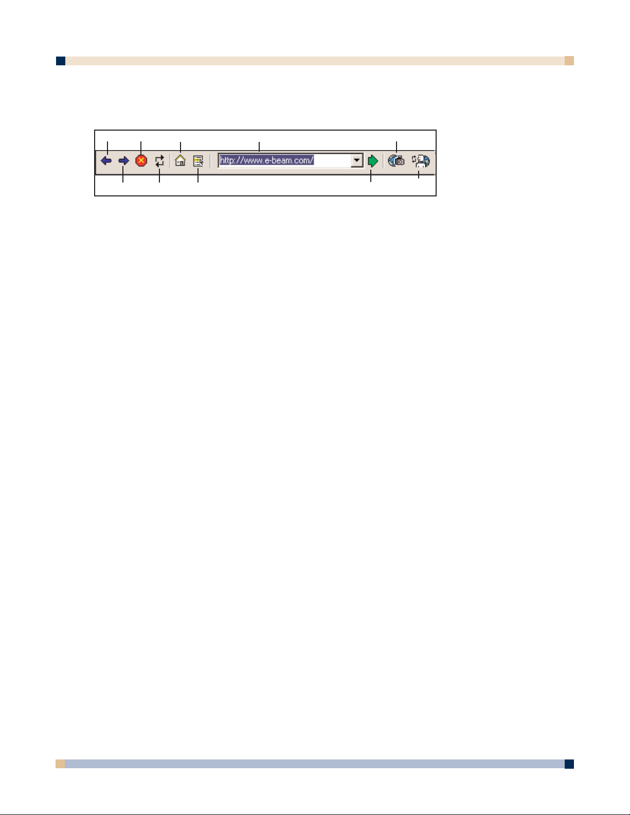
64
Web View Toolbar
The Web View toolbar contains the following controls:
Back Displays the previous viewed web page.
Back is disabled while you have viewed only one web page.
Forward Return to the web page you were viewing before you clicked
Back.
Forward
is enabled only when you have used the Back
button.
Stop Stops loading a web page.
Refresh Reloads the current web page.
Home Opens the Home page.
When you are using eBeam Software, eBeam’s web page is
the home page. To set your home page, see
Web Tour
Setup.
Favorites Displays your list of favorite websites. The addresses are
gathered from your Microsoft
®
Windows®Favorites directory.
Web Page URL Displays the URL of the current web page as a pull-down
menu. To go to a new web page, type in a new URL or
select a URL from the pull-down list, and then click Go.
Snapshot Takes a snapshot of the web page currently shown in the
Web View and loads it into the background of a new page in
your meeting. This feature is especially useful for building
presentations, because once the web page has been pulled in
to a background image, you can annotate it using the
Annotation Tools.
Go Opens the web page listed in the Web Page URL pull-down
menu.
Update Synchronizes the other participants to the current web page.
Participants This feature is available to the host once the Synchronize
Participants button has been clicked.
Web Tour Setup
You can set the Web Tour home page and clear your history list from Web Tour Setup.
Web Tour Setup is accessed by choosing Setup from the Edit menu, and selecting the Web
Tour Setup
tab.
OPERATOR’S GUIDE
3 M™ DIGITAL WALLDISPLAY
Back
Stop Home Web Page URL Snapshot
Forward Refresh
Favorites
Update
Participants
Go
Page 65

65
eBEAM SOFTWARE’S PROJECTION MODE
eBeam Software’s Projection mode turns your 3M Digital WallDisplay into a virtual touch
screen. Projection mode is best used as a presentation device, which allows you to open, close,
and show anything you need directly from the 3M Digital WallDisplay, instead of having to
walk between your computer and 3M Digital WallDisplay whenever you need to change something.
The eBeam system and the 3M Digital WallDisplay connect to your computer. The 3M Digital
WallDisplay projects your computer desktop onto the whiteboard and the eBeam system detects
when you touch the board, allowing a digital marker (using the Digital Mouse stylus insert) to
act as a virtual mouse which controls your computer’s desktop.
The purpose of Projection mode is to operate your computer directly from the 3M Digital
WallDisplay screen. In Projection mode, you can:
• Open, work in, and close applications.
• Draw freehand in painting and drawing applications.
• Run eBeam Software’s Meeting application directly from the whiteboard, including
sharing meetings while controlling the entire meeting directly from the whiteboard.
• Annotate over the top of your desktop using the
Projection Toolbar (see Annotating
Your Desktop).
In Projection mode, a tap of the digital marker on the 3M Digital WallDisplay screen simulates a
mouse click on your computer desktop. You can open, close, annotate, and save in an application from the whiteboard just as you would in front of your computer.
A Digital Mouse stylus is provided with your Digital White Board kit. The stylus is a plastic
insert which fits into any digital marker sleeve and allows you to use the digital marker as a
point-and-click device, instead of as a marker. This is useful during a presentation when you
wish to select different areas of the projected screen, without leaving dry-erase marker marks on
the whiteboard.
Projection Toolbar
The Projection Toolbar is used to control the most commonly used functions when in eBeam
Software’s Projection mode.
The following functions can be accessed from the
Projection Toolbar.
Annotate Your Desktop
Opens the Screen Annotation toolbar and allows
you to annotate your computer desktop. See
Annotating Your Desktop.
Calibrate Opens the Projection Mode calibration wizard.
Right Click Opens right-click menus or right-click functions
when using a digital marker in Projection mode.
OPERATOR’S GUIDE
3 M™ DIGITAL WALLDISPLAY
Calibrate
Annotate
Your
Desktop
Right
Click
On-Screen
Keyboard
Select
Mode
Hide
Projection
Toolbar
Page 66

66
To use, tap the Right Click button. The next time
you tap the 3M™ Digital WallDisplay with the digital
marker, eBeam Software will capture the tap as a rightclick, and will perform the appropriate right-click
function.
Select Mode Displays a mode select menu.
On-Screen Keyboard Opens the on-screen keyboard for use in Projection
mode.
This is supported only if your operating system has
a built-in on-screen keyboard and it is enabled.
Hide Projection Toolbar Closes/Hides the Projection Toolbar. eBeam
Software remains in Projection mode.
Annotating Your Desktop
eBeam Software’s Projection mode allows you to annotate your computer desktop. You open the
Screen Annotation toolbar from the Projection Toolbar, which can be accessed from eBeam’s
system tray menu.
It is important to understand that once the
Screen Annotation toolbar appears, eBeam Software
is in a screen annotation mode, which means the following:
•You can annotate anywhere on the desktop using tools from the
Screen Annotation
toolbar.
•You can
Save to a bitmap file, Print, or Copy to the system clipboard annotations
that you have created.
•You cannot open applications or use any of your computer’s other functions/features. This
is because the screen annotation mode takes a snapshot of your desktop and then puts the
snapshot on top of your computer desktop for you to draw on. You draw on the snapshot
layer, and the desktop itself remains protected under the layer. To exit screen annotation
mode and go back to using your computer’s other functions, you simply click the
Exit
button on the Screen Annotation toolbar.
The following tools are provided on the
Screen Annotation toolbar:
Pen Allows you to annotate your desktop freehand in any color supported
by your operating system. Clicking the arrow next to the Pen tool opens
a palette of pen options: Pen color, line thickness, and smooth lines.
Highlighter Allows you to highlight your desktop freehand in any color supported
by your operating system. Clicking the arrow next to the
Highlighter
tool opens a palette of highlighter options: Highlighter color, and line
thickness.
OPERATOR’S GUIDE
3 M™ DIGITAL WALLDISPLAY
Pen Eraser Select
Area
Redo Save Print
Highlighter
Shapes
Undo
Redo All
Copy
Exit
Page 67

67
Eraser Allows you to erase (from your desktop) any marks made with tools
from the
Screen Annotation toolbar. The eraser size can be selected
from the palette that appears when the arrow next to the Eraser tool is
clicked.
Shapes Allows you to use several different standard shapes (circle, square,
arrows, etc.) to annotate your desktop in any color supported by your
operating system. Clicking the arrow next to the
Shapes tool opens a
palette of shape options: Select shape, color, line thickness, smooth
lines, and whether or not to make the shape semi-transparent. Semitransparent allows you to read text and see lines through the shape
lines.
Select Area Allows you to draw a selection rectangle around an area on the desktop
which can then be saved, copied, or printed using the
Save, Copy, or
Print tools from the Screen Annotation toolbar.
Undo Erases the previous annotation. It is possible to undo until all annota-
tions have been removed.
Redo Redoes the last undone annotation. In the case of multiple undos, it is
possible to redo back to the final annotation on the desktop. Once the
next new annotation occurs,
Redo is disabled.
Redo is available when Undo was previously clicked.
Redo All Returns all previous undone annotations to the desktop. Once the next
new annotation occurs, Redo All is disabled.
Redo All is available when Undo was previously clicked.
Save Saves either the entire desktop or the selected area of the desktop
to a bitmap file.
A
Save option menu can be accessed by clicking the arrow attached to
the Save tool. If you have previously used the Select Area tool to
outline an area on your desktop, then the option to Save Selected
Area...
is the default choice from the menu, and only the selected
area is saved to file. If you have not outlined an area, then the
default is to Save Whole Screen... which saves the entire displayed
desktop to file.
Each time
Save is clicked, the standard Save As dialog box opens
allowing you to enter a meeting name and select the folder location.
Copy Copies either the entire desktop, or the selected area of the desktop
to your operating system’s clipboard. Data copied to the operating
system’s clipboard can later be pasted to other applications, such as
Paint, Word, etc.
A
Copy option menu can be accessed by clicking the arrow
attached to the Copy tool. If you have previously used the Select
Area tool to outline an area on your desktop, then the option to
Copy Selected Area to Clipboard is the default choice from the
menu, and only the selected area is copied to the operating system’s
clipboard. If you have not outlined an area, then the default is to
OPERATOR’S GUIDE
3 M™ DIGITAL WALLDISPLAY
Page 68

68
Copy Whole Screen to Clipboard which copies the entire displayed
desktop to the operating system’s clipboard.
Print Prints either the entire desktop or the selected area of the desktop
to a printer that you select. The printer must already be set up on
your operating system.
A
Print option menu can be accessed by clicking the arrow attached
to the Print tool. If you have previously used the Select Area tool
to outline an area on your desktop, then the option to Print
Selected Area...
is the default choice from the menu, and only the
selected area is printed. If you have not outlined an area, then the
default is to Print Whole Screen... which prints the entire displayed
desktop.
Exit Closes screen annotation mode, hides the Screen Annotation toolbar,
and returns eBeam Software to the standard Projection mode. Before
screen annotation mode closes, a message dialog box appears that
informs you that all annotations will be lost. If necessary, click
No
and use the Save, Copy, and Print tools to save your annotations.
Otherwise, click
Yes to return to eBeam Software’s Projection mode.
eBeam’s System Tray Menu
The eBeam Software menu appears as an icon in the system tray even when you are not using
eBeam Software. The following menu items are offered from the
system tray:
Capture from Whiteboard Puts eBeam Software in Whiteboard mode and
launches eBeam Software’s Meeting application used to
collect whiteboard data. See
Whiteboard Mode.
Capture from Flipchart (Not available on 3M™ Digital WallDisplay)
Use with Projector Puts eBeam Software in Projection mode. Your digital
marker now acts as a virtual mouse. See Projection
Mode
.
Disable System Disconnects eBeam Software from the hardware, free
ing the communication port on your computer. You can
still use eBeam Software’s Meeting application. When
the hardware is disconnected (or cannot be detected),
you will see a red line through the eBeam icon in the
system tray. See Icons That Represent a Mode.
Projection Toolbar Provides access to all Projection mode functions.
When eBeam Software is in Projection mode, the
Projection Toolbar provides access to all Projection
mode functions. See Projection Toolbar.
A check mark next to
Show Projection Toolbar indi-
cates that the toolbar is displayed. Also can be used to
access the
Annotating Your Desktop features.
Show On-Screen Keyboard Displays On-Screen Keyboard menu. If an on-screen
keyboard is supported and installed on your operating
system, the On-Screen Keyboard menu option causes
the
On-Screen Keyboard to be displayed and allows it
to be used in Projection mode.
OPERATOR’S GUIDE
3 M™ DIGITAL WALLDISPLAY
Page 69

69
Projection Mode Settings... Opens the Projection Setup dialog box. This dialog
box allows you to turn on/off various warning
messages.
Calibrate Projection Area... Initiates the Projection mode calibration wizard.
System Setup See Setup.
Detect System Attempts to detect the hardware.
Calibrate Capture Area Opens the hardware calibration wizard.
Help Opens the eBeam Software Help system.
Exit Completely closes down eBeam Software and removes
the eBeam icon from the system tray.
OPERATOR’S GUIDE
3 M™ DIGITAL WALLDISPLAY
Page 70

70
OPERATOR’S GUIDE
3 M™ DIGITAL WALLDISPLAY
3M™ DIGITAL WALLDISPLAY TROUBLESHOOTING
COMMON PROBLEMS AND SOLUTIONS
Continued on next page
Symptom
Power cannot be
turned on.
No picture or
sound.
The lamp will not
ignite or has
turned off.
The projection
arm opens, then
closes.
Sound is heard
with no picture.
Picture is
displayed with no
sound.
Picture is dark.
Cause
The power cord is disconnected.
The Master Power Switch is not
turned on.
The arm facade is not in place.
The desired input source is not
selected.
The cables from the input source are
not connected.
The input source is not turned on or
not displaying an image. (e.g. If a
notebook computer, the external
monitor port is not turned on.)
The internal temperature is too high.
The lamp has reached maximum life or
has prematurely failed.
The lamp will not ignite.
The VGA/Video cables are not
connected.
The VGA/Video/Audio cables are
connected to the wrong input.
The VGA/Video cables are not
connected.
The audio cables are connected to the
wrong input.
The volume is set to Minimum.
The
Mute is on.
The
Colorful—Bright setting must be
adjusted.
The lamp needs to be replaced.
Solution
Insert the power cord into an AC
socket.
Turn on the
Master Power Switch.
Make sure the arm facade is in
place.
Press the remote control Input
button to select a desired input
source.
Connect the cable to correct input
source.
Turn on input source.
Clear blocked ventilation holes.
Replace lamp.
Replace lamp.
Connect the cables to the correct
input source.
Connect the cables to the correct
input source.
Turn up
Volume.
Turn off Mute.
Adjust
Colorful—Bright slider
setting.
Replace lamp.
Page 71

71
OPERATOR’S GUIDE
3 M™ DIGITAL WALLDISPLAY
COMMON PROBLEMS AND SOLUTIONS, continued
ONSCREEN MESSAGES
Symptom
Desired input
source cannot be
detected.
The remote
control does not
work.
The menu system
will not display.
Cause
The input source is not active. Asignal
must be present for the input to be
selected.
The input device (e.g. computer, VHS
player, etc.) is not turned on.
The remote control is not facing the
remote control sensor.
The remote control is too far from the
sensor.
An obstruction is between the remote
control and the sensor.
The remote control’s batteries are
exhausted.
The menu system will not display
without an input source displayed.
Solution
Connect an active input source to
unit.
Turn on input source.
Face the remote control toward the
remote control sensor.
Operate the remote control within 5
meters.
Remove obstacle.
Replace batteries.
Connect an active input source to
unit.
Message
No input is detected.
Please change the lamp. After replacing lamp,
reset the lamp timer.
Please change the lamp. After replacing lamp,
reset the lamp timer.
There are 20 hours of lamp life remaining.
Please change the lamp.
The WallDisplay will shut off in 10 minutes.
Meaning
3M Digital WallDisplay is not receiving a signal
from an external source. Check the cable
connections and verify power is on and external
source is working.
The lamp has 1900 hours on it and needs to be
changed.
The lamp has 1980 hours on it and needs to be
changed.
When the lamp has 2000 hours or more on it,
the message will flash, and the power will turn
off after 10 minutes.
Page 72

72
OPERATOR’S GUIDE
3 M™ DIGITAL WALLDISPLAY
eBEAM TROUBLESHOOTING
Troubleshooting provides solutions for known issues with the eBeam system. This section covers
the Microsoft®Windows®versions of eBeam Software.
eBeam Hardware Detection/Use
Message
“eBeam not found.
Check connection
cable and power
supply.”
(This message might
appear at application
startup, or during the
course of a meeting.)
Status Line Message.
“Could not autodetect
eBeam Hardware.” or
“Could not connect to
eBeam Hardware on
X.” (where X is a port)
(This message would
most likely occur
when you have
selected
Cancel from
the eBeam not found
message dialog box.)
“The eBeam hardware is currently used
by Projection mode.
Would you like to use
the eBeam hardware
for this application?”
(This message might
appear at application
startup or after selecting
Whiteboard
Mode.)
eBeam
Software
Software
Software
Try the following:
• First check the hardware for your system as described,
and then click Cancel.
• See Unable to Detect the Hardware.
• Do you have more than one copy of eBeam Software
installed on your computer? If so, the other copy may be
running and have control of the port. Shut down the
other copy. We recommend that old versions of eBeam
Software be uninstalled from your computer.
• Exit the eBeam Software’s Meeting application and
restart it.
• Check that the eraser is not resting on the eraser pad.
• If you are using a Serial-to-USB connector, follow the
manufacturer’s setup instructions.
• See
“eBeam not found.” Check connection cable and
power supply. (This message might appear at application startup or during the course of a meeting.)
• See Unable to Detect the Hardware.
• Message displayed if you are trying to open or switch to
eBeam Software’s Meeting application from Projection
mode.
Page 73

3 M™ DIGITAL WALLDISPLAY
Network Connection/Shared Meetings
Problem
To share a meeting,
the eBeam Hardware
must be connected
and detected.”
(This message
appears when you
choose Shared
Meeting.)
Unable to share or
join a meeting over
the EFI meeting
server.
Using a cable modem
or DSL and unable to
share or join a meeting over the EFI meeting server.
Unable to see shared
meeting names in the
Join Meeting dialog
box.
eBeam
Software
Software
Software
Software
Try the following:
•To serve as the meeting host, your computer must be
attached to the eBeam Hardware. See Hosting/Sharing
a Meeting.
• If you are attempting to share a meeting, make sure that
you have the eBeam Hardware connected. See
Hosting/Sharing a Meeting.
• If your network/Internet connection is behind a firewall or
proxy server, you will have to set up the proxy server.
See Proxy Server Setup.
• If you are attempting to share a meeting, make sure that
you have the eBeam Hardware connected. See
Hosting/Sharing a Meeting.
• If your network/Internet connection is behind a firewall or
proxy server, you will have to set up the proxy server.
See Proxy Server Setup.
Even if you think you aren’t behind a proxy server/firewall, you
might be. Your ISP might have a firewall set up, causing this
problem. Try:
• Add a new server (see Adding a Meeting Server) with
a DNS: meetings.e-beam.com, and port: 443.
• This option is only available in version 2.1 and later.
Newer versions of the software automatically attempt to
connect through port 443, but it may be necessary to
manually set up the server as described previously.
•When the meeting host shares the meeting through the
Share Meeting dialog box (see Hosting/Sharing a
Meeting), they can select whether or not to publish the
meeting name. if the meeting name is published, then it
will show up in the Join Meeting dialog box. if the meet
ing name is not published, then other meeting partici
pants must manually type the meeting name into the
meeting name text box.
•To publish the meeting name, make sure that the
Publish meeting name check box in the Share
Meeting dialog box is checked.
• Does your intranet have a proxy server/firewall? Most
intranets do. If you have not done so, enable your proxy
server. See Proxy Server Setup.
How to set up the
proxy server?
Software
OPERATOR’S GUIDE
• See Proxy Server Setup.
73
Page 74

74
OPERATOR’S GUIDE
3 M™ DIGITAL WALLDISPLAY
Problem
Software states that
the eBeam hardware
is detected, but writing does not appear
in eBeam Software’s
Meeting application
Active Page.
Software is missing
many of the strokes
written with the digital
marker.
Digital marker strokes
are shown in eBeam
Software’s Meeting
application in the
wrong color.
Digital marker strokes
made at the bottom of
the whiteboard do not
appear in eBeam
Software’s Meeting
application.
eBeam
Hardware
Software
Hardware
Hardware
Software
Hardware
Try the following:
• Press the digital marker down on the whiteboard. If you
do not hear a faint buzzing, replace the batteries.
•Try another digital marker. If the other digital marker
works, replace the batteries in the digital marker sleeve
that does not work.
• Make sure you are not holding the sleeve too close to
the tip of the digital marker. This blocks the signal.
• Choose
eBeam Hardware > Detect eBeam Hardware
from the eBeam Software’s Meeting application Tools
menu and then check the status line. If it states that the
hardware is not detected, see Manually Detecting the
eBeam Hardware
.
• Press the digital marker down on the whiteboard. If you
do not hear a faint buzzing, replace the batteries.
• Make sure you are not holding the sleeve too close to
the tip of the digital marker. This blocks the signal.
• Make sure that you are pressing the digital marker firmly
against the 3M Digital WallDisplay when you write. The
marker is designed to write with a normal amount of
pressure by the writer; however, it is possible to write so
softly that the marker does not send out a signal.
• Make sure you are using the correct color digital marker
sleeve. The color of the digital marker sleeve is shown
on a color ring located near the tip of the digital marker.
• Check the color set for the sleeve in the Sleeve Settings
dialog box (see Setting Pen Colors/Line Thickness). It
is possible to set a different color in the software for any
eBeam digital marker.
• Press the digital marker down firmly on the whiteboard.
If you do not hear a faint buzzing noise, replace the batteries.
• Make sure you are not holding the digital marker too
close to the tip. This blocks the signal.
•Make sure that you are pressing the marker firmly
against the whiteboard when you write. The marker was
designed to write with a normal amount of pressure by
the writer; however, it is possible to write so softly that
the marker does not send out a signal.
Writing Data/Capture
Continued on next page
Page 75
75
OPERATOR’S GUIDE
3 M™ DIGITAL WALLDISPLAY
Problem
Digital marker strokes
made at the bottom of
the whiteboard do not
appear in eBeam
Software’s Meeting
application.
Digital eraser does
not erase.
eBeam
Software
Hardware
Software
Try the following:
• Make sure you are writing within the calibrated image
area on the whiteboard.
• Press the eraser down on the whiteboard. If you do not
hear a faint buzzing noise, replace the batteries.
• Choose
eBeam Hardware > Detect eBeam Hardware
from the eBeam Software’s Meeting application Tools
menu and then check the status line.
Writing Data/Capture, continued
Page 76

76
OPERATOR’S GUIDE
3 M™ DIGITAL WALLDISPLAY
Problem
Applet does not load.
While using iVISTA,
the applet does not
load.
Unable to see shared
meeting names in the
Join Meeting dialog
box.
eBeam
Software
Software
Software
Try the following:
Microsoft
®
Internet Explorer
®
• In Internet Explorer, go to Tools > Internet Options.
Click the
Security tab, and then click Restricted Sites.
Click the Custom Level button, and then scroll down
the list to Microsoft VM. Make sure that Disable Java
is not selected. Attempt to open the applet again.
• In Internet Explorer, go to
Tools > Internet Options,
and click the Delete Files button. Attempt to open the
applet.
Netscape
®
• In Netscape, go to File (or Edit) > Preferences. Click
the Advanced option, and make sure that Enable Java
is checked.
• In Netscape, go to
File (or Edit) > Preferences. Click
the Advanced option, and then click Cache Click both
the Clear Memory Cache and Clear Disk Cache
buttons. Attempt to reopen the applet.
iVISTA and eBeam Software’s Meeting application both use
port 80 as the default connection port. Try hosting the eBeam
meeting over port 81 or some other port value. Try:
• From the
Share Meeting dialog box (see
Hosting/Sharing a Meeting), select Use my PC to
host this meeting
, then type 81 in the Port text box.
• Participants attempting to log in to the meeting should
type http://meeting_name:81, where meeting_name is
the name entered in the Meeting Name text box, and 81
is the port value you have entered.
•When the meeting host shares the meeting through the
Share Meeting dialog box (see Hosting/Sharing a
Meeting), they can select whether to publish the meet-
ing name. If the meeting name is published, it will show
up in the Join Meeting dialog box. If the meeting name
is not published, then other meeting participants must
manually type the meeting name into the
Meeting Name
text box.
•To publish the meeting name, make sure that the meet
ing host checked the
Publish Meeting Name check box
in the Share Meeting dialog box.
• Does your intranet have a proxy server/firewall? Most
intranets do. If you have not done so, enable your proxy
server. See
Proxy Server Setup.
EFI Meeting Applet
Page 77

77
OPERATOR’S GUIDE
3 M™ DIGITAL WALLDISPLAY
Problem
Microsoft ®Excel
®
spreadsheet did not
load properly.
Background image
quality is bad.
eBeam
Software
Software
Try the following:
• Is there a graph in the spreadsheet? eBeam Software’s
Meeting application cannot import a spreadsheet
containing a graph.
• See
Loading an Excel Spreadsheet as a Background
Image.
• Background images that are sent to the applet meeting
viewer are highly compressed to make the image faster
to download. Using the eBeam Software’s Meeting application is better if you wish for background images to be
easy to view.
Background Images
Page 78

78
OPERATOR’S GUIDE
3 M™ DIGITAL WALLDISPLAY
SERVICE INFORMATION
PARTS AND ACCESSORIES
Description Part Number
Power Cord (EU) 78-8131-0004-3
Power Cord (US) 78-8131-0005-0
Power Cord (UK) 78-8131-0003-5
Serial Mouse Cable 26-1015-0423-6
USB Cable 26-1015-0424-4
VGA Cable 26-1015-0425-1
DVI-D Cable 26-1015-0418-6
PC Audio Cable 26-1015-0420-2
S-Video Cable 26-1015-0422-8
Replacement Lamp Kit 78-6969-9377-9
Remote Control Unit 78-8121-0330-3
Macintosh Adapter 26-1015-0419-4
3-Conductor Video/Audio Cable 26-1015-0421-0
Operator’s Guide CD-ROM 78-6970-9074-0
Quick Start Guide for 3M Digital WallDisplay 78-6970-9075-0
Quick Start Guide for 3M Digital WallDisplay with
Ideaboard 78-6970-9117-7
Quick Start Guide for eBeam Software 78-6970-8516-1
ORDERING PARTS OR GETTING INFORMATION
For product information, product assistance, service information, or to order accessories,
please contact 3M Customer Service at the following numbers:
• In U.S. or Canada:
1-800-328-1371
• In other locations, contact your 3M Sales office.
The contents of this manual are subject to change without prior notice.
3M assumes no responsibility for the infringement of special rights of a third party or other rights that
may arise out of the information contained in this manual.
Reproduction of this manual in any form without prior permission is strictly prohibited.
Page 79

79
OPERATOR’S GUIDE
3 M™ DIGITAL WALLDISPLAY
APPENDIX
3M DIGITAL WALLDISPLAY SPECIFICATIONS
eziSyalpsiDaeraelbaweivlanogaiD˝06
oitaRtcepsAyalpsiD3:4
metsySyalpsiD ygolonhcetstnemurtsnIsaxeT™PLD,pihCelgniS
eziSlanogaiDpihChcni7.0
pihCPLD
slexiPforebmuNslexip867x4201
roloCroloclluftib-42
oitaRtsartnoC1:051
epyT)erusserPhgiH-repuS(PHS
pmaL
efiLsruoH0002
snoisnemiD
thgieW.sbl58.xorppA
ytilibitapmoCoediV MACES,M-LAP,N-LAP,LAP,34.4CSTN,CSTN
ytilibitapmoCoediVretupmoCAGXSotAGV
noitalumEesuoM BSUdna,BDA,esuomlairesCP
tupnIretupmoC
slangiS
tuptuO/tupnI
lanimreT
slangistupnioediVnip-4NIDiniM:oediV-S
tuOoiduAskcajACR
troPlortnoC232-SRbuS-Dnip-9
troPnoitalumEesuoMbuS-Dnip-9
)srekaepsot(reifilpmAlennahcrepttaW81
metsySoiduA
srekaepSsmhO8,xaMsttaW04
D˝0.7xW˝2.35xH˝6.74
)mm971xmm0531xmm8021(
buS-Dinimnip-51:BGRgolanA
)ylnolatigid(D-IVD:BGRlatigiD
kcaj-inimoeretsmm5.3:oiduA
stnemeriuqeRrewoP .xaMsttaW004,zH06/05,CAV042~001
Page 80

80
OPERATOR’S GUIDE
3 M™ DIGITAL WALLDISPLAY
INPUT/OUTPUT SIGNAL SPECIFICATIONS
COMPUTER COMPATIBILITY
XGA 60Hz VGA 75Hz
XGA 70Hz VGA 85Hz
XGA 75Hz SXGA 60Hz
XGA 85Hz DOS TEXT 640x400
SVGA 60Hz Mac 16˝ 832x624
SVGA 72Hz Mac 13˝ VGA
SVGA 75Hz Mac LC VGA
SVGA 85Hz VESA 350 640x350
SVGA 56Hz VESA 720x400
VGA 60Hz VESA 1280x960 60Hz
VGA 72Hz VESA 1152x864
langiSoediV
langiScnySlatnoziroH
retupmoC
oediV-S
oediV
langiSoediVsmhO57,p-pV0.1
langiScnySlacitreV
langiScnySetisopmoCleveLLTT
langiStupnIoiduA
langiStuptuOoiduAsmhOk1,smrVm002~0
langiStupnIoiduAsmhOk02,smrVm002
)ytiralop
)ytiralop
)p-pV0.3
smhO57
smhO
smhO57,p-pV7.0golanA
)ytiralopevitisop(noitanimret
evitagen/evitisop(leveLLTT
evitagen/evitisop(leveLLTT
xaM(smhOk02,smrVm002
,p-pV0.1:langisecnanimuL
:langisecnanimorhC
57,)tsrubroloc(p-pV682.0
Page 81

81
OPERATOR’S GUIDE
3 M™ DIGITAL WALLDISPLAY
PRINTER COMPATIBILITY
Apollo P-2200 HP LaserJet 1100
1120
Fiery X2e 4050
4500
HP Business Inkjet 2250TN 4L
4M Plus
HP Color LaserJet 4550 5000
5L
HP DeskJet 340 5si
350 6MP
400 8100
420 8150
500 IIID
540
600 HP OfficeJet 590
610 630
630 685
648 G55
648C G85
694 K60
840 K80
842 R65
842C T45
880 Pro 1175CSE
895
932 HP PhotoSmart 1215
932C
940
950
952C
960 HP PSC 500
970
970 Cse Hitachi DDS 50/62
990
990 Cse Konica 7040
1120
1125
1220
1220C
1218
P1000
P1100
Page 82

Important Notice
All statements, technical information, and recommendations related to 3M’s products are based on information believed to be
reliable, but the accuracy or completeness is not guaranteed. Before using this product, you must evaluate it and determine if it
is suitable for your intended application. You assume all risks and liability associated with such use. Any statements related to
the product which are not contained in 3M’s current publications, or any contrary statements contained on your purchase order
shall have no force or effect unless expressly set forth in a written agreement signed by an authorized officer of 3M.
Avis Important
Toutes les déclarations, l’information d’ordre technique et les recommendations afférentes aux produits 3M sont fondées sur
des renseignements supposés exacts, mais la précision ou l’intégralité n’est pas garantie. Avant d’utiliser ce produit, vous devez
l’évaluer afin de déterminer s’il est adapté aux applications que vous avez l’intention d’utiliser. Vous acceptez tous les risques
et la responsabilité associés à une telle utilisation. Toutes les déclarations concernant le produit qui ne sont pas incluses dans
les publications actuelles de 3M et toutes les déclarations contradictoires qui sont incluses sur votre bon de commande seront
sans effet sauf accord explicite par écrit avec un cadre agréé de 3M.
Wichtiger Hinweis
Alle Angaben, technischen Informationen und Empfehlungen, die sich auf 3M-Produkte beziehen, sind nach bestem Wissen
korrekt und zuverlässig, jedoch können wir keine Gewähr übernehmen. Vor der Anschaffung dieses Produkts sollten Sie sich
davon überzeugen, das es für den vorgesehenen Einsatz tauglich ist. Alle aus der Verwendung des Produkts entstehenden
Risiken und jegliche Haftung liegt bei Ihnen. Jegliche sich auf das Produkt beziehende Aussagen, die nicht aus einer aktuellen
Veröffentlichung von 3M stammen bzw. jegliche im Kaufauftrag enthaltene gegensätzliche Aussagen sind ohne ausdrückliche
schriftliche Genehmigung durch einen autorisierten Vertreter von 3M nicht gültig bzw. ohne Wirkung.
Aviso Importante
Todas las declaraciones, información técnica y recomendaciones relacionadas con los productos 3M está basada en información que se cree fiable, pero la preción o lo completo de éstas no está garantizado. Antes de utilizar este producto debe evaluarlo y determinar si es adecuado para su aplicación. Usted asume todos los riesgos y la responsabilidades asociadas con dicho
uso. Cualquier afirmación relacionada con el producto que no se encuentre en las publicaciones actuales de 3M, o cualquier
afirmación contraria incluida en su orden de compra, carecerá de vigencia y efecto si no ha sido acordada expresamente, por
escrito, por un funcionario autorizado de 3M.
Avviso importante
Tutte le dichiarazioni, le informazioni tecniche e i consigli relativi a prodotti 3M si basano su informazioni ritenute affidabili,
ma la loro accuratezza o completezza non sono garantite. Prima di utilizzare questo prodotto, è necessario valutarlo e determinarne l’idoneità per l’applicazione prevista. L’utente si assume tutti i rischi e le responsabilità associati a tale utilizzo. Qualsiasi
dichiarazione relativa al prodotto che non sia riportata nelle pubblicazioni correnti della 3M o qualsiasi dichiarazione opposta
riportata sull’ordine d’acquisto, non costituirà obbligo e non avrà alcun effetto, tranne se concordato esplicitamente con autorizzazione scritta emessa da un rappresentante ufficiale della 3M.
Litho in USA
Copyright © 2003 3M
All Rights Reserved
78-6970-9074-0 Rev. C
3M Austin Center
Building A145-5N-01
6801 River Place Blvd.
Austin, TX 78726-9000
3M Canada
P.O. Box 5757
London, Ontario
N6A 4T1
3M Mexico, S.A. de C.V.
Apartado Postal 14-139
Mexico, D.F. 07000
Mexico
http://www.3M.com/walldisplay
3M Europe
Boulevard de l’Oise
95006 Cerge Pontoise Cedex
France
Copyright © 2002 3M
All Rights Reserved
78-6970-9074-0 Rev.
Litho in USA
 Loading...