

Page 1

Instructions and Parts List
Important
TM
3M-Matic
800r3 Type 29600
Random
Case Sealer
with
TM
AccuGlide
II
Safeguards
Read "Safety Labels", pages
3-6 and also operating
"Warnings", page 17
BEFORE INSTALLING
OR OPERATING THIS
EQUIPMENT.
Taping Heads
Serial No.
For Reference, record taping head(s) serial number(s) here.
3M Packaging Systems Division
3M Center, Building 220-8W-01
St. Paul, MN 55144-1000
Important
It is recommended you
immediately order the
spare parts listed on
page 37. These parts
are expected to wear
through normal use
and should be kept on
hand to minimize
production delays.
"3M-Matic" and "AccuGlide" are Trademarks
of 3M, St. Paul, MN 55144-1000
Printed in U.S.A.
© 3M 1998 44-0009-1898-5(A108.0)
Page 2

Replacement Parts and Service Information
To Our Customers:
This is the 3M-Matic™/AccuGlide™/Scotch™ brand equipment you
ordered. It has been set up and tested in the factory with "Scotch" brand
tapes. If technical assistance or replacement parts are needed, call or Fax
the appropriate number listed below.
Included with each machine is an Instructions and Parts List manual.
T echnical Assistance:
3M-Matic™ Helpline – 1-800/328 1390. Please provide the customer support
coordinator with the machine number, machine type/model and serial number.
If you have a technical question that does not require an immediate response,
you may Fax it to 715/381 0248.
Replacement Parts and Additional Manuals
Order parts by part number, part description and quantity required. Also,
when ordering parts and/or additional manuals, include machine name,
number and type. A parts order form is provided at the back of this manual.
3M/Tape Dispenser Parts
241 Venture Drive 1-800/344 9883
Amery, WI 54001-1325 FAX# 715/268 8153
Minimum billing on parts orders will be $25.00. Replacement part prices available on request.
$10.00 restocking charge per invoice on returned parts.
Note : Outside the U.S., contact the local 3M subsidiary for parts ordering information.
3M Packaging Systems Division
3M Center, Building 220-8W-01
St. Paul, MN 55144-1000
"3M-Matic", "AccuGlide" and “Scotch” are trademarks
of 3M, St. Paul, Minnesota 55144-1000
Printed in U.S.A.
© 3M 1999 44-0009-1851-4(E79.0)
Page 3

Replacement Parts And Service Information
To Our Customers:
This is the 3M-Matic™/AccuGlide™/Scotch™ brand equipment you
ordered. It has been set up and tested in the factory with "Scotch" brand
tapes. If any problems occur when operating this equipment, and you
desire a service call, or phone consultation, call, write or Fax the
appropriate number listed below.
Included with each machine is an Instructions and Parts List manual.
SERVICE, REPLACEMENT PARTS AND ADDITIONAL MANUALS
AVAILABLE DIRECT FROM:
Order parts by part number, part description and quantity required. Also, when
ordering parts and/or additional manuals, include machine name, number and
type.
3M Packaging Systems Division
3M Center, Building 220-8W-01
St. Paul, MN 55144-1000
1-800/328 1390
"3M-Matic", "AccuGlide" and “Scotch” are trademarks
of 3M, St. Paul, Minnesota 55144-1000
Printed in U.S.A.
© 3M 1999 44-0009-1852-2(D79.0)
Page 4

Instruction Manual
800r3 Random Case Sealer, Type 29600
This instruction manual is divided into two sections as follows:
Section I Includes all information related to installation, operation and parts for the case sealer.
Section II Includes specific information regarding the AccuGlide™ II STD 3 Inch Taping Heads.
Table of Contents Page
Section I – 800r3 Random Case Sealer
Intended Use..................................................................................................................................... 1
Equipment Warranty and Limited Remedy....................................................................................... 2
800r3 Contents ................................................................................................................................. 2
Important Safeguards ....................................................................................................................... 3 - 6
Specifications.................................................................................................................................... 7 - 9
Installation and Set-Up ..................................................................................................................... 10 - 12
Receiving and Handling....................................................................................... 10
Machine Set-Up ................................................................................................... 10 - 12
Packaging and Separate Parts .................................................................. 10
Outboard Tape Roll Mounting.................................................................... 11
Tape Leg Length........................................................................................ 11
Box Size Capacity of Case Sealer............................................................. 11
Pneumatic Connection............................................................................... 12
Electrical Connection and Controls ........................................................... 12
Initial Start-Up of Case Sealer ................................................................... 12
Operation .......................................................................................................................................... 13 - 18
Controls, Valves and Switches............................................................................ 14 - 16
Tape Loading/Threading ..................................................................................... 17
Box Sealing.......................................................................................................... 18
Box Jam............................................................................................................... 18
Maintenance ..................................................................................................................................... 19 - 22
Cleaning............................................................................................................... 19
Lubrication ........................................................................................................... 19
Drive Belts ........................................................................................................... 20 - 21
Circuit Breaker ..................................................................................................... 22
Knife Replacement, Taping Head ....................................................................... 22
Adjustments ..................................................................................................................................... 23
Drive Belt Tension ............................................................................................... 23
Taping Head Adjustments ................................................................................... 23
(Table of Content continued on next page)
i
Page 5

Table of Contents (Continued) Page
Special Set-Up Procedure ................................................................................................................ 24 - 25
Changing Tape Leg Length ................................................................................. 24
Box Height Range................................................................................................ 24 - 25
Troubleshooting ................................................................................................................................ 27 - 30
Operating Sequence......................................................................................................................... 31
Electrical Diagram............................................................................................................................. 32 - 33
Pneumatic Diagram .......................................................................................................................... 34 - 35
Parts and Service Information .......................................................................................................... 37
Options/Accessories ......................................................................................................................... 38
Replacement Parts Illustrations and Parts Lists.................................................. Yellow Section 39 - 69
Section II – AccuGlide™ II STD 3-Inch Taping Head
(See Section II for Table of Contents)
ii
Page 6
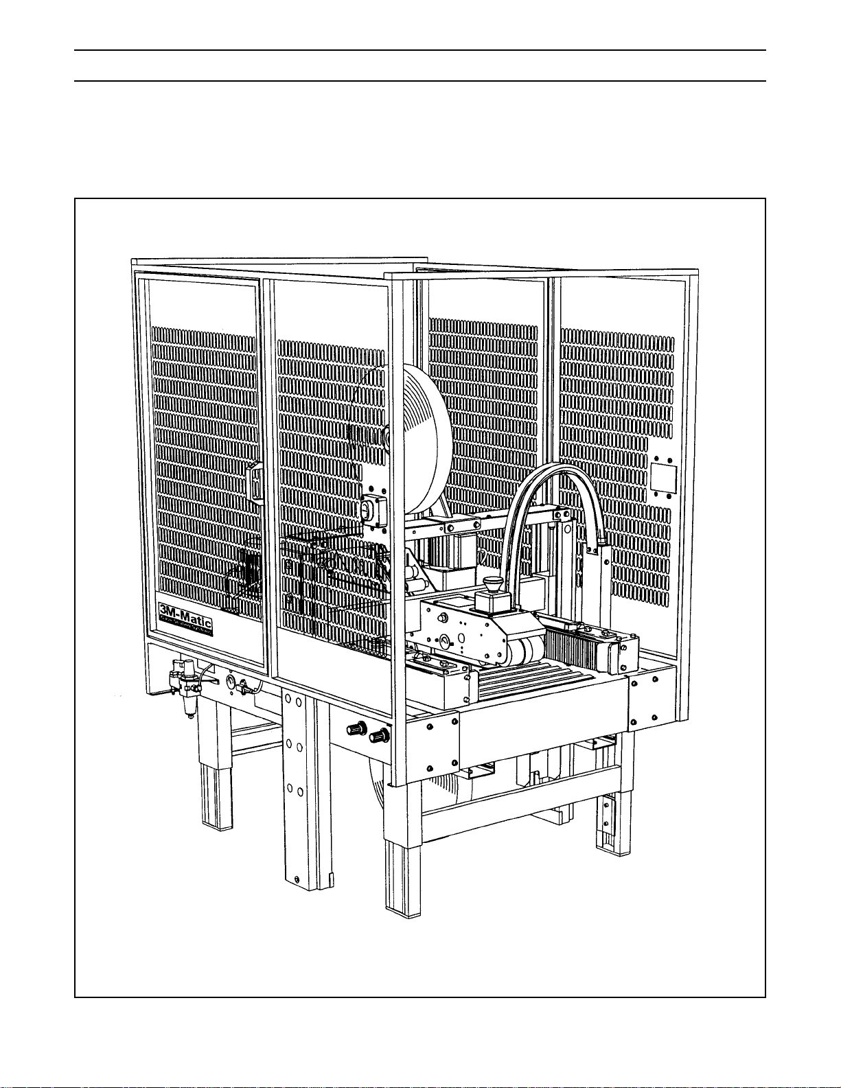
Intended Use
The intended use of the 3M-MaticTM 800r3 Random Case Sealer with AccuGlideTM II Taping Heads is to apply a
“C” clip of ScotchTM brand pressure-sensitive film box sealing tape to the top and bottom center seam of regular
slotted containers. The case sealer automatically adjusts to a wide range of box sizes (see "Specifications –
Box Weight and Size Capacities", page 8).
3M-MaticTM 800r3 Random Case Sealer, Type 29600
1
Page 7

Equipment Warranty and Limited Remedy: THE FOLLOWING WARRANTY IS MADE IN LIEU OF ALL
OTHER WARRANTIES, EXPRESS OR IMPLIED, INCLUDING, BUT NOT LIMITED TO, THE IMPLIED WARRANTY OF MERCHANTABILITY, THE IMPLIED WARRANTY OF FITNESS FOR A PARTICULAR PURPOSE
AND ANY IMPLIED WARRANTY ARISING OUT OF A COURSE OF DEALING, A CUSTOM OR USAGE OF
TRADE:
3M sells its 3M-Matic™ 800r3 Random Case Sealer, Type 29600 with the following warranties:
1. The drive belts and the taping head knives, springs and rollers will be free from all defects for ninety
(90) days after delivery.
2. All other taping head parts will be free from all defects for three (3) years after delivery.
3. All other parts will be free from all defects for two (2) years after delivery.
If any part is proved to be defective within its warranty period, then the exclusive remedy and 3M’s and seller’s
sole obligation shall be, at 3M’s option, to repair or replace the part, provided the defective part is returned
immediately to 3M’s factory or an authorized service station designated by 3M. A part will be presumed to have
become defective after its warranty period unless the part is received or 3M is notified of the problem no later
than five (5) calendar days after the warranty period. If 3M is unable to repair or replace the part within a
reasonable time, then 3M at its option, will replace the equipment or refund the purchase price. 3M shall have
no obligation to provide or pay for the labor required to install the repaired or replacement part. 3M shall have
no obligation to repair or replace (1) those parts failing due to operator misuse, carelessness, or due to any
accidental cause other than equipment failure, or (2) parts failing due to non-lubrication, inadequate cleaning,
improper operating environment, improper utilities or operator error.
Limitation of Liability: 3M and seller shall not be liable for direct, indirect, special, incidental or consequential
damages based upon breach of warranty, breach of contract, negligence, strict liability or any other legal
theory.
The foregoing Equipment Warranty and Limited Remedy and Limitation of Liability may be changed only by a
written agreement signed by authorized officers of 3M and seller.
800r3 Contents
(1) 800r3 Random Case Sealer, Type 29600
(1) Tool and Parts List
(1) Instruction and Parts Manual
ScotchTM, AccuGlideTM, and 3M-MaticTM are Trademarks of 3M, St. Paul, Minnesota 55144-1000
2
Page 8
Important Safeguards
This safety alert symbol identifies
important messages in this manual.
READ AND UNDERSTAND THEM BEFORE
INSTALLING OR OPERATING THIS
EQUIPMENT.
Important – In the event the following safety
labels are damaged or destroyed, they must be
replaced to ensure operator safety. A label
kit, part number 78-8113-6778-4 is available as
a stock item or individual labels can be ordered.
See Parts Illustration/List, Section I, pages 66
and 67.
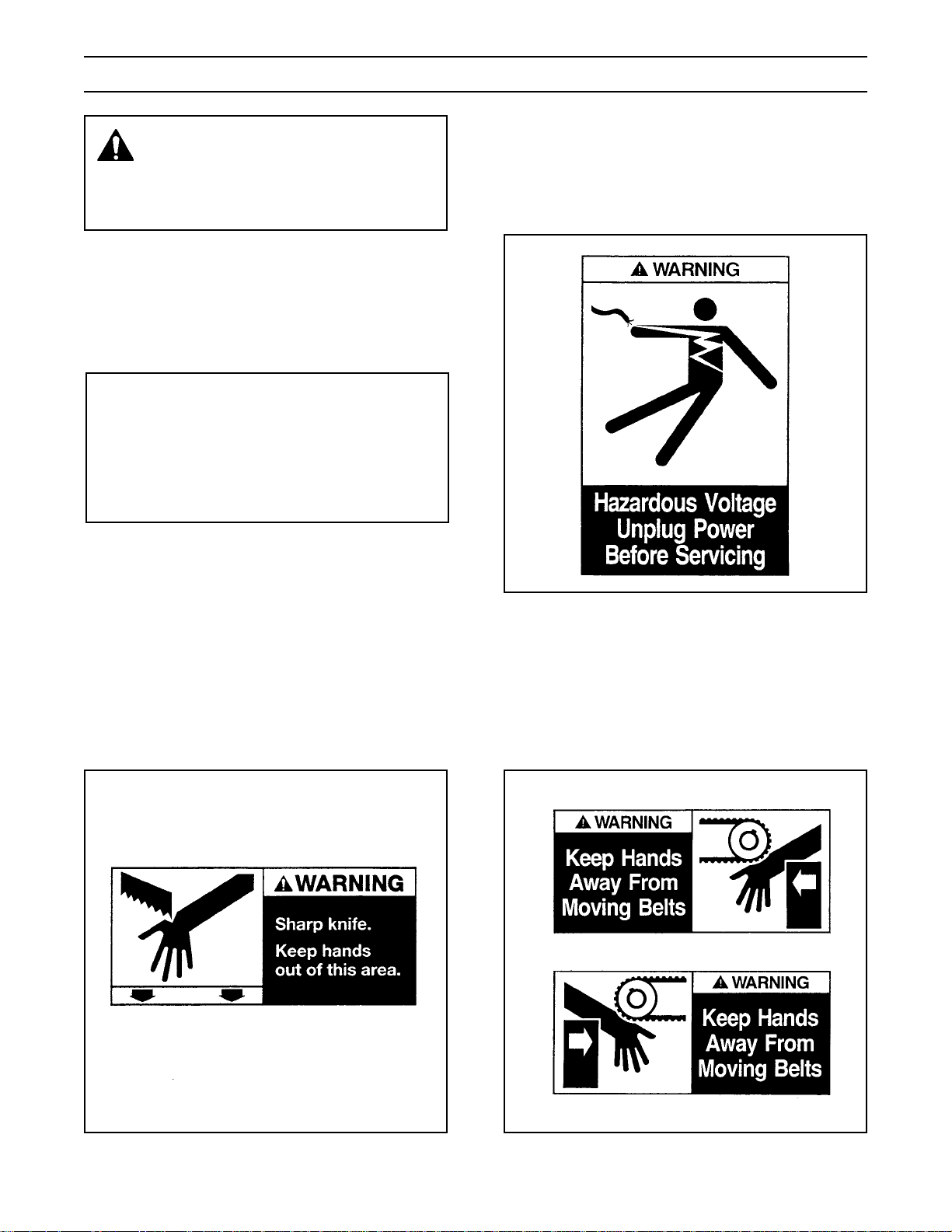
The "Warning - Hazardous Voltage" label, shown
in Figure 1-2, is attached to the electrical enclosure
on the lower right side of the machine frame. The
label warns service personnel to unplug the power
supply before attempting any service work on the
case sealer.
Two "Warning Sharp Knife" labels, shown in
Figure 1-1, are attached to both sides of the upper
assembly at the location of the cut-off knife on the
upper taping head. The labels warn operators and
service personnel of the very sharp knife used to cut
the tape at the end of the tape application.
Figure 1-2 – Electrical Warning Label
The two "Warning – Keep Away From Moving
Belts" labels, shown in Figure 1-3, are located on
each side of the top surface of the machine bed at
the infeed end. These labels warn operators and
service personnel to keep hands away from this
area when the drive belts are running.
Figure 1-1 – Knife Warning Label
Figure 1-3 – Hands Warning Label
3
Page 9
Important Safeguards (Continued)
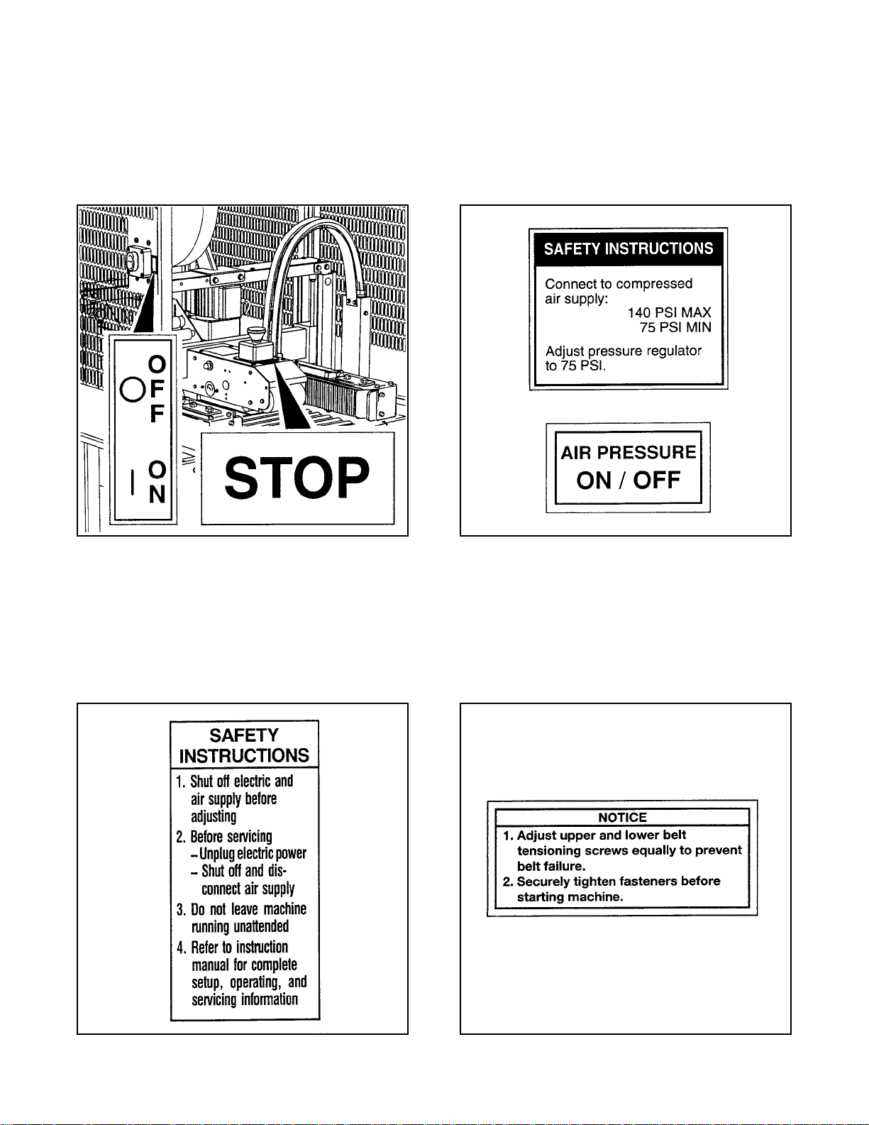
The "Stop" label, shown in Figure 1-4, is located in
front of the E-Stop switch and reminds operators
and casual personnel of the function of this switch.
In addition, an "On/Off" label is attached next to the
On/Off switch on the left machine guard at the
infeed end.
The "Safety Instructions" label, shown in
Figure 1-6, is attached to the frame next to the air
valve/regulator and reminds operator of correct air
pressure to use. The "On/Off" label reminds
operators of the location of the pneumatic On/Off
valve.
Figure 1-4 – Stop and On/Off Labels
The "Safety Instructions" label, shown in
Figure 1-5, is attached to the front of the upper
assembly. The label provides convenient safeguard
instructions for the operator and service personnel.
Figure 1-6 – Safety Instructions Label
Two "Operating Notice" labels, shown in
Figure 1-7, are located on the top, infeed end of
both drive belt assemblies. The labels remind
operators of correct belt adjustment procedures.
Figure 1-5 – Safety Instructions Label
Figure 1-7 – Operating Notice Label
4
Page 10
Important Safeguards (Continued)
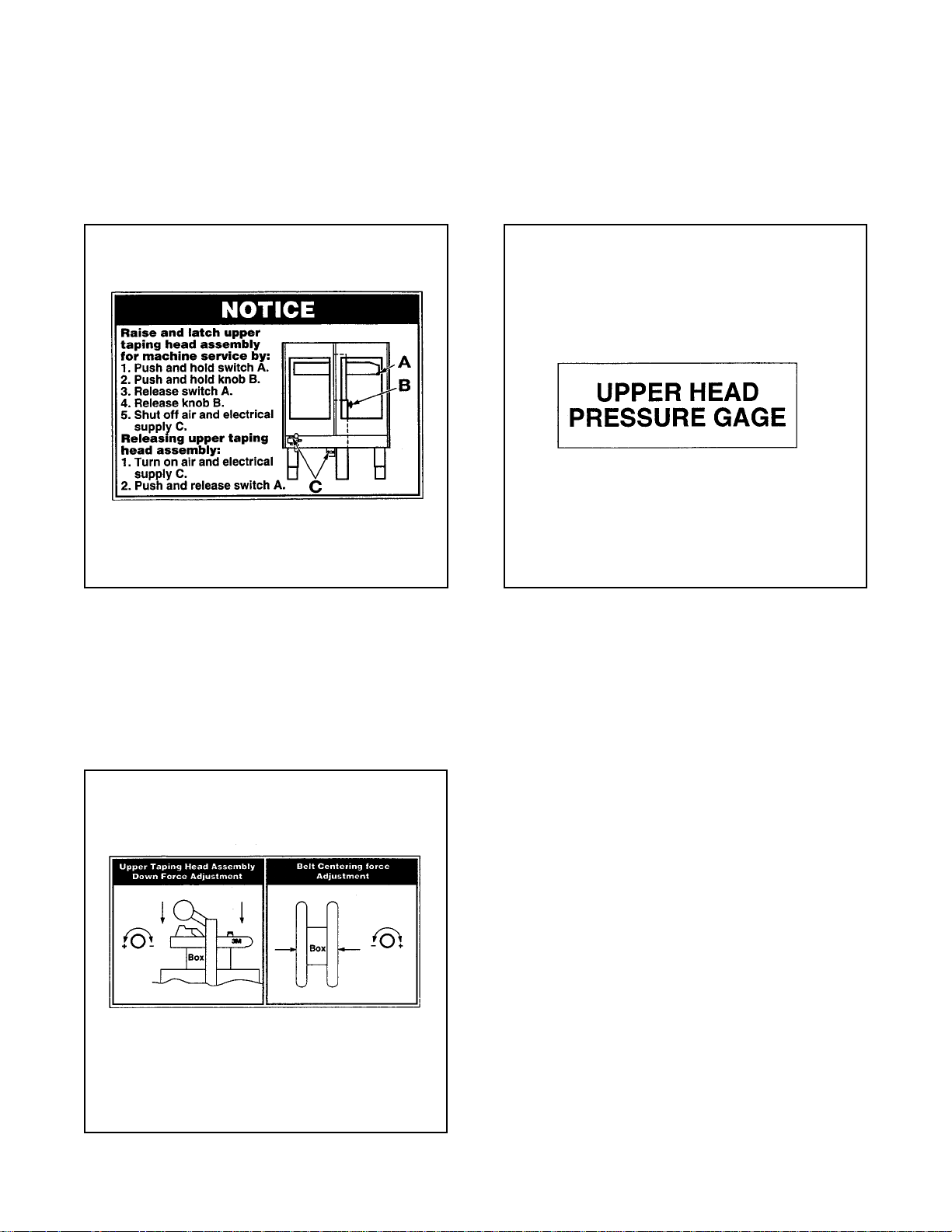
The "Raise/Latch" label, shown in Figure 1-8, is
attached to the upper, middle of the left machine
guard. The label provides quick reference
instructions for raising, latching and unlatching the
upper assembly.
The "Upper Head Pressure Gage" label, shown in
Figure 1-10, is attached to the upper assembly by
the air pressure gage.
Figure 1-8 – Raise/Latch Upper Assembly Label
The "Force Adjustment" label, shown in
Figure 1-9, is attached to the left side of the
machine frame at the infeed end, The label
provides force adjustment information for the upper
taping head assembly and belt centering.
Figure 1-10 –Air Pressure Gage Label
Figure 1-9 – Force Adjustment Label
5
Page 11

Important Safeguards (Continued)
The following two labels are located on the upper
and lower taping heads. Replacement part
numbers for these labels are listed below each
label.
The "Warning-Sharp Knife" label warns operators
and service personnel of the extremely sharp knife
used to cut the tape at the end of the box sealing
operation. The label, shown in Figure 1-11, is
located on the orange knife guard between the
applying roller assembly and the buffing roller
assembly. Never operate taping heads with knife
guard removed.
Before working with the taping heads or loading/
threading tape, refer to Figures 3-1 and 3-2 in
Section II to identify the knife location. Keep hands
out of these areas except as necessary to
service the upper taping heads or to load/thread
tape.
The "Tape Threading Label", shown in
Figure 1-12, is attached to the left side of both the
upper and lower taping heads. This label provides a
convenient tape threading diagram. More detailed
tape loading and threading information is provided
in this manual in the set-up procedure section.
Figure 1-11 – Knife Warning Label
Figure 1-12 – Tape Threading Label
6
Page 12

Specifications
1. Power Requirements:
Electrical – 115 VAC, 60 Hz, 3.8 A (440 watts)
Pneumatic – 6.5 bar gauge pressure [95 PSIG]
110 litre/min @ 21° C, 1.01 bar
[3.75 SCFM] at 15 boxes per
minute
The machine is equipped with two 1/6 HP
gearmotors and comes with a 2.4 meter [8 ft]
long standard neoprene covered power cord
and a grounded plug. Contact your 3M
Representative for power requirements not
listed above.
2. Operating Rate:
Up to 15 boxes per minute. Actual production
rate is dependent on box size, box size mix, and
operator dexterity.
Box drive belt speed is 24 m/m [78 FPM]
4. Tape:
ScotchTM brand pressure-sensitive film box
sealing tapes.
5. Tape Width:
48 mm [2.0 in] minimum to
72 mm [3.0 in] maximum
6. Tape Roll Diameter:
Up to 405 mm [16.0 in] maximum on a
76.2 mm [3.0 in] diameter core.
(Accommodates all system roll lengths of
Scotch
TM
brand film tapes.)
7. Tape Application Leg Length – Standard:
70 mm ± 6 mm [2.75 in ±.25 in]
Tape Application Leg Length – Optional:
(See "Special Set-Up Procedure", page 24)
3. Operating Conditions:
Use in dry, relatively clean environments at 4° to
50° C [40° to 120° F] with clean, dry, boxes.
Note – Machine should not be washed down or
subjected to conditions causing moisture
condensation on components.
50 mm ± 6 mm [2.00 in ±.25 in]
8. Box Board:
Style – regular slotted containers – RSC
125 to 275 P.S.I. bursting test, single wall or
double wall B or C flute.
(Specifications continued on next page)
7
Page 13

Specifications (Continued)
9. Box Weight and Size Capacities:
Weight
Maximum – up to 38.6 kg [85 pounds]
Minimum – contents must support top flaps and
weight must be sufficient to hold bottom flaps
fully closed.
Box Size
OUTER COLUMNS IN STANDARD POSITION
MINIMUM
Length – 205 mm [8.00 in]
Width – 133 mm [5.25 in]
Height – 127 mm [5.00 in]
MAXIMUM
Length – Not Limited
Width – 508 mm [20.0 in]
Height – 533 mm [21.0 in]
OUTER COLUMNS IN OPTIONAL RAISED
POSITION
Special modifications may be available for
carton sizes not listed above. Contact your 3M
Representative for information.
Note: The case sealer can accommodate most
boxes within the size range listed above. However,
if the box length (in direction of seal) to box height
ratio is .5 or less, then several boxes should be test
run to assure the proper machine performance.
DETERMINE THE BOX LIMITATIONS BY
COMPLETING THIS FORMULA:
Box Length In
Direction Of Seal Must Be Greater Than .5
Box Height
Any box ratio approaching this limitation should be
test run to assure performance.
MINIMUM
Length – 205 mm [8.00 in]
Width – 130 mm [5.25 in]
Height – 232 mm [9.12 in]
MAXIMUM
Length – Not Limited
Width – 508 mm [20.00 in]
Height – 644 mm [25.38 in]
(Specifications continued on next page.)
8
Page 14
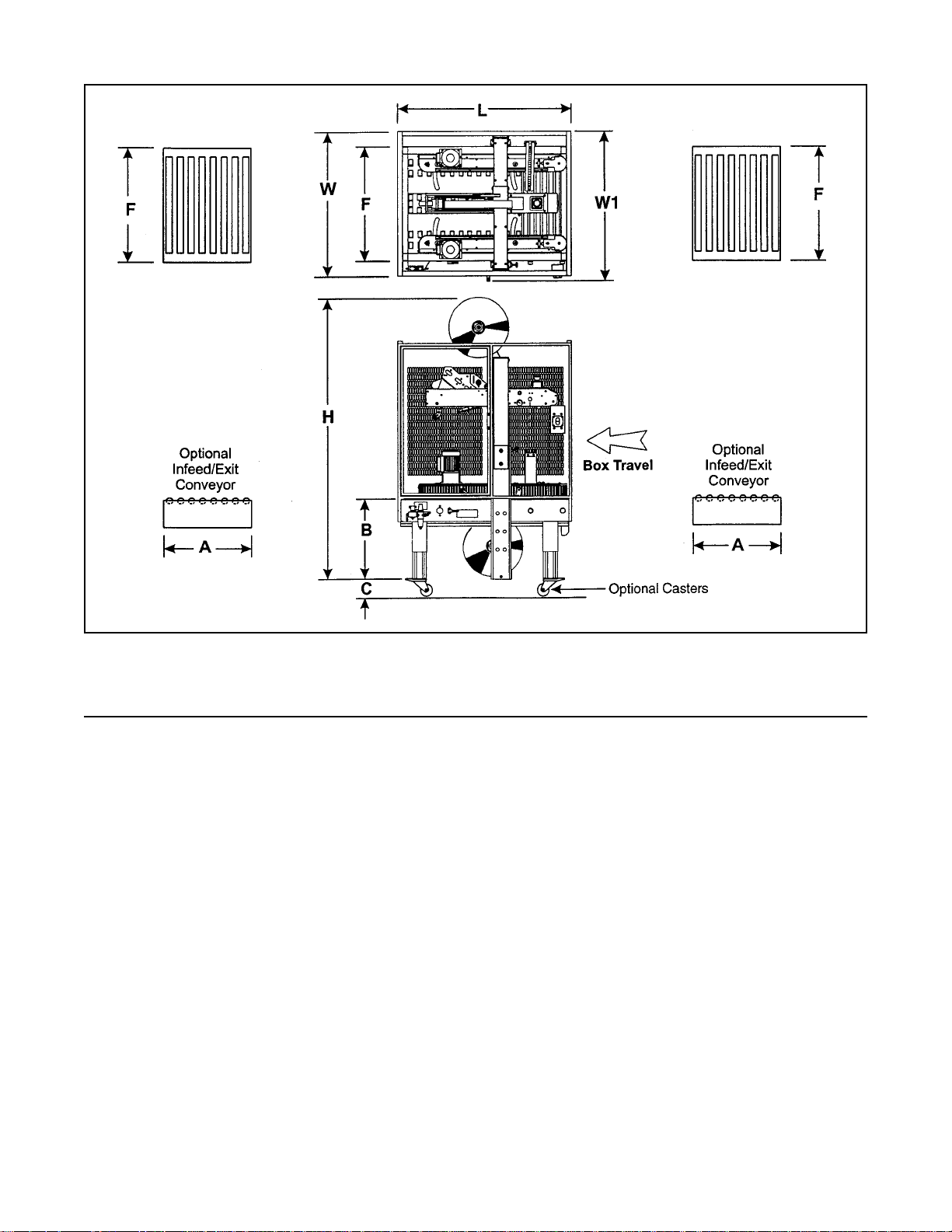
Specifications (Continued)
10. Machine Dimensions:
W W1 L H A* B C** F
Minimum
millimeters 970 1010 1180 1675 460 510 108 770
[Inches] [38.25] [39.75] [46.50] [66.00] [18.00] [20.00] [4.25] [30.38]
Maximum
millimeters 1955 690
[Inches] - - - - - - [77.00]*** - - [27.25] - - - -
* Exit conveyor is optional
** Casters are optional
*** When columns are adjusted to upper position, "H" maximum dimension is 2062 mm [81.19 inches]. (See
"Special Set-Up Procedure – Outer Column Re-Positioning", page 24)
Weight – 225 kg [500 pounds] crated (approximate)
208 kg [460 pounds] uncrated (approximate)
11. Set-Up Recommendations:
• Machine must be level.
• Customer supplied infeed and exit conveyors (if used) should provide straight and level box entry and exit.
• Exit conveyors (powered or gravity) must convey sealed boxes away from machine.
9
Page 15

Installation and Set-Up
Receiving And Handling
After the machine has been uncrated, examine the
case sealer for damage that might have occurred
during transit. If damage is evident, file a damage
claim immediately with the transportation company
and also your 3M Representative.
Machine Set-Up
Important – Read "Warnings" on page 17
before attempting to set-up the case sealer
for operation.
The following instructions are presented in the order
recommended for setting up and installing the case
sealer. Following them step by step will result in an
installation in your production line that best utilizes
the many features built into the case sealer. Refer
to Figures 3-1 and 3-2 to identify the various
components of the case sealer.
Note – A tool kit consisting of metric open end
and hex socket wrenches is provided with the
machine. These tools should be adequate to setup the machine, however, other tools supplied by
the customer will be required for machine maintenance.
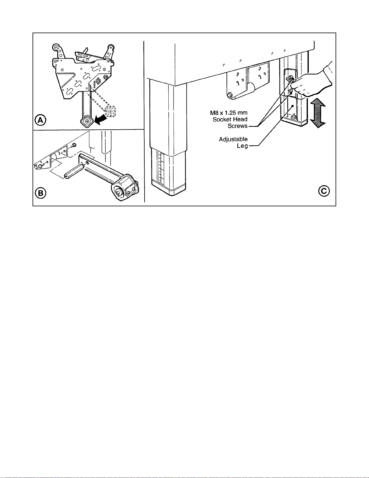
5. Ensure that the tape drum bracket assembly,
located on the lower taping head, is mounted
straight down, as shown in Figure 2-1A. The
tape drum bracket assembly can be pivoted to
provide tape roll clearance in certain cases.
6. Use appropriate material handling equipment to
remove the machine from the pallet and move it
into position.
CAUTION – Machine weighs
approximately 208 kg [460 pounds]
uncrated.
7. Adjust machine bed height. The case sealer is
equipped with four adjustable legs that are
located at the corners of the machine frame.
The legs can be adjusted to obtain different
machine bed heights from 510 mm [20 in]
minimum to 690 mm [27.25 in] maximum.
Note – Minimum machine bed height can be
reduced to 400 mm [15.75 inch] by moving
outer columns up one set of mounting holes.
However, this change also reduces minimum
box height of 127 mm [5.00 inch] to 232 mm
[9.12 inch]. (See "Special Set-Up Procedure
– Outer Column Re-positioning", page 24.)
PACKAGING AND SEPARATE PARTS
1. Lift off fiberboard cover off pallet after removing
staples at bottom.
2. Remove protective wrapping around machine.
3. Remove hardware that secures case sealer legs
to pallet.
4. Cut cable ties that secure upper assembly to
machine bed on each side of machine. Remove
and discard cable ties and foam blocks.
Refer to Figure 2-1C and set the machine bed
height as follows:
a. Use appropriate material handling
equipment and blocking techniques to raise
the machine frame to allow adequate leg
adjustment.
b. Loosen, but do not remove, two M8 x 16
socket head screws in one leg (use M6 hex
wrench). Adjust the leg length for the
desired machine bed height. Retighten the
two screws to secure the leg. Adjust all four
legs equally.
10
Page 16
Installation and Set-Up (Continued)
Figure 2-1 – Conveyor Bed Height Adjustment and Lower Tape Drum Bracket Position
OUTBOARD TAPE ROLL MOUNTING (Lower
Taping Head Alternate Position)
Remove the tape drum bracket assembly,
spacer and fasteners from the lower taping
head. Install and secure on the infeed end of
the lower frame, as shown in Figure 2-1B.
TAPING HEADS
Tape Width – the taping heads have been preset to accommodate 72 mm [3 inch] wide tape
rolls. To apply 48 mm [2 inch] or 42 mm
[1.75 inch] wide tapes, refer to Section II,
"Adjustments – Tape Web Alignment", page 11.
Tape Leg Length – taping heads are pre-set to
apply 70 mm [2.75 in] long tape legs. To
change tape legs to 50 mm [2.0 inch], refer to
Section I, "Special Set-Up Procedure –
Changing Tape Leg Length", page 24.
BOX SIZE CAPACITY OF CASE SEALER
At its factory setting, the case sealer handles
box sizes up to 533 mm [21.00 in] maximum
height. If larger capacity is needed, the
machine can be adjusted to accommodate
boxes up to 644 mm [25.38 in] high. Refer to
page 24, "Special Set-Up Procedures – Outer
Column Re-positioning", for set-up procedure.
Note – Adjusting machine to accommodate 644
mm [25.38 in] high boxes also increases
minimum box size to 232 mm [9.12 in].
11
Page 17
Installation and Set-Up (Continued)
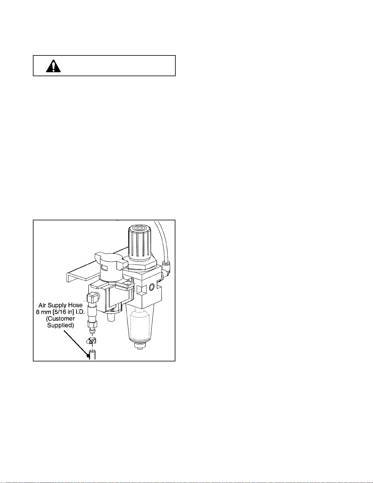
PNEUMATIC CONNECTION
WARNING – Use care when working
with compressed air.
The case sealer requires a 6.5 bar gauge
pressure [95 PSIG], 110 litre/min @ 21° C,
1.01 bar [3.75 SCFM] compressed air supply.
Using customer supplied air hose (8 mm [.31 in]
I.D.) and clamp provided with machine, connect
plant air to barbed fitting on inlet side of
"On/Off" valve. See Figure 2-2.
Note: If
another type of connector is desired, the barbed
fitting can be replaced with the desired 1/4-18
NPT connector.
Note – The air valve has provisions for lock
out/tag out according to plant regulations.
ELECTRICAL CONNECTION AND CONTROLS
The electrical control box, located on the lower
right side of the machine frame, contains the
pre-set circuit breaker. The control box can be
located on the opposite side of the machine
frame if desired. A standard three conductor
power cord with plug is provided at the back of
the electrical control box for 115 Volt, 60 Hz, 6.4
Amp electrical service. The receptacle
providing this service shall be properly
grounded. Before the power cord is plugged
into 115 Volt, 60 Hz outlet make sure the red
"Off" button is depressed and that all packaging
materials and tools are removed from the
machine. Do not plug electrical cord into
outlet until ready to run machine.
Note – Machines outside the U.S. may be
equipped with 220/240 Volt, 50 Hz systems
or other electrical requirements compatible
with local practice.
Figure 2-2 – Pneumatic Connection
INITIAL START-UP OF CASE SEALER
After completing the "Installation and Set-Up"
procedure, continue through "Operation" for
tape loading and start-up to be sure case sealer
is properly adjusted to run boxes.
12
Page 18
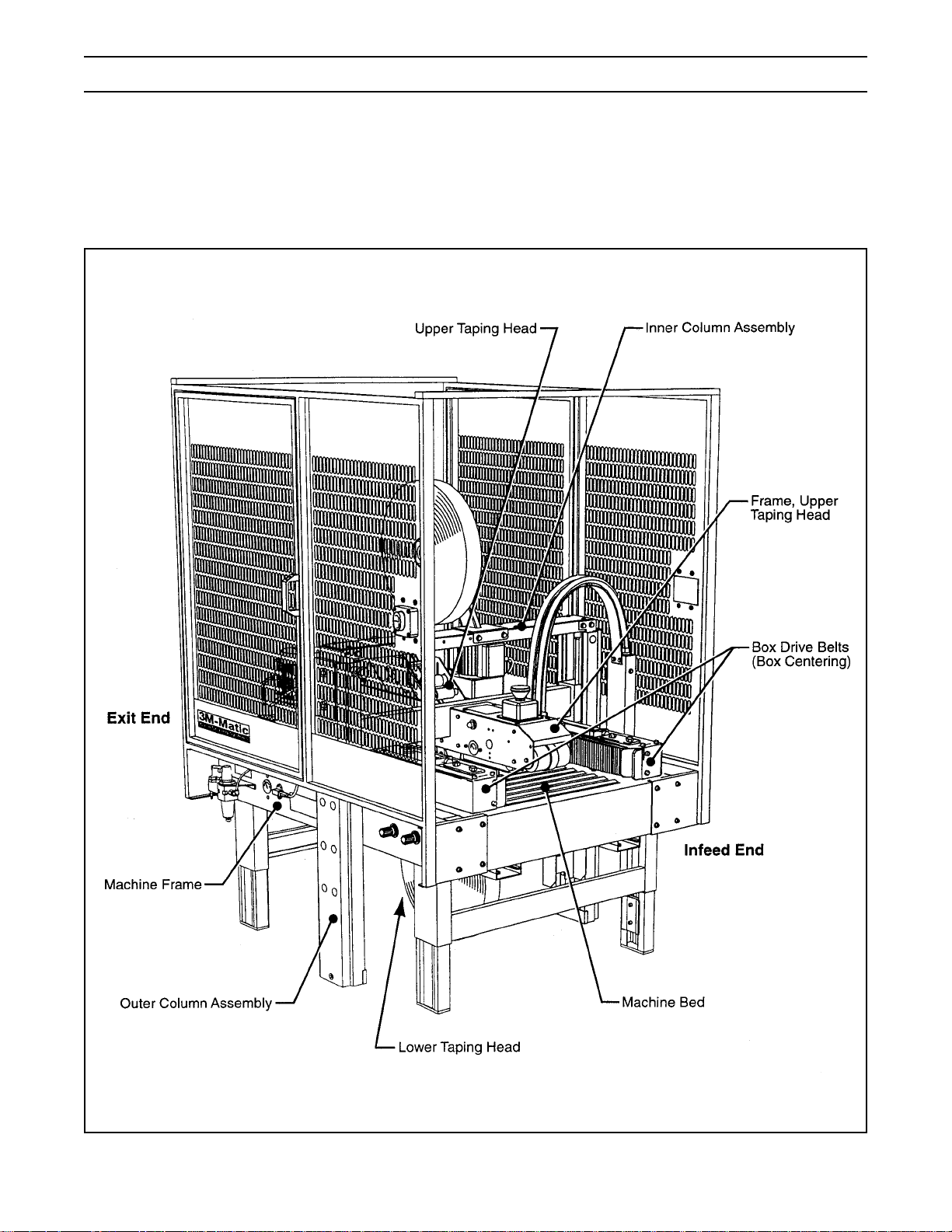
Operation
IMPORTANT – Before operating the case sealer, read the "Important Safeguards", pages 3-6 and
"Warnings" on page 17 as well as all of the "Operation" instructions.
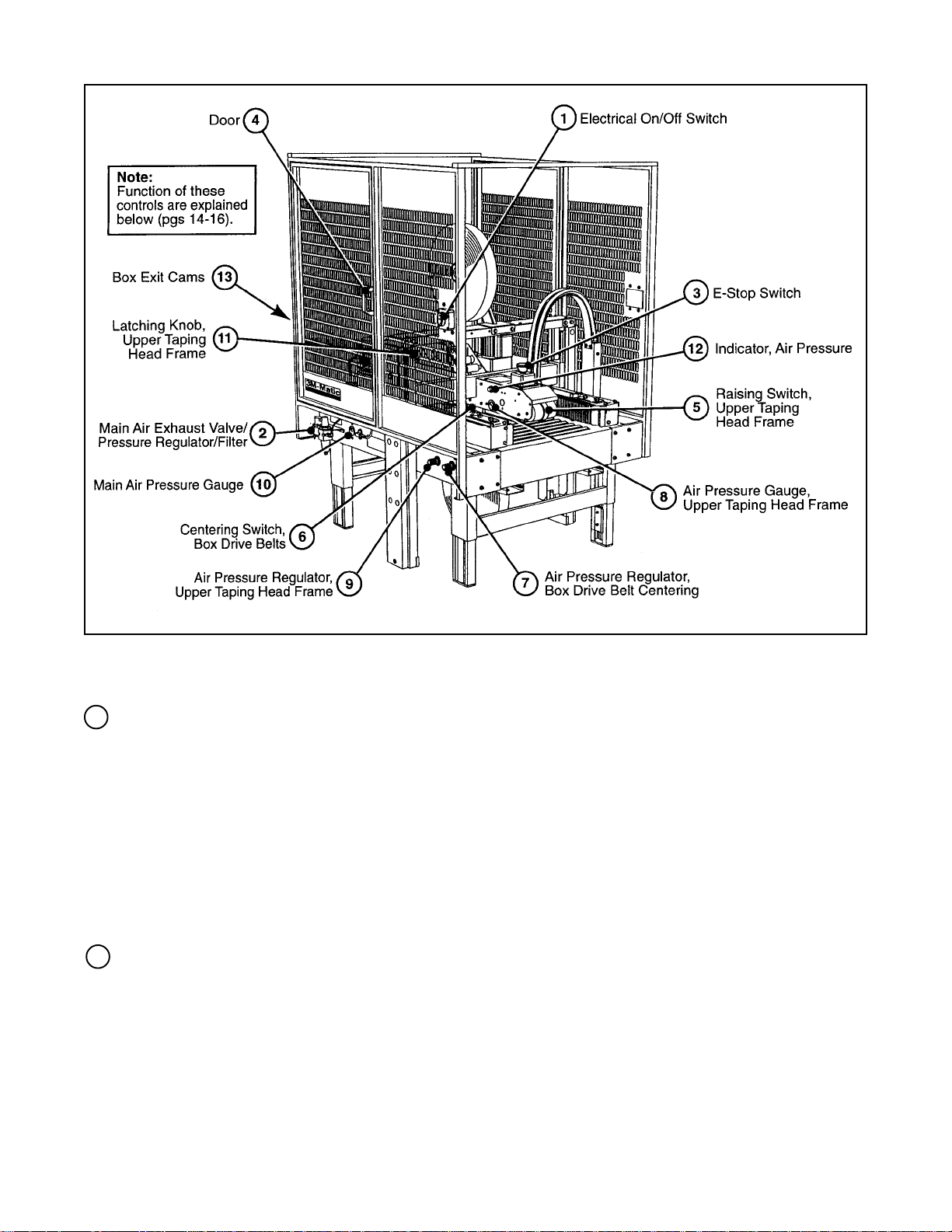
Refer to Figure 3-1 and 3-2 to acquaint yourself with the various components and controls of the case sealer.
Also see Figures 3-1 and 3-2 in Section II for taping head components.
Figure 3-1 – Case Sealer Components
13
Page 19
Operation (Continued)
Figure 3-2 – Controls, Valves and Switches
1 Electrical "On/Off" Switch
The box drive belts are turned on and off ("Off
button is red) with the electrical switch on the
left side guard on the infeed end of the
machine.
Note – The case sealer has a circuit breaker
located in the electrical control box on the
lower right side of the machine frame. If
circuit becomes overloaded and circuit
breaker trips, see "Maintenance – Circuit
Breaker", page 22.
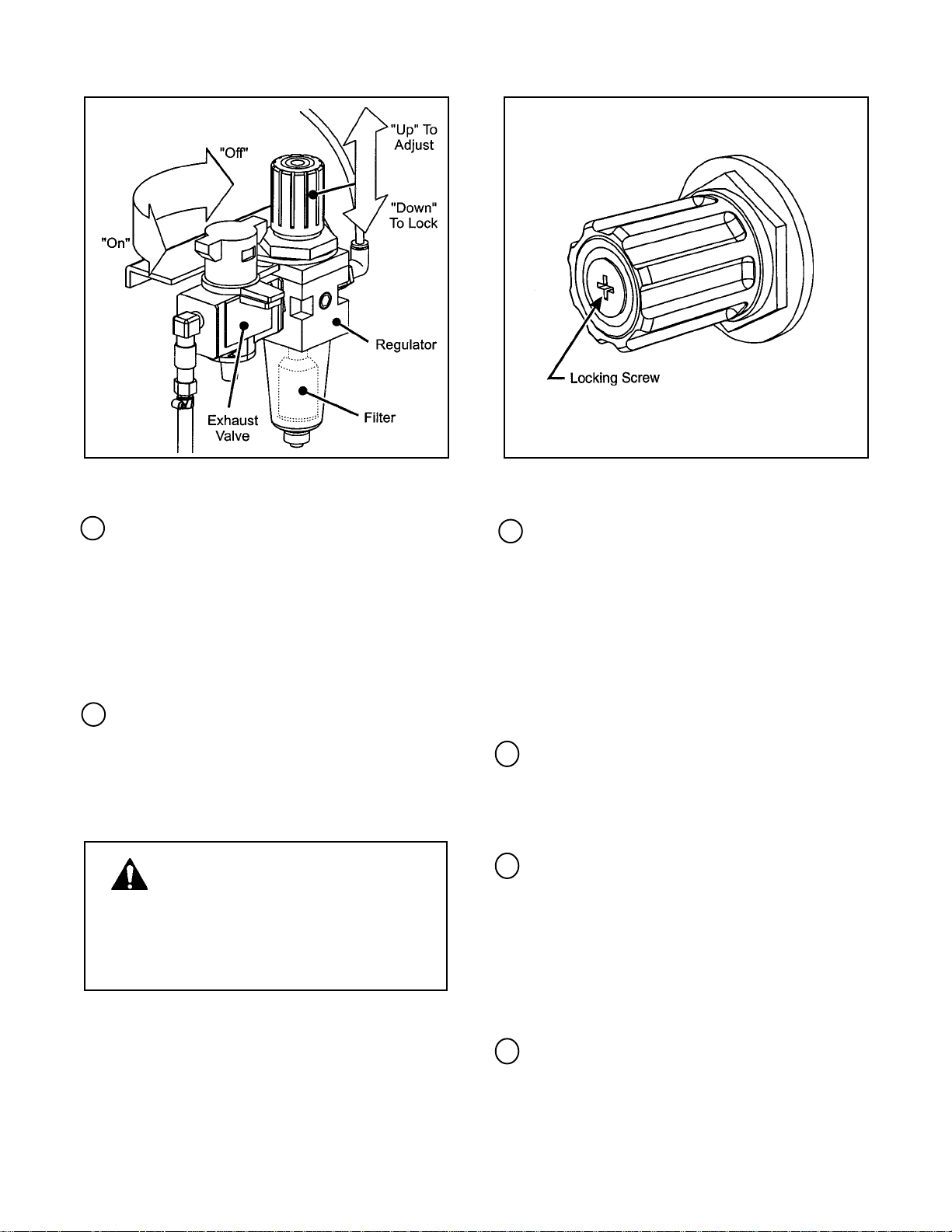
2 Main Air "On/Off" Valve/Pressure Regulator/
Filter
– Figure 3-3
This set of pneumatic components controls,
regulates and filters plant air supply to the two
separate control circuits of the case sealer.
"On/Off" Valve – "On" turn to "SUP" – "Off"
turn to "EXH".
Note – Turning air supply "Off"
automatically bleeds air pressure from the
case sealer air circuits.
Always turn the air "Off" when machine is not
in use, when servicing the machine, or when
connecting or disconnecting air supply line.
Note – The air valve has provisions for lockout/
tagout according to plant regulations.
Pressure Regulator regulates main air
pressure to the machine. The factory set
point if 95 PSIG. To re-adjust pressure, pull
knob up and turn to desired pressure. Push
down to lock setting.
Filter removes dirt and moisture from plant
air before it enters the case sealer pneumatic
circuits. If water collects in bottom of bowl,
lift up on the valve on the bottom of bowl to
drain.
14
Page 20
Operation (Continued)
Figure 3-3 – "On/Off" Valve/Regulator/Filter
3 E-Stop Switch
The E-Stop switch kills electrical power and
exhaust air pressure from the drive belt
assemblies. The upper head assembly will
raise to its upper most position. To restart
machine, rotate E-stop switch (releases switch
latch) and then restart machine by pressing
electrical switch "I" (On) button on side guard
of machine.
4 Door
The door is equipped with a safety interlock
which kills electrical power and exhaust air
pressure from the drive belt assemblies. The
upper head assembly will raise to its upper
most position when the door is opened.
WARNING – The E-Stop switch or
door must not be used for raising
the upper head assembly for maintenance
work. If these are used the upper head
assembly could lower during maintenance
work causing injury to personnel.
Figure 3-4 – Air Regulator, Drive Belts
5 Raising Switch, Upper Taping Head Frame
This switch, when touched by the leading
edge of a box, pneumatically raises the upper
frame to allow insertion of a box under the
upper frame, as the box moves under the
switch, releasing it, the upper frame descends
on the box and the drive belts convey the box
through the machine. When switch is
actuated by hand, the upper frame rises to its
maximum height. Released, the upper frame
descends to its rest position.
6 Centering Switch, Box Drive Belts
This pneumatic switch controls the closing
(centering) of the drive belts. When switch is
activated by a box passing under it, the drive
belts close and center the box.
7 Air Pressure Regulator, Box Drive Belt
Centering – Figure 3-4.
This regulator is used to adjust drive belt
centering pressure. The factory set point is 5
turns clockwise. If more pressure is needed to
center box, turn knob clockwise to desired
pressure. If box is being crushed, turn knob
counterclockwise to relieve pressure.
Regulator is locked by tightening screw.
8 Air Pressure Gauge, Upper Taping Head
Frame
This gauge, used in conjunction with the upper
frame air regulator, provides operator with a
reference pressure setting for various size/
weight boxes.
15
Page 21
Operation (Continued)
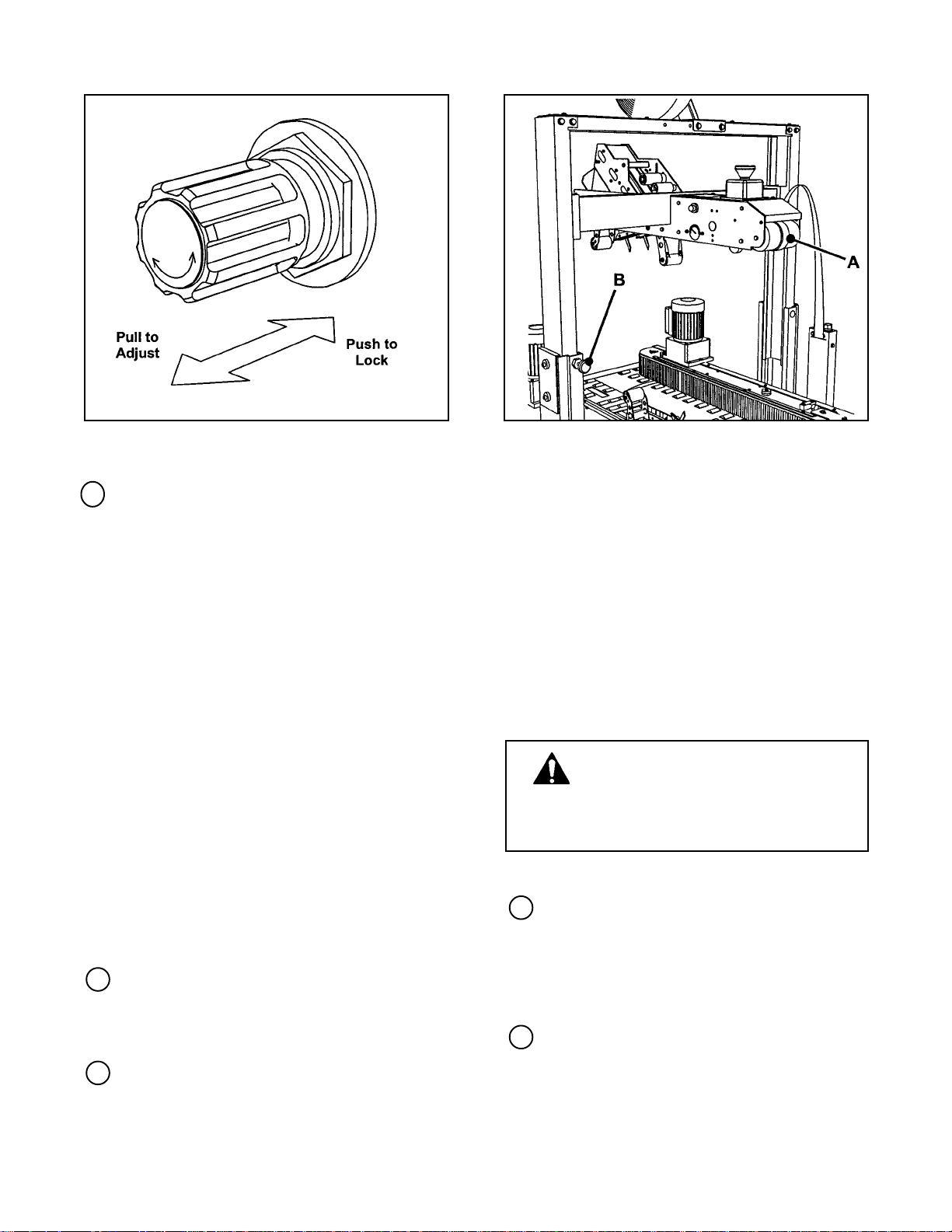
Figure 3-5 – Air Regulator, Upper Taping Head
Frame
9 Air Pressure Regulator, Upper Taping
Head Frame – Figure 3-5
Set nominally to control "down" pressure
against box. The factory set point is 15 PSIG
[1 bar]. The regulator setting is adjusted as
necessary to allow free movement of boxes
through taping heads while maintaining boxes
flaps in fully closed position. Decreasing air
pressure will increase down pressure on
boxes while increasing air pressure will
decrease down force on boxes.
For boxes which are fully packed with
products that support the top flaps, the
adjustment of this regulator is not critical since
the boxes can support the pressure of the
upper frame at a wide range of regulator
settings. However, if under-filled or fragile
boxes are sealed, this regulator is used to set
the upper frame at the minimum setting while
still maintaining adequate closure of boxes.
Figure 3-6 – Latching Knob, Upper Taping Head
Frame
To raise and latch the upper frame:
1. Push and hold the upper frame raising
switch "A".
2. Push and hold latching knob "B".
3. Release switch "A".
4. Release knob "B".
5. Shut off air supply.
To release and lower the upper frame:
1. Turn on air supply.
2. Push and release switch "A".
WARNING – Do not put hands
beneath upper taping head frame
when upper frame lowers to its rest
position. Severe personal injury could
result.
The air regulator is adjusted by pulling out to
adjust and pushing in to lock the setting as
shown in Figure 3-5.
10 Main Air Pressure Gauge
Indicates main air regulator pressure setting.
Air regulator should be adjusted so gauge
reads 6.5 bar gauge pressure [95 PSIG].
11 Latching Knob, Upper Taping Head Frame
–Figure 3-6
The mechanical latch is provided to hold the
upper frame at the fully raised position for
tape threading and maintenance.
12 Indicator, Air Pressure
An "Optical" Warning Indicator for the
compressed air circuit of the machine is
located on the upper taping head frame just
behind the red "Stop" button. When indicator
is "Red", air circuit is on.
13 Box Exit Cams
These cams, when tripped by exiting box,
signal drive belts to return to their fully open
(rest) position.
16
Page 22

Operation (Continued)
WARNINGS
1. Turn electrical and air supply off and disconnect before servicing taping heads or
performing any adjustments or maintenance on the machine.
2. Turn electrical and air supply off when machine is not in use.
3. Before turning drive belts on, be sure no tools or other objects are on the conveyor bed.
4. Keep hands and loose clothing away from moving belts.
5. Never attempt to remove jammed boxes from the machine while machine is running.
6. Be aware of the pneumatically controlled movement of the upper frame and drive belts.
Keep away from these components when air and electrical supplies are on.
7. When feeding boxes to the machine by hand, push box in from end only – DO NOT PUSH
WITH HANDS ON ANY CORNER OF THE BOX.
8. Both the upper and lower taping heads utilize extremely sharp knife blades. The blades are
located under the orange blade guard which has the "WARNING – SHARP KNIFE" label.
Before loading tape, refer to Figures 3-1 and 3-2 in Section II to identify the blade location.
Keep hands out of these areas except as necessary to service the taping heads.
9. Failure to comply with these warnings can result in severe personal injury and/or equipment
damage.
Tape Loading/Threading
See Section II, pages 7 and 8.
Note – If lower tape drum is mounted in lower
outboard position remove taping head from
machine bed by pulling straight up, insert
threading needle in taping head and replace
taping head. Install tape roll on drum (adhesive
on tape leg up), thread tape leg under knurled
roller on outboard mount, then attach tape leg to
threading needle and pull tape through taping
head with threading needle.
17
Page 23

Operation (Continued)
Box Sealing
1. Turn main air valve "On".
2. Push electrical switch "On" to start drive belts.
3.
With access door closed, feed boxes to machine
at minimum 460 mm [18 in] intervals.
WARNING – Keep hands away from
drive belts when feeding boxes to
machine. Push boxes from the end only,
DO NOT push with hands on any corners
of the box.
Operator pushes box against raising switch on
upper frame assembly, as shown in Figure 3-7,
causing the upper frame (taping head) to be
raised above the box.
4. Box is then pushed under belt centering roller
switch (Figure 3-8), which closes drive belts and
conveys box through machine.
Figure 3-7 – Operation
Once the box is conveyed from under the upper
taping head, the upper frame assembly returns
to its rest position, ready for insertion of next
box. Also, box exiting machine, trips box exit
cams which signal drive belts to return to their
full open (rest) position.
5. Turn air and electrical supplies "Off" when
machine is not in use.
6. Reload and thread tape as necessary.
7. Be sure machine is cleaned and lubricated
according to recommendations in
"Maintenance" section of this manual.
Notes
1. Machine or taping head adjustments are
described in "Adjustments", Section I for
machine or Section II for taping heads.
2. Box drive motors are designed to run at a
moderate temperature of 40°C [104°F].
In some cases, they may feel hot to the
touch.
Figure 3-8 – Operation 8888 – Operation
Box Jam
If a box should jam or there is a need to shut the
machine off with the upper head assembly in the up
position, the E-Stop button can be pressed or the
guard door can be opened. Either function will
automatically raise the upper head assembly to its
highest position and the air pressure will be
exhausted from the belt assemblies. The box can
be removed and the tape should be checked to
insure that it is threaded properly. When the E-Stop
is pulled up or the door closed the upper head
assembly will lower to the lowest position.
18
Page 24

Maintenance
The case sealer been designed for long, trouble
free service. The machine will perform best when it
receives routine maintenance and cleaning.
Machine components that fail or wear excessively
should be promptly repaired or replaced to prevent
damage to other portions of the machine or to the
product.
WARNING – Turn off electrical and
air supplies and disconnect power
cord from electrical supply before
beginning maintenance. If electrical
power is not disconnected, severe injury
to personnel could result.
Cleaning
Note – Never attempt to remove dirt from taping
heads by blowing it out with compressed air. This
can cause the dirt to
be blown inside the motor and onto sliding
surfaces which may cause premature equipment
wear. Never wash down or subject equipment to
conditions causing moisture condensation on
components. Serious equipment damage could
result.
Figures 4-1 illustrates the frame points which should
be lubricated every 250 hours of operation.
Lubricate the points noted by solid arrow ( ) with
SAE #30 non-detergent oil. Lubricate the points
noted by outline arrow ( ) with multipurpose
grease.
Note – Wipe off excess oil and grease. It will
attract dust and dirt which can cause premature
equipment wear and jamming. Take care that
oil and grease are not left on the surface of
rollers around which tape is threaded, as it can
contaminate the tape's adhesive.
Taping Head Lubrication – See Section II,
"Maintenance – Lubrication", page 10.
Regular slotted containers produce a great deal of
dust and paper chips when processed or handled in
equipment. If this dust is allowed to build-up on
machine components, it can cause component wear
and overheating of drive motor. The dust build-up
can best be removed from the machine by a shop
vacuum. Depending on the number and type of
boxes sealed in the case sealer, this cleaning
should be done approximately once per month. If
the boxes sealed are dirty, or if the environment in
which the machine operates is dusty, cleaning on a
more frequent basis may be necessary. Excessive
dirt build-up that cannot be removed by vacuuming
should be wiped off with a damp cloth.
Lubrication
Like most other equipment, the case sealer must be
properly lubricated to insure long, trouble free
service. Most of the machine bearings are
permanently lubricated and sealed and do not need
to be greased. The drive motor is also permanently
lubricated and does not require additional
lubrication.
Figure 4-1 – Frame Lubrication Points
19
Page 25

Maintenance (Continued)
WARNING – Turn off electrical and air supplies and disconnect power cord from electrical
supply before beginning maintenance. If power cord is not disconnected, severe injury to
personnel could result.
Drive Belts
WARNING –The E-Stop switch or
door must not be used for raising
the upper head assembly for maintenance
work. If these are used the upper head
assembly could lower during maintenance
work causing injury to personnel.
Note – 3M recommends the replacement of
drive belts in pairs, especially if belts are
unevenly worn.
REPLACEMENT – SEE STEPS 1 THRU 17
TENSION ADJUSTMENT – SEE STEPS
11, 14 and 15
1. Turn air and electrical supply on.
2. Push and hold the upper frame raising switch
(A). Figure 3-2, page 16.
1-8, 10,
3. Push and hold the latching knob (B). Figure 3-6.
page 16.
4. Release switch (A). Knob (B) will lock the upper
head assembly in the upper position.
5. Shut off air supply.
6. Disconnect motor plug (A). Figure 4-2.
7. Remove and retain snap rings (B) and special
washer (C) from front and rear arm assembly
pivots. Figure 4-2.
8. Lift side drive assembly (D) up and off arm
assembly pivots. Figure 4-2.
WARNING – Each drive assembly
weighs approximately 20.4 kg
[45 lbs]. To prevent injury, drive
assembly should be lifted by two people,
one at the front and one at the rear.
9. Remove and retain the four screws (E),
washers (F) and side cover (G). See Figure 4-2.
Figure 4-2 – Box Drive Belt (Left Side View – Infeed End)
20
Page 26
Maintenance (Continued)
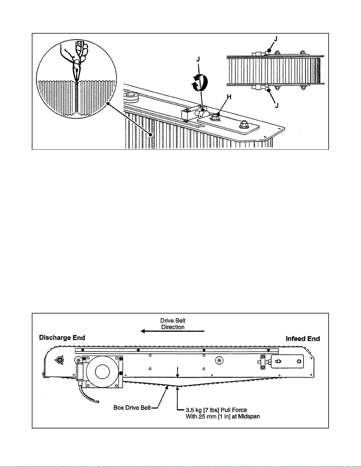
Figure 4-3 – Box Drive Assembly, Infeed End
10. Loosen, but do not remove lock nuts (H) on
both the upper and lower belt tension
assemblies. See Figure 4-3.
11. Turn belt adjustment screws (J) clockwise on
both the upper and lower tension assemblies
until belt is loose. See Figure 4-3.
12. Locate the belt lacing (joint) by turning the belt
manually. Remove the pin with pliers. Remove
and discard old belt.
13. Install the new belt around drive rollers and
insert new pin. Pin must not extend beyond
edge of belt.
Note – Before installing new drive belt,
check the belt inside surface for drive
direction arrows and install belt accordingly.
If no arrows are shown, the belt may be
installed either way.
14. To set drive belt tension, turn adjustment
screws (J) equally on both the upper and lower
tension assemblies. Turn the screws
counterclockwise to increase tension or
clockwise to decrease tension. See Figure 4-3.
Use a force gauge to pull the belt outward
25 mm [1 in] at midspan, as shown in
Figure 4-4 with a moderate pulling force of
3.5 kg [7 lbs].
15. After adjusting belt tension, tighten lock nuts (H)
on both the upper and lower tension assemblies.
16. Reverse procedures in Steps 1-6 to complete
drive reassembly.
17. Repeat procedure for other belt.
Figure 4-4 – Box Drive Belt Tension Adjustment, Top View
21
Page 27

Maintenance (Continued)
WARNING – Turn off electrical and air supplies and disconnect power cord from electrical
supply before beginning maintenance. If power cord is not disconnected, severe injury to
personnel could result.
Circuit Breaker
The case sealer is equipped with a circuit breaker
which trips if the motors are overloaded. Located
inside the electrical enclosure on the side of the
machine frame just below the machine bed, the
circuit breaker has been pre-set at 1.9 amps and
requires no further maintenance.
WARNING – The following
procedure must be performed by
trained service personnel because of the
high voltage electrical hazard within the
control box.
If circuit is overloaded and circuit breaker trips,
unplug machine from electrical power:
1. Determine cause of overload and correct.
2. Remove electrical enclosure cover.
3. Press the red "Reset" button and then the
green "Start" button.
4. Replace cover.
5. Plug in machine.
6. Press machine "On" button to resume case
sealing.
Knife Replacement, Taping Head
See Section II, "Maintenance – Knife
Replacement", page 9.
22
Page 28

Adjustments
WARNING – Turn air supply and electrical power off and disconnect power cord from power
supply before beginning adjustments. If power cord is not disconnected, severe injury to
personnel could result.
Drive Belt Tension
Tension adjustment of the drive belts may be required during normal operation. Belt tension must be adequate to
positively move the box through the machine and they should run fully on the surface of the pulleys at each end of
the frame. The idler pulleys on the infeed end are adjusted in or out to provide proper belt tension. Each belt is
adjusted separately.
Belt tension is obtained by tightening the adjustment screws so that a moderate pulling force of 3.5 kg [7 lbs]
applied at the midspan, as shown in Figure 4-4, will deflect the belt 25 mm [1 in]. This will assure positive contact
between the belt and the drive pulley on the discharge end of the taping head.
To adjust belts, see "Maintenance – Drive Belts", page 20.
Taping Head Adjustments – Refer to Section II
WARNING – Use care when working near tape cut-off blades on taping heads as blades are
extremely sharp. If care if not taken, severe injury to personnel could result.
TAPE WEB ALIGNMENT – Section II, Page 11
TAPE DRUM FRICTION BRAKE – Section II, Page 11
APPLYING MECHANISM SPRING – Section II, Page 11
ONE-WAY TENSION ROLLER – Section II, Page 12
TAPE LEG LENGTH ADJUSTMENT – Section II, Page 13
23
Page 29
Special Set-Up Procedure
WARNING – Turn air supply and
electrical power off and disconnect
power cord from power supply before
beginning special set-up procedure. If
power cord is not disconnected, severe
injury to personnel could result.
Changing the Tape Leg Length
(From 70 to 50 mm [2.75 to 2.00 in])
Changing tape leg length to 50 mm [2 in] allows
taping of smaller boxes. Refer to "Specifications –
Box Weight and Size Capacities", page 8 for box
sizes.
CASE SEALER FRAME
No changes required.
TAPING HEADS
WARNING – Use care when working
near taping head knives as knives
are extremely sharp. If care is not taken,
severe injury to personnel could result.
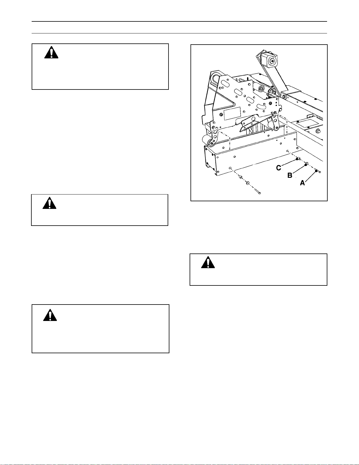
1. Remove upper taping head. Loosen and
remove four (each) M6 x 25 flat head screws
(A), special washers (B) and spacers (C) that
fasten head to upper assembly as shown in
Figure 5-1. Support or hold taping head to
keep it from falling when screws are
removed.
2. Turn air supply on and raise and latch upper
assembly in full up position. Turn air supply off.
WARNING –The E-Stop switch or
door must not be used for raising
the upper head assembly for maintenance
work. If these are used the upper head
assembly could lower during maintenance
work causing injury to personnel.
3. Remove lower taping head by pulling straight
up.
4. Refer to Section II "Adjustments – Changing
Tape Leg Length", page 13.
Figure 5-1 – Upper Taping Head Mounting
Outer Column – Re-Positioning
WARNING – It is recommended that
no less than two people assist on
this set-up or severe injury or equipment
damage could result.
Moving the outer columns to the upper set of
mounting holes, increases the maximum box size
(height) handled by the case sealer from 533 mm
[21.00 in] to 644 mm [25.38 in]. (Dimensions given
are with lift cylinders mounted in standard position.)
Note – This also increases the minimum box
height from 127 mm [5.00 in] to 232 mm [9.12 in].
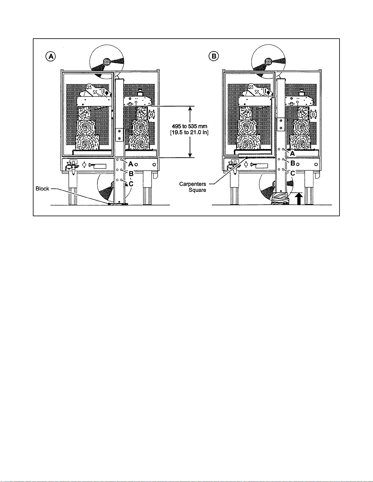
Refer to Figure 5-2
1. With air on, raise and latch upper assembly in
full raised position. Be sure electrical supply
is disconnected.
2. Place solid blocks 495 to 535 mm [19.5 to
21.0 in] high under front and back of upper
assembly as shown in Figure 5-2A.
24
Page 30
Special Set-Up Procedure (Continued)
Figure 5-2 – Column Re-Positioning
3. Actuate raising switch to release upper
assembly latch. (Upper assembly will rest on
blocks.) Turn off and disconnect air supply.
4. Remove plastic plugs and M8 x 20 socket head
capscrews from (A) and (B) in one side column
(4 each). Slide side column up approximately
110 mm [4.25 in] and re-install capscrews in (B)
and (C). DO NOT TIGHTEN SCREWS. Repeat
procedure for other side column.
5. Using carpenters square, line up column
perpendicular to machine bed as shown in
Figure 5-2B. Tighten capscrews and install
plastic plugs. Repeat this procedure for both
columns.
6. Connect and turn on air supply, actuate raising
switch and latch upper assembly in full up
position.
7. Remove blocking, unlatch and lower upper
assembly.
25
Page 31

THIS PAGE IS BLANK
26
Page 32

Troubleshooting
The Troubleshooting Guide lists some possible machine problems, causes and corrections. Also see Section II
"Troubleshooting", pages 15 and 16 for taping head problems.
Troubleshooting Guide
Problem
Drive belts do not convey boxes
Drive belts do not turn
Cause
Narrow boxes
Worn drive belts
Top taping head does not apply
enough pressure
Taping head applying spring
holder missing
Taping head applying spring set
too high
Worn or missing friction rings
Drive belt tension too low
Electrical disconnect
Correction
Check machine specifications.
Boxes are narrower than
recommended, causing slippage
and premature belt wear.
Replace drive belts
Adjust the upper drive assembly
force adjust regulator to increase
the force against the top of the
box. Turn air regulator
counterclockwise.
Replace spring holder
Reduce spring pressure
Replace friction rings
Adjust belt tension
Check power and electrical plug
Drive belts break
Squeaking noise as boxes pass
through machine
Tape not centered on box seam
Circuit breaker not at correct
setting
Motor not turning
Worn belt
Dry compression rollers
Dry column bearings
Defective column bearings
Tape drum not centered
Drive belts not centered
Box flaps not of equal length
Set to correct current value
Evaluate problem and correct
Replace belt
Lubricate compression rollers
Lubricate column bearings
Replace column bearings
Reposition tape drum
Adjust centering guides
Check box specifications
(Continued)
27
Page 33

Troubleshooting (Continued)
Troubleshooting Guide
Problem
Cause
Correction
Upper drive assembly does not
move up or moves up slowly
Upper taping head does not move
down at the end of the taping
cycle
Lower air pressure
Defective head raising valve
Worn head raising valve actuator
Clogged or damaged exhaust
mufflers on the upper ends of the
head raising cylinders
Defective head power valve
Upper drive assembly force
adjust regulator set too light
Defective top drive assembly
force adjust regulator
Disconnect the air supply. Make
sure main pressure regulator reads
zero. Reconnect air supply and
adjust regulator to read 5 bar
[70 PSIG].
Clean or replace head raising
valve
Replace valve
Clean or replace exhaust mufflers
Clean or replace the head power
valve
Adjust the upper drive assembly
force adjust regulator to increase
the force against the top of the
box. Turn air regulator
counterclockwise.
Replace regulator
Upper head assembly comes
down too fast or too hard
Centering drive assemblies
move slower than normal
Defective "OR" valve
Defective head power valve
Upper drive assembly force
adjust regulator set too heavy
Defective upper drive assembly
force adjust regulator
Cushion screw misadjusted
Cushion screw missing
Centering force adjust regulator
set too low
Centering guide cylinder speed
controls not in correct adjustment
Defective centering guide power
valve
Clean or replace valve
Clean or replace valve
Adjust upper drive assembly force
adjust regulator to decrease force
against top of box. Turn regulator
clockwise.
Replace regulator
Adjust cushion screw at base of
cylinder
Replace screw
Adjust regulator
Adjust speed controls mounted on
centering guide cylinder
Clean or replace valve
28
Page 34

800r3 Case Sealer Operating Sequence
29
Page 35

Electrical/Pneumatic Diagrams
WARNING – Electrical service
procedures must be performed by
a qualified electrical technician. Turn
off and disconnect electrical and
pneumatics before servicing unit. High
voltage inside electrical enclosure can
cause severe injury or death.
Figure 6-1 – Electrical Diagram
30
Page 36

31
Page 37

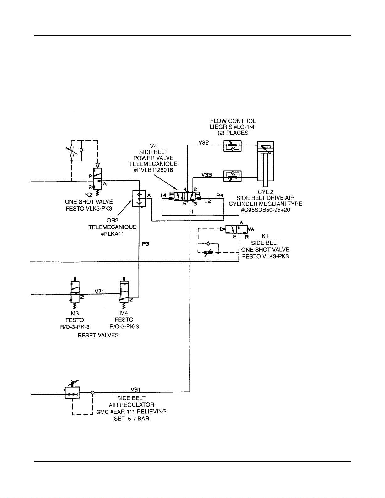
Electrical/Pneumatic Diagrams (Continued)
WARNING – Turn off and disconnect
air and electrical supplies before
servicing pneumatic components. High
pressure air can cause severe injury.
Figure 6-2 – Pneumatic Diagram
32
Page 38
33
Page 39

THIS PAGE IS BLANK
34
Page 40

Parts and Service Information
Spare Parts
The following parts periodically require replacement due to normal wear. They should be ordered immediately
and kept on hand to keep the case sealer in production.
Qty. Section/Ref. No. Part Number Description
1 II/2949-15 78-8057-6181-0 Roller – Applying
1 II/2950-5, 2955-5 78-8057-6180-2 Roller – Buffing
1 II/2950-10 78-8070-1274-1 * Spring – Upper Extension (Silver)
1 II/2952-2 78-8028-7899-7 * Knife – 89 mm/3.5 Inch
1 II/2952-18 78-8113-7030-9 Spring – Torsion
2 II/2952-12 78-8052-6602-6 * Spring – Cutter
1 II/2955-10 78-8070-1273-3 * Spring – Lower Extension (Black)
4 I/7006-42 78-8094-6447-8 Belt – Drive
* Note – These spare parts are supplied with the tool kit that comes with your machine and should also be
ordered separately as used, to keep the case sealer in production.
Labels
In the event that any labels are damaged or destroyed, they must be replaced to ensure operator safety. For
safety and information replacement labels, see Parts Illustration/Lists, Section I, pages 66-67.
Tool Kit
A tool kit, P/N 78-8098-8868-4, packaged separately and included with your machine, contains the necessary
wrenches for use with the metric fasteners on the case sealer. The threading tool, part number 78-8076-4726-4,
contained in the kit is available as a stock replacement item and can be ordered separately.
Parts Ordering/Service
Refer to the first page of this instruction manual for parts ordering or service information.
35
Page 41

Options/Accessories
For additional information on the options/accessories listed below, contact your 3M Representative.
Part Number Option/Accessory
78-8095-4862-7 Infeed/Exit Conveyor Attachment
78-8095-4852-8 3 Inch Tape Edge Fold Attachment (Upper Head)
78-8095-4853-6 3 Inch Tape Edge Fold Attachment (Lower Head)
78-8079-5560-0 Tape Application Sensor Kit
78-8069-3983-7 Caster Kit
36
Page 42

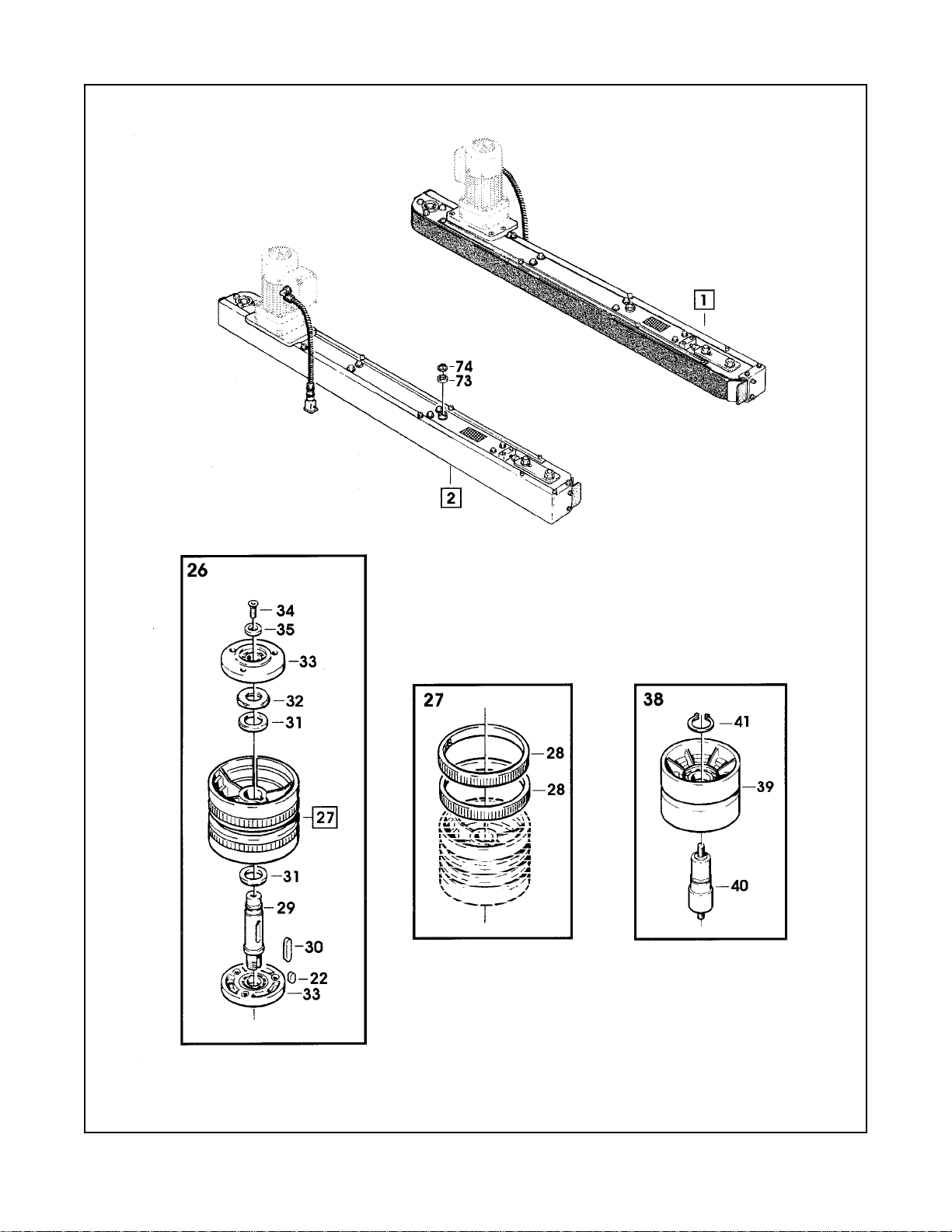
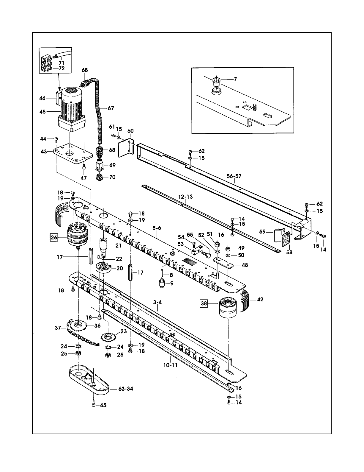
Replacement Parts – Illustrations and Parts Lists
800r3 Random Case Sealer, Type 29600
With AccuGlide™ II STD 3 Inch Taping Heads
1. Refer to first illustration, Frame Assemblies, for the figure number that identifies a specific portion of the
machine.
2. Refer to the figure or figures to determine the individual parts required and the parts reference number.
3. The replacement parts list, that follows each illustration, includes the part number and part description
for the parts in that illustration.
Note – The complete description has been included for standard fasteners and some commercially
available components. This has been done to allow obtaining these standard parts locally,
should the customer elect to do so.
4. Order parts by part number, part description and quantity required. Also include machine name, number
and type.
5. Refer to first page of this instruction manual for parts ordering address and/or phone/fax number.
IMPORTANT – Not all the parts listed are normally stocked items. Some parts or assemblies
shown are available only on a special order basis. Contact 3M/Tape Dispenser Parts to confirm
item availability.
37
Page 43

THIS PAGE IS BLANK
38
Page 44

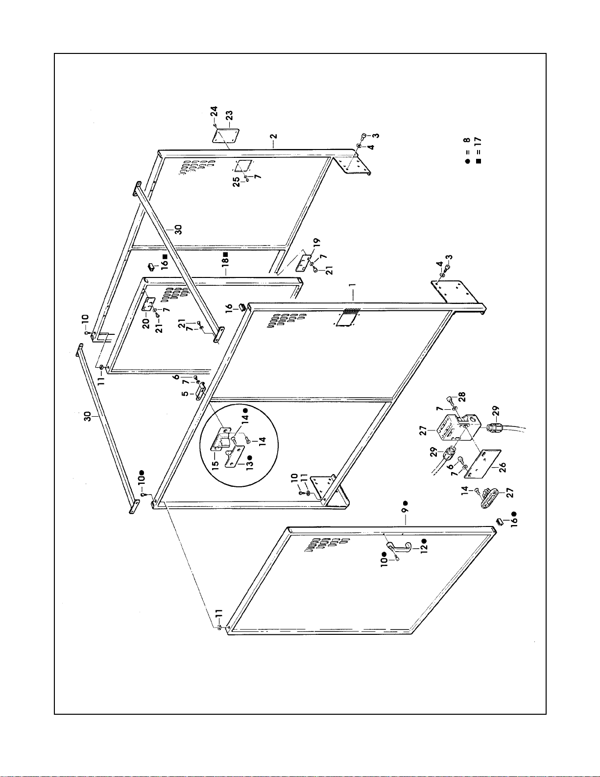
800r3 Random Case Sealer
Frame Assemblies
39
Page 45

800r3 Random Case Sealer
Figure 4896
40
Page 46

Figure 4896
Ref. No. 3M Part No. Description
4896-1 78-8091-0600-4 Housing – Wire
4896-2 26-1003-7963-0 Screw – Soc Hd, M8 x 16
4896-3 78-8094-6489-0 Snap Bushing – SB 1250-15
4896-4 78-8076-4636-5 Strap – Wire
4896-5 78-8010-7163-6 Screw – Hex Hd, M5 x 10
4896-6 78-8005-5741-1 Washer – Plain, M5
4896-7 78-8010-7417-6 Nut – Hex, M5
4896-8 78-8076-4873-4 Plate – Strap
4896-9 78-8076-4638-1 Union PG13.5 – Sleeve / 14
4896-10 78-8094-6445-2 Sleeve – /14, 980 MM
4896-11 78-8060-8029-3 Clamp – 140 x 3,5
4896-12 78-8076-5118-3 Cover – Channel
4896-13 26-1003-5810-5 Screw – Hex Hd, M4 x 8
4896-14 78-8017-9018-5 Washer – Plain, M4 SPEC.
4896-15 78-8060-7785-1 Fairlead – /22
41
Page 47
800r3 Random Case Sealer
Figure 4900
42
Page 48

Figure 4900
Ref. No. 3M Part No. Description
4900-1 78-8113-6835-2 Guard Assembly – L/H, W/English Language Label
4900-2 78-8094-6460-1 Guard – R/H
4900-3 26-1003-7964-8 Screw – Soc Hd, Hex Hd, Soc Dr, M8 x 20
4900-4 78-8017-9318-9 Washer – Plain, 8 MM
4900-5 78-8094-6461-9 Bracket
4900-6 78-8032-0382-3 Screw – Soc Hex Hd, M5 x 16
4900-7 78-8005-5741-1 Washer – Plain, M5
4900-8 78-8094-6462-7 Door Assembly – L/H
4900-9 78-8094-6463-5 Door – L/H
4900-10 26-1003-7957-2 Screw – Soc Hd, Hex Hd, M6 x 16
4900-11 78-8094-6464-3 Spacer
4900-12 78-8060-7807-3 Handle
4900-13 78-8076-4931-0 Drawbar – Lock
4900-14 26-0001-5862-1 Screw – Flat Hd Soc , M5 x 12
4900-15 78-8076-4932-8 Lock – Wing
4900-16 78-8094-6195-3 Cap
4900-17 78-8094-6465-0 Door Assembly – R/H
4900-18 78-8094-6466-8 Door – R/H
4900-19 78-8094-6467-6 Plate – Lower
4900-20 78-8094-6468-4 Plate – Upper
4900-21 26-1003-7949-9 Screw – Soc Hd, Hex Soc, M5 x 12
4900-23 78-8094-6470-0 Plate
4900-24 78-8060-8087-1 Screw – M5 x 10
4900-25 78-8010-7417-6 Nut – Hex, M5
4900-26 78-8094-6471-8 Plate – Switch Mounting
4900-27 78-8114-5024-2 Security Switch – SK-U1ZM
4900-28 26-1003-7951-5 Screw – Soc Hd, Hex Soc, M5 x 20
4900-29 78-8076-4532-6 Union
4900-30 78-8094-6469-2 Cross Bar
43
Page 49

800r3 Random Case Sealer
Figure 5184/1 of 2
44
Page 50

Figure 5184 (page 1 of 2)
Ref. No. 3M Part No. Description
5184-1 78-8113-6827-9 Bed Assembly – Conveyor, W/English Language Label
5184-2 78-8094-6486-6 Leg Assembly – Inner
5184-3 78-8094-6390-0 Leg – Inner
5184-4 78-8060-8480-8 Pad – Foot
5184-5 78-8055-0867-4 Screw – Hex Hd, M8 x 30
5184-6 26-1004-5507-5 Washer – M8
5184-7 78-8017-9313-0 Nut – Self-Locking, M8
5184-8 78-8094-6487-4 Label – Leg
5184-9 78-8052-6677-8 Clamp – Inner
5184-10 78-8052-6676-0 Clamp – Outer
5184-11 26-1003-7963-0 Screw – Soc Hd, M8 x 16
5184-12 78-8094-6392-6 Bracket
5184-13 78-8010-7209-7 Screw – Soc Hd, M6 x 12
5184-14 78-8091-0613-7 Shaft – Valve
5184-15 78-8042-2919-9 Washer – Triple, M6
5184-16 26-1003-6916-9 Nut – Locking Plastic Insert, M6
5184-17 78-8094-6489-0 Snap Bushing – SB 1250-15
5184-18 78-8076-4535-9 Bracket
5184-19 78-8076-4625-8 Screw – Special, M5 x 16
5184-20 78-8094-6393-4 Frame – BTM, R/H
5184-21 78-8094-6394-2 Frame – BTM, L/H
5184-22 26-1000-0010-3 Washer – Flat, M6
5184-23 78-8060-7955-0 Spacer – Center Frame
5184-24 78-8010-7169-3 Screw – Hex Hd, M6 x 12
5184-25 78-8094-6395-9 Conveyor Assembly – Front
5184-26 78-8094-6396-7 Conveyor Assembly – Rear
5184-27 78-8094-6397-5 Conveyor Assembly – R/H
5184-28 78-8094-6398-3 Conveyor Assembly – L/H
5184-29 78-8113-6826-1 Conveyor – Front, W/English Language Label
5184-30 78-8094-6400-7 Conveyor – Rear
5184-31 78-8094-6401-5 Conveyor – R/H
5184-32 78-8094-6402-3 Conveyor – L/H
5184-33 78-8094-6403-1 Shaft – Roller
5184-34 78-8059-5596-6 Roller
5184-35 78-8052-6694-3 Shaft – /8 x 128
5184-36 78-8060-7693-7 Roller – 32 x 38
5184-37 78-8060-7965-9 Shaft – Hex Hd, /8 x 120
5184-38 78-8054-8857-0 Shaft – 8 x 43 mm
45
Page 51

800r3 Random Case Sealer
Figure 5184/2 of 2
46
Page 52

Figure 5184 (page 2 of 2)
Ref. No. 3M Part No. Description
5184-39 78-8060-8035-0 E-Ring – 7DIN6799
5184-40 78-8010-7163-6 Screw – Hex Hd, M5 x 10
5184-41 78-8005-5741-1 Washer – Plain, M5
5184-42 78-8060-8086-3 Support – Valve
5184-43 78-8060-8087-1 Washer – Plain, M5
5184-44 26-1005-6859-6 Nut – Self-Locking, M5
5184-45 78-8060-7775-2 Cam – Rear
5184-46 78-8060-8088-9 Shaft – Cam
5184-47 78-8054-8757-2 Pin – Spring Holder
5184-48 78-8010-7417-6 Nut – Hex, M5
5184-49 78-8094-6404-9 Spring
5184-50 78-8060-7777-8 Spring – Tensioner
5184-51 78-8060-8080-6 Guard – Stop
5184-52 26-1003-7946-5 Screw – Soc Hd, M4 x 25
5184-53 78-8017-9018-5 Washer – Plain, SPEC, M4
5184-54 78-8059-5607-1 Plate – Threaded
5184-55 26-1003-5829-5 Screw – Hex Hd, M6 x 12
5184-56 26-1003-7948-1 Screw – Soc Hd, Hex Soc, M5 x 10
5184-57 78-8060-7876-8 Cover Plug – Lateral
5184-58 78-8028-8208-0 Screw – 6PX9,5
5184-59 78-8060-7873-5 Plug – Female
5184-60 78-8094-6305-8 Plate – Gauge
5184-61 78-8094-6177-1 Cap
5184-62 78-8070-1665-0 Stud – Hex, Taping Head
5184-63 78-8060-8488-1 Screw – Hex Hd, M5 x 20
5184-64 78-8046-8217-3 Washer – Special
5184-65 78-8076-5462-5 Support – Tape Drum
5184-66 78-8076-4758-7 Support – Tape Bracket
5184-67 78-8076-4759-5 Shaft – Roller
5184-68 78-8076-5030-0 Roller – Knurled, L=114
5184-69 78-8032-0375-7 Screw – Hex Hd, M6 x 16
5184-70 26-1003-7957-2 Screw – Soc Hd, Hex Hd, M6 x 16
47
Page 53

800r3 Random Case Sealer
Figure 5185
48
Page 54

Figure 5185
Ref. No. 3M Part No. Description
5185-1 78-8094-6408-0 Column Assembly – Outer
5185-2 78-8076-5474-0 Plate Assembly – Column Mount
5185-3 26-1003-7964-8 Screw – Soc Hd, Hex Soc Dr, M8 x 20
5185-4 78-8054-8821-6 End – Cap
5185-5 78-8091-0621-0 Plate – Outer Column
5185-6 78-8060-7918-8 Screw – Flat, Soc Hd, M6 x 25
5185-7 78-8054-8577-4 Washer – Special
5185-8 78-8091-0615-2 Bushing – Stop
5185-9 78-8017-9169-6 Nut – M18 x 1
5185-10 78-8076-4544-1 Stud – Height Stop
5185-11 78-8076-4545-8 Spring
5185-12 78-8076-4546-6 Knob
5185-13 78-8076-4547-4 Cap – /18
5185-14 78-8094-6410-6 Column Assembly – Inner
5185-15 78-8094-6411-4 Column – Inner
5185-16 78-8054-8617-8 Bearing – Special
5185-17 78-8017-9106-8 Screw – Bearing Shoulder
5185-18 78-8054-8589-9 Screw – Special
5185-19 78-8054-8576-6 Spacer
5185-20 26-1000-0010-3 Washer – Flat, M6
5185-21 26-1003-6916-9 Nut – Locking Plastic Insert, M6
5185-22 78-8060-7916-2 Bumper
5185-23 78-8091-0617-8 Plate – Support Bumper
5185-24 78-8100-0764-7 Bar
5185-25 78-8100-0765-4 Cross Member
5185-26 78-8032-0375-7 Screw – Hex Hd, M6 x 16
5185-27 78-8054-8966-9 Pin – Air Cylinder Clevis
5185-28 78-8054-8828-1 Spacer – 10,5/16X14, 5MM
5185-29 78-8060-8035-0 E-Ring – 7DIN6799
5185-30 78-8054-8824-0 Rod End
5185-31 78-8094-6416-3 Spacer
5185-32 78-8054-8823-2 Washer – Bumper
5185-33 78-8094-6417-1 Ring Nut
5185-34 78-8094-6418-9 Cover
5185-35 78-8076-5255-3 Screw – Phillips Hd, M4 x 12
5185-36 78-8005-5740-3 Washer – Plain, 4MM
5185-37 26-1001-9843-6 Screw – Flat, Soc Hd, M6 x 16
49
Page 55

800r3 Random Case Sealer
Figure 5186
50
Page 56

Figure 5186
Ref. No. 3M Part No. Description
5186-1 78-8113-6838-6 Frame Assembly – R/H, W/English Language Label
5186-2 78-8113-6839-4 Frame Assembly – L/H, W/English Language Label
5186-3 26-1003-5841-0 Screw – M8 x 16
5186-4 78-8017-9318-9 Washer – Plain, 8MM
5186-5 26-1000-1347-8 Nut – Hex, M8
5186-6 78-8094-6247-2 Spacer
5186-7 78-8100-0768-8 Spacer
5186-8 78-8010-7169-3 Screw – Hex Hd, M6 x 12
5186-9 26-1000-0010-3 Washer – Flat, M6
5186-10 78-8010-7418-4 Nut – Hex, M6
5186-11 78-8076-4535-9 Bracket
5186-12 78-8076-4625-8 Screw – Special, M5 x 16
5186-13 78-8054-8832-3 Support – Valve
5186-14 26-1003-7949-9 Screw – Soc Hd, Hex Soc, M5 x 12
5186-15 26-1003-7946-5 Screw – Soc Hd, M4 x 25
5186-16 78-8059-5607-1 Plate – Threaded
5186-17 78-8094-6434-6 Screw – Soc Hd, Hex Hd, M4 x 50
5186-18 78-8017-9018-5 Washer – Plain, M4 SPEC.
5186-19 78-8094-6435-3 Spacer
5186-20 78-8100-0769-6 Shaft – Lever
5186-21 78-8076-4657-1 Link – Actuator, Valve
5186-22 78-8052-6566-3 Washer – Friction
5186-23 78-8016-5855-6 E-Ring – 10MM
5186-24 78-8094-6250-6 Shaft – Roller
5186-25 78-8100-0770-4 Roller
5186-26 78-8094-6439-5 Frame – R/H
5186-27 78-8094-6440-3 Frame – L/H
5186-28 78-8094-6254-8 Shaft – 10 X 150
5186-29 78-8060-8035-0 E-Ring – 7DIN6799
5186-30 78-8094-6255-5 Shaft – 10 x 46
5186-31 78-8076-4774-4 Spring
5186-32 78-8094-6256-3 Sleeve
5186-33 78-8094-6258-9 Bushing
5186-34 78-8060-7798-4 Wheel – /50
5186-35 78-8042-2919-9 Washer – Triple, M6
5186-36 26-1003-5832-9 Screw – Hex Hd, M6 x 25
5186-37 78-8054-8617-8 Bearing – Special
5186-38 78-8017-9106-8 Screw – Bearing Shoulder
5186-39 78-8113-6860-0 Upper Cover Assembly – W/English Language Label
5186-40 26-1002-5753-9 Screw – Self-Tapping
5186-41 78-8005-5740-3 Washer – Plain, 4 MM
5186-42 78-8100-0772-0 Cover – Upper, Rear
5186-43 78-8060-8087-1 Screw – M5 x 10
5186-44 78-8094-6259-7 Plate
5186-45 78-8005-5741-1 Washer – Plain, M5
5186-46 78-8010-7417-6 Nut – Hex, M5
5186-47 78-8060-7885-9 End Cap – /25X1,2
5186-48 78-8052-6700-8 Spacer – Taping Head Mtg.
5186-49 78-8076-5477-3 Washer – Taping Head Mtg., 6.5 x 20 x 4
5186-50 78-8060-7918-8 Screw – Flat, Soc Hd, M6 x 25
51
Page 57

800r3 Random Case Sealer
Figure 5187
52
Page 58

Figure 5187
Ref. No. 3M Part No. Description
5187-1 78-8094-6342-1 Bracket Assembly – Tape Drum
5187-2 78-8091-0605-3 Bracket – Core Holder
5187-3 78-8070-1568-6 Cap – Bracket
5187-4 78-8017-9169-6 Nut – M18 x 1
5187-5 78-8076-4732-2 Tape Drum Assembly – 3 Inch Head
5187-6 78-8060-8462-6 Shaft – Tape Drum
5187-7 78-8076-4731-4 Tape Drum Assembly – 3 Inch Wide
5187-8 78-8054-8815-8 Tape Drum Assembly
5187-9 78-8054-8816-6 Leaf Spring
5187-10 26-1002-5753-9 Screw – Self-Tapping
5187-11 78-8060-8172-1 Washer – Friction
5187-12 78-8052-6271-0 Washer – Tape Drum
5187-13 78-8054-8826-5 Spring
5187-14 78-8060-7511-1 Ring – Nut. Self-Tapping
5187-15 78-8032-0375-7 Screw – Hex Hd, M6 x 16
5187-16 26-1000-0010-3 Washer – Flat, M6
5187-17 78-8076-4935-1 Tape Drum Bracket Assembly
5187-18 78-8070-1395-4 Bracket – Bushing Assembly
5187-19 78-8076-4742-1 Spacer – Tape Drum Bracket
5187-20 78-8010-7169-3 Screw – Hex Hd, M6 x 12
53
Page 59

800r3 Random Case Sealer
Figure 7005
54
Page 60

Figure 7005
Ref. No. 3M Part No. Description
7005-1 78-8114-4867-5 Arm Assembly – Front, Right
7005-2 78-8114-4868-3 Arm Assembly – Front, Left
7005-3 78-8114-4869-1 Arm Assembly – Rear Right
7005-4 78-8114-4870-9 Arm Assembly – Rear, Left
7005-5 78-8076-4791-8 Bushing
7005-6 78-8060-7534-3 Washer
7005-7 78-8060-7521-0 Lock Ring
7005-8 78-8094-6407-2 Rod
7005-9 78-8076-4793-4 Ball Joint – KA 10 D
7005-10 78-8060-7525-1 Nut – Right Flat, M10
7005-11 78-8076-4794-2 Ball Joint – KAL 10 D
7005-12 78-8060-7546-7 Nut – Left Flat, M10
7005-13 78-8076-4796-7 Screw – Soc Hd, M10 x 80
7005-14 78-8052-6566-3 Washer– Friction
7005-15 78-8076-4795-9 Spacer
7005-16 26-1003-6918-5 Nut – Plastic Insert, Hex Flange, M10
7005-17 78-8060-7518-6 Chain – 3/8 Inch, 60 Pitch Long
7005-18 78-8054-8777-0 Chain – 3/8 Inch Pitch, 41 Links Long
7005-19 78-8054-8787-9 Chain Link
7005-20 78-8054-8783-8 Washer – Special
7005-21 78-8060-7519-4 Screw – M3 x 25
7005-22 78-8059-5517-2 Nut – Self-Locking, M3
7005-23 78-8054-8784-6 Block – Chain
7005-24 78-8056-3945-3 E-Ring – M4
7005-25 78-8054-8786-1 Chain Connector
7005-26 78-8054-8788-7 Chain Connector
7005-27 78-8054-8785-3 Rod – Threaded Right/Left
7005-28 78-8010-7418-4 Nut – Hex, M6
7005-29 78-8060-7520-2 Screw - M3 x 20
7005-30 78-8060-7531-9 Stud – Cylinder
7005-31 78-8017-9059-9 Washer – Flat For M12 Screw
7005-32 78-8060-7532-7 Nut – Self-Locking
7005-33 78-8056-3965-1 E-Ring – M8
7005-34 78-8060-7538-4 Bushing – Cylinder
7005-35 78-8060-7533-5 Lock-Ring
7005-36 78-8060-7535-0 Screw – Soc Hd, Hex Soc
7005-37 78-8060-7541-8 Washer
7005-38 78-8114-4871-7 Grease Nipple
55
Page 61
800r3 Random Case Sealer
Figure 7006/1 of 2
56
Page 62

Figure 7006 (page 1 of 2)
Ref. No. 3M Part No. Description
7006-1 78-8114-4872-5 Side Drive – R/H, W/O Motor
7006-2 78-8114-4873-3 Side Drive – L/H, W/O Motor
7006-3 78-8114-4874-1 Guide – Lower, R/H
7006-4 78-8114-4875-8 Guide – Lower, L/H
7006-5 78-8113-6833-7 Guide – Upper, R/H
7006-6 78-8113-6834-5 Guide – Upper, L/H
7006-7 78-8114-4878-2 Bushing
7006-8 78-8060-7995-6 Pin – Roller
7006-9 78-8060-7996-4 Roller
7006-10 78-8094-6424-7 Plate – Lower, R/H
7006-11 78-8094-6425-4 Plate – Lower, L/H
7006-12 78-8094-6426-2 Plate – Upper, R/H
7006-13 78-8094-6427-0 Plate – Upper, L/H
7006-14 78-8076-5255-3 Screw – Phillips Dr, M4 x 12
7006-15 78-8005-5740-3 Washer – Plain, 4 MM
7006-16 78-8076-4855-1 Washer – Special, /4.5-9X1.5
7006-17 78-8054-8910-7 Spacer – Hexagonal
7006-18 26-1003-5829-5 Screw – Hex Hd, M6 x 12
7006-19 26-1000-0010-3 Washer – Flat, M6
7006-20 78-8076-5439-3 Flange Assembly
7006-21 78-8091-0757-2 Extension – Gearmotor
7006-22 78-8046-8135-7 Key – 5 x 5, 12MM
7006-23 78-8091-0758-0 Sprocket – 3/8 Inch, Z=14
7006-24 78-8057-5834-5 Tab Washer
7006-25 78-8057-5835-2 Centering Washer
7006-26 78-8076-4862-7 Pulley – Drive
7006-27 78-8076-5105-0 Pulley Assembly – Drive
7006-28 78-8052-6713-1 Ring – Polyurethane
7006-29 78-8054-8878-6 Shaft – Pulley Keyed
7006-30 78-8057-5739-6 Key – M5 x 5 x 30MM
7006-31 78-8054-8879-4 Washer – /20, 5MM
7006-32 78-8017-9096-1 Nut – Special, M18 x 1
7006-33 78-8076-5442-7 Flange Assembly
7006-34 26-0001-5862-1 Screw – Flat Hd Soc, M5 x 12
7006-35 78-8054-8877-8 Washer – 5,5/20X4
7006-36 78-8090-0759-0 Sprocket – 3/8 Inch, Z=23
7006-37 78-8076-4933-6 Chain – 3/8 Inch Pitch, 52 Pitch
57
Page 63
800r3 Random Case Sealer
Figure 7006/2 of 2
58
Page 64

Figure 7006 (page 2 of 2)
Ref. No. 3M Part No. Description
7006-38 78-8060-8014-5 Idler Roller Assembly
7006-39 78-8052-6710-7 Roller – Idler
7006-40 78-8054-8913-1 Shaft – Roller
7006-41 12-7997-0272-0 E-Ring – M25
7006-42 78-8094-6447-8 Belt – Drive
7006-43 78-8094-6109-4 Support – Gearmotor
7006-44 78-8010-7210-5 Screw – Soc Hd, Hex Soc, M6 x 20
7006-45 78-8070-1522-3 Gearmotor – 115V, 60HZ
7006-46 26-1011-8828-7 Capacitor – 115V Gearmotor
7006-47 78-8070-1523-1 Screw – 1/4-28X1/2 SHCS
7006-48 78-8076-4864-3 Plate – Belt Tensioning
7006-49 26-1003-6904-5 Nut – M8
7006-50 78-8017-9318-9 Washer – Plain, 8MM
7006-51 26-1003-6918-5 Nut – Plastic Insert, Hex, M10
7006-52 78-8052-6566-3 Washer – Friction
7006-53 78-8054-8903-2 Block – Belt
7006-54 78-8010-7210-5 Screw – Soc Hd, Hex Soc, M6 x 20
7006-55 78-8054-8904-0 Screw – Belt Adjustment
7006-56 78-8114-4879-0 Cover – R/H
7006-57 78-8114-4880-8 Cover – L/H
7006-58 78-8114-4881-6 Guard – Drive
7006-59 78-8114-4882-4 Cover
7006-60 78-8114-4787-5 Guard – Belt
7006-61 26-1002-4955-1 Screw – Self-Tap, 8PX13
7006-62 26-1002-5753-9 Screw – Self-Tapping
7006-63 78-8091-0764-8 Cover – Chain, Right
7006-64 78-8091-0765-5 Cover – Chain, Left
7006-65 78-8010-7165-1 Screw – Flat Hd, Soc, M5 x 25
7006-67 78-8076-4871-8 Sleeving
7006-68 78-8060-7626-7 Connector
7006-69 78-8060-7877-6 Plug – Housing, Vertical
7006-70 78-8060-7875-0 Plug – Male
7006-71 78-8060-8053-3 Wire – 3-Pole, 5 Meters Length
7006-72 78-8076-4968-2 Terminal
7006-73 78-8060-7541-8 Washer
7006-74 78-8060-7533-5 Lock Ring
59
Page 65

800r3 Random Case Sealer
Figure 7007/1 of 2
60
Page 66

Figure 7007 (page 1 of 2)
Ref. No. 3M Part No. Description
7007-1 78-8060-8091-3 Valve – FESTO R/O-3-PK-3
7007-2 78-8094-6448-6 Union – TE 33040604
7007-3 78-8114-4883-2 Cap
7007-4 78-8076-4671-2 Gauge – Pressure
7007-5 78-8076-4672-0 Union – Straight, Female
7007-6 78-8076-4665-4 Indicator – Visual
7007-7 78-8076-4888-2 Elbow
7007-8 78-8060-7656-4 Valve – One-Shot, FESTO VLK-3-PK-3
7007-9 78-8060-7711-7 Screw – Soc Hd, Hex Soc, M4 x 30
7007-10 78-8005-5740-3 Washer – Plain, 4 MM
7007-11 26-1005-6904-0 Valve – OR Aerpress VCS8
7007-12 26-1003-7946-5 Screw – Soc Hd, M4 x 25
7007-13 26-1003-6914-4 Nut – Plastic Insert, M4
7007-14 26-1005-6910-7 Union – Straight
7007-15 78-8060-8183-8 Union – Rotating
7007-16 78-8094-6451-0 Valve – Selector, Parker PLK-A11
7007-17 78-8114-4884-0 Filter/Regulator Assembly
7007-18 26-1014-4558-8 Filter/Regulator – W/Metal Bowl, SMC EAW2000-FO2D-2
7007-19 78-8091-0315-9 Elbow
7007-20 78-8060-7899-0 Nipple – 1/4 Inch
7007-21 78-8091-0715-0 Valve – SMC EVHS-4500 FO2-X116
7007-22 78-8060-7900-6 Union
7007-23 26-1005-6897-6 Hose Connector
7007-24 78-8114-4885-7 Muffler
7007-25 26-1005-5909-0 Elbow
7007-26 78-8054-8838-0 Gauge – Air
7007-27 78-8091-0638-4 Elbow
61
Page 67

800r3 Random Case Sealer
Figure 7007/2 of 2
62
Page 68

Figure 7007 (page 2 of 2)
Ref. No. 3M Part No. Description
7007-28 78-8054-8827-3 Cylinder – Air, C65D32-440CY01
7007-29 26-1005-6893-5 90 Degree Elbow
7007-30 78-8094-6457-7 Cap – 1/8 Inch
7007-31 78-8100-1153-2 Collar – Height Locking
7007-32 78-8010-7210-5 Screw – Soc Hd Hex Soc, M6 x 20
7007-33 78-8100-1154-0 Washer
7007-34 78-8076-4664-7 Union – Female
7007-35 78-8094-6458-5 Reducer
7007-36 78-8055-0756-9 Union – Rotating
7007-37 78-8094-6079-9 Union – Y, Female
7007-38 78-8076-4675-3 Regulator – 0.5-7 Bar, SMC EAR111-F02
7007-39 78-8114-4886-5 Valve Assembly
7007-40 78-8114-4887-3 Distributor – SMC PVL-B122618
7007-41 78-8114-4888-1 Distributor – SCM PVL B121618
7007-42 78-8094-6456-9 Actuator – SMC PVA H2491F, 100/115V, 50/50 HZ
7007-43 78-8094-6450-2 Connector – SMC PVA-P111
7007-44 78-8114-4889-9 Feeding End – SMC PVL-B1729
7007-45 78-8076-4886-6 Muffler – 1/4 Inch
7007-46 78-8060-7690-3 Cap
7007-47 78-8094-6145-8 Screw – Phillis, M5 x 12
7007-48 78-8028-8214-8 Washer
7007-49 78-8100-0757-1 Cylinder – SCM C95SDB50-95+20
7007-50 78-8060-7539-2 Head Joint
7007-51 78-8091-0510-5 Regulator – Speed
7007-52 78-8119-8666-6 Tube – Air, 4 mm O.D. x 2.5 mm I.D.
7007-53 78-8119-8667-4 Tube – Air, 6 mm O.D. x 4 mm I.D.
7007-54 78-8119-8668-2 Tube – Air, 8 mm O.D. x 5 mm I.D.
7007-00 78-8060-8175-4 Seal Kit – Cylinder, Megliani/32
7007-00 78-8100-0758-9 Seal Kit – Cylinder, SMC /32
7007-00 78-8100-0759-7 Seal Kit – Cylinder, SMC /50
63
Page 69

800r3 Random Case Sealer
Figure 7008
64
Page 70

Figure 7008
Ref. No. 3M Part No. Description
7008-1 78-8094-6379-3 Support Box
7008-2 78-8094-6380-1 Box
7008-3 78-8094-6381-9 Screw – Soc Hd, Hex Hd, M4 x 15
7008-4 78-8005-5740-3 Washer – Plain, 4 MM
7008-5 26-1003-6914-4 Nut – Plastic Insert, M4
7008-6 78-8076-4715-7 Cord Grip
7008-7 78-8076-5211-6 Nut
7008-8 78-8094-6382-7 Guide – Mounting
7008-9 78-8028-8208-0 Screw – 6PX9,5
7008-10 78-8017-9018-5 Washer – Plain, M4
7008-11 78-8094-6383-5 Contactor – CA4-5-10, 110V, 60HZ
7008-12 78-8076-5378-3 Switch – Thermal, KTA-3-25
7008-13 78-8094-6384-3 Clamp – VGPE 4/6
7008-14 78-8076-4882-5 Terminal Board
7008-15 78-8028-7909-4 Power Cord W/Plug
7008-16 78-8114-4821-2 Cable – CAVO, 4 x 20, AWG UL/CSA
7008-17 78-8100-1038-5 Cable – CAVO, 3X20, AWG-MT.5
7008-18 78-8094-6223-3 Cable – CAVO, SJTO, 16/4 (5M)
7008-19 78-8010-7210-5 Screw – Soc Hd, Hex Soc, M6 x 20
7008-20 26-1000-0010-3 Washer – Flat, M6
7008-21 78-8076-4881-7 Pull Box
7008-22 78-8017-9257-9 Screw – Phillips Hd, M4 x 10
7008-23 78-8076-4532-6 Cord Grip
7008-24 78-8076-4645-6 Lock Nut – GMP11
7008-25 78-8076-4968-2 Terminal
7008-26 78-8091-0434-8 Screw – Self-Tapping, 4.2X19
7008-27 78-8060-8053-3 Wire – 3-Pole, 5M Long
7008-28 78-8076-5194-4 Box – E-Stop, Yellow
7008-29 26-1014-5845-8 E-Stop – 800EM-MTS44-3LX01
7008-30 78-8094-6386-8 Switch – On/Off, DM3N-C-01/10, Allen Bradley
7008-31 78-8094-6387-6 Support – Switch
7008-32 78-8060-8087-1 Screw – M5 x 10
7008-33 78-8060-8029-3 Clamp – 140X3,5
7008-34 78-8114-4896-4 Box – On/Off, Grey
65
Page 71

800r3 Random Case Sealer
Safety and Information Labels
66
Page 72

800r3 Safety and Information Labels
A label kit, part number 78-8113-6778-4 is available as a stock item. It contains all the safety and information
labels used on the case sealer, or labels can be ordered separately from the following list.
Ref. No. 3M Part No. Description Qty.
78-8113-6778-4 Label Kit (Includes items 1-18)
1 78-8098-8916-1 Label – Air Control 1
2 78-8070-1339-2 Label – 3M Logo 2
3 78-8070-1331-9 Label – Warning, Moving Belts 1
4 78-8068-3859-1 Label – Service and Spares 1
5 78-8070-1330-1 Label – Warning, Moving Belts 1
6 78-8070-1329-3 Label – Warning, Hazardous Voltage 1
7 78-8068-3852-6 Label – Ground Symbol 1
8 78-8062-4266-1 Label – Product 2
9 78-8113-6750-3 Label – Air Supply 1
10 78-8070-1336-8 Label – Warning, Sharp Knife 2
11 78-8070-1629-6 Label – Belt Tensioning 2
12 78-8098-8917-9 Label – Latch Upper Head 1
13 78-8095-1141-9 Label – Stop 1
14 78-8070-1332-7 Label – Safety Instructions 1
15 78-8094-6487-4 Label – Leg 4
16 78-8113-6775-0 Label – Electrical, On/Off 1
17 78-8111-1496-2 Label – Air Pressure 1
18 78-8113-6831-1 Label – Upper Head Gage 1
67
 Loading...