

Page 1

Better Buried Closures
Instructions
January 2006
78-8135-4353-1-A
Page 2

Contents:
1.0 General ......................................................................................................................................................... 3
2.0 Kit Contents ..................................................................................................................................................
3.0 Closure Selection Guide ...............................................................................................................................
4.0 LHS End Cap Installation .............................................................................................................................
5.0 Cable Preparations ........................................................................................................................................
6.0 Cable Assembly ............................................................................................................................................
7.0 Closure Reentry ............................................................................................................................................
8.0 Closure Extension .........................................................................................................................................
9.0 Adding Service Wires (2" – 5", 50 mm – 125 mm Closures) ......................................................................
3
4
5
5
7
7
8
8
2
Page 3
1.0 General
1.1 The 3M™ Better Buried Closures are rigid body splice closures designed for direct burial. When filled
with a reenterable encapsulating compound, the closure can be reentered for splice rework.
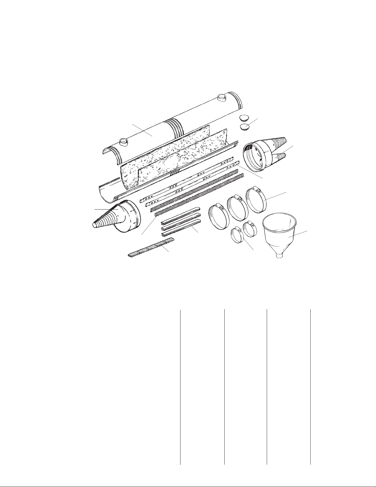
2.0 Kit Contents
2.1 The kit contents are shown below:
Snap-in Caps
Double End Cap
Strain Relief Bars
Large Hose Clamps
Funnel
Single End Cap
Closure Body
Insulating Sleeves
Foam Strips
Locking "H"
Small Hose Clamps
Visually inspect all components. If any component is missing or appears damaged, do not install and call 3M
Customer Service at 1-800-426-8688 for a replacement product.
883656
2.2 The following materials are included in each 3M™ Better Buried Closure Kit:
B.B. B.B. B.B. B.B. B.B.
SB/2SC SB/SC,DC SB/2DC SB/DC,TC Sleeve Kit
Kit Components 2" - 5" 2" - 5" 6" - 9" 7" - 9" 2" - 9"
(50mm-127mm) (50mm-127mm) (152mm-229mm) (178mm-229mm) (50mm-229mm)
Closure Body 1 1 1 1 1
End Cap, Single (SC) 2 1
End Cap, Multiple (DC) (TC) 1 2 2
Spacer Web (SW) 1 1 1 1 1
Strain Relief Bar (SB) 1 or 2 1 or 2 2 2
Hose Clamps, Closure 3 3 3 3 3
Hose Clamps, Strain Bar 2 2 2 2
Funnel 1 1 1 1 1
Snap-In Cap 2 2 2 2 2
Locking "H" 2 3 or 4 4 5
Foam Strips 1 1 1 1
3
Page 4

2.3 Additonal Materials Required (Dependent on Kit Contents):
• Shield Connectors • Better Buried Sleeve Kits (Closure Extension)
• Encapsulating Compound (permanent or • Hose Clamps
reenterable) • Vinyl Tape
• 3M
• Sheath Scuff Material • Scotch
• Pair Saver • Scotch
• 3M
™
Scotchcast™ Spacer Web 4430 (for reentry only) • DR Tape
™
Scotchcast Strain Relief Bar Kits 4465 or 4465-L • B Sealing Tape
®
Linerless Rubber Splicing Tape 130C
®
Vinyl Mastic Tape
• Moisture Resistant Splicing Connectors • Bonding Braid
• Better Buried End Caps (bulk)
3.0 Closure Selection Guide
3.1 Select proper closure using the following tables.
3.2 Maximum Splice Bundle Capacities (Straight Splice)
Connector 2" x 12" 2" x 24" 3"x 24" 4" x 24" 5" x 26" 6 x 26" 7 x 26" 9 x 26"
50 x 305mm 50 x 610mm 76 x 610mm 102 x 610mm 127 x 660mm 152 x 660mm 178 x 660mm 229 x 660mm
3M™ MS
2™
50 pair 100 pair 200 pair 400 pair 600 pair 900 pair 1200 pair 2400 pair
Splicing Module 0.5 mm 0.5 mm 0.5 mm 0.5 mm 0.5 mm 0.5 mm 0.5 mm 0.4 mm
4000-DWP (24 AWG) (24 AWG) (24 AWG) (24 AWG) (24 AWG) (24 AWG) (24 AWG) (24 AWG)
UY Only
3M™ Scotchlok
™
25 pair 50 pair 100 pair 200 pair 300 pair 400 pair 600 pair 900 pair
Connectors UR 0.6 mm 0.6 mm 0.6 mm 0.6 mm 0.6 mm 0.6 mm 0.6 mm 0.6 mm
(w/ 3" pigtails) (22 AWG) (22 AWG) (22 AWG) (22 AWG) (22 AWG) (22 AWG) (22 AWG) (22 AWG)
3.3 Closure Dimension Guide
Closure End Cap Port Diameters Maximum Splice Openings Approx.
Amount
Single Multiple Entry (Max.) Double Sheath of Comp.
Entry Single Required
Closure Size (Max.) 1 2 3 Sheath Outer Inner (Ave. Splice)
2" x 12" 1.2" 1.2" 0.7" - 5" - - 21 oz.
(50 x 305 mm) 30 mm 30 mm 18 mm 127 mm 600 gms
2" x 24" 1.2" 1.2" 0.7" - 17" 17" 14" 42 oz.
(50 x 610 mm) 30 mm 30 mm 18 mm 432 mm 432 mm 356 mm 1200 gms
3" x 24" 1.6" 1.6" 1.0" - 17" 17" 14" 106 oz.
(76 x 610 mm) 41 mm 41 mm 25 mm 432 mm 432 mm 356 mm 3000 gms
4" x 24" 2.0" 2.0" 1.5" - 17" 17" 14" 159 oz.
(102 x 610 mm) 51 mm 51 mm 38 mm 432 mm 432 mm 356 mm 4500 gms
5" x 26" 2.4" 2.4" 1.8" - 19" 19" 16" 254 oz.
(127 x 660 mm) 61 mm 61 mm 46 mm 483 mm 483 mm 406 mm 7200 gms
6" x 26" 3.3" 2.7" 2.0" 1.5 19" 19" 16" 441 oz.
(152 x 660 mm) 84 mm 68 mm 50 mm 40 mm 483 mm 483 mm 406 mm 12500 gms
7" x 26" 3.5" 3.5" 2.2" 2.2 19" 19" 16" 530 oz.
(178 x 660 mm) 89 mm 89 mm 56 mm 56 mm 483 mm 483 mm 406 mm 15000 gms
9" x 26" 4.0" 4.0" 2.5" 2.5 19" 19" 16" 742 oz.
(229 x 660 mm) 102 mm 102 mm 64 mm 64 mm 483 mm 483 mm 406 mm 21000 gms
Note: All metric conversions are approximate.
4
Page 5

4.0 LHS End Cap Installation
4.1 End Cap Installation on Cut Cables
Procedure:
a. Select desired port(s).
b. Cut off cone(s) as close as possible to the
diameter of the cable using the cut guides
on either side of the cone(s). See cable
diameter tape on back cover.
Metric DesignationEnglish Designation
c. When not slitting cap, place piece of foam
in each slot on inside of cap.
Foam Tape
Inside End View
d. Push cable through port and slide end cap
down cable so not to interfere with cable
preparations or splicing.
DO NOT SLIT END CAP UNLESS
INSTALLING ON EXISTING CABLE.
4.2 End Cap Installation on Straight Through
or Express Cable Procedure:
a. Select desired port(s).
b. Cut off cone(s) as close as possible to the
diameter of the cable using the cut guides
on the cone(s). See cable diameter tape on
back cover.
c. Slit end cap between raised guide rails.
842844
883656
Slit
5.0 Cable Preparations
5.1 Position and secure cables according to the
splice opening for the closure size selected.
See closure dimension guide for the maximum
splice openings.
5.2 Scuff 6" (152 mm) of outer sheaths as shown.
5.3 Wrap all scuffed areas with vinyl tape.
Note: Vinyl tape should be removed from under
Shield Bond Connectors when installed.
5.4 Remove outer sheath for a splice opening no
greater than the maximum splice opening
listed for closure size in closure dimension
guide.
5.5 Remove shield flush with outer sheath.
5.6 Clean filled cable for good encapsulant
adhesion and sealing.
5.7 Single Sheath Cables Procedure:
6" (152mm) Scuff
88T
6" (152mm) Scuffed
and Temporarily
Wrapped
a. Insert base assemblies of shield connectors
between the core wrapper and the shield
180° apart. Insert base assemblies of shield
connectors between the core wrapper and
the shield 180° apart. Install first nut and
torque to 45 ± 5 in-lbs (5.2 ± 0.6 kg·m).
Single Sheath
Core Wrapper
3/4" (19 mm)
Sheath Scuff
883655
180°
883657
842845
d. Place cap around cable.
e. Slide locking "H" Strip into place over the
raised guide rails. Start at the large (body)
end and work towards the small end of the
cone. Cut "H" Strip to length.
842846
"H" Strip in Place
842847
f. Slide end cap down so not to interfere with
cable preparations or splicing.
Note: Use only 1 (one) sheath connector on each
cable for the 2" (50 mm) diameter closures.
b. Trim core wrapper, leaving 3/4" (19 mm).
c. Install insulation sleeve on strain relief
bar(s). Trim length if necessary to clear
mounting holes.
d. Install one strain relief bar on Shield Bond
Connectors (to hold splice opening and
provide temporary bond.)
Note: Branch cables should be bonded according
to illustrations. If necessary, shield
connector studs may be trimmed to clear
cover halves of smaller diameter closures.
5
Page 6

3" – 9" Kits
Strain Relief Bar
2" Kit
Strain Relief Bar
Bonding Braid
883657
e. Splice conductors per standard procedure.
f. Insert base assemblies of the shield
connectors between the inner sheath
and the shield, 180° apart. Insert base
assemblies of shield connectors between
the core wrapper and the shield 180° apart.
Install first nut and torque to 45 ± 5 in-lbs
(5.2 ± 0.6 kg·m).
180°
f. To insure thorough encapsulation of
conductors, do not tightly bind the splice
bundle.
g. Install second bond bar if required.
h. Remove vinyl tape from scuffed sheaths.
Keep these areas clean during the
following bonding and sealing collar
construction operations.
i. Build outer sheath sealing collars just
beyond ends of strain relief bar(s). Sealing
collars are one wrap of 3/4" (19 mm) B
sealing tape. Completely overwrap with
highly stretched DR tape (white side out.)
DR Tape
B Sealing Tape
883657
j. Install hose clamps over ends of strain
relief bar(s).
Note: Rotate hose clamps so heads will not
obstruct fill ports on body.
k. Overwrap strain relief hose clamps with DR
tape to keep hose clamps tails from flagging.
5.8 Double Sheath Cables Procedure:
6" (152mm)
Scuff
6" (152mm) Scuff
Inner Sheath
1-1/2" (38 mm)
88T
Double Sheath
883658
Note: Use only 1 (one) shield connector on each
cable for 2" (51 mm) diameter closures.
g. Build inner sheath sealing collars on
exposed inner sheaths. Sealing collars are
one wrap of 3/4" (19 mm) B sealing tape
completely overwrapped with highly
stretched DR tape (white side out).
h. Cover inner sheath sealing collars with
vinyl tape to protect them from
contamination of grease and dirt.
i. Remove core wrap even with inner sheath.
j. Install insulation sleeve on strain relief
bar(s). Trim to length if necessary to clear
mounting holes.
™
k. Install one strain relief bar on 3M
Scotchlok
™
Shield Bond Connectors (to hold
splice opening and provide temporary bond).
Note: Branch cables should be bonded according
to illustrations. If necessary, shield
connector studs may be trimmed to clear
cover halves of smaller diameter closures.
3" – 9" Kits
Strain Relief
Bars
Sheath Scuff
883658
a. Remove outer sheath and shield for a
splice opening no greater than the
maximum splice opening listed for
closure size in closure dimension guide.
b. Scuff 6" (152 mm) of outer sheath.
c. Wrap scuffed sheath with vinyl tape.
Note: Vinyl Tape should be removed from under
Shield Bond Connector when installed.
d. Scuff 2" (51 mm) of inner sheath.
e. Remove inner sheath, except for 1-1/2"
(38 mm) at both ends of splice opening.
2" Kit
Inner Sheath Sealing Collar
Bonding Braid
l. Splice conductors per standard procedure.
m. To insure thorough encapsulating
compound penetration, do not tightly bind
the splice bundle.
®
n. Remove Scotch
Vinyl Tape 88T from
scuffed sheath(s) and inner sheath sealing
collars. Keep these areas clean during
the following bonding and sealing collar
construction operations.
6
883658
Page 7

o. Install second bond bar if required.
p. Install hose clamps over ends of strain
relief bars.
Note: Rotate hose clamps so heads will not
obstruct fill ports on body.
q. Overwrap the strain relief hose clamps
with DR tape to prevent hose clamp tails
from flagging.
r. Build outer sheath sealing collars just
beyond ends of strain relief bars. Outer
sheath sealing collars are one (1) wrap of
3/4" (19 mm) B sealing tape completely
overwrapped with highly stretched DR
tape (white side out).
DR Tape
1/2"
13mm
883660
6.7 Mix compound according to instructions.
Note: Carefully follow health, safety and
environmental information on product
label or Material Data Sheet for
encapsulating compound being used.
6.8 Position closure in final position to be buried,
then fill closure with compound. Continue
mixing and pouring compound until closure is
completely filled and trapped air is removed.
B Sealing Tape
883659
6.0 Closure Assembly
Note: Make sure all vinyl tape has been removed
from splice encapsulation area.
6.1 Center lower closure half on splice bundle and
attach upper half (upper half has fill ports)
mating the tongue and groove.
883659
6.2 Place one large hose clamp around center of
closure and tighten.
6.3 Set end caps in grooves on closure body ends
and secure with large hose clamps. Seal end
caps to cable sheaths with 2 half-lapped layers
of vinyl tape. Start the half-lap layers on the
cable and tape up the cone.
6.9 Close fill ports with the snap-in caps.
6.10 Check for any compound leaks. If leaks are
observed, tighten hose clamps and retape as
required.
6.11 Closure can be buried immediately.
7.0 Closure Reentry
7.1 Remove hose clamps from closure and end
caps. Remove any tape from end caps.
7.2 With a twisting motion, pull end caps from
closure and slide down cable.
7.3 Grasping closure at one end, slowly separate
halves from encapsulant.
7.4 Remove spacer web from splice and discard.
DO NOT REUSE THIS SPACER WEB.
7.5 Tear cured encapsulant away, as necessary, to
access splice.
™
7.6 After completion of repair, place 3M
Scotchcast™ Spacer Web 4430 around splice
and reassemble closure as outlined in Section
6.1 - 6.3. End caps and sleeves can be
reused.
883659
6.4 Position closure for burial on firmly packed
earth. Avoid sharp bends or kinks in the cable.
6.5 Slightly incline one closure end about 1/2"
(13 mm). Properly place supports under the
closure for compound filling.
6.6 Insert funnel into lower closure fill port.
(During filling, air will escape from higher
end.)
Note: If original end caps are reused, place a
small piece of B-sealing tape in slots on
inside of caps.
Note: Be sure that the spacer web 4430 does not
block the fill ports.
7.7 Fill closure with new compound as outlined in
Sections 6.4 - 6.11.
7
Page 8

8.0 Closure Extension
8.1 Cut a closure body in half using a cable saw
or similar tool. Cut grooves are provided on
closure bodies.
9.2 Force service wire through port.
8.2 Assemble the closure by staggering the cut
sections. Position hose clamps. Tape seams
with LR tape or vinyl tape.
Half Body Top Full Body Top
Full Body Bottom Half Body Bottom
75350
8.3 Fill closure with compound as outlined in
Sections 6.4 - 6.11.
9.0 Adding Service Wires (2" - 5",
50mm - 125mm Closures)
9.1 Cut a small "+" pattern through the service
wire port.
883661
883661
9.3 Scuff service wire sheath that will be located
inside closure. Build a sealing collar on
each service wire. Service wire collars are
one wrap of 3/4" B sealing tape completely
overwrapped with highly stretched DR tape
(white side out). Align the service wire
sealing collars directly over the outer sheath
sealing collars on main cable.
DR Tape
Service Wire
Sealing Collar
812027
9.4 Bond per standard procedure.
9.5 Install end cap. (See Section 4). Tighten hose
clamps.
9.6 Complete closure assembly per Sections 5
and 6.
3M, Scotchcast, Scotchlok and MS2 are trademarks of 3M Company.
Important Notice
All statements, technical information, and recommendations related to 3M’s products are based on information believed to be reliable, but the
accuracy or completeness is not guaranteed. Before using this product, you must evaluate it and determine if it is suitable for your intended
application. You assume all risks and liability associated with such use. Any statements related to the product which are not contained in
3M’s current publications, or any contrary statements contained on your purchase order shall have no force or effect unless expressly agreed
upon, in writing, by an authorized officer of 3M.
Warranty; Limited Remedy; Limited Liability.
This product will be free from defects in material and manufacture for a period of one (1) year from the time of purchase. 3M MAKES NO
OTHER WARRANTIES INCLUDING, BUT NOT LIMITED TO, ANY IMPLIED WARRANTY OF MERCHANTABILITY OR FITNESS FOR
A PARTICULAR PURPOSE. If this product is defective within the warranty period stated above, your exclusive remedy shall be, at 3M’s
option, to replace or repair the 3M product or refund the purchase price of the 3M product. Except where prohibited by law, 3M will not
be liable for any indirect, special, incidental or consequential loss or damage arising from this 3M product, regardless of the legal
theory asserted.
Communication Markets Division
3M Telecommunications
6801 River Place Blvd.
Austin, TX 78726-9000
800.426.8688
Fax 800.626.0329
www.3MTelecommunications.com
Recycled paper
40% Pre-consumer waste paper
10% Post-consumer waste paper
Litho in USA
© 3M 2006 78-8135-4353-1-A
 Loading...