

Page 1
Instruction Manual
3
718 Static Sensor
Safety Information
Intended Use
The 3M™ 718 Static Sensor is a portable,
handheld instrument designed for measuring
voltages associated with electrostatic charge.
Its intended use is for measuring the amount
of voltage, in a range from 0-20 kilovolts,
associated with an electrostatic charge
buildup on a surface. Any deviation from
this intended use could impair the
instrument’s effectiveness and possibly lead
to an unsafe operating condition.
The 3M™ 718A Air Ionizer Test Kit is a
set of accessories for use in conjunction
with the 3M 718 Static Sensor. Their
intended use is for verifying the operation of
air ionizers by measuring the neutralization
time for a static charge placed on a
stationary metal plate. Any deviation
from this intended use could impair the
instrument’s effectiveness and possibly lead
to an unsafe operating condition.
Caution Statements
• The 718 Static Sensor and 718A Charger
use DC 9V power supplied by a 9V
alkaline battery. Usage of any other
power source may cause damage to the
instruments.
• The 718 Static Sensor and 718A Air
Ionizer Test Kit have no user-serviceable
parts. Do not disassemble the products for
any reason. UNAUTHORIZED SERVICE WILL VOID THE WARRANTY.
• The 718 and 718A are NOT designed for usage in hazardous environments where the
possibility of explosion or fire exists.
Read and understand all safety information before installing and operating
this equipment.
Page 2

Page 3
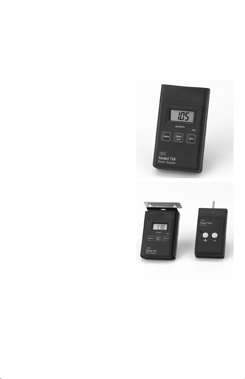
1.0 Description
The 3M™ 718 Static Sensor is a portable
handheld instrument used for locating and
measuring electrostatic charges. It can be
used to locate ESD trouble-areas, and is a
valuable tool for the ESD-control
engineer. Used in conjunction with the
3M™ 718A Air Ionizer Test Kit (available
separately), it can be used for verification
and auditing of air ionizers.
The 718 Static Sensor is battery-powered
and has several measurement features:
Range: measurements can be taken in a 02 kV or 0-20 kV range.
Automatic Zero: pushbutton feature
allows easy adjustment to zero. No screws
or dials to turn.
HOLD function: allows the User to
"freeze" a displayed measurement, for
later evaluation.
Automatic shutoff: conserves battery
power by shutting off the instrument after
20 minutes of inactivity.
2.0 Power Requirements and
Battery Installation
2.1 Both the 718 and 718A Charger us
DC 9V power supplied by a 9V
alkaline battery.
2.2 To install the battery on either unit:
2.2.1 Remove the battery cover, located in
the lower back of the unit. To do
this, press down on the cover and
slide it downward.
2.2.2 Pull the battery connector out of the
housing, and align the male/female
ends of the connector with the
proper terminals on the battery.
2.2.3 Connect the two, and place the
connected battery into the housing
by inserting the connector end first,
then following up with the other end
of the battery.
2.2.4 Replace the cover.
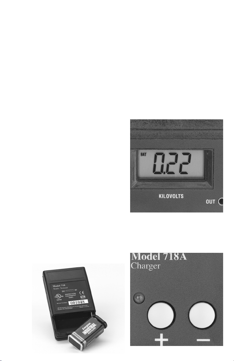
2.3 The 718 Static Sensor has a Low
Battery indicator. Once the battery is
depleted to approximately 6.5 volts,
the instrument will show BAT in the
display. At this time, the 718 will not
produce accurate results and the
battery should be replaced. A fresh
alkaline battery should last greater
than 50 hours, when the instrument is
in continuous usage.
2.4 The 718A Charger also has a low-
battery indicator. This is an LED
located at the left-hand side of the
unit. When the battery voltage drops
below operating level, the LED will
light up. At this time, the user should
Page 4
replace the battery. Usage of the
3M™ 718A Charger under lowbattery conditions would lead
to insufficient voltage levels
being generated.
3.0 Operation of the 718 Static
Sensor
Supplemental notes:
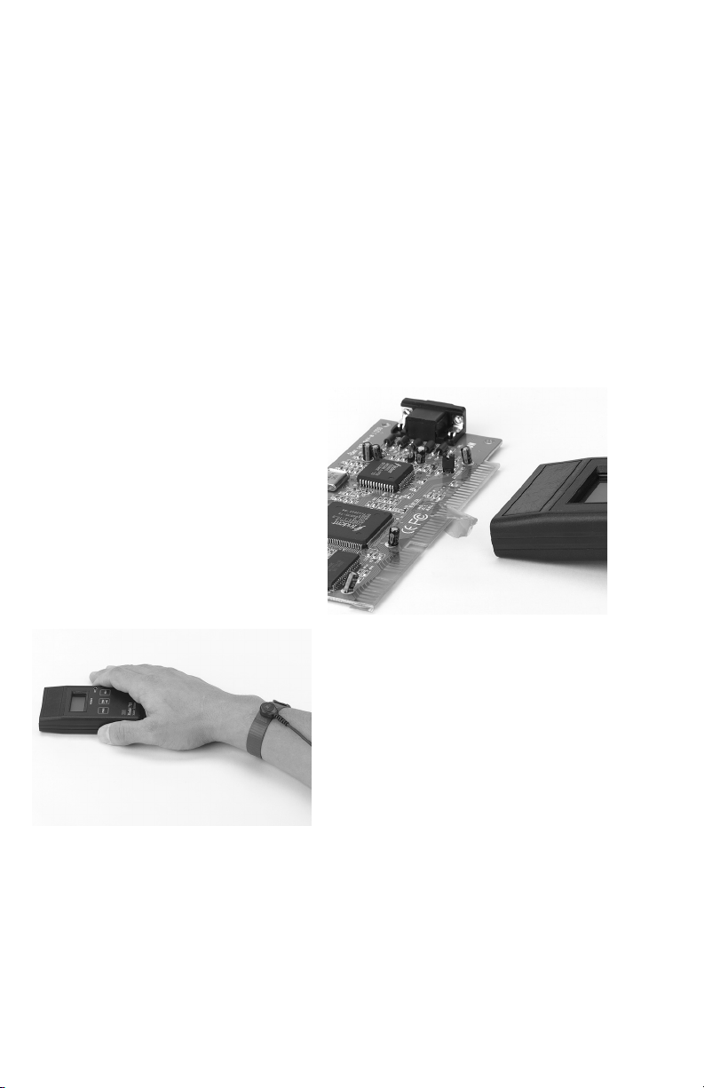
For accurate measurements during usage,
it is recommended that the outside housing
of the 3M™ 718 Static Sensor be
connected to an electrical ground. This
can be accomplished by having the user
holding the instrument connected to
ground through either a static control wrist
strap, or while wearing static control
footwear. The enclosure of the 718 is
made of conductive plastic and is,
therefore, electrically connected to
whomever is holding the instrument. In
addition, ground for the instrument can be
provided through the Voltage Monitor
Output on the front of the case.
The 718 Static Sensor is a precision
electronic instrument. Improper use or
rough treatment can damage the unit, and
render it incapable of providing accurate
measurements.
3.1 Turning the unit ON and OFF: To
turn on the 718 Static Sensor,
momentarily press down on the
membrane switch labeled POWER.
Determining that the power is on can
be verified by seeing that the liquidcrystal display (LCD) is on, and that
the red light-emitting diodes in the
front of the sensor are lit. To shut off
the 718 Static Sensor, momentarily
press down on the membrane switch
labeled POWER. Determining that
the power is off can be verified by
seeing that the liquid-crystal display
(LCD) is off.
3.2 Making Electrostatic Voltage
Measurements: hold the instrument 1inch (2.54 cm) away from the object
being measured. The display will
update with the voltage measurement
in kilovolts. If the measured voltage
is greater than the measurement range
of the instrument, a –1. will be
displayed. At this time, switch to
a greater range. If over-ranging
occurs even with the 20 kV range
activated, the static charge on the
object cannot be measured with the
718 Static Sensor.
3.3 Measurement Range: all measurements
are in kilovolts (kV) as stated on the
front label of the unit. The 718 has
two measurement ranges: 0-2 kV and
0-20 kV. The unit’s current
measurement range mode can be
verified by checking the display.
Three digits following the decimal
point indicate that the unit is in 0-2 kV
range. Two digits following the
decimal point indicate that the sensor
is in 0-20 kV range. To change
between measurement ranges, press
the RANGE/HOLD button once,
momentarily.
3.4 HOLD Function: in the event that the
user wishes to freeze the current
measurement, the HOLD function of
the 718 Static Sensor may be used.
Simply press the HOLD switch
momentarily and the currently
displayed voltage will be frozen.
Page 5

A HOLD notice will also be
displayed to alert the user that the
instrument is currently in HOLD
status. To unfreeze the display and
return to floating measurement,
momentarily press the HOLD switch
once again. Please note that during
HOLD condition the distanceindicating LED’s are turned off.
3.5 Zero adjustment: the 3M™ 718 Static
Sensor has a zero adjustment
function, which sets a zero reference
point for all subsequent
measurements. This zero reference
can be set by pointing the instrument
at a known zero-voltage surface, and
holding down the RANGE/ZERO
button for longer than 3 seconds.
After 3 seconds, the display will flash
and adjust to zero. Repeat this step
for both the 2 kV and the 20 kV
ranges. The zero adjustment should
be performed every time the unit is
turned on.
3.6 Measurement Accuracy:
3.6.1 Distance Indicator: the 718 Static
Sensor is factory calibrated to give
accurate measurements when it is
placed one inch (2.54 cm) away
from the object to be measured. To
assist the user in gauging this
distance, two light-emitting diodes
(LED’s) are present on the front face
of the instrument. These LED’s
emit two red, bullseye targets on the
surface of the object being measured.
As the instrument gets closer to the
one inch measurement distance, the
bullseyes begin to converge. When
they converge and become one, the
instrument is approximately one
inch away, and the measurement can
be made.
For more accurate measurements,
it is recommended that the user
manually measure the distance
between the front housing of the
instrument and the object
being measured.
3.6.2 Accuracy and Size of Object to be
Measured: the minimum surface
area on an electrostatically charged
object which can be accurately
measured is a 5 square inch
(32.3 cm
2
) area.
3.6.3 Measurements from Greater than
One Inch (2.54 cm) Away: in the
event that a one inch separation
between object-to-be measured and
the 718 cannot be achieved, it is
possible to get approximate
readings. This can be accomplished
by holding the instrument at
multiples of one inch (two inches,
three inches, etc.) away from the
object. The measurement reading is
then adjusted according to the
following equation:
Measurement distance (in inches) x
displayed voltage (in kilovolts) =
approximate voltage in kilovolts
Page 6

3.7 Continuous Output: an output jack is
provided on the front of the 3M™
718 Static Sensor. This output can
be used to feed a continuous signal
into a data storage device for
continuous monitoring of measured
voltages. Please use a 3/32 inch (2.5
mm) mono-phone plug to connect
into the output jack. The output is
designed to drive a digital voltmeter
with an input impedance of greater
than 50 kΩ. The output signal is
dependent on the measurement range
currently selected. For the low (2
kV) range, the output signal is 1/1000
of the measured electrostatic voltage.
For the high (20 kV) range, the
output signal is 1/10,000 of the
measured voltage.
3.8 Automatic Shut-Off: the 718 Static
Sensor will automatically shut-off 20
minutes after the last switch activity.
This is done in order to conserve
battery power. In the event that the
user needs to have the unit stay ON
continuously, when turning the unit
on depress the POWER AND
RANGE switches simultaneously.
This deactivates the Automatic ShutOff feature. The BAT indicator will
then flash three times to indicate that
the automatic shut-off features has
been disabled. The Automatic ShutOff feature will reset itself the next
time the instrument is turned on.
4.0 Operation and Use of the
718A Air Ionizer Test Kit
It is recommended that the user be familiar
with ionizer test standards ANSI/ESD S3.1
and draft standard ESD DSP3.3 if the
3M™ 718A Air Ionizer Test Kit is used to
perform verification testing on ionizer
performance.
4.1 Assembly: slide the charge plate over
the 718 Static sensor until it stops.
The charge plate slides onto the lower
groove, on the sides of the 718.
4.2 Charging the plate: holding the 718
Static Sensor (with charge plate
attached) in one hand, use the other
hand to touch the probe of the 718A
Charger to the charge plate. Press
either the
+ button (for a positive
voltage) or the
– button (for a negative
voltage), then remove the probe from
the charge plate. Be sure to keep the
button pressed while removing the
probe from the charge plate. The
display on the 3M™ 718 Static Sensor
will indicate a positive or negative
charging voltage (1.1kV minimum).
If a voltage of less than ±1.1kV is
displayed, check to see if the low
battery indicator on the 718A Charger
is illuminated. If illuminated, replace
the battery in the charger. If the unit
continues to supply an incorrect
voltage to the charge plate, please
contact 3M for additional instructions.
Page 7

4.3 Testing ionizer discharge time: after
charging the plate, hold the 718
approximately one foot (30.5 cm)
away from the ionizer. Monitor the
display to see how quickly the 1.1 kV
charge is dissipated to 0.1 kV. The
speed at which this occurs (the
discharge time) indicates how well
the ionizer is operating. Please refer
to the specific ionizer’s operating
manual or consult with the ionizer
manufacturer to determine what this
discharge time should be. Repeat this
procedure for both a positively and a
negatively charged plate.
4.4 Testing ionizer offset balance: zero
the charge plate by touching it with a
grounded object. This can either be
the finger of a grounded person or
some other item which is connected
to electrical ground. In either case,
zeroing the charge plate should make
the display on the 718 read zero.
Hold the 718 approximately one foot
(30.5 cm) in front of the ionizer.
Monitor the display. The value
displayed is the offset balance of the
ionizer, which is the difference
between the number of positive and
negative ions being emitted. Please
refer to the specific ionizer’s
operating manual or consult with the
ionizer manufacturer to determine
what this offset balance should be.
5.0 Service/Calibration
5.1 Service and Repair: in the event that
you believe the 718 Static Sensor or
the 3M™ 718A Air Ionizer Test Kit
is in need of repair, please contact
your local 3M representative for
troubleshooting help, and, as needed,
repair information. There are no
user-serviceable parts on either
product.
5.2 Calibration: the 718 and 718A
products are supplied by the factory
pre-calibrated. 3M does not specify a
minimum calibration cycle for the
718 or 718A products. The user,
usually according to internal Quality
procedures, determines calibration
cycles. 3M does offer calibration
services on these instruments. Please
contact your local 3M representative
for information on this service. In the
event that the user wishes to perform
a self-calibration, the following steps
should be followed for the 718 Static
Sensor (user-calibration not possible
on the 718A Air Ionizer Test kit).
5.3 Equipment Needed:
Test fixture
High-Voltage Power Supply,
capable of supplying voltages up
to 10,000 V
Voltmeter, with > 50 kΩ input
impedance, capable of measuring
voltages down to the µV range.
Cable with a 3/32 inch (2.5mm)
mono plug and secondary connector
to interface with voltmeter
Page 8

5.4 Test fixture:
Metal plate of at least 5 square
inches area (38.7 cm
2
) area.
Metal stand capable of supporting
718, and holding it one inch (2.54
cm) away from the metal plate,
centered.
Connectors on the plate with which
it can interface with the high voltage
power supply.
Connections on the metal stand with
which it can be connected to
electrical ground.
5.5 Procedure:
5.5.1 Place the 3M™ 718 Static Sensor on
the metal stand. Verify that it is
exactly one inch (2.54 cm) away from
the metal plate, and that its position is
centered relative to the plate.
5.5.2 Connect the stand to ground.
5.5.3 Turn on the 718 Static Sensor and
set it to the 2 kV range.
5.5.4 Ground the plate. Zero the display.
5.5.5 Remove the ground from the plate,
and connect it to the high voltage
power supply. Apply a 1 kV charge
to the plate.
5.5.6 The instrument should now be
reading 1.000. If it is not, remove
the battery door and use a
screwdriver to turn the small screw
located inside the battery
compartment. Use a small
screwdriver to turn the small screw,
located on the front right side of the
instrument. This screw should
adjust the reading on the display.
Once the display has been adjusted
to read 1.000, the low range of the
718 is now calibrated.
5.5.7 Repeat procedures 5.5.2 - 5.5.6 for
the 20 kV range of the meter, using
a test voltage of 5,000 volts.
Page 9

6.0 Physical Characteristics (All values typical)
(at 1 inch (2.54 cm) distance from sensor to target)
3M™ 718 Static Sensor
Dimensions 0.85" (H) x 2.4" (W) x 4.15" (L)
2.2 cm (H) x 6.1 cm (W) x 10.5 cm (L)
Weight 4.5 oz. (128 g) with battery
Operating Conditions 41º F - 95º F (5º C - 35º C)
up to 80% RH, non-condensing
Indoor use only
For use at altitudes below 42, 300 ft. (2000 m)
Pollution Degree II
Class III
Enclosure Conductive Polycarbonate
Power Requirements One 9-volt alkaline battery
Measurement Ranges 0 – 2 kV
0 – 20 kV
Voltage Display 3 1/2 digit liquid crystal display
Display Resolution 1 V/inch (0.39 V/cm) @ low range
10 V/inch (3.9 V/cm) @ high range
+/- 10 counts
Display Update Rate 3 Hz
Voltage Output Jack 3/32 in. (2.5 mm) monophone
Tip: signal
Sleeve: ground
Voltage Output 1/1000 of measured voltage @ low range
1/10,000 of measured voltage @ high range
Automatic Shut-off 20 minutes after last switch activity
Operating Time for Battery Greater than 50 hours, with new battery, @ 21º C
Continuous usage
Distance Indicator LED targets. Aligned targets indicate 1 in.
(2.54 cm) measurement distance
Measurement Accuracy within 5% of measured voltage
Measurement Stability ± 10 counts
Certifications UL, C-UL, CE, CB-scheme, NOM
3M™ 718A Air Ionizer Test Kit
Charge Plate Assembly Per ESD Association Draft Standard D3.3
Charge Plate Bracket Dimensions 1" (H) x 3.1" (W) x 4.25" (L)
Charge Plate Area 3.25" (W) x 1.25" (L)
Charge Plate Assembly Weight 2.5 oz (70 g)
Charger Dimensions 0.85" (H) x 2.4" (W) x 5.0" (L)
Charger Weight 6 oz. (170 g) with battery
Charger Power Requirements One 9 volt alkaline battery
Charger Output 1.1kV minimum for positive or negative voltage
(using 718 with charge plate)
Certifications UL, C-UL, CE, CB-scheme, NOM
Aluminum bracket
Bare stainless steel plate
PTFE spacers isolate plate from bracket
2.5 cm (H) x 7.9 cm (W) x 10.8 cm (L)
8.3 cm (W) x 3.2 cm (L)
2.2 cm (H) x 6.1 cm (W) x 12.7 cm (L)
Page 10

7.0 Parts Listing
3M™ 718 Static Sensor
1 ea. 718 Static Sensor
1 ea. 718/718A Operator’s Manual
1 ea. Certificate of Conformance
3M™ 718A Air Ionizer Test Kit
1 ea. 718A Charge Plate Assembly
1 ea. 718A Charger
1 ea. 718/718A Operator’s Manual
1 ea. Certificate of Conformance
8.0 Contact Information:
Customer and Technical Service
Within the U.S. : Customer service and
technical support can be obtained by
calling the 3M Electronic Handling &
Protection Division
Customer Service: (800) 328-1368
Technical Support: (512) 984-3200
Outside of the U.S.: For customer service
and technical support, please contact your
local representative of the 3M Electronic
Handling & Protection Division.
Page 11

Page 12

Electronic and Interconnect Solutions Division
6801 River Place Blvd.
Austin, TX 78726-9000
www.3m.com/eisd
3
Important Notice:
All statements, technical information,
and recommendations related to 3M’s
products are based on information
believed to be reliable, but the accuracy
or completeness is not guaranteed. Before
using this product, you must evaluate it and
determine if it is suitable for your intended
application.You assume all risks and
liability associated with such use. Any
statements related to the product which is
not contained in 3M’s current publications,
or any contrary statements contained on
your purchase order shall have no force
or effect unless expressly agreed upon,
in writing, by an authorized officer of 3M.
Warranty; Limited Remedy; Limited
Liability.
This product will be free from defects
in material and manufacture for a period
of one year from the time of purchase.
3M MAKES NO OTHER WARRANTIES
INCLUDING, BUT NOT LIMITED TO,
ANY IMPLIED WARRANTY OF
MERCHANTABILITY OR FITNESS
FOR A PARTICULAR PURPOSE.
If this product is defective within the
warranty period stated above, your
exclusive remedy shall be, at 3M’s option,
to replace or repair the 3M product or
refund the purchase price of the 3M
product. Except where prohibited by
law, 3M will not be liable for any indirect,
special, incidental or consequential loss
or damage arising from this 3M product,
regardless of the legal theory asserted.
Litho in USA
© 3M 2002
34-7051-6227-8
Recycled paper
40% pre-consumer waste paper
10% post-consumer waste paper
 Loading...