

Page 1
78-5102-0114-4 E
3M™
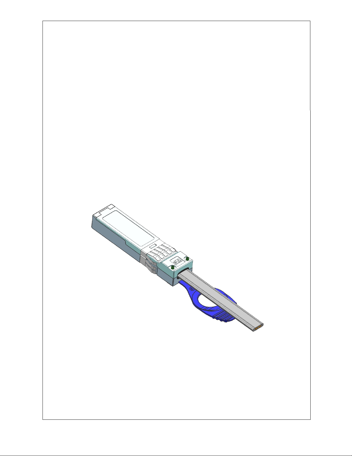
Cable Assembly
3
Division
Product Data Sheet
SFP+ Direct-Attach
Passive Copper
Electronics Materials Solutions
6801 River Place Blvd.
Austin, TX 78726-9000
http://www.3M.com/interconnects
Page 2

Page 3

Document Number: 78-5102-0114-4 E
Issue Date: May 10, 2017
Title: Product Data Sheet
Subject: 3M™ SFP+ Direct- Attach Passive Copper Cable Assembly
Page: 1 of 16
Table of Contents
1.0 SCOPE ............................................................................................................................................................... 2
2.0 PRODUCT TESTED ......................................................................................................................................... 2
3.0 GENERAL CONDITIONS ................................................................................................................................ 2
3.1 Test Specimens ....................................................................................................................................... 2
3.2 Standard Test Conditions ........................................................................................................................ 2
4.0 TEST RESULTS SUMM ARY .......................................................................................................................... 3
5.0 TESTING ........................................................................................................................................................... 4
5.1 General .................................................................................................................................................... 4
Visual (Appearance) — EIA-364-18 ....................................................................................................... 4
5.2 Environmental ......................................................................................................................................... 4
High Temperature Aging — EIA-364-17 ................................................................................................ 4
Low Temperature Aging — EIA-364-31 ................................................................................................. 5
Thermal Shock — EIA-364-32 ................................................................................................................ 6
Temperature and Humidity — EIA-364-31 ............................................................................................ 7
5.3 Mechanical .............................................................................................................................................. 8
Mating and Unmating Forces — ............................................................................................................ 8
Durability — ........................................................................................................................................... 8
Pull Tab and Mechanical Metal Latch Pull Strength — ........................................................................ 9
Signal Integrity...................................................................................................................................... 10
5.4
Voltage Modulation Amplitude(VMA) Loss — SFF 8431 Rev4.1......................................................... 10
VMA Loss to Crosstalk (VCR) Ratio - SFF 8431 Rev4.1 .................................................................... 10
Differential Output and I nput Reflection Coefficient (SDD
Common Mode Output and Input Reflection Coefficient (SCC
Difference Wavelength Distortion Pe nalty (dWDP) —SFF 8431 Rev4.1 ............................................. 15
and SDD22)— SFF 8431 Rev4.1............ 11
11
and SCC22) — SFF 8431 Rev4.1 ...... 13
11
Page 4
Document Number: 78-5102-0114-4 E
Issue Date: May 10, 2017
Title: Product Data Sheet
Subject: 3M™ SFP+ Direct Attach Passive Copper Cable Assembly
Page: 2 of 16
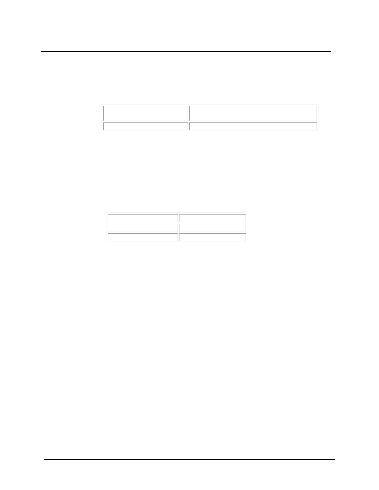
Product:
SFP+ Direct-Attach Passive Copper Cable
Assembly
Product Number:
1410, 1411, 1412 Series
Temperature:
15°C to 35°C
Relative Humidity:
45% to 75%
Atmospheric pressure:
650 to 800 mmHg
1.0 Scope
This data sheet summarizes test methods, test conditions and product performance for the 3M SFP+ Direct Attach
Passive Copper Cable Assembly
2.0 Product Tested
3.0 General Conditions
3.1 Test Specimens
The test specimens shall be strictly in compliance with the design, construction details and physical properties
detailed in the relevant Technical Specification Sheet (See Section 2).
3.2 Standard Test Conditions
The test shall be done under the following conditions:
Page 5
Document Number: 78-5102-0114-4 E
Issue Date: May 10, 2017
Title: Product Data Sheet
Subject: 3M™ SFP+ Direct Attach Passive Copper Cable Assembly
Page: 3 of 16
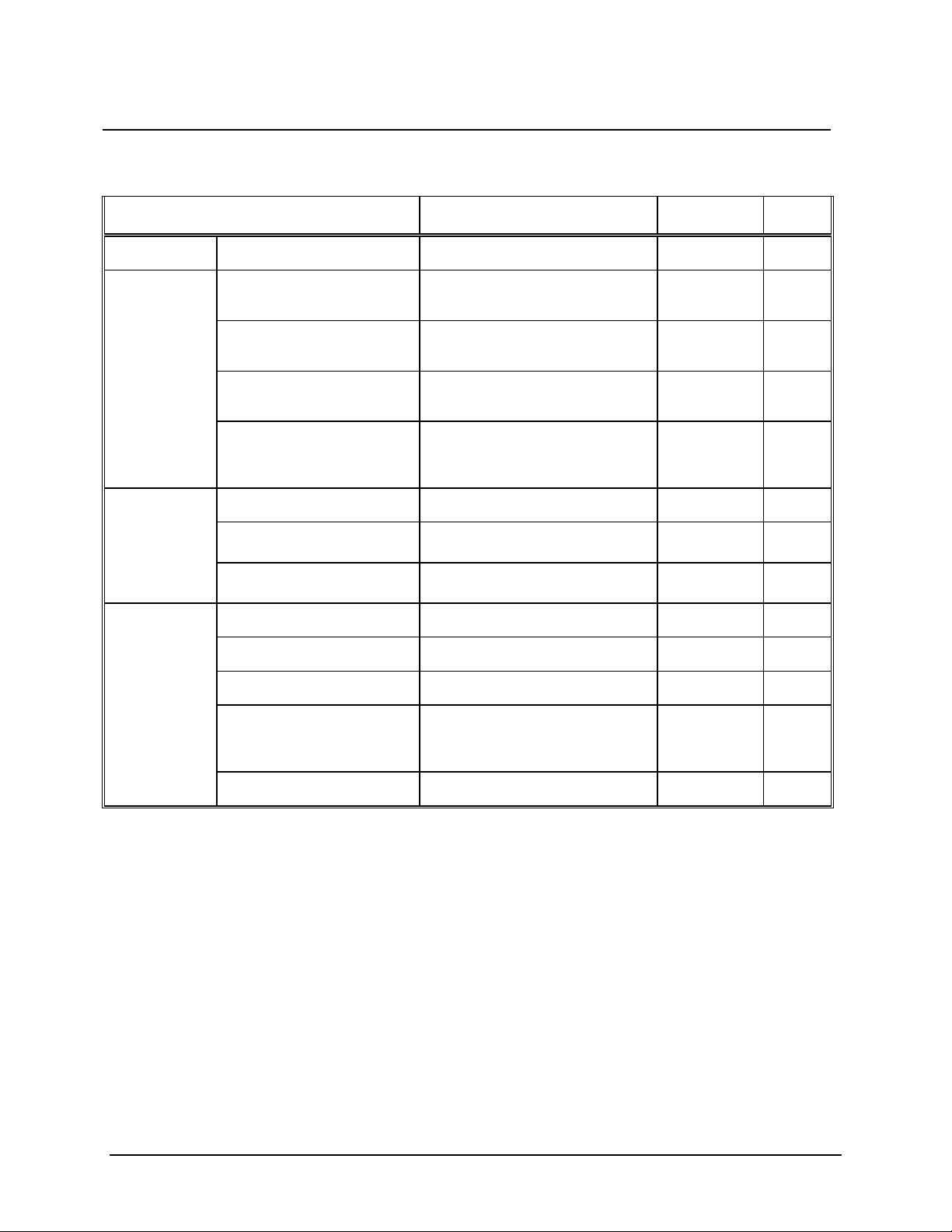
Items
SFF 8431 Rev 4.1
Test Method
Results
General
Visual
No defects such as deformation,
blister, damage, crack, etc.
EIA-364-18
Pass
Environmental
High Temperature Aging
No Physical abno r malit ies after test
85oC for 500 Hours
EIA-364-17
Low Temperature Aging
No Physical abnormalit ies after test
Measure Scc11 and Sdd21
EIA-364-17
Thermal Shock
No Physical abno r malit ies after test
Measure Scc
11
and Sdd21
EIA-364-32
Temperature and Humidity
No Physical abnormalit ies after test
Measure Scc
11
and Sdd21
EIA-364-31
Pass
Mechanical
Mating and Unmating Forces
Mating force: 18 N Max
Unmating force: 12.5 N Max
N.A
Pass
Durability
100 Flexing Test Cycles
N.A
Pass
Pull Tab and Mechanical Metal
No Physical damage of the P ull Tab
N.A
Pass
Signal Integrity
Voltage Modulation Amplitude
(VMA) Loss
<= 4.4 dB
SFF 8431 Rev4.1
Pass
VMA Loss to Crosstalk Ratio
(VCR)
> 32.5 dB
SFF 8431 Rev4.1
Pass
Differential Output and Input
Reflection Coefficient (SDDXX)
0.01 to 4.1 GHz 1
4.1 to 11.1 GHz
SFF 8431 Rev4.1
Pass
Common Mode Output and
0.01 to 2.5 GHz
3
SFF 8431 Rev4.1
Pass
Difference Wavelength
Dispersin Penalty
<= 6.75 dB
SFF 8431 Rev4.1
Pass
4.0 Test Results Summary
Latch Pull Strength
Input Reflection Coefficient
(SCC
)
XX
Measure Scc11 and Sdd21
Conditions: -30oC for 96 Hours
5 Cycles –30oC to +85oC
Cyclic test between 25 oC and 65 oC at
80-98% RH for 240 Hrs.
Measure Scc11 and Sdd21
and Mechanical Latch
2
4.1 to 11.1 GHz < -3 dB
Pass
Pass
Pass
1. Reflection Coefficient given by equation SDDxx(dB)= -12 + 2 × SQRT(f), with f in GHz.
2. Reflection Coefficient given by equation SDDxx(dB)= -6.3 + 13 × log10(f/5.5), with f in GHz.
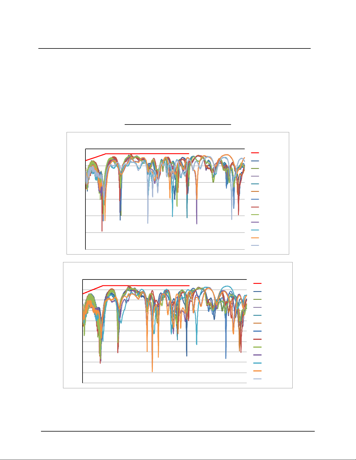
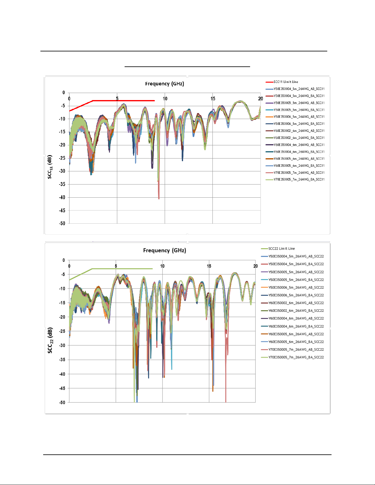
3. Reflection Coefficient given by equation SCCxx(d B) < -7 + 1.6 ×f, with f in GHz.
Page 6
Document Number: 78-5102-0114-4 E
Issue Date: May 10, 2017
Title: Product Data Sheet
Subject: 3M™ SFP+ Direct Attach Passive Copper Cable Assembly
Page: 4 of 16
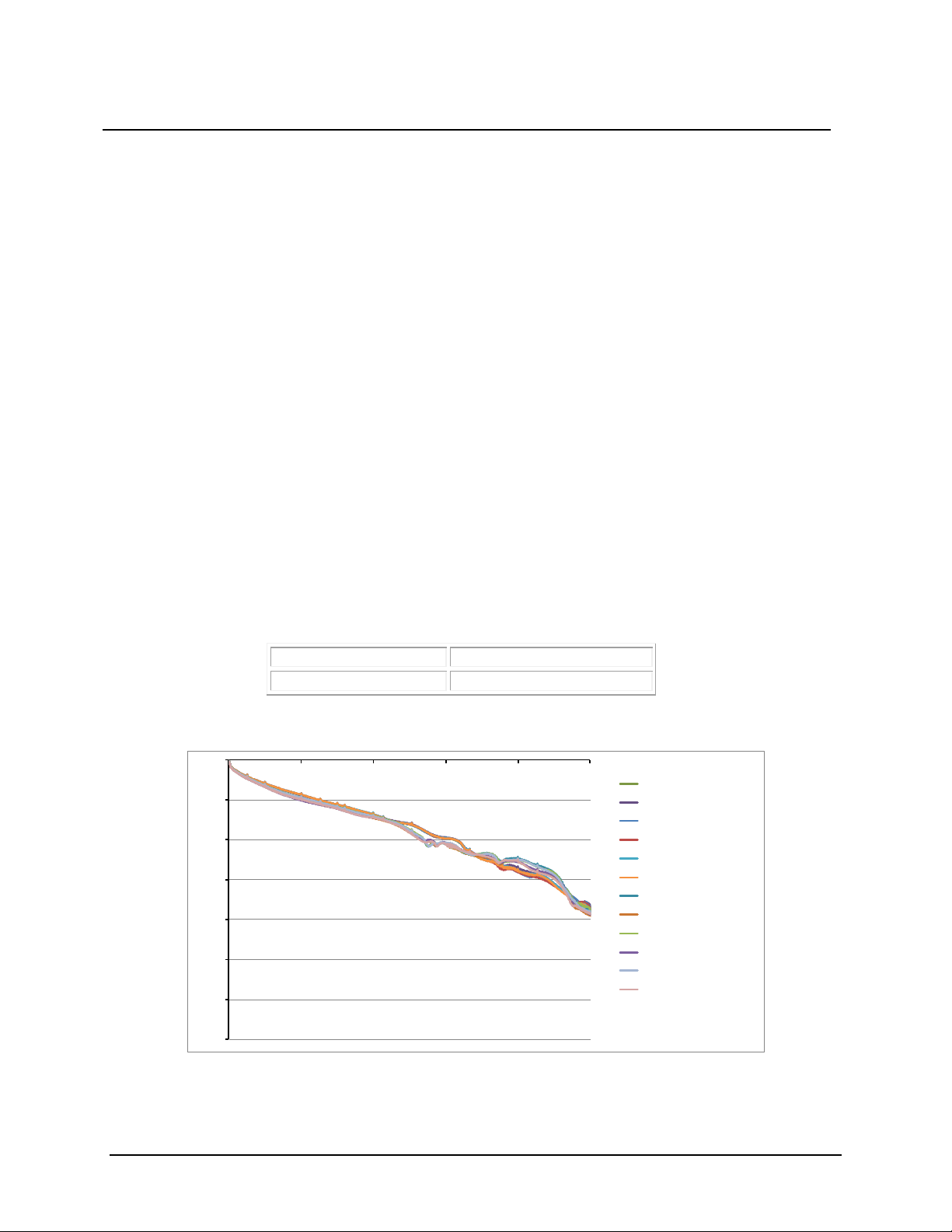
Temperature:
85°C
Duration:
500 hours
-70
-60
-50
-40
-30
-20
-10
0
0.00 3.00 6.00 9.00 12.00 15.00
C34_3M_Ch1_BT
C34_3M_Ch2_BT
C33_3M_Ch1_BT
C33_3M_Ch2_BT
C32_3M_Ch1_BT
C32_3M_Ch2_BT
C34_3M_Ch1_AT_500_Hrs_85° C
C34_3M_Ch2_AT_500_Hrs_85° C
C33_3M_Ch1_AT_500_Hrs_85° C
C33_3M_Ch2_AT_500_Hrs_85° C
C32_3M_Ch1_AT_500_Hrs_85° C
C32_3M_Ch2_AT_500_Hrs_85° C
Frequency(GHz)Frequency(GHz)
Sdd
21
(dB)
5.0 Testing
Test methods are based upon EIA Standard 364.
5.1 General
Visual (Appearance) — EIA-364-18
Purpose
The purpose of this test is to visually examine and dimensionally inspect the connector in order to determine whether
the connector conforms to the applicable specification and detail documents not covered by performance
requirements.
Test Method
The examination shall be made in accordance with EIA-364-18. The visual examination shall include inspection of
the following features as a minimum: workmanship, marking, materi als, finish, stand ards, design and constructi on.
The dimensional inspection shall be a check for compliance with the outline drawings of the detail specification.
5.2 Environmental
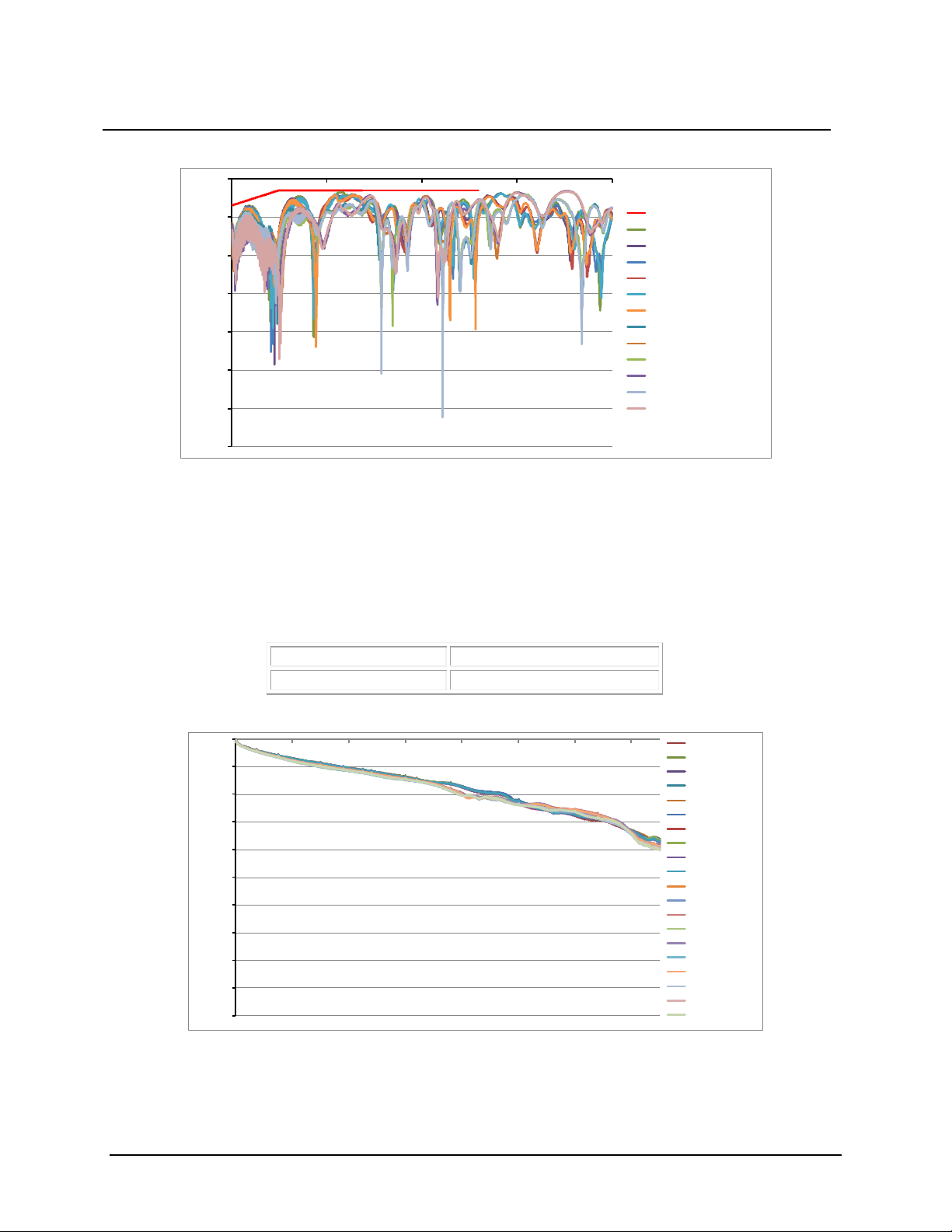
High Temperature Aging — EIA-364-17
Purpose
The purpose of this test is to determine the effects on the electrical and mechanical characteristics of the cable
assembly resulting from exposure of the cable assembly to an elevated ambient temperature fo r a specified length of
time.
Test Method
Mated connectors shall be tested in accordance with EIA-364 17.
Test Results
Page 7
Document Number: 78-5102-0114-4 E
Issue Date: May 10, 2017
Title: Product Data Sheet
Subject: 3M™ SFP+ Direct Attach Passive Copper Cable Assembly
Page: 5 of 16
-70
-60
-50
-40
-30
-20
-10
0
0 5 10 15 20
SFF 8431 Limit Line
C32_3M_Ch1_BT
C32_3M_Ch2_BT
C33_3M_Ch1_BT
C33_3M_Ch2_BT
C34_3M_Ch1_BT
C34_3M_Ch2_BT
C33_3M_Ch1_AT_500_Hrs_85° C
C33_3M_Ch2_AT_500_Hrs_85° C
C33_3M_Ch1_AT_500_Hrs_85
° C
C33_3M_Ch2_AT_500_Hrs_85° C
C34_3M_Ch1_AT_500_Hrs_85° C
C34_3M_Ch2_AT_500_Hrs_85
° C
Frequency (G hz)
SCC
11
(dB)
Temperature:
-30°C
Duration:
96 hours
-100
-90
-80
-70
-60
-50
-40
-30
-20
-10
0
0 2 4 6 8 10 12 14
C9_3M_IC_BT
C9_3M_OC_BT
C10_3M_IC_BT
C10_3M_OC_BT
C11_3M_IC_BT
C11_3M_OC_BT
C12_3M_IC_BT
C12_3M_OC_BT
C13_3M_IC_BT
C13_3M_OC_BT
C9_ 3M_I C_AT_
-30°
C
C9_ 3M_OC _AT_-30°C
C10_3M_IC_AT_-30° C
C10_3M_OC_AT_-30° C
C11_3M_IC_AT_-30° C
C11_3M_OC_AT_-30° C
C12_3M_IC_AT_-30° C
C12_3M_OC_AT_-30° C
C13_3M_IC_AT_-30° C
C13_3M_OC_AT_-30° C
Frequency(GHz)
Sdd
21
(dB)
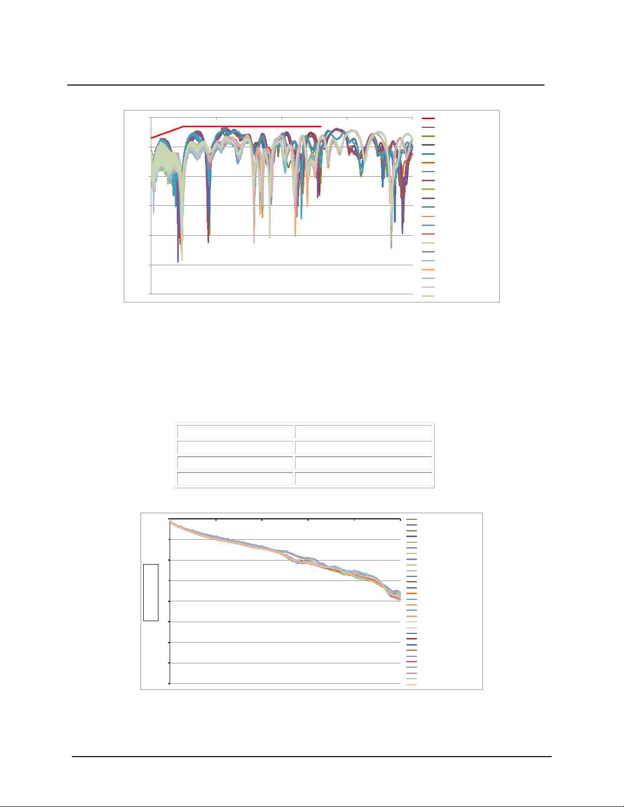
Low Temperature Aging — EIA-364-17
Purpose
The purpose of this test is to permit evaluation of the properties of materials used in cable assembly as they are
influenced or deteriorated by the effects of low temperature condition.
Test Method
Mated connectors shall be tested in accordance with EIA-364-17.
Page 8
Document Number: 78-5102-0114-4 E
Issue Date: May 10, 2017
Title: Product Data Sheet
Subject: 3M™ SFP+ Direct Attach Passive Copper Cable Assembly
Page: 6 of 16
-60
-50
-40
-
30
-20
-10
0
0
5 10 15
20
SFF 8431 Limit Line
C9_3M_IC_BT
C9_3M_OC_BT
C10_3M_IC_BT
C10_3M_OC_BT
C11_3M_IC_BT
C11_3M_OC_BT
C12_3M_IC_BT
C12_3M_OC_BT
C13_3M_IC_BT
C13_3M_OC_BT
C9_3M_IC_AT_-30° C
C9_3M_OC_AT_-30°C
C10_3M_IC_AT_-30° C
C10_3M_OC_AT_-30° C
C11_3M_IC_AT_-30° C
C11_3M_OC_AT_-30° C
C12_3M_IC_AT_
-30° C
C12_3M_OC_AT_-30
° C
C13_3M_IC_AT_-30° C
C13_3M_OC_AT_-30° C
Fre quency (GH z)
Scc
11
(dB)
Temperature:
-30°C and +85°C
Cycle Time:
30 minutes each Temperature
Transition Time:
1 minute maximum
Cycles:
5
-80
-70
-60
-50
-40
-30
-20
-10
0
0 3 6 9 12 15
C14_3M_Ch1_BT
C14_3M_Ch2_BT
C15_3M_Ch1_BT
C15_3M_Ch2_BT
C16_3M_Ch1_BT
C16_3M_Ch2_BT
C17_3M_Ch1_BT
C17_3M_Ch2_BT
C18_3M_Ch1_BT
C18_3M_Ch2_BT
C14 _3 M_Ch1_A T_30_Flex _Cycles
C14 _3 M_Ch2_A T_30_Flex _Cycles
C15 _3 M_Ch1_A T_30_Flex _Cycles
C15 _3 M_Ch2_A T_30_Flex _Cycles
C16 _3 M_Ch1_A T_30_Flex _Cycles
C16 _3 M_Ch2_A T_30_Flex _Cycles
C17 _3 M_Ch1_A T_30_Flex _Cycles
C17 _3 M_Ch2_A T_30_Flex _Cycles
C18 _3 M_Ch1_A T_30_Flex _Cycles
C18 _3 M_Ch2_A T_30_Flex _Cycles
C14_3M_Ch1_AT_30_Thermal_Shk
C14 _3 M_Ch2_A T_30__Th ermal_Sh k
C15_3M_Ch1_AT_30_Thermal_Shk
C15 _3 M_Ch2_A T_30__Th ermal_Sh k
C16_3M_Ch1_AT_30_Thermal_Shk
C16 _3 M_Ch2_A T_30__Th ermal_Sh k
C17_3M_Ch1_AT_Thermal_Shk
C17_3M_Ch2_AT_Thermal_Shk
C18_3M_Ch1_AT_Thermal_Shk
C18_3M_Ch2_AT_Thermal_Shk
Frequency(GHz)
Sdd
21
(dB)
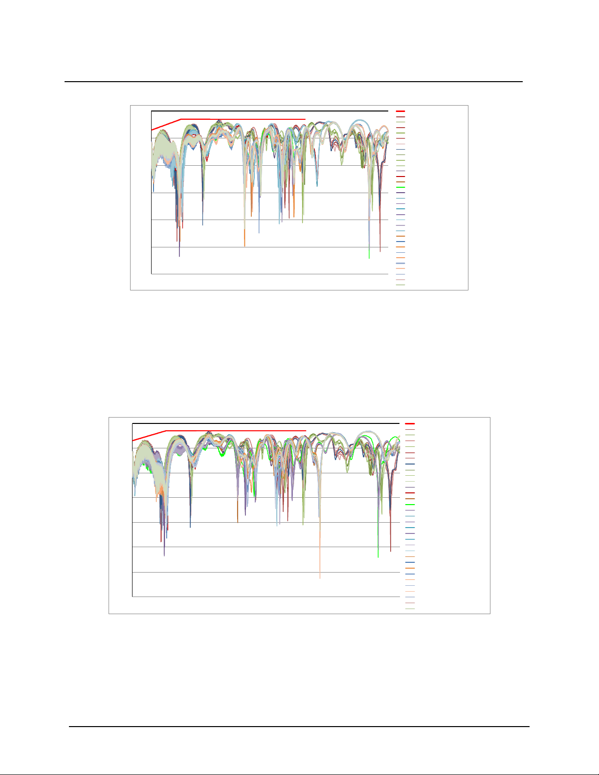
Thermal Shock — EIA-364-32
Purpose
The purpose of this test is to determine the resistance of a given cable assembly to exposure at extremes of high and
low temperatures and to the shock of alternate exposures to these extremes, simulating the worst probable conditions
of storage, transportation and applica tion.
Test Method
Mated connectors shall be tested in accordance with EIA-364-32.
Test Results
Page 9
Document Number: 78-5102-0114-4 E
Issue Date: May 10, 2017
Title: Product Data Sheet
Subject: 3M™ SFP+ Direct Attach Passive Copper Cable Assembly
Page: 7 of 16
-60
-50
-40
-30
-20
-10
0
0
5 10 15
20
Scc
11
(dB)
SFF 8431 Limit Line
C14_3M_Ch1_BT
C14_3M_Ch2_BT
C15_3M_Ch1_BT
C15_3M_Ch2_BT
C16_3M_Ch1_BT
C17_3M_Ch1_BT
C18_3M_Ch1_BT
C18_3M_Ch2_BT
C16_3M_Ch2_BT
C17_3M_Ch2_BT
C18_3M_Ch1_AT_30_Flex_Cycles
C18_3M_Ch2_AT_30_Flex_Cycles
C18_3M_Ch1_AT_30_Flex_Cycles
C18_3M_Ch2_AT_30_Flex_Cycles
C14_3M_Ch1_AT_30_Flex_Cycles
C14_3M_Ch2_AT_30_Flex_Cycles
C15_3M_Ch1_AT_30_Flex_Cycles
C15_3M_Ch2_AT_30_Flex_Cycles
C16_3M_Ch1_AT_30_Flex_Cycles
C16_3M_Ch2_AT_30_Flex_Cycles
C17_3M_Ch1_AT_30_Flex_Cycles
C17_3M_Ch2_AT_30_Flex_Cycles
C14_3M_Ch1_AT_30_Thermal_Shk
C14_3M_Ch2_AT_30__Thermal_Shk
C15_3M_Ch1_AT_30_Thermal_Shk
C15_3M_Ch2_AT_30__Thermal_Shk
C16_3M_Ch1_AT_30_Thermal_Shk
C16_3M_Ch2_AT_30__Thermal_Shk
C17_3M_Ch1_AT_30_Thermal_Shk
C17_3M_Ch2_AT_30__Thermal_Shk
C18_3M_Ch1_AT_30_Thermal_Shk
C18_3M_Ch2_AT_30__Thermal_Shk
Frequency(GHz)
-70
-60
-50
-40
-30
-20
-10
0
0 5 10 15 20
Scc
11
(dB)
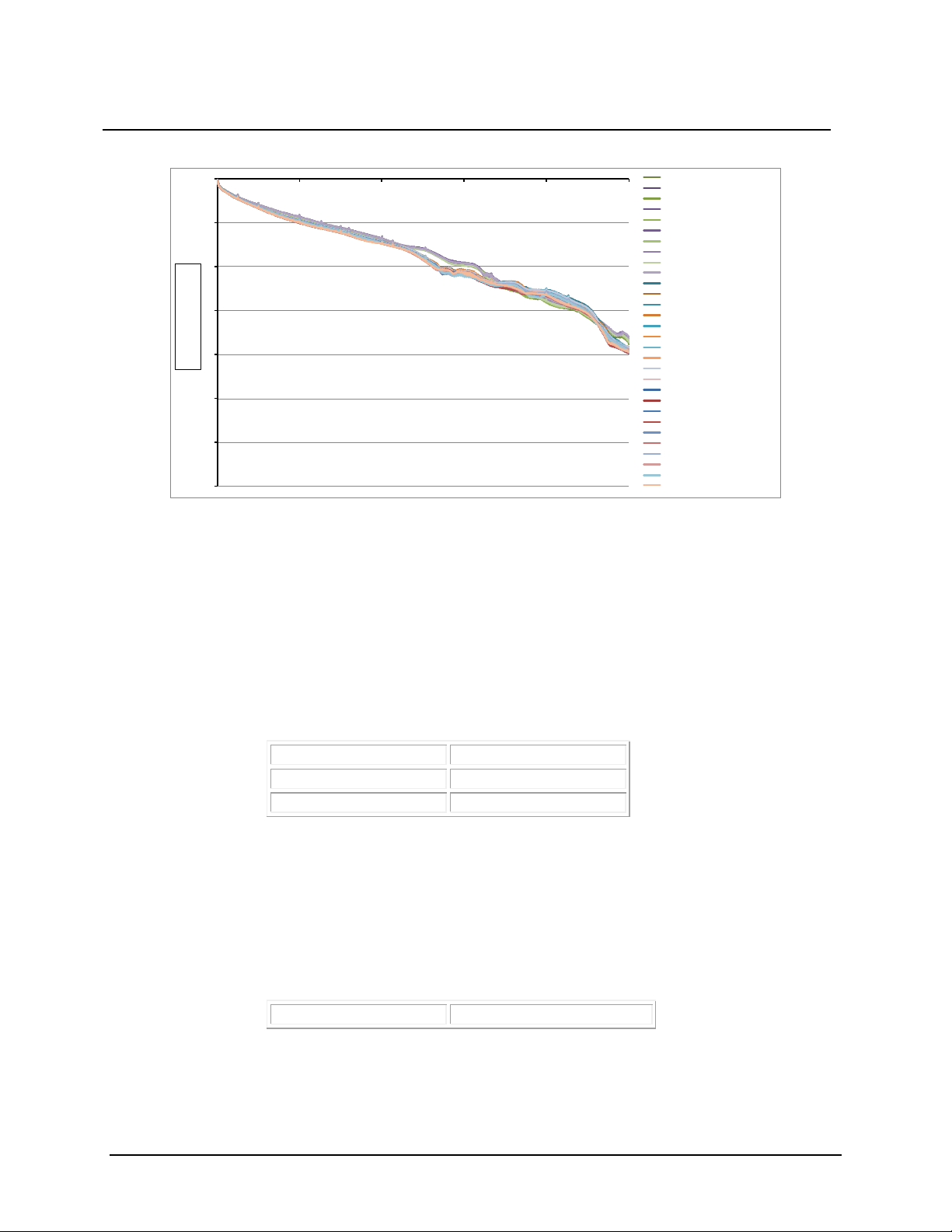
SFF 8431 Limit Line
C14_3M_Ch1_BT
C14_3M_Ch2_BT
C15_3M_Ch1_BT
C15_3M_Ch2_BT
C16_3M_Ch1_BT
C17_3M_Ch1_BT
C18_3M_Ch1_BT
C18_3M_Ch2_BT
C16_3M_Ch2_BT
C17_3M_Ch2_BT
C18_3M_Ch1_AT_30_Flex_Cycles
C18_3M_Ch2_AT_30_Flex_Cycles
C18_3M_Ch1_AT_30_Flex_Cycles
C18_3M_Ch2_AT_30_Flex_Cycles
C14_3M_Ch1_AT_30_Flex_Cycles
C14_3M_Ch2_AT_30_Flex_Cycles
C15_3M_Ch1_AT_30_Flex_Cycles
C15_3M_Ch2_AT_30_Flex_Cycles
C16_3M_Ch1_AT_30_Flex_Cycles
C16_3M_Ch2_AT_30_Flex_Cycles
C17_3M_Ch1_AT_30_Flex_Cycles
C17_3M_Ch2_AT_30_Flex_Cycles
C14_3M_Ch1_AT_Temp_Humidity_240_Hrs
C14_3M_Ch2_AT_Temp_Humidity_240_Hrs
C15_3M_Ch1_AT_Temp_Humidity_240_Hrs
C15_3M_Ch2_AT_Temp_Humidity_240_Hrs
C16_3M_Ch1_AT_Temp_Humidity_240_Hrs
C16_3M_Ch2_AT_Temp_Humidity_240_Hrs
C17_3M_Ch1_AT_Temp_Humidity_240_Hrs
C17_3M_Ch2_AT_Temp_Humidity_240_Hrs
C18_3M_Ch1_AT_Temp_Humidity_240_Hrs
C18_3M_Ch2_AT_Temp_Humidity_240_Hrs
Frequency(GHz)
Humidity — EIA-364-31
Purpose
The purpose of this test is to permit evaluation of the properties of materials used in connectors as they are
influenced or deteriorated by the effects of high humidity and heat condition.
Test Method
Mated connectors shall be tested in accordance with EIA-364-31.
Page 10
Document Number: 78-5102-0114-4 E
Issue Date: May 10, 2017
Title: Product Data Sheet
Subject: 3M™ SFP+ Direct Attach Passive Copper Cable Assembly
Page: 8 of 16
-70
-60
-50
-40
-30
-20
-10
0
0 3 6 9 12 15
C14_3M_Ch1_BT
C14_3M_Ch2_BT
C15_3M_Ch1_BT
C15_3M_Ch2_BT
C16_3M_Ch1_BT
C16_3M_Ch2_BT
C17_3M_Ch1_BT
C17_3M_Ch2_BT
C18_3M_Ch1_BT
C18_3M_Ch2_BT
C14_3M_Ch1_AT_30_Flex_Cycles
C14_3M_Ch2_AT_30_Flex_Cycles
C15_3M_Ch1_AT_30_Flex_Cycles
C15_3M_Ch2_AT_30_Flex_Cycles
C16_3M_Ch1_AT_30_Flex_Cycles
C16_3M_Ch2_AT_30_Flex_Cycles
C17_3M_Ch1_AT_30_Flex_Cycles
C17_3M_Ch2_AT_30_Flex_Cycles
C18_3M_Ch1_AT_30_Flex_Cycles
C18_3M_Ch2_AT_30_Flex_Cycles
C14_3M_Ch1_AT_Temp_Humidity_240_Hrs
C14_3M_Ch2_AT_Temp_Humidity_240_Hrs
C15_3M_Ch1_AT_Temp_Humidity_240_Hrs
C15_3M_Ch2_AT_Temp_Humidity_240_Hrs
C16_3M_Ch1_AT_Temp_Humidity_240_Hrs
C16_3M_Ch2_AT_Temp_Humidity_240_Hrs
C17_3M_Ch1_AT_Temp_Humidity_240_Hrs
C17_3M_Ch2_AT_Temp_Humidity_240_Hrs
C18_3M_Ch1_AT_Temp_Humidity_240_Hrs
C18_3M_Ch2_AT_Temp_Humidity_240_Hrs
Frequency(GHz)
Sdd
21
(dB)
Force (units):
Newtons
Mating:
18 N Max.
Unmating:
12.5N Max
Condition:
100 Cycles
5.3 Mechanical
Mating and Unmating Forces
Purpose
The purpose of this test is to determine the mechanical forces required to mate and unmate electrical connectors.
Test Method
The mechanical forces required to mate and unmate these electrical connectors.
Test Results
Durability
Purpose
The purpose of this test is to determine the effects of subjecting the cable assembly to a condition of flexing of the
cable assembly simulating operations approximating the life of the connector.
Test Method
Cable Flexing testing has been performed for 100 cycles.
Page 11
Document Number: 78-5102-0114-4 E
Issue Date: May 10, 2017
Title: Product Data Sheet
Subject: 3M™ SFP+ Direct Attach Passive Copper Cable Assembly
Page: 9 of 16
-80
-70
-60
-50
-40
-30
-20
-10
0
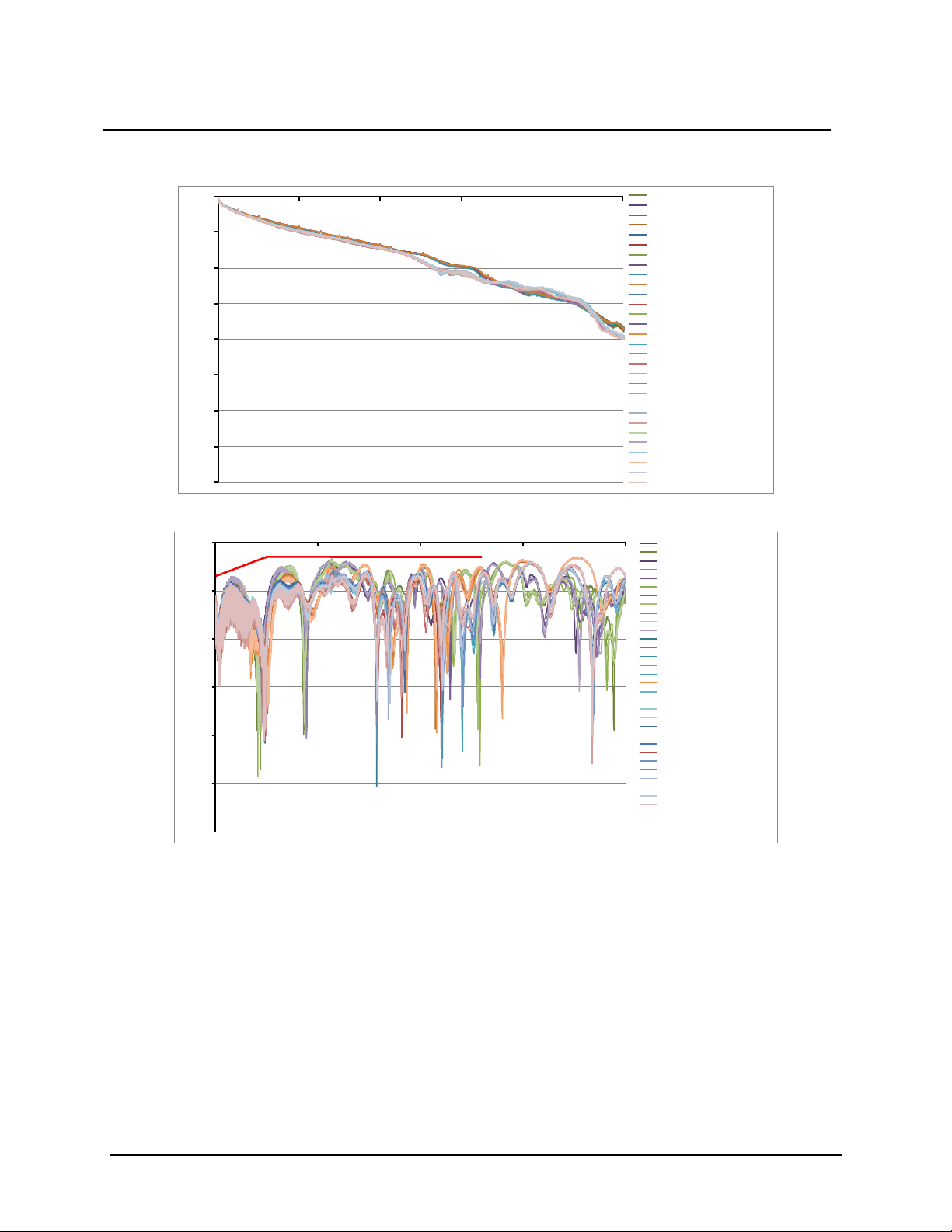
0 3 6 9 12 15
C20_3M_Ch1_BT
C20_3M_Ch2_BT
C21_3M_Ch1_BT
C21_3M_Ch2_BT
C22_3M_Ch1_BT
C22_3M_Ch2_BT
C23_3M_Ch1_BT
C23_3M_Ch2_BT
C24_3M_Ch1_BT
C24_3M_Ch2_BT
C20_3M_Ch1_AT_50_Hrs
C20_3M_Ch2_AT_50_Hrs
C21_3M_Ch1_AT_50_Hrs
C21_3M_Ch2_AT_50_Hrs
C22_3M_Ch2_AT_50_Hrs
C22_3M_Ch1_AT_50_Hrs
C23_3M_Ch1_AT_50_Hrs
C23_3M_Ch2_AT_50_Hrs
C24_3M_Ch1_AT_50_Hrs
C24_3M_Ch2_AT_50_Hrs
C20_3M_Ch1_AT_100_Flex_Cycles
C20_3M_Ch2_AT_100_Flex_Cycles
C21_3M_Ch1_AT_100_Flex_Cycles
C21_3M_Ch2_AT_100_Flex_Cycles
C22_3M_Ch1_AT_100_Flex_Cycles
C22_3M_Ch2_AT_100_Flex_Cycles
C23_3M_Ch1_AT_100_Flex_Cycles
C23_3M_Ch2_AT_100_Flex_Cycles
C24_3M_Ch1_AT_100_Flex_Cycles
C24_3M_Ch2_AT_100_Flex_Cycles
Frequency(GHz)
Sdd
21
(dB)
-60
-50
-40
-30
-20
-10
0
0 5 10 15 20
SFF 8431 Limit Line
C20_3M_Ch1_BT
C20_3M_Ch2_BT
C21_3M_Ch1_BT
C21_3M_Ch2_BT
C22_3M_Ch1_BT
C22_3M_Ch2_BT
C23_3M_Ch1_BT
C23_3M_Ch2_BT
C24_3M_Ch1_BT
C24_3M_Ch2_BT
C20_3M_Ch1_AT_50_Hrs
C20_3M_Ch2_AT_50_Hrs
C21_3M_Ch1_AT_50_Hrs
C21_3M_Ch2_AT_50_Hrs
C22_3M_Ch1_AT_50_Hrs
C22_3M_Ch2_AT_50_Hrs
C23_3M_Ch1_AT_50_Hrs
C23_3M_Ch2_AT_50_Hrs
C24_3M_Ch1_AT_50_Hrs
C24_3M_Ch2_AT_50_Hrs
C20_3M_Ch1_AT_100_F lex_Cycles
C20_3M_Ch2_AT_100_F lex_Cycles
C21_3M_Ch1_AT_100_F lex_Cycles
C21_3M_Ch2_AT_100_F lex_Cycles
C22_3M_Ch1_AT_100_F lex_Cycles
C22_3M_Ch2_AT_100_F lex_Cycles
C23_3M_Ch1_AT_100_F lex_Cycles
C23_3M_Ch2_AT_100_F lex_Cycles
C24_3M_Ch1_AT_100_F lex_Cycles
C24_3M_Ch2_AT_100_F lex_Cycles
Frequency(GHz)
Scc
11
(dB)
Test Results
Pull Tab and Mechanica l Metal Latch Pull St r e ngth
Purpose
The purpose of this test is to determine mechanical reliability of SFP+ cable assembly pull tab and mechanical latch
under differe nt pull force configuration.
Test Method
i. Pull tab axially pull with fixed load (Pull Tab, fixed at an angle 45 °) for 10 seconds
ii. Pull tab axially pull with fixed load (Pull Tab fixed at angle of 90 °) for 10 seconds
iii. Pull tab axially pull with fixed load (Pull Tab fixed vertically) for 10 seconds
Page 12
Document Number: 78-5102-0114-4 E
Issue Date: May 10, 2017
Title: Product Data Sheet
Subject: 3M™ SFP+ Direct Attach Passive Copper Cable Assembly
Page: 10 of 16
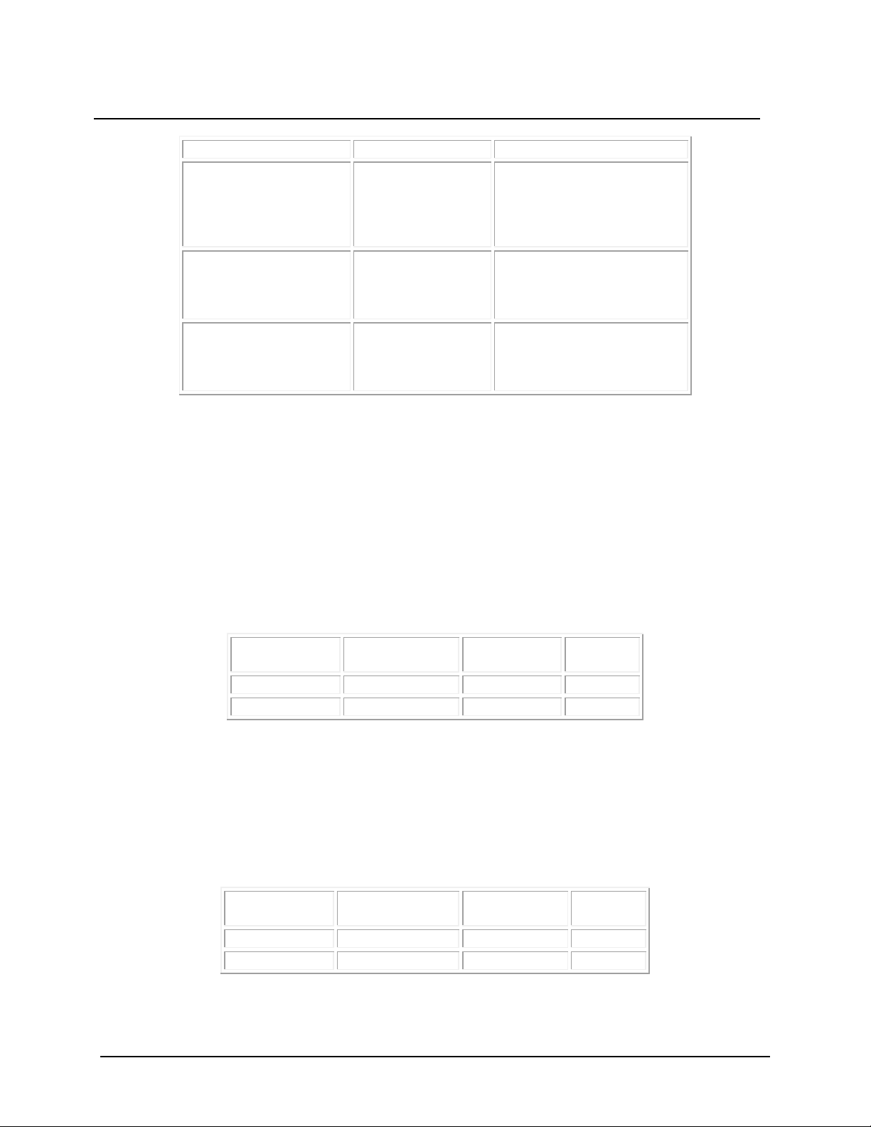
Test Category
Pull Force (N)
Observation
Pull tab axially pull with
30
No damage to the pull tab and
Pull tab axially pull with
seconds
30
No damage to the pull tab and
Pull tab axially pull with
for 10 seconds
30
No damage to the pull tab and
Cable Wire
Gauge (AWG)
Cable Length
Specification
(dB)
Results
30
3m and 5m
< 4.4
Pass
26
5m, 6m and 7m
< 4.4
Pass
Cable Wire
Gauge (AWG)
Cable Length
Specification
(dB)
Results
30
3m and 5m
> 32.5
Pass
26
5m, 6m and 7m
> 32.5
Pass
fixed load (Pull Tab, fixed
at an angle 45 °) for 10
seconds
fixed load (Pull Tab fixed
at angle of 90 °) for 10
fixed load (P ull Tab fixed
vertically)
5.4 Signal Integrity
Voltage Modulation Amplitude (VMA ) Loss — SFF 8431 Rev 4.1
Purpose
The purpose of this test is to determine the difference between the nominal one and zero level of an electrical signal
in a Passive SFP+ cable assembly.
Test Method
Voltage Modulation Amplitude (VMA) Loss is defined with square wave pattern as defined in IEEE standard 802.3.
VMA Loss of the Passive SFP+ cable assembly has been tested in accordance with standard SFF 8431 Rev4.1.
metal locking latch
metal locking latch
metal locking latch
VMA Loss to Crosstalk (VCR) Ratio — SFF 8431 Rev 4.1
Purpose
The purpose of this test is to determine the the VCR measurement is determined by computing VMA and NEXT
RMS voltage measurements in a Passive SFP+ cable assembly.
Test Method
VMA Loss to Cross Talk ratio of the Passive SFP+ cable assembly has been tested in accordance with standard SFF
8431 Rev 4.1.
Page 13
Document Number: 78-5102-0114-4 E
Issue Date: May 10, 2017
Title: Product Data Sheet
Subject: 3M™ SFP+ Direct Attach Passive Copper Cable Assembly
Page: 11 of 16
-60
-50
-40
-30
-20
-10
0
0 2
4 6 8 10 12
14 16 18 20
SFF 8431 Limit Li ne
S1_3M_Ch1
S1_3M_Ch2
S2_3M_Ch1
S2_3M_Ch2
S3_3M_Ch1
S3_3M_Ch2
S4_3M_Ch1
S4_3M_Ch2
S1_5M_Ch1
S1_5M_Ch2
S2_5M_Ch1
S2_5M_Ch2
Frequency(GHz)
Sdd
11
(dB)
-60
-50
-40
-30
-20
-10
0
0 2 4 6 8 10 12 14 16 18 20
SFF 8431 Limit Line
S1_3M_Ch1
S1_3M_Ch2
S2_3M_Ch1
S2_3M_Ch2
S3_3M_Ch1
S3_3M_Ch2
S4_3M_Ch1
S4_3M_Ch2
S1_5M_Ch1
S1_5M_Ch2
S2_5M_Ch1
S2_5M_Ch2
Frequency(GHz)
Sdd
11
(dB)
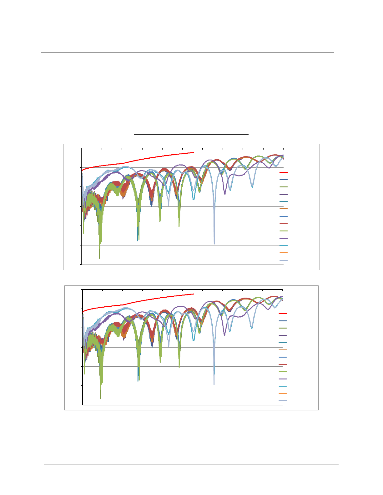
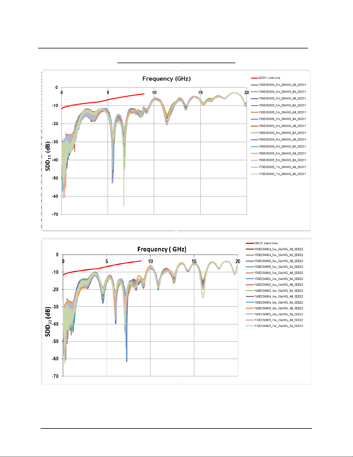
Differential Output and Input Reflection Co-efficient (SDD
and SDD22) — SFF 8431 Rev 4.1
11
Purpose
The purpose of this test is to determine the The Input and Output Reflection Co-efficient SDD
and SDD22 in a
11
Passive SFP+ cable assembly.
Test Method
Differential Output and Input Reflection Co-efficient of the Passive SFP+ cable assembly has been tested in
accordance with standard SFF 8431 Rev 4.1.
30AWG 3m and 5m Testing Results
Page 14
Document Number: 78-5102-0114-4 E
Issue Date: May 10, 2017
Title: Product Data Sheet
Subject: 3M™ SFP+ Direct Attach Passive Copper Cable Assembly
Page: 12 of 16
26AWG 5m, 6m and 7m Testing Results
Page 15
Document Number: 78-5102-0114-4 E
Issue Date: May 10, 2017
Title: Product Data Sheet
Subject: 3M™ SFP+ Direct Attach Passive Copper Cable Assembly
Page: 13 of 16
-60
-50
-40
-30
-20
-10
0
0 5 10 15 20
Scc
11
SFF 8431 Limit Li ne
S1_3M_Ch1
S1_3M_Ch2
S2_3M_Ch1
S2_3M_Ch2
S3_3M_Ch1
S3_3M_Ch2
S4_3M_Ch1
S4_3M_Ch2
S1_5M_Ch1
S1_5M_Ch2
S2_5M_Ch1
S2_5M_Ch2
Scc
11
(dB)
Frequency (GHz)
-50
-45
-40
-35
-30
-25
-20
-15
-10
-5
0
0 5 10 15 20
Scc
22
SFF 8431 Limit Li ne
S1_3M_Ch1
S1_3M_Ch2
S2_3M_Ch1
S2_3M_Ch2
S3_3M_Ch1
S3_3M_Ch2
S4_3M_Ch1
S4_3M_Ch2
S1_5M_Ch1
S1_5M_Ch2
S2_5M_Ch1
S2_5M_Ch2
Scc
22
(dB)
Frequency (GHz)
Common Mode Output and Input Reflecti on Co-efficient (SCC
and SCC22) — SFF 8431 Rev 4.1
11
Purpose
The purpose of this test is to determine the The Common Mode Reflection Co-efficient SCC
and SCC22 in a
11
Passive SFP+ cable assembly.
Test Method
Common Mode Reflection Co-efficient of the Passive SFP+ cable assembly has been tested in accordance with
standard SFF 8431 Rev 4.1.
30AWG 3m and 5m Testing Results
Page 16
Document Number: 78-5102-0114-4 E
Issue Date: May 10, 2017
Title: Product Data Sheet
Subject: 3M™ SFP+ Direct Attach Passive Copper Cable Assembly
Page: 14 of 16
26AWG 5m, 6m and 7m Testing Results
Page 17

Document Number: 78-5102-0114-4 E
Issue Date: May 10, 2017
Title: Product Data Sheet
Subject: 3M™ SFP+ Direct Attach Passive Copper Cable Assembly
Page: 15 of 16
Cable Wire
Gauge (AWG)
Cable Length
Specification
(dBe)
Results
30
3m and 5m
26
5m, 6m and 7m
Difference Wavelength Distortion Penalty (dWDP) — SFF 8431 Rev 4.1
Purpose
The purpose of this test is to determine a measure of waveform filtering and other distortion associated with the
linear optical receiver.
Test Method
Difference Wavelength Distortion Penalty (dWDP) of the Passive SFP+ cable assembly has been tested in
accordance with standard SFF 8431 Rev 4.1.
< 6.75 Pass
Page 18

Document Number: 78-5102-0114-4 E
Issue Date: May 10, 2017
Title: Product Data Sheet
Subject: 3M™ SFP+ Direct Attach Passive Copper Cable Assembly
Page: 16 of 16
Please recycle.
78-5102-0114-4 Rev E
Electronics Materials Solutions Division
www.3Mconnectors.com
3M is a trademark of 3M Company.
subsidiaries and affiliates.
UNLESS OTHERWISE NOTED, REFERENCES TO INDUSTRY SPECIFICATIONS ARE
INTENDED TO INDICATE SUBSTANTIAL COMPLIANCE TO THE MATERIAL ELEMENTS OF
THE SPECIFICATION. SUCH REFERENCES SHOULD NOT BE CONSTRUED AS A
GUARANTEE OF COMPLIANCE TO ALL REQUIREMENTS IN A GIVEN SPECIFICATION.
RoHS 2011/65/EU compliant: the product or part ("Product") does not contain any of the substances in
excess of the maximum concentration values ("MCVs") in EU Directive 2002/95/EC, as amended by
Commission Decision 2005/618/EC, and/or in the recast RoHS Directive 2011/65/EU, Annex II, unless
the substance is in an application that is exempt under the RoHS Directive 2002/95/EC, as amended,
and/or under Annex III or Annex IV to the recast RoHS Directive 2011/65/EU. The MCVs are by weight
in homogeneous materials.
In the event any product is proven not to conform with 3M’s Regulatory Information Appendix, then
3M’s entire liability and Buyer’s exclusive remedy will be in accordance with the Warranty stated below.
Regulatory: For regulatory information about this product, contact your 3M representative or visit
3M.com/regs
.
Technical Information: The technical information, recommendations and other statements contained in
this document are based upon tests or experience that 3M believes are reliable, but the accuracy or
completeness of such information is not guaranteed.
Product Use: Many factors beyond 3M’s control and uniquely within user’s control can affect the use and
performance of a 3M product in a particular application. Given the variety of factors that can affect the
use and performance of a 3M product, user is solely responsible for evaluating the 3M product and
determining whether it is fit for a particular purpose and suitable for user’s method of application.
Warranty, Limited Remedy, and Disclaimer: Unless an additional warranty is specifically stated on the
applicable 3M product packaging or product literature, 3M warrants that each 3M product meets the
applicable 3M product specification at the time 3M ships the product. 3M MAKES NO OTHER
WARRANTIES OR CONDITIONS, EXPRESS OR IMPLIED, INCLUDING, BUT NOT LIMITED TO,
ANY IMPLIED WARRANTY OR CONDITION OF MERCHANTABILITY OR FITNESS FOR A
PARTICULAR PURPOSE OR ANY IMPLIED WARRANTY OR CONDITION ARISING OUT OF A
COURSE OF DEALING, CUSTOM OR USAGE OR TRADE. If the 3M product does not conform to
this warranty, then the sole and exclusive remedy is, at 3M’s option, replacement of the 3M product or
refund of the purchase price.
Limitation of Liability: Except where prohibited by law, 3M will not be liable for any loss or damage
arising from the 3M product, whether direct, indirect, special, incidental or consequential, regardless of
the legal theory asserted, including warranty, contract, negligence or strict liability.
Interconnect Products
6801 River Place Blvd.
Austin, TX 78726-9000
Issued 05/17
©3M 2017.
All rights reserved.
Used under license by 3M
 Loading...