

Page 1
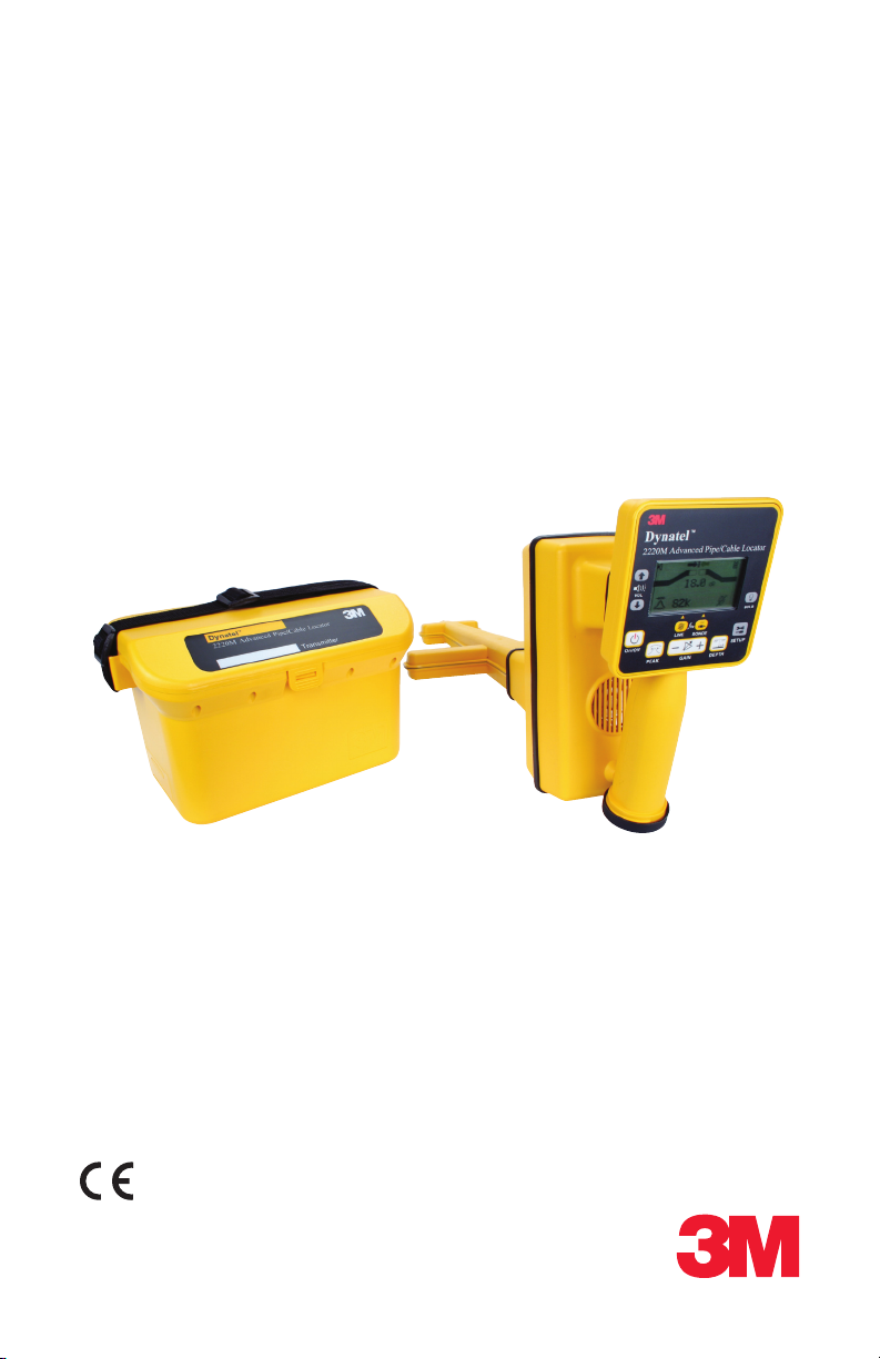
3M™ Dynatel™
Advanced Pipe/Cable Locator 2220M
Operator Manual
78-9000-0021-3-A
December 2007
Page 2

Contents
Introduction .........................................................................................1
™
Standard 3M
Dynatel™ 2220M Locator Equipment Packages ..2
Optional 3M Dynatel Accessories
Quick Start
Transmitter Battery Installation
Transmitter Overview
Receiver Battery Installation
Receiver Overview
Transmitter Operations
Direct Connection
3M Dynatel Dyna-Coupler Clamp
Induction Method
Receiver Operations
Initial Settings
Receiver Setup
Line Locating Screen
Pipe and Cable Locating
...........................................................................................3
....................................................................3
........................................................................5
........................................................................6
.........................................................................6
..........................................................................7
............................................................................8
................................................................................8
...............................................................................8
..................................................................11
.............................................................12
................................................2
....................................................3
.........................................................4
...............................................6
Depth and Current
Sonde Locating
Sonde Locating Screen
Pin-Pointing the Sonde
Specifications .....................................................................................15
CE Compliance
Statement of Conformity
Statement of Intended Use
..................................................................................17
.......................................................................12
............................................................................13
................................................................13
................................................................14
.............................................................17
..........................................................17
Page 3
Introduction
Congratulations! You have just purchased one of the finest, most advanced
locating devices available today! When you choose a quality 3M™ Dynatel™
Advanced Pipe/Cable Locator 2220M, you get outstanding performance and
reliability.
The 2220M locator is an excellent instrument for tracing all underground
utilities. The 2220M provides one audio frequency for locating long sections of
cable and one radio frequency for tracing pipes that may have high resistance
insulators and rubber gaskets that are often found in water and gas distribution
systems. The 2220M also provides three sonde locating frequencies.
1
Page 4

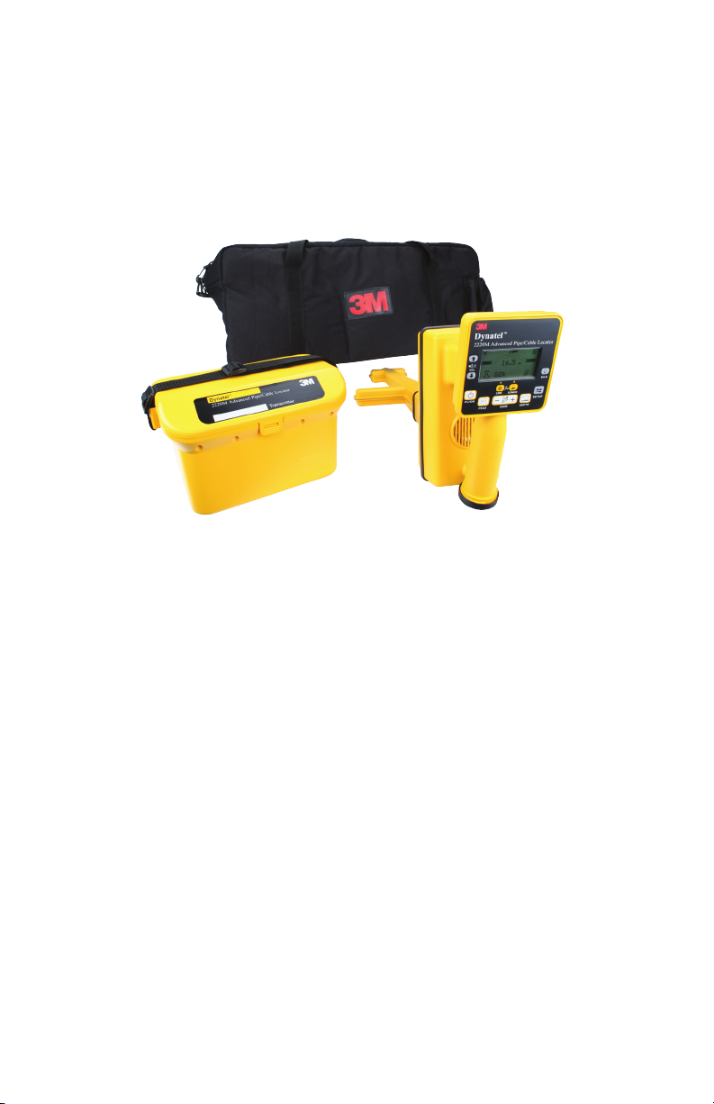
Standard 3M™ Dynatel™ 2220M Locator
Equipment Packages
Model Number Included in Equipment Package
2220M-U3W
2220M-U3W-CPLR
2220M-C3W-CPLR
2220M Receiver
3 Watt Transmitter
Direct Connect Cable (Utility size clip 5/8")
Ground Rod
Operator Manual
Carrying Bag
2220M Receiver
3 Watt Transmitter
Direct Connect Cable (Utility size clip 5/8")
4.5" (114 mm) Dyna-Coupler clamp
Coupler Cable
Ground Rod
Operator Manual
Carrying Bag
2220M Receiver
3 Watt Transmitter
Direct Connect Cable (Telecom size clip ¼")
3" (76 mm) Dyna-Coupler clamp
Coupler Cable
Ground Rod
Operator Manual
Carrying Bag
Optional 3M Dynatel Accessories
3" (76 mm) Dyna-Coupler Clamp 3001
•
4.5" (114 mm) Dyna-Coupler Clamp 4001
•
6" (150 mm) Dyna-Coupler Clamp 1196
•
Coupler Cable 9011
•
Direct Connect Leads (Small Telecom clips) 2892
•
Ground Extension Cable 9043
•
2
Page 5
Quick Start
Dynatel™ 220M
Off On
Frequency
Output Level
Hz
ƒ
Induction Direction
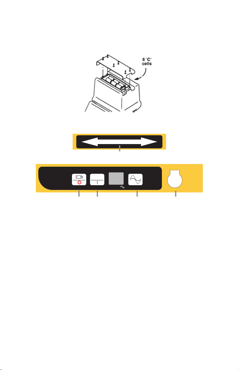
Transmitter Battery Installation
Transmitter Overview
➎
➊ ➋
1. Power OFF / Battery Level Indicator – Press and hold.
Display reads:
“OK” with solid tone = good
“LO” with pulsing tone = low
“- -” with no tone = replace
2. Power ON / Frequency Select – Powers on the unit. When pressed
repeatedly, it will cycle through the available frequency modes:
a. Single audio frequency - 8 kHz
b. Single radio frequency - 82 kHz
c. Dual frequency – Both 8 kHz and 82 kHz are transmitted
simultaneously.
3. Output Level – Toggles the output power level between Normal output and
High output. Flag will flash over output icon on display when in High output
mode.
4. Output Jack – Direct Connect and 3M™ Dynatel™ Dyna-Coupler Clamp port.
5. Induction Direction Arrows – Indicates orientation of transmitter in
relationship to target path.
➌ ➍
3
Page 6
Warning
Potential for electric shock exists when handling connection cables while the
transmitter is ON. Make all connections prior to powering on the unit. Turn the
transmitter OFF before handling connection cables.
Warning
Voltage greater then 240 volts will damage equipment and could cause personal
injury or death. Make all connections before turning on the transmitter. Follow
standard procedures for reducing the voltage.
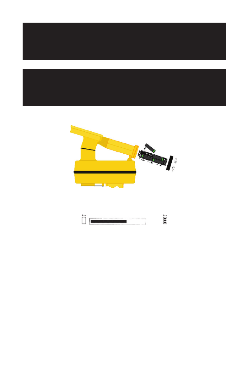
Receiver Battery Installation
The Receiver displays the battery level across the bottom of the start up screen
when the unit is powered on.
4
Page 7

Receiver Overview
➊
➍ ➎
➋
➌
1. Volume Control – Adjusts the volume of the receiver through three levels of
audio and off.
2. Power Key – Powers the receiver on and off.
3. Peak Key – Toggles between Directional Peak and Single Peak antenna
configuration.
4. Line Locate Key – Places the Receiver in Pipe/Cable locating mode and
selects frequency. When toggled, it will cycle between 8 kHz, 82 kHz, and
60 Hz (Power Mode). (More frequencies are available in setup mode).
5. Sonde Locate Key – Places the receiver in sonde locate mode and selects
sonde frequency. When toggled, it will cycle between 512 Hz and 33 kHz.
More frequencies are available in setup mode.
6. Gain Adjust – Adjusts the sensitivity of the receiver either up (+) or down
(-) to maintain a satisfactory audio and bar graph response.
7. Depth Key – Displays depth to target pipe/cable/sonde.
8. Setup Key – Configure receiver depth units, enable/disable line and sonde
frequencies, select 50/60 Hz power frequencies.
9. Bulb Key – Turns the display backlight on and off.
➏ ➐
➒
➑
5
Page 8

Transmitter Operations
There are three different methods of applying the transmitter’s locating signal to
the target conductor: Direct Connection, 3M™ Dynatel™ Dyna-Coupler Clamp,
and Induction.
Direct Connection
This is the preferred mode of operation because the transmitter is connected
directly to a metallic portion of the target conductor (hydrant, meter, riser,
valve, sheath, or tracer wire).
1. While the transmitter is off, plug the direct connect cable into the output
jack of the transmitter.
2. Attach the red lead of the direct connect cable to the target conductor.
3. Extend the black lead as far as possible from the target conductor at a right
angle (90 degrees) to the suspected path of the target.
4. Insert the external ground rod and attach the black lead of the transmitter.
5. Turn the transmitter ON by pressing the frequency button. Select 8 kHz,
82 kHz, or both (8 K and 82 K will flash on the display).
6. An audible tone, indicating the continuity of the signal path will sound for
10 seconds and the output current will display in mA.
a. Solid tone = Good signal
b. Fast Beep = Moderate signal
c. Slow Beep = Minimal signal
d. No tone = Poor signal
7. The frequency will flash alternately with the current of the target conductor
on the display.
8. Trace the signal path with the receiver. (See Receiver Operations, page 8.)
3M Dynatel Dyna-Coupler Clamp
If a direct connection to the target facility is not possible, use the Dyna-Coupler
clamp to apply the locating frequency on the metallic target conductor. In order
to trace a target using the Dyna-coupler method, both ends of the target must be
well grounded.
1. While the transmitter is off, attach the coupler cable to the Dyna-Coupler
clamp and plug it into the output jack of the transmitter.
2. Clamp the Dyna-coupler around the metallic target. The jaws of the coupler
must be fully closed.
3. Select 8 kHz or 82 kHz on the transmitter by pressing the frequency key.
4. Select High Output level for the best signal-to-noise ratio.
5. Trace the signal path with the receiver. (See Receiver Operations, page 8.)
6
Page 9

Induction Method
If you cannot make a direct connection, or use the 3M™ Dynatel™ Dyna-Coupler
clamp to apply a locating signal on the target, use the induction method. This
method uses the internal coil of the transmitter to generate a magnetic field.
This is the least preferred method of applying a signal on a target conductor
because it can easily be picked up by other non-target conductors in the area.
However, it is the preferred method of applying a signal to multiple cables/pipes
in the same trench.
1. Verify battery level of transmitter and remove any cables from the output
jack.
2. Position the transmitter over the target facility, with the hinge of the
transmitter over and in line with the cable/pipe path.
3. Align the Induction Direction arrows on the transmitter with the target
conductor.
4. Turn on the transmitter by pressing the frequency key.
5. Select High Output level for the best signal-to-noise ratio.
Note: If nothing is plugged into the output jack of the transmitter, the
transmitter will automatically turn on the internal antennae, and 82 kHz
will broadcast in induction mode. For best results, the receiver should be
at least 40 feet (12 m) away from the transmitter to begin tracing the target
path. Attempting to trace the target close to the transmitter may lead to false
indications due to the receiver detecting the large magnetic field radiating
from the transmitter.
7
Page 10

Receiver Operations
Initial Settings
From the manufacturing facility, the receiver is configured as follows:
Line Locate Frequencies Selection Default
8 kHz Always Enabled Enabled
82 kHz
Power Always Enabled Enabled
Radio Enable/Disable Disabled
CATV Enable/Disable Disabled
CPS Enable/Disable Disabled
Sonde Locate Frequencies
512 Hz Enable/Disable Enabled
640 Hz Enable/Disable Disabled
33 kHz Enable/Disable Enabled
Units inch or cm Inch
Power Frequency 50 Hz or 60 Hz 60 Hz
Contrast Up or Down Middle
Depth Measurement Live or One-Shot One-Shot
The setup function will allow you to enable or disable additional locating and
sonde frequencies.
Always Enabled Enabled
Receiver Setup
Any of the available frequencies of the 3M™ Dynatel™ Advanced Pipe/Cable
Locator 2220M can be activated or deactivated. When a frequency is activated,
a check mark will appear beside the frequency in the middle of the setup screen.
All frequencies that are activated in the setup menu, will be available in the
locate screens.
When the Setup key is pressed, the receiver will cycle through the following
screens.
Select the left/right arrow keys (← →) to cycle through the setup screens.
Contrast Adjust
Press the up or down arrows ( or ) to
adjust the screen contrast.
8
Page 11

512 Hz – Sonde frequency indicated by
sonde icon.
Press the down key to enable/disable
the frequency. A check mark will
appear in the box when the frequency is
enabled.
640 Hz - Sonde frequency indicated by
sonde icon.
Press the down key to enable/disable
the frequency. A check mark will
appear in the box when the frequency is
enabled.
33 kHz - Sonde frequency indicated by
sonde icon.
Press the down key to enable/disable
the frequency. A check mark will
appear in the box when the frequency is
enabled.
Radio or LF - Low Frequency Band:
15 Khz–30 kHz
Press the down key to enable/disable
the frequency. A check mark will
appear in the box when the frequency is
enabled.
CATV – 31.5 kHz
Press the down key to enable/disable
the frequency. A check mark will
appear in the box when the frequency is
enabled.
9
Page 12

CPS – Cathodic Protection System–
120 Hz or 100 Hz (based on 60/50 Hz
selection)
Press the down key to enable/disable
the frequency. A check mark will
appear in the box when the frequency is
enabled.
50 Hz / 60 Hz
To change the power frequency
selection, press the up (60) or down
(50) key. The selected frequency will
appear in the box at the center of the
screen.
Snapshot/Continuous Depth Modes
Continuous depth measurements can
be displayed on the screen in live mode
or the depth can be frozen in snapshot
mode.
Press the down key to enable/disable
snapshot depth mode. A check mark
will appear in the box when snapshot is
enabled.
Depth Units
Select the up (inch) or down (cm) key
to select the preferred units of measure.
The selection will appear in the box at
the center of the screen.
Information
This screen provides important
information including the product serial
number, as well as the software and
hardware versions of the unit.
10
Page 13

Line Locating Screen
➐
➊
➏
➋
➌
1. Speaker Icon – Indicates audio level
2. Bar graph – Graphical representation of received signal
3. Peak Mode Indicator – Indicates single or directional peak mode
4. Selected Line Locating Frequency – Displays the frequency the receiver
will detect
5. Line Locating Icon – Indicates line locating mode vs. sonde mode
6. Battery Icon – Indicates battery level of receiver
7. Directional Arrows – Left/right indicators for path tracing
8. Signal Level – Numerical reading of received signal (dB)
➍ ➎
➑
11
Page 14

Pipe and Cable Locating
1. Press the on/off key.
2. Press the line key to match the frequency that the transmitter is sending.
3. Sweep the receiver across the area in a left right motion, while watching the
bar graph, directional arrows, and signal strength.
4. When a magnetic field is detected, the bar graph will close, the signal
strength and the audio will increase.
5. Adjust the gain so that the bar graph opens when the receiver is not on target
and closes when directly over it by pressing the + or – gain key.
6. Pinpoint the target by moving the receiver left and right over the magnetic
field until both arrows appear.
7. Place the tip of the receiver on the ground over the target path and measure
depth of the conductor by pressing the Depth key.
8. Verify the depth of the target is as expected, and the current is comparable
with the current displayed on the transmitter.
Depth and Current
To measure the depth of a target, place
the tip of the receiver on the ground.
Press the Depth key.
The depth to the target conductor and
the current will display for five seconds.
Refer to receiver set up section to select
“snapshot” of “live” depth modes.
Note: To further verify target, this current reading can be compared to the
current reading on the transmitter.
12
Page 15

Sonde Locating
A sonde is a small transmitter that enables the user to trace metallic and
nonmetallic pipes, sewers, drains, or ducts. It can also be used to find a blockage
or collapse. Refer to sonde manufacturer’s guide for proper selection of sonde
for the desired application.
A representation of a sonde transmission field appears below.
There are typically three peak signals present. The strongest peak signal is over
the center of the sonde. The signal will drop off each ‘side’ or ‘end’ of the sonde,
and then rise again. The ‘drop off points’ are referred to as nulls.
Sonde Locating Screen
➊
➏
➋
➌ ➍ ➎
1. Speaker Icon – Indicates audio level
2. Bar graph – Graphical representation of received signal
3. Antennae Icon – Indicates single peak mode
4. Selected Sonde Frequency – Toggles through activated sonde frequencies
(512, 640, or 33 k)
5. Sonde Icon – Indicates sonde mode vs. line locating
6. Battery Icon – Indicates battery level of receiver
7. Signal Level – Numerical reading of received signal (dB)
➐
13
Page 16

Pin-Pointing the Sonde
Note: The receiver handle must be oriented perpendicular to the sonde. The
cross bar of the receiver must be in line with the sonde (the opposite of line
locating).
1. Set the receiver to Sonde mode by pressing the Sonde key until the
frequency of the sonde appears on the locate screen.
2. Holding the receiver perpendicular to the suspected path, walk the path until
the receiver detects the first peak signal of the sonde.
3. Adjust the gain down if the bar graph closes completely.
4. Continue to walk the path. Observe the response of the receiver as the center
(and strongest) peak of the sonde’s magnetic field is detected.
5. Continue past this strong peak. The signal will fall and then rise again as the
last weak peak is detected.
6. Retrace your steps, watching the receiver.
7. The sonde has been pinpointed when the center of the strongest peak has
been found.
8. Measure the depth of the sonde by placing the tip of the receiver on the
ground and pressing the depth key. Refer to receiver set up section to select
“snapshot” of “live” depth modes.
14
Page 17

Specifications
Receiver
Locating Modes Special (Single) Peak, Dual Peak w/Direction, Depth & Current
Gain Adjustment Automatic with Manual override
Frequencies
Active
Passive Power
Passive LF
Passive CATV
Cathodic Protection
Auxiliary/Sonde (Receive only)
Display Resolution 0.1 dB
Depth Display Range 0–30 ft (9 m)
Depth Units cm, inch & ft-in
Depth Accuracy **
Cable Current Display
Battery type 8 AA size, Alkaline
Typical Battery Life 30 hrs
Display Large Graphic high contrast LCD w/ backlight
Speaker 0.25 W
Headphone Jack Standard Mini Jack
Serial Port Standard RS232 serial w/DB9 connector
* American NTSC, television set on
** Locators are tested in model field conditions with no adjacent signals. Actual operating conditions
may result in decreased depth accuracy due to outside signal disruptions.
8 kHz, 82 kHz
50 Hz or 60 Hz
VLF 15 k – 30 kHz
31.5 kHz *
100 Hz or 120 Hz
512 Hz, 640 Hz, 33 kHz
± 2% ± 3 in (5 cm) 0–60 in (1.5 m)
± 6% ± 3 in (5 cm) 61–120 in (1.5 m–3 m)
± 10% ± 3 in (5 cm) 121–180 in (3–4.5 m)
0.01 mA resolution
Units: mA
Transmitter
Output Frequencies
Trace Mode
Induction mode
Output voltage (max)
Trace
Output Power
Output Protection 240 Vrms
Battery type 6 C size, Alkaline (LR14)
Typical Battery Life
8 kHz, 82 kHz
82 kHz
60 Vrms
Normal setting: 0.5 W
High setting: 3 W @ 8 kHz, 1 W @ 82 kHz
Normal output level: 45 hrs
High output level: 7 hrs
15
Page 18

Environmental
Operating Temperature –4° F to 122° F (–20° to 50° C)
Storage Temperature –4° F to 158° F (–20° to 70° C)
Standard IP54
Regulatory CE
Physical Specification
Size (H x W x D) in (cm) Weight (w/ batteries)
Transmitter
Receiver
Shipping N/A 17 lb (7.9 kg)
6.75 x 11.25 x 7.75
(17.2 x 28.6 x 19.7)
10.25 x 10.5 x 30
(26.7 x 26.1 x 76.2)
5.2 lb
(2.4 kg)
4.05 lb
(1.9 kg)
Cleaning Instructions
Use a soft damp cloth to clean the product and test leads if necessary.
16
Page 19

CE Compliance
Statement of Conformity
“Hereby, 3M declares that this Underground Locating Product is in compliance
with the essential requirements and other relevant provisions of Directive
1999/5/EC.”
www.3m.com/market/telecom/access/conformity/
Statement of Intended Use
The 3M™ Dynatel™ Advanced Pipe/Cable Locator 2220M models are designed
and tested for use in locating buried cables, pipes, utilities and structures. These
products have not been tested or proven safe for other uses. The use of these
products may be subject to licensing restrictions.
17
Page 20

This product is in accordance with the requirements
This is the EU symbol for equipment that is covered
under the Waste from Electrical and Electronic
Equipment (WEEE) directive per CENELEC
Specification 5041. It indicates that certain products
should not be discarded in the trash, but rather
should be recycled. This applies to all electronic
pluggable and battery powered products.
of the European directive 99/5/EC.
3M and Dynatel are trademarks of 3M Company.
Important Notice
All statements, technical information, and recommendations related to 3M’s products are based on information
believed to be reliable, but the accuracy or completeness is not guaranteed. Before using this product, you must
evaluate it and determine if it is suitable for your intended application. You assume all risks and liability associated
with such use. Any statements related to the product which are not contained in 3M’s current publications, or
any contrary statements contained on your purchase order shall have no force or effect unless expressly agreed
upon, in writing, by an authorized officer of 3M.
Warranty; Limited Remedy; Limited Liability.
This product will be free from defects in material and manufacture for a period of one (1) year from the time
of purchase. 3M MAKES NO OTHER WARRANTIES INCLUDING, BUT NOT LIMITED TO, ANY IMPLIED
WARRANTY OF MERCHANTABILITY OR FITNESS FOR A PARTICULAR PURPOSE. If this product is defective
within the warranty period stated above, your exclusive remedy shall be, at 3M’s option, to replace or repair the
3M product or refund the purchase price of the 3M product. Except where prohibited by law, 3M will not
be liable for any indirect, special, incidental or consequential loss or damage arising from this 3M
product, regardless of the legal theory asserted.
3
Track and Trace Solutions
6801 River Place Blvd.
Austin, TX 78726-9000
1-800-462-8688
www.3M.com/dynatel
Please Recycle. Printed in USA.
© 3M 2007. All Rights Reserved.
78-9000-0021-3-A
 Loading...