

Page 1
S
UPERSTACK
®
A
DMINISTRATION
U
SER
G
UIDE
™
II S
WITCH
C
ONSOLE
2200
Part No. 801-00310-000
Published September 1996
Revision 01
Page 2

3Com Corporation ■ 5400 Bayfront Plaza ■ Santa Clara, California ■ 95052-8145
© 3Com Corporation, 1996. All rights reserved. No part of this documentation may be reproduced in any form or by any means or used to make
any derivative work (such as translation, transformation, or adaptation) without permission from 3Com Corporation.
3Com Corporation reserves the right to revise this documentation and to make changes in content from time to time without obligation on the
part of 3Com Corporation to provide notification of such revision or change.
3Com Corporation provides this documentation without warranty of any kind, either implied or expressed, including, but not limited to, the
implied warranties of merchantability and fitness for a particular purpose. 3Com may make improvements or changes in the product(s) and/or
the program(s) described in this documentation at any time.
UNITED STATES GOVERNMENT LEGENDS:
If you are a United States government agency, then this documentation and the software described herein are provided to you subject to the
following restricted rights:
For units of the Department of Defense:
Restricted Rights Legend:
restricted Rights in Technical Data and Computer Software clause at 48 C.F.R. 52.227-7013. 3Com Corporation, 5400 Bayfront Plaza, Santa Clara,
California 95052-8145.
For civilian agencies:
Restricted Rights Legend: Use, reproduction, or disclosure is subject to restrictions set forth in subparagraph (a) through (d) of the Commercial
Computer Software - Restricted Rights Clause at 48 C.F.R. 52.227-19 and the limitations set forth in 3Com Corporation’s standard commercial
agreement for the software. Unpublished rights reserved under the copyright laws of the United States.
If there is any software on removable media described in this documentation, it is furnished under a license agreement included with the
product as a separate document, in the hardcopy documentation, or on the removable media in a directory file named LICENSE.TXT. If you are
unable to locate a copy, please contact 3Com and a copy will be provided to you.
Unless otherwise indicated, 3Com registered trademarks are registered in the United States and may or may not be registered in other countries.
3Com, LANplex, LinkBuilder, NETBuilder, NETBuilder II, ViewBuilder, EtherDisk, EtherLink, EtherLink II, and Transcend are registered trademarks of
3Com Corporation. 3TECH, FDDILink, SmartAgent, and Star-Tek are trademarks of 3Com Corporation. 3ComFacts is a service mark of 3Com
Corporation.
IBM and Netview AIX are registered trademarks of International Business Machines Corporation. Apple, AppleTalk, and Macintosh are trademarks
of Apple Computer, Inc. CompuServe is a registered trademark of CompuServe, Inc. MS-DOS and Windows are registered trademarks of
Microsoft Corporation. OpenView is a registered trademark of Hewlett-Packard Co. Sniffer is a registered trademark of Network General Corp.
SunNet Manager, SunOS, and OpenWindows are trademarks of Sun Microsystems, Inc. UNIX is a registered trademark of Novell Inc.
Other brand and product names may be registered trademarks or trademarks of their respective holders.
Guide written, edited, and illustrated by Beth Britt, Patricia Crawford, Lynne Gelfand, Michael Jenness, Patricia L. Johnson, Michael Taillon, and
Iain Young. Edited by Bonnie Jo Collins.
Use, duplication, or disclosure by the Government is subject to restrictions as set forth in subparagraph (c) (1) (ii) for
Page 3

P
ART
C
ONTENTS
A
BOUT THIS GUIDE
Introduction 1
How to Use This Guide 2
Conventions 3
Switch 2200 Documentation 4
Documentation Comments 5
II
1
2
NTRODUCTION
S
UPERSTACK
About Switch 2200 Administration 1-1
Configuration Tasks 1-1
HOW TO USE
Initial User Access 2-1
Levels of User Access 2-1
Administer Access Example 2-2
Write Access Example 2-2
Read Access Example 2-3
Using Menus to Perform Tasks 2-3
Administration Console Menu Structure 2-4
System Menu 2-4
Ethernet Menu 2-4
FDDI Menu 2-5
Bridge Menu 2-5
IP Menu 2-6
SNMP Menu 2-7
Analyzer Menu 2-7
Selecting Menu Options 2-8
Entering Values 2-9
Getting Out 2-9
™ II S
THE ADMINISTRATION CONSOLE
WITCH
2200 A
DMINISTRATION OVERVIEW
Page 4

P
ART
Administration Console Interface Parameters 2-10
Remote Access Parameters 2-11
Running Scripts of Administration Console Tasks 2-13
Getting Help in the Administration Console 2-16
Exiting the Administration Console 2-17
II S
3
C
About Management Access 3-1
Setting Up the Console Serial Port 3-2
Setting Up an IP Interface for Management 3-3
Adjusting the Screen Height 2-10
Disabling the Reboot and Abort Keys 2-11
Preventing Disconnections 2-11
Enabling Timeout of Remote Sessions 2-12
Setting Timeout Interval for Remote Sessions 2-13
Online Help 2-16
Viewing More Levels of Menu Options 2-16
YSTEM-LEVEL FUNCTIONS
ONFIGURING MANAGEMENT ACCESS TO THE SYSTEM
Using a Serial Connection 3-1
Using an IP Interface 3-1
In-band or Out-of-band? 3-2
General Setup Process 3-3
Administering Interfaces 3-3
Displaying Interfaces 3-4
Defining an Interface 3-5
Modifying an Interface 3-6
Removing an Interface 3-7
Administering Routes 3-7
Displaying the Routing Table 3-8
Defining a Static Route 3-9
Removing a Route 3-9
Flushing a Route 3-10
Setting the Default Route 3-10
Removing the Default Route 3-10
Administering the ARP Cache 3-11
Displaying the ARP Cache 3-11
Removing an ARP Cache Entry 3-11
Flushing ARP Cache Entries 3-12
Setting the RIP Mode 3-12
Pinging an IP Station 3-12
Displaying IP Statistics 3-14
Page 5

Setting Up SNMP on Your System 3-15
Displaying SNMP Settings 3-15
Configuring Community Strings 3-15
Administering SNMP Trap Reporting 3-16
Displaying Trap Information 3-16
Configuring Trap Reporting 3-17
Removing Trap Destinations 3-18
Flushing Trap Destinations 3-19
Setting Up SMT Event Proxying 3-19
4
A
DMINISTERING YOUR SYSTEM ENVIRONMENT
Displaying the System Configuration 4-1
Setting Passwords 4-2
Setting the System Name 4-3
Changing the Date and Time 4-3
Rebooting the System 4-4
5
B
ASELINING STATISTICS
About Setting Baselines 5-1
Displaying the Current Baseline 5-1
Setting Baselines 5-2
Enabling or Disabling Baselines 5-2
P
ART
6
S
About Working with Nonvolatile Data 6-1
Saving NV Data 6-2
Restoring NV Data 6-3
Examining a Saved NV Data File 6-5
Resetting NV Data to Defaults 6-6
III E
7
A
Displaying Ethernet Port Information 7-1
Labeling a Port 7-8
Setting the Port State 7-8
AVING
THERNET AND
DMINISTERING ETHERNET PORTS
, R
ESTORING, AND RESETTING NONVOLATILE DATA
FDDI P
ARAMETERS
Page 6

8
A
DMINISTERING
Administering FDDI Stations 8-1
Displaying Station Information 8-2
Setting the Connection Policies 8-3
Setting Neighbor Notification Timer 8-5
Enabling and Disabling Status Reporting 8-5
Administering FDDI Paths 8-6
Displaying Path Information 8-6
Setting tvxLowerBound 8-7
Setting tmaxLowerBound 8-8
Setting maxT-Req 8-9
Administering FDDI MACs 8-9
Displaying MAC Information 8-10
Setting the Frame Error Threshold 8-16
Setting the Not Copied Threshold 8-17
Enabling and Disabling LLC Service 8-18
Setting the MAC Paths 8-18
Administering FDDI Ports 8-19
Displaying Port Information 8-19
Setting lerAlarm 8-20
Setting lerCutoff 8-21
Setting Port Labels 8-22
Setting the Port Paths 8-23
FDDI R
ESOURCES
P
ART
9
S
About Roving Analysis 9-1
Displaying the Roving Analysis Configuration 9-2
Adding an Analyzer Port 9-3
Removing an Analyzer Port 9-4
Starting Port Monitoring 9-5
Stopping Port Monitoring 9-6
IV B
10
A
Displaying Bridge Information 10-1
Enabling and Disabling IP Fragmentation 10-5
Enabling and Disabling IPX Snap Translation 10-5
Setting the Address Threshold 10-6
Setting the Aging Time 10-6
ETTING UP THE SYSTEM FOR ROVING ANALYSIS
RIDGING PARAMETERS
DMINISTERING THE BRIDGE
Page 7

Administering STP Bridge Parameters 10-7
Enabling and Disabling STP on a Bridge 10-7
Setting the Bridge Priority 10-7
Setting the Bridge Maximum Age 10-8
Setting the Bridge Hello Time 10-9
Setting the Bridge Forward Delay 10-9
Setting the STP Group Address 10-10
11
12
A
DMINISTERING BRIDGE PORTS
Displaying Bridge Port Information 11-1
Setting the Multicast Limit 11-7
Administering STP Bridge Port Parameters 11-8
Enabling and Disabling STP on a Port 11-8
Setting the Port Path Cost 11-9
Setting the Port Priority 11-10
Administering Port Addresses 11-11
Listing Addresses 11-11
Adding New Addresses 11-12
Removing Addresses 11-12
Flushing All Addresses 11-13
Flushing Dynamic Addresses 11-13
Freezing Dynamic Addresses 11-13
C
REATING AND USING PACKET FILTERS
About Packet Filtering 12-1
Listing Packet Filters 12-2
Displaying Packet Filters 12-3
Creating Packet Filters 12-3
Concepts for Writing a Filter 12-4
How the Packet Filter Language Works 12-4
Basic Elements of a Packet Filter 12-6
Implementing Sequential Tests in a Packet Filter 12-8
Preprocessed and Run-time Storage 12-9
Procedure for Writing a Filter 12-10
Examples of Creating Filters 12-11
Filtering Problem 12-11
Packet Filter Solution 12-12
Tools for Writing a Filter 12-17
Using the Built-in Line Editor 12-17
Using an External Text Editor 12-20
Deleting Packet Filters 12-20
Editing, Checking and Saving Packet Filters 12-20
Page 8

Loading Packet Filters 12-22
Assigning Packet Filters to Ports 12-22
Unassigning Packet Filters from Ports 12-24
13
C
ONFIGURING ADDRESS AND PORT GROUPS TO
ACKET FILTERS
P
Using Groups in Packet Filters 13-1
Listing Groups 13-2
Displaying Groups 13-3
Creating New Groups 13-4
Deleting Groups 13-6
Adding Addresses and Ports to Groups 13-7
Removing Addresses or Ports from a Group 13-9
Loading Groups 13-11
USE IN
PART APPENDIXES
A PACKET FILTER OPCODES, EXAMPLES, AND SYNTAX ERRORS
Opcodes A-1
Packet Filter Examples A-9
Destination Address Filter A-9
Source Address Filter A-9
Length Filter A-9
Type Filter A-10
Ethernet Type IPX and Multicast Filter A-10
Multiple Destination Address Filter A-10
Source Address and Type Filter A-11
Accept XNS or IP Filter A-11
XNS Routing Filter A-11
Address Group Filter A-12
Port Group Filter A-12
Common Syntax Errors A-13
Page 9

B TECHNICAL SUPPORT
Online Technical Services B-1
3Com Bulletin Board Service B-1
Access by Modem B-1
Access by ISDN B-2
World Wide Web Site B-2
3ComForum on CompuServe® B-2
3ComFactsSM Automated Fax Service B-3
Support from Your Network Supplier B-3
Support from 3Com B-4
Returning Products for Repair B-4
INDEX
Page 10

ABOUT THIS GUIDE
Introduction The SuperStack™ II Switch 2200 Administration Console User Guide provides all
the information you need to configure and manage your Switch 2200 once
it is installed and the system is attached to the network. Prior to using this
guide, you should have already installed and set up your system using the
SuperStack™ II Switch 2200 Getting Started guide.
Audience description This guide is intended for the system or network administrator who is
responsible for configuring, using, and managing the Switch 2200 system.
It assumes a working knowledge of local area network (LAN) operations and
a familiarity with communications protocols that are used on
interconnected LANs.
If the information in the Release Notes shipped with this product differs from
the information in this guide, follow the Release Notes.
Page 11

2 ABOUT THIS GUIDE
How to Use This Guide
This guide is organized by types of tasks you may need to perform on the
Switch 2200. The parts of the guide are described in Table 1.
Table 1 Description of Guide Parts
Part Contents
I: Introduction Introducing Switch 2200 administration
Learning about the various system configurations and the
quick commands to perform them
Learning about password access to the Console
Learning about the Administration Console menu structure
and maneuvering within the Console (using commands and
moving between menus)
Setting interface parameters (screen height and control keys)
Running scripts of Console tasks
Getting help
II: System-Level
Functions
III: Ethernet and FDDI
Parameters
(continued)
Setting up the system for management access (through serial
ports or using IP and setting up SNMP)
Configuring SNMP community strings
Setting up trap reporting
Configuring system parameters, such as name, date/time,
and passwords
Baselining statistics
Saving, restoring, and resetting nonvolatile data
Displaying statistics for and labeling Ethernet ports
Displaying statistics for and configuring various parameters
for FDDI stations, ports, MACs, and paths
Setting up the system to monitor Ethernet port activity
using roving analysis
Page 12

Conventions 3
Table 1 Description of Guide Parts (continued)
Part Contents
IV: Bridging Configuring bridge and bridge port parameters
Administering the Spanning Tree Protocol bridge and bridge
port parameters
Displaying and configuring bridge port addresses
Creating and using packet filters
Creating address groups and port groups and using them as
filtering criteria
V: Appendixes Additional information about packet filters: opcode
descriptions, examples, and error messages
Getting Technical Support
Returning products for repair
Conventions Table 2 and Table 3 list icon and text conventions that are used throughout
this guide.
Table 2 Notice Icons
Icon Type Description
Information Note Information notes call attention to important features or
instructions.
Caution Cautions contain directions that you must follow to avoid
immediate system damage or loss of data.
Warning Warnings contain directions that you must follow for
your personal safety. Follow all instructions carefully.
Page 13

4 ABOUT THIS GUIDE
Table 3 Text Conventions
Convention Description
“Enter” “Enter” means type something, then press the [Return] or [Enter] key.
“Syntax” vs. “Command” “Syntax” indicates that the general command syntax form is provided. You must
evaluate the syntax and supply the appropriate value; for example:
Set the date by using the following syntax:
mm/DD/yy hh:mm:ss xm
“Command” indicates that all variables in the command syntax form have been
supplied and you can enter the command as shown in text; for example:
To update the system software, enter the following command:
system software Update
Text represented as screen
display
Text represented as
commands
Italic Italic is used to denote emphasis and buttons.
Keys When specific keys are referred to in the text, they are called out by their labels, such
This typeface represents text that appears on your terminal screen; for example:
NetLogin:
This typeface represents commands that you enter; for example:
bridge port stpState
as “the Return key” or “the Escape key,” or they may be shown as [Return] or [Esc].
If two or more keys are to be pressed simultaneously, the keys are linked with a plus
sign (+), for example:
Press [Ctrl]+[Alt]+[Del].
Switch 2200 Documentation
The following documents comprise the Switch 2200 documentation set.
If you want to order a document that you do not have or order additional
documents, contact your sales representative for assistance.
■ SuperStack™ II Switch 2200 Unpacking Instructions
Describes how to unpack your Switch 2200. I t also provides you with
an inventory list of all the items that came with your system. (Shipped with
system/Part No. 801-00312-000)
■ SuperStack™ II Switch 2200 Software Release Notes
Provides information about the software release, including new features and
bug fixes. I t also provides information about any changes to the Switch
2200 documentation. (Shipped with system)
Page 14

Documentation Comments 5
■ SuperStack™ II Switch 2200 Getting Started
Describes all the procedures necessary for planning your configuration and
for installing, cabling, powering up, and troubleshooting your Switch 2200
system. (Shipped with system/Part No. 801-00309-000)
■ SuperStack™ II Switch 2200 Operation Guide
Provides information to help you understand system management and
administration, FDDI technology, and bridging. It also describes how these
concepts are implemented in the Switch 2200 system. (Shipped with
system/Part No. 801-00311-000)
■ SuperStack™ II Switch 2200 Administration Console User Guide (this guide)
Provides information about using the Administration Console to configure
and manage your Switch 2200 system. (Shipped with system/Part No.
801-00310-000)
■ Command Quick Reference for the SuperStack™ II Switch 2200 Administration
Console
Contains all of the Administration Console intelligent switching commands
for the Switch 2200 system. (Folded card; shipped with system/Part No.
801-00314-000)
Documentation Comments
Example: SuperStack™ II Switch 2200 Operation Guide
Your suggestions are very important to us: To help make Switch
documentation more useful to you, please email comments about this
guide to 3Com at: sdtechpubs_comments@3Mail.3Com.com
Please include the following information when commenting:
■ Document title
■ Document part number (on back cover of document)
■ Page number (if appropriate)
Part No. 801-00311-000
Page 2-5 (chapter 2, page 5)
Page 15

I
INTRODUCTION
Chapter 1 Over view of SuperStack™ II Switch 2200 Administration
Chapter 2 How to Use the Administration Console
Page 16

1
About Switch 2200 Administration
S
UPERSTACK
A
DMINISTRATION
This chapter introduces you to SuperStack™ II Switch 2200 administration
and briefly describes the system parameters that you can configure.
The Switch 2200 software is installed at the factory in flash memor y on the
system processor. Because this software boots from flash memory automatically when you power on your system, the system is immediately ready for
use in your network. However, you might need to configure certain parameters for the system to operate effectively in your networking environment.
Additionally, when managing your Switch 2200, you might want to view
important MAC, port, bridge, and IP statistics. The Switch 2200 Administration Console allows you to configure your system and display these important statistics. For more complete network management, you can use an
external application, such as 3Com’s Transcend® Enterprise Manager.
™ II S
O
WITCH
2200
VERVIEW
Configuration Tasks
■
■
■
■
■
This section uses tables to summarize the tasks and quick commands for
the SuperStack™ II Switch 2200 Administration Console.
General System Commands (Table 1-1)
System Management Setup Commands (Table 1-2)
Bridging Commands (Table 1-3)
Ethernet Commands (Table 1-4)
FDDI Commands (Table 1-5)
These tables, which are repeated on the
that comes with your system, provide a brief description of most tasks,
along with the Administration Console command to access the task quickly.
They also tell you where to look in the documentation for additional
information.
Command Quick Reference
card
Page 17

1-2
C
HAPTER
1: S
UPERSTACK
™ II S
WITCH
2200 A
DMINISTRATION OVERVIEW
Table 1-1
General System Commands
Task Quick Command For Details, See. . .
Run a script of commands to set up a system
script
page 2-13
Write a script of Console commands with the values you assign
so that you can quickly configure one or more systems. You can
run the same script on a number of systems to ensure
consistent setup.
Display the system configuration
system display
page 4-1
Display software and hardware revisions and certain warning
messages.
Install software into flash memory
Update your system software. Software is initially installed at
the factory.
Display, set, enable, or disable a baseline for statistics
system softwareUpdate
system baseline
SuperStack™ II Switch
2200 Software Installation
and Release Notes
page 5-2
Establish and use baselines for Ethernet, FDDI, and bridging
statistics to evaluate recent activity in your system and on your
network.
Configure timeout for remote sessions
system telnet
page 2-12
Configure the system to disconnect remote sessions after a
specified time interval.
Control access to the Console
Set passwords for levels of access (read, write, administer) and
system password
system consoleLock
page 4-2
page 3-20
prohibit remote access during your session by locking the
Console.
Name the system
system name
page 4-3
Assign the system a unique name for management purposes.
For example, you might name a system based on its location:
Switch2200-Floor2
Set the system date and time
.
system time
page 4-3
Ensure that messages are accurately logged. The internal clock
is set at the factory; change it for your time zone.
Set screen height
system screenHeight
page 2-10
Adjust the console screen height for your terminal.
Enable the [Control] keys when working in the Console
system ctlKeys
page 2-11
Enable quick keys for the reboot (Ctrl+X) and abort (Ctrl+C)
functions.
(continued)
Page 18

Configuration Tasks
1-3
Table 1-1
General System Commands (continued)
Task Quick Command For Details, See. . .
Save, restore, or reset nonvolatile data in the system
system nvData
page 6-2
Provide a backup for nonvolatile data, restore nonvolatile data
to the system, or reset nonvolatile data to defaults.
Reboot the system
system reboot
page 4-4
Restart the system. Disconnects rlogin and telnet sessions.
Table 1-2
System Management Setup Commands
Task Quick Command For Details, See. . .
Configure the Console port baud rate
system consoleSpeed
page 3-2
Change the factory default baud rate of the Console port,
which allows you to connect a VT or tty type of terminal or
terminal emulator to the system using a null modem cable.
Configure an IP address using an IP interface
Communicate with the system using SNMP, rlogin, or telnet.
Define static routes
Access a menu from which you can display, define, remove, and
ip interface display
ip interface define
ip interface modify
ip interface remove
ip route
ip route default
page 3-5
page 3-9
flush static routes for transmitting traffic through the system.
Static routes override routes learned through RIP.
Administer the ARP cache
Display, remove, and flush the ARP cache (a table of known IP
ip arp display
ip arp remove
ip arp flush
page 3-11
addresses and their corresponding MAC addresses).
Set RIP’s operational mode
ip rip
page 3-12
Define how Routing Information Protocol (RIP) messages are
processed.
Ping an IP station or the system
ip ping
page 3-12
Find out if the system can reach an IP station or check that the
system is on the network.
Display IP statistics
ip statistics
page 3-14
Display datagram statistics and current RIP operational mode.
(continued)
Page 19

1-4
C
HAPTER
1: S
UPERSTACK
™ II S
WITCH
2200 A
DMINISTRATION OVERVIEW
Table 1-2
System Management Setup Commands (continued)
Task Quick Command For Details, See. . .
Configure SNMP management
Display current SNMP configurations and specify the type of
snmp display
snmp community
page 3-15
authorization for SNMP management.
Configure SNMP trap reporting
Display SNMP trap reporting information, add or modify trap
reporting destination configurations, remove trap destinations,
flush all SNMP trap reporting destinations, and set up SMT
snmp trap display
snmp trap addModify
snmp trap remove
snmp trap flush
snmp trap smtProxyTraps
page 3-16
event proxying.
Table 1-3
Bridging Commands
Task Quick Command For Details, See. . .
Display bridge information
bridge display
page 10-1
Display information about the bridge, such as statistics, bridge
configurations, and spanning tree configurations.
Enable or disable IP fragmentation
bridge ipFragmentation
page 10-5
Enable or disable the fragmenting of large FDDI packets to
allow FDDI and Ethernet stations to communicate using IP.
Enable or disable IPX snap translation
bridge ipxSnapTranslation
page 10-5
Enable or disable the translation of 802.3_RAW IPX packets to
FDDI_SNAP packets (when going from Ethernet to FDDI), and
vice versa (when going from FDDI to Ethernet). The default is
disabled.
Set the bridge address threshold
bridge addressThreshold
page 10-6
Specify the reporting threshold for the total number of Ethernet
addresses known to the bridge. The SNMP trap
addressThresholdEvent
is generated when the threshold is
reached.
Set the bridge address aging timer
bridge agingTime
page 10-6
Specify how often dynamically learned addresses are aged by
the bridge port. Appropriately configured aging prevents
packet flooding.
(continued)
Page 20

Configuration Tasks
1-5
Table 1-3
Bridging Commands (continued)
Task Quick Command For Details, See. . .
Configure Spanning Tree Protocol (STP) parameters
for a bridge
Enable or disable STP and set the bridge priority, the maximum
age of stored configuration message information, the period
bridge stpState
bridge stpPriority
bridge stpMaxAge
bridge stpHelloTime
bridge stpForwardDelay
bridge stpGroupAddress
page 10-7 to
page 10-10
between the generation of messages by a root bridge, the
amount of time a bridge spends in the listening and learning
states, and the group address.
Display bridge port information
Display information about the bridge port, including STP
bridge port summary
bridge port detail
page 11-1
configurations, in a summarized or detailed format.
Configure Spanning Tree Protocol (STP) parameters
for a bridge port
Enable or disable STP on a bridge port, and set the bridge port
bridge port stpState
bridge port stpCost
bridge port stpPriority
page 11-8
page 11-9
page 11-10
path cost and port priority.
Set the multicast packet firewall threshold
bridge port multicastLimit
page 11-7
Suppress multicast storms and limit the rate at which multicast
packets are propagated by the system.
Administer bridge port addresses
bridge port address
page 11-11
Administer the MAC address of stations connected to Ethernet
and FDDI ports. This command accesses a menu from which
you can list, add, remove, flush, and freeze bridge port
addresses.
Use packet filters to restrict which packets are forwarded
through a bridge port
bridge packetFilter
page 12-1 and
following
Access a menu from which you can list packet filters, display a
packet filter definition, create or edit a definition, load a
definition onto the system, copy a definition, and assign or
unassign a definition to a port.
Create address and port groups to use
as filtering criteria
bridge packetFilter addressGroup
bridge packetFilter portGroup
page 13-1 and
following
Access a menu from which you can specify groups (either
address groups or port groups) to use in a packet filter
definition. From each menu, you can list, display, create, and
delete groups. You can also add and remove address and ports
to and from groups.
Page 21

1-6
C
HAPTER
1: S
UPERSTACK
™ II S
WITCH
2200 A
DMINISTRATION OVERVIEW
Table 1-4
Ethernet Commands
Task Quick Command For Details, See. . .
Display Ethernet port information
Display label, status, and statistic information on Ethernet ports
ethernet summary
ethernet detail
page 7-1
in a summarized or detailed format.
Label an Ethernet port
ethernet label
page 7-8
Assign a unique name to an Ethernet port. Useful for port
identification when managing the system.
Set the Ethernet port state
ethernet portState
page 7-8
Enable or disable an Ethernet port, controlling whether the port
sends and receives frames.
Configure Ethernet ports to be monitored
by a network analyzer
Analyze data forwarded through Ethernet ports. With roving
analyzer display
analyzer add
analyzer remove
analyzer start
analyzer stop
page 9-2 to page 9-6
analysis, you set up one Ethernet port for a network analyzer
attachment and set up another Ethernet port (local or remote)
to be monitored. Data is copied and forwarded from the port
being monitored to the network analyzer.
Page 22

Configuration Tasks
1-7
Table 1-5
FDDI Commands
Task Quick Command For Details, See. . .
Display FDDI information
Display information about the system’s FDDI station, paths,
MAC, and ports. MAC information is available in a summarized
or detailed format.
Set FDDI station parameters
Set parameters for connection policies, the neighbor
fddi station display
fddi path display
fddi mac summary
fddi mac detail
fddi port display
fddi station connectPolicy
fddi station tNotify
fddi station statusReporting
page 8-2
page 8-6
page 8-18
page 8-19
page 8-3 and page 8-5
notification timer, and status reporting.
Set FDDI path parameters
Set the minimum value for the TVX timer,
the minimum value for the T-Max timer, and
fddi path tvxLowerBound
fddi path tmaxLowerBound
fddi path maxTreq
page 8-7
page 8-8
page 8-9
the maximum value for the T-Req timer.
Set FDDI MAC parameters
Set the parameters for the frame error threshold and the not
copied threshold, enable or disable LLC service, and set MAC
paths.
Set FDDI port parameters
Set the parameters for the link error rate alarm threshold and
the link error rate cut-off threshold, and set port paths.
Label an FDDI port
fddi mac frameErrorThreshold
fddi mac notCopiedThreshold
fddi mac llcService
fddi mac path
fddi port lerAlarm
fddi port lerCutoff
fddi port path
fddi port label
page 8-16
page 8-17
page 8-18
page 8-18
page 8-20
page 8-21
page 8-23
page 8-22
Assign a unique name to an FDDI port. Useful for port
identification when managing the system.
Page 23

2
HOW TO USE THE
A
DMINISTRATION CONSOLE
This chapter familiarizes you with user access levels of the Superstack™ II
Switch 2200 Administration Console and explains how to:
■ Move around within the menu hierarchy to perform tasks
■ Set up the interface parameters
■ Access online help
■ Use scripts for performing Administration Console tasks
■ Exit the Administration Console
Initial User Access As the initial user, access the system at the administer level and press Return
at the password prompt. The first time you access the Administration
Console, the password is null. Subsequent access is described in this
chapter.
Levels of User Access
The Administration Console supports three password levels, allowing the
network administrator to provide different levels of access for a range of
Switch 2200 users. These access levels are described in Table 2-1.
Table 2-1 Password Access Levels
Access Level For Users Who Need to... Allows Users to...
Administer Perform system set-up and
management tasks (usually a
single network administrator)
Write Perform active network
management
Read Only view system parameters Access only “display” menu items
Perform system-level administration
(such as setting passwords, loading
new software, and so on)
Configure network parameters (such
as setting the aging time for a
bridge)
(display, summary, detail)
Page 24

2-2 CHAPTER 2: HOW TO USE THE ADMINISTRATION CONSOLE
Each time you access the Administration Console, the system prompts you
for an access level and password, as shown here:
Select access level (read, write, administer):
Password:
The passwords are stored in nonvolatile (NV ) memory. You must enter the
password correctly before you are allowed to continue.
The following examples show how the top-level menu structure changes
based on the level of access. For information about setting passwords, see
page 4-2.
Administer Access
Example
Menu options: ------------------------------------------------------------------
Type ‘q’ to return to the previous menu or ? for help.
-------------------------------------------------------------------------------Select a menu option (system):
Write Access
Example
Menu options: ------------------------------------------------------------------
If you have administer access, each menu contains all options. Here is the
system menu for users with administer access:
display - Display the system configuration
softwareUpdate - Load a new revision of system software
baseline - Administer a statistics baseline
consoleSpeed - Set the console serial port baud rate
telnet - Administer telnet sessions
password - Set the console passwords
name - Set the system name
time - Set the date and time
screenHeight - Set the console screen height
consoleLock - Allow/Disallow remote access to the console
ctlKeys - Enable/Disable Ctl-X (reboot) and Ctl-C (abort)
nvData - Save, restore, or reset nonvolatile data
reboot - Reboot the system
If you have write access, the system menu contains a subset of the
complete menu, focusing on the network, as shown here:
display - Display the system configuration
baseline - Administer statistics baseline
consoleSpeed - Set the console serial port baud rate
name - Set the system
screenHeight - Set the console screen height
Type ‘q’ to return to the previous menu or ? for help.
-------------------------------------------------------------------------------Select a menu option (system):
Page 25

Using Menus to Perform Tasks 2-3
Read Access
Example
Only the display
option in the
baseline menu
is available
Using Menus to Perform Tasks
Options
(These vary with
level of access.)
If you have read access, the system menu contains only the display options
shown here:
Menu options: ------------------------------------------------------------------
display - Display the system configuration
baseline - Administer statistics baseline
Type ‘q’ to return to the previous menu or ? for help.
-------------------------------------------------------------------------------Select a menu option (system):
When you access the Administration Console, the top-level menu appears.
You use the Administration Console by selecting options from this menu
and from others below it. Each menu option is accompanied by a brief
description. Here is the top-level menu:
Option Descriptions
Menu options: ------------------------------------------------------------------
system - Administer system-level functions
ethernet - Administer Ethernet ports
fddi - Administer FDDI resources
bridge - Administer bridging
ip - Administer IP
snmp - Administer SNMP
analyzer - Administer Roving Analysis
script - Run a script of console commands
logout - Logout of the Administration Console
Type ? for help.
-------------------------------------------------------------------------------Select a menu option:
Page 26
2-4 CHAPTER 2: HOW TO USE THE ADMINISTRATION CONSOLE
Administration
Console Menu
Structure
The following sections show the menu paths for performing tasks from the
top-level menu and provide a brief description of each top-level menu
option. See “Selecting Menu Options” on page 2-8 for instructions on
actually using the menu system.
The following menus display the options available for users with administer
access.
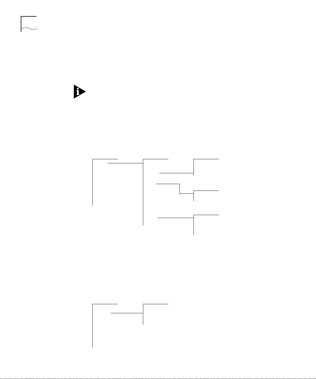
System Menu
From the system menu, you can view the system configuration, set up
your system for management, configure Administration Console interface
parameters, work with nonvolatile data, and reboot the system. (See
Figure 2-1.)
Top-Level Menu system menu baseline menu
➧ system
ethernet softwareUpdate set
fddi
bridge
ip
snmp password telnet menu
analyzer name
script time interval
logout screenHeight
display display
➧ baseline
consoleSpeed
➧ telnet
consoleLock
ctlKeys nvData menu
➧ nvData
reboot restore
requestedState
timeOut
save
examine
reset
Figure 2-1 System-level Functions Menu Hierarchy for Administer Access
Ethernet Menu
From the ethernet menu, you can view information for and name Ethernet
ports. (See Figure 2-2.) For example, to view all Ethernet port statistics, you
enter ethernet at the top-level menu, and then detail at the ethernet
menu.
Top-Level Menu ethernet menu
system summary
➧ ethernet
fddi label
bridge portState
ip
snmp
analyzer
script
logout
Figure 2-2 Ethernet Menu Hierarchy for Administer Access
detail
Page 27

Using Menus to Perform Tasks 2-5
FDDI Menu
From the fddi menu, you can view information about and configure the
FDDI station, paths, MAC, and ports. (See Figure 2-3.) For example, to enable
the LLC service of the FDDI MAC, you enter fddi at the top-level menu, mac
at the fddi menu, and then llcService at the mac menu.
Top-Level Menu fddi menu station menu
system
ethernet
➧ fddi ➧mac
bridge
ip
snmp path menu
analyzer
script tvxLowerBound
logout tmaxLowerBound
➧ station
➧ path
➧ port
Figure 2-3 FDDI Menu Hierarchy for Administer Access
display
connectPolicy
tNotify
statusReporting
display
maxTreq
mac menu
summary
detail
frameErrorThreshold
notCopiedThreshold
llcService
path
port menu
display
lerAlarm
lerCutoff
label
path
Bridge Menu
From the bridge menu, you can view information about and configure
bridge-level parameters, including those for the Spanning Tree Protocol
(STP). You can also configure the bridge at the por t level and administer
packet filters. (See Figure 2-4.) For example, to set the Spanning Tree state
for a bridge port, you enter bridge at the top-level menu, port at the
bridge menu, and stpState at the port menu.
Page 28

2-6 CHAPTER 2: HOW TO USE THE ADMINISTRATION CONSOLE
Top-Level Menu bridge menu port menu address menu
system display summary list
ethernet ipFragmentation detail add
fddi ipxSnapTranslation multicastLimit remove
➧ bridge
ip agingTime stpCost flushAll
snmp stpState stpPriority flushDynamic
analyzer stpPriority
script stpMaxAge
logout stpHelloTime packetFilter menu
addressThreshold stpState find
stpForwardDelay
stpGroupAddress display
➧ port
➧ packetFilter
Figure 2-4 Bridging Menu Hierarchy for Administer Access
IP Menu
From the ip menu, you can view information about and configure Internet
Protocol (IP) interfaces and routes. You can also administer the Address
Resolution Protocol (ARP) and the Routing Information Protocol (RIP), and
ping IP stations. (See Figure 2-5.) For example, to define a new IP interface,
you enter ip at the top-level menu, interface at the ip menu, and then
define at the interface menu.
➧ address
list
create display
delete create
edit delete
load addAdress
assign removeAddress
unassign
➧ addressGroup
➧ portGroup
freeze
addressGroup menu
list
portGroup menu
list
display
create
delete
addPort
removePort
Top-Level Menu ip menu interface menu
system
ethernet
fddi
bridge rip remove
➧ ip
snmp statistics route menu
analyzer
script static
logout remove
➧ interface
➧ route
➧ arp
ping
display
define
modify
display
flush
default
noDefault
arp menu
display
remove
flush
Figure 2-5 IP Menu Hierarchy for Administer Access
Page 29

Using Menus to Perform Tasks 2-7
SNMP Menu
From the snmp menu, you can configure SNMP community strings and
trap reporting. (See Figure 2-6.) For example, to flush all trap reporting
destinations, you enter snmp at the top-level menu, trap at the snmp
menu, and then flush at the trap menu.
Top-Level Menu snmp menu trap menu
system display display
ethernet community addModify
fddi
bridge flush
ip smtProxyTraps
➧ snmp
analyzer
script
logout
➧ trap
remove
Figure 2-6 SNMP Menu Hierarchy for Administer Access
Analyzer Menu
From the analyzer menu, you can selectively choose any Ethernet network
segment attached to a Switch 2200 and monitor its activity using a network
analyzer. (See Figure 2-7.) For example, to add analyzer por ts, you enter
analyzer at the top-level menu, and then add at the analyzer menu.
Top-Level Menu analyzer menu
system display
ethernet add
fddi remove
bridge start
ip stop
snmp
➧ analyzer
script
logout
Figure 2-7 Analyzer Menu Hierarchy for Administer Access
Page 30

2-8 CHAPTER 2: HOW TO USE THE ADMINISTRATION CONSOLE
Selecting Menu
Options
You select a menu option at the selection prompt by entering its name (or
enough of the name to uniquely identify it within the particular menu). For
example, to access the system menu from the top-level menu, you enter:
Select a menu option: system
OR
Select a menu option: sy
Menu options are not case sensitive.
When you enter a menu option, you either go to the next menu in the
hierarchy or you see information for the option you entered. The
information is either a prompt or a screen display. If you enter the menu
option incorrectly, you receive a prompt telling you that what you entered
was not valid or was ambiguous. You must re-enter the command from the
point at which it became incorrect. Expand a truncated command until it
becomes unambiguous.
When a new menu appears, the selection prompt (with its choices in
parentheses) changes to reflect your progression through the menus. For
example, if you enter system at the top-level menu and then baseline at
the system menu, the prompt changes at the next level:
Entering a
command string
Select a menu option (system/baseline):
Once you are familiar with the menu structure, instead of working your way
down the menu hierarchy to a task, you can enter a string of menu options
at a selection prompt to go immediately to a task. For example, the
command string for setting a baseline from the top-level menu looks like
this:
Select a menu option: system baseline set
The most abbreviated version of the same command string is:
Select a menu option: sy b s
When you enter a command string, you move to the last menu level or
option you entered in the command string, and information relevant to that
command is displayed. I t may be a menu, prompt, or screen display.
Page 31

Using Menus to Perform Tasks 2-9
If you enter a command incorrectly, you receive a prompt telling you that
what you entered was not valid or was ambiguous. You must re-enter the
command from the point at which it became incorrect.
Entering Values When you reach the level at which you perform a specific task, you are
prompted for a value. The prompt usually shows all valid values (if
applicable) and sometimes a suggested default value. The default might be
the system default or the current user-defined value of that parameter.
The valid values are displayed in parentheses. The default value is in
brackets. In this example, (
[
Enabled], shown in brackets, is the default:
Enter a new value (disabled,enabled) [enabled]:
disabled, enabled) are the valid values.
Entering values in
command strings
A command string can also contain the value of a command parameter.
If you enter a value at the end of a command string, the task is completed,
and you are returned to the previous menu. For example, to disable a
baseline from the top-level menu, enter :
Select a menu option: system baseline requestedState
disabled
Getting Out To return to the menu one step higher in the hierarchy or to cancel an
operation that you are currently performing, enter
q, followed by [Return].
To quickly move to the top-level menu without backtracking through
menus, press [Esc] (the Escape key). You immediately return to the top-level
menu.
To completely leave the Administration Console, see the section “Exiting the
Administration Console” on page 2-17.
Page 32

2-10 CHAPTER 2: HOW TO USE THE ADMINISTRATION CONSOLE
Administration Console Interface Parameters
Adjusting the
Screen Height
You can change two Administration Console interface parameters: the
screen height and the functioning of the reboot and abort control keys.
You can change the Administration Console’s screen height to increase or
decrease the space available for displaying information.
The screen height setting does not affect the way the system displays menus.
The screen height setting controls the way the system displays information
that results from your use of the menus, such as when you request statistical
summaries.
You can configure the screen height to be between 20 to 200 lines or zero
(0) for infinite; the default is 24. Most terminal screens have a height of 24
lines.
Each time the screen output reaches the designated screen height, you are
prompted to press a key to display more information. To receive no
prompts, set the screen height to infinite (0). At this setting, however, the
screen output might scroll beyond the screen, depending on your screen
size.
Top-Level Menu
➧ system
ethernet
fddi
bridge
ip
snmp
analyzer
script
logout
display
softwareUpdate
baseline
consoleSpeed
telnet
password
name
time
➧ screenHeight
consoleLock
ctlKeys
nvData
reboot
To set the screen height:
1 From the top level of the Administration Console, enter :
system screenHeight
You are prompted for a screen height value.
2 Enter the screen height in lines (20 to 200). To receive no prompts, set the
screen height to infinite (0).
Example:
Enter new screen height or 0 for infinite height [24]: 60
Your are prompted about whether you want this value to be the default.
3 Enter
y (yes) to use this screen height as the default for future
Administration Console sessions. Enter
n (no) if you want this screen height
to be in effect only for this session.
Page 33

Remote Access Parameters 2-11
Example:
Do you want this to be the new default screen height?
(y/n):
y
Top-Level Menu
➧ system
ethernet
fddi
bridge
ip
snmp
analyzer
script
logout
Disabling the
Reboot and
Abort Keys
display
softwareUpdate
baseline
consoleSpeed
telnet
password
name
time
screenHeight
consoleLock
➧ ctlKeys
nvData
reboot
As shipped, the Administration Console allows you to use the [Ctrl + X] or
[Ctrl + C] key combinations within the Administration Console. These key
strokes allow you to reboot the system [Ctrl + X] or restart the
Administration Console [Ctrl + C]. You can change this setting to disable
both of these features.
CAUTION: If you disable the control keys, only use [Ctrl + C] if instructed to
by a Technical Support representative. Using [Ctrl + C] might irregularly
terminate an Administration Console session.
To enable or disable the reboot and abort control keys:
1 From the top level of the Administration Console, enter :
system ctlKeys
You are prompted for whether to enable or disable the functionality, as
shown here:
Enter new value (disabled,enabled) [enabled]:
2 Enter enabled or disabled at the prompt.
Remote Access Parameters
Preventing
Disconnections
You can reach the Administration Console remotely through a telnet or
rlogin session. You can set parameters to prevent disconnections when
another user remotely accesses the Administration Console, to enable the
Switch 2200 to end remote sessions after a specified time period, and to
specify the time interval before remote sessions are ended.
Because only a single shell is supported by the Administration Console, you
might be disconnected from your session if someone else remotely accesses
the Administration Console. A terminal connected through the Console
serial port can be disconnected by a telnet or rlogin connection.
Page 34

2-12 CHAPTER 2: HOW TO USE THE ADMINISTRATION CONSOLE
To ensure that your Administration Console session will not be pre-empted
by remote access, you can lock the Administration Console. Remote access
is prohibited only for that particular session.
The Administration Console is always locked when you are in the middle of a
command. For example, the Administration Console is locked during a
software update.
To lock the Administration Console:
Top-Level Menu
➧ system
ethernet
bridge
ip
snmp
analyzer
script
logout
display
softwareUpdate
baseline
consoleSpeed
telnet
password
name
time
screenHeight
➧ consoleLock
ctlKeys
nvData
reboot
1 From the top level of the Administration Console, enter :
system consoleLock
You are prompted to unlock (off ) or lock (on) the Administration Console as
shown here:
Enter new value (off,on) [on]:
2 Enter off to unlock the Administration Console or on to lock it.
Enabling Timeout
of Remote Sessions
Top-Level Menu
➧ system
ethernet
bridge
ip
snmp
analyzer
script
logout
display
softwareUpdate
baseline
consoleSpeed
➧ telnet
password
name
time
screenHeight
consoleLock
ctlKeys
nvData
reboot
➧ timeOut
interval
You can configure the Switch 2200 to disconnect remote sessions after a
user-specified time interval of no activity. B y default, the telnet timeout is
disabled.
To enable or disable the telnet timeout:
1 From the top level of the Administration Console, enter :
system telnet timeOut
2 Enter the telnet timeout state (off or on).
The default time interval is 30 minutes. To change this value, follow the
instructions in the next section.
Page 35

Running Scripts of Administration Console Tasks 2-13
Setting Timeout
Interval for Remote
Sessions
Top-Level Menu
➧ system
ethernet
bridge
ip
snmp
analyzer
script
logout
display
softwareUpdate
baseline
consoleSpeed
➧ telnet
password
name
time
screenHeight
consoleLock
ctlKeys
nvData
reboot
timeOut
➧ interval
Running Scripts of Administration Console Tasks
You can set the timeout interval for remote sessions to any value from 30
minutes to 60 minutes. B y default, the timeout interval is 30 minutes.
To set the telnet timeout interval:
1 From the top level of the Administration Console, enter :
system telnet interval
2 Enter the telnet timeout inter val (30 minutes to 60 minutes).
You can use scripts to expedite and automate Administration Console tasks.
Any command you enter in the Administration Console can become part of
a script. You can even script your entire system setup so that you can repeat
the exact setup on another Switch 2200.
You create scripts in an ASCII-based line editor, such as EMACS or vi. To run
them from the Administration Console, you must access the directory where
your scripts are stored. When writing scripts, you can use the number
symbol (#) to identify comments in the script.
Top-Level Menu
system
ethernet
fddi
bridge
ip
snmp
analyzer
➧ script
logout
To run a script:
1 From the top level of the Administration Console, enter :
script
You are prompted for information about where you have stored the script
you want to run: host IP address, file path name, user name, and password.
Press [Return] at any prompt to use the value in brackets.
2 Enter the host IP address of the system where the script resides.
3 Enter the path name.
4 Enter your user name.
5 Enter your password.
6 Enter the name of the script.
Page 36

2-14 CHAPTER 2: HOW TO USE THE ADMINISTRATION CONSOLE
The task you scripted is run in the Administration Console.
The next example shows how you can script these tasks to initially
configure your system:
■ Setting up the Console port baud rate
■ Setting the system name
■ Assigning an IP address for management
■ Checking the IP connection by pinging the Switch 2200
■ Enabling Spanning Tree on the system
■ Setting up SNMP trap reporting
Page 37

Running Scripts of Administration Console Tasks 2-15
# This script performs some start-up configurations.
#
# Set the Console serial port baud rate.
#
system consoleSpeed
300 # Console port baud rate
#
# Set the system name
#
system name
Engineering Switch2200_4
#
# Assign an IP address to the Switch 2200.
#
ip interface define
158.101.112.99 # IP address for the system
255.255.0.0 # subnet mask
158.101.255.255 # broadcast address
1 # cost
all # ports
#
ip interface display
#
# Validate access to management workstation
#
ip ping
158.101.112.26 # management workstation address
#
# Enable the Spanning Tree Protocol
#
bridge stpState enabled
#
# Configure my node as an SNMP trap destination
#
snmp trap add
158.101.112.26 # management workstation address
all # turn on all traps
q # no more trap destinations
#
snmp trap display
#
Page 38

2-16 CHAPTER 2: HOW TO USE THE ADMINISTRATION CONSOLE
Getting Help in the Administration Console
Online Help The Administration Console online Help provides an overview of the
General online help To get help using the Administration Console, enter ?. The system displays
Help for specific
menu options
Viewing More
Levels of Menu
Options
If you need assistance when using the Administration Console, it has online
Help and an outlining feature, both of which can be accessed from any
menu level. These features are described in this section.
Administration Console and lets you access information about any menu
option.
general instructions for using the Administration Console.
To get help for a specific menu option, enter ? and the name of the option
for which you want help. The system displays instructions, if available, for
using that option.
For example, to get help on the
ethernet option on the top-level menu,
enter:
? ethernet
The outlining feature allows you to list the menu options that fall lower
than the current menu in the hierarchy. The default displays up to three
levels of options.
To display the outline of available options below the current menu
(up to three levels), enter
outline (or o).
You can add a number to the command to modify how many levels you
display. For example, to display two levels, enter:
outline 2
Page 39

Exiting the Administration Console 2-17
Exiting the Administration Console
Top-Level Menu
system
ethernet
fddi
bridge
ip
snmp
analyzer
script
➧ logout
If you are using an rlogin session to access the system, exiting will terminate
the session. If you are accessing the system through the Console serial port,
exiting returns you to the password prompt.
To exit from the Administration Console:
1 Return to the top level of the Administration Console, if you are not already
there, by pressing the [ESC] key.
2 From the top-level menu, enter:
logout
Page 40

II
SYSTEM-LEVEL FUNCTIONS
Chapter 3 Configuring Management Access to the System
Chapter 4 Administering Your System Environment
Chapter 5 Baselining Statistics
Chapter 6 Saving, Restoring, and Resetting Nonvolatile Data
Page 41

Page 42

3
CONFIGURING MANAGEMENT
A
CCESS TO THE SYSTEM
This chapter describes how to configure management access to the
SuperStack™ II Switch 2200 stackable switch through a serial connection or
an IP interface. It also describes how to configure the Switch 2200 so that
you can manage it using the Simple Network Management Protocol
(SNMP).
About Management Access
Using a Serial
Connection
Using an IP
Interface
You can access the Administration Console directly through the console
serial port. Alternatively, from a PC or workstation, you can access the
Administration Console through an Ethernet or FDDI port that has an IP
interface configured for it. Once you establish an IP interface, you can also
set up the system to be managed by an SNMP-based network management
application, such as 3Com’s Transcend® Enterprise Manager.
Direct access through the console serial port is often preferred because it
allows you to stay attached during system reboots.
See the SuperStack™ II Switch 2200 Getting Started Guide for console port
pin-outs.
Serial connections are often more readily available at a site than Ethernet
connections. A Macintosh or PC attachment can use any terminal emulation
program when connecting to the Console serial port. A workstation
attachment under UNIX can use an emulator such as tip.
An IP interface allows you to manage the system in-band through any
Ethernet or FDDI port. Once an IP interface is configured, you can rlogin or
telnet to the Administration Console using TCP/IP from a host, or you can
access the SNMP agent from an external management application. The IP
interface has a unique IP address.
Page 43

3-2 CHAPTER 3: CONFIGURING MANAGEMENT ACCESS TO THE SYSTEM
In-band or
Out-of-band?
Setting Up the Console Serial Port
Top-Level Menu
➧ system
ethernet
fddi
bridge
ip
snmp
analyzer
script
logout
display
softwareUpdate
baseline
➧ consoleSpeed
telnet
password
name
time
screenHeight
consoleLock
ctlKeys
nvData
reboot
By default, the Switch 2200 system provides in-band management through
its Ethernet and FDDI ports. In-band management, management using the
same network that carries regular data traffic, is often the most convenient
and inexpensive way to access your system. If you are using a dedicated
network for management data, then you are managing your network
out-of-band.
If Spanning Tree is enabled and the port is in the blocking state, in-band
management is not functional.
The default baud rate for the Console serial port is 9600. You might need to
change the baud rate to match the port speed on your terminal.
Baud rate changes take effect immediately after you confirm the change.
Adjust the baud rate of your terminal or terminal emulator appropriately to
re-establish communication using the console serial port.
To set the baud rate for the Console serial port:
1 From the top level of the Administration Console, enter :
system consoleSpeed
2 Enter the baud rate for the serial por t.
The system supports the following baud rates: 19200, 9600, 4800, 2400,
1200, and 300.
If you are connected to the Console serial port when you set the baud rate
for that serial port, the following message is displayed:
Changing the baud rate may cause a loss of communication
since you are currently connected via the serial port.
Are you sure you want to change the baud rate? (y/n):
If you respond y (yes), the baud rate is changed immediately. At this time,
you lose the ability to communicate on the serial port unless you adjust the
baud rate of your terminal or terminal emulator (tip) appropriately. If you
respond
n (no), the baud rate does not change, and the previous menu is
displayed.
Page 44

Setting Up an IP Interface for Management 3-3
Setting Up an
IP Interface for
Management
General Setup
Process
Administering
Interfaces
IP is a standard networking protocol used for communications among
various networking devices. To access the system using TCP/IP or to manage
the system using SNMP, you must set up IP for your system as described in
this section.
You must first define an interface, which includes assigning an IP address to
that interface, and then ping your IP management station to ensure that the
connection is alive.
Assign an IP host address to every port for system management.
Then you can finalize your IP setup by ensuring that the configurations of
the following are correct for your network and changing them as necessary:
■ Routes (See page 3-7)
■ Address Resolution Protocol (ARP) cache (See page 3-11)
■ Routing Information Protocol (RIP) (See page 3-12)
You can monitor IP activity for your system by displaying the IP statistics at
any time.
You define interfaces to establish the relationship between the ports on
your system and the subnets in your IP network. You can have up to 32
addresses on a single port and you can assign up to 17 ports per interface.
An IP interface has the following information associated with it:
■ IP Address
This address is specific to your network. Choose it from the range of
addresses assigned to your organization. This address defines both the
number of the network to which the interface is attached and the
interface’s host number on that network.
■ Subnet Mask
A subnet mask is a 32-bit number that uses the same format and
representation as an IP address. The subnet mask determines which bits in
the IP address are interpreted as the network number, which as the subnet
number, and which as the host number. Each IP address bit corresponding
to a 1 in the subnet mask is in the network/subnet part of the address. Each
IP address bit corresponding to a 0 is in the host part of the IP address.
Page 45

3-4 CHAPTER 3: CONFIGURING MANAGEMENT ACCESS TO THE SYSTEM
■ Broadcast Address
The system uses the IP address when it broadcasts packets to other stations
on the same subnet. In particular, the system uses this address for sending
RIP updates. By default, the system uses a directed broadcast (all 1s in
the host field).
■ Cost
The system uses this number, between 1 and 15, when calculating route
metrics. Unless your network has special requirements, you should assign a
cost of 1 to all interfaces.
■ Por t s
A single interface might contain several bridge ports. All of the ports
corresponding to one interface share the same IP address, subnet mask,
broadcast address, and cost. The Switch 2200 contains 17 ports: 1 FDDI
and 16 Ethernet.
Be sure that the port to which your management station is attached is
included in an interface.
Top-Level Menu
system
ethernet
➧ interface
fddi
bridge
➧ ip
snmp
analyzer
script
logout
route
arp
rip
ping
statistics
➧ display
define
modify
remove
Displaying Interfaces
You can display a table that shows all IP interfaces configured for the
system, including their parameter settings.
To display IP interface information, enter the following command from the
Administration Console top-level menu:
ip interface display
As shown in this example, the current configuration is displayed.
It contains IP forwarding and RIP information as well as the IP interface
information.
Page 46

Setting Up an IP Interface for Management 3-5
IP forwarding is enabled, RIP is active, ICMP router discovery is
disabled.
Index IP address Subnet mask Cost Ports
1 158.101.1.1 255.255.255.0 1 1
2 158.101.4.1 255.255.255.0 1 2
3 158.101.6.1 255.255.255.0 1 5
4 158.101.8.1 255.255.255.0 1 8
Defining an Interface
When you define an interface, you define the interface’s IP address, subnet
mask, broadcast address, cost, and the collection of system ports associated
with the interface.
Table 3-1 shows the recommended settings for the IP interface parameters
if you are setting up the system for management.
Table 3-1 Recommended Settings for IP Management Access
Parameter Recommended Setting
IP address User defined
Subnet mask User defined
Broadcast address Directed (all 1s in the host field)
Cost 1
Ports all
Top-Level Menu
system
ethernet
➧ interface
fddi
bridge
➧ ip
snmp
analyzer
script
logout
route
arp
rip
ping
statistics
display
➧ define
modify
remove
Defining an interface defines the IP broadcast domain for frames sourced
from the attached segment. To avoid unintentional filtering of IP broadcasts,
3Com recommends that you include all ports. I f you do not assign all ports
to this interface, be sure that you include the port to which your network
management station is attached.
To define an IP interface:
1 From the top level of the Administration Console, enter :
ip interface define
You are prompted for the interface’s parameters. To use the value in
brackets, press [Return] at the prompt.
2 Enter the IP address of the inter face.
Page 47

3-6 CHAPTER 3: CONFIGURING MANAGEMENT ACCESS TO THE SYSTEM
3 Enter the subnet mask of the network to which the inter face is to be
connected.
4 Enter the broadcast address to be used on the inter face.
5 Enter the cost value of the interface.
6 Enter the por t(s) that you want to include in the interface. Separate
nonconsecutive ports with commas (,). Enter a consecutive series of ports
using a hyphen (-).
Example:
Enter IP address: 158.101.1.1
Enter subnet mask [255.255.0.0]: 255.255.255.0
Enter broadcast address [158.101.1.255]:
Enter cost [1]:
Ports 1-2=FDDI, 3-18=Ethernet
Select port(s) (1-18|all):
If you physically change the configuration of your system after defining IP
interfaces, the ports designated for those interfaces might no longer be valid.
You should reconfigure your interfaces.
2-4,8
Top-Level Menu
system
ethernet
➧ interface
fddi
bridge
➧ ip
snmp
analyzer
script
logout
route
arp
rip
ping
statistics
display
define
➧ modify
remove
Modifying an Interface
To modify an IP interface that you have already defined:
1 From the top level of the Administration Console, enter :
ip interface modify
You are prompted for the interface parameters. Press [Return] at the
prompts for which you do not want to modify the value in parentheses.
2 Modify the existing inter face parameters by entering a new value at the
prompt.
Page 48

Setting Up an IP Interface for Management 3-7
Removing an Interface
You might want to remove an interface if you no longer need to
communicate with IP on the ports associated with that interface.
Top-Level Menu
system
ethernet
➧ interface
fddi
bridge
➧ ip
snmp
analyzer
script
logout
display
route
define
arp
modify
rip
ping
➧ remove
statistics
Administering
Routes
To remove an IP interface definition:
1 From the top level of the Administration Console, enter :
ip interface remove
2 Enter the index numbers of the inter faces you want to remove.
Each system maintains a table of routes to other IP networks, subnets, and
hosts. You can either make static entries in this table using the Administration Console or configure the system to use RIP to automatically exchange
routing information.
Each routing table entry contains the following information:
■ Destination IP Address and Subnet Mask
These elements define the address of the destination network, subnet, or
host. A route matches a given IP address if the bits in the IP address that
corresponds to the bits set in the route subnet mask match the route
destination address. When it forwards a packet, if the system finds more
than one routing table entry matching an address (for example, a route to
the destination network and a route to the specific subnet within that
network), it will use the most specific route (that is, the route with the most
bits set in its subnet mask).
■ Routing Metric
This metric specifies the number of networks or subnets that a packet must
pass through to reach its destination. This metric is included in RIP updates
to allow routers to compare routing information received from different
sources.
Page 49

3-8 CHAPTER 3: CONFIGURING MANAGEMENT ACCESS TO THE SYSTEM
■ Gateway IP Address
This address tells the router how to forward packets whose destination
address matches the route’s IP address and subnet mask. The system
forwards such packets to the indicated gateway.
■ Status
The status of the route provides the information described in Table 3-2.
Table 3-2 Route Status
Status Description
Direct Route to a directly connected network
Static Route was statically configured
Learned Route was learned using indicated protocol
Timing out Route was learned but is partially timed out
Timed out Route has timed out and is no longer valid
In addition to the routes to specific destinations, the routing table can
contain an additional entry, called the default route. The system uses the
default route to forward packets that do not match any other routing table
entry. You might want to use a default route in place of routes to numerous
destinations that all have the same gateway IP address.
Top-Level Menu
system
ethernet
bridge
➧ route
➧ ip
snmp
analyzer
script
logout
interface
arp
rip
ping
statistics
➧ display
static
remove
flush
default
noDefault
Displaying the Routing Table
You can display the routing table for the system to determine which routes
are configured and if they are operating.
To display the contents of the routing table, enter the following from the
top level of the Administration Console:
ip route display
In the following example, routes for the Switch 2200 are displayed. The
configuration of RIP is indicated in the status display.
Destination Subnet mask Metric Gateway Status
158.101.4.0 255.255.255.0 2 158.101.2.8 Static
158.101.3.0 255.255.255.0 2 158.101.1.2 Learned(RIP)
158.101.2.0 255.255.255. 1 -- Direct
158.101.1.0 255.255.255.0 1 -- Direct
Default Route -- 5 158.101.1.2 Learned (RIP)
Page 50

Top-Level Menu
system
ethernet
fddi
➧ route
bridge
➧ ip
snmp
analyzer
script
logout
interface
arp
rip
ping
statistics
display
➧ static
remove
flush
default
noDefault
Setting Up an IP Interface for Management 3-9
Defining a Static Route
You might want to define a static route to transmit system traffic, such as
system pings or SNMP response, through a consistent route. Before you
define static routes, you must define at least one IP interface. (See “Defining
an Interface” on page 3-5.) Static routes remain in the table until you
remove them, or until you remove the corresponding interface. Static routes
take precedence over dynamically learned routes to the same destination.
To define a static route:
1 From the top level of the Administration Console, enter :
ip route static
You are prompted for the route’s parameters. To use the value in brackets,
press [Return] at the prompt.
2 Enter the destination IP address of the route.
3 Enter the subnet mask of the route.
Top-Level Menu
system
ethernet
fddi
➧ route
bridge
➧ ip
snmp
analyzer
script
logout
interface
arp
rip
ping
statistics
display
static
➧ remove
flush
default
noDefault
4 Enter the gateway IP address of the route.
A static route is defined in the following example:
Enter destination IP address: 158.101.4.0
Enter subnet mask [255.255.0.0]: 255.255.255.0
Enter gateway IP address: 158.101.2.8
Removing a Route
To remove a route:
1 From the top level of the Administration Console, enter :
ip route remove
2 Enter the destination IP address of the route.
3 Enter the subnet mask of the route.
The route is immediately deleted from the routing table.
Page 51

3-10 CHAPTER 3: CONFIGURING MANAGEMENT ACCESS TO THE SYSTEM
Flushing a Route
Flushing deletes all learned routes from the routing table.
Top-Level Menu
system
ethernet
fddi
➧ route
bridge
➧ ip
snmp
analyzer
script
logout
interface
arp
rip
ping
statistics
display
static
remove
➧ flush
default
noDefault
To flush all learned routes, enter the following from the top level of the
Administration Console:
ip route flush
All learned routes are immediately deleted from the routing table.
Setting the Default Route
The system uses the default route to forward packets that do not match any
other routing table entry. A system can learn a default route using RIP, or
you can configure a default route statically.
If a system’s routing table does not contain a default route, either statically
configured or learned using RIP, then it cannot forward a packet that does
not match any other routing table entry. If it cannot for ward a packet for
this reason, then it drops the packet and sends an ICMP “destination
unreachable” message to the host that sent the packet to notify it of the
problem.
Top-Level Menu
system
ethernet
fddi
➧ route
bridge
➧ ip
snmp
analyzer
script
logout
Top-Level Menu
system
ethernet
fddi
➧ route
bridge
➧ ip
snmp
analyzer
script
logout
interface
arp
rip
ping
statistics
interface
arp
rip
ping
statistics
display
static
remove
flush
➧ default
noDefault
display
static
remove
flush
default
➧ noDefault
To statically configure the default route:
1 From the top level of the Administration Console, enter :
ip route default
2 Enter the gateway IP address of the route.
The default route is immediately added to the routing table.
Removing the Default Route
To remove a default route, enter the following from the top level of the
Administration Console:
ip route noDefault
The default route is immediately removed from the routing table.
Page 52

Setting Up an IP Interface for Management 3-11
Administering
the ARP Cache
Top-Level Menu
system
ethernet
interface
fddi
route
bridge
➧ arp
➧ ip
Top-Level Menu
➧ ip
snmp
analyzer
script
logout
system
ethernet
fddi
bridge
snmp
analyzer
script
logout
rip
ping
statistics
interface
route
➧ arp
rip
ping
statistics
➧ display
remove
flush
display
➧ remove
flush
The Switch 2200 uses the Address Resolution Protocol (ARP) to find the
MAC addresses corresponding to the IP addresses of hosts and routers on
the same subnets. An ARP cache is a table of known IP addresses and their
corresponding MAC addresses.
Displaying the ARP Cache
To display the contents of the ARP cache, enter the following command
from the top level of the Administration Console:
ip arp display
The contents of the ARP cache are displayed as shown in this example:
RIP is active.
IP Address MAC Address Interface
158.101.1.112 08-00-1e-31-a6-2 1
158.101.1.117 08-00-1e-65-21-07 1
Removing an ARP Cache Entry
You might want to remove an entry from the ARP cache if the MAC address
has changed.
To remove an entry from the ARP cache:
1 From the top level of the Administration Console, enter :
ip arp remove
2 Enter the IP address you want to remove.
The address is immediately removed from the table. If necessar y, the system
will subsequently use ARP to find the new MAC address corresponding to
that IP address.
Page 53

3-12 CHAPTER 3: CONFIGURING MANAGEMENT ACCESS TO THE SYSTEM
Flushing ARP Cache Entries
You might want to delete all entries from the ARP cache if the MAC address
Top-Level Menu
system
ethernet
fddi
bridge
➧ arp
➧ ip
snmp
analyzer
script
logout
interface
route
rip
ping
statistics
display
remove
➧ flush
has changed.
To remove all entries from the ARP cache, enter the following command
from the top level of the Administration Console:
ip arp flush
The ARP cache entries are immediately removed from the table.
Setting the RIP
Top-Level Menu
system
ethernet
interface
fddi
route
bridge
snmp
analyzer
script
logout
arp
➧ rip
ping
statistics
➧ ip
Pinging an IP
You can select a RIP mode that is appropriate for your network. RIP can
Mode
operate in one of two modes:
■ Off — The station ignores all incoming RIP packets and does not generate
any RIP packets of its own.
■ Passive — The station processes all incoming RIP packets and responds to
explicit requests for routing information, but it does not broadcast periodic
or triggered RIP updates.
RIP default mode By default, RIP operates in passive mode.
To set the RIP operating mode:
1 From the top level of the Administration Console, enter :
ip rip
2 Enter the RIP mode (off or passive). To use the value in brackets, press
[Return] at the prompt.
See the following example:
Select RIP mode (off, passive) [passive]: off
Once you have set up your IP interface, you might want to check to see if
Station
the Switch 2200 system can communicate with other systems over the IP
network. To check, you can “ping” the IP address of your management
station.
Page 54

Top-Level Menu
system
ethernet
fddi
bridge
➧ ip
snmp
➧ ping
analyzer
script
logout
interface
route
arp
rip
statistics
Setting Up an IP Interface for Management 3-13
Pinging uses the Internet Control Message Protocol (ICMP) echo facility to
send an ICMP echo request packet to the IP station you specify. It then
waits for an ICMP echo reply packet. Possible responses from pinging are:
■ Alive
■ No answer
■ Network is unreachable. A network is unreachable when there is no route to
that network.
To ping an IP station:
1 From the top level of the Administration Console, enter :
ip ping
2 Enter the IP address of the station you want to ping.
IP Address: 192.9.200.40
You could receive one of the following responses:
192.9.200.40 is alive
OR
no answer from 192.9.200.40
For a remote IP address, you can also receive the following response:
Network is unreachable
You should receive a response that the address you pinged is Alive. If you do
not receive this response, be sure that you have defined the correct
interface values.
Page 55

3-14 CHAPTER 3: CONFIGURING MANAGEMENT ACCESS TO THE SYSTEM
Top-Level Menu
system
ethernet
fddi
bridge
➧ ip
snmp
analyzer
➧ statistics
script
logout
Displaying IP
Statistics
interface
route
arp
rip
ping
The IP statistics you can view are described in Table 3-3.
Table 3-3 IP Statistics
Field Description
inReceives Total number of IP datagrams received, including those with errors
forwDatagrams Number of datagrams that the IP station attempted to forward
inDelivers Number of datagrams that the IP station delivered to local IP client
protocols
outRequests Number of datagrams that local IP client protocols passed to IP for
transmission
outNoRoutes Number of datagrams that the IP station discarded because there
was no route to the destination
inHdrErrors Number of datagrams that the IP station discarded because the IP
header contained errors
inAddrErrors Number of datagrams that the IP station discarded because of an
error in the source or destination IP address
To display IP statistics, enter the following from the top level of the
Administration Console:
ip statistics
Statistics are displayed, as shown in this example:
IP forwarding is enabled, RIP is active, ICMP router discovery is
disabled.
inReceives forwDatagrams inDelivers outRequests
51213 49743 3227 2285
outNoRoutes inHdrErrors inAddrErrors
273 7 0
Page 56

Setting Up SNMP on Your System 3-15
Setting Up SNMP on Your System
Displaying SNMP
Settings
Top-Level Menu
system
ethernet
fddi
bridge
ip
➧ snmp
analyzer
script
logout
➧ display
community
trap
To manage the Switch 2200 from an external management application, you
must configure SNMP community strings and set up trap reporting as
described in this section.
You can manage the Switch 2200 using an SNMP-based external
management application. This application (an SNMP manager) sends
requests to the Switch 2200 system, where they are processed by the
Switch SNMP agent.
The SNMP agent provides access to the collection of information about the
Switch 2200. In addition, a Switch 2200 SNMP agent sends traps to an
SNMP manager to report significant events. Access to system information
through SNMP is controlled by community strings.
For more information about using SNMP to manage the Switch 2200, see
Chapter 3: Management Access: Protocols in the SuperStack™ II Switch 2200
Operation Guide.
You can display the current Switch 2200 SNMP configurations for the
community strings.
To display SNMP settings, enter the following from the top level of the
Administration Console:
snmp display
The community string settings are displayed as shown here:
Read-only community is public
Read-write community is private
Configuring
Community Strings
A community string is an octet string, included in each SNMP message, that
controls access to system information. The Switch 2200 SNMP agents
internally maintain two community strings that you can configure:
■ Read-only community strings with the default “public”
■ Read-write community strings with the default “private”
When an SNMP agent receives an SNMP request, the community string
in the request is compared with the community strings configured for the
agent. SNMP get, get-next, and set requests are valid if the community string
Page 57

3-16 CHAPTER 3: CONFIGURING MANAGEMENT ACCESS TO THE SYSTEM
in the request matches the agent’s read-write community. Only the SNMP
get and get-next requests are valid if the community string in the request
matches the read-only community.
Top-Level Menu
system
ethernet
fddi
bridge
ip
➧ snmp
analyzer
script
logout
Community string
length
display
➧ community
trap
Administering
SNMP Trap
Reporting
When you set a community string, you can specify any value up to 48
characters long.
To set a community string:
1 From the top level of the Administration Console, enter :
snmp community
You are prompted for a read-only community value and then a read-write
community value. If you do not want to change the value of a community
string, press [Return] at either prompt.
2 At the read-only prompt, enter the community string.
3 At the read-write prompt, enter the community string.
For network management applications, you can use the Administration
Console to manually administer the trap reporting address information.
Displaying Trap Information
Displaying the trap reporting information shows you the various SNMP traps
and the current configured destinations, as well as whether the proxying of
remote SMT traps is enabled or disabled.
Top-Level Menu
system
ethernet
fddi
bridge
➧ trap
ip
➧ snmp
analyzer
script
logout
display
community
➧ display
addModify
remove
flush
smtProxyTraps
To show the configured trap reporting information, enter the following from
the top level of the Administration Console:
snmp trap display
Page 58

Setting Up SNMP on Your System 3-17
Here is an example display of the SNMP trap reporting information:
Trap Descriptions:
Trap #Description
1 MIB II: Coldstart
2 MIB II: Authentication Failure
3 Bridge MIB: New Root
4 Bridge MIB: Topology Change
5 LANplex Systems MIB: System Overtemperature
10 LANplex Systems MIB: Address Threshold
12 LANplex Opt FDDI MIB: SMT Hold Condition
13 LANplex Opt FDDI MIB: SMT Peer Wrap Condition
14 LANplex Opt FDDI MIB: MAC Duplicate Address
Condition
15 LANplex Opt FDDI MIB: MAC Frame Error Condition
16 LANplex Opt FDDI MIB: MAC Not Copied Condition
17 LANplex Opt FDDI MIB: MAC Neighbor Change
18 LANplex Opt FDDI MIB: MAC Path Change
19 LANplex Opt FDDI MIB: Port LER Condition
20 LANplex Opt FDDI MIB: Port Undesired Connection
21 LANplex Opt FDDI MIB: Port EB Error Condition
22 LANplex Opt FDDI MIB: Port Path Change
Top-Level Menu
system
ethernet
fddi
bridge
➧ trap
ip
➧ snmp
analyzer
script
logout
display
community
display
➧ addModify
remove
flush
smtProxyTraps
Trap Destinations Configured:
Address Trap Numbers Enabled
158.101.112.3 1-10, 12-21
Proxying of remote SMT events is disabled
Configuring Trap Reporting
You can add new trap reporting destination configurations or you can
modify an existing configuration. You can define up to ten destination
addresses and the set of traps that are sent to each destination address.
To add a new trap reporting destination configuration or modify a current
one:
1 From the top level of the Administration Console, enter :
snmp trap addModify
The system prompts you for a trap destination address, that is, the IP
address of the SNMP manager that will receive the traps.
2 Enter an IP address of the SNMP manager (destination address) .
Page 59

3-18 CHAPTER 3: CONFIGURING MANAGEMENT ACCESS TO THE SYSTEM
3 Enter the trap number(s).
Separate a series of more than two trap numbers with a hyphen (-) and
nonsequential trap numbers by commas. Enter
the traps for the destination.
The trap numbers you enter allow the trap specified by that number to be
sent to the destination address when the corresponding event occurs. No
unlisted traps are transmitted.
This example shows a trap configuration:
Enter the trap destination address: 158.101.222.3
Enter the trap numbers to enable (1-5,10,12-22|all)
[1-5,10,12-22]:
Address Error If the destination address you entered is not a valid end-station or if the
all
agent does not have a route to the destination, you receive this message:
Trap address invalid or unreachable
If you see this message, confirm the address of the end-station and confirm
that it is online.
all if you want to enable all
Top-Level Menu
system
ethernet
fddi
bridge
➧ trap
ip
➧ snmp
analyzer
script
logout
display
community
display
addModify
➧ remove
flush
smtProxyTraps
Removing Trap Destinations
When you remove a destination, no SNMP traps will be repor ted to that
destination.
To remove a destination:
1 From the top level of the Administration Console, enter :
snmp trap remove
You are prompted for a trap destination address, that is, the IP address of
the SNMP manager that will no longer receive the traps.
2 Enter the SNMP trap repor ting destination address you want to remove.
The destination address is removed and you return to the previous menu.
Page 60

Top-Level Menu
system
ethernet
fddi
bridge
➧ trap
ip
➧ snmp
analyzer
script
logout
display
community
display
addModify
remove
➧ flush
smtProxyTraps
Setting Up SNMP on Your System 3-19
Flushing Trap Destinations
When flushing the SNMP trap reporting destinations, you remove all trap
destination address information for the SNMP agent.
To flush all SNMP trap reporting destinations:
1 From the top level of the Administration Console, enter :
snmp trap flush
You receive the following prompt:
Are you sure? (n/y) [y]:
2 Enter y (yes) or n (no) at the prompt.
If you enter
y, the addresses are immediately flushed. If you enter n, you
return to the previous menu.
Setting Up SMT Event Proxying
FDDI SMT events, which occur on the FDDI ring, can be repor ted to stations
through the Status Report Protocol. Several SNMP traps, defined in the
LANplex Optional FDDI MIB, correspond to some of these events and
conditions. If you want your Switch 2200 to report remote SMT events as
SNMP traps, you must enable proxying of remote SMT events in that Switch
2200 system.
Local SMT events are automatically reported by the SNMP agent in a Switch
2200 system.
If you have a single Switch 2200 on your network and you have no other
way to access FDDI information, then you should enable proxying of SMT
events. This configuration provides access to the events occurring locally on
the Switch 2200 and to those reported by other stations on the FDDI ring.
If you have multiple Switch 2200s on your FDDI network all reporting to the
same SNMP management station, then you can do one of the following:
■ On only one Switch 2200, 1) enable local SNMP traps as described in the
“Configuring Trap Repor ting” on page 3-17 and 2) enable proxying
of remote SMT events. On all other Switch 2200s in your network,
1) disable proxying of remote SMT events and 2) enable only SNMP traps
that are not SMT-related. SMT-related traps include all of those in the
LANplex Optional FDDI MIB. This configuration provides access to the events
Page 61

3-20 CHAPTER 3: CONFIGURING MANAGEMENT ACCESS TO THE SYSTEM
occurring locally on the one Switch 2200 and to those reported by other
stations on the FDDI ring (including other Switch 2200s).
■ Enable local SNMP traps and disable the proxying of remote SMT events on
every Switch 2200 in your network. Local traps will be reported to the
management station (which will cover all your Switch 2200s), but SMT
events from systems other than Switch 2200s in your network will not be
reported.
To enable or disable the proxying of remote SMT events:
Top-Level Menu
system
ethernet
fddi
bridge
➧ trap
ip
➧ snmp
analyzer
script
logout
display
community
display
addModify
remove
flush
➧ smtProxyTraps
1 From the top level of the Administration Console, enter :
snmp trap smtProxyTraps
2 Enter disabled or enabled at the prompt.
The proxying of remote SMT traps is disabled or enabled for the system.
Page 62

4
ADMINISTERING YOUR SYSTEM
E
NVIRONMENT
This chapter focuses on the administration of your SuperStack™ II Switch
2200 system environment, which involves:
■ Displaying the current system configuration
■ Setting system passwords
■ Setting the system name
■ Changing the system date and time
■ Rebooting
Displaying
the System
Configuration
Top-Level Menu
➧ system
ethernet
fddi
bridge
ip
snmp
analyzer
script
logout
➧ display
softwareUpdate
baseline
consoleSpeed
telnet
password
name
time
screenHeight
consoleLock
ctlKeys
nvData
reboot
Warning messages You will also see a warning message in the display, and the system bell will
The system configuration display provides software and hardware revisions
and warning messages for certain system conditions.
To display the configuration of a Switch 2200, enter the following command
from the top level of the Administration Console:
system display
Example of a Switch 2200 system configuration display:
Switch 2200 (rev 1.3) - System ID 0f2b00
Intelligent Switching Software
Version 7.1.0 - Built 7/24/96 06:26:55 PM
The display contains the following general system information:
■ The system type (Switch 2200)
■ System ID
■ Software version
■ Software build date and time
ring, if the system detects any of the following conditions:
Page 63

4-2 CHAPTER 4: ADMINISTERING YOUR SYSTEM ENVIRONMENT
■ System temperature has exceeded the maximum level for normal operation
■ Fan failure
■ Power supply failure
Setting Passwords
Initial passwords Because the initial passwords stored in the nonvolatile memory of the
Top-Level Menu
➧ system
ethernet
fddi
bridge
ip
snmp
analyzer
script
logout
display
softwareUpdate
baseline
consoleSpeed
telnet
➧ password
name
time
screenHeight
consoleLock
ctlKeys
nvData
reboot
The Administration Console supports three levels of password: one for
browsing or viewing only (read), one for configuring network parameters
(write), and one for full system administration (administer).
system are null, just press the Return key at the password prompt.
You can only change passwords by entering the Console using the
administer access level.
To set a password:
1 From the top level of the Administration Console, enter :
system password
2 At the prompt requesting you to enter a password access level to change,
enter one of the following:
read
write
administer
3 At the prompt for your old password, enter the old password.
4 Enter the new password.
The password can have up to 32 characters and is case sensitive. To enter a
null password, press [Return].
5 Retype the new password for verification. The system does not display the
password as you type.
Example:
Select menu option (system): password
Password access level (read, write, administer): read
Old password:
New password:
Retype new password:
Page 64

Setting the System Name 4-3
The administration console password has been successfully
changed.
6 Repeat steps 1 through 5 for each level of password you want to configure.
Setting the System Name
Top-Level Menu
➧ system
ethernet
fddi
bridge
ip
snmp
analyzer
script
logout
display
softwareUpdate
baseline
consoleSpeed
telnet
password
➧ name
time
screenHeight
consoleLock
ctlKeys
nvData
reboot
Changing the Date and Time
Top-Level Menu
➧ system
ethernet
fddi
bridge
ip
snmp
analyzer
script
logout
display
softwareUpdate
baseline
consoleSpeed
telnet
password
name
➧ time
screenHeight
consoleLock
ctlKeys
nvData
reboot
You should give the Switch 2200 an easily recognizable and unique name to
help you manage the system. For example, you might want to name the
system according to its physical location (say, SS2200 ENGLAB).
To name the system:
1 From the top level of the Administration Console, enter :
system name
You are prompted for the name of the system:
Enter new string (no spaces) [Switch 2200]:
2 Enter a name that is both unique on the network and meaningful to you.
The new system name appears the next time you display the system
configuration.
The Switch 2200’s internal clock is initialized at the factory. You can display
and change the system’s current date and time.
To change either the date or the time:
1 From the top level of the Administration Console, enter :
system time
The system displays the current date and time, along with a prompt asking
you if the date and time are correct. Example:
The current system time is 08/24/96 04:37:57 PM.
Is this correct? (y/n):
2 Enter y (yes) or n (no) at the prompt.
If you respond
y, you return to the main menu. If you respond n, the system
prompts you for the correct date and time.
3 Enter the correct date and time in this format:
Table 4-1 discusses the format variables.
mm/dd/yy hh:mm:ss xM
Page 65

4-4 CHAPTER 4: ADMINISTERING YOUR SYSTEM ENVIRONMENT
Table 4-1 Date and Time Variables
Format Description
first mm month (1–12)
dd date (1–31)
yy last two digits of the year (00–99)
hh hour (1–12)
second mm minute (00–59)
ss second (00–59)
xM either AM or PM
4 Press [Return] when you want the system to start keeping the time that you
entered.
Example:
Enter the new system time (mm/dd/yy hh:mm:ss xM):
09/30/96 10:00:00 AM
Press RETURN at the exact time:
Rebooting the System
Top-Level Menu
➧ system
ethernet
fddi
bridge
ip
snmp
analyzer
script
logout
display
softwareUpdate
baseline
consoleSpeed
telnet
password
name
time
screenHeight
consoleLock
ctlKeys
nvData
➧ reboot
If your system is connected to the Administration Console through an rlogin
or telnet session, rebooting the system disconnects your session. To retain a
connection to the Administration Console during reboots so that you can
view diagnostic information, you must connect your system through the
Console serial port.
To reboot the system:
1 From the top level of the Administration Console, enter :
system reboot
The following message appears:
Are you sure you want to reboot the system? (y/n):
2 Enter y (yes) or n (no).
If you enter
y, the system reboots. If you enter n, you return to the previous
menu.
Page 66

5
BASELINING STATISTICS
This chapter describes how baselining statistics work in the SuperStack™ II
Switch 2200, and how to set, display, enable, or disable a baseline statistic.
About Setting Baselines
Displaying the Current Baseline
Top-Level Menu
➧ system
ethernet
fddi
bridge
ip
snmp
analyzer
script
logout
display
softwareUpdate
➧ baseline
consoleSpeed
telnet
password
name
time
screenHeight
consoleLock
ctlKeys
nvData
reboot
➧ display
set
requestedState
Normally, statistics for MACs and ports start compiling at system power-up.
Baselining allows you to view statistics over the period of time since a
baseline was set. By viewing statistics relative to a baseline, you can more
easily evaluate recent activity in your system or on your network.
Baselining is maintained across Administration Console sessions. Statistics
you view after setting the baseline indicate that they are relative to the
baseline. To view statistics as they relate only to the most recent power up,
you must disable the baseline.
Baselining affects the statistics displayed for Ethernet ports, FDDI resources,
and bridges.
You can display the current baseline to see when the baseline was last set
and to determine if you need a newer baseline for viewing statistics.
To display the current baseline, enter the following commands from the top
level of the Administration Console:
system baseline display
Example:
Baseline set at 08/07/96 10:42:52 AM is currently enabled.
If a baseline has not been set on the system, you see the following
message:
Baseline has not yet been set.
Page 67

5-2 CHAPTER 5: BASELINING STATISTICS
Setting Baselines Setting a baseline resets the counters to zero. The accumulated totals since
power up are maintained by the system. The baseline is time-stamped.
Top-Level Menu
➧ system
ethernet
fddi
➧ baseline
bridge
ip
snmp
analyzer
script
logout
display
softwareUpdate
➧ set
consoleSpeed
telnet
password
name
time
screenHeight
consoleLock
ctlKeys
nvData
reboot
display
requestedState
To set a baseline, enter the following commands from the top level of the
Administration Console:
system baseline set
A message similar to the following appears:
Baseline set at 08/07/96 10:42:52 AM.
Baselining is automatically enabled when a baseline is set.
Enabling or Disabling Baselines
Top-Level Menu
➧ system
ethernet
fddi
bridge
ip
snmp
analyzer
script
logout
display
softwareUpdate
➧ baseline
consoleSpeed
telnet
password
name
time
screenHeight
consoleLock
ctlKeys
nvData
reboot
➧ requestedState
display
set
When you re-enable a baseline, the counters return to the values
accumulated from the most recent baseline you set. Disabling a
baseline returns the counters to the total accumulated values since the
last power up.
To enable the current baseline:
1 From the top level of the Administration Console, enter :
system baseline requestedState
You are prompted to enter a new baseline state, as shown here:
Enter new value (disabled,enabled) [enabled]:
2 Enter disabled or enabled at the prompt.
The new value is confirmed as shown here :
Baseline set at 08/07/96 10:42:52 AM has been disabled.
Page 68

6
SAVING, RESTORING, AND
R
ESETTING NONVOLATILE DATA
This chapter describes the nonvolatile (NV) data in the SuperStack™ II
Switch 2200 system and how to save, restore, and reset the data.
About Working with Nonvolatile Data
If you want to transfer NV data from one system to another, save the
system’s NV data and restore it as appropriate. You might also want to save
a certain configuration of the system for your reference and as a backup.
You can also reset system data to its factory-configured values, if necessary.
During a save, the contents of NV memor y are written out to a disk file. All
configurable parameters are saved in nonvolatile memory, including:
■ System name
■ System date and time
■ Passwords
■ Packet filters
■ Ethernet port labels
The file also contains the following information, which is used to resolve any
inconsistencies when NV data is restored:
■ Software version number
■ System ID
■ Date and time of creation
■ Data checksums
■ FDDI resources settings
■ Bridge and bridge port settings
■ SNMP community string settings
■ SNMP trap destination configurations
Page 69

6-2 CHAPTER 6: SAVING, RESTORING, AND RESETTING NONVOLATILE DATA
Saving NV Data When NV data is saved, it is written to a disk file on a host computer. The
information can then be retrieved from the disk file when you use the
restore command.
To save NV data:
Top-Level Menu
➧ system
ethernet
fddi
bridge
ip
snmp
analyzer
script
logout
➧ nvData
display
➧ save
softwareUpdate
baseline
consoleSpeed
telnet
password
name
time
screenHeight
consoleLock
ctlKeys
reboot
restore
examine
reset
1 From the top level of the Administration Console, enter :
system nvData save
You are prompted for information for saving the data. To use the value in
brackets, press [Return] at the prompt. Any entry for IP address, file name,
and user name becomes the new default.
2 Enter the IP address of the station to which you want to save the NV data.
3 Enter the file path name where you want to save the file.
4 Enter your user name on the host system.
5 Enter your password on the host system.
6 Enter a name of the file (optional).
Example:
Host IP Address [158.101.100.1]: 158.101.112.34
NV Data file pathname: usr/jones/systemdata
User name: Tom
Password:
Enter an optional file label:
Labdata
If the information is incorrect or a connection could not be made with the
specified host, a message similar to the following is displayed:
Login incorrect.
Error: Could not open ftp session
If a session is successfully opened, a system message notifies you of the
success or failure of your save as in the following examples:
Success System NV data successfully stored in usr/jones/systemdata
of host 158.101.112.34.
Failure Error - Configuration not stored.
Page 70

Restoring NV Data 6-3
The failure message varies depending on the problem encountered while
saving the NV data.
At the end of the save, you are returned to the previous menu.
Restoring NV Data
When you restore system NV data, the sof tware presents you with a
proposal for how to restore the data. This proposal is based on the
restoration rules described here:
Rule 1 Exact Match — An exact match is one where the system IDs, module types,
and module revisions (if applicable) all match between the saved
configuration and the system on which you are restoring the image.
Rule 2 System ID Mismatch — System IDs do not match between the saved NV file
and the target system. Mismatches in system IDs are allowed. Before
restoring the NV data to a system with a different system ID, you should be
aware of the following NV data that might cause problems when restored:
■ Management IP addresses (defined in IP interface configurations) are saved
as NV data and restored. Before connecting the restored system to the
network, you might need to change the IP address of defined interfaces to
avoid duplicate IP address problems. Modifying IP inter face definitions is
described on page 3-6.
■ Statically configured Ethernet addresses are saved as NV data. You must be
sure not to have duplicate addresses when you restore the NV data. Listing
statically configured addresses is described on page 11-11.
If none of these rules succeeds, you cannot apply the saved configuration to
the system.
Page 71

6-4 CHAPTER 6: SAVING, RESTORING, AND RESETTING NONVOLATILE DATA
To restore the NV data:
Top-Level Menu
➧ system
ethernet
fddi
bridge
ip
snmp
analyzer
script
logout
➧ nvData
display
softwareUpdate
➧ restore
baseline
consoleSpeed
telnet
password
name
time
screenHeight
consoleLock
ctlKeys
reboot
save
examine
reset
1 From the top level of the Administration Console, enter :
system nvData restore
You are prompted for information for restoring the NV data saved to a file.
Press [Return] at a prompt to use the value specified in brackets. Any entry
for IP address, file name, and user name becomes the new default.
2 Enter the IP address of the host where the NV data file resides.
3 Enter the NV data file path name.
4 Enter your user name on the host system.
5 Enter your password on the host system.
If the information is incorrect, or a connection could not be made with the
specified host, a message similar to the following is displayed:
User Tom access denied:
Error: Could not open ftp session
If a session is successfully opened, the system reads the header information,
compares the stored configuration to the current system configuration, and
proposes a method of restoration based on one of the restoration rules
described on page 6-3.
You are prompted to load the proposal.
CAUTION - Restoring nonvolatile data may leave the system
in an inconsistent state and therefore a reboot is
necessary after each restore.
Do you wish to continue? (y/n):
6 Enter y (yes) if you want to use the proposal. If you do not want to use the
proposal, enter
If you enter
n (no).
y, the system NV is restored as proposed.
7 At the end of a restore, press [Return] to reboot the system.
Page 72

Examining a Saved NV Data File 6-5
Examining a Saved NV Data File
Top-Level Menu
➧ system
ethernet
fddi
bridge
ip
snmp
analyzer
script
logout
display
softwareUpdate
baseline
consolelSpeed
telnet
password
name
time
screenHeight
consoleLock
ctlKeys
➧ nvData
reboot
save
restore
➧ examine
reset
After saving NV data to a file, you can examine the header information of
that file.
To examine the file:
1 From the top level of the Administration Console, enter :
system nvData examine
You are prompted for information for examining a saved NV data file. Press
[Return] at a prompt to use the value specified in brackets. Any entr y for IP
address, file name, and user name becomes the new default.
2 Enter the IP address of the host where the NV data file resides.
3 Enter the NV data file path name.
4 Enter your user name on the host system.
5 Enter your password on the host system.
If the information is incorrect, or a connection could not be made with the
specified host, a message similar to the following is displayed:
User Tom access denied:
Error: Could not open ftp session
If a session is successfully opened, the system displays the header
information that corresponds to the file entered. See the following example:
Product ID #, Product Type #
System ID 102
Saved October 8, 1994 10:24:12. Configuration version 3.
You are returned to the NV data menu options.
Page 73

6-6 CHAPTER 6: SAVING, RESTORING, AND RESETTING NONVOLATILE DATA
Resetting NV Data to Defaults
Top-Level Menu
➧ system
ethernet
fddi
bridge
ip
snmp
analyzer
script
logout
display
softwareUpdate
baseline
consoleSpeed
telnet
password
name
time
screenHeight
consoleLock
ctlKeys
➧ nvData
reboot
save
restore
examine
➧ reset
At times you may not want to restore the system NV data. Instead, you may
want to reset the values to the factory defaults so that you can start
configuring the system from the original settings.
CAUTION: Resetting the NV data means that all NV memory is set back to
the factory defaults. Before proceeding, ensure that you want to reset your
NV data.
To reset all the NV data on the system to the original default values:
1 From the top level of the Administration Console, enter :
system nvData reset
You see the following prompt:
Resetting nonvolatile data may leave the system in an
inconsistent state and therefore a reboot is necessary
after each reset.
Do you wish to continue (n,y) [y]:
2 Confirm that you want to reset NV data by entering y (yes) at the prompt. If
you enter
y (yes) the system will reboot. If you enter n (no), you are
returned to the previous menu.
3 Reboot the system.
Page 74

III
ETHERNET AND FDDI
P
ARAMETERS
Chapter 7 Administering Ethernet Ports
Chapter 8 Administering FDDI Resources
Chapter 9 Setting Up the System for Roving Analysis
Page 75

Page 76

7
ADMINISTERING ETHERNET
P
ORTS
This chapter describes how to:
■ View Ethernet port information
■ Configure Ethernet port labels
■ Enable or disable an Ethernet port
Displaying Ethernet Port Information
Top-Level Menu
system
➧ ethernet
fddi
bridge
ip
snmp
analyzer
script
logout
➧ summary
➧ detail
label
portState
You can display either a summary of Ethernet port information or a detailed
report. When you display a summary of Ethernet port information, you view
its label, status, and the most pertinent statistics about general port activit y
and port errors. The detailed display of Ethernet port information includes
the information in the summary and additional Ethernet port statistics, such
as collision counters.
If you want to display Ethernet port statistics relative to a baseline, see
Chapter 5 for more information.
To display information about the Ethernet ports:
1 From the top level of the Administration Console, enter :
ethernet summary
OR
ethernet detail
2 Enter the por t(s) for which you want to view information.
The port information is displayed in the format you specified. The following
example shows a detailed display for Ethernet ports:
Page 77

7-2 CHAPTER 7: ADMINISTERING ETHERNET PORTS
port rxFrames rxBytes rxFrameRate rxByteRate
1 406430 36336795 0 0
12 242400 29275605 0 0
port rxPeakByteRate rxPeakFrameRate noRxBuffers alignmentErrs
1 90484 163 0 0
12 58438 394 0 0
port fcsErrs lengthErrs rxInternalErrs rxDiscards
1 0 0 0 0
12 0 0 0 0
port rxUnicasts rxMulticasts txFrames txBytes
1 365811 40619 1422085 234636091
12 242033 367 1256455 300242671
port txFrameRate txByteRate txPeakFrameRate txPeakByteRate
1 3 345 208 271724
12 3 345 402 321722
port txQOverflows excessCollision excessDeferrals txInternalErrs
1 0 0 0 0
12 0 0 0 0
port carrierSenseErr txDiscards txUnicasts txMulticasts
1 0 0 528268 893836
12 0 0 322389 934076
port collisions lateCollisions requestedState portState
1 0 0 enabled on-line
12 0 0 enabled on-line
port portType linkStatus macAddress
1 10BaseT(RJ45) enabled 00-80-3e-0b-48-02
12 10BaseT(RJ45) enabled 00-80-3e-0b-48-0d
port portLabel duplexMode
1 Office113_SPARCstation5
12 Office322_Quadra900 n/a
n/a
Page 78

Displaying Ethernet Port Information 7-3
An example of a summary display for Ethernet ports is shown here:
port portLabel portState
1 Office113_SPARCstation5 on-line
12 Office322_Quadra900 on-line
port rxFrames txFrames rxBytes txBytes
1 406876 1423733 36377226 234900612
12 242532 1257721 29293858 300479754
port rxErrs txErrs noRxBuffers txQOverflows
1 0 0 0 0
12 0 0 0 0
Table 7-1 describes the information provided about an Ethernet port.
Table 7-1 Description of Fields for Ethernet Port Attributes
Field Description
alignmentErrs Number of frames received by this port that are not an integral
number of octets in length and do not pass the FCS check
carrierSenseErr Number of frames discarded because the carrier sense condition
was lost while attempting to transmit a frame from this port
collisions Number of collisions detected on this port
duplexMode Current duplex mode setting. Possible values are full, half, and not
applicable (n/a). Duplex mode is not applicable on the Switch 2200.
excessCollision Number of frames that could not be transmitted on this port
because the maximum allowed number of collisions was exceeded
excessDeferrals Number of frames that could not be transmitted on this port
because the maximum allowed deferral time was exceeded
fcsErrs Number of frames received by this port that are an integral number
of octets in length but do not pass the FCS check
lateCollisions Number of times a collision was detected on this port later than 512
bit-times into the transmission of a frame
lengthErrs Number of frames received by this port longer than 1518 bytes or
shorter than 64 bytes
linkStatus Boolean value indicating the current state of the physical link status
for this port (either enabled or disabled)
macAddress The MAC address of this port
noRxBuffers Number of frames discarded because there was no available buffer
space
(continued)
Page 79

7-4 CHAPTER 7: ADMINISTERING ETHERNET PORTS
Table 7-1 Description of Fields for Ethernet Port Attributes (continued)
Field Description
portLabel 32-character string containing a user-defined name. The maximum
portState Current software operational state of this port. Possible values are
portType Specific description of this port’s type.
requestedState Configurable parameter used to enable and disable this port. The
rxByteRate Average number of bytes received per second by this port during
rxBytes Number of bytes received by this port, including framing characters
rxDiscards Number of received frames discarded because there was no higher
rxErrs Sum of all receive errors associated with this port (summary report
rxFrameRate Average number of frames received per second by this port during
rxFrames The number of frames copied into receive buffers by this port
rxInternalErrs Number of frames discarded because of an internal error during
rxMulticasts Number of multicast frames delivered to a higher-level protocol or
rxPeakByteRate Peak value of ethernetPortByteReceiveRate for this port since the
rxPeakFrameRate Peak value of ethernetPortFrameReceiveRate for this port since the
rxUnicasts Number of unicast (nonmulticast) frames delivered by this port to a
txByteRate Average number of bytes transmitted per second by this port
txBytes Number of bytes transmitted by this port, including framing
txDiscards Number of transmitted frames discarded because the port was
txErrs Sum of all transmit errors associated with this port (summary report
(continued)
length of the string is 32 characters, including the null terminator.
on-line and off-line.
default is enabled.
the most recent sampling period
layer to receive them or because the port was disabled
only)
the most recent sampling period. Sampling periods are 1 second
long and are not configurable.
reception
application by this port
station was last initialized
station was last initialized
higher-level protocol or application
during the most recent sampling period
characters
disabled
only)
Page 80

Displaying Ethernet Port Information 7-5
Table 7-1 Description of Fields for Ethernet Port Attributes (continued)
Field Description
txFrameRate Average number of frames transmitted per second by this port
during the most recent sampling period. Sampling periods are
1 second long and are not configurable.
txFrames The number of frames transmitted by this port
txInternalErrs Number of frames discarded because of an internal error during
transmission
txMulticasts Number of multicast frames queued for transmission by a
higher-level protocol or application, including those not transmitted
successfully
txPeakByteRate Peak value of ethernetPortByteTransmitRate for this port since the
station was last initialized
txPeakFrameRate Peak value of ethernetPortFrameTransmitRate for this port since the
station was last initialized
txQOverflows The number of frames lost because transmit queue was full
txUnicasts Number of unicast (nonmulticast) frames queued for transmission
by a higher-level protocol or application, including frames not
transmitted successfully
Page 81

7-6 CHAPTER 7: ADMINISTERING ETHERNET PORTS
Frame Processing and
Ethernet Statistics
All frames on the Ethernet network are received promiscuously by an
Ethernet port. However, frames may be discarded for the following reasons:
■ There is no buffer space available.
■ The frame is in error.
Figure 7-1 shows the order in which these discard tests are made.
Receive Frame. . .
rxFrames
noRxBuffers
rxInternalErrs
lengthErrs
alignmentErrs
fcsErrs
rxUcastFrames
rxMcastFrames
Frames received from the network
Frames discarded because buffer space
was exhausted
Frames discarded because frame in error
=
Frames delivered by this Ethernet port
Figure 7-1 How Frame Processing Affects Ethernet Receive Frame Statistics
. . .from Ethernet
Network
processing of frames
Page 82

Displaying Ethernet Port Information 7-7
Frames are delivered to an Ethernet port by bridge and management
applications. However, a frame may be discarded for the following reasons:
■ The Ethernet port is disabled.
■ There is no room on the transmit queue.
■ An error occurred during frame transmission.
Figure 7-2 shows the order in which these discard tests are made.
Transmit Frame Statistics. . .
txUcastFrames
txMcastFrames
txDiscards
Frames delivered to this port
processing of frames
Frames discarded because port disabled
txQOverflows
excessDeferrals
excessCollision
carrierSenseErr
txInternalErrs
txFrames
Frames discarded because
transmit queue full
Frames discarded because transmit
error during transmission
Frames successfully transmitted
=
to the network
. . .to Ethernet
Network
Figure 7-2 How Frame Processing Affects Ethernet Transmit Frame Statistics
Page 83

7-8 CHAPTER 7: ADMINISTERING ETHERNET PORTS
Labeling a Port Port labels ser ve as useful reference points and as an accurate means
of identifying your ports for management. You may want to label your
Ethernet ports so that you can easily identify the device specifically
attached to each port (for example, LAN, workstation, or server).
To label an Ethernet port:
Top-Level Menu
system
➧ ethernet
fddi
bridge
ip
snmp
analyzer
script
logout
summary
detail
➧ label
portState
1 From the top level of the Administration Console, enter :
ethernet label
2 Enter the por t(s) you want to label.
3 Enter the label of each Ethernet por t.
Port labels can be a maximum of 32 characters in length. The new port
label appears the next time you display information for that port.
Setting the
Port State
Top-Level Menu
system
➧ ethernet
fddi
bridge
ip
snmp
analyzer
script
logout
summary
detail
label
➧ portState
You can enable (place online) or disable (place off-line) Ethernet ports.
When an Ethernet port is enabled, frames are transmitted normally over
that port. When an Ethernet port is disabled, the port does not send or
receive frames.
To enable or disable an Ethernet port:
1 From the top level of the Administration Console, enter :
ethernet portState
2 Enter the number(s) of the por t(s) you want to enable or disable.
3 Enter
enable or disable for each Ethernet port.
The portState value (shown in the summary and detail displays) reflects
online for all enabled ports displayed and off-line for all disabled ports
displayed.
Page 84

8
ADMINISTERING FDDI
R
ESOURCES
This chapter describes how to display information about and configure the
SuperStack™ II Switch 2200 system and its:
■ FDDI station
■ FDDI paths
■ Media Access Control (MAC)
■ FDDI ports
This chapter, which covers advanced FDDI topics, is intended for users
familiar with the FDDI MIB. Under normal operating conditions, you do not
need to change the FDDI default settings.
For more information about FDDI in the Switch 2200, see the SuperStack™ II
Switch 2200 Operation Guide.
Administering FDDI Stations
An FDDI station is an addressable node on the network that can transmit,
repeat, and receive information. A station contains only one Station
Management (SMT ) entity and at least one MAC or one port. Stations can
be single attachment (one physical connection to the network) or dual
attachment (two physical connections to the network).
You can display station information and set the following parameters:
■ Connection policies
■ Neighbor notification timer
■ Status reporting
Page 85

8-2 CHAPTER 8: ADMINISTERING FDDI RESOURCES
Displaying Station
Information
Top-Level Menu
system
ethernet
➧ fddi
bridge
ip
snmp
analyzer
script
logout
➧ station
path
mac
port
➧ display
connectPolicy
tNotify
statusReporting
When you display FDDI station information, you receive information about
the station, including its configuration, status reporting, and the most
pertinent statistics about general station activity and errors.
1 Enter the following from the top level of the Administration Console:
fddi station display
You are prompted for a station. The Switch 2200 has only one station, which
appears in brackets.
2 Press [Return].
See the following example of station information:
configuration tNotify statusReporting connectPolicy
isolated 30 enabled 0x8000
ecmState remoteDisconect traceMaxExp
in false 87500000
stationId
00-00-00-80-3e-02-95-00
Table 8-1 describes these statistics.
Table 8-1 Description of Fields for FDDI Station Attributes
Field Description
configuration Attachment configuration for the station or concentrator. Values
can be Thru, Isolated, Wrap_A, and Wrap_B.
connectPolicy Bit string representing the connection policies in effect on a
station. How connection policies translate into bits is described in
Table 8-2. This value can be user-defined.
ecmState Current state of the ECM state machine
remoteDisconnect Flag indicating that the station was remotely disconnected from
the network as a result of receiving an fddiSMTAction with the
value of disconnect in a Parameter Management Frame (PMF). A
station requires a Connect Action to rejoin and clear the flag.
stationID Unique identifier for an FDDI station
statusReporting Value indicating whether statusReporting is enabled or disabled for
the station. This attribute controls whether a station generates
Status Report Frames (SRFs) to report events and conditions to
network management stations. This value can be user-defined.
(continued)
Page 86

Administering FDDI Stations 8-3
Table 8-1 Description of Fields for FDDI Station Attributes (continued)
Field Description
tNotify Timer used in the Neighbor Notification protocol to indicate the
interval of time between the generation of Neighbor Information
Frames (NIF). This value can be user-defined.
traceMaxExp Maximum propagation time for a Trace on an FDDI topology.
Places a lower bound on the detection time for an unrecovering
ring.
Setting the
Connection Policies
The connectPolicy attribute is a bit string representing the connection
policies in effect on a station. A connection’s type is defined by the types of
the two ports involved (A, B, M, or S) in the connection. You can set the
corresponding bit for each of the connection types that you want a
particular station to reject.
The Switch 2200 FDDI ports can be of type A or B. By default, all
connections to the Switch 2200 FDDI ports are valid, except for M-M
connections. The possible connections to reject and their corresponding
bits are listed in Table 8-2.
Table 8-2 Bit to Set for Rejecting a Station Connection
This Connection Is
Rejected...
(Switch port - Remote port)
A-A 0 Undesirable peer connection that creates
A-B 1 Normal trunk ring peer connection
A-S 2 Undesirable peer connection that creates
A-M 3 Tree connection with possible redundancy.
B-A 4 Normal trunk ring peer connection
(continued)
If This Bit
Is Set
Connection Rules
twisted primary and secondary rings; notify
station management (SMT)
a wrapped ring; notify SMT
The node may not go to Thru state in
Configuration Management (CFM). In a single
MAC node, Port B has precedence (with
defaults) for connecting to a Port M.
Page 87

8-4 CHAPTER 8: ADMINISTERING FDDI RESOURCES
Table 8-2 Bit to Set for Rejecting a Station Connection (continued)
This Connection Is
Rejected...
(Switch port - Remote port)
B-B 5 Undesirable peer connection that creates
B-S 6 Undesirable peer connection that creates a
B-M 7 Tree connection with possible redundancy.
M-A 12 Tree connection with possible redundancy
M-B 13 Tree connection with possible redundancy
M-S 14 Normal tree connection
M-M 15 Illegal connection that creates a tree of rings
If This Bit
Is Set
Connection Rules
twisted primary and secondary rings; notify
SMT.
wrapped ring; notify SMT.
The node may not go to Thru state in CFM.
In a single MAC node, Port B has precedence
(with defaults) for connecting to a Port M.
topology
Top-Level Menu
system
ethernet
➧ fddi
bridge
ip
snmp
analyzer
script
logout
➧ station
path
mac
port
display
➧ connectPolicy
tNotify
statusReporting
To set the connection policies of an FDDI station:
1 From the top level of the Administration Console, enter :
fddi station connectPolicy
You are prompted for a station. The Switch 2200 has one station, which
appears in brackets.
2 Press Return.
3 Enter the value of the connection polic y for that station.
The value is a 16-bit number with the appropriate bit(s) set for each
connection type that you want to reject.
Example:
Select station [1]:
Station 1 - Enter new value [8000]:
Page 88

Administering FDDI Stations 8-5
Setting Neighbor
Notification Timer
Top-Level Menu
system
ethernet
➧ fddi
bridge
ip
snmp
analyzer
script
logout
➧ station
path
mac
port
display
connectPolicy
➧ tNotify
statusReporting
The T-notify attribute is a timer used in the Neighbor Notification protocol
to indicate the interval of time between the generation of Neighbor
Information Frames (NIF). NIF frames allow stations to discover their
upstream and downstream neighbors. The T-notify value has a range
of 2 to 30 seconds, with a default value of 30 seconds.
By setting the T-notify value low, your network reacts quickly to station
changes, but more bandwidth is used. By setting the T-notify value high,
less bandwidth is used, but your network does not react to station changes
as quickly.
To set the T-notify timer :
1 From the top level of the Administration Console, enter :
fddi station tNotify
You are prompted for a station. The Switch 2200 has one station, which
appears in brackets.
2 Press Return.
3 Enter the value of the T-notify timer for that station.
Valid values are 2–30 seconds.
Enabling and
Disabling Status
Reporting
Top-Level Menu
system
ethernet
➧ station
➧ fddi
bridge
ip
snmp
analyzer
script
logout
path
mac
port
display
connectPolicy
tNotify
➧ statusReporting
See the following example:
Select station [1]:
Station 1 - Enter new value [30]:
The statusReporting attribute controls whether a station generates Status
Report Frames (SRFs) to report events and conditions to network
management stations. By default, status reporting is enabled. If you do not
have an SMT management station listening to these event reports or if you
use SNMP to monitor FDDI events on all FDDI end-stations, you can set this
attribute to disabled so that SRFs will not be generated by the station.
To enable or disable status reporting for a station:
1 From the top level of the Administration Console, enter :
fddi station statusReporting
You are prompted for a station. The Switch 2200 has one station, which
appears in brackets.
Page 89

8-6 CHAPTER 8: ADMINISTERING FDDI RESOURCES
2 Press [Return].
Administering FDDI Paths
3 Enter the new statusRepor ting value (
enabled or disabled).
See the following example:
Select station [1]:
Station 1 - Enter new value (disabled,enabled) [enabled]:
disabled
FDDI’s dual, counter-rotating ring consists of a primary ring and a secondar y
ring. FDDI stations can be connec ted to either ring or to both rings
simultaneously. Data flows downstream on the primary ring in one direction
from one station to its neighboring station. The secondary ring ser ves as a
redundant path and flows in the opposite direction. When a link failure or
station failure occurs, the ring “wraps” around the location of the failure,
creating a single logical ring.
You can display FDDI path information and set the time values of the
following attributes:
■ tvxLowerBound
■ tmaxLowerBound
■ maxTreq
Displaying Path
Information
Top-Level Menu
system
ethernet
➧ fddi
bridge
ip
snmp
analyzer
script
logout
station
➧ path
mac
port
➧ display
tvxLowerBound
tmaxLowerBound
maxTreq
These values are used by all MACs configured in a path.
FDDI path information includes the time values for tvxLowerBound,
tmaxLowerBound, and maxTreq, as well as values for ring latency and trace
status.
To display FDDI path information:
1 From the top level of the Administration Console, enter :
fddi path display
You are prompted for a station and path. The Switch 2200 has one station,
which appears in brackets.
2 When prompted for the station, press Return.
Page 90

Administering FDDI Paths 8-7
3 Enter the path (p = primary, s = secondar y).
See the following example of path information:
stn path ringLatency traceStatus
1 primary 16 0x0
1 secondary 16 0x0
1 local 0 0x0
stn path tvxLowBound tMaxLowBound maxTReq
1 primary 2500 us 165000 us 165000 us
1 secondary 2500 us 165000 us 165000 us
1 local 2500 us 165000 us 165000 us
Table 8-3 describes these statistics.
Table 8-3 Description of Fields for FDDI Path Attributes
Field Description
maxTReq Maximum time value of fddiMACT-Req that will be used by any
MAC that is configured in this path. This value can be user-defined.
ringLatency Total accumulated latency of the ring associated with this path
tmaxLowBound Minimum time value of fddiMACT-Max that will be used by any
MAC that is configured in this path. This value can be user-defined.
traceStatus Current Trace status of the path
tvxLowBound Minimum time value of fddiMACTvxValue that will be used by any
MAC that is configured in this path. This value can be user-defined.
Setting
tvxLowerBound
The tvxLowerBound attribute specifies the minimum time value of fddiMAC
TvxValue that will be used by any MAC that is configured onto this path. A
MAC uses its valid transmission timer (T VX) to detect and recover from
certain ring errors. If a valid frame has not passed through a MAC during the
time indicated by fddiMACTvxValue, the MAC reinitializes the ring.
By adjusting the tvxLowerBound value, you specify how quickly the ring
recovers from an error. The lower you set this value, the faster the net work
reacts to problems, but the ring might be reinitialized when there is no
problem. The higher you set this value, the less chance of frequent
reinitializations, but the network will take longer to recover from errors.
Page 91

8-8 CHAPTER 8: ADMINISTERING FDDI RESOURCES
To set tvxLowerBound:
Top-Level Menu
system
ethernet
➧ fddi
bridge
ip
snmp
analyzer
script
logout
station
➧ path
mac
port
display
➧ tvxLowerBound
tmaxLowerBound
maxTreq
1 From the top level of the Administration Console, enter :
fddi path tvxLowerBound
You are prompted for a station, path, and value. The Switch 2200 has one
station, which appears in brackets.
2 Press [Return].
Setting
tmaxLowerBound
Top-Level Menu
system
ethernet
➧ fddi
bridge
ip
snmp
analyzer
script
logout
➧ path
station
mac
port
display
tvxLowerBound
➧ tmaxLowerBound
maxTreq
3 Enter the path (
p = primary, s = secondar y).
4 Enter the new minimum time value.
The default is 2500 microseconds (µs).
See the following example:
Select station [1]:
Select path(s) (p,s|all) [p]:
Station 1 Primary - Enter new value [2500]:
The tmaxLowerBound attribute specifies the minimum time value of
fddiMAC T-Max that will be used by any MAC that is configured onto this
path. This value specifies the boundary for how high T-Req (the requested
token rotation time) can be set.
To set tmaxLowerBound:
1 From the top level of the Administration Console, enter :
fddi path tmaxLowerBound
You are prompted for a station, path, and value. The Switch 2200 has one
station, which appears in brackets.
2 Press Return.
3 Enter the path (
p = primary, s = secondar y).
4 Enter the new minimum time value.
The default is 165000 microseconds (µs).
See the example below:
Select station [1]:
Select path(s) (p,s|all) [p]:
Station 1 Primary - Enter new value [165000]:
s
Page 92

Administering FDDI MACs 8-9
Setting maxT-Req The maxT-Req attribute specifies the maximum time value of fddiMACT-Req
that will be used by any MAC that is configured onto this path. T-Req is the
value that a MAC bids during the claim process to determine a ring’s
operational token rotation time, T_Opr. The lowest T-Req bid on the ring
becomes T_Opr.
When T_Opr is a low value, the token rotates more quickly, so token latency
is reduced. However, more of the ring’s available bandwidth is used to
circulate the token. Higher values of T_Opr use less bandwidth to circulate
the token, but they increase token latency when the ring is saturated.
To set maxT-Req:
Top-Level Menu
system
ethernet
➧ fddi
bridge
ip
snmp
analyzer
script
logout
station
➧ path
mac
port
display
tvxLowerBound
tmaxLowerBound
➧ maxTreq
1 From the top level of the Administration Console, enter :
fddi path maxTreq
You are prompted for a station, path, and value. The Switch 2200 has one
station, which appears in brackets.
2 Press [Return].
Administering FDDI MACs
3 Enter the path (
p = primary, s = secondar y).
4 Enter the new minimum time value.
The default value is 165000 microseconds (µs)
See the following example:
Select station [1]:
Select path(s) (p,s,|all) [p]:
Station 1 Primary - Enter new value [165000]:
An FDDI MAC uses a token-passing protocol to determine which station has
control of the physical medium (the ring). The primary purpose of the MAC
is to deliver frames (packets) to their destination by scheduling and
performing all data transfers. You can display MAC statistics and configure
the following parameters:
■ MAC FrameErrorThreshold
■ NotCopiedThreshold
■ Logical Link Control (LLC) service
Page 93

8-10 CHAPTER 8: ADMINISTERING FDDI RESOURCES
Displaying MAC
Information
Top-Level Menu
system
station
ethernet
bridge
ip
snmp
analyzer
script
logout
path
➧ mac
port
➧ summary
➧ detail
➧ fddi
frameErrorThreshold
notCopiedThreshold
llcService
path
FDDI MAC information can be viewed in a summary or in detail. When you
display a summary of various FDDI MAC statistics, you receive information
about the MAC, including received and transmitted frames and received
and transmitted bytes. The detailed display includes the information in the
summary and additional FDDI MAC statistics.
To view the FDDI MAC summary or detailed statistics:
1 From the top level of the Administration Console, enter :
fddi mac summary
OR
fddi mac detail
You are prompted for a MAC number. The Switch 2200 has only one MAC,
which appears in brackets.
2 Press [Return].
The following example shows the summary display of FDDI MAC
information:
rxFrames txFrames rxBytes
101884 34320 22689080
txBytes Errors noRxBuffers
10257112 0 0
txQOverflows upstream downstream
0 00-80-3e-02-95-16 00-80-3e-02-95-41
Page 94

Administering FDDI MACs 8-11
The following example shows the detail display of FDDI MAC information:
rxFrames rxBytes rxFrameRate rxByteRate
103666 23089968 36 7582
rxPeakFrameRate rxPeakByteRate lostCount lateCount
48 10308 0 0
notCopiedCount notCopiedThresh notCopiedRatio notCopiedCond
0 6550 0 inactive
errorCount frameErrThresh frameErrorRatio frameErrCond
0 655 0 inactive
noRxBuffers tvxExpiredCount rxInternalErrs rxDiscards
0 0 0 32923
rxUnicasts rxMulticasts txFrames txBytes
34621 36158 34921 10437189
txFrameRate txByteRate txPeakFrameRate txPeakByteRate
15 4511 23 6911
txInternalErrs txQOverflows txDiscards txUnicasts
0 0 0 34861
txMulticasts frameCount tokenCount ringOpCount
94 280867 1331364113 4
currentPath dupAddrTest duplicateAddr upstreamDupAddr
primary passed false false
llcAvailable llcService smtAddress
true enabled 00-80-3e-02-95-40
upstream downstream
00-80-3e-02-95-16 00-80-3e-02-95-41
oldUpstream oldDownstream
unknown 00-80-3e-02-95-01
downstreamType rmtState tMaxCapab tvxCapab
unknown ring op 1342200 us 1342200 us
tReq tNeg tMax tvxValue
164986 us 164986 us 167770 us 2621 us
Page 95

8-12 CHAPTER 8: ADMINISTERING FDDI RESOURCES
Table 8-4 describes the information provided for the FDDI MAC.
Table 8-4 Description of Fields for FDDI MAC Attributes
Field Description
currentPath Path on which this MAC is currently located (primary or
downstream MAC address of this MAC’s downstream neighbor
downstreamType Indicates the PC type of this MAC’s downstream neighbor
dupAddrTest Pass or fail test for a duplicate address
duplicateAddr Indicates whether this address is duplicated on the FDDI ring
errorCount Number of SMT MAC errors.
Errors The sum of errorCount, lateCount, lostCount, and tvxExpiredCount
frameCount Number of frames received by this MAC
frameErrCond Condition is active when the frameErrorRatio is greater than or
frameErrorRatio Ratio of the number lostCount plus the frameErrorCount divided
frameErrThresh Threshold for determining when a MAC condition report will be
lateCount Number of token rotation timer expirations since this MAC last
llcAvailable Indicates whether LLC frames can be sent or received on this MAC
llcService Allows LLC frames to be sent and received on the MAC that is
lostCount Number of frames and tokens lost by this MAC during reception
noRxBuffers Number of frames discarded because no buffer space was
notCopiedCond Condition is active when the notCopiedRatio is greater than or
notCopiedCount Number of frames that were addressed to this MAC but were not
notCopiedRatio Ratio of the notCopiedCount divided by copiedCount plus the
notCopiedThresh Threshold for determining when a MAC condition report will be
(continued)
secondary)
(summary report only)
equal to frameErrorThresh
by the frameCount plus lostCount
generated
received a token
enabled
available
equal to notCopiedThresh
copied into its receive buffers
notCopiedCount
generated
Page 96

Administering FDDI MACs 8-13
Table 8-4 Description of Fields for FDDI MAC Attributes (continued)
Field Description
oldDownstream Previous value of the MAC address of this MAC’s downstream
neighbor
oldUpstream Previous value of the MAC address of this MAC’s upstream
neighbor
ringOpCount Number of times that this MAC has entered the operational state
from the nonoperational state
rmtState State of the ring management as defined in SMT
rxByteRate Average number of bytes received per second by this MAC during
the most recent sampling period
rxBytes Number of bytes received by this MAC, including framing
characters
rxDiscards Number of good frames received by this MAC and discarded
before being delivered to a higher-level protocol or application.
This count does not include frames that were not received into
receive buffers, such as missed frames.
rxFrameRate Average number of frames received per second by this MAC
during the most recent sampling period
rxFrames Number of frames received by this MAC
rxInternalErrs Number of frames discarded because of an internal hardware
error during reception
rxMulticasts Number of multicast frames delivered by this MAC to a
higher-level protocol or application
rxPeakByteRate Peak value of fddiMACByteReceiveRate for this MAC since the
station was last initialized
rxPeakFrameRate Peak value of fddiMACFrameReceiveRate for this MAC since the
station was last initialized
rxUnicasts Number of unicast (nonmulticast) frames delivered to a
higher-level protocol or application by this MAC
smtAddress Address of the MAC used for SMT frames
tMax Maximum value of the target token rotation time
tMaxCapab Maximum supported target token rotation time this MAC can
support
tNeg Target token rotation time negotiated during the claim process
tokenCount Number of tokens received by this MAC
tReq Target token rotation time requested by this MAC
(continued)
Page 97

8-14 CHAPTER 8: ADMINISTERING FDDI RESOURCES
Table 8-4 Description of Fields for FDDI MAC Attributes (continued)
Field Description
tvxCapab Maximum time value of the valid transmission timer that this MAC
tvxExpiredCount Number of times that this MAC’s valid transmission timer has
tvxValue Value of the valid transmission timer in use by this MAC
txByteRate Average number of bytes transmitted per second by this MAC
txBytes Number of bytes transmitted by this MAC, including framing
txDiscards Number of frames discarded because LLC Service was not enabled
txFrameRate Average number of frames transmitted per second by this MAC
txFrames Number of frames transmitted by this MAC. (Note that this
txInternalErrs Number of frames discarded because of an internal hardware
txMulticasts Number of multicast frames queued for transmission by a
txPeakByteRate Peak value of fddiMACByteTransmitRate for this MAC since the
txPeakFrameRate Peak value of fddiMACFrameTransmitRate for this MAC since the
txQOverflows Number of frames discarded because the transmit queue was full
txUnicasts Number of unicast frames queued for transmission by a
upstream MAC address of this MAC’s upstream neighbor
upstreamDupAddr Indicates whether the address upstream of this address is
can support
expired
during the most recent sampling period
characters
or the FDDI ring was not operational
during the most recent sampling period
number does not include MAC frames.)
error during transmission
higher-level protocol or application, including frames not
transmitted successfully
station was last initialized
station was last initialized
higher-level protocol or application, including frames not
transmitted successfully
duplicated on the ring
Frame Processing and
FDDI MAC Statistics
All frames on the FDDI network are received promiscuously by an FDDI
MAC. However, a frame might be discarded for the following reasons:
■ There is no buffer space available.
■ The frame is in error.
Page 98

Administering FDDI MACs 8-15
■ LLC service is disabled.
■ This is an NSA Frame and the A-bit is set.
Figure 8-1 shows the order in which these discard tests are made.
Receive Frame. . .
rxFrames
noRxBuffers
errorCount
rxInternalErrs
rxDiscards
rxUcastFram
es
Frames received from the
Frames discarded because buffer
space
Frames discarded because frame
Frames discarded because LLC
Service disabled or NSA frame with A-
=
Frames delivered by this FDDI
Network
Figure 8-1 How Frame Processing Affects FDDI MAC Receive Frame Statistics
Frames are delivered to an FDDI MAC by bridges and management
applications. However, a frame might be discarded for the following
reasons:
■ LLC Service is disabled.
■ The FDDI ring is not operational.
■ There is no room on the transmit queue.
. . .from FDDI
processing of
■ An error has occurred during frame transmission.
Page 99

8-16 CHAPTER 8: ADMINISTERING FDDI RESOURCES
Figure 8-2 shows the order in which the discard tests are made.
Transmit Frame Statistics. . .
txUcastFrame
s
txMcastFram
es
txDiscards
txQOverflows
txInternalErrs
txFrames
Figure 8-2 How Frame Processing Affects FDDI MAC Transmit Frame Statistics
Frames delivered to this MAC
Frames discarded because LLC
Service disabled or ring not
Frames discarded because
transmit queue full
Frames discarded because of
error during transmission
Frames successfully transmitted
=
to the network
processing of
. . .to FDDI
Network
Setting the Frame
Error Threshold
Top-Level Menu
system
station
ethernet
bridge
ip
snmp
analyzer
script
logout
path
➧ mac
port
summary
detail
➧ frameErrorThreshold
notCopiedThreshold
llcService
path
➧ fddi
The FrameErrorThreshold attribute determines when a MAC condition report
is generated because too many frame errors have occurred. A frame error
occurs when a frame becomes corrupted. A high error rate often indicates a
faulty station on the FDDI ring or a dirty FDDI connec tor.
Station Management (SMT ) monitors the ratio of frame errors to all frames
transmitted within a certain period of time. The FrameErrorThreshold
determines at what percentage the frame errors are significant enough to
report to network management. The threshold value is expressed in a
percentage based on 65536 (or 100%). For example, to set the threshold at
1%, the value is 655 (the system default). The lower you set the percentage,
the more likely SMT will report a problem.
To set the FrameErrorThreshold:
1 From the top level of the Administration Console, enter :
fddi mac frameErrorThreshold
You are prompted for a MAC number and new value. The Switch 2200 has
one MAC, which appears in brackets.
2 Press [Return].
3 Enter the new threshold value.
Page 100

See the following example:
Select MAC [1]:
MAC 1 - Enter new value [655]:
Administering FDDI MACs 8-17
Setting the Not
Copied Threshold
Top-Level Menu
system
station
ethernet
bridge
ip
snmp
analyzer
script
logout
path
➧ mac
port
summary
detail
frameErrorThreshold
➧ notCopiedThreshold
llcService
path
➧ fddi
The NotCopiedThreshold attribute determines when a MAC condition report
is generated because too many frames could not be copied. Not-copied
frames occur when there is no buffer space available in the station (which
indicates that there is congestion in the station).
SMT monitors the ratio of frames not copied to all frames transmitted within
a certain period of time. The NotCopiedThreshold determines at what
percentage the frames not copied are significant enough to report to
network management. The threshold value is expressed in a percentage
based on 65536 (or 100%). For example, to set the threshold at 1%, the
value is 655 (the system default). The lower you set the percentage, the
more likely SMT will report a problem.
To set the NotCopiedThreshold:
1 From the top level of the Administration Console, enter :
fddi mac NotCopiedThreshold
You are prompted for a MAC number and new threshold value.The Switch
2200 has one MAC, which appears in brackets.
2 Press [Return].
3 Enter the new threshold value.
See the following example:
Select MAC [1]:
MAC 1 - Enter new value [655]:
 Loading...