

Page 1

H3C SecPath U200 Series Unified Threat
Management Products
Installation Manual
Hangzhou H3C Technologies Co., Ltd.
http://www.h3c.com
Manual Version: 5PW101-20090520
Page 2

Copyright © 2009, Hangzhou H3C Technologies Co., Ltd. and its licensors
All Rights Reserved
No part of this manual may be reproduced or transmitted in any form or by any means without prior
written consent of Hangzhou H3C Technologies Co., Ltd.
Trademarks
H3C, , Aolynk, , H3Care,
SecPro, SecPoint, SecEngine, SecPath, Comware, Secware, Storware, NQA, VVG, V
XGbus, N-Bus, TiGem, InnoVision and HUASAN are trademarks of Hangzhou H3C Technologies Co.,
Ltd.
All other trademarks that may be mentioned in this manual are the property of their respective owners.
Notice
The information in this document is subject to change without notice. Every effort has been made in the
preparation of this document to ensure accuracy of the contents, but all statements, information, and
recommendations in this document do not constitute the warranty of any kind, express or implied.
Technical Support
customer_service@h3c.com
http://www.h3c.com
, TOP G, , IRF, NetPilot, Neocean, NeoVTL,
2
G, VnG, PSPT,
Page 3

About This Manual
Organization
H3C SecPath U200 Series Unified Threat Management Products Installation Manual is organized as
follows:
Chapter Contents
1 Product Overview
2 Interface Modules
3 Preparing for Installation
4 Installing the U200 Series
Device
5 Starting and Configuring
the U200 Series Device
6 Maintaining Software
7 Maintaining Hardware
8 Troubleshooting
Briefly introduces the product specifications, as well as the features
and applications of the H3C SecPath U200 series UTM devices.
Describes the interface cards and interface modules supported by
the H3C SecPath U200 series UTM devices.
Describes the site requirements for installing the H3C SecPath U200
series UTM devices, safety recommendations before and during
installation, and required tools.
Introduces how to install an H3C SecPath U200 series UTM device,
as well as how to connect the power cable, console cable, Ethernet
cable, and interface cable.
Describes how to boot and configure an H3C SecPath U200 serie s
UTM device, including device startup, power-on, and initialization of
system files.
Introduces how to maintain software of the H3C SecPath U200
series UTM devices, including upgrading software and updating
configuration files.
Introduces how to maintain hardware of the H3C SecPath U200
series UTM devices.
Describes some problems you may encounter during installation and
startup of an H3C SecPath U200 series UTM device and how to
solve them.
Appendix Compliance and
Safety Manual
Conventions
The manual uses the following conventions:
Command conventions
Convention Description
Boldface
italic
[ ] Items (keywords or arguments) in square brackets [ ] are optional.
{ x | y | ... }
[ x | y | ... ]
{ x | y | ... } *
This section introduces part of the compliance and safety
precautions that should be followed during the installation and
maintenance of the equipment.
The keywords of a command line are in Boldface.
Command arguments are in italic.
Alternative items are grouped in braces and separated by vertical bars.
One is selected.
Optional alternative items are grouped in square brackets and
separated by vertical bars. One or none is selected.
Alternative items are grouped in braces and separated by vertical bars.
A minimum of one or a maximum of all can be selected.
Page 4
Convention Description
[ x | y | ... ] *
&<1-n>
# A line starting with the # sign is comments.
Optional alternative items are grouped in square brackets and
separated by vertical bars. Many or none can be selected.
The argument(s) before the ampersand (&) sign can be entered 1 to n
times.
GUI conventions
Convention Description
Boldface
>
Window names, button names, field names, and menu items are in
Boldface. For example, the New User window appears; click OK.
Multi-level menus are separated by angle brackets. For example, File >
Create > Folder.
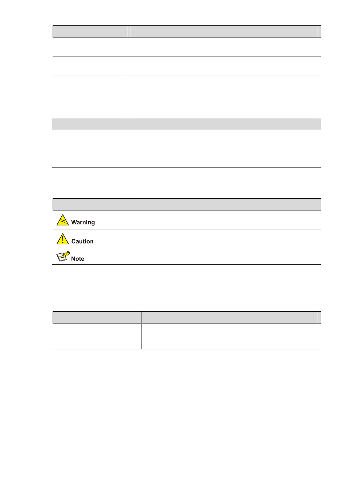
Symbols
Convention Description
Means reader be extremely careful. Improper operation may cause
bodily injury.
Related Documentation
In addition to this manual, each H3C SecPath Series Security Products documentation set includes the
following:
Manual Description
H3C SecPath Series Security
Products User Manual
Obtaining Documentation
You can access the most up-to-date H3C product documentation on the World Wide Web at this URL:
http://www.h3c.com.
The following are the columns from which you can obtain different categories of product docume ntation:
Means reader be careful. Improper operation may cause data loss or
damage to equipment.
Means a complementary description.
Describes the features, operation fundamentals, and configuration
commands of the H3C SecPath series security products, guides
you to make configuration, and provides configuration examples.
[Products & Solutions]: Provides information about products and technologies.
[Technical Support & Document > Technical Documents]: Provides several categories of product
documentation, such as installation, configuration, and maintenance.
[Technical Support & Document > Software Download]: Provides the documentation released with the
software version.
Page 5

Documentation Feedback
You can e-mail your comments about product documentation to info@h3c.com.
We appreciate your comments.
Environmental Protection
This product has been designed to comply with the requirements on environmental protection. For the
proper storage, use and disposal of this product, national laws and regulations must be ob served.
Page 6

Table of Contents
1 Product Overview······································································································································1-1
Introduction ·············································································································································1-1
Features ··········································································································································1-1
Physical Description································································································································1-2
U200-A ············································································································································1-2
U200-M············································································································································1-3
U200-S ············································································································································1-4
Technical Specifications··························································································································1-5
Processor and Storages··················································································································1-5
Dimensions and Weight···················································································································1-5
Fixed Interfaces and Slots···············································································································1-6
Power Input ·····································································································································1-6
Operating Environment Specifications ····························································································1-6
Components············································································································································1-7
Processor and Storages··················································································································1-7
Front Panel LEDs ····························································································································1-7
Fixed Interfaces ·······························································································································1-8
AC Power Input ·····························································································································1-14
Clock··············································································································································1-14
Port Lightning Arrester (Optional)··································································································1-14
Power Lightning Arrester (Optional) ······························································································1-15
Signal Lightning Arrester (Optional) ······························································································1-15
System Software ···························································································································1-16
i
Page 7

1 Product Overview
Introduction
The H3C SecPath U200 Series Unified Threat Management Products are new-generation UTM devices
designed for enterprise users.
The U200 series comprises three models:
z U200-A: Designed for large- and medium-sized enterprise users
z U200-M: Designed for medium-sized enterprise users
z U200-S: Designed for small- and medium-sized enterprise users
In addition to traditional firewall functions, the U200 series protect network security by providing a wide
range of functions including virtual firewall, security zone, intrusion detection and protection, gateway
anti-virus, anti-spam, P2P traffic control, and URL filtering. With the application specification packet filter
(ASPF) technology, a U200 series device can monitor connection setup processes and illegal
operations, and dynamically filter packets based on ACLs. Moreover, the U200 series support multiple
VPN services including IPSec VPN, L2TP VPN, and GRE VPN, and thereby can be used for
constructing a variety of VPN networks. The series deliver abundant routing capabilities and support
RIP and OSPF. Adopting a high-performance multi-core CPU, the U200-A, U200-M and U200-S can
support up to 10, 8, and 7 GE interfaces respectively, delivering high scalability for user investment
protection.
The U200 series are available with AC power supply to ensure high reliability, fully satisfy requirements
for network maintenance, update, and optimization, support detection of chassis internal temperature,
support network management, and provide a Web management interface.
The U200-A provides two MIM expansion slots for future service expansion. Currently, the slots support
the NSQ1GT2UA0 and NSQ1GP4U0 MIM modules.
The U200-M provides one MIM expansion slot and currently supports the same MIM as the U200-A
does.
The U200-S provides a mini expansion slot for future service expansion. Currently, the device supports
the 2-GE and NSQ1WLAN0 interface modules.
Features
The U200 series deliver the following features:
Powerful hardware platform
The U200 series perfectly fit in enterprise networks thanks to the adoption of MIPS64-based CPUs and
integrated high-performance hardware-based VPN accelerators.
Abundant security protection functions
z Security zone management: You can create security zones based on physical interfaces, logical
interfaces, Layer-2 Ethernet interfaces, or combinations of Layer-2 Ethernet interfaces and VLANs.
Interfaces belonging to the same security zone share the same security requirements in security
1-1
Page 8
policy control. With security zones, security administrators can classify interfaces with different
security requirements into different zones. This simplifies policy maintenance and separates
network services and security services.
z Packet filtering: Applies standard or extended ACL rules between security zones to implement
packet filtering based on UDP or TCP port information. You can also implement packet filtering
based on time ranges.
z Application specific packet filter (ASPF): Dynamically determines whether to forward or drop a
packet by checking its application layer protocol information (such as FTP, HTTP, SMTP, RTSP, or
any other application layer protocol carried on TCP/UDP), monitoring the status of
connection-oriented application layer protocols, and maintaining status information for each
connection.
z P2P traffic control: Performs in-depth packet inspection to identify and manipulate P2P traffic. With
various control policies, a U200 series device controls P2P traffic flexibly.
z Virtual firewall: You can create multiple virtual firewalls, each implementing a separate security
policy. These virtual firewalls are isolated from one another and thus can be managed separately.
z Diverse attack prevention functions: Guards against attacks including Land, Smurf, Fraggle,
WinNuke, Ping of Death, Tear Drop, IP Spoofing, IP fragment, fragment, TCP flag invalid, large
ICMP packet, IP Sweep, port scan, and DDoS attacks such as SYN Flood, UDP Flood, and ICMP
Flood.
z Packet filtering: Blocks specified URLs to better utilize network resources.
Powerful VPN functions
z IPSec and GRE
z IKE and PKI
z A built-in hardware-based VPN encryption engine, ensuring high-performance VPN processing
Physical Description
U200-A
Front view
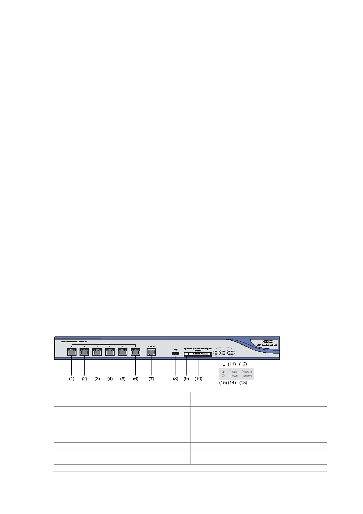
Figure 1-1 U200-A front view
(1) 10/100/1000 Mbps electrical Ethernet
interface 0
(3) 10/100/1000 Mbps electrical Ethernet
interface 2
(5) 10/100/1000 Mbps electrical Ethernet
interface 4
(7) Console port (CONSOLE) (8) USB interface
(9) CF card ejector button (10) CF card slot
(11) System LED (SYS) (12) Slot 2 LED (SLOT2)
(13) Slot 1 LED (SLOT1) (14) Power LED (PWR)
(15) CF card LED (CF)
(2) 10/100/1000 Mbps electrical Ethernet
interface 1
(4) 10/100/1000 Mbps electrical Ethernet
interface 3
(6) 10/100/1000 Mbps electrical Ethernet
interface 5
1-2
Page 9
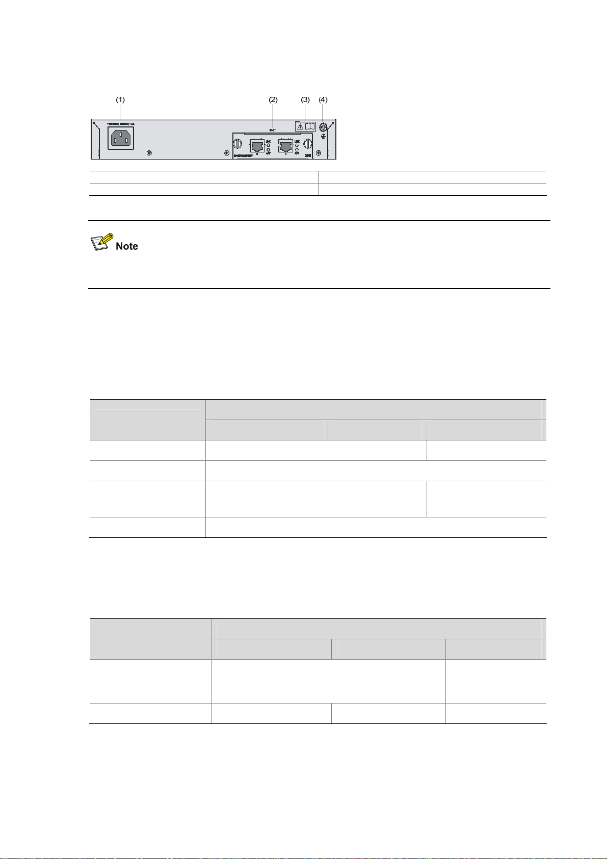
Rear view
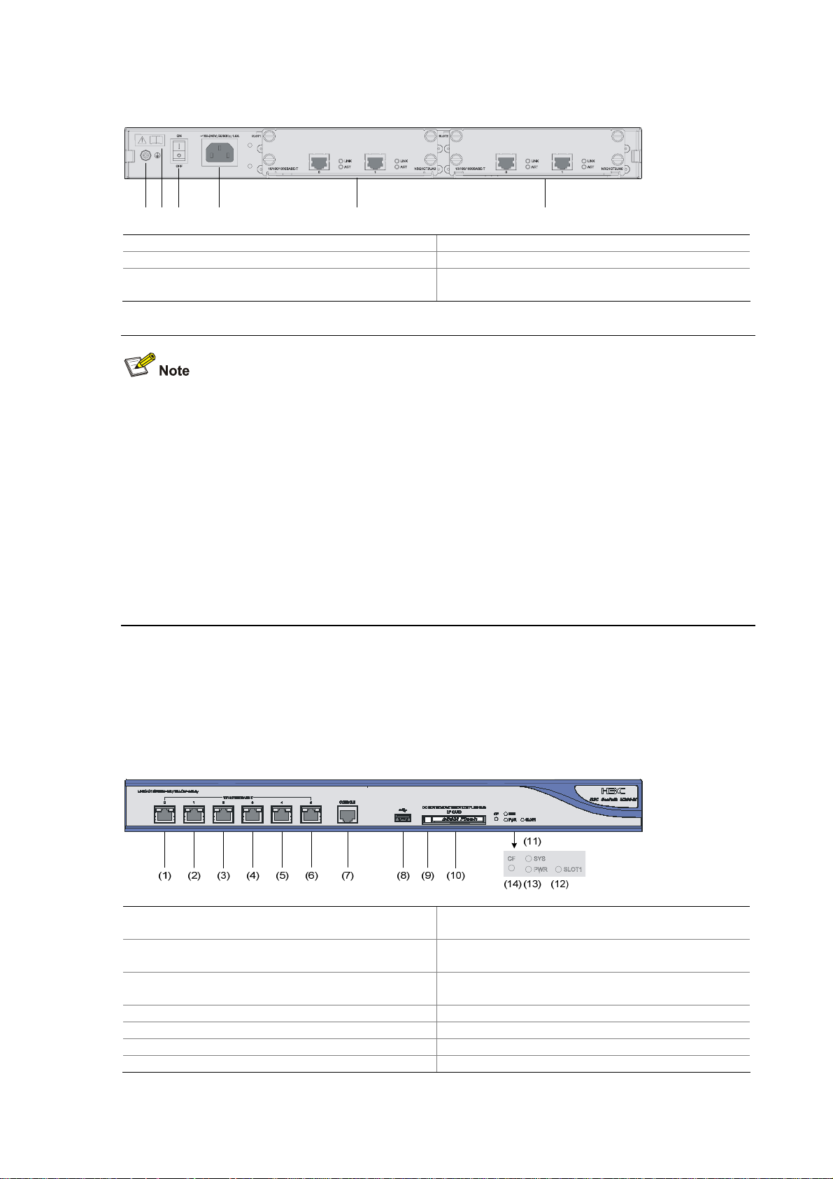
Figure 1-2 U200-A rear view
(1) (2) (3) (4) (5) (6)
(1) Grounding screw and symbol (2) OPEN BOOK symbol
(3) AC power switch (ON/OFF) (4) AC power socket
(5) Slot 1 (with an NSQ1GT2UA0 module
installed)
(6) Slot 2 (with an NSQ1GT2UA0 module
installed)
The open book symbol is used to remind the operator to read the relevant chapters when performing
any of these operations on the U200-A:
z Connecting the ESD-preventive wrist strap
z Installing the device on a workbench or in a rack
z Connecting the PGND cable or the AC power cord
z Connecting the power lightning arrester, signal lightning arrester, or port lightning arrester
z Connecting the console cable, AUX cable, or Ethernet cables
z Opening and closing the chassis cover
z Installing or removing the mini card (available only on the U200-S), MIM module (available only on
the U200-A and U200-M), or CF card
U200-M
Front view
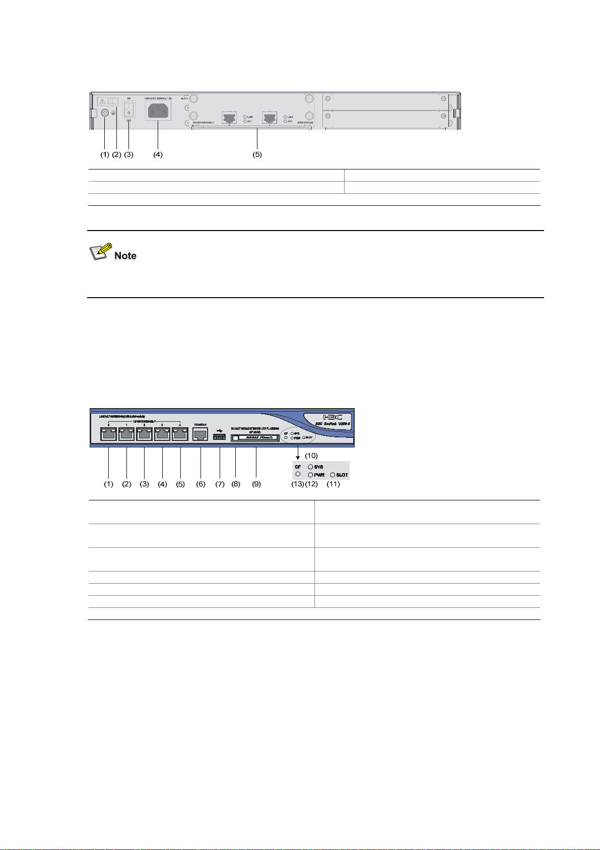
Figure 1-3 U200-M front view
(1) 10/100/1000 Mbps electrical Ethernet
interface 0
(3) 10/100/1000 Mbps electrical Ethernet
interface 2
(5) 10/100/1000 Mbps electrical Ethernet
interface 4
(7) Console port (CONSOLE) (8) USB interface
(9) CF card ejector button (10) CF card slot
(11) System LED (SYS) (12) Slot 1 LED (SLOT1)
(13) Power LED (PWR) (14) CF card LED (CF)
(2) 10/100/1000 Mbps electrical Ethernet
interface 1
(4) 10/100/1000 Mbps electrical Ethernet
interface 3
(6) 10/100/1000 Mbps electrical Ethernet
interface 5
1-3
Page 10
Rear view
Figure 1-4 U200-M rear view
(1) Grounding screw and symbol (2) OPEN BOOK symbol
(3) AC power switch (ON/OFF) (4) AC power socket
(5) Slot 1 (with an NSQ1GT2UA0 module installed)
For detailed description of the OPEN BOOK symbol, refer to the note under Figure 1-2.
U200-S
Front view
Figure 1-5 U200-S front view
(1) 10/100/1000 Mbps electrical Ethernet
interface 0
(3) 10/100/1000 Mbps electrical Ethernet
interface 2
(5) 10/100/1000 Mbps electrical Ethernet
interface 4
(7) USB interface (8) CF card ejector button
(9) CF card slot (10) System LED (SYS)
(11) Slot LED (SLOT) (12) Power LED (PWR)
(13) CF card LED (CF)
(2) 10/100/1000 Mbps electrical Ethernet
interface 1
(4) 10/100/1000 Mbps electrical Ethernet
interface 3
(6) Console port (CONSOLE)
1-4
Page 11
Rear view
Figure 1-6 U200-S rear view
(1) AC power socket (2) Slot (with 2GE)
(3) OPEN BOOK symbol (4) Grounding screw and sign
For detailed description of the open book symbol, refer to the note under Figure 1-2.
Technical Specifications
Processor and Storages
Table 1-1 Processor and storages of the U200 series
Item
Processor RMI XLS208 750 MHz RMI XLS404 800 MHz
Flash 32 MB
DDR2 SDRAM
Memory type and size
External CF card 256 MB, 512 MB, or 1 GB
Dimensions and Weight
Table 1-2 Dimensions and weight of the U200 series
1 GB by default
Description
U200-A U200-M U200-S
DDR2 SDRAM
512 MB by default
Item
U200-A U200-M U200-S
Dimensions (H × W × D),
excluding feet and
mounting brackets
Weight (fully configured) 5.9 kg (13.01 lb) 5.5 kg (12.13 lb) 2.22 kg (4.89 lb)
44.2 × 442 × 400 mm (1.74 × 17.40 × 15.75 in.)
1-5
Description
43.6 × 300 × 260
mm (1.72 × 11.81 ×
10.24 in.)
Page 12

Fixed Interfaces and Slots
Table 1-3 Interface (fixed) and slot specifications
Item
Console port 1 (9600 bps to 115200 bps, 9600 bps by default)
USB
interface
GE
interfaces
CF card slot 1 external CF card slot (256 MB, 512 MB, or 1 GB)
Slots
Power Input
Table 1-4 Input voltage specifications
Description
U200-A U200-M U200-S
1 (host mode, reserved without software support)
6 (GE0 to GE5) 5 (GE0 to GE4)
10/100/1000 Mbps electrical interfaces, MDI/MDIX autosensing
2 MIM expansion slots
Available interface module:
NSQ1GT2UA0 and
NSQ1GP4U0
Item
U200-A U200-M U200-S
1 MIM expansion slot
Available interface module:
NSQ1GT2UA0 and
NSQ1GP4U0
Description
1 Mini expansion slot
Available interface
module: 2GE and
NSQ1WLAN0
Rated voltage range
Maximum input current
Maximum power
100 VAC to 240 VAC; 50 Hz or 60 Hz
1.6 A 0.6 A
100 W 54 W
Operating Environment Specifications
Table 1-5 Operating environment specifications
Item
U200-A U200-M U200-S
Operating temperature 0°C to 45°C (32°F to 113°F)
Operating humidity
(noncondensing)
Operating altitude
10% to 95%
–60 to 3000 m (–196.85 to +9842.52 ft.)
Description
–60 to 2000 m (–196.85
to +6561.68 ft.)
1-6
Page 13
Components
Processor and Storages
Processor
A U200 series device uses a multi-core microprocessor as its data forwarding and service processing
engine.
Flash
A U200 series device uses a 32 MB flash for storing BootWare and APP.
Memory
The memory temporarily stores data for the running system and buffering data to be forwarded. By
default, the U200-A and U200-M are equipped with a 1 GB memory while the U200-S has a 512 MB
memory.
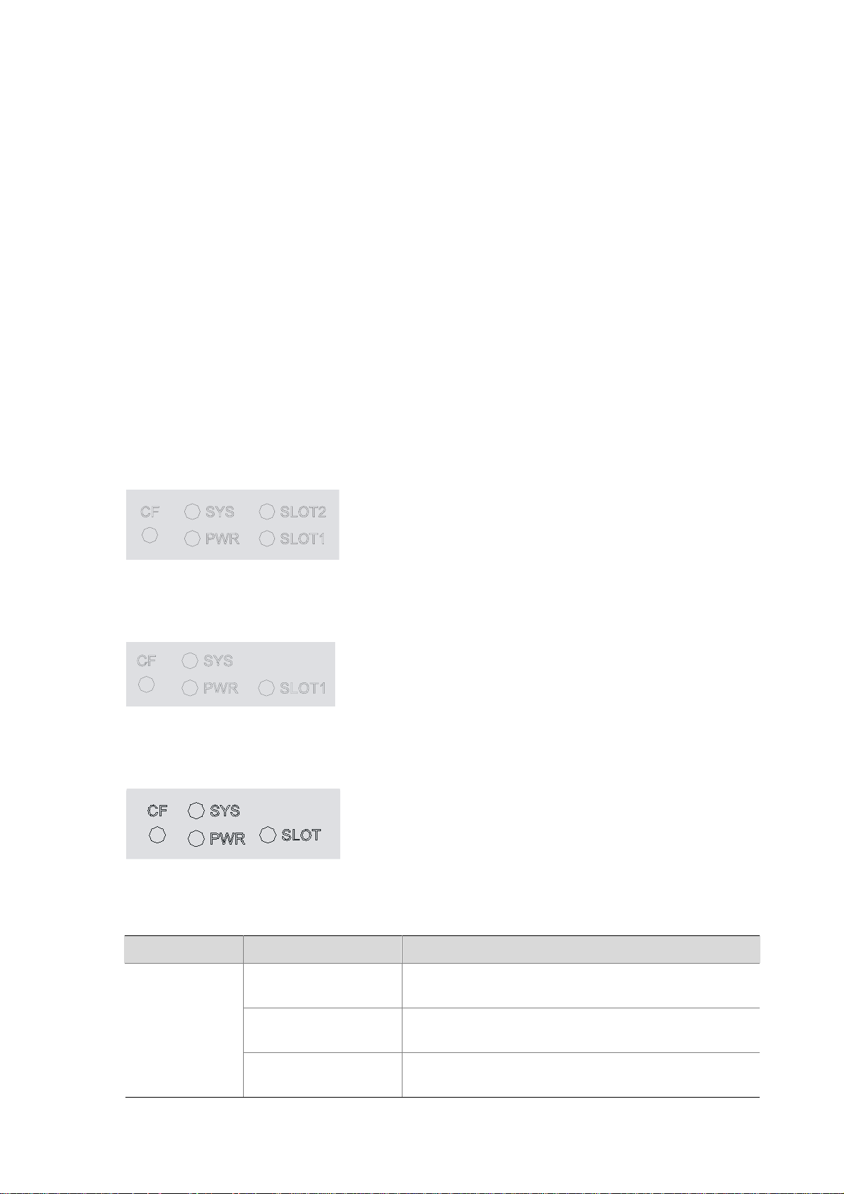
Front Panel LEDs
Figure 1-7 U200-A front panel LEDs
Figure 1-8 U200-M front panel LEDs
Figure 1-9 U200-S front panel LEDs
Table 1-6 Description of the front panel LEDs
LED Status Description
Off
CF (green)
On
Blinking
No CF card is in position or the CF card cannot be
identified.
A CF card is in position and has passed the test. It can
be removed in this state.
The system is accessing the CF card. Do not unplug
the card in this state.
1-7
Page 14

LED Status Description
SYS (green)
PWR (green)
SLOT1/SLOT2/
SLOT (green)
Fixed Interfaces
Table 1-7 Description of the fixed interfaces
Interface Description
Console port 1
Off The system is powered off or faulty.
Slow blinking (at 1 Hz)
The interface module is operating normally as
configured.
Fast blinking (at 8 Hz) Software is being loaded or the system is not working.
Off The power module is not working or faulty.
On The power module is supplying power normally.
Off
On
No interface module is in the slot or the interface
module is faulty.
An interface module is in the slot and operating
normally.
USB interface 1 Host mode, reserved without software support
U200-A 6 10/100/1000 Mbps electrical Ethernet interfaces: GE0 to GE5
GE
interfaces
U200-M 6 10/100/1000 Mbps electrical Ethernet interfaces: GE0 to GE5
U200-S 5 10/100/1000 Mbps electrical Ethernet interfaces: GE0 to GE4
Three CF card options of different memory sizes are available:
CF card slot 1
z 256 MB
z 512 MB
z 1 GB
Console port
1) Introduction
A U200 series device provides an RS232 asynchronous serial console port (Console), which can be
connected to a computer for system debugging, configuration, maintenance, management, and
software loading.
2) Specifications
Table 1-8 Technical specification of the console port
Attribute Description
Connector type
Interface standard
Baud rate
Maximum transmission distance
RJ-45
Asynchronous EIA/TIA-232
9600 bps (default) to 115200 bps
15 m (49.21 ft.)
1-8
Page 15
Attribute Description
Connection to an ASCII terminal
Services
Connection to the serial interface of a local PC to run the
terminal emulation program
Command line interface
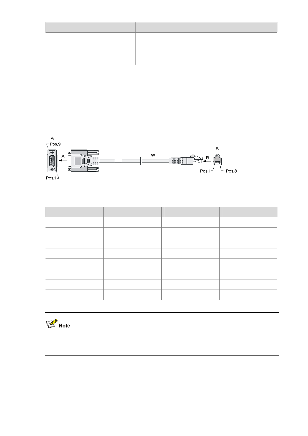
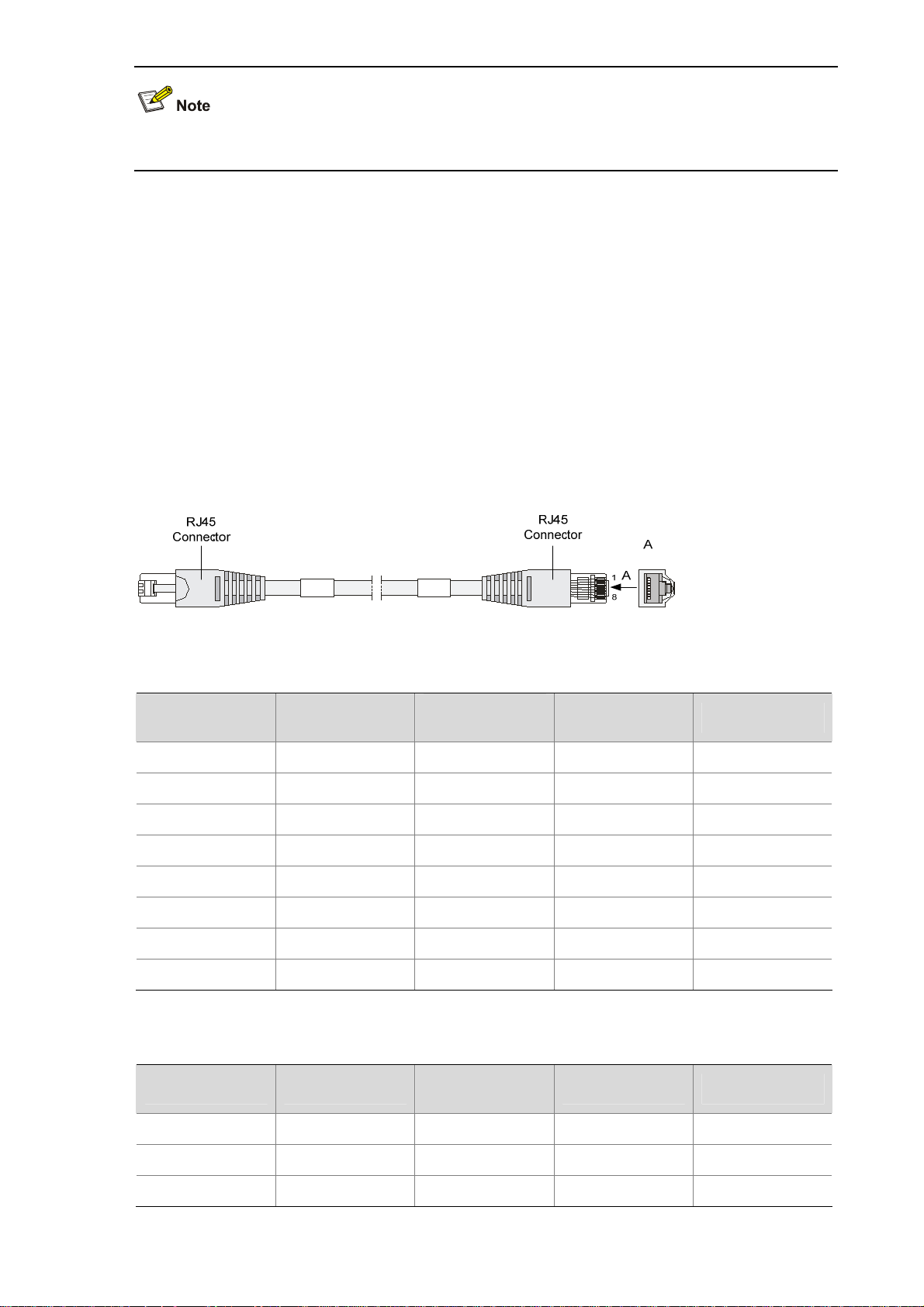
3) Console cable
The console cable is an 8-core shielded cable. The RJ-45 connector at one end of the cable is for the
console port on the UTM device, and the DB-9 female connector at the other end is for the serial port on
a configuration terminal.
Figure 1-10 illustrates the console cable.
Figure 1-10 Console cable
Table 1-9 Console cable pinouts
RJ-45 Signal direction DB9 Signal
1
2
3
4
Æ
Æ
Æ
Å
8 CTS
6 DSR
2 RXD
1 DCD
5 — 5 GND
6
7
8
Å
Å
Å
3 TXD
4 DTR
7 RTS
For how to connect the console cable, refer to the “Connecting the Console Cable” section in Chapter 4
“Installing the U200 Series Device.”
Ethernet interfaces
1) Introduction
A UTM series device provides fixed 10/100/1000Base-T Ethernet interfaces on its front panel, the
number of which depends on the device model. Each fixed Ethernet interface (RJ-45) uses two built-in
1-9
Page 16
LEDs in the upper corners to indicate its status.
Table 1-10 Description of Ethernet interface LEDs
Status Description
LINK
Off No link is present.
On A link is present.
Off No data is being received or transmitted.
ACT
Blinking Data is being received or transmitted.
2) Specifications
Table 1-11 Technical specifications of the Ethernet interfaces
Item Description
Connector type RJ-45
Interface type
Frame format
Rate and negotiation
mode
Autosensing (Ethernet does not support MDI/MDIX autosensing when
working in the forced mode)
Ethernet_II
Ethernet_SNAP
10 Mbps (autosensing)
100 Mbps (autosensing)
1000 Mbps (autosensing)
Half-/full-duplex auto-negotiation
Half-/full-duplex auto-negotiation
Full-duplex auto-negotiation
The media dependent interface (MDI) standard is typically used for the Ethernet interfaces of network
adaptors. The media dependent interface crossover (MDI-X) standard is typically used on hubs or LAN
switches.
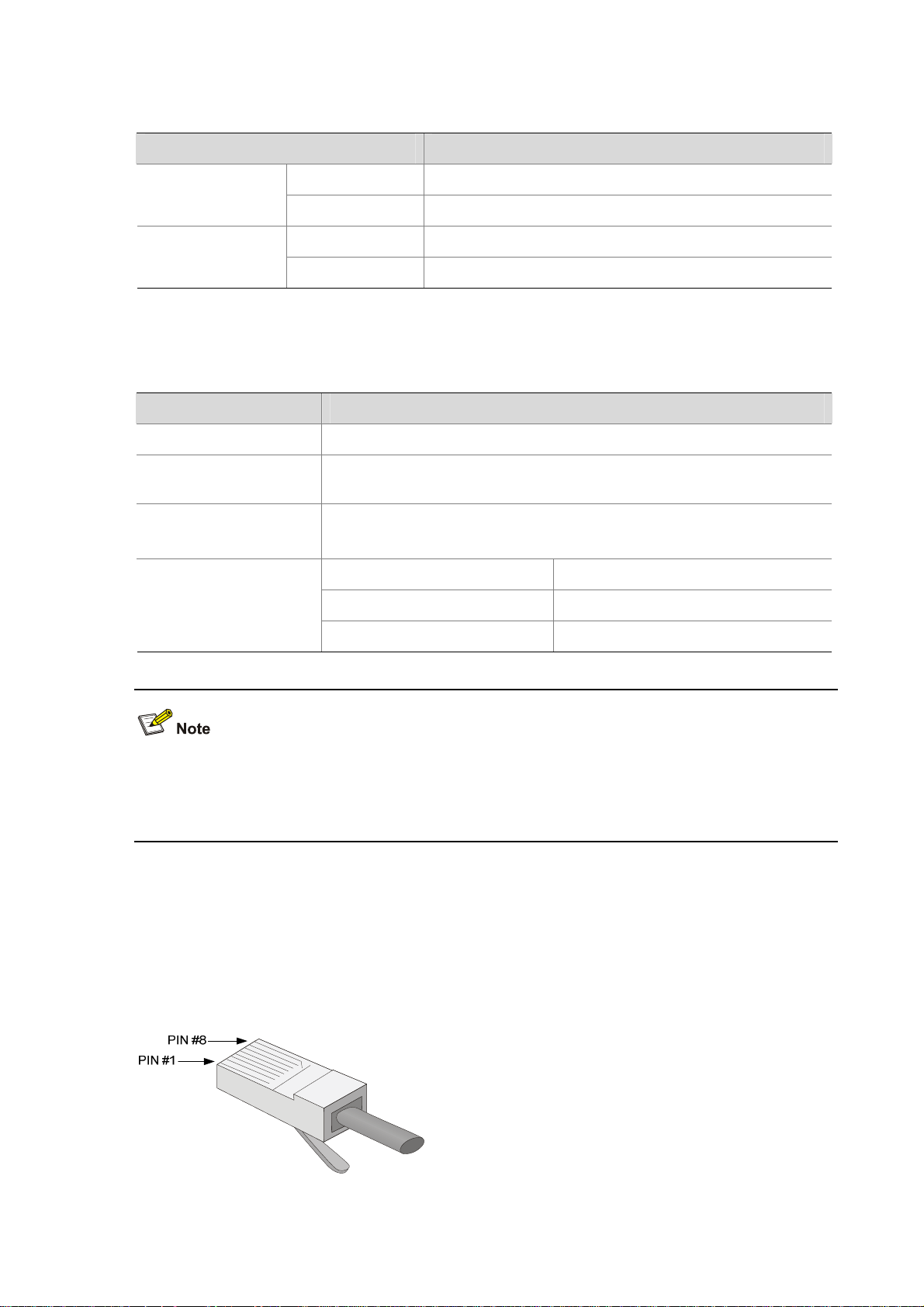
3) RJ-45 connector
The 10/100/1000Base-T Ethernet interfaces of the U200 series use RJ-45 connectors and support
MDI/MDIX autosensing. Category-5 twisted pair cables are used for RJ-45 connectors.
Figure 1-11
shows an RJ-45 connector.
Figure 1-11 RJ-45 connector
1-10
Page 17
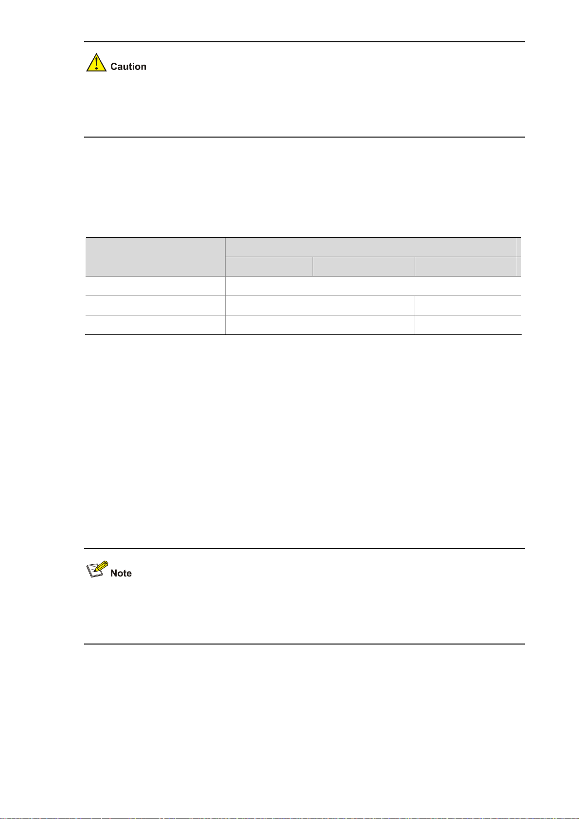
When working in the forced mode, Ethernet does not support MDI/MDIX autosensing.
4) Cable connecting electrical Ethernet interfaces
Ethernet electrical interfaces usually use category-5 twisted pair cables. Ethernet cables fall into two
categories:
z Standard cables: Also known as straight-through cables. At both ends of a standard cable, wires
are crimped in the RJ-45 connectors in the same sequence. A straight-through cable is used for
connecting a terminal (for example, a PC or UTM device) to a hub or LAN switch. Straight-through
cables are shipped with the U200 series.
z Crossover cables: At both ends of a crossover cable, wires are crimped in the RJ-45 connectors in
different sequences. A crossover cable is used for connecting two terminals (for example, two PCs
or UTM devices). You can make crossover cables yourself as needed.
Figure 1-12 Ethernet cable
Table 1-12 Straight-through cable connector pinouts
RJ-45 Signal
Category-5
twisted pair
1 TX+ White (Orange)
2 TX- Orange
3 RX+
White (Green)
4 — Blue
5 — White (Blue)
6 RX- Green
7 — White (Brown)
8 — Brown
Table 1-13 Crossover cable connector pinouts
Signal direction RJ-45
Æ
Å
1
2
3
Æ
— 4
— 5
Å
— 7
6
— 8
RJ-45 Signal direction
1 TX+ White (Orange)
2 TX- Orange
3 RX+ White (Green)
Category-5
twisted pair
1-11
Signal direction RJ45
Æ
Æ
Å
3
6
1
Page 18

RJ-45 Signal direction
Category-5
twisted pair
Signal direction RJ45
4 — Blue — 4
5 — White (Blue) — 5
6 RX- Green
Å
2
7 — White (Brown) — 7
8 — Brown — 8
z You can refer to the tables above when trying to identify or preparing the two types of Ethernet
cables.
z When preparing Ethernet cables, follow the color pairings in the tables. Otherwise, communication
quality will be affected even if the two devices at both ends can communicate.
z When preparing Ethernet cables, use shielded cables preferentially for electromagnetic
compatibility.
USB interface
USB interfaces can connect multiple types of devices and provide higher data transfer rates than
common parallel interfaces and serial interfaces.
The U200 series support USB 2.0 to provide important storage and security functions. For example,
with USB interfaces, you can provide large flash memory space for application programs, configuration
files, and VPN certificates for setting up secure VPN connections and, secure distribution of
configuration files.
In addition, USB interfaces provide a backup CF card mechanism to make file backup and restoration
easy and reliable.
Figure 1-13 USB interface
The USB interface provided by a U200 series device is a USB 2.0 type-A interface. Serving as a host, it
can connect an external USB device to expand the device's storage space for storing files and logs and
in addition, facilitate file transfer.
1-12
Page 19
z At present, the USB interface provided on a U200 series device is a reserved module without
software support.
z Use the USB flash drives provided by H3C only, because the U200 series may be incompatible
with other USB flash drives.
z Avoid removing the USB flash drive when its LED is flashing. Doing so may cause the file system
on the drive to get corrupted.
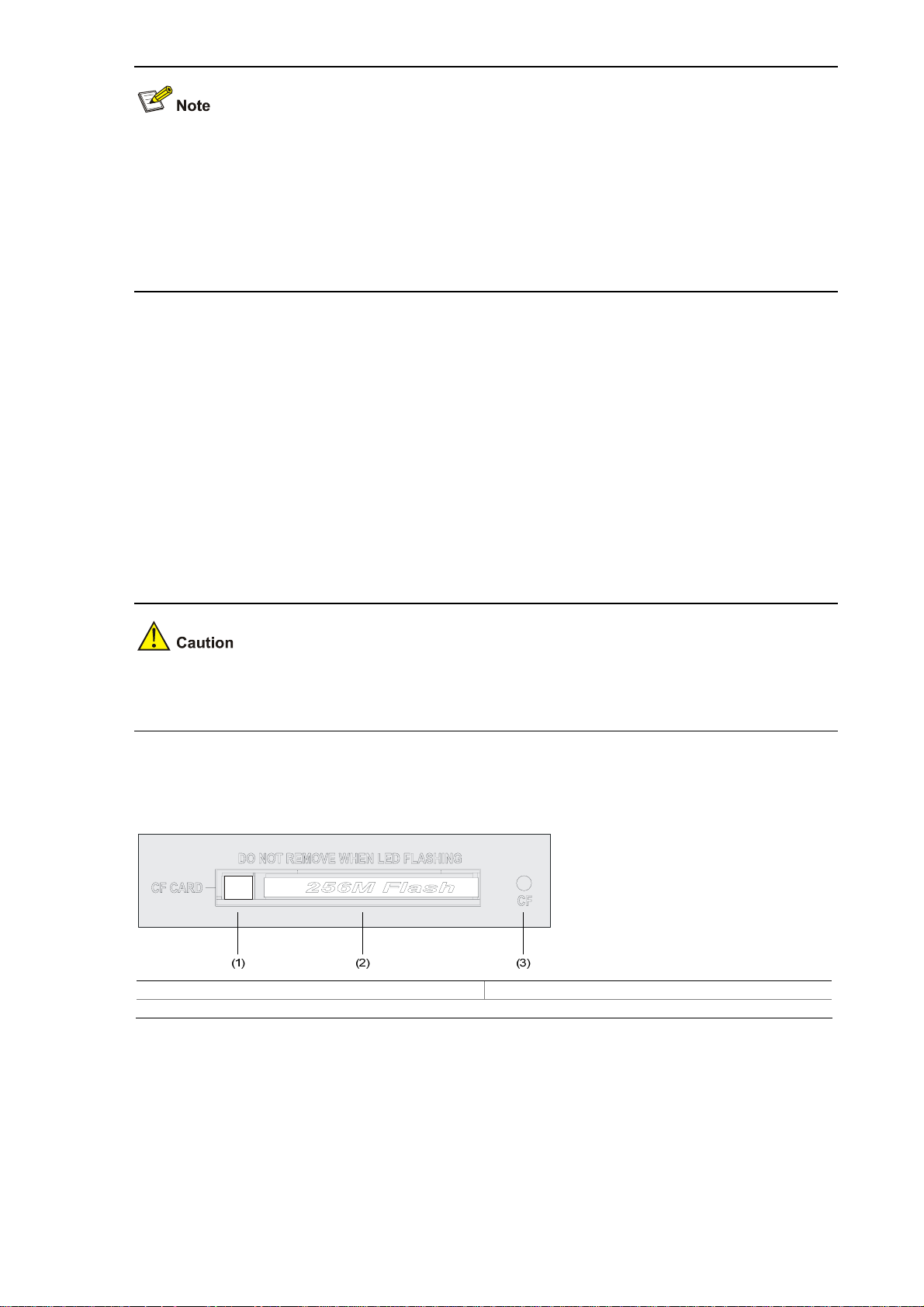
CF card
1) Introduction
A compact flash (CF) card is used for storing logs, host files, and configuration files.
A U200 series device provides an external CF card slot for expanding storage space.
Three CF card options of different memory sizes are available:
z 256 MB
z 512 MB
z 1 GB
Use the CF cards provided by H3C only, because the U200 series may be incompatible with other CF
cards.
2) CF card slot
Figure 1-14 CF card
(1) Ejector button (2) CF card slot
(3) CF card LED (CF)
3) CF card LED
For description of the CF card LED, see
Table 1-6.
1-13
Page 20
The CF card is hot-swappable. When the device is reading from or writing to the CF card or performing
any other file system related operation, the CF card LED blinks. Do not unplug the CF card in this state
because doing so can corrupt the file system in it.
AC Power Input
Table 1-14 lists the AC power specifications for the U200 series.
Table 1-14 AC power specifications
Clock
Item
Description
U200-A U200-M U200-S
Rated voltage range
Maximum input current
Maximum power
100 VAC to 240 VAC; 50 Hz or 60 Hz
1.6 A
100 W 54 W
0.6 A
The U200 series are designed with a clock module for providing system time. You can set the system
time at the command line interface.
The clock module can work despite power failure to ensure that the system time is correct at reboot.
With the device powered off, the clock module can work for at least 10 years.
Note that:
z Never replace the clock module battery when power is present on the device.
z The system time gets lost once the clock module battery is removed. You can set it at the
command line interface.
You can use three commands including clock datetime, ock summer-time one-off (or clock
summer-time repeating), and clock timezone to complete setting the system time. See the
accompanying documentation for how to do that.
Port Lightning Arrester (Optional)
Before connecting an outdoor Ethernet cable to an Ethernet port, install a port lightning arrester to
protect the device against lightning strikes.
The port lightning arresters available for the U200 series feature these:
1-14
Page 21

z For single-port use, maximum discharge current (8/20μs waveform): 5 kA, output voltage
(10/700μs waveform): core-core < 40 V, core-ground < 600 V.
For the installation of the port lightning arrester, refer to the “Installing a Port Lightning Arrester” section
in Chapter 4 “Installing the U200 Series Device.”
Power Lightning Arrester (Optional)
Before connecting an outdoor AC power cable to the device directly, you can connect the AC power
input to a lightning protection busbar to protect the device against lightning strikes. In a heavy lightning
area, you are recommended to install a power lightning arrester.
The lightning arresters available for the U200 series feature these:
z Maximum discharge current of 6500 A, protection for 500 VAC to 220 VAC.
For how to install a power lightning arrester, refer to the “Installing a Power Lightning Arrester
(Optional)” section in Chapter 4 “Installing the U200 Series Device.”
Signal Lightning Arrester (Optional)
Generally, you need to install a signal lightning arrester between a signal cable and the connected
device. This can protect electronic components against surge over-voltage resulting from lightning
strikes or any other interferences, and minimize the impact on the system.
The following are specifications of the three signal lightning arrester options available for the U200
series:
z Maximum discharge current 2.5KA/protection voltage 25V-SMB-75J/SMB-75J-1W-10Mbps.
z Maximum discharge current 2.5KA/protection voltage 25V-BNC-75K/BNC-75K-10MBit/s.
z For U-shape ports, maximum discharge current 3KA/common mode 400 V/differential mode
170V-RJ11
For how to install a signal lightning arrester, refer to the “Installing a Signal Lightning Arrester” section in
Chapter 4 “Installing the U200 Series Device.“
1-15
Page 22

System Software
The U200 series operate on the H3C Comware V5 or i-Ware software platform, integrating a rich set of
security features including virtual firewall, attack prevention, load balancing, and P2P traffic
management. Combining network and security technologies perfectly, the series can be deployed in
various complex network environments to provide strong security protection.
1-16
Page 23

Table of Contents
2 Interface Cards and Interface Modules ···································································································2-1
2GE Module ············································································································································2-1
NSQ1GT2UA0 Module····························································································································2-3
NSQ1GP4U0 Module······························································································································2-4
NSQ1WLAN0 Module ·····························································································································2-6
Arranging Slots and Naming Interfaces ··································································································2-7
Slot Arrangement·····························································································································2-7
Naming Interfaces ···························································································································2-7
Examples·········································································································································2-7
i
Page 24

2 Interface Cards and Interface Modules
z Currently, the U200 series do not support hot-swapping of interface modules.
z With the hot swapping feature, you can remove an interface module after stopping it with the
remove slot number command and then replacing the interface module or plugging in a new
interface module as needed without powering off the device.
z Currently the 2GE and NSQ1GT2UA0 interface modules are not available yet.
2GE Module
Introduction
The 2GE module is a mini high-speed Layer 3 Gigabit Ethernet interface module. The 2GE module
provides two RJ-45 electrical interfaces that support the Layer 3 routing function. Each interface on the
2GE module is available with a link LED and an activity LED for monitoring the link status and data
transmission status. The 2GE module is connected to the processor through a 10-Gbps high-speed bus
and can provide all functions of Layer 3 Ethernet interfaces with high performance.
Front view
Figure 2-1 2GE front view
(1) Captive screw (2) GE interface 0
(3) Link LED (LINK) of GE interface 0 (4) GE interface 1
(5) Link LED (LINK) of GE interface 1
(7) Data transmit/receive activity LED of GE interface 0 (ACT)
(6) Data transmit/receive activity LED of GE interface 1
(ACT)
2-1
Page 25
LEDs
Table 2-1 Description of the LEDs on the front panel of the 2GE module
LED Status Description
LINK
Off No link is present.
On
Off No data is being transmitted or received.
ACT
Blinking Data is being transmitted or received.
Interface specifications
Table 2-2 Interface specifications of 2GE
Item Description
Connector type
Number of interfaces
Interface standards
RJ-45
2
802.3, 802.3u, 802.3ab
Autosensing
Interface type
When working in the forced mode, Ethernet does not support
MDI/MDIX autosensing.
Frame formats
Ethernet_II
Ethernet_SNAP
A link is present.
Maximum transmission
distance
Rate and negotiation mode
100 m (328.08 ft.) over category-5 twisted pairs
10 Mbps (autosensing)
100 Mbps (autosensing)
1000 Mbps (autosensing)
Half-/full-duplex auto-negotiation
Half-/full-duplex auto-negotiation
Full-duplex auto-negotiation
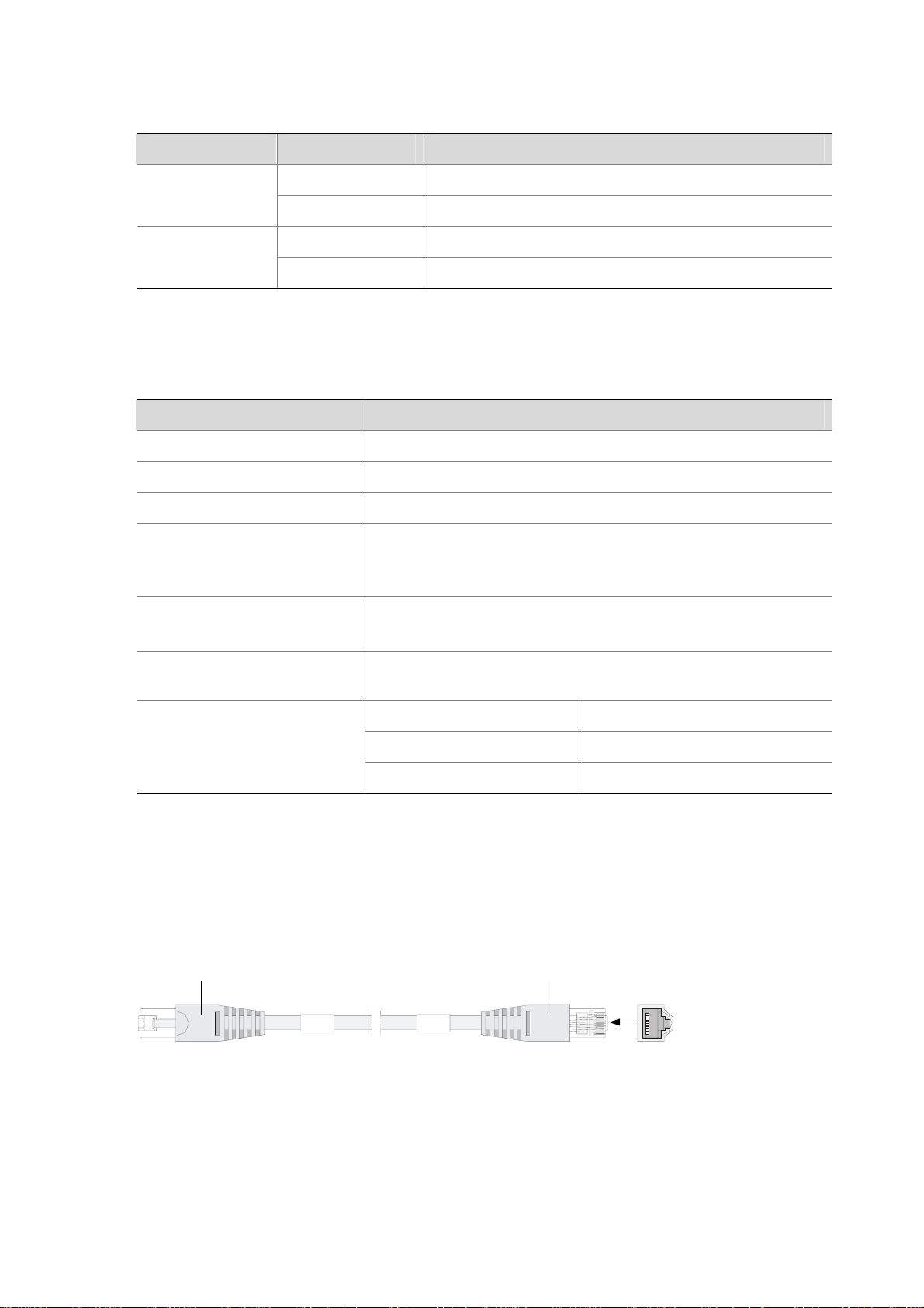
Interface cable
The 2GE module uses a straight-through or crossover Ethernet cable for connection.
Figure 2-2 Ethernet cable
RJ-45
Connector
RJ-45
Connector
A
1
A
8
2-2
Page 26
For how to connect the Ethernet cable, refer to the “Connecting an Ethernet cable for the 2GE module”
section in Chapter 4 “Installing the U200 Series Device.”
NSQ1GT2UA0 Module
Introduction
The NSQ1GT2UA0 module is a MIM high-speed Layer 3 Gigabit Ethernet interface module. The
module provides two RJ-45 electrical interfaces that support the Layer-3 routing function. Each
interface on the NSQ1GT2UA0 module is available with a link LED and an activity LED for monitoring
the link status and data transmission status. The NSQ1GT2UA0 module is connected to the processor
through a PCIE high-speed bus to provide all functions of a Layer-3 Ethernet interface with high
performance.
Front view
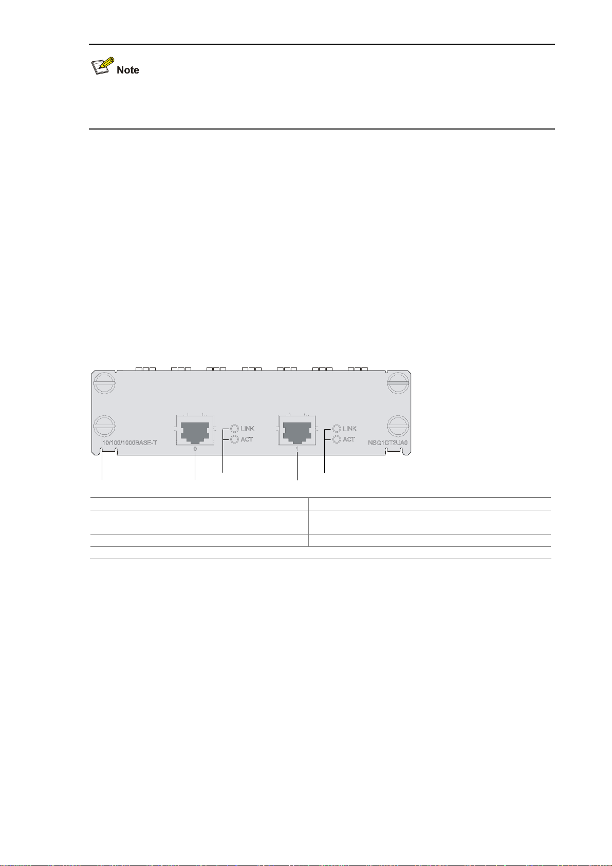
Figure 2-3 NSQ1GT2UA0 front view
(1) (2) (5)
(3)
(4)
(6)
(7)
(1) Captive screw (2) GE interface 0
(3) Link LED (LINK) of GE interface 0
(4) Data transmit/receive activity LED (ACT) of GE
interface 0
(5) GE interface 1 (6) Link LED (LINK) of GE interface 1
(7) Data transmit/receive activity LED (ACT) of GE interface 1
LEDs
See Table 2-1.
Interface specifications
See Table 2-2.
Interface cable
See Figure 2-2.
2-3
Page 27
NSQ1GP4U0 Module
Introduction
The NSQ1GP4U0 module is a high-speed Layer 3 Gigabit Ethernet interface module. The module
provides four SFP optical interfaces that support the Layer-3 routing function. Each interface on the
NSQ1GP4U0 module is available with an LED indicating its status. The NSQ1GP4U0 module is
connected to the processor through a PCIE high-speed bus to provide all functions of a Layer-3
Ethernet interface with high performance.
Front view
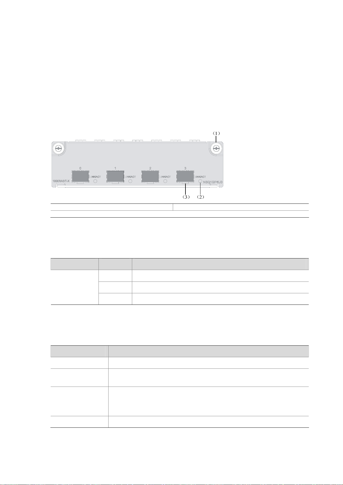
Figure 2-4 NSQ1GP4U0 front view
(1) Captive screw (2) LINK/ACT LED
(3) SFP interface
LEDs
Table 2-3 Description of LEDs on the front panel of NSQ1GP4U0
LED Status Meaning
Off No link is present on the interface.
LINK/ACT
(Green)
On A 1000 Mbps link is present on the SFP interface.
Blinking The SFP interface is transmitting or receiving data at 1000 Mbps.
Interface specifications
Table 2-4 Interface specifications of NSQ1GP4U0
Item Specification
Connector type SFP/LC
Number of
interfaces
Interface standards
Interface speed 1000 Mbps
4
802.3, 802.3u, and 802.3ab
Ethernet_II
Ethernet_SNAP
2-4
Page 28
Item Specification
Single-mode
ultra-long
haul
Optical
Type
Multi-mode
short haul
Single-mode
medium haul
Long haul
(1310 nm)
Long haul
(1550 nm)
transmit
power
Min. –9.5 dBm –9 dBm –2 dBm –4 dBm –4 dBm
Max. 0 dBm –3 dBm 5 dBm 1 dBm 2 dBm
Receiving
sensitivity
–17 dBm –20 dBm –23 dBm –21 dBm –22 dBm
Central wavelength 850 nm 1310 nm 1310 nm 1550 nm 1550 nm
Max. transmission
distance
Fiber type
0.55 km
(0.34 miles)
62.5/125 μm
multi-mode
10 km (6.21
miles)
9/125 μm
single-mode
40 km (24.86
miles)
9/125 μm
single-mode
40 km (24.86
miles)
9/125 μm
single-mode
70 km (43.50
miles)
9/125 μm
single-mode
Interface cable
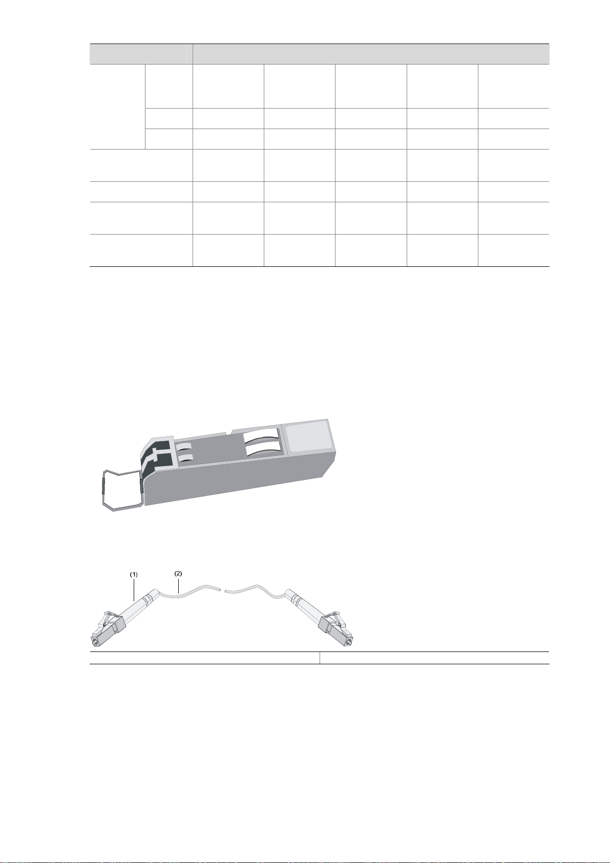
z The NSQ1GP4U0 module can work with SFP optical transceivers using optical fibers with LC-type
connectors.
Figure 2-5 and Figure 2-6 show an SFP optical transceiver and an optical fiber with LC-type connectors
respectively.
Figure 2-5 SFP optical transceiver
Figure 2-6 Optical fiber with LC connectors
(1) LC-type connector (2) Optical fiber
z The NSQ1GP4U0 module can work with optical-to-electrical SFP modules using straight-through
or crossover Ethernet cables. See
Figure 2-2.
2-5
Page 29

For how to connect the interface cable for the NSQ1GP4U0 module, refer to “Connecting an optical
fiber or Ethernet cable to the NSQ1GP4U0 module" in Chapter 4 “Installing the U200 Series Device.”
NSQ1WLAN0 Module
Introduction
The NSQ1WLAN0 module is an 802.11a/b/g mini WLAN interface module that supports the Layer-3
routing function. The NSQ1WLAN0 module is connected to the processor through a 10-Gbps
high-speed bus to provide all functions of a Layer-3 Ethernet interface with high performance.
Front view
Figure 2-7 NSQ1WLAN0 front view
(1) Captive screw (2) Auxiliary antenna interface
(3) Main antenna interface
Interface specifications
Table 2-5 Interface specifications of NSQ1GP4U0
Item Specification
Interface type Antenna interface (2.4 GHz or 5 GHz)
Number of interfaces 1
Interface standards IEEE 802.11a, IEEE 802.11b, IEEE 802.11g
6, 9, 12, 18, 24, 36, 48, 54 MHz 802.11a
Interface speed and negotiation
mode
1, 2, 5.5, 11 MHz 802.11b
6, 9, 12, 18, 24, 36, 48, 54 MHz 802.11g
Interface cable
The antenna interface of the NSQ1WLAN0 module supports 2.4 GHz and 5 GHz dual-frequency omni
antennas.
2-6
Page 30

Figure 2-8 Omni antenna for the NSQ1WLAN0 module
For how to connect the antenna for the NSQ1WLAN0 module, refer to “Connecting an antenna for the
NSQ1WLAN0 module” in Chapter 4 “Installing the U200 Series Device.”
Arranging Slots and Naming Interfaces
Slot Arrangement
The U200 series support interfaces such as console, AUX, Gigabit Ethernet, and WLAN interfaces. This
section describes how these interfaces are numbered.
Naming Interfaces
The interfaces on a U200 series device are named following these conventions:
1) An interface is named in the form of interface-type X/Y, where
z interface-type represents the type of the interface, such as GigabitEthernet.
z X represents the number of the slot in which the interface module is inserted.
z Y represents the number of the interface on the interface module.
2) The interfaces on the same interface module uses the same slot number X.
3) The interfaces of the same type on an interface module are numbered starting with 0 for Y from left
to right.
Examples
1) The five fixed GigabitEthernet interfaces on the U200-S are named as follows:
z GigabitEthernet 0/0
z GigabitEthernet 0/1
z GigabitEthernet 0/2
z GigabitEthernet 0/3
z GigabitEthernet 0/4
2) If a 2GE module is installed on the U200-S, the GigabitEthernet interfaces on the 2GE module are
numbered as follows:
z GigabitEthernet 1/0
z GigabitEthernet 1/1
2-7
Page 31

3) If an NSQ1WLAN0 module is installed on the U200-S, the WLAN interface on the module is named
as follows:
z Wlan Radio 1/0
2-8
Page 32

Table of Contents
3 Preparing for Installation ··························································································································3-1
Environment Requirements ····················································································································3-1
Ventilation Requirements ················································································································3-1
Temperature and Humidity Requirements ······················································································3-1
Cleanness Requirements ················································································································3-2
Electrostatic Discharge Prevention ·································································································3-2
Electromagnetic Interference Prevention ························································································3-3
Lightning Protection·························································································································3-4
Workbench Requirements···············································································································3-4
Rack-Mounting Requirements·········································································································3-4
Safety Precautions ··································································································································3-4
Safety Signs ····································································································································3-4
General Safety Recommendations ·································································································3-5
Electricity Safety ······························································································································3-5
Installation Tools, Meters and Devices ···································································································3-5
Installation Accessories Supplied with a U200 Series Device ························································3-5
User supplied tools ··························································································································3-5
Reference ········································································································································3-5
Checklist Before Installation····················································································································3-6
i
Page 33

3 Preparing for Installation
Environment Requirements
The U200 series are designed for indoor use. To ensure normal operation and prolong service life of the
U200 series devices, the installation site must meet the requirements described in this chapter.
Ventilation Requirements
The fans of a U200 series device draw air in through the inlet vents on the left and out through the
exhaust vents on the right. Take the U200-S as an example.
Figure 3-1 Air flow design of the U200 series
Make sure that:
There is at least 10 cm (3.94 in.) of clearance around the air intake and the air exhaust for heat
dissipation of the chassis.
A ventilation system is available at the installation site.
Temperature and Humidity Requirements
The equipment room must maintain proper humidity to prevent poor insulation, electricity creepage and
corrosion accompanying high humidity, and to prevent washer contraction and electrostatic discharge
accompanying low humidity. In dry environments where relative humidity is very low, electrostatic
discharge (ESD) is more likely to happen causing the complementary metal-oxide-semiconductor
(CMOS) circuitry to fail.
A proper temperature condition must also be maintained to prevent premature material aging and
degraded reliability accompanying high temperature conditions.
Table 3-1 lists the temperature and humidity requirements.
Table 3-1 Temperature and humidity requirements in the equipment room
Temperature Relative humidity
0°C to 45°C (32°F to 113°F) 10% to 95% (noncondensing)
3-1
Page 34

Cleanness Requirements
Dust concentration limits
Dust is hazardous to the operating safety of devices. Dust buildup on chassis may result in static
absorption, causing poor contact of metal components or points. When indoor humidity is extremely low,
this is more likely to happen, shortening the useful life of the devices and causing communication
failures.
Table 3-2 lists the dust concentration limits in the equipment room.
Table 3-2 Dust concentration limits in the equipment room
Diameter (μm) 0.5 1 3 5
Concentration
limit (particles/m
3
)
1.4 × 10
7
7 × 10⁵ 2.4 × 10⁵ 1.3 × 10⁵
Harmful gas concentration limits
Besides, the equipment room should meet the rigorous limits on salt, acid and sulfide to eliminate
corrosion and premature aging of some parts, as shown
Table 3-3 Harmful gas concentration limits
Gas Max (mg/m3)
SO2 0.2
H2S 0.006
NH3 0.05
Cl2 0.01
Electrostatic Discharge Prevention
Table 3-3.
Sources and damages of static electricity
By design, a U200 series device is ESD preventative; but excessive buildup of static electricity can still
damage the card circuitry and even the entire device.
On the communication network connected to a U200 series device, static electricity is primarily
introduced from the outside electrical fields, such as the outdoor high-voltage power cabling and
lightning, and from the inside system, such as the indoor environment, floor materials and the chassis
frame.
Measures against ESD
To protect your device against electrostatic discharge (ESD), follow these guidelines:
Ensure that the device and the floor are well grounded.
Ensure that he equipment room is as dust free as possible.
Maintain adequate humidity and temperature.
Wear an ESD-preventive wrist strap and clothes before touching a circuit board.
Place removed cards (mini interface cards, MIM modules, or CF cards) upward on an antistatic
workbench or into a static shielded bag.
3-2
Page 35

Hold a card, module, or circuit board by its edges when observing or moving it, avoiding direct
contact with the components on it.
Use of an ESD-preventive wrist strap
Follow these steps to wear an ESD-preventive wrist strap:
Step1 Put the ESD-preventive wrist strap around your wrist.
Step2 Tighten the fastener to ensure good skin contact.
Step3 Attach the alligator clip to the ESD-preventive wrist strap.
Step4 Attach the alligator clip to the rack.
Step5 Make sure that the rack is well grounded.
Figure 3-2 Wear an ESD-preventive wrist strap
(1) ESD-preventive wrist strap (2) Fastener
(3) Alligator clip
For the sake of safety, check the resistance of the ESD-preventive wrist strap. The resistance
reading should be in the range of 1 to 10 megohms between human body and the ground.
The U200 series are not delivered with ESD-preventive wrist straps. Make sure that an
ESD-preventive wrist strap is available yourself.
Electromagnetic Interference Prevention
All interference sources, external or internal, adversely affect the device in the way of capacitance
coupling, inductance coupling, electromagnetic radiation, or common impedance (including the
grounding system) coupling. To minimize the impact of interference on the device, follow these
guidelines:
Take effective measures against interference from the power grid.
Separate the protection ground of the device from the grounding device or lightning protection
grounding device of the power supply equipment as far as possible.
3-3
Page 36

Keep the device far away from radio stations, radar, and high-frequency devices working at high
current.
Use electromagnetic shielding when necessary.
Lightning Protection
By design, a U200 series device is lightning protective, but excessive lightning may still damage the
device. To protect the device better, follow these guidelines:
Ensure the PGND cable of the chassis is well grounded.
Ensure the earth point of the power socket is securely connected to the earth ground.
Install a lightning arrester at the input end of the power supply to enhance the lightning protection
capability of the power supply.
To enhance lightning protection, install a special lightning arrester at the input end of outdoor signal
lines to which interface modules of the device are connected.
For how to connect the PGND cable and install a power lightning arrester or signal lightning arrester,
refer to Chapter 4 “Installing the U200 Series Device.”
Workbench Requirements
When installing the device on a workbench, make sure that:
The workbench is sturdy enough to support the weight of the device and installation accessories.
The workbench is well grounded.
Rack-Mounting Requirements
When installing the device in a rack, follow these guidelines:
Install the device in an open rack if possible. If you install the device in a closed cabinet, make sure
that the cabinet has a good ventilation system.
Make sure that the rack is sturdy enough to support the weight of the device and installation
accessories.
Make sure that the size of the rack is appropriate for the device, and that there is enough clearance
around the left and right panels of the device for heat dissipation.
For the sake of heat dissipation and device maintenance, it is recommended that the front and rear
of the rack be at least 0.8 m (31.50 in.) away from walls or other devices, and that the headroom in
the equipment room should be no less than 3 m (9.84 ft.).
Safety Precautions
Safety Signs
When reading this manual, pay attention to the following:
3-4
Page 37

Means the reader be extremely careful. Improper operation may cause device damage
or bodily injury.
Means the reader be careful. Improper operation may cause device malfunction.
General Safety Recommendations
Keep the device and installation tools away from walk area.
Keep the device far away from a moist area and heat sources.
Unplug all external cables before moving the device.
Electricity Safety
Locate the emergency power switch in the equipment room before installation and maintenance so
that you can switch power off quickly in case of an electrical accident. If necessary, unplug the
power cord immediately.
Make sure that the device chassis is correctly grounded.
Do not open or close the chassis cover when power is present.
Do not remove power cables or interface modules when power is present.
Connect the interface cables correctly.
Use an uninterrupted power supply (UPS).
When powering off the device, double check to make sure the device is powered off.
Avoid maintaining the device alone when power is present.
Installation Tools, Meters and Devices
Installation Accessories Supplied with a U200 Series Device
AC power cord
Console cable
PGND cable
Left and right front mounting brackets
User supplied tools
Phillips screwdrivers: P1-100 mm, P2-150 mm, and P3-250 mm
Flat-blade screwdriver: P4-75 mm
Screws of various sizes
Meters and devices, such as hubs, configuration terminal, optional modules or cards, multimeter
Optional cables
ESD-preventive gloves, ESD-preventive wrist straps, antistatic bags or mats
Reference
When installing or maintaining a U200 series device, you can refer to the documentation shipped with
the device or at the H3C documentation center at http://www.h3c.com. The documentation includes
H3C SecPath U200 Series Unified Threat Management Products Installation Manual.
3-5
Page 38

Checklist Before Installation
Before you proceed to install your device, check that all requirements listed in Table 3-4 are met and you
are aware of all listed operation requirements.
Table 3-4 Checklist before installation
Item Requirements
Installation
site
At least 10 cm (3.94 in.) of clearance is reserved around
the inlet vents and exhaust vents for heat dissipation of
Ventilation
the device chassis.
The ventilation system at the installation site is
adequate.
Temperature 0°C to 45°C (32°F to 113°F)
Relative humidity
(noncondensing)
10% to 95%
Cleanness Dust concentration ≤ 3 × 10⁴ particles/m3
The equipment and the floor are well grounded.
The equipment room is as dust free as possible.
Appropriate humidity and temperature are maintained.
Wear an ESD-preventive wrist strap or clothes when
ESD prevention
working with a circuit board.
Place a removed mini interface module, CF card, or
MIM upward on an antistatic workbench or put it away
in an antistatic bag.
Hold a card, module, or circuit board by its edges,
avoiding touching the electronic components on it.
Take effective measures against interference from the
power grid.
Separate the protection ground of the device from the
EMI prevention
grounding device or lightning protection grounding
device as far as possible.
Keep the device far away from radio stations, radar,
and high-frequency devices working at high current.
Use electromagnetic shielding when necessary.
The PGND cable of the chassis is well grounded.
The earth point of the power socket is securely
connected to the earth ground.
Port lightning arresters are installed as necessary.
Lightning protection
(Optional)
A power lightning arrester is installed as necessary.
(Optional)
Signal lightning arresters are installed at the input ends
of external signal cables as necessary. (Optional)
Use of an uninterrupted power supply (UPS) is
recommended.
Electricity safety
Locate the emergency power switch in the equipment
room before installation and maintenance so that you
can switch power off quickly in case of an electrical
accident.
The workbench is sturdy enough to support the weight
Workbench
of the device and installation accessories.
The workbench is well grounded.
3-6
Page 39

Item Requirements
Install the device in an open rack if possible. If you
install the device in a closed cabinet, make sure that the
cabinet has a good ventilation system.
Rack-mounting
requirements
The rack is sturdy enough to support the weight of the
device and installation accessories.
The size of the rack is appropriate for the device.
The front and rear of the rack are at least 0.8 m (31.50
in.) away from walls or other devices.
Safety
precautions
Tools
Reference
The device is far away from moist areas and heat sources.
You have identified the emergency power switch in the equipment room.
Installation accessories supplied with the device are complete and in good
condition.
User-supplied tools are available.
Documentation shipped with the device is complete.
You have access to the online documentation.
3-7
Page 40

Table of Contents
4 Installing the UTM Device·························································································································4-1
Preparations············································································································································4-1
Installation Flowchart ······························································································································4-1
Mounting a U200 Series Device ·············································································································4-1
Mounting a U200 Series Device on a Workbench ··········································································4-1
Rack-Mounting a U200 Series Device ····························································································4-2
Installing Generic Modules······················································································································4-4
PGND Cable Connection ························································································································4-4
Importance of PGND Cable Connection ·························································································4-4
Connecting the PGND Cable ··········································································································4-4
Installing a Port Lightning Arrester (Optional)·························································································4-6
Tools Required ································································································································4-6
Installation Procedure······················································································································4-6
Precautions······································································································································4-7
Installing a Power Lightning Arrester (Lightning Protection Busbar) (Optional) ·····································4-7
Selecting and Installing a Signal Lightning Arrester (Optional)·······························································4-8
Connecting the Power Cable ··················································································································4-9
Power Supply Port and PGND Terminal ·························································································4-9
Connecting the AC Power Cord ····································································································4-10
Connecting Interface Cables·················································································································4-11
Connecting the Console Cable······································································································4-11
Connecting Ethernet Cables ·········································································································4-12
Connecting an Ethernet Cable to the 2GE Module ·······································································4-12
Connecting an Ethernet Cable to the NSQ1GT2UA0 Module ······················································4-13
Connecting an SFP Module in the NSQ1GP4U0 Module ·····························································4-13
Connecting an Antenna for the NSQ1WLAN0 Module ·································································4-14
Verifying Installation······························································································································4-14
i
Page 41

4 Installing the UTM Device
Preparations
Before installing the device, make sure that:
z You have read through Chapter 3 “Preparing for Installation.”
z All the requirements mentioned in Chapter 3 “Preparing for Installation” are satisfied.
Installation Flowchart
Figure 4-1 Installation flowchart
Mounting a U200 Series Device
You can mount a U200 series device on a workbench or in a rack.
Mounting a U200 Series Device on a Workbench
If a 19-inch rack is not available, you can mount a U200 series device on a clean workbench. During
installation, make sure:
4-1
Page 42

z Length and width of the workbench are larger than the distance between the feet of the device. See
Table 4-1 for the dimensions of the U200 series devices.
Table 4-1 Dimensions of the U200 series devices
Item
U200-A U200-M U200-S
Dimensions without
feet or rack-mounting
brackets (H × W × D)
44.2 × 442 × 400 mm (1.74 × 17.40 × 15.75
in.)
Make sure that:
z The workbench is steady and well grounded.
z The workbench is sturdy enough to support the weight of the device and installation accessories.
z There is at least 10 cm (3.94 in.) of clearance around the device for heat dissipation.
z No heavy object is placed on the device for fear of device damage and poor heat dissipation.
Rack-Mounting a U200 Series Device
Installing an N68 rack
A U200 series device can be installed in an H3C N68 rack. For how to install an N68 rack, see N68
Cabinet Installation Guide.
Attaching rack-mounting brackets onto the device
Description
43.6 × 300 × 260 mm (1.72
× 11.81 × 10.24 in.)
The rack-mounting brackets for the U200-S are different from those used for the U200-A and the
U200-M as shown in
Figure 4-2 and Figure 4-3.
Figure 4-2 Rack-mounting brackets for the U200-S
(1) Left front rack-mounting bracket (2) Right front rack-mounting bracket
4-2
Page 43

Figure 4-3 Rack-mounting brackets for the U200-A/U200-M
(1) Left front rack-mounting bracket (2) Right front rack-mounting bracket
Before mounting the device in a rack, attach the rack-mounting brackets securely to the left and right
front sides of the device, the U200-S for example, as shown in
Figure 4-4.
Figure 4-4 Attach front rack-mounting brackets to the U200-S
Mounting the device in a rack
Follow these steps to mount the device in a rack:
Step1 Check that the rack is well grounded and steady.
Step2 Fix the device in the rack horizontally and securely by fastening the mounting brackets onto the front
rack posts with pan-head screws. The size of the pan-head screws should satisfy the installation
requirements (maximally M6) and the surfaces of the screws should be anti-rust treated.
Take the U200-S for example:
4-3
Page 44

Figure 4-5 Mount the device in the rack
Installing Generic Modules
Generic modules include CF card, mini interface cards and MIM modules. For their installation
procedures, see Chapter 7 “Maintaining Hardware.”
PGND Cable Connection
Importance of PGND Cable Connection
Correct connection of the protection ground (PGND) on the device chassis is an essential safeguard
against lightning strikes and EMI. You need to correctly connect the PGND cable when installing or
using the device.
The power input end of a U200 series device is equipped with a noise filter. The neutral ground of the
power input end is directly connected to the chassis and is called PGND (also called the chassis
ground). You need to securely connect the PGND cable to the earth ground to safely lead induced
current and leakage current to the ground and reduce the EMS of the device. The PGND cable can also
protect the device against high lightning voltage induced from external network lines.
Connecting the PGND Cable
The grounding screw of a U200 series device is located on the rear chassis panel and is marked with a
grounding symbol, as shown in
Figure 4-6.
4-4
Page 45

Figure 4-6 Connect the PGND cable
(1) Grounding screw hole (2) OT terminal
(3) Grounding screw (4) PGND cable
(5) Grounding symbol
Follow these steps to connect the PGND cable, taking the U200-S for example:
Step1 Remove the grounding screw from the device chassis.
Step2 Put the supplied OT terminal of the PGND cable on the grounding screw.
Step3 Fasten the grounding screw, which is attached with the OT terminal of the PGND cable, into the
grounding screw hole with a screwdriver.
Step4 Connect the other end of the PGND cable to the ground. If no grounding bar is available, connect the
naked part of the PGND cable to the ground directly. If a grounding bar is available, connect the PGND
cable to the grounding bar as follows:
1) Use a cable stripper to strip off the insulation rubber about 15 mm (0.59 in.) from the PGND cable.
2) Wrap the naked part onto the grounding post of the grounding bar.
3) Fix the PGND cable onto the grounding post with a hex nut.
Figure 4-7 Connect the PGND cable to a grounding bar
(1) Hex nut (2) PGND cable
(3) Naked part of the PGND cable (4) Grounding post
(5) Grounding bar
z The resistance between the device chassis and the ground must be less than 5 ohms.
z Use the PGND cable provided with your U200 series device for effective chassis grounding.
Otherwise, the device may not be effectively grounded and thus be prone to damages.
4-5
Page 46

Installing a Port Lightning Arrester (Optional)
z You need to install lightning arresters only for 10/100 Mbps RJ-45 Ethernet ports.
z The U200 series devices are not shipped with lightning arresters for ports in case of standard
configuration. You can purchase one if needed.
Before connecting an outdoor Ethernet cable to an Ethernet port, install a port lightning arrester to
protect the device against lightning strikes.
The specifications of the port lightning arrester available for the U200 series are as follows:
z Single port
z Maximum discharge current (8/20μs waveform): 5 kA
z Output voltage (10/700μs waveform): core-core < 40 V, core-ground < 600 V
Tools Required
z Phillips or flat-blade screwdriver
z Multimeter
z Diagonal pliers
Installation Procedure
Follow these steps to install a port lightning arrester:
Step1 Use a double-faced adhesive tape to stick the port lightning arrester to the device. The port lightning
arrester should be as close to the grounding screw as possible.
Step2 Cut short the grounding cable of the port lightning arrester according to its distance to the grounding
screw. Then, fix the grounding cable onto the grounding screw of the device.
Step3 Use the multimeter to check the connection between the grounding cable of the port lightning arrester
and the grounding screw of the device.
Step4 Follow the instructions accompanying the lightning arrester to connect the lightning arrester with a
conversion cable. When doing that, connect the external cable to the IN end while the network
conversion cable to the OUT end. Check that the status of the LEDs on the connected interface module
is normal.
Read the instructions carefully before installing a port lightning arrester.
Step5 Bundle the cables with cable ties neatly.
4-6
Page 47

Figure 4-8 Install a port lightning arrester
Indoor Ethernet cables
Outdoor Ethernet cable
UTM device
Port lightning arrester
(stuck on the chassis)
Grounding cable of the
lightning arrester
Rack
Power input
Conversion cable
Grounding screw of the device
Precautions
To ensure the performance of a port lightning arrester, follow these guidelines:
z Correctly connect the IN and OUT ends of the port lightning arrester.
Connect the IN end to the external cable and the OUT end to the Ethernet port of the device.
z Ensure that the port lightning arrester is well grounded.
Make sure that the grounding cable of the port lightning arrester be as short as possible and be well
connected to the grounding screw of the device. You need to check with a multimeter after
connection.
z Install a lightning arrester for every port connected to an outdoor cable.
Installing a Power Lightning Arrester (Lightning Protection Busbar) (Optional)
The U200 series devices are not shipped with lightning arresters for power supplies. You can purchase
one if needed.
Before connecting an outdoor AC power source directly to the device, install a lightning protection
busbar at the AC power input end and then connect the AC power cord to a lightning protection busbar
to protect the device against lightning strikes. You can use cable ties and screws to fasten the lightning
protection busbar on the rack, the workbench, or the wall in the equipment room.
4-7
Page 48

Figure 4-9 Install a power lightning arrester
When connecting a power lightning arrester, follow these guidelines:
1) Make sure that the protection wire (PE) terminal of the power lightning arrester is well grounded
before using it.
2) After the AC power cord of the device is plugged into the multi-purpose socket of the power
lightning arrester (or a socket on a lightning protection busbar), check that the green LED is on and
the red LED is off to make sure that lightning protection can function normally.
3) If the red LED lights, identify the alarm cause and clear the alarm promptly. The red LED may light
because poor connection of the grounding cable or the live and zero wires are connected reversely.
To identify the alarm cause, you can use a multimeter to examine the polarity at the multi-purpose
socket of the power lightning arrester.
z If the live and zero wires are on the left and right respectively (supposing that you are facing the
socket), the PE terminal of the power lightning arrester is not grounded.
z If the live and zero wires are on the right and left respectively (supposing that you are facing the
socket), the polarity of the power socket of the power lightning arrester is reversed. In this case,
open the power socket to correct the polarity. If the red LED is still ON, you can determine that the
PE terminal of the power lightning arrester is not grounded.
Selecting and Installing a Signal Lightning Arrester (Optional)
The U200 series devices are not shipped with lightning arresters for signal components. You can
purchase one if needed.
Generally, before connecting a signal cable to a device, you need to connect the cable with a signal
lightning arrester to protect the device against transient overvoltage resulting from lightning strikes or
other interferences.
4-8
Page 49

Serially connected to a signal cable, a signal lightning arrester must satisfy the requirements of network
performance indexes such as data transmission bandwidth, as well as the lightning protection
performance requirement. Therefore, before installing a signal lightning arrester, you need to consider
such performance indexes of the lightning arrester as lightning protection, bandwidth, transmission loss,
and port type.
Three signal lightning arrester options are available for the U200 series. Their specifications are as
follows:
z Maximum discharge current 2.5KA/protection voltage 25V–SMB-75J/SMB-75J–1W–10Mbps
z Maximum discharge current 2.5KA/protection voltage 25V–BNC-75K/BNC-75K–10Mbps
z Use with U-shape ports, maximum discharge current 3KA/common-mode 400V/differential mode
170V–RJ-11
z The signal lightning arrester should be grounded as near as possible. The grounding resistance
must be less than 4 ohms. The grounding resistance must be less than 1 ohm if there are special
grounding requirements.
z Connect the grounding cable to the special-purpose grounding cable of the signal lightning arrester
and connect it to the earthing network, instead of connecting it to the lightning rod or lightning strip.
Connecting the Power Cable
Power Supply Port and PGND Terminal
A U200 series device only supports AC power input. The AC power socket and power switch are
located on the left of the front panel, as shown in
Figure 4-10 AC power socket of the U200-S
Figure 4-11 AC power socket of the U200-A/U200-M
Figure 4-10 and Figure 4-11.
For the specifications of the AC power socket, see
4-9
Table 4-2.
Page 50

Table 4-2 Technical specifications of the AC power socket
Item
Rated voltage range 100 VAC to 240 VAC, 50 Hz or 60 Hz
Maximum input current 2 A 1.5 A
Maximum power 100 W 54 W
Connecting the AC Power Cord
AC power supply
Rated voltage range: 100 VAC to 240 VAC, 50 Hz or 60 Hz.
AC power socket
z Use a three-terminal, single-phase power connector with a grounding contact
z Ground the power supply reliably. Normally, the grounding contact of the power supply system in a
building was buried during construction and cabling.
z Before connecting the AC power cord, make sure that the power supply of the building is well
grounded.
Specification
U200-A U200-M U200-S
Connection procedure
Follow these steps to connect the AC power cord:
Step1 Make sure that the PGND terminal is securely connected to the ground.
Step2 Connect one end of the supplied AC power cord to the power socket on the device, and the other end to
the power supply.
Step3 Check the status of the PWR LED on the front panel of the device. For the status of the power LED, see
Table 4-3.
Table 4-3 Status of the power LED
Status Description
Off No power supply is available or the power module is faulty.
On The power module works abnormally.
Take the U200-S for example:
4-10
Page 51

Figure 4-12 Connect the AC power cord
(1) AC power socket (100 VAC to 240 VAC, 50/60 Hz, 1.5 A) (2) AC power connector
(3) AC power cord
Connecting Interface Cables
Connecting the Console Cable
Follow these steps to connect the console cable:
Step1 Select a configuration terminal.
The configuration terminal can be a standard ASCII terminal with an RS232 serial port, or a common
PC.
Step2 Connect the console cable.
Disconnect the power supply to the device. Connect the RJ-45 connector of the console cable to the
console port on the device, and the DB-9 (female) connector to the serial port on the configuration
terminal.
Step3 Power on the device after verifying the connection.
Verify the connection and power on the device. The configuration terminal displays the startup banner
of the UTM device if the connection is correct. For details, see the “Powering on the Device” section in
Chapter 5 “Starting and Configuring the U200 Series Device”.
Take the U200-S for example:
Figure 4-13 Connect the console cable
(1) Console port (CONSOLE) (2) RJ-45 connector (3) Console cable
(4) DB-9 (female) connector (5) Serial port on the configuration terminal
4-11
Page 52

When connecting a PC to the device with the console cable, first connect the DB-9 connector to the
serial port on the PC, and then the RJ-45 connector to the console port on the device.
Connecting Ethernet Cables
Connecting an electrical Ethernet port
Step1 Connect one end of an Ethernet cable to an electrical Ethernet port on the UTM device and the other
end to the Ethernet port on the peer device. Because a 10/100/1000 Mbps fixed electrical Ethernet port
supports MDI/MDIX autosensing, you can use a straight-through cable or crossover cable to connect
the port.
Step2 Check the status of the LED of the fixed Ethernet port after power-on. For the status of the LED, see
Table 4-4.
Table 4-4 Status of the LED
LED Color Status
Off No link is present.
LINK
On A link is present.
Off No data is being transmitted or received.
ACT
Blinking Data is being transmitted or received.
Connecting an Ethernet Cable to the 2GE Module
You can connect a port on the 2GE module with a straight-through cable or crossover cable as follows:
Step1 Power off the device and then install the module into the corresponding interface module slot. For the
installation of a 2GE interface module, see the “Installing a Mini Card” section in Chapter 7 “Maintaining
Hardware.”
Step2 Use a straight-through or crossover network cable to connect an interface.
z To connect the device to a PC or another UTM device, use a crossover cable. Connect one end of
the network cable to the Ethernet interface of the 2GE, module and the other end to the Ethernet
port on the PC or UTM device.
z To connect the device to a hub or a LAN switch, use a straight-through cable. Connect one end of
the network cable to the Ethernet interface of 2GE, and the other end to the Ethernet port on the
hub or LAN switch.
Step3 Check that the connection is correct as follows:
z Check the status LED of the interface module slot on the front panel: If the LED is on, the power-on
self test (POST) succeeds and the module is working normally; if the LED is off, POST fails and you
need to contact your sales agent for help.
4-12
Page 53

z Check that the status of the LEDs for the connected port is correct. For description of the LEDs on
the 2GE module, see Table 2-1 in Chapter 2 “Interface Modules.”
Currently, the U200-S supports only the 2GE interface module.
Connecting an Ethernet Cable to the NSQ1GT2UA0 Module
See the “Connecting an Ethernet Cable to the 2GE Module” section for reference.
Currently, the U200-A and the U200-M support only the NSQ1GT2UA0 interface module.
Connecting an SFP Module in the NSQ1GP4U0 Module
The NSQ1GP4U0 module can work with SFP optical modules or optical-to-electrical SFP modules.
z The SFP optical modules are connected with optical fibers. See the “Interface cable” subsection in
the section talking about the NSQ1GP4U0 module in Chapter 2 “Interface Modules” for more
information about optical fibers.
z The optical-to-electrical SFP modules are connected with straight-through or crossover Ethernet
cables. For how to connect an Ethernet cable, see the “
Module” section on page
4-12.
This section only covers how to connect an SFP optical module.
Follow these steps to connect an optical fiber to the NSQ1GP4U0 module:
Step1 Install the NSQ1GP4U0 module into the intended slot in the chassis. For the installation procedures,
see the “Installing a MIM Module” section in Chapter 7 “Maintaining Hardware.”
Step2 Insert an SFP module into an SFP interface on the NSQ1GP4U0 module.
Step3 Identify the Rx and Tx ports on the SFP module. Plug the LC connector at one end of one fiber cable
into the Rx port of the module and the LC connector at the other end into the Tx port of the peer device.
Plug the LC connector at one end of another fiber cable into the Tx port of the module and the LC
connector at the other end to the Rx port of the peer device.
Connecting an Ethernet Cable to the 2GE
Step4 Check the following after fiber cable connection:
z Check the status of the corresponding slot LED on the front panel of the U200 series device. If the
LED is on, POST succeeds and the module works normally; if the LED is off, POST fails and you
need to contact your local sales agent.
4-13
Page 54

z Check the status of the LINK/ACT LED on the module panel. If the LED is on, an optical link is
present; if the LED is off, no optical link is present. In the latter case, the Rx and Tx ports may be
connected incorrectly, and you can try to change the positions of the LC connectors of the two fiber
optical cables at one end to remove the fault.
z Never stare into an open SFP interface on the interface module, because invisible rays may be
emitted from the SFP interface.
z Cover the dust cover if no optical fiber connector is connected to the SFP interface.
Connecting an Antenna for the NSQ1WLAN0 Module
The NSQ1WLAN0 works with an antenna, which can be a 2.4 GHz or 5 GHz dual-frequency omni
antenna. For details about the supported antenna, see “Interface Cable” in the section talking about the
NSQ1WLAN0 module in Chapter 2 “Interface Modules.”
Follow these steps to install an antenna to the NSQ1WLAN0 module:
Step1 Install the NSQ1WLAN0 module into the corresponding slot. For the installation procedures, see
“Installing a Mini Card” in Chapter 7 “Maintaining Hardware”.
Step2 Fasten the antenna to the antenna interface by rotating the antenna clockwise.
Verifying Installation
Each time you power on your UTM device during installation, verify that:
z Enough space is available around the device for heat-dissipation and the workbench or rack is
sturdy enough.
z The power source meets the requirements of the device.
z The PGND cable of the device is correctly connected.
z The device is correctly connected to other devices, the configuration terminal for example.
To ensure performance and normal operation of your device, verify that all requirements are met after
installing it.
4-14
Page 55

Table of Contents
5 Starting and Configuring the UTM Device ······························································································5-1
Setting Up a Configuration Environment·································································································5-1
Connecting a U200 Series Device to a Configuration Terminal······················································5-1
Setting the Parameters for the Console Terminal···········································································5-1
Power-On of the Device··························································································································5-4
Checklist Before Device Power-On·································································································5-4
Powering On the Device··················································································································5-4
Checklist/Operations After Power-On ·····························································································5-4
Startup Process·······································································································································5-5
Configuration Fundamentals···················································································································5-7
Command Line Interface·························································································································5-7
Features of the Command Line Interface························································································5-7
Management of Commands············································································································5-7
Logging In to a U200 Series Device Through a Web Browser·······························································5-8
i
Page 56

5 Starting and Configuring the UTM Device
You can use only the console port to make initial configuration of a U200 series device.
Setting Up a Configuration Environment
Connecting a U200 Series Device to a Configuration Terminal
For how to connect a U200 series device to the configuration terminal, refer to “Connecting the Console
Cable” in Chapter 4 “Installing the U200 Series Device.“
Setting the Parameters for the Console Terminal
Step1 Create a connection. Select Start > Programs > Accessories > Communications > HyperTerminal,
and enter a connection name in the Connection Description dialog box, as shown below.
Figure 5-1 Create a connection
Step2 Select a connection port. Select a serial port from the Connect using drop-down list in the Connect to
dialog box, as shown below. Be sure to select the serial port to which the console cable is actually
connected.
5-1
Page 57

Figure 5-2 Select a port for local configuration connection
Step3 Set serial port parameters.
Set the properties of the serial port in the COM1 Properties dialog box, as shown in
Table 5-1 Set serial port parameters
Item Value
Bits per second
Data bits
Parity
Stop bits
Flow control
To use the default settings, click Restore Defaults.
9600 bps (default)
8
None
1
None
Figure 5-3.
5-2
Page 58

Figure 5-3 Set serial port parameters
Step4 Click OK after setting the serial port parameters to enter the HyperTerminal window, as shown below.
Figure 5-4 HyperTerminal window
Step5 Set HyperTerminal properties. In the HyperTerminal window, select File > Properties from the menu,
and select the Settings tab to enter the properties setting dialog box, as shown belo w . Select VT100 or
Auto detect from the Emulation drop-down list, and click OK to return to the HyperTerminal window.
5-3
Page 59

Figure 5-5 Set the terminal type
Power-On of the Device
Checklist Before Device Power-On
Before powering on the device, check that:
z The power cord and ground cable are correctly connected.
z The voltage of the power source conforms to voltage requirement of the device.
z The console cable is correctly connected, the configuration terminal or PC is powered on, and the
emulation program is properly configured.
z If an external CF card is needed to store applications, the CF card is properly installed.
Powering On the Device
Step1 Turn on the power source.
Step2 Turn on the power switch on the device.
Checklist/Operations After Power-On
After powering on the device, check that:
1) The LEDs on the front panel are normal.
The following table describes normal LED state s after the device is powered on.
5-4
Page 60

Table 5-2 Normal LED states upon device power-on
LED State Meaning
PWR (green)
SLOT1/SLOT2/SLOT (green) On
SYS (green)
CF (green)
2) The fans work normally.
3) The buzzer beeps at power-on.
4) The configuration terminal displays information normally. You can see the startup window on the
local configuration terminal. For more information, see “
5) After the power-on self-test (POST), the system prompts you to press Enter. When the command
line prompt appears, the UTM device is ready to configure.
Startup Process
On
Slow blinking (1 Hz)
On
The power module is supplying power
normally.
A module is installed in the slot and
operating normally.
The mainboard is operating normally as
configured.
The host detects that the external CF card
works normally. In this state, you can
remove the CF card.
Startup Process” on page 5-5.
After power-on, the UTM device initializes its memory, and then runs the extended BootWare. The
following information appears on the terminal screen, taking the U200-A for example:
The information displayed on the terminal may vary with different BootWare versions.
System is starting...
Booting Normal Extend BootWare....
**************************************************************************
* *
* H3C SecPath UTM200-A BootWare, Version 1.10 *
* *
**************************************************************************
Copyright (c) 2004-2008 Hangzhou H3C Technologies Co., Ltd.
Compiled Date : May 7 2008
CPU Type : XLS208
CPU L1 Cache : 32KB
CPU Clock Speed : 750MHz
Memory Type : DDR2 SDRAM
Memory Size : 1024MB
Memory Speed : 533MHz
5-5
Page 61

BootWare Size : 1536KB
Flash Size : 32MB
CPLD Version : 1.0
PCB Version : Ver.A
BootWare Validating...
Press Ctrl+B to enter extended boot menu...
Press Ctrl+B at this prompt to enter the extended BootWare menu, or let the system start to
decompress the application program.
z To enter the extended BootWare menu, press Ctrl+B as prompted within four seconds; otherwise,
the system will proceed with application decompression.
z If you want to enter the extended BootWare menu after the system starts application
decompression, you need to restart the UTM device.
Starting to get the main application file--flash:/main.bin!................
........................................................................
The main application file is self-decompressing.............................
..........................................................................
..........................................................................
..........................................................................
..........................................................................
..........................................................................
..........................................................................
..........................................................................
..........................................................................
..........................................................................
..........................................................................
..........................................................................
..........................................................................
...............................................................
Done!
System is starting...
User interface con0 is available.
Press ENTER to get started.
Press Enter. The screen will display:
<H3C>
5-6
Page 62

This prompt indicates that the UTM device has entered user view and is ready to configure.
Configuration Fundamentals
The section covers the generic procedures that you need to follow to configure a U200 series device.
Step1 Before configuring the device, you should summarize the networking requirements, including the
networking objective, role of the device in the network, division of subnets, W A N type and tra nsmission
medium, network security policy and network reliability.
Step2 Based on the above requirements, draw a clear, complete network diagram.
Step3 Configure the WAN interface of the UTM device. First, configure the physical operating parameters (for
example, the baud rate and synchronous clock) of the interface according to the transmission medium
of the WAN. In the case of a dial-up interface, you also need to configure DCC parameters. Then,
configure the WAN type, data link layer protocol encapsulated on the interface, and related operating
parameters.
Step4 Configure the IP addresses of all the interfaces on the device according to the division of the subnets.
Step5 Configure routes. If it is necessary to enable a dynamic routing protocol, you need to configure related
operating parameters of the protocol.
Step6 Perform security configuration for the device if necessary.
Step7 Perform reliability configuration for the device if necessary.
For the configuration details of the protocols or functions of the device, refer to the related user
manuals.
Command Line Interface
Features of the Command Line Interface
A U200 series device is available with the command line interface (CLI) for you to configure, manage,
and maintain the device.
The CLI provides the following functions:
z Allows you to perform local configuration through the console port.
z Allows you to perform the local or remote configuration and directly log in to and manage other
UTM devices by using the telnet command.
z Provides online help, which is available by entering “?”.
z Provides network diagnostic tools, such as Tracert and Ping, for quick diagnosis of network
connectivity.
z Provides all kinds of detailed debugging information to help diagnose network faults.
z Supports the auto-complete function. If you enter a conflict-free part of a command, the command
will be interpreted. For example, you just need to enter dis for the display command.
z Supports the suggest function. For example, if you type dis and press Tab, all the commands
started with “dis” will be displayed.
Management of Commands
The command line interface of the UTM device provides plenty of configuration commands. All the
commands are grouped in system view. Each group corresponds to a view. You can switch between
different configuration views with commands. Normally, only certain commands can be executed in a
5-7
Page 63

particular view. However, some commonly used commands, such as ping and display
current-configuration, can be executed in any view .
Logging In to a U200 Series Device Through a Web Browser
A U200 series device supports Web-based network management, which allows you to manage and
maintain the device with ease.
Your UTM device was delivered with the default Web logging information. You can use this default
information to log in to the Web page of your device. The default Web logging information includes:
z User name: admin
z Password: admin
z IP address: 192.168.0.1
Follow these steps to log in to your UTM device through a Web br owser:
Step1 Connect the UTM device.
Connect GigabitEthernet 0/0 of the UTM device to a PC using an Ethernet cable. For the connection of
the Ethernet cable, refer to “Connecting Ethernet Cables” in Chapter 4 “Installing the U200 Series
Device.”
Step2 Configure an IP address for the PC, ensuring the PC and the UTM device can ping through each other.
Set the IP address to any one but 192.168.0.1 within the range of 192.168.0.0/24. For example, set the
address to 192.168.0.2.
Step3 Launch the Web browser and input the login information.
Launch the Web browser on the PC. You are recommended to use IE 5.0 or a later version. Type
192.168.0.1 in the address bar and press Enter. The login dialog box appears, as shown in
Figure 5-6.
In this dialog box, enter your user name (admin), password (admin), verify code (which must b e exactly
the same as the displayed code string), language, and click Login.
Figure 5-6 Web login dialog box
5-8
Page 64

Figure 5-7 Web interface for the U200-M
5-9
Page 65

Table of Contents
6 Maintaining Software·································································································································6-1
Overview·················································································································································6-1
Files Managed by a U200 Series Device························································································6-1
BootWare Program File···················································································································6-1
Application File································································································································6-1
Configuration Files···························································································································6-2
Software Maintenance Methods······································································································6-3
BootWare Menu······································································································································6-4
BootWare Main Menu······················································································································6-4
Serial Submenu·······························································································································6-6
Ethernet Submenu···························································································································6-7
File Control Submenu······················································································································6-8
BootWare Operation Submenu·······································································································6-8
Storage Device Operation Submenu·······························································································6-9
Upgrading BootWare and Application Through a Serial Interface··························································6-9
Introduction to Xmodem··················································································································6-9
Modifying Serial Interface Parameters··························································································6-10
Upgrading the Application·············································································································6-12
Upgrading BootWare·····················································································································6-13
Upgrading the Application Using TFTP·································································································6-15
Upgrading the Application Using TFTP on the BootWare Menu···················································6-15
Upgrading/Backing Up the Application with TFTP at the Command Line Interface ·····················6-18
Upgrading the Application with FTP······································································································6-20
Upgrading the Application with FTP on the BootWare Menu························································6-20
Upgrading the Application with FTP at the Command Line Interface···········································6-21
Maintaining Application and Configuration Files···················································································6-26
Displaying All Files ························································································································6-26
Setting the Application File Type···································································································6-27
Deleting a File································································································································6-28
Specifying a Configuration File for Next Startup···········································································6-29
Dealing With Password Loss················································································································6-30
BootWare Password Loss and Modification··················································································6-30
User Password Loss······················································································································6-30
Super Password Loss····················································································································6-31
Backing Up and Restoring BootWare···································································································6-32
Backing Up the Full BootWare ······································································································6-32
Restoring the Full BootWare ·········································································································6-33
Upgrading/Managing Configuration through the Web Interface···························································6-34
Introduction····································································································································6-34
Upgrading Software Through the Web Interface···········································································6-36
Upgrading the Signature Database and Maintaining Configuration Files·····································6-37
i
Page 66

6 Maintaining Software
Overview
Files Managed by a U200 Series Device
Three types of files need to be managed on a U200 series device. They are:
z BootWare program file
z Application file
z Configuration file
BootWare Program File
The BootWare program file is used for booting applications upon device startup and is saved in flash
memory. A full BootWare program file includes two segments: basic and extended.
z Basic segment of BootWare is used to finish basic system initializa t i on.
z Extended segment of BootWare provides abundant human-computer interaction (HCI) functions
and can be used to upgrade the applications and boot the system.
z After the basic segment is booted, you can load and upgrade the extended segment on the menu
of the basic segment.
Application File
A U200 serie s device supports the Dual Image function. By default, the system defines three application
files for booting.
z Main application file
z Backup application file
z Secure application file
The three kinds of application files are stored in flash memory.
If you have loaded the three application files into flash memory, the system will boot using these three
files in order. For more information about application files, refer to the "
Configuration Files” section on page
The following gives the default names and types of the application files and their priorities for booting.
Maintaining Application and
6-26.
z Main application file. The default name is main.bin, and the file type is M. It is the default application
file used for booting.
z Backup application file. The default name is backup.bin, and the file type is B. When the system
fails to boot with the main application file, it attempts to boot with the backup application file.
z Secure application file. The default name is secure.bin, and the file type is S. When the system fails
to boot with the backup application file, it attempts to boot with the secure application file. If the boot
with the secure application file fails, the system displays a boot failure prompt.
Note that:
6-1
Page 67

z The application files for system boot can be type M, B and S, but not type N/A (that is, types other
than M, B, and S).
z You can modify the name of an application file using commands after the application boots. You
can modify the type of application files of type M, B and N except for type S on the BootWare menu
or using commands after the application boots.
z The secure application file is the last resort for system boot. You cannot change the type of the
secure application file, or change other types of files to the secure application file. You can only
download it using the BootWare menu.
z There is only one file of the same type (M, B, or S) in flash memory. For instance, if there is a file of
type M+B on the CF card, there will not be other files of type M or B. If the type of another file is
changed to B, the original type M+B file changes to a file of type M.
Configuration Files
The configuration files store configuration information of the device. These files are displayed when you
view the BootWare information, but without file attributes. The default file attribute is N/A.
By default, the system defines three configuration files for booting:
z Main configuration file
z Backup configuration file
z Default configuration file
The three kinds of configuration files are stored on the CF card with the extension .cfg.
If you have loaded the three configuration files into the CF card, the system will boot with these three
files in order. For more information about configuration files, refer to "
Configuration Files” on page
6-26.
Maintaining Application and
The following gives the types of the configuration files and their priorities at a boot:
z Main configuration file. The file type is M. The system boots using the main configuration file by
default.
z Backup configuration file. The file type is B. When the boot using the main configuration file fails,
the system boots using the backup configuration file.
z Default configuration file. The file type can be M, B or N. When the boot using the main and backup
configuration files fails, the system boots using the default configuration file. If the boot using the
default configuration file fails, the system boots without loading a configuration file. Devices of
different vendors have different default configuration file names. The main/backup attribute
configuration on the default configuration file is the same as that on common con figuration files. At
present, the name of the default configuration file of a U200 series device is startup.cfg.
Note that:
z The configuration files for system boot can be type M, B and default configuration file of type N. The
non-default configuration files of type N (that is, neither M nor B) cannot be used for system boot.
z You can modify the name of a configuration file using commands after the application boots. You
cannot modify the type of the default configuration file, but you can modify the file type of type M, B
and N configuration files using commands after the application boots.
z There is only one file of the same type (M, or B) on the CF card. For instance, if there i s a file of type
M+B on the CF card, there will not be other files of type M or B. If the type of another file is changed
to B, the original type M+B file changes to a file of type M.
6-2
Page 68

z The configuration file name cannot be longer than 64 characters (including drive identifier and a
string terminator). If the drive identifier is “CF:/”, the file name can be at most [ 64 – 1 – 4 ] = 59
characters in length; or, errors will occur in file operation. Typically, the file name is recommended
to be not more than 16 characters.
z The configuration file as a result of Web-based management is also saved in the CF card.
Currently, the device supports only the M type of configuration file, with a suffix of .xml.
Software Maintenance Methods
You can maintain software of a U200 series device either the Web interface of the command line
interface (CLI).
For the detailed description about software maintenance thro ugh the Web interface, refer to “
the Signature Database and Maintaining Configuration Files” on page
6-34.
Upgrading
In the CLI approach, the following two methods are available for software upgrading:
z Upgrade BootWare and applications using the Xmodem protocol through a serial interface.
z Upgrade applications using TFTP/FTP through Ethernet interface on BootWare menu or through
command lines.
z The BootWare program is upgraded together with the Comware application. You do not need to
upgrade the BootWare separately. The system automatically upgrades the BootWare program to
the latest version if the current BootWare version is found to be inconsistent with the BootWare
version contained in the host application.
z Check the current version of the BootWare and the Comware application before upgrading them.
For the association between the Comware application version and the Boot Ware program versi on,
refer to the version configuration information in Release Notes.
6-3
Page 69

Figure 6-1 BootWare and Comware programs upgrade flow
Start
Comware application
Upgrade Comware ?
Y
Choose the right Comware application file
Choose an upgrade method
Through Ethernet
interface
Xmodem
TFTP
Upgrade
End
N
FTP
BootWare Menu
BootWare Main Menu
When the device is powered on, the system first initializes the memory. After the initialization, the
system, the U200-A for example, runs the extended BootWare, and the following information is
displayed on the console terminal:
The information displayed on the terminal may vary with different BootWare versions.
System is starting...
Booting Normal Extend BootWare....
**************************************************************************
* *
* H3C SecPath UTM200-A BootWare, Version 1.10 *
* *
**************************************************************************
6-4
Page 70

Copyright (c) 2004-2008 Hangzhou H3C Technologies Co., Ltd.
Compiled Date : May 7 2008
CPU Type : XLS208
CPU L1 Cache : 32KB
CPU Clock Speed : 750MHz
Memory Type : DDR2 SDRAM
Memory Size : 1024MB
Memory Speed : 533MHz
BootWare Size : 1536KB
Flash Size : 32MB
CPLD Version : 1.0
PCB Version : Ver.A
BootWare Validating...
Press Ctrl+B to enter extended boot menu...
Press Ctrl+B to enter the extended BootWare menu; otherwise, the system enters the self extraction
process of applications.
z You must press Ctrl+B in four seconds when “Press Ctrl+B to enter extended boot menu” appears.
Otherwise, the system will read and decompress the application file instead of entering the
extended BootWare menu.
z After the system enters the self extraction process of applications, if you want to enter the extended
BootWare menu, you need to reboot the device.
z The extended BootWare menu is referred to as BootWare main menu in this manual unless
otherwise specified.
Press Ctrl+B when “Press Ctrl+B to enter extended boot menu...” appears. The system displays:
Please input BootWare password:
Y ou can try up to three times to enter the correct BootW are pa ssword (the initial password is null). If you
fail to provide the correct password with three attempts, you need to reboot the system. After you type
the correct password, the system enters the BootWare main menu:
Note: The current operating device is cfa0
Enter < Storage Device Operation > to select device.
==================<EXTEND-BOOTWARE MENU>=====================
| <1> Boot System |
| <2> Enter Serial SubMenu |
| <3> Enter Ethernet SubMenu |
| <4> File Control |
| <5> Modify BootWare Password |
| <6> Skip Current System Configuration |
6-5
Page 71

| <7> BootWare Operation Menu |
| <8> Clear Super Password |
| <9> Storage Device Operation |
| <0> Reboot |
=============================================================
Enter your choice(0-9):
The menu is described in the following table.
Table 6-1 BootWare main menu
Menu item Description
<1> Boot System Boot the system application from the CF card
<2> Enter Serial
SubMenu
<3> Enter Ethernet
SubMenu
<4> File Control
<5> Modify BootWare
Password
Enter the serial submenu.
Refer to the “
Serial Submenu” section on page 6-6.
Enter the Ethernet submenu.
Refer to the “
Ethernet Submenu” section on page 6-7.
File control submenu.
Refer to the “
File Control Submenu” section on page 6-8.
Modify the BootWare password.
Boot the system with the system configuration ignored.
<6> Skip Current
System Configuration
This is a one-time operation and therefore does not take effect at a reboot.
This option is useful when the password is lost.
<7> BootWare
Operation Menu
BootWare operation submenu.
Refer to the “
BootWare Operation Submenu” section on page 6-8.
Clear the super password.
<8> Clear Super
Password
The super password is used in user level switching.
No super password is set by default.
This setting is valid only for the first reboot of the device. At subsequent
reboots, you will be asked to provide the super password.
<9> Storage Device
Operation
<a> Reboot Reboot the device.
Serial Submenu
Select 2 on the BootWare main menu to enter the serial submenu, where you can upgrade the
application and BootWare with Xmodem.
The system displays:
=====================<Enter Serial SubMenu>==================
|Note:the operating device is flash |
| <1> Download Application Program To SDRAM And Run |
| <2> Update Main Application File |
| <3> Update Backup Application File |
| <4> Update Secure Application File |
Select the storage medium from which the system is to boot.
6-6
Page 72

| <5> Modify Serial Interface Parameter |
| <0> Exit To Main Menu |
=============================================================
Enter your choice(0-5):
Items on this submenu are described in Table 6-2.
Table 6-2 BootWare serial submenu
Menu item Description
<1> Download Application Program To SDRAM
And Run
<2> Update Main Application File Upg rade the main application file.
<3> Update Backup Application File Upgrade the backup application file.
<4> Update Secure Application File Upgra de the secure application file.
<5> Modify Serial Interface Parameter Modify serial interface parameters.
<0> Exit To Main Menu Return to the BootWare main menu.
Ethernet Submenu
Select 3 on the BootWare main menu to enter the Ethernet submenu, where you can upgrade the
application and BootWare with FTP/TFTP.
The system displays:
==================<Enter Ethernet SubMenu>===================
|Note:the operating device is flash |
| <1> Download Application Program To SDRAM And Run |
| <2> Update Main Application File |
| <3> Update Backup Application File |
| <4> Update Secure Application File |
| <5> Modify Ethernet Parameter |
| <0> Exit To Main Menu |
| < Ensure The Parameter Be Modified Before Downloading! > |
=============================================================
Enter your choice(0-5):
Download the application to the SDRAM through
the serial interface and run the program.
Items in Ethernet submenu are described in the following table:
Table 6-3 Ethernet submenu
Menu item Description
<1> Download Application Program To SDRAM
And Run
Download the application to the SDRAM and run
the program.
<2> Update Main Application File Upg rade the main application file.
<3> Update Backup Application File Upgrade the backup application file.
<4> Update Secure Application File Upgra de the secure application file.
6-7
Page 73

Menu item Description
<5> Modify Ethernet Parameter Modify Ethernet interface parameters.
<0> Exit To Main Menu Return to the BootWare main menu.
File Control Submenu
Select 4 on the BootWare main menu to enter the file control submenu, where you can view the
application files, modify file names, and delete files.
The system displays:
========================<File CONTROL>=======================
|Note:the operating device is flash |
| <1> Display All File(s) |
| <2> Set Application File type |
| <3> Delete File |
| <0> Exit To Main Menu |
=============================================================
Enter your choice(0-3):
Items on this submenu are described in the following table:
Table 6-4 File control submenu
Menu item Description
<1> Display All File Display all files
<2> Set Application File type Set the application file type
<3> Delete File Delete a file
<0> Exit To Main Menu Return to the BootWare main menu.
BootWare Operation Submenu
Select 7 on the BootWare main menu to enter the BootWare operation submenu:
==================<BootWare Operation Menu>==================
|Note:the operating device is flash |
| <1> Backup Full BootWare |
| <2> Restore Full BootWare |
| <3> Update BootWare By Serial |
| <4> Update BootWare By Ethernet |
| <0> Exit To Main Menu |
=============================================================
Enter your choice(0-4):
Items on this submenu are described in the following table:
6-8
Page 74

Table 6-5 BootWare operation submenu
Menu item Description
<1> Backup Full BootWare Backup the full BootWare.
<2> Restore Full BootWare Restore the full BootWare.
<3> Update BootWare By Serial Upgrade BootWare through a serial interface
<4> Update BootWare By Ethernet Upgrade BootWare through Ethernet
<0> Exit To Main Menu Return to the BootWare main menu.
Storage Device Operation Submenu
Select 9 on the BootWare main menu to enter the storage device operation submenu:
====================<DEVICE CONTROL>=========================
| <1> Display All Available Nonvolatile Storage Device(s) |
| <2> Set The Operating Device |
| <3> Set The Default Boot Device |
| <0> Exit To Main Menu |
=============================================================
Enter your choice(0-3):
Items on this submenu are described in the following table
Table 6-6 Storage device operation submenu
Menu item Description
<1> Display All Available Nonvolatile Storage
Device(s)
Display all available nonvolatile storage devices
<2> Set The Operating Device Set the current operating device
<3> Set The Default Boot Device Set the default boot device
<0> Exit To Main Menu Return to the BootWare main menu
Upgrading BootWare and Application Through a Serial Interface
Introduction to Xmodem
Use Xmodem when upgrading BootWare or application through a serial interface.
Xmodem is a file transfer protocol that is widely used due to its simplicity and high performance.
Xmodem transfers files through a serial interface. It supports two types of data p ackets (128 bytes and
1 KB), two check methods (checksum and CRC), and error packet retransmission mechanism
(generally the maximum number of retransmission attempts is 10).
The Xmodem transmission procedure is completed by the cooperation of a receiving program and a
sending program. The receiving program sends a negotiation character to negotiate a packet check
method. After the negotiation, the sending program starts to transmit data packets. When receiving a
complete packet, the receiving program checks the packet using the agreed method.
6-9
Page 75

z If the check succeeds, the receiving program sends an acknowledgement character and the
sending program proceeds to send another packet.
z If the check fails, the receiving program sends a negative acknowledgement character and the
sending program retransmits the packet.
Modifying Serial Interface Parameters
In actual applications, you need to make the serial interface baud rate higher to save upg rading time o r
make it lower to guarantee transmission reliability. This section introduces how to adjust the serial
interface baud rate.
Enter the BootWare main menu and sele ct 2 to enter the serial interface submenu, and then select 5 on
the submenu to modify the baud rate. The system displays the following:
=====================<Baudrate Avaliable>====================
|Note:'*'indicates the current baudrate |
| Change The HyperTerminal's Baudrate Accordingly |
|--------------------<Baudrate Avaliable>-------------------|
| <1> 9600(Default) * |
| <2> 19200 |
| <3> 38400 |
| <4> 57600 |
| <5> 115200 |
| <0> Exit |
=============================================================
Enter Your Choice(0-5):
Select a proper baud rate. For example, select 5 for a baud rate of 115200 bps and the system displays
the following information:
Baudrate has been changed to 115200 bps.
Please change the terminal's baudrate to 115200 bps, press ENTER when ready.
At this time, the baud rate of the serial interface of the device is modified to 1 15200 bps, while that of the
terminal is still 9600 bps. The device and the terminal cannot communicate with each othe r. Therefore,
you need to make the baud rate on the terminal consistent with that on the device.
Perform the following operations on the terminal:
Figure 6-2 Disconnect the terminal
Select File > Properties, and then click Configure… to change the bits per second to 115200.
6-10
Page 76

Figure 6-3 Modify the baud rate on the terminal
Select Call > Call to establish a new connection.
Figure 6-4 Re-establish a call connection
Then, press the Enter key, and the system will prompt the current baud rate and return to the previous
menu.
The system displays:
The current baudrate is 115200 bps
After you download files to upgrade applications by changing the baud rate, restore the baud rate in the
HyperTerminal to 9600 bps in time, so as to ensure the normal display on the console screen when the
system boots or reboots.
6-11
Page 77

Upgrading the Application
The application upgrade through a serial interface is implemented on the serial sub m enu.
Select 2 on the BootWare main menu to enter the serial submenu. For detailed description on this
submenu, refer to the “
The following example shows how to upgrade the main application file main.bin:
To improve the upgrading speed, you can modify the serial port baud rate before upgrading the main
application file (refer to the “
the serial port submenu, and the system prompts:
Please Start To Transfer File, Press <Ctrl+C> To Exit.
Waiting...CC
Select Transfer > Send file… in the terminal window. The following dialog box appears:
Figure 6-5 Send File dialog box
Serial Submenu” section on page 6-6.
Modifying Serial Interface Parameters” section on page 6-10). Select 2 on
Click Browse… to select the application to be downloaded, and select Xmodem from the Protocol
drop-down list. Then click Send and the following dialog box appears:
Figure 6-6 Sending file dialog box
After the file is downloaded, the following information appears on the terminal interface:
Download successfully!
11611272 bytes downloaded!
6-12
Page 78

Then the system prompts you for the file name:
Input the File Name:
1) If the input file name, main.bin for example, is unique in the storage device, it is adopted and the
system displays:
Updating File flash:/main.bin..........................................................
........................................................................................
........................................................................................
...................................................................................Done!
After naming the application file, return to the BootWare main menu, enter the file control
submenu, and set the new file as the default for system boot. Thus the system will use this
application file at reboot. For how to set the default application file, refer to the “
the Application File Type” section on page
6-27.
Setting
2) If the input file name is the same as the name of a file in the storage device, the system displays:
The file is exist,will you recover it? [Y/N]
z Select Y to overwrite the existing application file and complete the upgrade process. The system
will use the new application file when it reboots.
z Select N, the system displays “Cancel to overwrite the file.Failed!” The upgrading attempt fails.
The size of the application is often over 10 MB. Even if the baud rate is 115200 bps, it will take about 30
minutes to upgrade the application through a serial interface. Therefore, you are recommended to
upgrade the application through Ethernet.
Upgrading BootWare
Enter the BootWare main menu, refer to “BootWare Main Menu“ on page 6-4. Select 7 to enter the
BootWare operation submenu, where you can perform all BootWare operations. For detailed
description on this submenu, refer to “
The following example shows how to upgrade the full BootWare:
To upgrade the entire BootWare, you need to upgrade the basic segment first and then the extended
segment.
Select 3 on the BootWare operation submenu. The system prompts:
BootWare Operation Submenu“ on page 6-8.
===========<BOOTWARE OPERATION SERIAL SUB-MENU>==============
| <1> Update Full BootWare |
| <2> Update Extend BootWare |
| <3> Update Basic BootWare |
| <4> Modify Serial Interface Parameter |
| <0> Exit To Main Menu |
=============================================================
Enter your choice(0-4):
First modify the baud rate of the serial interface to a higher speed. To do this, select 4 and set the baud
rate to 1 15200 bps. You also need to keep the baud rate on the terminal con sistent with that of the serial
interface. For details, refer to the “
Modifying Serial Interface Parameters” section on page 6-10.
6-13
Page 79

After modifying the baud rate of the serial interface and the terminal, return to the BootWare operation
submenu and select 1, the system displays the following:
Please Start To Transfer File, Press <Ctrl+C> To Exit.
Waiting ...CCCCCCCCCCCCCCCCCCCCCCCCC...
Select Transfer > Send file… in the terminal window. The following dialog box appears:
Figure 6-7 Send File dialog box
Click Browse… to select the application file to be downloaded, and select Xmodem from the Protocol
drop-down list. Then click Send and the following dialog box appears:
Figure 6-8 Sending file dialog box
After the file is downloaded successfully, the following information appears on the terminal interface:
Download successfully!
534828 bytes downloaded!
Updating Basic BootWare? [Y/N]
z If you select N, the system displays:
Not update the Basic!
Updating Extend BootWare? [Y/N]
The system stops upgrading the basic segment and asks whether to upgrade the extended segment.
z If you select Y, the system continues upgrading the basic segme nt and displays:
6-14
Page 80

Updating Basic BootWare...............Done!
Updating Extend BootWare? [Y/N]Y
The system succeeds in upgrading the basic segment and asks whether to upgrade the extended
segment:
z If you select N, the system completes the upgrade without upgrading the extende d segment.
z If you select Y, the system proceeds to upgrade the extended segment:
Updating Extend BootWare.................Done!
The entire BootWare is thus upgraded succe ssfully.
The file name, size and path in the above figures are used as examples only. When you upgrade the
application and BootWare, ensure that you are using the correct version and files.
Upgrading the Application Using TFTP
When the application file is large, you can upgrade it using TFTP to save upgrade and maintenance
time.
Trivial File Transfer Protocol (TFTP), a protocol in the TCP/IP protocol suite, is used for trivial file
transfer between client and server . It provides not-so -complex and low-cost file tran sfer services. TFTP
provides unreliable data transfer services over UDP and does not provide any access authori zation and
authentication mechanism. It employs timeout and retransmission to guarantee successful data
delivery.
The U200 series can serve as the TFTP client. Therefore the file server serves as the TFTP server . You
can upload/download the application file on the device to/from the file server.
There are two approaches to upgrading application files using TFTP:
z Using the BootWare menu
z Using command lines.
Upgrading the Application Using TFTP on the BootWare Menu
Step1 Set up a TFTP upgrade environment (taking the U200-S for example)
6-15
Page 81

Figure 6-9 Set up a TFTP upgrade environment
z The U200-S serves as the TFTP client, and PC serves as the TFTP server.
z Connect Ethernet interface GigabitEthernet 0/0 on the U200-S to the PC using a crossover
Ethernet cable. Ensure the connectivity between the U200-S and the PC. In this example, the IP
address of GigabitEthernet 0/0 on the client is 192.168.80.10 and t hat of the PC is 192.168.80.200.
z Enable TFTP Server on PC and set the path where the application file is stored.
z The U200 series are not available with TFTP Server software. You need to purchase and install
one yourself.
z You can upgrade the applications of the U200 series through GigabitEthernet 0/0 only.
Step2 Configure Ethernet interface parameters on the BootWare menu.
Enter the BootWare main menu and select 3 to enter the Ethernet submenu, where you can select 5 to
enter the Ethernet Parameter Set menu to set the Ethernet parameters.
==================<ETHERNET PARAMETER SET>===================
| Note: '.' = Clear field. |
| '-' = Go to previous field. |
| Ctrl+D = Quit. |
=============================================================
Protocol (FTP or TFTP):tftp
Load File Name :main.bin
:utm.bin
Target File Name :main.bin
:utm.bin
Server IP Address :192.168.80.200
Local IP Address :192.168.80.10
6-16
Page 82

Gateway IP Address :
FTP User Name :
FTP User Password :
Table 6-7 Description on the display information of setting Ethernet interface parameters
Display information Description
'.' = Clear field Shortcut key . is used to clear the current input.
'-' = Go to previous field Shortcut key - is used to return to the previous field.
Ctrl+D = Quit Shortcut key Ctrl+D is used to quit the parameter setting page.
Protocol (FTP or TFTP) Choose to upgrade application programs using TFTP/FTP
Name of the download file, which needs to be the same with that of
the actual file to be downloaded.
At the same time, you need to set the download path in TFTP/FTP.
Note that:
Load File Name
z The first “main.bin” is the file name automatically remembered by
the system at the last update; the second “main.bin” is the so urce
file name set by the user.
z An application file name including the extension such as .bin,
cannot exceed 50 characters.
Name of the target file after the file is downloaded to the device. The
extension of the target file needs to be the same with that of the
Target File Name
downloaded file.
Note that the first “main.bin” is the file name automatically
remembered by the system at the last update; the second “main.bin ”
is the source file name set by the user.
Server IP Address IP address of the FTP/TFTP server.
Local IP Address IP address of the interface connected with the FTP/TFTP server.
Gateway IP Address IP address of the gateway. You need not configure this IP address.
FTP User Name
FTP User Password
FTP username, which will be used in FTP download. TFTP
download needs no username.
FTP password, which will be used in FTP download. TFTP needs no
password.
To use the default parameter after the colon, press Enter directly.
Step3 After the above configuration, the system will automatically return to the Ethernet submenu, where you
can select 2 to upgrade the main application file.
Loading................................... done
11611272 bytes downloaded!
Updating File flash:/utm.bin
.........
.........done
6-17
Page 83

Step4 After the upgrade is finished, select 0 to return to the BootWare main menu, where you can select 1 to
reboot the system from flash memory.
z If the input application file name is the same with the name of a file on flash memory, the system
prompts “The file exists, will you recover it? [Y/N]”. If you select Y, the input application file will
overwrite the one on flash memory. The upgraded application file will directly replace the original
one of this type and become the only application file.
z Make sure the available space on the CF card is sufficient. O r, the system prompts “The free space
isn't enough!”
z Refer to the “Overview” section on page 6-1 for detailed description on file types.
Upgrading/Backing Up the Application with TFTP at the Command Line Interface
Step1 Set up a TFTP upgrade environment.
z The U200 series serves as the TFTP client, and PC serves as the TFTP server.
z For the procedure of setting up an upgrade environment, refer to step 1 in the “Upgrading the
Application Using TFTP on the BootWare Menu” section on page
z Run the terminal emulation program on the PC, and then configure the IP addresses of the client
and sever to be on the same network segment. Ensure the connectivity between the U200 series
and the PC. In this example, the IP address of GigabitEthernet 0/0 on the client is 192.168.80.10
and that of the server is 192.168.80.200.
z You can use the ping command to check whether the connection is successful.
You can upgrade the application of the U200 series through GigabitEthernet 0/0 only.
Step2 View the files saved in the storage medium and its available space.
Use the dir command on the console terminal to view the files contained in the current file system, and
the available space of the storage device.
6-15.
<H3C>dir
Directory of flash:/
0 -rw- 11611272 May 13 2008 13:21:20 main.bin
1 -rw- 4722 May 26 2008 12:55:42 config.cfg
2 -rw- 1128 May 27 2008 11:07:24 startup.cfg
3 -rw- 10129712 May 27 2008 10:26:02 update.bin
4 drw- - May 02 2008 18:28:14 logfile
6-18
Page 84

62472 KB total (41855.5 KB free)
<H3C>
Table 6-8 Description on the display information of the dir command
Display information Description
'.' Directory of flash:/ Name of the current directory.
62472 KB total (41855.5 KB free) Used space of flash memory (available space)
Step3 Upgrade the application.
Using TFTP, you can download an application file from the server to the U200 series device, and
overwrite the original main application file to implement the application program upgrade. The upgraded
application file takes effect when the device reboots.
# Download application file main.bin from the TFTP server to the device.
<H3C> tftp 192.168.80.200 get main.bin main.bin
The file main.bin exists. Overwrite it? [Y/N]:y
Verifying server file...
Deleting the old file, please wait...
File will be transferred in binary mode
Downloading file from remote TFTP server, please wait... \
TFTP: 11611272 bytes received in 65 second(s)
File downloaded successfully.
z When you download an application file, if a file having the same name with the downloaded file
exists on the U200 series device, the system prompts whether to overwrite the file on the device.
You need to select Y or N for confirmation.
z For details about the tftp command, see the accompanying documentation.
z You can upgrade a configuration file using the same method as upgrading an application file. A
configuration file can be modified by a text editor. You can modify a configuration file and then
download the modified configuration file to the device, and the modification takes effect after the
device reboots.
Step4 Back up an application file
Using TFTP, you can back up an application file by uploading it to the server.
# Upload file main.bin from the device to the server, and save it as main.bin.
<H3C> tftp 192.168.80.200 put main.bin main.bin
File will be transferred in binary mode
Sending file to remote tftp server. Please wait...\
TFTP: 11611272 bytes sent in 18 second(s).
6-19
Page 85

File uploaded successfully.
z When you backup an application file, if a file having the same name with the file to be backed up
exists on the server, the system overwrites the file on the server directly.
z You can backup a configuration file using the same method as backing up an application file.
Upgrading the Application with FTP
When the application file is large, you can also upgrade it using FTP to save upg rade and maintenance
time.
File Transfer Protocol (FTP) is an appli cation layer protocol in the TCP/IP suite. It is mainly used for file
transfer between remote hosts. FTP provides reliable and connection-oriented data transfer service
over TCP. Compared with TFTP, the FTP software is much bigger.
There are two approaches to upgrading an application file using FTP:
z Using the BootWare menu. In this approach, the U200 series device can serve as the FTP client
only.
z Using command lines. In this approach, the U200 series device can serve a s either the FTP server
or the FTP client.
Upgrading the Application with FTP on the BootWare Menu
Step1 Set up an FTP upgrade environment.
Figure 6-10 Set up an FTP upgrade environment
z The U200 series device serves as the FTP client, and PC serves as the FTP server.
6-20
Page 86

z Connect GigabitEthernet 0/0 on the device to the PC using a crossover Ethernet cable. Ensure the
connectivity between the device and the PC. In this example, the IP address of GigabitEthernet 0/0
is 192.168.80.10 and that of the PC is 192.168.80.200.
z Enable FTP Server on PC and set the path where the application file is stored.
z Set the FTP username and password.
z The U200 series devices are not available with FTP server software. You need to purchase and
install one yourself.
z You can upgrade the application of the U200 series device throug h GigabitEthe rnet 0/0 only.
For the subsequent steps, refer to the corresponding steps in TFTP upgrading.
Upgrading the Application with FTP at the Command Line Interface
U200 series device servers as FTP client; PC serves as FTP server
Step1 Set up the upgrade environment, refer to “Set up an FTP upgrade environment.” on page 6-20.
Step2 Use the dir command on the console terminal to view the files contained in the current file system, and
the available space of the storage device. For details, refer to step 2 in “
Application with TFTP at the Command Line Interface” on page
6-18.
Upgrading/Backing Up the
Step3 Enable FTP server on the PC, configure the path where the application file is stored, and set the FTP
username and password. In this example, the username is guest, and the password is 123456.
Step4 Log in to the FTP server.
<H3C>ftp 192.168.80.200
Trying 192.168.80.200 ...
Press CTRL+K to abort
Connected to 192.168.80.200.
220 3Com 3CDaemon FTP Server Version 2.0
User(192.168.80.200:(none)):guest
331 User name ok, need password
Password:
230 User logged in
[ftp]
After you log into the server, you can upgrade an application file through command lines.
Table 6-9 Description on the information displayed when the FTP client logs into the FTP server
Display information Description
ftp 192.168.80.200 Log into the FTP server, and enter FTP client view.
User(192.168.80.200:(none)) Input the username configured on the FTP server.
331 User name ok, need password Input the password.
230 User logged in You have logged into the FTP server successfully.
6-21
Page 87

Step5 Upgrade an application file.
Using FTP, you can download an application file from the server to the device, and overwrite the original
main application file to upgrade the application. The upgraded application file takes effect when the
device reboots.
# Download file main.bin from the FTP server to the device and save it as main.bin.
[ftp]get main.bin main.bin
flash:/main.bin has been existing. Overwrite it? [Y/N]:y
227 Entering passive mode (192,168,80,200,5,33)
125 Using existing data connection
226 Closing data connection; File transfer successful.
FTP: 11611272 byte(s) received in 472.515 second(s), 23.00K byte(s)/sec
z When you download an application file, if a file having the same name with the downloaded file
exists on the device, the system prompts whether to overwrite the file on the device. You need to
choose Y or N for confirmation.
z For details about the get command, see the accompanying documentation.
z You can upgrade a configuration file using the same method as upgrading an application file. A
configuration file can be modified by a text editor. You can modify a configuration file and then
download the modified configuration file to the device, and the modification takes effect after the
device reboots.
Step6 Back up an application file.
Using FTP, you can backup an application file by uploading it to the server.
# Upload file main.bin from the device to the server, and save it as main.bin.
[ftp]put main.bin main.bin
227 Entering passive mode (192,168,80,200,5,34)
125 Using existing data connection
226 Closing data connection; File transfer successful.
FTP: 11611272 byte(s) sent in 172.505 second(s), 63.00Kbyte(s)/sec
[ftp]quit
221 Service closing control connection
z When you back up an application file, if a file having the same name with the file to be backed up
exists on the server, the system overwrites the file on the server directly.
z For details about the put command, see the accompanying documentation.
z You can backup a configuration file using the same method as backing up an application file.
6-22
Page 88

Table 6-10 Description on display information for update and backup of an application file on the device
Display information Description
[ftp]get main.bin main.bin Download the file used for upgrade
flash:/main.bin has been existing. Overwrite it?
[Y/N]:y
FTP: 11611272 byte(s) received in 472.515
second(s), 23.00K byte(s)/sec
[ftp]put main.bin main.bin
FTP: 4722 byte(s) sent in 0.074 second(s),
63.00Kbyte(s)/sec
The system prompts whether to overwrite the
existing file.
Download and upgrade of the application file is
finished.
Upload the file from the U200 series device to
the server.
Upload and backup of the application file is
finished.
[ftp]quit Quit FTP client view.
221 Service closing control connection Close the service control connection.
U200 series device servers as FTP server; PC serves as FTP client
Step1 Set up an FTP upgrade environment.
Figure 6-11 Set up an FTP upgrade environment
z Connect GigabitEthernet 0/0 on the device to the PC using a crossover Ethernet cable.
z Configure the IP addresses of the server and client to be on the same network segment and ensure
connectivity between them. In this example, the IP address of GigabitEthernet 0/0 is 192.16 8.80.10,
and that of the PC is 192.168.80.200.
z You can use the ping command to check whether the connection is successful.
6-23
Page 89

You can upgrade the application of the U200 series devices through GigabitEthernet 0/0 only.
Step2 Enable the FTP service.
# Enable FTP server.
[H3C] ftp server enable
# Add FTP username and password.
[H3C] local-user guest
[H3C-luser- guest] service-type ftp
[H3C-luser- guest] password simple 123456
[H3C-luser-guest] authorization-attribute level 3
Table 6-11 Description on the display information of enabling the FTP service
Display information Description
ftp server enable Enable the FTP server function.
local-user guest Create a local user, and enter user view.
service-type ftp Set the service type that can be used locally to FTP.
password simple 123456 Configure the user password.
authorization-attribute level 3 Set the user level to 3.
z The FTP service is enabled after the authentication and authorization of the FTP server are
configured. The FTP server supports multi-client access. A remote FTP client sends a request to
the FTP server. The FTP server executes an action accordingly and returns the e xecution result to
the client.
z After you configure the FTP server authentication and authorization, you need to set the user level
to 3. Otherwise, the system displays that “You have no rights to store files” when you restore the
backed-up file to the device. For configurations of user levels, refer to the accompanying
documentation.
Step3 Enable the FTP client program on the PC.
In the following example, the FTP client program is the built-in Windows XP FTP client:
Enter ftp in the DOS window:
C:\Documents and Settings\Administrator>ftp
ftp>
ftp> open 192.168.80.10
Connected to 192.168.80.10.
220 FTP service ready.
6-24
Page 90

User (192.168.80.10:(none)): guest
331 Password required for guest
Password:
230 User logged in.
Table 6-12 Description on the display information of enabling FTP server
Display information Description
C:\Documents and Settings\Administrator>ftp Enable the FTP client program on the PC.
ftp> open 192.168.80.10 In FTP client view, log into the IPv4 FTP server.
User (192.168.80.10:(none)) Input the username configured on the FTP server.
331 Password required for guest Input the password.
230 User logged in You have logged into the FTP server successfully.
Step4 Upgrade an application file.
Using FTP, you can upload an application file from the client to the server (the U200 series device), and
overwrite the original main application file to implement the application upgrade. The upgraded
application file takes effect when the device reboots.
# Upload file main_.bin from the PC to the device, and saves it as main.bin.
ftp> binary
200 Type set to I.
ftp> lcd d:\update
Local directory now D:\update.
ftp> put main_.bin main.bin
200 Port command okay.
150 Opening BINARY mode data connection for main.bin.
226 Transfer complete.
z When you upgrade an application file, if a file having the same name with the uploaded file exists
on the server, the system overwrites the file on the server directly.
z For details about the put command, refer to the accompanying documentation.
z You can upgrade a configuration file using the same method as upgrading an application file. A
configuration file can be modified by a text editor. You can modify a configuration file and then
download the modified configuration file to the device, and the modification takes effect after the
device reboots.
Step5 Back up an application file.
Using FTP, you can back up an application file by downloading it from the server to the client.
# Download file main.bin from the device to the PC, and save it as main_.bin.
ftp> get main.bin main_.bin
200 Port command okay.
6-25
Page 91

150 Opening BINARY mode data connection for main.bin.
226 Transfer complete.
z When you download an application file, if a file having the same name with the downloaded file
exists on the PC, the system prompts whether to overwrite the file on the PC. You ne ed to ch oose
Y or N for confirmation.
z For details about the get command, refer to the accompanying documentation.
z You can backup a configuration file using the same method as backing up an application file.
Table 6-13 Description on the display information of enabling FTP server
Display information Description
ftp> binary
Change the transmission mode to binary.
The ASCII mode is adopted by default.
ftp> lcd d:\update Change the local directory.
ftp> put main_.bin main.bin Upload the file from the PC to the device.
ftp> get main.bin main_.bin Download the file from the device to the PC.
Maintaining Application and Configuration Files
You can modify and display a file type on the file control submenu.
Select 4 on the BootWare main menu to enter the file control submenu. The system displays:
========================<File CONTROL>=======================
|Note:the operating device is flash |
| <1> Display All File(s) |
| <2> Set Application File type |
| <3> Delete File |
| <0> Exit To Main Menu |
=============================================================
Enter your choice(0-3):
Displaying All Files
Displaying all files on the BootWare menu
Select 1 on the file control submenu, and the system displays:
Display all file(s) in flash:
'M' = MAIN 'B' = BACKUP 'S' = SECURE 'N/A' = NOT ASSIGNED
=========================================================================
|NO. Size(B) Time Type Name |
|1 10129712 Apr/11/2008 05:39:50 M flash:/main.bin |
|2 1227 May/11/2008 16:25:52 N/A flash:/startup.cfg |
6-26
Page 92

|3 2294 May/11/2008 14:47:32 N/A flash:/~/startup.cfg |
|4 2094 May/11/2008 13:47:34 N/A flash:/~/startup_bac.cfg |
=========================================================================
Displaying all files through command lines
Directory of flash:/
0 drw- - Jun 11 2008 19:09:42 logfile
1 -rw- 11611272 Jun 13 2008 13:21:20 main.bin
2 -rw- 1128 Jun 27 2008 11:07:24 startup.cfg
3 -rw- 558 Jun 11 2008 20:20:38 config.cfg
4 -rw- 558 Jun 11 2008 20:23:10 config_bac.cfg
506336 KB total (506272 KB free)
Table 6-14 Description on the display information of the dir command
Display information Description
Directory of flash:/ Name of the current directory.
506336 KB total (506272 KB free) Used space of the storage medium (available space)
For details about the dir command, refer to the accompanying documentation.
Setting the Application File Type
Setting application file type on the BootWare menu
You can modify the type of application files on the BootWare menu or using commands after the
application files boot; you cannot modify the type of an application file of type S. For more information
about the attributes of each type of application file, refer to the “
Select 2 on the file control submenu, and the system displays:
'M' = MAIN 'B' = BACKUP 'S' = SECURE 'N/A' = NOT ASSIGNED
======================================================================
1NO. Size(B) Time Type Name 1
11 10129712 Jun/11/2008 05:39:50 B flash:/main.bin 1
12 10129712 Jun/11/2008 05:39:50 M flash:/main_bak.bin 1
10 Exit 1
======================================================================
Enter file no:
Application File” section on page 6-1.
Enter the file number, select 1, and the system displays:
Modify the file attribute:
| <1> +Main |
| <2> -Main |
6-27
Page 93

| <3> +Backup |
| <4> -Backup |
| <0> Exit |
Enter your choice(0-4):
You can set the file type to M (main) or B (backup) or cancel the setting by selecting 1 to 4.
In this example, you can select 1 to modify the file type of main.bin from B to M+B.
Set the file attribute success!
Then the file type of main_bak.bin automatically changes from M to N/A.
Setting application file type through the CLI
Take the files main.bin and main_bak.bin for example:
# Change the type of main.bin from B to M+B.
<H3C> boot-loader file main.bin main
This command will set the boot file. Continue? [Y/N]:
The specified file will be used as the main boot file at the next reboot on slot 0!
By now, the type of main.bin has been changed to M+B, and the file has become the main application
file for the next startup. In addition, the type of main_bak.bin automatically changes from M to N/A.
You can display all the files in the file control submenu to verify the type of these two files.
Select 2 on the file control submenu and the system displays:
'M' = MAIN 'B' = BACKUP 'S' = SECURE 'N/A' = NOT ASSIGNED
=====================================================================
|NO. Size(B) Time Type Name |
|1 11673608 Jun/15/2008 05:39:50 M+B flash:/main.bin |
12 11673608 Jun/15/2008 05:39:50 N/A flash:/main_bak.bin |
|0 Exit |
=====================================================================
Enter file No:
For details about the boot-loader command, refer to the accompanying documentation.
Deleting a File
Deleting a file on the BootWare menu
Step1 Select 3 on the file control submenu, and the system displays:
Deleting the file in flash:
'M' = MAIN 'B' = BACKUP 'S' = SECURE 'N/A' = NOT ASSIGNED
=========================================================================
|NO. Size(B) Time Type Name |
|1 10129712 Apr/11/2008 05:39:50 B flash:/main.bin |
|2 1227 May/11/2008 16:25:52 N/A flash:/startup.cfg |
6-28
Page 94

|3 2294 May/11/2008 14:47:32 N/A flash:/~/startup.cfg |
|4 2094 May/11/2008 13:47:34 N/A flash:/~/startup_bac.cfg |
|0 Exit |
=========================================================================
Enter file no:
Step2 Enter the file number, select 4, and the system prompts:
The file you selected is flash:/~/startup_bac.cfg,Delete it? [Y/N]
Step3 Select Y, and the system displays the following information:
Deleting.........
Done!
Deleting a file using the command line
Y ou can delete a file using the delete [ /unreserved ] file-url command in user view. file-url specifies the
file to be deleted, and /unreserved indicates to delete the file permanently.
# Delete file test.txt in the root directory.
<H3C> delete test.txt
Delete flash:/test.txt?[Y/N]:y
%Delete file flash:/test.txt...Done.
At this time, file test.txt is removed to the recycle bin. If you want to restore the file, you can use the
undelete command.
# Restore file test.txt in the recycle bin.
<H3C> undelete test.txt
Undelete flash:/test.txt? [Y/N]:y
% Undeleted file flash:/test.txt.
For details about the delete and undelete commands, refer to the accompanying documentation.
Specifying a Configuration File for Next Startup
You can specify a configuration file for next startup in two approaches:
z Use the save command in any view to save the current configurations to the specified config uration
file in interactive mode and rename the configuration file. The system automatically sets this new
configuration file as the one used at next startup.
z Use the startup saved-configuration cfgfile command in user view. Note that the startup
configuration file must be saved in the root directory of flash memory.
# Specify a configuration file for next startup.
<H3C> startup saved-configuration testcfg.cfg
Please wait .......
...Done!
6-29
Page 95

Use the display startup command to verify the configuration.
<H3C> display startup
Current startup saved-configuration file: flash:/startup.cfg
Next startup saved-configuration file: flash:/testcfg.cfg
For details about the save and startup saved-configuration cfgfile commands, refer to the
accompanying documentation.
Dealing With Password Loss
When the BootWare password, user password or super password is lost, resort to the following
methods:
BootWare Password Loss and Modification
If you lose your BootWare password of the U200 seri es device, contact your sales agent.
You can modify the BootWare password in the BootWare main menu.
Select option 5. The system displays:
please input old password:
Enter your old password at this prompt.
please input old password: ******
In case you enter a wrong password, the system displays “Wrong password, Please input password
again:” If you fail to provide the correct password after three consecutive attempts, the system will halt,
prompting “Wrong password, system halt.”
After you enter the old password correctly, the system prompts you to enter the same new password
twice.
Please input new password: ******
Please input new password again: ******
You succeed in modifying the password if the system displays:
Password Set Successfully.
User Password Loss
If you lose your password, you cannot enter the system. In this case, you can boot the system by
ignoring the system configuration. Perform the following operations:
6-30
Page 96

Step1 Enter the BootWare main menu, and select 6 to boot the system by ignoring the system configuration.
The system prompts:
Flag Set Successfully.
The system prompts that the setting succeeds.
Step2 When the BootWare main menu appears again, select 0 to reboot the system.
System is rebooting now.
System start booting...
Booting Normal Extend BootWare....
Step3 Set a new password in system view after system reboot.
<H3C> system-view
[H3C] user-interface console 0
[H3C-ui-console0] authentication-mode password
[H3C-ui-console0] set authentication password simple 123456
The above information indicates that the password authentication is adopted on the console interface
and the password is set to 123456 and stored in plain text.
z After reboot, the system runs with the initial default configuration, but the original configuration file
is still stored in the storage medium. To restore the original configuration, you can use the display
saved-configuration command to display the configuration, and then copy and execute the
configuration.
z If the password is stored in plain text, you can use the display current-configuration command to
view the password in the current configuration. If the password 123456 is set with the set
authentication password cipher command, the password is stored in cipher text.
Step4 Save the new password.
[H3C] save
z Execute the save command after modifying the user password to save the new password.
z You are recommended to save the modification to the configuration file used by default.
Super Password Loss
The super password enables you to switch between four super levels. In the case of super password
loss, you cannot perform higher level operations.
You can clear the super password by selecting 8 on the BootWare main menu.
6-31
Page 97

==================<EXTEND-BOOTWARE MENU>=====================
| <1> Boot System |
| <2> Enter Serial SubMenu |
| <3> Enter Ethernet SubMenu |
| <4> File Control |
| <5> Modify BootWare Password |
| <6> Skip Current System Configuration |
| <7> BootWare Operation Menu |
| <8> Clear Super Password |
| <9> Storage Device Operation |
| <0> Reboot |
=============================================================
Enter your choice(0-9):8
The system displays the following information indicating that you have successfully cleared the super
password.
Clear Application Password Success!
z Select option 8, quit the menu, reboot the device, and then you can enter system view directly.
z This setting (password clearing) is valid only for the first reboot of the device. The super password
will be restored after a second reboot.
Backing Up and Restoring BootWare
Select 7 on the BootWare main menu to enter the BootWare operation submenu. Refer to “BootWare
Operation Submenu” on page
Backing Up the Full BootWare
Backing up the full BootWare using BootWare menu options
To backup a full BootWare, you need to backup the basic segment and then the extended segment.
Select 1 on the BootWare operation submenu, and the system prompts:
Will you backup the Basic BootWare? [Y/N]
6-8 for details.
Select Y:
Begin to backup the Basic BootWare....................
Done!
At this moment, backup for the basic segment is finished.
The system continues to prompt:
Will you backup the Extend BootWare? [Y/N]
Select Y:
Begin to backup the Extend BootWare....................
6-32
Page 98

Done!
At this moment, backup for the extended segment is finished.
Both the basic and extended BootWare are backed up to flash memory.
Backing up the full BootWare using the CLI
<H3C>bootrom backup
Now backuping bootrom, please wait...
Backup bootrom! Please wait...
Read normal basic bootrom completed!
Backup normal basic bootrom completed!
Read normal extend bootrom completed!
Backup normal extend bootrom completed!
Backup bootrom completed!
Restoring the Full BootWare
Storing the full BootWare using BootWare menu options
Select 2 on the BootWare operation submenu to overwrite the BootWare in the system with the
BootWare stored in flash memory. To restore a full BootWare, you need to restore the basic segment
and then the extended segment.
Will you restore the Basic BootWare? [Y/N]
Select Y:
Begin to restore Normal Basic BootWare....................
Done!
At this moment, restoration of the basic segment is finished.
The system continues to prompt:
Will you restore the Extend BootWare? [Y/N]
Select Y:
Begin to restore Normal Extend BootWare....................
Done!
At this moment, restoration of the extended segment is finished.
Storing the full BootWare using the CLI
<H3C>bootrom restore
This command will restore bootrom file, Continue? [Y/N]:y
6-33
Page 99

Now restoring bootrom, please wait...
Restore bootrom! Please wait...
Read backup basic bootrom completed!
Restore basic bootrom completed!
Read backup extend bootrom completed!
Restore extend bootrom completed!
Restore bootrom completed!
Upgrading/Managing Configuration through the Web Interface
Introduction
The U200 series devices are available with a web interface for you to upgrade and maint ain the devices
with ease. At this Web interface, you can:
z Upgrade software
z Upgrade the signature database
z Maintain configuration files
About software upgrade
At the web interface, you can upgrade software, specify the main/backup software, and remove
software files.
Software upgrade is performed with TFTP (see
Figure 6-12). Therefore, to download a software
upgrade file from a TFTP server, you must set the IP addresses of your U200 series device (the TFTP
client) and the TFTP server correctly and ensure that they are reachable to each other.
Figure 6-12 Network diagram for TFTP configuration
On the TFTP client and the TFTP server, make configuration as shown in
Table 6-15.
Table 6-15 Configuration for TFTP file transfer
Role Configuration
TFTP server (a PC)
Enable TFTP server on the PC and configure the TFTP working
directory
TFTP client (the U200 series
device)
Assign an IP address to the interface connected to the TFTP client
and ensure that the route between the TFTP client and the TFTP
server is reachable.
6-34
Page 100

About signature database upgrade
The signature database records the traffic patterns of known attacks exploiting various protocols. To
keep the effectiveness of your U200 series device as a security dev ice, you must upgrade the signature
database timely to include latest updates.
You can manually or automatically upgrade the signature database:
z Automatic upgrade allows the system to download the latest signature database automatically at
regular intervals.
z Manual upgrade allows you to upgrade the signature database as needed. You can configure the
protocol for downloading the signature database, address of the server, and name of the signature
database. Moreover, you can download a compatible signature database of any version.
z Signature database version is specific to device software version. To ensure a successful upgrade,
make sure that the new signature database is compatible with the current software before
upgrading the signature database.
z To ensure a successfully upgrade, you must check that the current license is legitimate and valid in
addition.
About configuration file maintenance
At the Web interface, you can perform the following operations to maintain configuration files:
z Backing up the current configuration file as an encrypted and compressed file.
z Saving compressed configuration files to the local device.
z Uploading a compressed configuration file from the local device to the U200 series device.
z Importing a compressed configuration file to the U200 series device and rebooting the device to
bring the configuration file into effect.
If multiple devices in your network share similar configurations, you can export the configuration file of a
device to the local device, and then import it to the other devices instead of configuring them one by
one.
z To use the configuration file exported from another device on the current device, you must make
sure that the current device is using the same software version, product version, and license file
used by the source device at the time when the configuration file was exported. Otherwise, loading
configuration file will fail.
z You cannot activate configuration while a compressed configuration file is being imported or
exported.
z At the Web interface, you cannot maintain the configuration of high availability, login settings,
management port, interfaces, and system thresholds.
6-35
 Loading...