

Page 1

3Com
®
Corporation
PathBuilder™ S24x, 26x, and 27x Switch
Installation Manual
Page 2

Notice
©
1998 3Com Corporation
5400 Bayfront Plaza
Santa Clara, CA 95052-8145
(408) 326-5000
All rights reserved.
Printed in U.S.A.
Portions reprinted with the permission of Motorola, Inc.
Restricted Rights Notification for U.S. Government Users
The software (including firmware) addressed in this manu al is provided to the U.S.
Government under agreement which grants the government the minimum “restricted rights”
in the software, as defined in the Federal Acquisition Regulatio n (FAR) or the Defense
Federal Acquisition Regulation Supplement (DFARS), whichever is applicable.
If the software is procured for use by the Department of Defense, the following legend
applies:
Restricted Rights Legend
Use, duplication, or disclosure by the Government
is subject to restrictions as set forth in
subparagraph (c)(1)(ii) of the
Rights in Technical Data and Computer Software
clause at DFARS 252.227 -70 13 .
®
If the software is procured for use by any U.S. Government entity other than the Department
of Defense, the following notice applies:
Notice
Notwithstanding any other lease or license agreement that may pertain to,
or accompany the delivery of, this computer software, the rights of the
Government regarding its use, repr odu cti o n, and disclos ure are as set forth
in F A R 52.227 -19 (C ).
Unpublished - rights reserved under the copyright laws of the United States.
Page 3

Notice (continued)
Proprietary Material
Information and software in this document are proprietary to 3C om (or its Suppliers) and
without the express prior permission of an officer of 3Com, may not be copied, reproduced,
disclosed to others, publi shed, or used, in whol e or in part , for any purpos e other t han that for
which it is being made available. Use of software described in this document is subject to the
terms and conditions of the 3Com Software License Agreement.
This document is for information purposes only and is subject to change without notice.
Part No. T0004, Rev. F
First Printing October 1998
Manual is current for Release 5.2M.
Page 4

Page 5

Contents
Chapter 1. About the PathBuilder S24x, 26x, and 27x switch
Applications .................................................................................................. 1-3
Features and Protocols .................................................................................. 1-7
Hardware Components ................................................................................. 1-8
Enclosure .................................................................................................. 1-11
Motherboard ............................................................................................. 1-12
Back Panel ................................................................................................ 1-16
TI Dual Port Digital PBX Interface Card ................................................. 1-17
E1 Dual Port Digital PBX Interface Card ................................................ 1-20
DSPM/SM Card ....................................................................................... 1-23
DSPM Card with Analog E&M Interface ................................................ 1-26
Setting Jumpers for DSPM Card with Analog E&M Interface ................ 1-29
DSPM Card with FXS Analog Interface .................................................. 1-32
DSPM Host Card with FXO Analog Interface ........................................ 1-35
-48V Ringer/Power Supply Card and Enclosure ..................................... 1-38
10BaseT Transceiver ................................................................................ 1-41
Radio Frequency Interference Regulations .................................................. 1-42
Telecommunications Regulations ................................................................. 1-43
FCC and Telephone Company Procedures and Requirements ..................... 1-45
FCC Information .......................................................................................... 1-46
Chapter 2. Preparation and Unpacking
Before Installing Your PathBuilder S24x, 26x, and 27x Switch .................. 2-2
Unpacking ..................................................................................................... 2-4
The PathBuilder S24x, 26x, and 27x Switch Rackmount Kit ...................... 2-5
Installing the PathBuilder S24x, 26x, and 27x Switch in an Equipment Rack 2-8
Chapter 3. PathBuilder S24x, 26x, and 27x Switch Hardware Installation
Setting DIP Switches .................................................................................... 3-3
Installing the DSU DIM ............................................................................... 3-4
Configuring the PathBuilder S24x, 26x, and 27x Switch for DSU Operation 3-7
DSU Input and Output Signaling ................................................................. 3-8
Troubleshooting DSU Installation ................................................................ 3-11
Installing DIMs ............................................................................................. 3-12
Installing SIMMs .......................................................................................... 3-14
Installing I/O Cards ...................................................................................... 3-16
Installing a T1 or E1 Dual Port Digital PBX Interface Card ........................ 3-17
Installing the T1/CSU Daughter Card ...................................................... 3-19
Cabling the PathBuilder S24x, 26x, and 27x Switch ................................... 3-22
Installing the Transceiver ............................................................................. 3-23
Power-Up Diagnostics/Verification .............................................................. 3-24
Installing Software Options .......................................................................... 3-26
Full Mesh Cluster Cabling ............................................................................ 3-27
v
Page 6

Contents (continued)
Chapter 4. Maintenance
Removing/Replacing Top Cover .................................................................. 4-3
Removing/Replacing Front Panel Cover ...................................................... 4-5
Removing/Replacing Power Supply ............................................................. 4-7
Removing/Replacing PathBuilder S24x, 26x, and 27x Switch Cards .......... 4-9
Replacing PathBuilder S24x, 26x, and 27x Switch Motherboard ................ 4-12
Removing/Replacing the Lithium Battery .................................................... 4-14
Chapter 5. Channelized Data
Application Example .................................................................................... 5-2
Configuring Channelized Data ..................................................................... 5-3
Configuring T1 and E1 Physical Ports ..................................................... 5-5
T1 Port Parameters .......................................................................... ......... 5-7
E1 Port Parameters .......................................................................... ......... 5-13
Configuring Virtual Ports on the PathBuilder S24x, 26x, and 27x Switch 5-18
Configuring Virtual Port Mapping Table ................................................. 5-20
Appendix A. Cables
Ethernet Cable Pinouts ................................................................................. A-6
Appendix B. PathBuilder S24x, 26x, and 27x Switch Specifications
Appendix C. PathBuilder S24x, 26x, and 27x Switch Error Codes
Appendix D. Technical Support
Index
vi
Page 7
About This Manual
Overview
Introduction This manual describes features, hardware, specifications, and applications for the
3Com PathBuilder S24x, 26x and 27x switch.
Audience This manual is intended for operators of the 3Com PathBuilder S24x, 26x and 27x
switch.
How to Use This
Manual
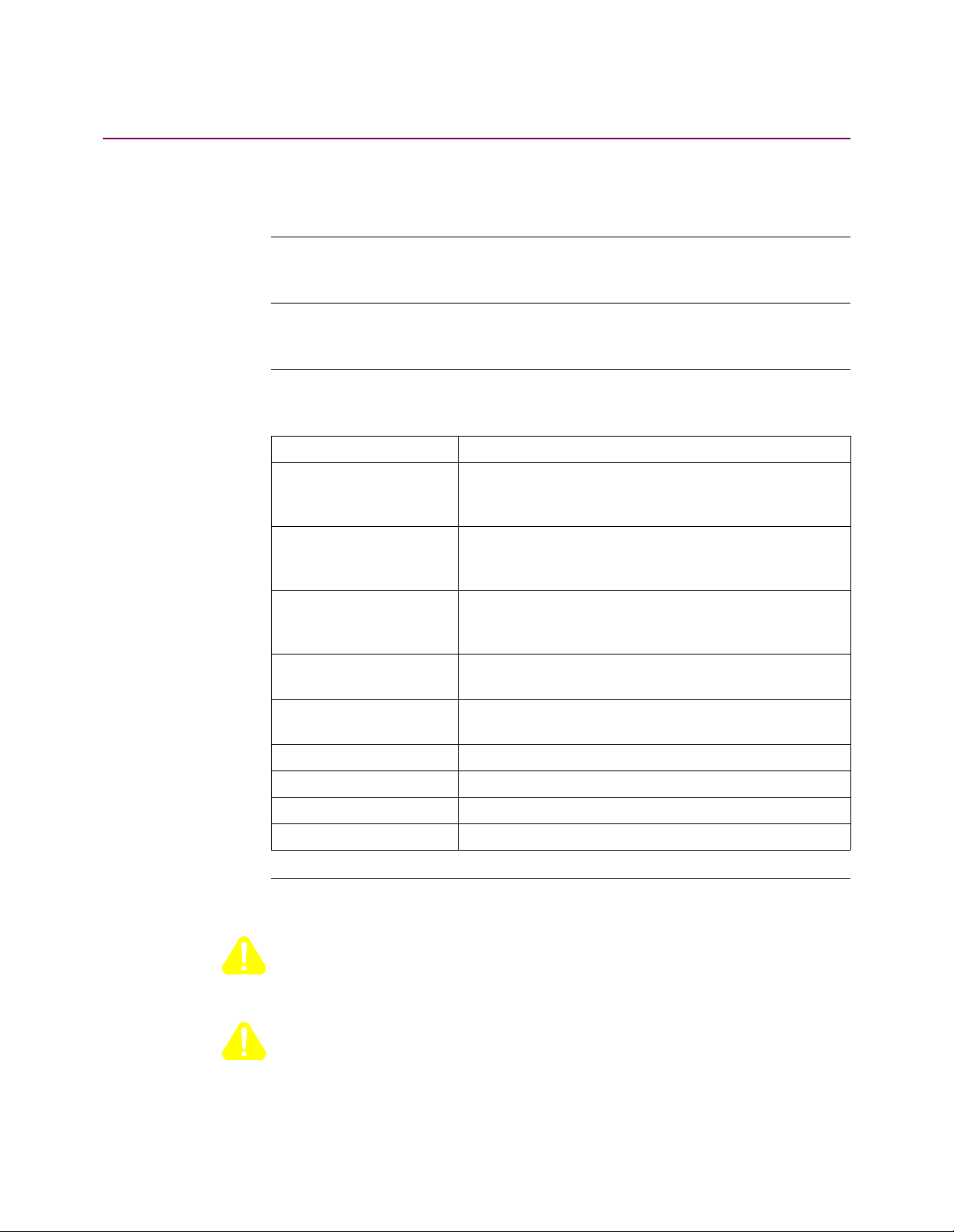
The following table describes the contents of this manual.
This Chapter... Describes:
Chapter 1 PathBuilder S24x, 26x and 27x switch hardware and
software features, and FCC and Telephone Company
procedures and requirements.
Chapter 2 Setting up a PathBuilder S24x, 26x and 27x switch,
including site preparation, how to unpack the unit, and
installation procedures.
Chapter 3 Installing the hardware on the PathBuilder S24x, 26x
and 27x switch, powerup and verification, and installation of software options.
Chapter 4 Maintaining the PathBuilder S24x, 26x and 27x switch
including replacement of cards and motherboa rd.
Chapter 5 Channelized Data option for the PathBuilder S24x, 26x
and 27x switch.
Appendix A Cable pinouts for Ethernet.
Appendix B Product specifications.
Appendix C Error Codes
Appendix D Technical Support
Special Notices The following notices emphasize certain information in the manual. Each serves a
special purpose and is displayed in the format shown:
Caution
Caution provides you with information that, if not followed, can result in damage to
software, hardware, or data.
Mise en Garde
Une mise en garde vous fournit des informations qui, si elles ne sont pas observées,
peuvent se traduire par des dommages pour le logiciel, le matériel ou les données.
vii
Page 8
About This Manual (continued)
Vorsicht
Ein Vorsichtshinweis macht Sie darauf aufmerksam, daß Nichtbefolgung zu
Software-, Hardware- oder Datenschäden führen kann.
Warning
Warning is the most serious notice, indicating that you can be physically hurt.
Avertissement
Un avertissement constitue le message le plus sérieux, indiquant que vous pouvez
subir des blessures corporelles.
Warnung
Eine Warnung ist der ernsthafteste Hinweis auf Körperverletzungsgefahr.
Trademarks PathBuilder is a trademark of 3Com Corporation.
viii
Page 9

Overview
Chapter 1
About the PathBuilder S24x, 26x, and 27x switch
What is the
PathBuilder S24x,
26x, and 27x
switch?
The PathBuilder S24x, 26x, and 27x switch is a multi-protocol LAN/WAN
PathBuilder S200 series switch featuring a high-speed processor and coprocessor
coupled with 12 Mbytes of on-board memory (standard). Designed to address the
needs of large branch offices with higher throughput needs and regional
concentration sites, the PathBuilder S24x, 26x, and 27x switch is available in rackmount configurations.
The PathBuilder S24x, 26x, and 27x switch’s high performance capabilities are
uniquely matched to branch applications with high traffic requirements.
As a regional concentr ator , the PathBuild er S24x, 26x, a nd 27x switch accepts t raffi c
from many branch loc ation s into a single site and tran sfers t he traf fic to ot her devi ces
at the regional or central site.
The PathBuilder S24x, 26x, and 27x switch supports both Frame Relay and X.25.
About the PathBuilder S24x, 26x, and 27x switch 1-1
Page 10
Meshed Cluster
Application
Support
A unique feature of the PathBuilder S24x, 26x, and 27x switch is its ability to
support full meshed cluster applications. This functionality provides host site
resiliency, port count extension, and multiple LAN connectivity.
Examples of how the featu res of th e PathBuild er S24x, 26x, a nd 27x swi tch f uncti on
in specific applications can be found the “Applications” section on page 1-3.
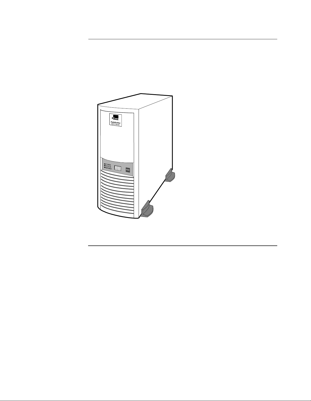
Figure 1-1 shows a PathBuilder S24x, 26x, and 27x switch.
®
Figure 1-1. PathBuilder S24x, 26x, and 27x Switch
1-2 About the PathBuilder S24x, 26x, and 27x switch
Page 11
Applications
Applications
Introduction This section br iefly describe s severa l appl icatio n examples for th e PathBuil der S24x,
26x, and 27x switch.
Performance
Branch Nodes
Because of its high performance capabilities, the PathBuilder S24x, 26x, and 27x
switch can be employed in a variety of branch node applications. For example, the
PathBuilder S24x, 26x, and 27x switch can support a mix of voice and data types,
traditional legacy (SDLC, X.25, Bisync, Async, etc.), and LAN. Because of its high
throughput, the PathBuilder S24x, 26x, and 27x switch can be used in situations
where large file transfers, fast response time, and high numbers of users are the
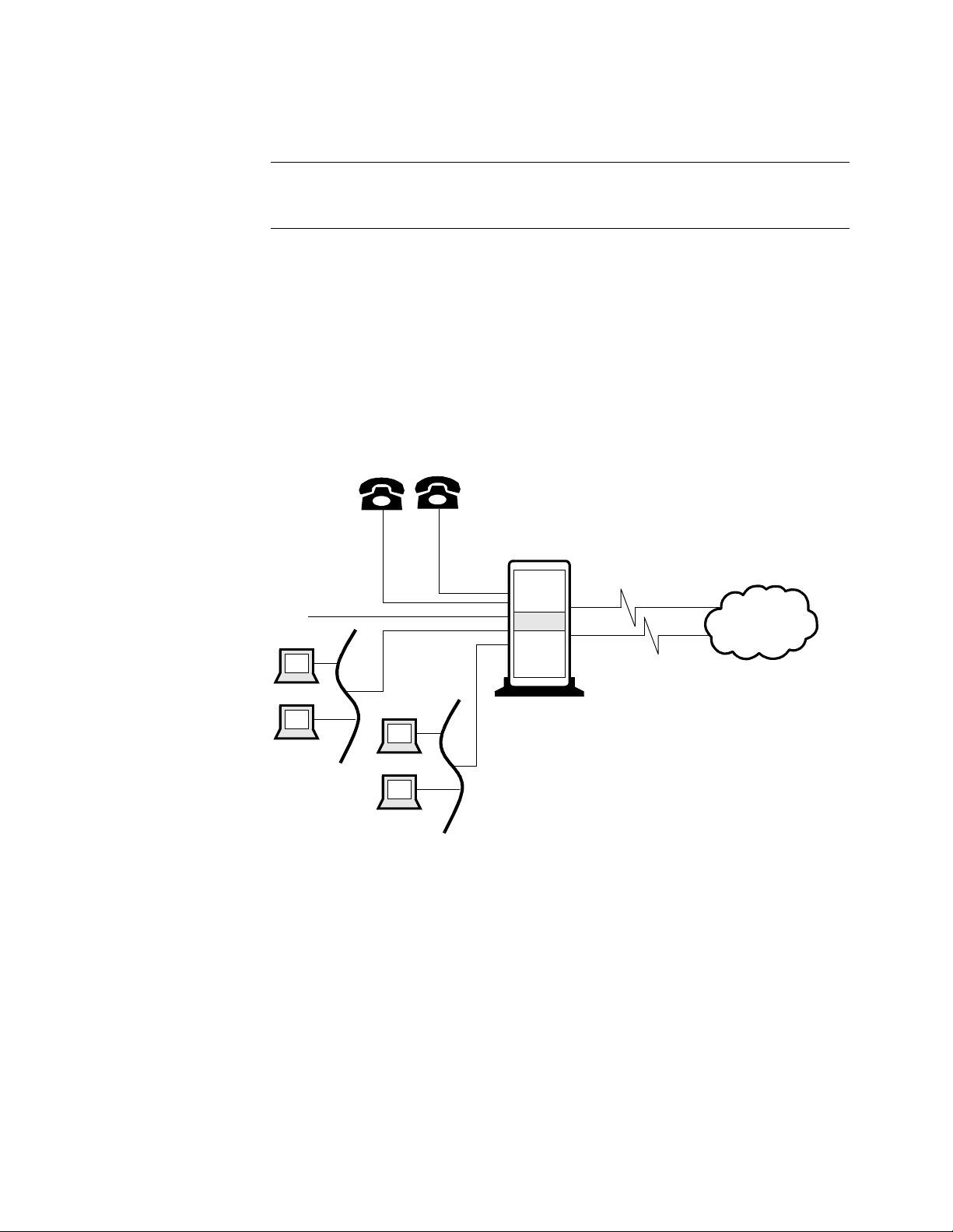
norm. Figure 1-2 is an example of a typical branch node application.
Furthermore, the PathBuilder S24x, 26x, and 27x switch is designed to meet the
needs of an expanding network. With its large RAM capacity and high-speed
processor, the PathBuilder S24x, 26x, and 27x switch can easily adapt to a growing
network with little or no additional hardware.
SNA
PB S200
Public
or Private
Network
Figure 1-2. Performance Branch Node Example
About the PathBuilder S24x, 26x, and 27x switch 1-3
Page 12
Applications
Regional
Concentrator
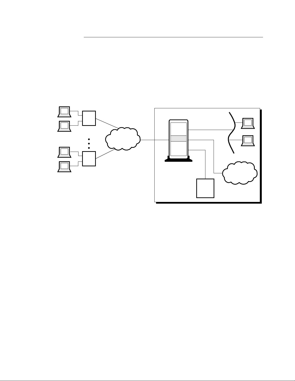
In Figure 1-3, the public network (Frame Relay/X.25) is performing the branch
concentration function with the PathBuilder S24x, 26x, and 27x switch routing the
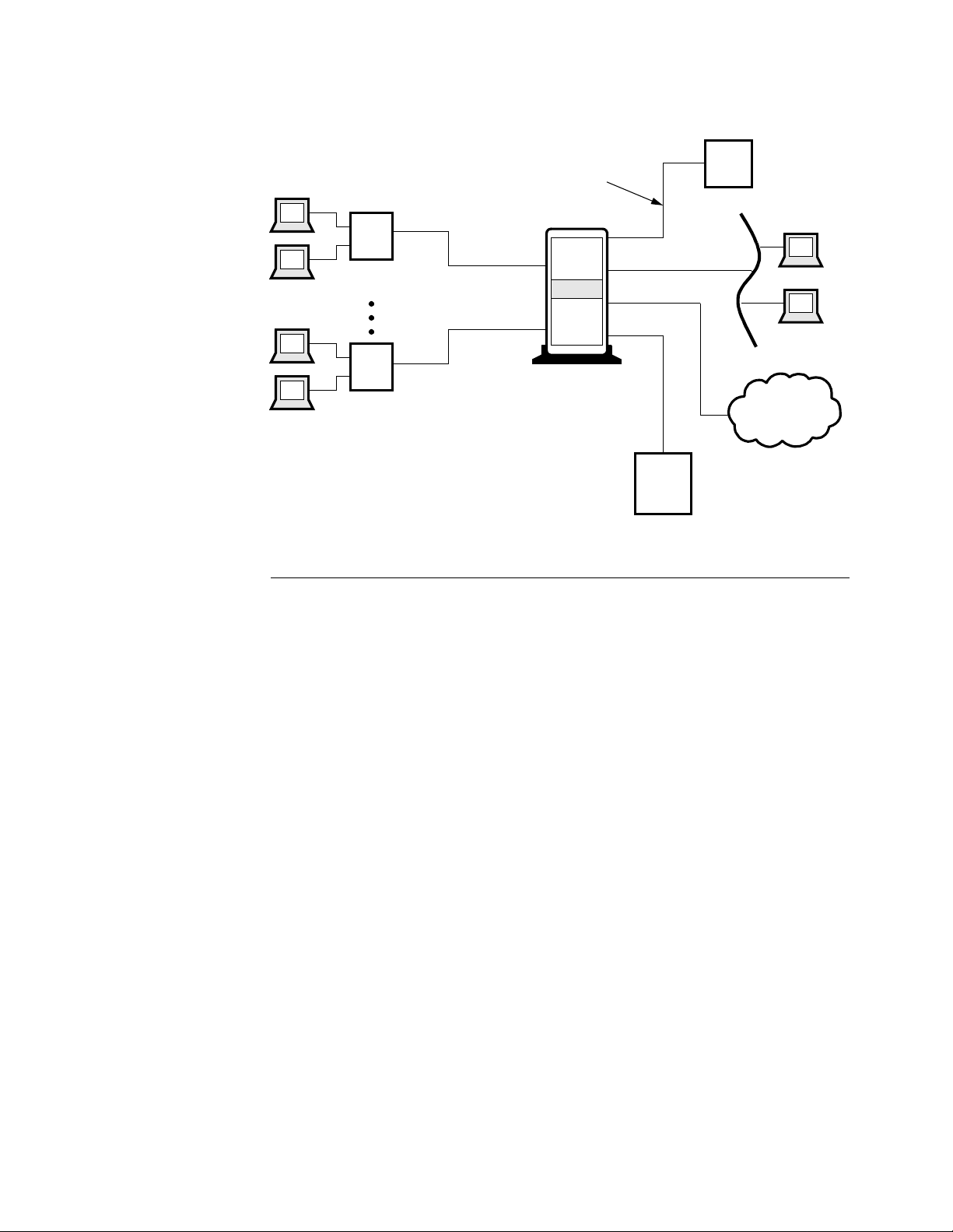
traffic to the appropriate end point. In Figure 1-4, the PathBuilder S24x, 26x, and
27x switch acts as the regio nal conc ent rator s, rece iving t raf fi c from do zens and even
thousands of remote sites, and concentrating the traffic before forwarding it to the
correct location. In this case, the PathBuilder S24x, 26x, and 27x switch is the
regional site.
In both examples, the PathBuil der S24x, 26x, and 27x swi tch could be eith er a single
node or a group of nodes net worked togethe r as a cluste r . The PathBui lder S24x, 26x,
and 27x switch’s cluster feature is described below.
Central Site
Branch 1
PB S200
Frame Relay
or X.25
Branch XX
PB S200
PB S200
(Single Node or Cluster)
PBX
Host
Figure 1-3. Regional Concentrator With Public Network Example
1-4 About the PathBuilder S24x, 26x, and 27x switch
Page 13
High-Speed Link
Applications
Central Site
Branch 1
PB S200
Branch XX
PB S200
PB S200
(Single Node or Cluster)
PBX
Host
Figure 1-4. Regional Concentrator Example
Cluster Application An important new feature available with the PathBuilder S24x, 26x, and 27x switch
is its use in a cluster. This allows as many as four PathBuilder S24x, 26x, and 27x
switches to act a s ing le unit for the pu rpo ses of c onne ct ivi t y. Though configured and
managed as individu al nodes, when t he Pat hBuilder S24x, 26x, and 27x swi tches are
clustered toget her , devi ces at tached t o access po rts on one n ode can h ave calls routed
out the network port of one of the other nodes.
The three high-speed ports on the PathBuilder S24x, 26x, and 27x switch
motherboard provide networking channels between the nodes to pass traffic from
network ports to access ports. The PathBuilder S24x, 26x, and 27x switch cluster
allows for high port count and throughput primarily in support of the regional
concentrator applications.
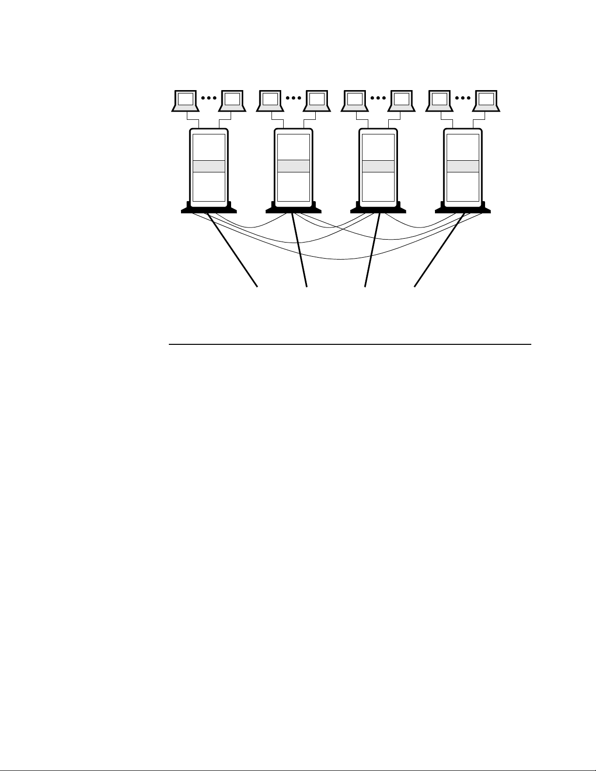
The example in Figure 1-5 is a full mesh cluster which means that any access link
can reach any host connection. If a PathBuilder S24x, 26x, and 27x switch node
within the cluster fails, only those links and host connections directly connected to
that node go down. Placement of host equipment, and use of redundant host
equipment can minimize the impact of any individual node failure. Furthermore,
Link Back Up features in the remotes can limit the degree of remote isolation if part
of the PathBuilder S24x, 26x, and 27x switch cluster fails.
About the PathBuilder S24x, 26x, and 27x switch 1-5
Page 14
Applications
16 Access Ports
PB S200
16 Access Ports 16 Access Ports 16 Access Ports
PB S200
High-Speed Network Links to other Sites
or Backbone LAN Connectors
PB S200
PB S200
Figure 1-5. PathBuilder S24x, 26x, and 27x Switch Cluster Example
1-6 About the PathBuilder S24x, 26x, and 27x switch
Page 15

Features and Protocols
Features and Protocols
Description For a complete listing of the features and protocols supported by your PathBuilder
S24x, 26x, and 27x switch, refer to the Software Release Notice that came with the
operating software.
About the PathBuilder S24x, 26x, and 27x switch 1-7
Page 16
Hardware Components
Hardware Components
PathBuilder S24x,
26x, and 27x
Switch Hardware
Configuration
SSN
Label
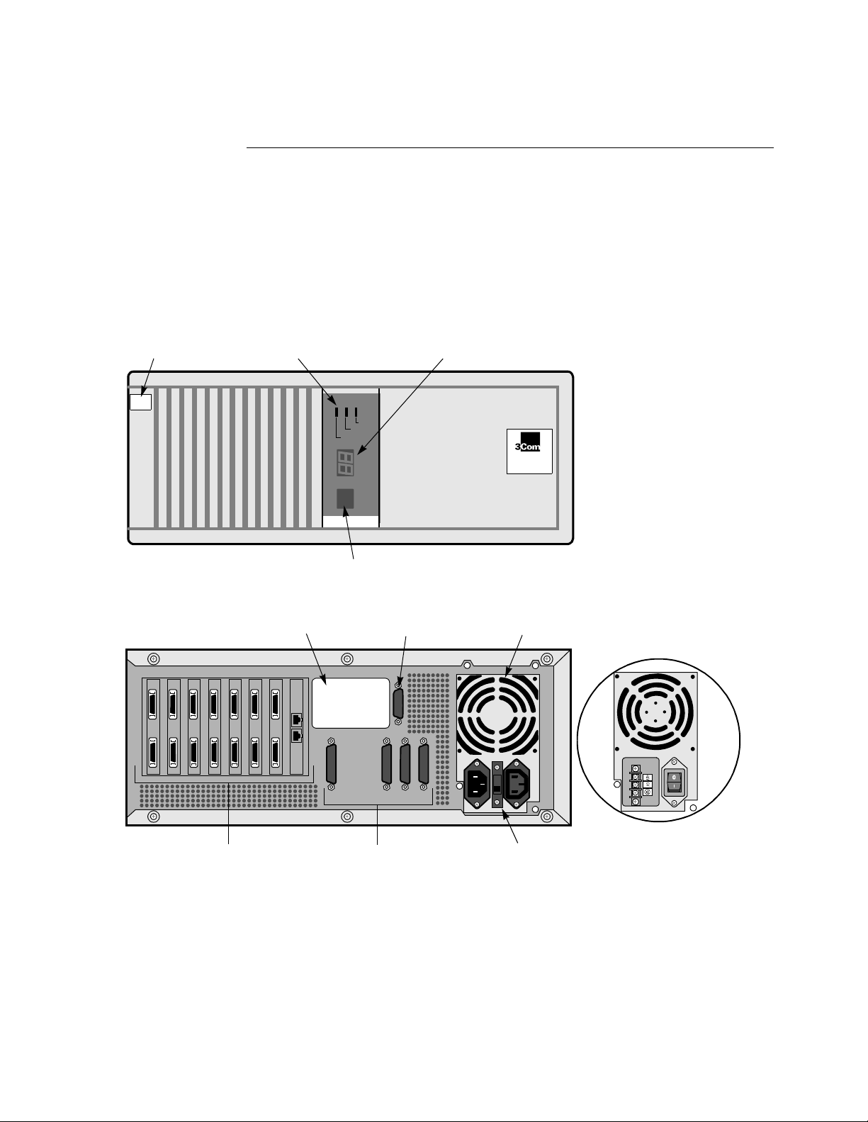
Front View
The PathBuilder S24x, 26x, and 27x switch comes in a rack-mountable
configuration.
The switch contains a motherboard/CPU board, a built-in power supply, and an ISA
bus for up to eight additional interface cards. The PathBuilder S24x, 26x, and 27x
switch has three available serial ports, an Ethernet port, and a CTP port, FLASH
memory, and battery-powere d conf iguration backup. It is eas ily expanded by adding
option cards to the industry standard ISA bus.
Figure 1-6 shows a rack-mountable PathBuilder S24x, 26x, and 27x switch.
Status
LEDs
POWER
STATUS
SERVICE
RESET
Reset
Button
Numeric
LED
PathBuilder
S200 Series
®
Rear View
Expansion
Card Ports
Slots 1 through 8
Figure 1-6. PathBuilder S24x, 26x, and 27x Switch
Product ID
Label
AUI Port 4
(Ethernet Routing)
Serial/Network
I/O Ports 1, 2, 3, 6
Power
Supply
Product
ID Label
115/230 VAC
Voltage
Select
Switch
Optional -48V
Power Supply
1-8 About the PathBuilder S24x, 26x, and 27x switch
Page 17

Hardware Components
Hardware
Components
This table lists and briefly describes the hardware components that make up the
PathBuilder S24x, 26x, and 27x switch. More detailed descriptions of these
components follow.
Component Description
Enclosure A rack-mount unit that contains all the PathBuilder S24x,
26x, and 27x switch processor cards.
Back Panel Contains power outlets, power switch, communication ports,
and slots for I/O cards.
Motherboard Contains five data ports:
• Ports 1 and 2 are DIM ports
• Port 3 is a high-speed/V.36 DTE port
• Port 4 is the Ethernet AUI port
(see below for limitations)
• Port 6 is reserved for the control terminal port
Contains eight full-size expansion slots.
Integral DSU DIM
(Optional)
An option used in installations requiring connection to a
DDS interface conforming to AT&T 62310 or
ANSI T1E1.4/91-006, and running at 56 kbps.
10Base2
Transceiver for AUI
ports (optional)
Lets you accommodate different network configurations
through th e user-selectable Signal Quality Error (SQE)
function.
T1 Dual Port
Digital PBX
Interface Card
PathBuilder S24x,
The T1 dual port digital PBX interface card supports digital
voice communication s, pro viding integrated net w or k a cce ss.
The T1 digital interfaces are used for both voice and data
traffic.
26x, and 27x
E1 Dual Port
Digital PBX
Interface Card
The E1 dual port digital PBX interface card supports digital
voice communications, providing integrated network access
(see Figure 1- 12) .
The E1 interface card is used to support both voice and data
traffic.
DSPM/SM The DSPM/SM card, used at nodes with digital PBX
interfaces, compresses four digital voice channels. It has no
external I/O capabilities.
DSPM with FXS
Analog Inte rface
The analog DSPM/FXS card allows the PathBuilder S24x
switch to support up to t wo voice/fax c hannels per c ard. Each
DSPM/FXS card occupies one ISA slot in the PathBuilder
S24x switch.
DSPM with FXO
Analog Inte rface
The analog FXO daughtercard (when mounted on the
DSPM/HC) allows the PathBuilder S244 and S254 swi tch to
support one voice/fax channel per card. Each DSPM/HX
with FXO daughtercard combination occupies one ISA slot
in the PathBuilder S244 and S254 switch.
About the PathBuilder S24x, 26x, and 27x switch 1-9
Page 18

Hardware Components
Component Description (continued)
Ethernet Port 4
Limitations
DSPM with E&M
Interface
The PathBuilder S26x switch Analog DSPM/E&M card
allows the PathBuilder S26x switch to support up to two (2)
voice/fax channels per card. Each E&M card occupies one
ISA slot in the PathBuilder S26x switch. The Path Builder
S26x switch E&M card supports both two- and four-wire
interfaces.
Consider these limitations when using the Ethernet Port 4:
• The port does not support Bridging (refer to the Bridging Option,
Part No. T0008-16). When configuring this port, you are not prompted
for the bridge link number.
• The port does not support SLAC.
• When configuring the Ethe rnet Port 4, you are not prompted for the connector
type. Ethernet Port 4 only supports AUI.
1-10 About the PathBuilder S24x, 26x, and 27x switch
Page 19

Hardware Components
Enclosure
Introduction This section provides detailed information about the parts of the PathBuilder S24x,
26x, and 27x switch enclosure.
Front Panel The PathBuilder S24x, 26x, and 27x switch front panel (see Figure 1-6) has:
• Three status LEDs
• A 2-character numeric LED display
• A RESET switch
Status LEDs The three status LEDs are:
• Power (green) — When on, indi cates that p ower is on an d all DC vol tages ar e
within specifications.
• Status (green) — When on, indicates that t he Pat hBui lde r S24x, 26x, and 27x
switch node is executin g either a p ower-up d iagnostic o r a software downl oad.
This LED is normally off.
• Service (yellow) — When on, indicates a hardware failure. This LED is
normally off.
Numeric LED
Display
Reset Switch The RESET switch resets the node. Pre ssing the RESET swit ch is the equi valent of a
Power Supply The power supply is mounte d at the top rear of the chassis. The AC switchable powe r
The 2-character numeric LED display provides system diagnostic codes. When the
Service LED is on, a 2-digit code on the numeric LED display corresponds to a
certain event.
power-up operation which clears all existing calls and brings down all links.
supply can operate at a nominal 110 or a nominal 230 Volts. For information about
maintaining and replacing the power supply, refer to Chapter 4, Maintenance.
Note
For this unit, the -48VDC Power Option is also available.
About the PathBuilder S24x, 26x, and 27x switch 1-11
Page 20
Hardware Components
Motherboard
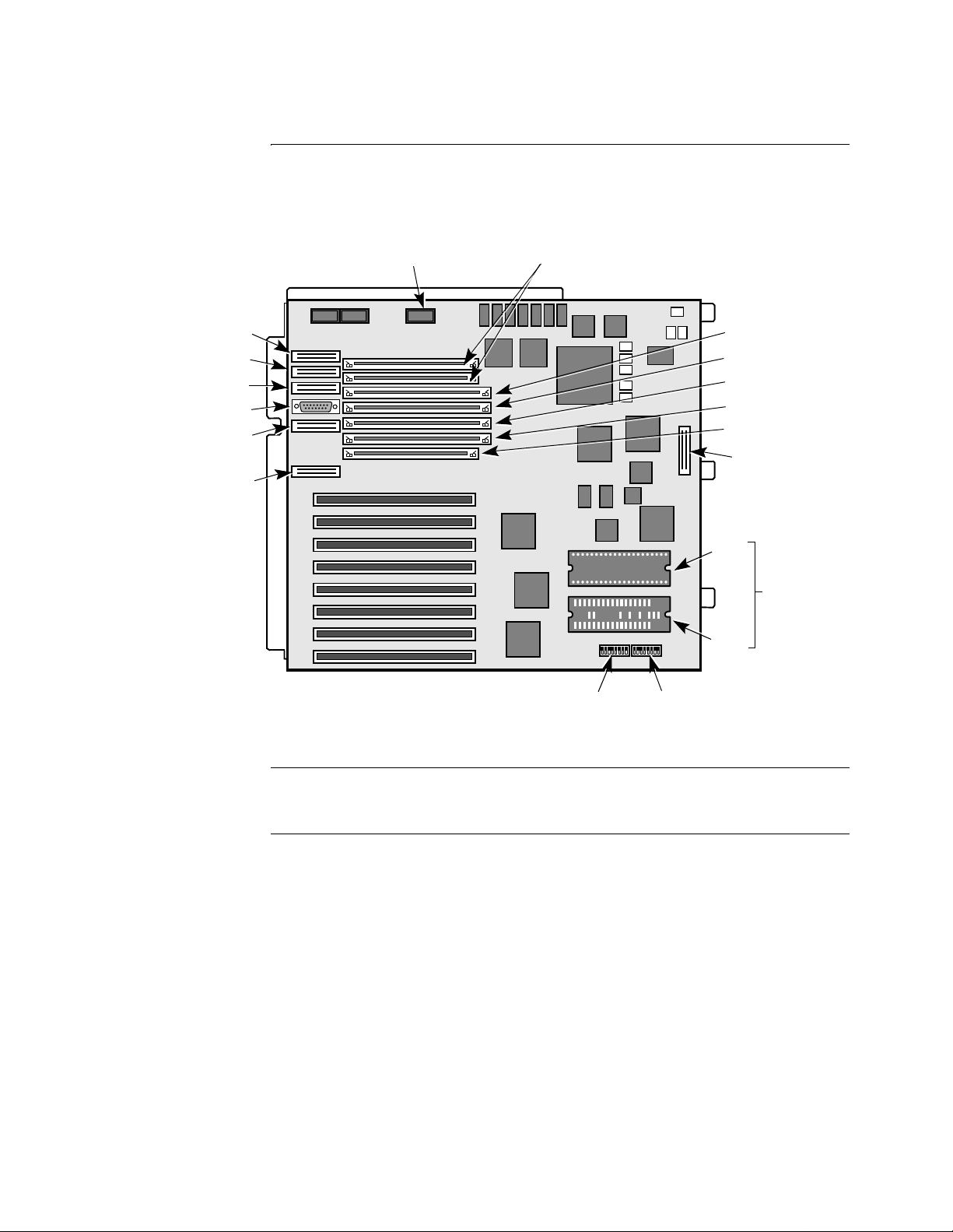
Parts of the
Motherboard
Etherspan
Port 1
Port 2
Port 3
AUI
Port 4
Port 6
This section describes some of the components that make up the PathBuilder S24x,
26x, and 27x switch motherboard. In addition, this section describes some of the
daughtercards that can be found on the motherboard, shown in Figure 1-7.
Power Supply
Ringer Status
DRAM SIMM
Slots 1 and 2
1
2
3
4
5
6
7
8
Flash SIMM Slot
Optional Flash
SIMM Slot
CMEM SIMM Slot
Data Compression
SIMM Slot
Global DRAM
SIMM Slot
LED Connector
Port 1
DIMs
Port 2
Switch 2
Switch 1
Figure 1-7. Motherboard
RAM The PathBuilder S24x, 26x, and 27x swit ch comes standard with 16 Mbytes of loc al
DRAM for image execution and 8 Mbytes of global memory for buffer storage.
Ports There are four serial data port DB-25 connectors for network or access functions
(2.048 Mbps):
• Ports 1 and 2 (DB 25) are Data Interface Module (DIM) ports
• Port 3 (DB 25) is a V.36 DTE port
• Port 4 (DB 15) is an Ethernet AUI port
• Port 6 (DB25 ) is the Control Terminal Port (EIA232)
1-12 About the PathBuilder S24x, 26x, and 27x switch
Page 21
Hardware Components
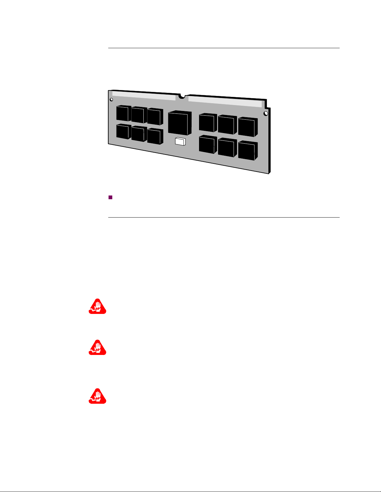
FLASH SIMM The FLASH Single In-line Memory Module (SIMM) holds a compressed image of
the operating software. This module is electrically erasable and reprogrammable.
An optional FLASH SIMM can be i ns tal l ed f or bac kup. T hese modules are instal le d
in one of the SIMM slots (1 or 2). Figure 1-8 shows the SIMM.
Figure 1-8. FLASH SIMM
Note
The chips on your SIMM may vary from the one shown inFigure 1-8.
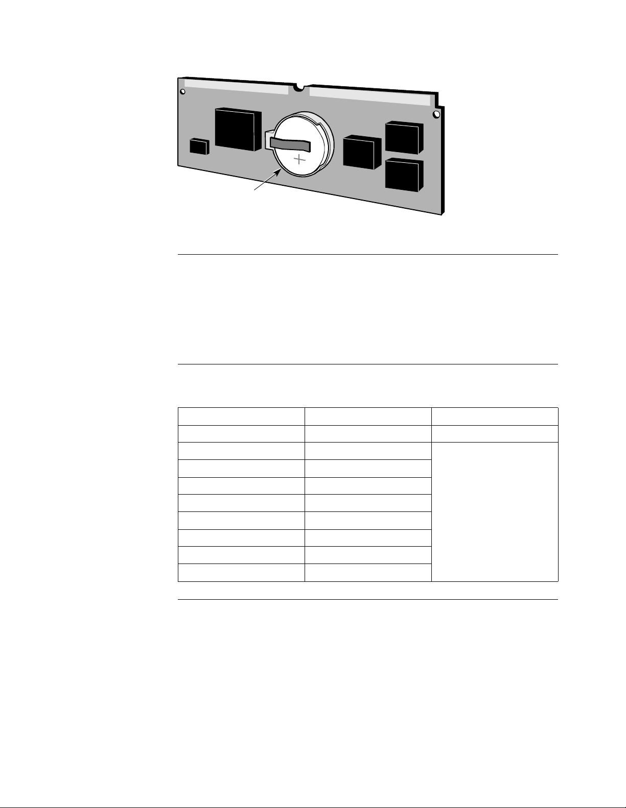
CMEM SIMM The Configuration Memory Module ( CMEM) SIMM has 512 Kbytes o f memory and
provides the real time clock function. The CMEM is backed up by a lithium battery
in case of a power disruption.
Each PathBuilder S24x, 26x, and 27x switch has a Software Serial Number (SSN)
burned into a PROM located on the CMEM card. This SSN is used to verify the
software options that are enabled for that node. It is on the CMEM SIMM card for
easy removal and replacement in case of a motherboard failure.
The CMEM is installed in the SIMM slo t (see Figure 1-7 for slot lo cation).
Figure 1-9 shows the CMEM.
Warning
Only qualified service personnel should perform the procedure described in this
section. If the battery is installed incorrectly, it could explode after the PathBuilder
S200 series switch product is powered up, damaging the unit.
Avertissement
Seules des personnes qualifiées peuvent mettre en pratique les procédures décrites
dans cette section. Si la batterie n’est pas correctement installée, elle risque
d’exploser après la mise en marche du produit PathBuilder S200 series switch et
d’endommager l’unité.
Warnung
Die in diesem Abschnitt aufgeführten Vorgänge sollten ausschließlich von
qualifiziertem Servicepersonal durchgeführt werden. Wenn die Batterie
unsachgemäß installiert wird, kann sie nach dem Einschalten des PathBuilder S200
series switch-Produkts explodieren
About the PathBuilder S24x, 26x, and 27x switch 1-13
Page 22
Hardware Components
Lithium Battery
Figure 1-9. CMEM SIMM
Expansion Port
I/O Slots
Slot Number and
Port Numbers
The PathBuilder S24x, 26x, and 27x switch motherboard has eight full-size
expansion card slots (see Figure 1-6). Expansion I/O cards have I/O connectors that
extend through the rear panel.
Port numbers for the ports o n the I/O cards h ave a fixed relationship to th e chassis
expansion slot number. Six port numbers are reserved for each slot. If a slot contains
an I/O card that does not support the full port count reserved for that slot, or the slot
is empty, the extra port numbers remain unused.
This table shows the port numbers associated with each card type.
Slot Number Port Number Associated Card
Motherboard I/O 1-6 Motherboard
1 7-12 Voice cards (E & M, FXS,
2 13-18
3 19-24
Server Module, T1, E1).
The T1/E1 is restricted to
Slot 8.
4 25-30
5 31-36
6 37-42
7 43-48
8 49-54
Description of
Serial/Network
Ports
Ports 1 through 3 are con nect ed to t he mothe rboard with ri bbon cab les. Por ts 1 an d 2
are DIM ports and are functional only if a DIM is present. Port 3 is a dedicated V.36
DTE port.
Ports 1, 2, 3, and 6 on the r ear panel of the chassis are DB-25 femal e connect ors. Port
4, (the Ethernet AUI port) uses a DB-15 connector. Ports 1 and 2 may require
adapters, depending on the DIM used. An adapter cable is available for Port 3.
1-14 About the PathBuilder S24x, 26x, and 27x switch
Page 23

Hardware Components
How Ports Are
Used
DIMs without a
Cable Adapter
DIMs with a Cable
Adapter
The following table describes how the ports are used.
Port Number Use
1, 2, and 3 Recommended for network port connection or cluster
connectivity. Ports 1 and 2 have variable interfaces, depending
on the DIMs.
4 Ethernet AUI port for routing applications.
6 Control Terminal Port (CTP). When operating as an
asynchronous interface, it can support data rates up to 115.2
kbps. Default CTP configuration parameters are 9600 baud,
8-bit characters, 1 stop bit, no parity. This is an EIA 232-D
DCE port using a DB-25 connector.
Ports 1 and 2 support a DSU DIM without the use of cable adapters.
If cable adapters are used, Ports 1 and 2 can support the following DIMs:
• High Speed (V.36)
• V.35
• V.11/ISO-4903
Each DIM port can be configured independently of the other port. For example, you
can install: two V.35 DIMs; one V.35 DIM and one V.11 DIM; or two V.11 DIMs.
The cable adapter pinouts are described in Appendix A, Cables.
About the PathBuilder S24x, 26x, and 27x switch 1-15
Page 24
Hardware Components
Back Panel
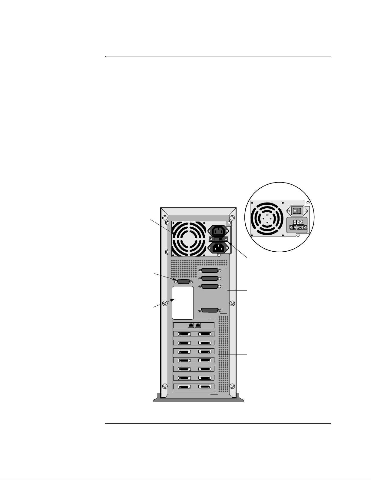
Back Panel
Components
The components of the back panel are:
• Serial/Network I/O Ports. Ports 1, 2, 3, and 6 are DB-25 connectors. Port 4
is a DB 15 connector.
• AC Power Supply. The rear of the Power Supply has two (male and female)
power source connector s (one i s fo r connec tion to an AC sour ce and the othe r
is an AC outlet) along with a selectable 115 VAC or 230 VAC switch. For
most international usage, the switch must be set for 230 VAC.
• DC Power Supply. The uni t can be shi ppe d with the -4 8VDC Power Opti on.
The terminal block of the -48VDC has 5 screws. The two outermost screws
are for attachment. The negative wire terminal is second from the left; the
positive wire terminal is in the middle; the ground is second from the right.
• Expansion Card Ports. The expansion card ports differ depending on what
card is installed in that slot.
Figure 1-10 shows the PathBuilder S24x, 26x, and 27x switch back panel.
Optional -48V
Power Supply
Power
Supply
115/230 VAC
Voltage Select
AUI Port 4
(Ethernet Routing)
Product
ID Label
Switch
Serial/Network
I/O Ports 1,2, 3, 6
Expansion
Card Ports
Slots 1 through 8
Figure 1-10. PathBuilder S24x, 26x, and 27x Switch Back Panel
1-16 About the PathBuilder S24x, 26x, and 27x switch
Page 25
Hardware Components
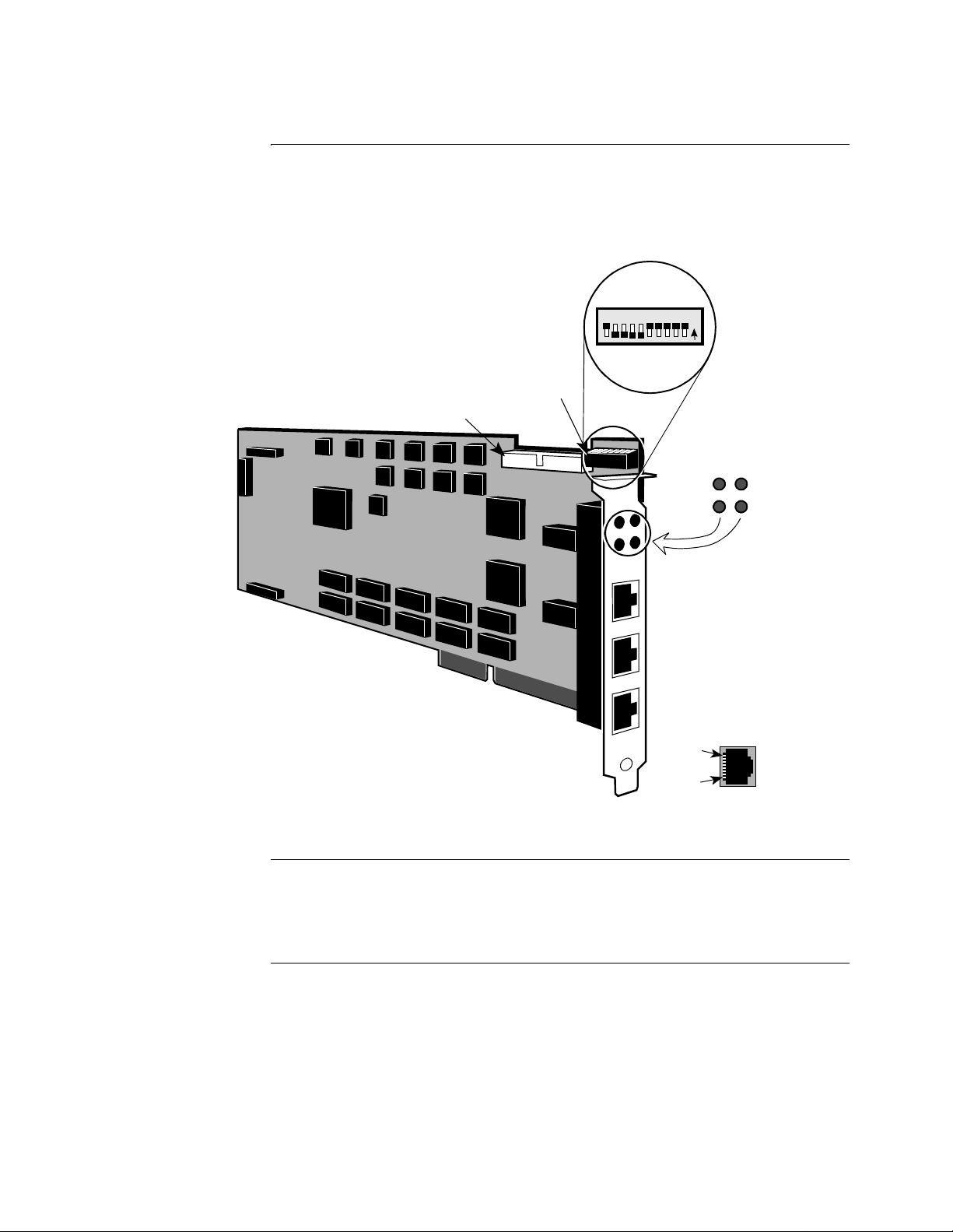
TI Dual Port Digital PBX Interface Card
Introduction The T1 dual port digital PBX interface card supports digital voice communications,
providing integrated network access. The T1 interface card is installed primarily in
North America and Japan. A 2-megabyte T1 card is required for passing data and
voice traffic.
SW1 DIP Switch Bank
MVIP Bus Interface Conn ector
ISA Bus Interface
87654321109
N
O
Port 49 LED
Run LED
Port 49 Interface
Port 50 Interface
Serial Diagnostic Port (Not Supporte d)
Pin 8
Port 50 LED
SysFail LED
Pin 1
Figure 1-11. T1 Dual Port Digital PBX Interface Card
Description Each T1 dual port digit al PBX i nt erf ace card uses an Indust ry Standard Architec ture
(ISA) bus interface and a Multi-Vendor Integration Protocol (MVIP) bus interface.
The MVIP bus interface provides multiplexed digital access within the PathBuilder
S24x, 26x, and 27x switch chassis.
Function T1 dual port digital PBX interface ca r ds provide the digital interfaces for
connections to a PBX. The T1 dual port di gital PBX interfac e cards bring PCM voice
and channel signaling into the node. The PCM voice data and voice signaling is
routed to a DSPM/SM card over the MVIP bus for compression and transmission to
the remote end.
About the PathBuilder S24x, 26x, and 27x switch 1-17
Page 26

Hardware Components
Slot Restriction The T1 dual port digital PBX interface card occ upie s s lot 8 i n the Pat hBui lde r S2 4x,
26x, and 27x switch chassis.
DIP Switch
Location
DIP Switch
Settings
T1/CSU Daughter
Card
The T1 dual port digital PBX in terface card contains a single DIP switch bank (SW1)
used to assign the card’s I/O base address.
Set the DIP switches on the T1 dual port digital PBX interface card as shown in
Figure 1-11.
The T1/CSU Daughtercard provides a 1.544 MHz point-to-point interface for North
American service that conforms to AT&T 62411/62421 standard. The card is FCC
Part 68 Registered and uses eternal clocking derived from the telephone network.
One or two T1/CSU Daughter Car ds can be ins talled onto t he T1 Dual Por t card. T he
top card supports port 49 and the bottom supports port 50.
For instructions for installing the T1/CSU card, refer to “Installing th e T1/CSU
Daughter Card” section in Chapter 3.
Required Cables These cables ship with the T1 dual port digital PBX inter face card and ar e required to
cable the T1 dual port digital PBX interface card to the DSPM/SM cards in the node.
Cable Description Function
One 4-position 40-pin
MVIP ribbon cable
Connects up to 3 DSPM/SM cards to interconnect
digital voice traffic between individual cards in the
same PathBuilder S24x, 26x, and 27x switch node.
One 8-position 40-pin
MVIP ribbon cable
Connects 4 or more DSPM/SM car ds to in terconnec t
digital voice traffic between individual cards in the
same PathBuilder S24x, 26x, and 27x switch node.
Two 8-pin modular to
DB15 cables
3-ft adapter converter cables used to convert the
8-pin modular connector on the front of the T1/E1
card to a DB15 connector (Product Code 17269).
1-18 About the PathBuilder S24x, 26x, and 27x switch
Page 27

Hardware Components
LED Status
Indicators
The T1 dual port digital PBX interface card contains four LEDs that can be viewed
through the rear bracket.
LED Color LED is... ...Indicating
Port 49
Yellow
Port 50
Yellow
RUN
Green
SYSFAIL
Yellow
OFF
ON
OFF
ON
OFF
ON
OFF
ON
Normal operation
Carrier failure on Port 49span
Normal operation
Carrier failure on Port 50 span
Card failure
Card Active
Normal operation
Card failure
About the PathBuilder S24x, 26x, and 27x switch 1-19
Page 28

Hardware Components
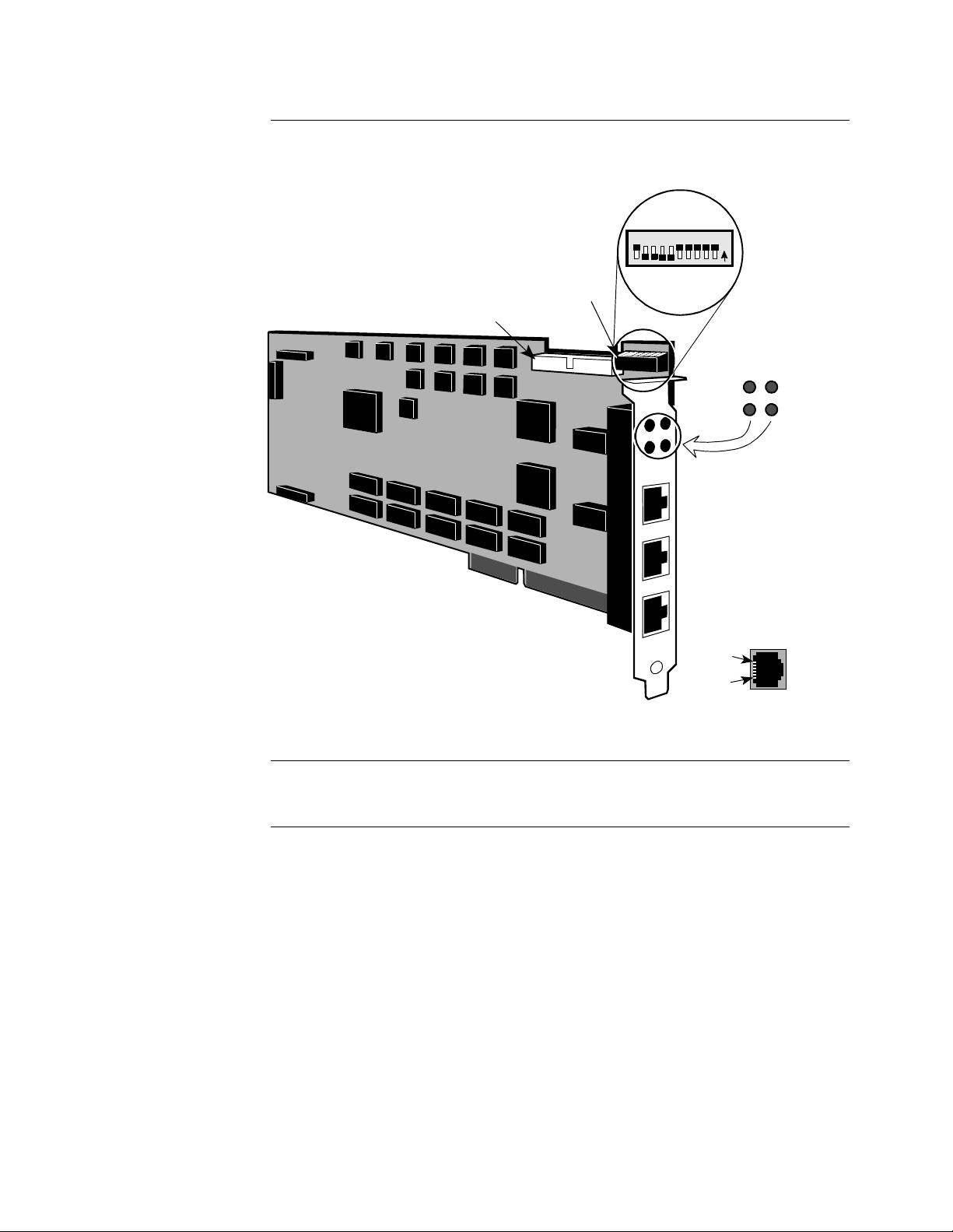
E1 Dual Port Digital PBX Interface Card
Introduction The E1 dual port digital PBX interface card supports digital voice communications,
providing integrated network access (see Figure 1-12). The E1 interface card is
installed primarily in Europe and South America. A 2-megabyte E1 card is required
for passing data traf f ic and voice tra ffic.
Description Each E1 dual port digit al PBX i nt erf ace card uses an Indust ry Standard Architec ture
(ISA) bus interface and a Multi-Vendor Integration Protocol (MVIP) bus interface.
The MVIP bus inter face pro vides a multipl exed digit al acce ss within the Pa thBuilder
S24x, 26x, and 27x switch chassis.
The E1 dual port digital PBX interface card has two E1 ports (CAS signaling only),
handles E1 lines with or without CRC4, and supports 120Ω and 75Ω (with the
addition of an optional cable). The interface type is 8-pin modular.
Function E1 dual port digital PBX interface ca r ds provide the digital interfaces for
connections to a PBX. The dual port digital PBX interface cards bring PCM voice
and channel signaling into the node. The PCM voice data and voice signaling is
routed to a DSPM/SM card over the MVIP bus for compression and transmission to
the motherboard.
Slot Restriction The E1 dual port digital PBX interface card can only occ upy slot 8 in the PathBui lder
S24x, 26x, and 27x switch chassis.
1-20 About the PathBuilder S24x, 26x, and 27x switch
Page 29
Hardware Components
E1 Dual Port Digital
PBX Interface Card
Illustration
Figure 1-12 shows an example of the E1 dual port digital PBX interface card.
87654321109
SW1 DIP Switch Bank
MVIP Bus Interface Conn ector
N
O
Port 49
Alarm LED
Run LED
Port 49 Interface
Port 50 Interface
Port 50
Alarm LED
SysFail LED
DIP Switch
Location
DIP Switch
Settings
ISA Bus Interface
Serial Diagnostic Port
Pin 6
Pin 1
Figure 1-12. E1 Digital PBX Interface Card
The E1 dual port digital PBX in terface card contains a single DIP switch bank (SW1)
used to assign the card’s I/O base address.
Set the switches as shown in Figure 1-12.
About the PathBuilder S24x, 26x, and 27x switch 1-21
Page 30

Hardware Components
Required cables The following cables, includi ng two pi gt ai l cables, ship with the E1 dual port digi t al
PBX interface card and are required to cable the E1 card to the DSPM/SM cards in
the PathBuilder S24x, 26x, and 27x switch node.
Cable Description Function
One 4-position 40-pin
MVIP ribbon cable
Connects up to three DSPM/SM cards to
interconnect digital voice traffic between individual
cards in the same PathBuilder S24x, 26x, and 27x
switch node.
LED Status
Indicators
One 8-position, 40-pin
MVIP ribbon cable
Connects four or more DSPM/SM cards to
interconnect digital voice traffic between individual
cards in the same PathBuilder S24x, 26x, and 27x
switch node.
T wo 8-pin modular to DB15
For 120Ω connection.
cables
T w o 8-p in modul ar to BNC
For 75Ω connection.
cables
The E1 dual port digital PBX interface card contains four LEDs that can be viewed
through the rear bracket:
LED Color LED is... ...Indicating
Port 49 Ye llow OFF
ON
Port 50 Ye llow OFF
ON
RUN Green OFF
ON
SYSFAIL Yellow OFF
ON
Normal operation
Carrier failure on Port 49 span
Normal operation
Carrier failure on Port 50 span
Card failure
Microprocessor Activity
Normal operation
Card failure
1-22 About the PathBuilder S24x, 26x, and 27x switch
Page 31

Hardware Components
Not
DSPM/SM Card
Introduction The Digital Signal Processing Module/Server Module (DSPM/SM) supports T1 or
E1 dual port digital PBX interface ca r ds.
Description The DSPM/SM card, used at nodes with digital PBX interfaces, compresses four
digital voice channels. It has no external I/O capabilities.
Function PCM voice and voice signaling, brought into the PathBuilder S24x, 26x, and 27x
switch node by the T1/E1 ca rds, is rout ed to a DSPM/SM ca rd over the MVIP b us for
compression and transmission to the remote end.
When You Receive
the Card
When you receive a DSPM/SM card, do the following:.
Step Action
1 Remove the card from the packing material.
2 Inventory the contents of the shipping container.
e
No cables are shipped with the DSPM/SM card. The appropriate
Multi-Vendor Integration Protocol 40-pin ribbon cable and othe r cables
ship with t he T1 or E1 dual port digita l interface cards.
3 Power off the PathBuilder S24x, 26x, and 27x switch node.
4 Install the card into the PathBuilder S24x, 26x, and 27x switch node.
5 Cable the card to the T1 or E1 dual port digital interface cards as
required.
About the PathBuilder S24x, 26x, and 27x switch 1-23
Page 32

Hardware Components
DSPM/ SM Card
Illustration
Figure 1-13 shows an example of the DSPM/SM card.
MVIP Bus Interface Connector
Installed
MVIP Clock Termination Jumpers
Not
Installed
Figure 1-13. DSPM/SM Card
Jumper Locations Figure 1-13 shows the location of jumpers on the DSPM/SM card that terminate the
Multi-Vendor Integration Protocol clock.
Installing Jumpers Figure 1-13 shows how to insta ll t he jumpers on the DSPM/ SM ca rd to te rminat e the
Multi-Vendor Integration Protocol clock.
The DSPM/SM card with the jumpers set to the installed position must be located
furthest from the T1 or E1 card as shown in Figure 1-14 (the T1/E1 card is always
located in slot 8). All other DSPM/SM cards must have their jumpers in the “not
installed” position.
1-24 About the PathBuilder S24x, 26x, and 27x switch
Page 33

Hardware Components
Cables Required No cables ship with the DSPM/SM card; however, the DSPM/SM card must be
cabled to the T1 or E1 dual port digital interface using a Multi-Vendor Integration
Protocol 40-pin ribbon cable, as Figure 1-14 shows.
To support 12 voice channels, for instance, you need three DSPM/Server Module
cards.
Note: The DSPM/SM card with
the jumpers set to the installed
position must be located furthest
away from the E1 or T1 card, the
top card, as shown in this figure. ®
MVIP 4-Position Cable
DSPM/SM
T1 or E1
Restricted to Slot 8
Figure 1-14. Cabling T1/E1 Card to DSPM/SM Cards
About the PathBuilder S24x, 26x, and 27x switch 1-25
Page 34

Hardware Components
Not
DSPM Card with Analog E&M Interface
Introduction The DSPM/E&M card supports two analog E&M interface voice channels.
Description The Analog DSPM/E&M card allows the PathBuilder S24x, 26x, and 27x switch to
support up to two (2) voice /fax channel s per card. Each E&M card o ccupie s one I SA
slot in the PathBuilder S24x, 26x, and 27x switch. The PathBuilder S24x, 26x, and
27x switch E&M card supports both two- and four-wire interfaces.
Function The DSPM/E&M card allows a PBX to attach to one of its two connectors.
-48V Ringer/ Power
Supply Card
Required
Cables Required The DSPM/E&M interface card requires a -48V ringer/power supply cable to
When You Receive
the Card
The DSPM/E&M card requires installation of a -48V ringer/power supply card and
enclosure into the PathBuilder S24x, 26x, and 27x switch node to support interface
types II, III, and V.
Interface type I does not require a -48V ringer/power supply.
support interface types II, III, and V.
The -48V ringer/power supply cable connects up to six DSPM cards to the power
supply. The cable ships with the -48V ringer/power supply.
For details on how to cabl e t he DSPM card to the -48V ringer/ powe r s uppl y, refer to
the “-48V Ringer/Power Supply Card and Enclosure” section on page 1-53.
When you receive a DSPM/E&M card, do the following:
Step Action
1 Remove it from the packing material.
2 Inventory the contents of the shipping container.
e
No cables ar e shipped with the DSPM/E&M ca rd. The appropriate
6-position power cabl e and stat us cable ship with the -48V ring er/power
supply card that must be used in conjunction with the DSPM/E&M
card.
3 Set jumpers as required.
4 Power off the node.
5 Install the card into the PathBuilder S24x, 26x, and 27x switch node.
6 Cable the card to the -48V ringer/power supply as required.
1-26 About the PathBuilder S24x, 26x, and 27x switch
Page 35

Hardware Components
DSPM/E&M Card
Illustration
Figure 1-15 shows an example of the DSPM card with an analog E&M interface.
MVIP Clock Termination Jumpers (Not Used)
2-or 4-wire Jum pe rs
Complex Impedance Jumpers
-48V Power Supply Connector
Port 1
Port 2
Port 1 RM
(Remote Busy)
Port 2 RM
(Remote Busy)
Figure 1-15. DSPM/E&M Card
Port 1 LC
(Local Busy)
Pin 8
Pin 1
Port 2 LC
(Local Busy)
About the PathBuilder S24x, 26x, and 27x switch 1-27
Page 36

Hardware Components
LEDs The card contains four LEDs that can be viewed through the rear bracket.
LED Color LED is... ...Indicating
Port 1 Local
Busy
Green On
Off
local physical connection is active
(offhook)
local physical connection is idle
(onhook)
Port 1 Remote
Busy
Port 2 Local
Busy
Port 2 Remote
Busy
Green On
Off
Green On
Off
Green On
Off
remote end is active (offhook)
remote end is idle (onhook)
local physical connection is active
(offhook)
local physical connection is idle
(onhook)
remote end is active (offhook)
remote end is idle (onhook)
1-28 About the PathBuilder S24x, 26x, and 27x switch
Page 37

Hardware Components
Setting Jumpers for DSPM Card with Analog E&M Interface
Introduction The DSPM/EM card has a total of 12 jumpers that you can set for various
applications if required:
• Ten jumpers for two- or four-wire operation
• Two jumpers for MVIP clock termination (not used at present)
Default Jumper
Settings
Jumper Definitions Jumpers J11 through J15 are associated with Port 1.
The DSPM/EM card ships from the factory with the ten jumpers for two- or
four-wire operation set to four-wire.
Jumper
4-Wire/600 2-Wire/600 2-Wire/UK
Number
J11 600 600 COM COM
J124W2W2W2W
J13 Don’t Care
(Default
Germany)
J14 600 600 COM COM
J15 4W (removed) 2W (installed) 2W (installed) 2W
Jumpers J21 through J25 are associated with Port 2.
Jumper
4-Wire/600 2-Wire/600 2-Wire/UK
Don’t Care
(Default
Germany)
Number
J21 600 600 COM COM
2-Wire/
Complex
Germany
Complex
UK Germany
(installed)
2-Wire/
Complex
Germany
Complex
J224W2W2W2W
J23 Don’t Care
(Default
Germany)
J24 600 600 COM COM
J25 4W (removed) 2W (installed) 2W (installed) 2W
About the PathBuilder S24x, 26x, and 27x switch 1-29
Don’t Care
(Default
Germany)
UK Germany
(installed)
Page 38

Hardware Components
Complex
Impedance for UK
and Germany
Setting jumpers for two-wire UK complex and two-wire Germany complex
impedance as noted in the “Jumper Definitions” section above, matches the
impedance required in each country, respectively. Refer to Figure 1-15 and
Figure 1-17.
370
620 .31µƒ
Figure 1-16. UK Complex Impedance
220
820
.115µƒ
Figure 1-17. Germany Complex Impedance
1-30 About the PathBuilder S24x, 26x, and 27x switch
Page 39

Jumper Locations Set the jumpers to the positions as shown in Figure 1-18.
J15
4W
J13
2W
J21
2W
4W
2W
J25
J22
C 6
J23
4W
2W
UG U G
J15
(Port 1)
J11
J12
C 6
Hardware Components
J144WJ24
C 6
C 6
2W
Complex
Germany
(Port 1)
2W
UK Complex
(Port 2)
2W 4W
2W
Complex
Germany
J14
(Port 1)
J24
(Port 2)
COM 600Ω COM 600Ω
(Port 2)
2W
UK Complex
J11
(Port 1)
J12
(Port 1)
COM 600Ω
2W
(Port 2)
2W 4W
J25
(Port 2)
2W 4W
J13
J21
J22
COM 600Ω
J23
Figure 1-18. Jumper Locations for DSPM E&M Card
Installing Jumpers Figure 1-19 illustrates how to install two- or four-wire jumpers into proper position.
Installing 3 Position Jumpers
Jumpers
Installing 2 Position Jumpers
4-Wire (removed)
Jumpers
2-Wire
(installed)
Figure 1-19. Installing Jumpers
About the PathBuilder S24x, 26x, and 27x switch 1-31
Page 40

Hardware Components
Not
DSPM Card with FXS Analog Interface
Introduction The Analog DSPM/FXS (Foreign Exchange Station) card supports two analog FXS
interfaces.
Description The analog DSPM/FXS card allows the PathBuilder S24x, 26x, and 27x switch to
support up to two voice/fax channels per card. Each DSPM/FXS card occupies one
ISA slot in the PathBuilder S24x, 26x, and 27x switch.
Function The FXS interface provides a ringing voltage which alerts a station of an incoming
call’ s -48V to power the phone/fa x, and its -48V loo p current det ector to detec t when
the station goes off hook. As a result, an analog DSPM card with an FXS interface
allows a telephone set, fax machine, or telephone key set to attach to one of its two
connectors.
When You Receive
the Card
When you receive a DSPM/FXS card, do the following:.
Step Action
1 Remove the card from the packing material.
2 Inventory the contents of the shipping container.
e
No cables are shipped with the DSPM/FXS card. The appropriate
6-position power cabl e and stat us cable ship with the -48V ring er/power
supply card that must be used in conjunction with the DSPM/FXS card.
3 Power off the PathBuilder S24x, 26x, and 27x switch node.
4 Install the card into the PathBuilder S24x, 26x, and 27x switch node.
5 Cable the card to the -48V ringer/power supply as required.
-48V Ringer/Power
Supply Required
Cables Required The DSPM/FXS interface card requires a -4 8V ringer/power supply cable, whi ch can
The DSPM/FXS card requires installation of a -48V ringer/power supply card and
enclosure into the PathBuilder S24x, 26x, and 27x switch node. Refer to the
“-48V Ringer/Power Supply Card and Enclosure” section on page 1-38.
attach up to two DSPM/FXS cards to the power supply. The cable ships with
the -48V ringer/power supply card and enclosure.
For details concerning how to install and cable the DSPM card to the -48V ringer/
power supply card and enclosure, refer to the “-48V Ringer/Power Supply Card and
Enclosure” section on page 1-38.
1-32 About the PathBuilder S24x, 26x, and 27x switch
Page 41

Hardware Components
DSPM/FXS Card
Illustration
Figure 1-20 shows an example of the DSPM card with an analog FXS interface.
MVIP Clock Termination
Jumpers (Not Used)
-48V Power Supply
Connector
Port 1
Port 2
Port 1 RM
(Remote Busy)
Port 2 RM
(Remote Busy)
Port 1 LC
(Local Busy)
Port 2 LC
(Local Busy)
Figure 1-20. DSPM Card with Analog FXS Interface
Pin 6
Pin 1
About the PathBuilder S24x, 26x, and 27x switch 1-33
Page 42

Hardware Components
LEDs The card contains four LEDs that can be viewed through the rear bracket.
LED Color LED is... ...Indicating
Port 1 Local
Busy
Green On
Off
local physical connection is active
(offhook)
local physical connection is idle
(onhook)
Port 1 Remote
Busy
Port 2 Local
Busy
Green On
Off
Green On
Off
remote end is active (offhook)
remote end is idle (onhook)
local physical connection is active
(offhook)
local physical connection is idle
(onhook)
Port 2 Remote
Busy
Green On
Off
remote end is active (offhook)
remote end is idle (onhook)
Jumper Locations The DSPM/FX S interface card has no jumpers that must be set.
For Australian
Users
Only 3Com approved engineering staff can install and program this card.
The QDU rating for the voice compression algorithm used by this equipment is:
* 8k 4.5 QDU
* 16k 2.63 QDU
The total number of QDU in any application must be managed according to the
guidelines in the Private Network Design Guide published by Standards Australia.
Failure to adhere to these guidelines is a breach of Australian Communications
Authority regulations.
1-34 About the PathBuilder S24x, 26x, and 27x switch
Page 43

Hardware Components
Not
DSPM Host Card with FXO Analog Interface
Introduction The Analog DSPM/HC (host card) supports one analog FXO (Foreign Exchange
Office) interface. The FXO is a daughtercard that is mounted onto the DSPM/HC.
Description The analog FXO daughtercard (when mounted on the DSPM/HC) allows the
PathBuilder S24x, 26x, and 27x switch to support one voice/fax channel per card.
Each DSPM/HX with FXO daughtercard combination occupies one ISA slot in the
PathBuilder S24x, 26x, and 27x switch.
Function The FXO interface provides a method for connecting to the PBX, simulating a
phone. The FXO interface:
• has a ring voltage detector for detecting an incoming call
• can generate a loop closure for acknowledging an incoming call request
• can generate a call request to a PBX
When You Receive
the Card
When you receive a DSPM/HC with FXO daughtercard, do the following:.
Step Action
1 Remove the card from the packing material.
2 Inventory the contents of the shipping container.
e
No cables are shipped with the DSPM/HC with FXO interface.
3 Power off the PathBuilder S24x, 26x, and 27x switch node.
4 Install the card into the PathBuilder S24x, 26x, and 27x switch node.
About the PathBuilder S24x, 26x, and 27x switch 1-35
Page 44

Hardware Components
DSPM/HC with FXO
Card Illustra ti o n
Figure 1-21 shows an example of the DSPM/HC with an analog FXO daughtercard.
FXO Daughtercard
Port 1
(Remote Busy)
Port 1
(Local Busy)
Port 2
(Remote Busy)
Port 2
(Local Busy)
Pin 6
Pin 1
Figure 1-21. DSPM/HC Card with Analog FXO Daughtercard
LEDs The card contains four LEDs that can be viewed through the rear bracket.
LED Color LED is... ...Indicating
Port 1 Local
Busy
Port 1 Remote
Busy
Port 2 Local
Busy
Port 2 Remote
Busy
Green On
Off
Green On
Off
Green On
Off
Green On
Off
local physical connection is active (offhook)
local physical connection is idle (onhook)
remote end is active (offhook)
remote end is idle (onhook)
local physical connection is active (offhook)
local physical connection is idle (onhook)
remote end is active (offhook)
remote end is idle (onhook)
1-36 About the PathBuilder S24x, 26x, and 27x switch
Page 45

Hardware Components
Jumper Locations The DSPM/HC with FXO daughtercard has no jumpers that must be set.
About the PathBuilder S24x, 26x, and 27x switch 1-37
Page 46

Hardware Components
-48V Ringer/Power Supply Card and Enclosure
Introduction One -48V ringer/power supply card and enclosure is required per PathBuilder S24x,
26x, and 27x switch node for
• Analog DSPM/FXS cards
• DSPM/E&M cards using interface signaling types II, III, and V.
DSPM/E&M card with an interface signaling of type I does not require a -48V
ringer/power supply card and enclosure.
Description The -48V ringer/power supp ly card comes in a n enclos ure, which you must ins tall i n
the PathBuilder S24x, 26x, and 27x switch if you are field upgrading to support the
Voice option.
New PathBuilder S24x, 26x, and 27x switch nodes ordered with the voice option
ship with the -48V ringer/power supply factory installed.
The -48V ringer/power supply card supports the following:
• 12 E&M ports, or 6 DSPM/E&M cards
• 4 FXS ports, or 2 DSPM/FXS cards
Function The -48V ringer/power supply card rings up to four phones at a time.
-48V Ring/Power
Supply Types
Jumper Definitions The -48V ringer/ power s upply c ard ha s two se ts of jumpers for v arious requi reme nts.
Jumper Locations The jumpers for 25 or 50 Hz ring frequency are located on the -48V ringer/power
Installing Jumpers Figure 1-22 and Figure 1-23 show jumper positions on the -48V r inger/p ower suppl y
There are two versions of the -48V ringer/power supply: Standard and Enhanced.
• The Standard -48V ringer/power supply (see Figure 1-22) can support two
FXS cards.
• The Enhanced -48V ringer/power supply (see Figure 1-23) can support six
FXS cards. (Available in the Fall of 1998.)
• One set of jumpers to enable or disable the -48V ringer supply output (should
not be changed from its default setting of enabled.)
• One set of jumpers to control the frequency of the ring supplied to the DSPM/
FXS card: 25 Hz (US) or 50 Hz (Europe).
For more information see Figure 1-22 and Figure 1-23.
supply card as shown in Figure 1-22 and Figure 1-23.
card for 25 or 50 Hz ring frequency and how to install the jumpers for 25 or 50 Hz
ring frequency.
1-38 About the PathBuilder S24x, 26x, and 27x switch
Page 47

Hardware Components
Cables Required The -48V ringer/power supply card is shipped with one cable with six connectors.
-48V Power
Supply Connector
(to each DSPM card)
Ring Enable Jumper
Must be Configured
as Shown
Jumper Set
for 25 Hz
Ring Frequency
Power Connectors to
Jumper Set
for 50 Hz
Ring Frequency
Main AC Power Supply
Status Connector
Figure 1-22. Standard -48V RInger/Power Supply Card and Enclosure
About the PathBuilder S24x, 26x, and 27x switch 1-39
Page 48

Hardware Components
Ring Enable Jumper
Must be Configured
as Shown
J11 Jumper Set for 25 Hz
Ring Frequency
J11 Jumper Set for 25 Hz
Ring Frequency
J12
J11
Jumper Locations
Output Connectors
Power Connectors to
Main AC Power Supply
Status Connector
Figure 1-23. Enhanced -48V RInger/Power Supply Card and Enclosure
1-40 About the PathBuilder S24x, 26x, and 27x switch
Page 49

Hardware Components
10BaseT Transceiver
Description This transceive r is desig ned to pr ovide Ethern et 10base T suppor t fo r the Pa thBuil der
S24x, 26x, and 27x switch. It can accommodate different 10BaseT configurations
through the user-selectable Signal Quality Error (SQE) function. See Figure 1-24.
Some network devices do not recognize this signal. If the attached network device
does not recognize this SQE signal, set the switch to Off.
RJ45 Connector
SQUE Switch
15-Pin D-Type Connector
Figure 1-24. 10BaseT Transceiver
The 10BaseTransceiver can be connected to the Ethernet LAN (ELAN) card or the
PathBuilder S24x, 26x, and 27x switch’s Port 4.
About the PathBuilder S24x, 26x, and 27x switch 1-41
Page 50

Radio Frequency Interference Regulations
Radio Frequency Interference Regulations
Introduction This section explains the radio frequency interference regulations.
FCC This equipment has been tested and found to comply with the limits for a Class A
digital device, pursuant to Part 15 of the FCC rules, CISPR Publication 22:85 and
EN 55022:87. These limits are designed to provide reasonable protection against
interference when the equipment is operated in a commercial environment. This
equipment generates, uses, and can radiate radio frequency energy, and, if not
installed and us ed in a ccorda nce with t he ins tru ctio n manual, may c aus e inte rfer ence
to radio communications.
Changes or modifications not expressly approved by 3Com could void the user’s
authority to operate the equipment.
Canadian DOC This digital apparatus does not exceed the Class A limits for radio noise emissions
from digital apparatus set out in the radio interference regulations of the Canadian
Department of Communications.
Operation of this equipment in a residential area is likely to cause interference, in
which case the user will be required to take adequate measures to correct the
interference at his/her own expense.
General This product was verified under test conditions that include some use of shielded
DTE cable(s). Use o f dif ferent cables will invalid ate verif ication and in crease the risk
of causing interference to radio and TV reception.
You can obtain the proper cables from 3Com.
1-42 About the PathBuilder S24x, 26x, and 27x switch
Page 51

Telecommunications Regulations
In the United States, FCC rules Part 68 require that the followi ng user instru ctions
are provided:
The telephone company has the right to ask you for registration information about
your equipment that is connected to the telephone line. When requested, you
should provide your equipment’s FCC registration number and ringer equivalence
number (REN), if applicable.
The user instructions shall include the FCC registration number and a detailed list
of all ports that connect to the network. The information provided must also
include USOC connector jacks, the facility interface codes (FOC), service order
codes, (SOCs), and REN, as applicable.
REN is used to determine t he number of devices t hat can be connected to an anal og
telephone line, but is generally not applicable to digital service equipment.
Excessive RENs on the line may result in t he devices’ not ri nging in respo nse to an
incoming call. Contact the telephone company to determine the maximum REN
sum for the calling area; in general, it should not exceed five.
The telephone company may change its equipment, operations, or procedures.
If these changes affect your equipment or service, the telephone company will
provide written notice so you may make the necessary changes with uninterrupted
service.
FCC regulations and telephone company procedures prohibit connection of
customer-pro vided equipment to t elephone company-p rovided coin servi ce (central
office-implemented systems). Connection to party lines is subject to state tariffs.
Contact your telephone company if you have any questions about your telephone
line.
Telecommunications Regulations
About the PathBuilder S24x, 26x, and 27x switch 1-43
Page 52

Telecommunications Regulations
In Canada, the following equipment attachment limitations and information must be
provided in the user instructions:
The Canadian Department of Communicati ons label identifie s certi fied equipment .
This certification means that the equipment meets certain telecommunications
network protective operational and safety requirements. The Department does not
guarantee the equipme nt will opera te to the user’s satisfaction.
Before installing this equipment, users should ensure that it is permissible to be
connected to the facilities of the local telecommunications company.
The equipment must also be i nstalled u sing a n accepta ble method of connect ion. In
some cases, the company’s inside wiring associated with a single line individual
service may be extended by means of a certified connector assembly (telephone
extension cord). The customer should be aware that compliance with the above
conditions may not prevent degradation of service in some situations.
Repairs to certified equipment should be made by an authorized Canadian
maintenance facil ity de signa ted by the suppl ier. Any repairs or alterati ons made by
the user to this equipment, or equipment malfunctions, may give the
telecommunications company cause to request the user to disconnect the
equipment.
Users should ensure for th eir own pro tec tion th at the el ectr ical gr ound co nnecti ons
of the power utility, telephone lines, and internal metallic water pipe system, if
present, are connected together. This precaution may be particularly important in
rural areas.
Caution
Users should not atte mpt to make such c onnection thems elves, but sh ould contact t he
appropriate electric inspection authority, or electrician, as appropriate.
Mise en Garde
Les utilisateurs ne doivent pas établir de telles connexions eux-mêmes. Ils doivent
contacter une personne compétente ou un électricien.
Warnung
Benutzer sollten nicht versuchen, diese Verbindung selbst herzustellen, sondern
dazu die zuständige Aufsichtsbehörde für Elektroinstallationen bzw. einen
Elektroin stallateur kontaktieren.
Note
The Load Number (LN) assigned to each terminal device denotes the total load
percentage to be connected to a telephone loop used by the device to prevent
overloading. The loop termination can consist of any combination of devices as
long as their total LNs do not exceed 100.
1-44 About the PathBuilder S24x, 26x, and 27x switch
Page 53

FCC and Telephone Company Procedures and Requirements
FCC and T elephone Company Procedures and Requirements
Introduction The following tables provide the information that is needed for ordering telephone
company network connections for the 3Com PathBuilder S24x, 26x, and 27x switch
V.22 bis modem.
How to Order Connections in the U.S.A.
Ordering
Connections for
the T1/CSU
Service
Description
PSTN-permissive RJ11C 0.8B 02LS2
Service
Description
PSTN- permissive CA11A 15 LS
To order the proper connections for a PathBuilder S24x, 26x, and 27x switch with a
T1 Dual Port Interface card with T1/CSU daughtercards, provide the telephone
company with the following information:
• Interface type
• Required USOC jack connector number
• Service code
• Facility interface codes
Interface Type USOC Jack
56-kbps di gital interface RJ48 6.0P 04DU9-BN
56-kbps di gital interface RJ48 6.0P 04DU9-1Z N
56-kbps di gital interface RJ48 6.0P 04DU9-1KN
56-kbps di gital interface RJ48 6.0P 04DU9-1S N
USOC Jack
REN Facility Interface
Connector
How to Order Connections in Canada
Connection
LN Network
Arrangement
Connector
Service
Code
Facility Interface
Code
Interface
Code
If Problems Arise If a ny of yo ur tel ephone equipmen t is n ot oper atin g corr ectly, immediately remove it
from the telephone line before it harms your network. If the telephone company
notes the problem, they will notify you in advance, if possible, and may temporarily
disconnect your service. When you are notified, you will be given the chance to
correct the problem and be informed of your right to file a complaint with the FCC.
About the PathBuilder S24x, 26x, and 27x switch 1-45
Page 54

FCC Information
FCC Information
Customer-Provided
Telephone
Equipment
FCC and T elephone
Company
Procedures and
Requirements
FCC regulations and telephone company procedures prohibit connection of
customer-provided equipment to telephone company-provided coin service (central
office-implemented systems). Connection to party lines is subject to state tariffs.
Occasionally, the telephone company may make changes in their equipment,
operations, or procedures. If these changes affect your equipment or service, the
telephone company will provide written notice so you can make the necessary
changes to maintain uninterrupted service.
Contact your telephone company if you have any questions about your telephone
line.
In some circumstances, the telephone company may ask you for information about
your equipment that is connected to the telephone line. Within the United States
(at the request of the telephone company), you should provide your equipment’s
FCC registration number. This number is AT9USA-21085-DD-N and is located on
the unit’s label.
Before you connect the PathBuilder S24x, 26x, and 27x switch DSU option to the
network, you must provide the telephone company with the information shown
below.
Type of Interface USOC Jack
Connector
REN/Service
Code
Facility Interface
Code
56-kbps digital interface RJ48S 6.0F 04DU5-56
1-46 About the PathBuilder S24x, 26x, and 27x switch
Page 55

FCC Information
Regulations
Concerning
Electromagnetic
Radiation
The Federal Communications Commission (FCC) of the United States of America
and the Industry and Science Canada (ISC) have published regulations that govern
the allowable limits of emanation of radio frequency energy of computing devices
and associated peripherals. These regulations are concerned with interference to
radio communications, such as radio and television. The regulations require
equipment for use in the United States or Canada to be labeled and to be
accompanied by the following notice:
This equipment has been tested and found to comply with the limits for a Class A
digital device, pursuant to Part 15 of the FCC Rules. These limits are designed to
provide reasonable protecti on against interfe rence when equ ipment i s operated in a
commercial environment. This equipment generates, uses, and can radiate radio
frequency energy and, if not installed and used in accordance with the instruction
manual, may cause interference to radio communi cat io ns.
This digital apparatus does not exceed the Class A limits for radio noise emissions
from digital apparatus set out in the radio interference regulations of the ISC.
Operation of this equipment in a residential area is likely to cause interference in
which case the user will be required to take adequate measures to correct the
interference.
This product was verified under test conditions that include use of shielded DTE
cable(s). Leased line cab les with 1.5 turns through a ferrit e cylinder were also used.
Use of different cables will invalidate verification and increase the risk of causing
interference to radio and TV reception.
You can obtain the proper cables from 3Com.
Correcting
Interference
Additional
Information
If this equipment causes interference to radio or television reception, which can be
determined by t urning the eq uip ment of f and on, you a re encoura ged to tr y to co rrect
the interference by one or more of the follo wing measures :
• Reorienting the receiving antenna
• Relocating the equipment with respect to the receiver
• Moving the equipment away from the receiver
• Plugging the equipment into a different outlet so that the equipment and
receiver are on different circuits
If necessary, you should consult the dealer or an experienced radio/television
technician for additional circuits.
You may find the following booklet prepared by the FCC helpful: How to
Identify and Resolve Radio-TV Interference Problems. This booklet is available
from the U.S. Government Printing Office, Washington, D.C. 20402,
Stock No. 004-000-00345-4.
About the PathBuilder S24x, 26x, and 27x switch 1-47
Page 56

FCC Information
1-48 About the PathBuilder S24x, 26x, and 27x switch
Page 57

Chapter 2
Preparation and Unpacking
Overview
Introduction This chapter summarizes information you need and activities you must complete
before installing your PathBuilder S24x, 26x, and 27x switch system.
It describes how to select an operating environment and how to unpack the
enclosure.
Preparation and Unpacking 2-1
Page 58

Before Installing Your PathBuilder S24x, 26x, and 27x Switch
Before Installing Your PathBuilder S24x, 26x, and 27x Switch
Introduction Before installing your PathBuilder S24x, 26x, and 27x switch, be sure to complete
the followin g steps:
• Verify that the configuration worksheets are accurate and complete. Be sure
that they are prepared beforehand according to your network requirements.
• Be sure you have all the required information from your service provider.
• Configure, connect, and test the network termination unit (for example, a
CSU) through which the PathBuilder S24x, 26x, and 27x switch connects to
the networ k.
Selecting an
Operating
Environment
Choose a site for your PathBuilder S24x, 26x, and 27x switch that is within 6 feet
(1.8m) of an appropriate power source. Depending on your application and the
country in which the PathBuilder S24x, 26x, and 27x switch will operate, this may
be a grounded 115 or 230 VAC outlet.
Caution
The voltage select switch on the back of the power supply must be set for 230 VAC
for use where applicable.
The area selected should be free of accumulated dust and environmental extremes.
The acceptable temperature range for operating the unit is 32× to 122×F (0× to
50×C) at sea level. Relative humidity should not exceed 90% (noncondensing).
Allow at least 12 inches (30.5 cm) in back of the unit for cable clearance and air
circulation.
Mise en Garde
Le commutateur de sélection de tension à l’arrière du bloc d’alimentation doit être
sur la position 230 VAC (tension courant alternatif) pour une utilisation appropriée.
Choisissez un emplacement propre et sûr, dont la température se situe entre 0 et 50
degrés Celsius (32 et 122 degrés Fahrenheit ) au niveau de la mer. L’humidité ne doit
pas excéder 90% (sans condensation).
Laissez un espace d’au moins 30,5 cm (12 pouces) derrière l’unité pour les câbles et
la circulation de l’air.
Vorsicht
Der Spannungsumschalter auf der Rückseite des Netzteils muß für die
entsprechenden Länder auf 230 VAC eingestellt sein.
Der Betriebsort sollte staubfrei und keinen extremen Umwelteinflüssen ausgesetzt
sein. Der akzeptabl e Temperaturbereich für den Be tr ieb des Geräte s lie gt z wische n 0
und 50 Grad Celci us auf Meer eshöhe. Die r el ativ e Luft fe uchti gkeit soll te 90 % ( nicht
kondensierend) nicht übersteigen.
Halten Sie einen Wandabstand von mindestens 30,5 cm auf der Geräterückseite zur
ungehinderten Verlegung der Kabel und Entlüftung ein.
2-2 Preparation and Unpacking
Page 59

Before Installing Your PathBuilder S24x, 26x, and 27x Switch
Caution
To avoid overheating the unit’s circuitry, you should never place anything on top of
the unit, within one inch (2 .5 cm) of the venti lation s lots on the fron t panel, or wit hin
12 inches (30.5 cm) of the back of the unit.
Mise en Garde
Afin d’éviter tou te surchauf fe des cir cuits de l’u nité, ne place z aucun obje t sur l’unit é
à moins de 2,5 cm (1 pouce) des conduit s de venti lati on du panne au avant et à moins
de 30,5 cm (12 pouces) de l’arrière de l’unité.
Vorsicht
Zur Vermeidung einer Überhitzung der Geräteschaltkreise sollten Sie keine
Gegenstände auf dem Gerät plazieren. Zu den Entlüftungsöffnungen der
Vorderabdeckung sollte ein Abstand von 2,5 cm und zur Rückseite des Gerätes
von 30,5 cm eingehalten werden.
Preparation and Unpacking 2-3
Page 60

Unpacking
Unpacking
Introduction The PathBuilder S24x, 26x, an d 27x swit ch’s printed circuit cards and other internal
components are in st alled in the enc lo sure before the uni t is shipped fr om t he factory.
In addition to the enclosure and its components, you may find within the shipping
carton a sleeve containing the power cord (if appropriate for your installation).
Checking the
Equipment
Thoroughly check the cartons and their contents for damage in shipment.
If damage has occurred, contact the shipping agent.
Next, lift the unit from the shipping carton and remove the foam packing material.
Direct any questions about missing parts to your 3Com representative.
2-4 Preparation and Unpacking
Page 61

The PathBuilder S24x, 26x, and 27x Switch Rackmount Kit
The PathBuilder S24x, 26x, and 27x Switch Rackmount Kit
Introduction You can install the PathBuilder S24x, 26x, and 27x switch in a standard Electronics
Industry Association (EIA) 19-inch equipment rack.
EIA Rackmount Kit The PathBuilder S24x, 26x, and 27x switch EIA Rackmount kit contains the
following components:
• One Mounting Shelf
• Two adjustable Rear Mounting brackets for rear rail attachment
• Four Phillips-head 10-32 x .38 long screws with integral lock washers
• Eight Phillips-head 12-24 x.50 long screws for front and rear rail attachment
• Three longer #6 screws
When Checking the
EIA Rackmount Kit
Be aware of the following issues when checking the components of your rackmount
kit:
• The Mounting Shelf and adjustable Rear Mounting brackets ship fastened
together at the Mounting bracket’s front-most adjustment hole. This prevents
damage during shipping. Disassemble these components prior to installation.
• The four Phillips-head 10-32 x .38 long screws ship in holes securing the
Mounting Shelf to the Rear Mounting brackets. Remove them to separate the
shelf and brackets.
• The eight Phillips-head 12-24 x .50 long screws ship in a small plastic bag.
Preparation and Unpacking 2-5
Page 62

The PathBuilder S24x, 26x, and 27x Switch Rackmount Kit
Rackmount Kit
Parts
Figure 2-1 shows the components of the rackmount kit.
10-32 x .38
Screws with Exte rnal
Lock Washers (4)
Mounting Shelf
Adjustable
Rear Mounting
Bracket (2)
Placement
Considerations
Figure 2-1. The PathBuilder S24x, 26x, and 27x Switch Rackmount Kit
Consider the following issues when installing your PathBuilder S24x, 26x, and 27x
switch in an equipment rack:
Space
A PathBuilder S24x, 26x, and 27x switch and EIA rackmount ass embly occupi es 7.0
inches, or 4 U NEMA rack space increments.
Power
Allow enough room behind the EIA equipment rack to connect the power cord and
devices. Refer to this manual for maximum power load, when connecting to a 15
amp internal convenience power outlet strip.
Thermal
For proper ventilation, do not cover air vents at the rear of the unit. Where a front
door is present on a rackmount cabinet, installation of the PathBuilder S24x, 26x,
and 27x switch must allow a 2-inch clearance between the door and the PathBuilder
S24x, 26x, and 27x switch air inlet to provide sufficient air flow.
Stability
When installing the PathBuilde r S24x, 26x, and 27 x switch in a non- 3Com cabinet or
with other vendors’ eq uipment, the PathBui lder S24x, 26 x, and 27x swit ch should b e
positioned so that the resulting system rack remains stable during installation on a
10-degree ramp or when 56 pounds of force is applied to the top of the cabinet.
2-6 Preparation and Unpacking
Page 63

The PathBuilder S24x, 26x, and 27x Switch Rackmount Kit
Preparation and Unpacking 2-7
Page 64

Installing the PathBuilder S24x, 26x, and 27x Switch in an Equipment Rack
Installing the PathBuilder S24x, 26x, and 27x Switch in an
Equipment Rack
How to... Follow these steps to install the PathBuilder S24x, 26x, and 27x switch in an
equipment rack:
Step Action Description
1 Remove the plastic pedestal base
that is attached to the PathBuilder
S24x, 26x, and 27x switch.
2 Insert the Mounting Shelf to the
desired location in the equipment
rack and secure it to the fr ont using
four 12-24 x .50 long screws.
The base is attached by four
Phillips-head screws coming up
from the bottom, as shown in
Figure 2-2.
See Figure 2-3, A.
3 Fasten the adjustable R ear
Mounting brackets at each side of
the rear of the equipment ra ck. Use
the remaining four 12- 24 x.50 long
screws.
4 Bolt the Moun ting Shelf to th e
Rear Mounting brackets using the
four 10-32 x .38 long screws, two
to each side.
To do this, insert the screws from
inside the equipment rack, through
the Mounting Shelf slot, and
through the appropriat e adjustment
hole in the Rear Mounting bracket.
5 Facing the front panel, car efully tip
the PathBuilder S24x, 26x, and 27x
switch horizontally to your right.
Insert the PathBuilder S24x, 26x,
and 27x switch into the equipment
rack, leaving enough room at the
rear to remove the three casefastening screws along the new
“bottom” of the unit.
See Figure 2-3, B.
When installed correctly, the Rear
Mounting brackets are on the
outside of the mounting shelf.
See Figure 2-3, C.
See Figure 2-4.
2-8 Preparation and Unpacking
Page 65

Installing the PathBuilder S24x, 26x, and 27x Switch in an Equipment Rack
Not
Step Action Description
6 Remove the long (#6) screws.
Then, slide the PathBuilder S24x,
26x, and 27x switch flush against
the rear flange of the Mounting
Shelf and r einsert the screws
through the flange and into the
unit’s case.
The PathBuilder S24x, 26x, and
27x switch is now securely
attached to the e quipment rack and
ready for connection t o devices and
power.
e
The unit is now accessible mainly
from the front and will require
complete removal from the r ack to
perform maintenance routines.
Preparation and Unpacking 2-9
Page 66

Installing the PathBuilder S24x, 26x, and 27x Switch in an Equipment Rack
Removing the
Pedestal Base
Figure 2-2 shows how to remove the pedestal base from the PathBuilder S24x, 26x,
and 27x switch.
®
Remove the pedestal
base by removing the
four Phillips-head
screws from the bottom.
Figure 2-2. Pedestal Base Removal of the
27x Switch
PathBuilder S24x, 26x, and
2-10 Preparation and Unpacking
Page 67

Installing the PathBuilder S24x, 26x, and 27x Switch in an Equipment Rack
Steps for
Rackmount
Assembly
Bolt the Mounting Shelf to the Rear Mou nt i ng
C
Brackets using the four 10-32 x .38 screws supplied
with the kit. Do this by inserting the screws from
inside the rack, through the Mounting Shelf slot, and
through the appropriate hole in the
Rear Mounting bracket.
Figure 2-3 shows the steps for rackmount assembly.
Equipment Rack Rail
Adjustable Rear Mounting bracket
10-32 x .38
Screws
Fasten the adjustable Rear Mounting brackets
B
to each side of the equipment rack us ing four
12-24 x .50 screws.
Figure 2-3. PathBuilder S24x, 26x, and 27x Switch Rackmount Assembly
Mounting Shelf
A
Insert the Mounting Shelf in the desired
location and secure it to the front ra il using
four 12-24 x .50 screws supplied with your
equipment rack.
Preparation and Unpacking 2-11
Page 68

Installing the PathBuilder S24x, 26x, and 27x Switch in an Equipment Rack
Installing the PathBuilder S24x, 26x, and 27x Switch
Figure 2-4 shows the install ation of the P athBuil der S24x, 26x , and 27x swit ch in the
rackmount assembly.
PathBuilder S24x, 26x, and 27x switch
(Rear V iew)
Note:
Attached Rear Mounting brackets
are not shown in this figure.
Figure 2-4. Installing the Pat hBuilder S24x, 26x, and 27x Switch in Rack mount Assembly
Mounting Shelf
Remove the three case-fastening screws
A
off the left rear (new bottom) of
PathBuilder S24x, 26x, and 27x
switch.
Slide the PathBuilder S24x, 26x, and 27x
B
switch flush against rear mounting rail and
reinsert long screws through rail and into
machine’s case.
2-12 Preparation and Unpacking
Page 69

Chapter 3
PathBuilder S24x, 26x, and 27x Switch Hardware
Installation
Overview
Introduction This chapter contains procedures for installing PathBuilder S24x, 26x, and 27x
switch hardware components.
The following warnings and cautions apply to all procedures described in this
chapter:
Caution
Ports that are capable of connecting to other apparatus are defined as Safe Extra
Load Voltage (SELV). To ensure conformity with EN60950, ensure that these ports
are only connected to ports of the same type of apparatus.
Mise en Garde
Les ports qui sont susceptibles d’être connectés à des équipements sont désignés
comme TBTS. Pour garantir l a conformit é à la no rme EN 6095 0, n’inter connecte ces
ports qu’avec des ports du même type sur des autres matériels.
Vorsicht
Anschlusse, die mit anderen Geräten verbindet werden können, sind als SELV
beschrieben. Um Konformit ät mit EN 60950 z u ve rsic hern, s icher n Sie e s, daB diese
Anschlusse nur mit den des selben Type auf anderen Geräten verbindet werden.
Caution
The socket-outle t shal l be installed nea r the equipment and shall be easi l y accessible.
Mise en Garde
Pour mettre hors t ension l’app ar eil de branch er la pri se él ectr ique. La prise él ectr ique
doit être située a proximité de l’équipement et elle doit être d’accès facile.
Vorsicht
Die Steckdose soll nahliegend der Einrichtung installiert werden und leicht
erreichbar sein.
Warning
Only qualified service personnel should perform the procedure described in this
section. Use of this procedure by unqualified personnel could result in personal
injury or equipment damage, and could jeopardize your warranty and maintenance
agreement.
PathBuilder S24x, 26x, and 27x Switch Hardware Installation 3-1
Page 70

Avertissement
Seules des personnes qualifiées peuvent mettre en pratique les procédures
décrites dans cette section. Dans le cas contraire, des risques de blessures ou
d’endommagement du matériel sont possibles, ce qui pourrait annuler votre
garantie et votre contrat de maintenance.
Warnung
Die in diesem Abschnit aufgeführten Vorgänge sollten ausschließlich von
geschultem und qualifiziertem Servicepersonal durchgeführt werden. Wenn diese
Vorgänge von unqualifiziertem Personal durchgeführt werden, kann dies zu
Personenschäden oder einer Beschädigung des Gerätes führen und darüber hinaus
Ihren Anspruch auf Garantieleistung und Kundendienst gefährden.
Caution
Some components used in the PathBu ilder S24x , 26x, and 27x switch ar e sensit ive to
static electric discharges; static electric discharges can ca use damage to internal
components. Use proper handling and grounding precautions whenever handling
cards and components.
Mise en Garde
Certains composants du PathBuilder S24x, 26x, and 27x switch sont sensibles aux
décharges électrostatiques qui peuvent les endommager. Prenez les dispositions et
précautions de mise à la terre nécessaires lors de la manipulation de cartes et de
composants.
Vorsicht
Einige im PathBuilder S24x, 26x, a nd 27x sw itch ver wendeten Kompo nenten so llten
keinen elektrostatischen Entladungen ausgesetzt werden, durch die interne Bauteile
beschädigt werden kön nen. Wenden Sie die entsprechende n Maßnahmen zur Erdung
und zum Schutz vor statischen Ladungen bei der Handhabung von Karten und
Komponenten an.
3-2 PathBuilder S24x, 26x, and 27x Switch Hardware Installation
Page 71

Setting DIP Switches
Setting DIP Switches
Introduction This section expla ins ho w t o s et the DIP switche s for t he moth erb oar d a nd the Serial
Data Board (SDB) card.
Motherboard
Components
Figure 3-1 is an illustration of the PathBuilder S24x, 26x, and 27x switch
motherboard showing the location of the switches.
Port 1
Port 2
Port 3
Port 4
Port 6
1
2
3
4
5
6
7
8
Port 1
DIMs
Port 2
Switch 2 Switch 1
Figure 3-1. Switch Blocks on Motherboard
Motherboard
Switches 1 and 2
These are the settings for motherboard switch 1 (port 1) and switch 2 (port 2). Refer
to Figure 3-1.
Switch Settings for Motherboard Switches 1 and 2
Set Switch... To... For...
1–5
6–8
1–5
6–8
ON
OFF
OFF
ON
EIA 232-D DIM
V.11 and V.35 DIMs
9 ON Ring Indicator (DCE)
10 ON Make Busy (DTE)
PathBuilder S24x, 26x, and 27x Switch Hardware Installation 3-3
Page 72

Installing the DSU DIM
Installing the DSU DIM
Introduction You can install up to two DSUs for each PathBuilder S24x, 26x, and 27x switch
platform using both Ports 1 and 2.
DSU DIM Example Figure 3-2 shows how to install the DSU DIM.
DSU DIM
It is important that the
square markings on the DIM
are on the same side as the
round markings on the board.
Figure 3-2. DSU DIM Installation
Top of Unit
Port 1
DTE
DCE
DTE
DCE
Port 2
3-4 PathBuilder S24x, 26x, and 27x Switch Hardware Installation
Page 73

Install the DSU DIM Perform these steps to install the DSU DIM:
Step Action Result/Description
1 Install the DSU DIM in the D TE
position only (see Figure 3-2).
2 Set the switc hes properly. Refer to
“Switch Settings for Motherbo ard
Switches 1 and 2.”
3 Plug the EIM into the backplane
connector corresponding to the
DIM port containing the DSU
DIM (Port 1 or 2). Verify that the
EIM is only connected to a port
that has a DSU DIM installed.
4 Tighten the connector mounting
screws to provide proper
grounding and to ensure signal
integrity.
Installing the DSU DIM
The DSU option does not operate
if the DIM is installed in the DCE
position.
Caution
Be sure that the telephone company plug is disconnected before you disconnect the
EIM from the PathBuilder S24x, 26x, and 27x switch. Also, do not connect the
telephone company plug to the EIM until you have connected the EIM to the
PathBuilder S24x, 26x, and 27x switch.
Mise en Garde
Assurez-vous que la prise de téléphone est débranchée avant de déconnecter le
module d’interface externe (EIM) du PathBuilder S24x, 26x, and 27x switch. Ne la
rebranchez pas au EIM avant d’avoir reconnecté le module au PathBuilder S24x,
26x, and 27x switch.
Vorsicht
Das Telefonkabel muß ausgesteckt sein, bevor Sie die Verbindung zwischen dem
EIM und dem PathBuilder S24x, 26x, and 27x switch trennen. Schließen Sie das
Telefonkabel erst dann wieder in das EIM an, wenn Sie die Verbindung zwischen
EIM und PathBuilder S24x, 26x, and 27x switch wiederhergestellt haben.
PathBuilder S24x, 26x, and 27x Switch Hardware Installation 3-5
Page 74

Installing the DSU DIM
Switch Blocks 1
and 2
The PathBuilder S24x, 26x, and 27x switch Integral DSU option requires that you
set the same switches in the switch blocks as you do for the V.35, V.36, and X.21
interfaces.
These are the switch settings for the motherboard switches 1 and 2.
Switch Settings
Set Switch... To.... For. ..
1-5
6-8
OFF
ON
V.11, V.35, V.36 DIMs, and the
PathBuilder S24x, 26x, and 27x
switch Integral DSU option
Note
There is no indication when the motherboard switches do not match the type of
DIM being used. When replacing DIMs, be sure that the motherboard switches
are set correctly for the particular DIM being installed.
3-6 PathBuilder S24x, 26x, and 27x Switch Hardware Installation
Page 75

Configuring the PathBuilder S24x, 26x, and 27x Switch for DSU Operation
Configuring the PathBuilder S24x, 26x, and 27x Switch for DSU
Operation
Configuration
Procedure
Perform these steps from the CTP to configure the PathBuilder S24x, 26x, and 27x
switch for DSU operation:
Step Action
1 Refer to the PathBuilder S200 Series Basic Protocols. However, you do
not need to complete these configuration parameters:
• Clock Speed
• Connection Type
• Port Control
2 Configure the clock source parameter under port configuration as
follows:
INT Use this parameter when providing
clock to the network.
EXT Use this parameter when using the
network-provided clock
(usual mode for DSU operation).
PathBuilder S24x, 26x, and 27x Switch Hardware Installation 3-7
Page 76

DSU Input and Output Signaling
DSU Input and Output Signaling
Introduction Input and output signa ling in form ation is usefu l as a debug gin g tool and rep laces t he
EIA summary information associated with other DIM types.
Input Signals This table describes the input signals.
NIS Not In Service
This signal is normally low (L). If no signal is received, or the DSU
option is in DSU Loopback mode, or if idle codes are received, NIS is
listed as high (H). This signal is used to determine if the other end of the
connection is available.
BPV Bipolar Violation
This signal is “H” during normal operation. When the signal is “L,” it
indicates that some type of bipolar violation was received by the DSU
option. The signal toggles during a DSU loopback condition.
DL DSU Loopback
This signal is normally “H.” An “L” indicates that a DSU loopback
mode is entered.
C+ Positive Sealing Current*
This signal is “H” if the DC current on the telephone company interface
is not in the positive direction.
C- Negative Sealing Current*
This signal is “H” if the DC current on the telephone company interface
is not in the negative direction. An “L” indicates that the DSU option
has detected a negative “sealing” current and is therefore performing a
CSU loopback.
Note
When both C+ and C- are “H”, it indicates that no sealing current exists. This is
often the case when connec ted to othe r DSU type hard ware. Normall y, the signal
for C+ is “L” when connected to central office equipment (OCU hardware).
Output Signals Although you cannot directly access the output signals, they are manipulated by the
DSU option software and may be useful for informational purposes. The following
table describes the output signals.
Signal Description
RS Reset
This output resets the DSU option hardware. Its normal operating state
is “H”.
LL Local Loopback
When this signal is “L”, the DSU ha rdwa re i s loc al ly lo opi ng dat a bac k
to the PathBuilder S24x, 26x, and 27x switch hardware by way of the
EIM.
3-8 PathBuilder S24x, 26x, and 27x Switch Hardware Installation
Page 77

DSU Input and Output Signaling
Signal Description (continued)
CL CSU Loopback
When this signal is “L”, the DSU hardware is looping the remote
connection's receive to transmit.
IDL Idle
An “H” on this signal tells the DSU hardware to send idle bipolar
violations to the remote system.
CLK Clock Mode
The signal “H” denotes the use of the network clock. The DSU option
provides the clock when this signal is “L”.
You can view these signals using the control terminal Monitor menu item on the
Main menu.
Other Reporting
Differences
Example of
Diagnostics Menu
Other differences in control terminal output are:
• Detailed Port Statistics— show DSU input and output signaling as well as
note the installed DSU DIM
• Detailed Node Statistics— show DSU DIM position
Figure 3-3 shows the Diagnostics menu. Use this menu to access the loopback
options described in the next section.
Node: nodename Address (blank)Date: ___________Time:__________
Menu: Diagnostics Path: (Main.12)
1. Local Loopback
2. V.54 Loopback 2
3. V.54 Loopback 3
4. Fatal Error Reports
5. Logged Alarms«
6. Startup Diagnostics
7. DSU Internal Loopback
8. DSU Internal and External Loopback
9. Start Delay Measurement
10. Stop Delay Measurement
11. Display Delay Summary
12. IP Ping
#Enter Selection:
Figure 3-3. Diagnostics Menu
PathBuilder S24x, 26x, and 27x Switch Hardware Installation 3-9
Page 78

DSU Input and Output Signaling
Control Terminal
Loopback Options
These are the control terminal loopback options.
DSU Internal Loopback This loopback mode does not affect the external
interface but i t does loop t he local tran smit data back t o
the receive data within the EIM. This test is useful for
verifying that the EIM is connected and is working
properly from a digital integrity perspective.
DSU Internal and
External loopback
This loopback mode performs the internal loopback
mentioned above along with looping the external
transmit to the external receive to allow manual testing
of the remote interface.
3-10 PathBuilder S24x, 26x, and 27x Switch Hardware Installation
Page 79

T roubleshooting DSU Installation
Introduction Some potential DSU installation problems are:
• Improper port connection of the EIM.
• Improper telephone company interface connection.
• The DSU DIM is not connected in DTE configuration.
• The motherboard switches are not in the proper positions.
• The DSU option Software is not operational.
• The DSU port clock source option is not correct.
• No signal from the telephone company interface.
Troubleshooting DSU Installation
CTP
Troubleshooting
If Problems Arise
Installing the DSU
The following information, available from the control terminal, can help you
troubleshoot.
Node Statistics Used to verify tha t t he so ft ware version contains the DSU
option modifications. It also indicates if the DSU DIM is
recognized by the software.
Port Statistics Used to verify that data is sent without error. Error counts
may denote an error in clocking mode configuration. Port
statistics also indicate if the software recognizes the DSU
DIM.
Monitor Input and output signals determin e i f the DSU option is i n
a loopback mode reques ted by the remote end. This would
explain the inability to send data. Continuous bipolar
violations also indicate that the remote system is out of
service.
DSU Internal
Loopback
If any of your equipment is operating incorrectly, immediately remove it from the
telephone line before it harms your network. If the telephone company notes the
problem, they may temporarily disconnect your service. They will notify you in
advance of the disconnection, when possible. If advance notification is not feasible,
you will be notified as soo n as possibl e. When you are not ified, you wi ll be given the
chance to correct the prob lem and be informed of your righ t to file a complaint with
the FCC.
If the PathBuilder S24 x, 26x, and 27x s witch I ntegr al DSU need s repa ir, 3Com or an
authorized representative of 3Com can repair it. For information, contact 3Com
Technical Support at 1 800 NET 3Com (1 800 638 3266).
Failure of this loopback mode indicates that the EIM
module is not connected.
PathBuilder S24x, 26x, and 27x Switch Hardware Installation 3-11
Page 80

Installing DIMs
Installing DIMs
Introduction There are two Data Interface Modules (DIMs) on both the PathBuilder S24x, 26x,
and 27x switch motherboard. Each DIM is a 64-pin, dual in-line module that can be
repositioned so that Ports 1 or 2 act as either DCE or DTE ports. One DIM
corresponds to Port 1 and the other to Port 2.
The DIMs on the motherboard are factory set in the DTE position.
Example Figure 3-4 shows an example of installing a DIM.
Motherboard
Port 1
Port 2
Port 2
DIMs
Port 1
DTE
DCE
Figure 3-4. Installing a DIM
3-12 PathBuilder S24x, 26x, and 27x Switch Hardware Installation
Page 81

Installing DIMs
Installing a DIM To install the DIM, insert it into the desired DTE or D CE location. Be sure the pins
are seated firmly in the sockets and are not bent.
Caution
Some components used in the PathBu ilder S24x , 26x, and 27x switch ar e sensit ive to
static electric discharges; static electric discharges can ca use damage to internal
components. Use proper handling and grounding precautions whenever handling
cards and components.
Mise en Garde
Certains composants du PathBuilder S24x, 26x, and 27x switch sont sensibles aux
décharges électrostatiques qui peuvent les endommager. Prenez les dispositions et
précautions de mise à la terre nécessaires lors de la manipulation de cartes et de
composants.
Vorsicht
Einige im PathBuilder S24x, 26x, a nd 27x sw itch ver wendeten Kompo nenten so llten
keinen elektrostatischen Entladungen ausgesetzt werden, durch die interne Bauteile
beschädigt werden kön nen. Wenden Sie die entsprechende n Maßnahmen zur Erdung
und zum Schutz vor statischen Ladungen bei der Handhabung von Karten und
Komponenten an.
Removing a DIM To remove a DIM, lift it from its socket as shown in Figure 3-4. Be sure that you do
not bend the pins during removal.
PathBuilder S24x, 26x, and 27x Switch Hardware Installation 3-13
Page 82

Installing SIMMs
Installing SIMMs
Introduction This section explains how to install different types of SIMMs on the motherboard.
• DRAM: There are two types of DRAM:
- Global DRAM: This is memory that is accessible by all the boards in the
PathBuilder S24x, 26x, and 27x switch.
- Processor DRAM: This is memory dedicat ed to the Path Builder S24x , 26x,
and 27x switch’s processor.
The PathBuilder S24x, 26x, and 27x switch motherboard comes with 8 Mbytes of
Processor DRAM and 4 Mbytes of Glo bal DRAM. You can add additional DRAM
for a total of 8 Mbytes of Global and 16 Mbytes of Processor DRAM.
• FLASH: This is nonvolatile read/write memory.
• CMEM: This is nonvolatile (battery backed-up) configuration memory. This
is where the real time clock is located.
• Data Compression: This is optional SIMM that is used for data compression
functions.
Caution
Some components used in the PathBu ilder S24x , 26x, and 27x switch ar e sensit ive to
static electric discharges; static electric discharges can ca use damage to internal
components. Use proper handling and grounding precautions whenever handling
cards and components.
Mise en Garde
Certains composants du PathBuilder S24x, 26x, and 27x switch sont sensibles aux
décharges électrostatiques qui peuvent les endommager. Prenez les dispositions et
précautions de mise à la terre nécessaires lors de la manipulation de cartes et de
composants.
Vorsicht
Einige im PathBuilder S24x, 26x, a nd 27x sw itch ver wendeten Kompo nenten so llten
keinen elektrostatischen Entladungen ausgesetzt werden, durch die interne Bauteile
beschädigt werden kön nen. Wenden Sie die entsprechende n Maßnahmen zur Erdung
und zum Schutz vor statischen Ladungen bei der Handhabung von Karten und
Komponenten an.
3-14 PathBuilder S24x, 26x, and 27x Switch Hardware Installation
Page 83

Installing SIMMs
SIMM Location Figure 3-5 shows the locat ion of t he Single In-line Memory Module (SIMM) s lots on
the PathBuilder S24x, 26x, and 27x switch motherboard.
Insert SIMM into socket at a slight angle.
Data Compression SIMM
Locking Tabs
Global DRAM
SIMM Slot
FLASH
Optional FLASH
CMEM
Data Compression
Optional Flash SIMM
CMEM SIMM Slot
SIMMs
DRAM
Processor
Slots
Motherboard
Figure 3-5. Installing SIMMs
Installing a SIMM Perform these steps to install the SIMM:
Step Action
1 Insert the SIMM at a slight angle as shown in Figure 3-5.
2 Snap the SIMM into the vertical position.
3 Be sure it lo cks in place w ith the locki ng tabs in a vertical posit ion.
Removing a SIMM When removing a SIMM, gently disengage locking tabs and lift out the SIMM.
PathBuilder S24x, 26x, and 27x Switch Hardware Installation 3-15
Page 84

Installing I/O Cards
Installing I/O Cards
Introduction These PathBuilder S24x, 26x, and 27x switch I/O cards are installed into slots 1
through 8:
• Serial Data Board (SDB)
• BRI
•Hub
The Modem card can only be installed into slot 1.
Installing an I/O
Card
Perform these steps to install any of the I/O cards:
Step Action
1 Align the card and the appropriate slot.
2 Insert the card, making the proper connection on the motherboard.
3 Fasten each card with a single holding screw to the rear of the
PathBuilder S24x, 26x, and 27x switch chassis.
3-16 PathBuilder S24x, 26x, and 27x Switch Hardware Installation
Page 85

Installing a T1 or E1 Dual Port Digital PBX Interface Card
Installing a T1 or E1 Dual Port Digital PBX Interface Card
Introduction This section provides installation instructions for the T1 or E1 dual port digital PBX
interface card for the PathBuilder S24x, 26x, and 27x switch. It also provides a
section on installing a T1/CSU Daughter card onto the T1 Dual Port Card.
Slot Restriction One T1 or E1 dual port digital PBX interface card may only be installed in exp ansion
slot 8 in the PathBuilder S24x, 26x, and 27x switch.
Installation
Procedure
Follow these steps to install a T1 or E1 dual port digital PBX interface card.
Caution
Observe antistatic precautions whenever handling interface cards to avoid
damaging sensitive components. Wear a ground strap connected to a grounded
equipment frame whenever handling the interface card; always transport the card
in an antistatic bag.
Mise en Garde
Prenez des précautions antistatiques lors de la manipulation des cartes d’interface
afin de ne pas endommager les composants sensibles. Portez une bande de mise à la
masse raccordée à un équipement mis à la terre lors de la manipulation d’une carte
d’interface, transportez-la toujours dans un sac antistatique.
Bitte beachten Sie bei der Handhabung der Schnittstellenkarten die
Vorsichtsmaßnahmen zur Antistatik, um anfällige Bauteile vor Beschädigungen
zu schützen. Tragen Sie einen Schutzerdungsleiter, der mit einem geerdeten
Gerätegehäuse verbunden ist, wenn Sie die Schnittstellenkarte berühren.
Transportieren Sie die Karte immer in einer antistatischen Hülle.
Warning
Do not attempt to install the int erfac e card whi le the PathBuil der S24x , 26x, and 27x
switch is running.
Avertissement
Ne tentez pas d’installer une carte d’interface lorsque le PathBuilder S24x, 26x, and
27x switch fonctionne.
Warnung
Versuchen Sie nicht, die Schnittstellenkarte während des Betriebs des PathBuilder
S24x, 26x, and 27x switch
zu installieren.
PathBuilder S24x, 26x, and 27x Switch Hardware Installation 3-17
Page 86

Installing a T1 or E1 Dual Port Digital PBX Interface Card
Step Action
1 Place the interface card on an antistatic mat.
2 Set the I/O base address for the card using the DIP switches at SW1.
3 Power down the PathBuilder S200 series switch by unplugging the AC
power plug.
4 Remove the cover from the PathBuilder S24x, 26x, and 27x switch as
shown in Figure 4-1 on page 4-4.
5 Use expansion slot 8. If necessary, unfasten the bracket screw and
remove the bracket that covers the chassis opening for slot 8.
6 Holding the interface card by the rear bracket and board edges, gently
insert the card into expansion slot 8, aligning the card with the card
guides and making proper connection on the motherboard. Ensure that
the card is seated securely in the expansion slot.
7 Secure the card to the chassis using the bracket screw.
8 Connect the 40-pin MVIP ribbon cable to the Multi-Vendor Integration
Protocol interface on the top edge of the digital PBX interface card by
snapping it so that the tabs match.
9 Connect the other end of the 40-pin MVIP ribbon cable to the
appropriate DSPM/SM cards’ MVIP connector by snapping it so that
the tabs match.
10 Replace the PathBuilder S24x, 26x, and 27x switch cover.
11 Connect the spans to the connectors on the digital PBX interface card
rear bracket.
12 Plug the AC power cord in.
Result:
The LEDs on th e rear bracket remain off until the card is reset
and the software is downloaded. after the download is complete, the
green RUN LED remains on.
3-18 PathBuilder S24x, 26x, and 27x Switch Hardware Installation
Page 87

Installing a T1 or E1 Dual Port Digital PBX Interface Card
Installing the T1/CSU Daughter Card
Introduction This section explains how to install a T1/CSU Daughter Card onto a T1 Dual Port
Card.
When installing the T1/CSU card be certain that the T1 Dual Port card is not next to
an FXO, FXS, or E&M card. Because these cards have components on both sides,
they might come in contact with the T1/CSU card, damaging both cards.
Caution
Observe antistatic precautions whenever handling interface cards to avoid
damaging sensitive components. Wear a ground strap connected to a grounded
equipment frame whenever handling the interface card; always transport the card
in an antistatic bag.
Mise en Garde
Prenez des précautions antistatiques lors de la manipulation des cartes d’interface
afin de ne pas endommager les composants sensibles. Portez une bande de mise à la
masse raccordée à un équipement mis à la terre lors de la manipulation d’une carte
d’interface, transportez-la toujours dans un sac antistatique.
Vorsicht
Bitte beachten Sie bei der Handhabung der Schnittstellenkarten die
Vorsichtsmaßnahmen zur Antistatik, um anfällige Bauteile vor Beschädigungen
zu schützen. Tragen Sie einen Schutzerdungsleiter, der mit einem geerdeten
Gerätegehäuse verbunden ist, wenn Sie die Schnittstellenkarte berühren.
Transportieren Sie die Karte immer in einer antistatischen Hülle.
Warning
Do not attempt to install the int erfac e card whi le the PathBuil der S24x , 26x, and 27x
switch is running.
Avertissement
Ne tentez pas d’installer une carte d’interface lorsque le PathBuilder S24x, 26x, and
27x switch fonctionne.
Warnung
Versuchen Sie nicht, die Schnittstellenkarte während des Betriebs des PathBuilder
S24x, 26x, and 27x switch zu installieren.
PathBuilder S24x, 26x, and 27x Switch Hardware Installation 3-19
Page 88

Installing a T1 or E1 Dual Port Digital PBX Interface Card
Installation
Procedure
Follow these steps to install the T1/CSU Daughter card.
Step Action
1 Power down the PathBuilder S200 series switch by unplugging the AC
power plug.
2 Remove the c ables from the r ear of the T1 Dual Port Interface card.
3 Remove the cover from the PathBuilder S24x, 26x, and 27x switch as
shown in Figure 4-1 on page 4-4.
4 Use a screw driver to loosen the bracket screw and remove the T1 Dual
Interface card.
5 Place the card on an antistatic mat.
6 Locate the pin connectors on the T1 Dual Port Card. See Figure 3-6.
The upper connectors suppor t Port 49 and the lower connec tors support
Port 50.
7 Using a pair of long-nose pliers or a small screw driver, remove the
small jumpers from the connectors.
8 Carefully insert the T1/CSU Daughter Card(s) into the pin connectors.
Ensure that the card is seated securely.
9 Insert the T1 Dual Port car d into ex pansio n slot 8, aligning the card with
the card guides and making proper connection on the motherboard.
Ensure that the card is seated securely.
10 Secure the card to the chassis using the bracket screw.
11 Replace the PathBuilder S24x, 26x, and 27x switch cover.
12 Reconnect the cables to the T1 Dual Port card.
13 Plug in the AC power cord.
3-20 PathBuilder S24x, 26x, and 27x Switch Hardware Installation
Page 89

Installing a T1 or E1 Dual Port Digital PBX Interface Card
2
Carefully install Daughtercard
Pins into T1 Dual Port
Interface Connector.
1
Remove Jumper from Socket
Figure 3-6. Installing T1/CSU Daughter Cards
PathBuilder S24x, 26x, and 27x Switch Hardware Installation 3-21
Page 90

Cabling the PathBuilder S24x, 26x, and 27x Switch
Cabling the PathBuilder S24x, 26x, and 27x Switch
Introduction This section describes the connections for:
• Control Terminal Port (CTP)
• I/O Interface cards
• Network Manager
•LAN
• An external power source
CTP Connection The CTP is set as Port 6 on the rear of the PathBuilder S24x, 26x, and 27x switch. It
is a fixed EIA 232-D DCE interface terminating on a DB-25 connector. No special
cabling is require d. Typically , a stra ight- throug h DB-25 mal e to DB- 25 male cab le is
required for connection to a terminal dev ice.
I/O Interface Port
Connection
Network Manager
Connection
LAN Connection You can connect a PathBuilder S24x, 26x, and 27x switch to a LAN with a router.
Procedure Follow these steps to connect to an external power source:
Three of the I/O po rts on t he backpl ane of t he PathBui lder S24x , 26x, and 27x switch
chassis are DB-25 female connectors. One of the I/O ports is a DB-15 female
connector. You do not need additional cables if the DIM-based ports (Ports 1 and 2)
have EIA 232-D DIMs installed.
The PathBuilder S24x, 26x, and 27x switch supports direct manager connection
using the CTP. There is a seri al inte rface connecti on for th e SNMP manager. Y o u can
attach the control terminal to any asynchronous PAD port.
The router can be either an exter nal router connec ted to a PathBuil der S24x, 26x, and
27x switch using a Frame Relay connection or a PathBuilder S200 series switch
internal router. For more LAN connection informatio n, refer to Appendix A,
Appendix.
Step Action R esult/Description
1 Verify that the 115/230 V AC Switch on
the rear panel is set for the specific
country’s requirements.
2 If you are using an AC power supply,
connect the power cord to the back of
the PathBuilder S24x, 26x, and 27x
switch enclosure and then to the
appropriate power source.
If you are using a -48VDC inpu t power
supply, verify correct polarity with a
Volt mete r.
Be sure that the AC power
cord meets requirements for
the country of use.
The PathBuilder S24x, 26x,
and 27x switch unit automatically powers on and runs selfdiagnostics.
3-22 PathBuilder S24x, 26x, and 27x Switch Hardware Installation
Page 91

Installing the Transceiver
Installing the T ransceiver
Introduction The transceiver mounts to the DB-15 AUI connector of the Ethernet LAN card or to
the DB-15 AUI connector on the bac k panel . The Thin- Net BNC connect or pro vides
subsequent interface to the coaxial network.
The SQE can be turned ON and OFF by setting a switch on the side of the housing.
Note
The transc eiver is shipped with the S QE set to the OFF position.
Transceiver
Illustration
Figure 3-7 shows a transceiver.
Thin-NET BNC Connector
15-Pin D-Type Connector
SQE Switch
Figure 3-7. Transceiver
PathBuilder S24x, 26x, and 27x Switch Hardware Installation 3-23
Page 92

Power-Up Diagnostics/Verification
Power-Up Diagnostics/V erification
Introduction Diagnostics run when a node is powered up. Basic tests are run from PROM and
more extensive diagnostics are run during startup.
If the node detects a lack of so ftware, it sends a messa ge to the CTP. The yellow LED
lights and a 2-digit code is displayed. You must initiate a softw are coldload if
needed.
Power Up
Sequence
This is the power-up sequen ce.
Function Description
ROM-based diagnostics Local core self-tests. Boots PROM
FLASH verification Checksum FLASH image.
Loads RAM diagnostics Uncompresses FLASH diagnostics image
RAM-based diagnostics T est s I/O car ds and eve rything el se on ca rd.
Loads RAM operational
software
Verifies Config database Verifies resident CMEM database.
Node Restarts The three types of restarts are:
• Coldstart
•Warmstart
• Default Node
checksum, MPU test, Program RAM test.
to RAM and executes.
Uncompresses FLASH operational
software i mage to RAM and executes.
Node Coldstart A node coldstart is similar to a power-up. It follows the power-up sequence except
that it is initiated when the operator presses the RESET button on the front panel or
when certain software faults occur. All calls are cleared along with Event queues. A
Node coldstart loads only configuration memory.
Node Warmstart A node warmstart can be initiated by a software fault or an operator command. It is
identical to a coldstart except for the following:
• No diagnostic testing is performed.
• Code downloads are not performed unless necessary.
• Event logs are not erased.
3-24 PathBuilder S24x, 26x, and 27x Switch Hardware Installation
Page 93

Power-Up Diagnostics/Verification
Default Node
Command
Setting Node to
Default
Configuration
A default node comman d is th e sa me as a war mstart , ex cept i t is on ly initi ated b y th e
operator. The Current configuration bank in nonvolatile CMEM memory is erased
and replaced by the system default configuration.
You can set a node to the default configuration by choosing the Default Node
selection from the CTP Main menu.
PathBuilder S24x, 26x, and 27x Switch Hardware Installation 3-25
Page 94

Installing Software Options
Installing Software Options
Introduction The PathBuilder S24x, 26x, and 27x switch contains all the software options
available for the current release of the product. In some cases, the options have
already been enabled. However, in other cases, the option you want to use needs to
be enabled. Refer to the latest Software Re lease Notice fo r more information.
3-26 PathBuilder S24x, 26x, and 27x Switch Hardware Installation
Page 95

Full Mesh Cluster Cabling
Full Mesh Cluster Cabling
Introduction This section explains some of the important points to keep in mind when using your
PathBuilder S24x, 26x, and 27x switches in a full mesh cluster configuration.
Usage A full mesh application uses standard networking ports on the PathBuilder S24x,
26x, and 27x switch (ports 1, 2, and 3) and standard networking protocols
appropriate for your application (X.25, Voice Relay, etc.). All networking services
are available to the circuits between the clustered nodes.
Configuring When configuring a full mesh application, remember that each node must be
configured individually. Ports 1, 2, and 3 on each PathBuilder S24x, 26x, and 27x
switch will appear normally on the Port Record. The parameter Clock Speed and the
appropriate clock mode (Int, Ext, etc.) should be set depending on the DIM position
and speed. Clock speeds up to 2.048 Mbps are supported.
Cables When cabling PathBuilder S200 ser ies switch in a mesh appl ic ati on, use DB25 male
to DB25 male straight-through cables.
Ports To use your PathBuilder S24x, 26x, and 27x switch in a full mesh cluster, note that:
• Ports 1, 2, and 3 on all four nodes are for the mesh connections.
• Port 3 is always a DTE port (V.36 electrical).
• Ports 1 and 2 can be either DCE or DTE ports. This is determined by the way
you set the V.36 DIMs on the motherboard. Refer to the “Installing DIMs”
section earlier in this chapter.
PathBuilder S24x, 26x, and 27x Switch Hardware Installation 3-27
Page 96

Full Mesh Cluster Cabling
Mesh Diagram Figure 3-8 shows how a full mesh application is cabled.
PB S200 (Rear View)
Port 1 (T)
Port 2 (T)
T =DTE Port
C=DCE Port
Port 3 (T)
Port 1 (C)
Port 2 (C)
PB S200 (Rear View)
Port 3 (T)
Figure 3-8. Mesh Diagram
Port 1 (C)
Port 2 (C)
PB S200 (Rear View)
Port 3 (T)
Port 1 (C)
Port 2 (C)
PB S200
(Rear View)
Port 3 (T)
3-28 PathBuilder S24x, 26x, and 27x Switch Hardware Installation
Page 97

Chapter 4
Maintenance
Overview
Introduction This chapter contains procedures to remove/replace the PathBuilder S24x, 26x, and
27x switch components.
Warning
Only trained, qualified technicians should perform procedures outlined in this
manual. 3Com PathBuilder S200 series s witch daught ercards and DIMs are s ensitiv e
to static discharge, which can damage components. Trained, qualified technicians
will use proper handling and grounding precautions when handling a 3Com
PathBuilder S200 series switch daughtercard or DIM.
Avertissement
Seuls des techniciens qualifiés doivent mettre en pratique les procédures décrites
dans ce manuel. Les cartes fille 3Com PathBuilder S200 series switch et les DIM
sont sensibles aux décha r ges stati ques qu i peuvent endommage r le s compos ants. Les
techniciens formés et qualifiés prendront les dispositions et précautions de mise à la
terre nécessaires lors de la manipulation de cartes fille 3Com PathBuilder S200
series switch et de DIM.
Warnung
Die in diesem Handbuch aufgeführten Vorgänge sollten ausschließlich von
geschulten und qualifiz ierten Technikern durchgeführt werden. Da PathBuilde r S200
series switch-Zusatzkarten und DIMs von 3Com keinen statischen Entladungen
ausgesetzt werden sollten, da Komponenten beschädigt werden können, werden sie
von dem qualifizierten technischen Personal mit den entsprechenden Maßnahmen
zur Erdung und zum Schutz vor statischen Ladungen gehandhabt.
Caution
Some components used in the PathBu ilder S24x , 26x, and 27x switch ar e sensit ive to
static electric discharges; static electric discharges can ca use damage to internal
components. Use proper handling and grounding precautions whenever handling
cards and components.
Mise en Garde
Certains composants du PathBuilder S24x, 26x, and 27x switch sont sensibles aux
décharges électrostatiques qui peuvent les endommager. Prenez les dispositions et
précautions de mise à la terre nécessaires lors de la manipulation de cartes et de
composants.
Maintenance 4-1
Page 98

Vorsicht
Einige im PathBuilder S24x, 26x, a nd 27x sw itch ver wendeten Kompo nenten so llten
keinen elektrostatischen Entladungen ausgesetzt werden, durch die interne Bauteile
beschädigt werden kön nen. Wenden Sie die entsprechende n Maßnahmen zur Erdung
und zum Schutz vor statischen Ladungen bei der Handhabung von Karten und
Komponenten an.
4-2 Maintenance
Page 99

Removing/Replacing Top Cover
Not
Removing/Replacing T op Cover
Introduction You must remove the top cover to access the motherboard and all I/O cards, the
power supply, and the fan.
Removing the
Cover
Perform these steps to remove the top cover of the PathBuilder S24x, 26x, and 27x
switch:
Step Action
1 Verify that the pow er is OFF.
2 Remove the six screws from the back of the chassis (Figure 4-1 ).
3 Pull the cov er toward the re ar of the unit (a pproximately 1 /4 inch).
4 Lift up to release from the sliding clips.
e
Be sure not to damage spring clips on chassis.
Maintenance 4-3
Page 100

Removing/Replacing Top Cover
Example Figure 4-1 shows an example of removing the top cover of the PathBuilder S24x,
26x, and 27x switch.
Pull cover
1/4-in.
toward rear.
Lift cover.
Remove six screws.
Figure 4-1. Removing the Top Cover
Replace the Cover To replace the top cover, reverse the steps just detailed in “Removing the Cover.”
4-4 Maintenance
 Loading...