

Page 1

3Com
®
Corporation
PathBuilder™ S21x Switch
Installation Manual
Page 2

Notice
©
1998 3Com Corporation
5400 Bayfront Pla za
Santa Clara, CA 95052-8145
(408) 326-5000
All rights reserved.
Printed in U.S.A.
Portions reprinted with the permission of Motorola, Inc.
Restricted Rights Notification f or U.S. Government Users
The software (including firmware) addressed in this manual is provided to the U.S.
Government under agreement which gran ts the government the minimum “restric ted rights”
in the software, as defined in the Fede ral Acquisition Regulation (FAR) or the Defens e
Federal Acquisition Regulation Supplement (DFARS), whichever is applicable.
If the software is procured for use by the Department of Defense, the following legend
applies:
Restricted Rights Legend
Use, duplication, or disclosure by the Government
is subject to restricti ons as set forth in
subparagraph (c)(1)(ii) of the
Rights in Technical Data and Computer Software
clause at DFARS 252.227-7013.
®
If the software is procured for use by any U.S. Government entit y othe r than the Department
of Defense, the f o llowing no tice applies:
Notice
Notwithstanding any other lease or license agreement that may pertain to,
or accompany the delivery of, this computer software, the rights of the
Government regarding it s use, reproduction, and dis closure are as set forth
in FAR 52.227-19(C).
Unpublished - rights reserved under the copyright laws of the United States.
Page 3

Notice (continued)
Proprietary Material
Information and software in this document are proprietary to 3Com (or its Suppliers) and
without the express prior permission of an officer of 3Com, may not be copi ed, reproduced,
disclosed to others, published, or used, in whole or in pa rt, for any purpose other than that for
which it is being made a vailable. Use of software des cribed in this document is subj ect to the
terms and conditions of the 3Com Software License Agreement.
This document is for in formation purposes only an d is subj ect to change without not ice.
Part No. T0032, Rev. C
First Printing October 1998
Manual is current for R elease 5.2M.
Page 4

Page 5
Overview
About This Manual
Introduction
Audience
Software Revision
Special Notices
This manual cover s fea tures, hardware, insta llation, applications, and spec ifications
for the PathBuild er S21x switch.
This manual is intended for users of the 3Com PathBuilder S21x switch.
This manual is current f or Release 5.2M of the Operating Network Software ( ONS).
The following no tice s em ph as ize cert ai n info r mation in the manual. Each serves a
special purpose and is displ ayed in the format shown:
Note
Note is used to emphasize any significant informati on.
Caution
Caution provides you with information that, if not followed, can result in damage to
software, hardware, or data.
Mise en Garde
Une mise en garde vous fournit de s informations qui, si elles ne sont pas observée s,
peuvent se traduir e par des dommages pour le logiciel, le matériel ou les donné es.
Vorsicht
Ein Vorsichtshinweis macht Sie darauf aufmerksam, daß Nichtbefolgung zu
Software-, Hardware- oder Datenschäden führen kann.
Warning
Warning is the most serious notic e, indicating that you can be physically hur t.
Avertissement
Un avertissement constitue le message le plus sérieux, indiquant que vous pouvez
subir des blessures corporelles.
Warnung
Eine Warnung ist der ernsthafteste Hinweis auf Körperverletzungsgefahr.
v
Page 6

About This Manual (continued)
Trademarks
The follo wing are trademarks or r egistered tr ademarks of their respe c tive companies
or organizations.
Product Company/Organization
Crosstalk Digital Communications Associa tes, Inc.
HyperT erminal Hilgreave, Inc.
ProComm Datastorm Technologies, Inc.
Windo ws Microsoft Corpor a tion
PathBuild er 3Com Corp oration
vi
Page 7

How to Use This Manual
Follow the se steps to use this manual to install your Path Builder S21x switch.
About This Manual (continued)
1 Familiarize yours el f with the
PathBuilder S21x switch
2 Install the PathBuilder
S21x switch hardware
3 Power up the PathBuilder
S21x switch and access
the control terminal port
See Chapter 1, About the PathBui lder
S21x Switch
See Chapter 2, Installing the PathBuilder
S21x Switch Hardware
See Chapter 3, Powering on the
PathBuilder S21x Switch
vii
Page 8

About This Manual (continued)
Chapter
Descriptions
This table briefly describes each chapter of this manual.
This section... Describes...
Chapter 1, About the
PathBuilder S 21x Switch
Chapter 2, Installing the
PathBuilder S21x Switch
Hardware
Chapter 3, Powering on
the PathBuilder S21x
Switch
Appendix A, Specifications the physical and environmental speci fications
Appendix B, PathBuilder S21x
Switch Cabling
Appendix C, Troubleshooting
Your PathBuilder S21x Switch
Appendix D, T e chnical Support technical support.
the PathBuild er S21x switch.
the shipment contents, hardware installation
and cabling for the Pat hBuilder S21x switch.
the power up sequence and diagnostics, and
how to access the control terminal port.
and power requir ements for the PathBuilder
S21x switch.
identif ication of all cabling and connecti ons for
the PathBuild er S21x switch.
actions you can take to correct problems you
may encounter with your PathBuilder S21x
switch.
viii
Page 9

Related Documentation
About This Manual (continued)
Introduction
Other
Documentation
PathBuilder S200
Series User Guides
CD-ROM
WWW
This section describes related documentation and where to obtain docume n ta tion.
All documentation is provided on the PathBuilder S200 Series User Guides CDROM and the 3Com WWW site:
http://www.3com.com
The PathBuilder S200 Series User Guides CD-ROM contains all PathBuilder S200
series switch documentation available at the time of release. The PathBuilder S200
Series User Guides CD-R OM is shipped with each PathBui lde r S2 0 0 series switch
product.
Check the 3Com WWW site for the latest documentation:
http://www.3com.com
ix
Page 10

Page 11

Contents
How to Use This Manual .............................................................................. vii
Related Documentation ................................................................................ ix
Chapter 1. About the PathBuilder S21x Switch
Featur es ... .. ..... .... ..... .. .... ..... .. ..... .... .. ..... .... ..... .. ..... .... .. ..... .... ... .... ..... .. .... ..... ... 1 -2
Daughtercard Functionality ...................................................................... 1-3
Software Functiona lity ................. ................................. ..................... ...... 1-5
Target Applic ation Envi ron ments ...................................... ..................... ...... 1-6
Chapter 2. Installing the PathBuilder S21x Switch Hardware
Checking Your Shipment Contents .................... ................................. .. ....... 2-2
Choosing a Site ............................................................................................. 2-3
Cabling the PathBui lder S21x Switch ...................................... .. ........... ....... 2-5
Cable s ............ ........... .............. .................. ............. .................. .............. ... 2-7
Front Panel Dip Switches ..................................... .. ........... ..................... ...... 2-10
Installing Optio nal Daughtercards .............................................. .. ................ 2-11
Installing or Removing the Lithium Battery ................................................. 2-12
Chapter 3. Powering on the PathBuilder S21x Switch
Powering On The PathBuilder S21x Switch ................................................ 3-2
Powerup Diagnostics .................................................................................... 3-3
Accessing the Control Terminal Port ........................... ...................... .. ......... 3-5
Appendix A.Specifications
Appendix B.PathBuilder S21x Switch Cabling
CTP Access Cable ........................................................................................ B-2
Voi c e Re l a y Cable .... ............. ... .. ............. ... .. ............. ... .. ............. ... .. ............ B- 3
Dual FXS Voice Relay Cable ....................................................................... B-4
10BaseT Crossover Cable ............................................................................ B-5
RemoteVu V ideo Cables ............................................................................... B-6
DSU Daughtercard Cable ............................................................................. B-7
V.35/V.36 Cable ............................................................................................ B-8
V.11 Cable .................................................................................................... B-10
V.24 Cable .................................................................................................... B-12
Appendix C.Troubleshooting Your PathBuilder S21x Switch
While Setting Up Your Configuration ........................... .. ........... .................. C-2
i
Page 12

Contents ( cont in ued)
Appendix D.Technical Support
ii
Page 13
Overview
Chapter 1
About the PathBuilder S21x Switch
Introduction
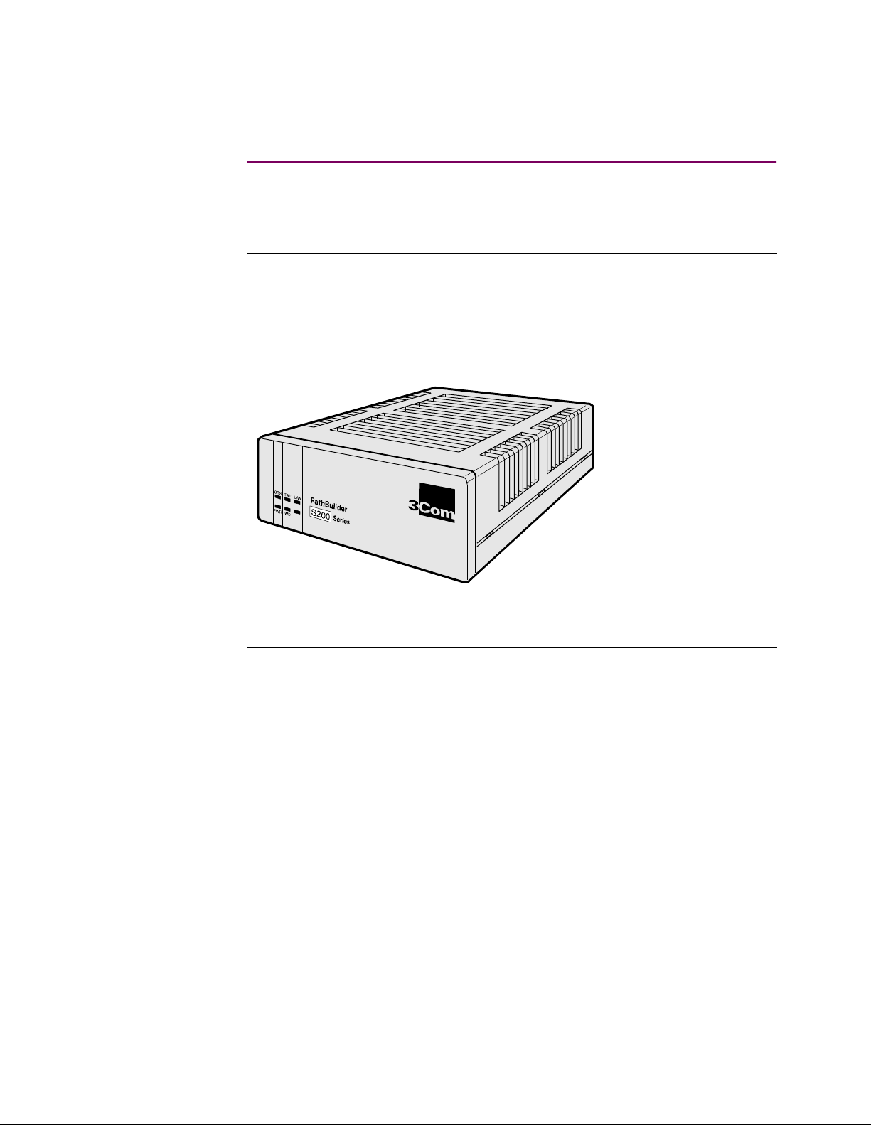
The 3Com PathBuilder S21x switch is a compact network access device for
connecting LAN and serial de vices to public and private networks servic es such as
frame relay and X.25. The PathBu ilder S21x switch is a desktop-size standalone
device suppor ting up to two optional daughtercards, a s shown in Figure 1-1. Using
the optional daughtercards, the PathBuilde r S21x s w itch o ffers a flexible and cost
effective solution for transporting data, voice, and video across a network.
®
Figure 1-1. The PathBuilder S21x Switch
About the PathBuilder S21x Switch 1-1
Page 14

Features
Features
Standard Features
CTP Port
Dual Daughtercard
Slots
Operating Software
The base PathBuilder S21x switch provides the following:
• External powe r supply
• Control Terminal Port (CTP) for local a nd remote configuration and
management
• Ethernet interface (10BaseT)
• One Serial DIM Port
• Two daughtercar d slots
• 2 MB FLASH and 4 MB DRAM
Port 4 can be used as a Control Terminal Port (CTP) for confi gurat ion, repor ting, a nd
troubleshooti ng the PathBuilder S21x switch. To set Port 4 as CTP, put the front
panel dip switch 4 into the UP position. To access the CTP you must also configure
your terminal or terminal emulati on software, to VT100, 9600 bps, 8 bit, no parity, 1
stop bit.
The PathBuilder S21x switch comes with two slots to support optional
daughtercards. This permits easy future expansion of the produc t.
Operating software is compressed in FLASH m emo r y and loaded into DRAM fo r
operation. The PathBuilder S21x switch supports these Applications Ware packages:
• IP Applications Ware Package
• IP & IPX Applications Ware Package
• SNA Applications Ware Package
• Serial Protocol Applic at ions Ware Package
• Multiservice Applications Ware Package
• Multimedia Applicati ons Ware Package
See the
unit for more information on the software availa ble for the PathBuilder S21x switch.
Software Release Notes
accompanying your PathBuilder S200 series switch
1-2 About the PathBuilder S21x S witch
Page 15

Daughterc ar d Func ti onalit y
Features
Introduction
Voice Relay
Daughtercard
Dual FXS Voice
Relay
Daughtercard
Remote Vu
Daughtercard
The PathBuilder S21x switch is available with the optional components listed below
factory-installed or as separate add-in daught ercards.
• Voice Relay Daughtercard
• Dual FXS Voice Relay Daughtercard
• RemoteVu Daughtercard
• DSU Daughtercard
• DIM Daughtercard
• DRAM SIMMs
Refer to the
(T0020) for informati on on the installation of optional daughtercards.
The PathBuilder S21x switch s upports the Voice Relay Daughtercard. This
daughtercard supports one voice channel, using either an analog FXS or FXO
interface. Bo th interfaces use RJ11 connectors.
The Dual FXS Voice Relay Daughtercard provides two FXS interface ports and
support one voice channel each. The FXS port uses RJ45 connectors.
The PathBuilder S21x switch supports video over Frame Relay using the RemoteVu
daughtercard. The RemoteVu Daughtercard provides two BNC connector, video
ports accepting NTSC, PAL or SECAM video sig nal standards a nd an RJ-45, RS232/
485 camera control port used for Pan/Tilt/Zoom (PTZ) camera control.
PathBuilder S200 Series Switch Daughtercard Installation Manual
DSU Daughtercard
About the PathBuilder S21x Switch 1-3
The DSU daughtercard functionality suits an extended range of 56 kbps
point-to- point DDS1 interfaces that conforms to AT&T 62310 or
ANSI T1E1.4/91-006.
The DSU is FCC Part 68 registered.
Diagnostic loopbacks from the telephone company are supported; local diagnostics
are activated from the CTP.
Page 16

Features
DIM Site
Daughtercard
DSU DIM
The DIM Site daughtercard provides optional V.24, V.35, V.36, or V.11 electrical
interfaces through a DB25 physical connector.
The PathBuilder S21x switch s upports the DSU DIM.
1-4 About the PathBuilder S21x S witch
Page 17

Software Functionali ty
Features
Introduction
Frame Relay & X.25
Service
RFC 877 and 1356
RFC 1490
Multiprotocol
Support
Depending on the operating software AppsWare package and optional daughtercard
installed the PathBuilder S21x switch can support the following functionality and
services.
The PathBuilder S21x switch pro vides se rial de vices with economi cal Etherne t LAN
access into public or private Frame Relay WAN. Where frame relay services are not
yet av ailable, the PathBuilder S21x switch can provide network acces s over X.25
services. When frame relay services becomes available, the PathBuilder S21x switch
can be easily configured and integrated to support frame relay. This fast migration
reduced network do wntime and protects hardware investments.
The PathBuilder S21x switch supports encapsulation of IP datagrams and other
network layer prot ocols over X.25 as specified in RFC 877 and RFC 1356. This
allows for interoperability with Front End Processors (FEPs) that support X.25 and
IP traff ic as well as router vendors suppo rt ing RFC 877/1356.
The PathBuilder S21x switch supports encapsulation of multiple protocols over
frame relay as specified by RFC 1490.
Support includes SDLC, Bisync, X.25, Async, IP/IPX, PPP, MLPPP, and Routing
and Bridging, as well as many other seria l protocols. Refer to the Software Release
Notice which acco mpanied your uni t f or a comple te list ing of pr otocols supporte d by
the PathBuilder S21x switch.
About the PathBuilder S21x Switch 1-5
Page 18
Target Application Environments
Target Applic atio n Environments
Introduction
LAN and Legacy
Protocol over
Frame Relay
Terminals
This section describes example applications for the PathBuilder S21x switch.
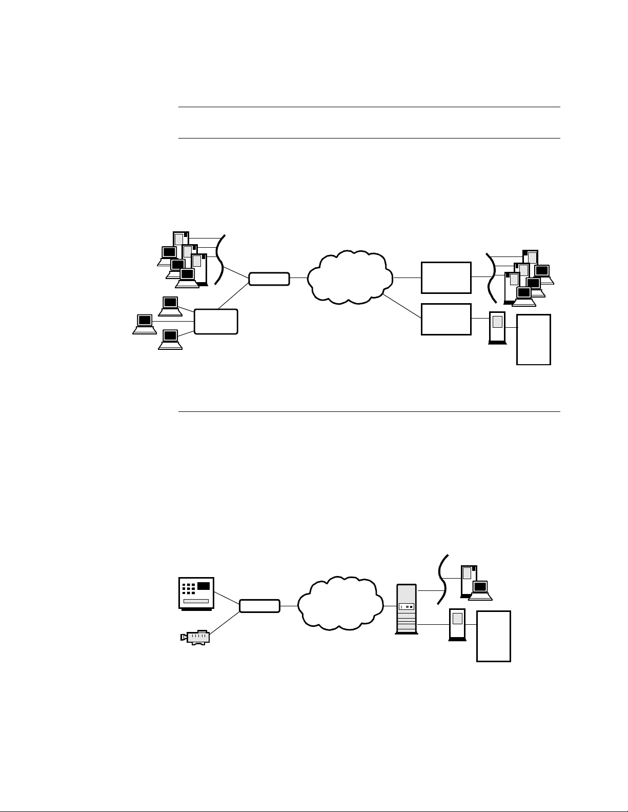
The PathBu ilder S21x switch supports multiprotocol encapsulation of IP tr affi c and
legacy serial protocols over frame relay as specified by RFC 1490. As shown in
Figure 1-2, a SNA cluster contr olle r co nnects to a s erial port on the P ath Builde r S 21x
switch and the Etherne t LAN connects to the 10BaseT Ether net port. The PathB uilder
S200 series switch is fully interopera ble with third party routers via RFC 1490.
Ethernet
Ethernet
Third Part y
Router
Third Party
Router
HOST
FEP
Cluster
Controller
PB S200
Frame Relay
Figure 1-2. LAN and Legacy Protocol over Frame Relay
Video and Legacy
Protocols over
Frame Relay Banking
Application
As shown in Figure 1-3, the PathBuilder S21x switch can support encapsulat ion of
video and legacy protocol over frame relay. This use of PathBuilder S21x switch
suits banking a pplication s suc h as Automat ed Bank Mac hines (ABMs) . W ith Dial on
Demand software feature enabled, the PathBuilder S21x switch initiates a connection
only when there is data transfe r, i.e. only for the durat ion of a bank transaction. The
RemoteVu Daughtercard can capture video and send video streams to the central
bank’s security system.
Central BankAutomated Teller Machine
PCs Running Hos t Video
Workstation Application
Bank ATM
Video
Camera
Equipped with
RemoteVu
Daughtercard
S200
Frame Relay
HOST
FEP
Figure 1-3. LAN and Legacy Protocol over Frame Relay
1-6 About the PathBuilder S21x S witch
Page 19
Target Application Environments
Branch Of fi ce to
Central Office over
Frame Relay
Branch Office
Ethernet
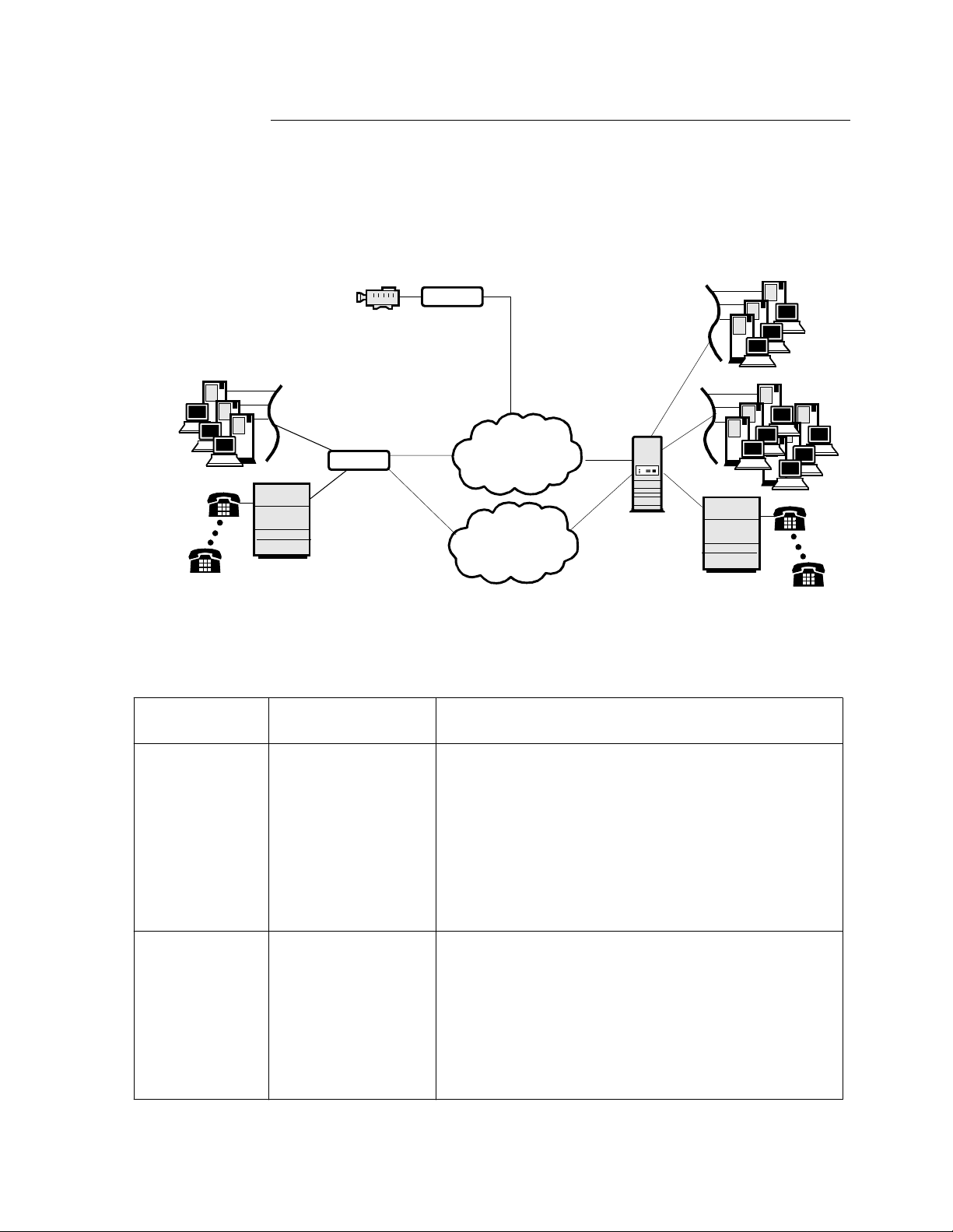
The PathBuilder S21x switch offers an ideal solution for branch office to central
office connectivity over a private or public frame relay network as shown in
Figure 1-4.
Security Monitoring
at Branch Of fice
Equipped with
RemoteVu Daughtercard
Vide o Ca me ra
Equipped with DSU DIM,
Voice Relay, and ISDN
Daughtercards
PB S200
PBX
PB S200
Frame Relay
ISDN
Centra l O ffic e
PCs Runnin g H ost Video
Workstation Appl ic ation
Ethernet
PBX
Application
Type
Branch acc ess to
Central Off ice
Security
Monitoring at
Branch Office
Figure 1-4. PathBuilder S21x switch supporting Voice and Video over
Frame Relay
Daughtercard
Application Description
Used
DSU DIM and Voice
Relay Daughtercards
The PathBuilder S21x switch supports voice, video and
data traff ic between the branch and cent ral of fi ce ov er private or public frame relay network. The Voice Relay
Daughtercard supports telephones, PBX, and faxes.
Connect a telephone or PABX to one FXS port on the
Voice Relay Daughtercard and all branch telephones hav e
access to the central office PBX. This eliminates long
distance telephone charges between the branch and
central office.
RemoteVu and DSU
Daughtercards
The PathBuil der S21x switch equipped with a Remot eVu
Daughtercard provide s secur ity surveillance and remote
monitoring of the branch of fice location from the central
offi ce. The RemoteVu Daughtercard packetizes video
stream in IP and sends the data over the frame relay.
Security personnel at the central office can control the
branch office video camera from a PC running the Host
Vi deo Workstation application.
About the PathBuilder S21x Switch 1-7
Page 20

Target Application Environments
1-8 About the PathBuilder S21x S witch
Page 21

Overview
Chapter 2
Installing the PathBuilder S21x Switch Har dware
Introduction
Follow These Steps
This chapter covers the installation of PathBuilder S21x switch hardware.
This table lists the ste ps y ou need to p erform and shows you where to look for
information on installing the PathBuilder S21x switch :
Step To Perform This Action See This Procedure
1
Check the contents of the
shipping package to make sure
everything is included.
2
Choose a site for the PathBuilder S21x switch.
3
Connect cables for the P athBuilder S21x switch.
4
Set the front panel dip switches
if required.
5
Installing Optional Daughtercard.
6
Installing or Remo ving the Lithium Battery
“Checking Your Shipment Contents”
section on page 2-2.
“Choosing a Site” section on page 2-3.
“Cabling the PathBuilde r S21x Switch”
section on page 2-5.
“Front Panel Dip Switches” section on
page 2-10
“Installing Optiona l Daughtercards”
section on page 2-11
“Installing or Removing the Lithium
Battery” section on page 2-12
Warning
The following special notices apply to all equipment handling procedures in this
manual.
Warning
Ports capable of connecti ng to port s on other app aratus are defined as Safety Extra
Low Voltage (SELV). To conform with EN60950, e nsure that these ports are only
connected to ports of the same type on other apparatus.
Avertissement
Les ports qui sont susceptib les d’être connectés à des équipements sont désignés
comme TBTS. Pour garantir la conformité à la norme EN 60950, n’interconnecte
ces ports qu’avec des ports du même type sur des autres matériels.
Warnung
Anschlusse, die mit anderen Geraten verbindet werden konnen, sind als SELV
beschrieben. Um Konformitat mit EN 60950 zu versichern, sic hern Sie es, daß diese
Anschlusse nur mit den des selben Type auf anderen Geraten verbindet werden.
Insta ll in g the Path B u ilder S 2 1x S w it ch H a r d w ar e 2-1
Page 22

Checking Your Shipm ent Contents
Pathbui lder S21x switch
PathBuild er S21x Installation Manual
RJ45 to DB25 CTP Cable
PathBuilder S200 Series User Guides CD-ROM
External P ower Supply and Cable
DIM Extraction Tool
Software Release Notice
®
®
Checking Your Shipment Content s
List of Contents
Before you install the PathBuilder S21x switch hardware, make sure your shipment
contents are complete. Inside your shipping carton, you should find the contents
shown in Figure 2-1.
Figure 2-1. PathBuilder S21x Switch Shipment Contents
In Case of Damage
or Missing Parts
2-2 Installing the Pa thBuilder S21x Switch Hardwa re
If the equipment is damaged, contac t the shipper . I f you have additional concerns
about damaged or missing parts, contact your nearest 3Com representative.
Page 23

Choosing a S ite
Choosing a Site
Introduction
Choosing a Site
This section describes how to choose a site for the PathBuilder S21x switch.
Choose a site within an appropriate distance of a power source. The selec ted site
should be free of accumulate d dust and environmental extremes.
Caution
All PathBuilder S200 series switch products should be used in environments
designed for computers and electr onic equipment. In areas susceptible to lightning,
take precaut ions to prevent damage to elec tronic equipment. Contact your telephone
company or an elec tronic accessories vendor for information on lightning protection
equipment. If you experience problems caused by surges from lightning, install
appropriately r ated surge suppressors on powe r and data lines connected to your
PathBuilde r S200 series switch.
Mise en Garde
Tous les produits PathBuilder S200 series switch doivent être utilisés dans des
environnements conçus pour les ordinateurs et équipements électroniques. Dans les
zones sujettes à la foudre, prenez soin de protéger l’équipement électronique contre
tout dommage. Con tactez vot re c ompagnie de télé phone ou un v ende ur d’a ccessoir es
électroniques pour de plus amples informations sur les équipements de prot ection
contre la foudr e. Si vous ave z des problèmes engendr és par des surtensions due s à la
foudre, installez des protections contre les surintensités appropriées sur les ligne s
d’alimentation e t de données connectées à votre produit P athBuilder S200 series
switch.
Power Source
Cable Clearance/
Air Circulation
Vorsicht
Alle PathBuil der S200 Series Switch-Produkte sollten in für Computer und
elektronisc he Geräte geeigneten Umgebungen ve r wendet werden. In durch
Blitzschlag gefährdeten Gebieten sollten Vorsichtsmaßnahmen zum Schutz von
elektronisc hen Geräten ergrif fen werden. Informationen über Schutz ei nrichtungen
gegen Blitzsch la gg efahr erh al ten Si e von Ihrer Telefongesellschaft oder vom
Einzelhandel für Elektrozubehör . Wenn Sie durch Blitzeinwirkung verursachte
Spannungsstörungen feststellen, installieren Sie einen ausreichend abgesicherten
Spannungsableit er an d en Strom - und Date nleitun gen, di e mit dem Pa thBuild er S200
Series Switch-Produkt verbunden sind.
Depending on your application and the country in which the PathBuilder S21x
switch will operate, a powe r source must be a grounded 100 to 240 VAC outlet.
Allow at least 12 inches (30.5 cm) in back of the unit for interfacing cable clearance
and air circulation, as shown in Figure 2-2.
Insta ll in g the Path B u ilder S 2 1x S w it ch H a r d w ar e 2-3
Page 24

Choosing a Site
Caution
To avoid overheating the unit’s circuitry, you should never place anything on top of
the unit, within 1 inch (2.5 cm) of the ventilation slots on the front panel, or within
12 inches (30.5 cm) of the back of the unit.
Mise en Garde
Afin d’évi ter toute s urchauf f e de s circ uits de l’unit é, ne placez a ucun obj et sur l’un ité
à moins de 2,5 cm (1 pouce) des cond uits de ventila tion du panneau avant et à moins
de 30,5 cm (12 pouces) de l’arrière de l’uni té.
Vorsicht
Zur Vermeidung einer Überhitzung der Geräteschaltkreise sollten Sie keine
Gegenstände auf dem Gerät plazi eren. Zu den Entlüftungsöffnungen der
Vorderabdeckung sollte ein Abstand von 2,5 cm und zur Rückseite des Gerätes von
30,5 cm eingehalten werden.
Minimum
12 inches
(30.5 cm)
Do Not Place
Anything on Top
of Unit
Figure 2-2. Proper Cable and Air Clearance
2-4 Installing the Pa thBuilder S21x Switch Hardwa re
Page 25

Cabling the PathBuilder S21x Switch
Cabling the PathBuilder S21x Switch
Introduction
PathBuilder S21x
Switch Rear Panel
After unpacking the PathBuilder S21x switch, you can connect the cables to
complete the hardware insta llation.
Figure 2-3 illustrates the rear panel of the PathBuilder S21x switch, optional
daughtercards, and the locations of cables that must be connected.
Caution
Connectors sho wing this symbol must not be connected to Published Switched
T elephone Networks (PSTN).
Mise en Garde
Les connecteurs marqués de ce symbole ne doivent pas être connecté s au rés eau
téléphonique commuté public (RTCP).
Vorsicht
Stecker mit diesem Symbol dürfen nicht an das öffentliche Telefonnetz (PSTN)
angeschlossen werden.
Insta ll in g the Path B u ilder S 2 1x S w it ch H a r d w ar e 2-5
Page 26

Cabling the PathBuilder S21x Switch
FXS FXSLOC
REM
Dual FXS Daughtercard
Two RJ11 connectors
for FXS Ports
RemoteVu Daughtercard
2 BNC and 1 RJ45
connector
POWER
FXS FXOLOC
REM
Voice Relay
Daughtercard
RJ11 connector for
FXS and FXO Ports
DSU Daughtercard
RJ48S connector for DSU
PORT 2
PORT 3
DIM Site
Daughtercard
DB25 connector for
V.24, V.35, V.36, V.11,
and DSU DIM
PORT 1PORT 2
PORT 1
CTP 10B-T
10BaseT
Ethernet
Cable
Power Supply
CTP Cable to an AS Y N C ter m in al.
DB25 connector for
V.24, V.35, V.36,
V.11, and DSU DIM
Figure 2-3. PathBuil der S21x Switc h Rear Pa nel and Cabl e Con nect ion s
2-6 Installing the Pa thBuilder S21x Switch Hardwa re
Page 27

Cables
Cabling the PathBuilder S21x Switch
Introduction
Port
Characteristics a nd
Cable
Requirements
This section describe s cable s required to connect to the PathBuilder S21x switch.
The table belo w lists the port characteristi cs, connector and cable requirements.
Port Connector Interface Cable Required Speed DCE/DTE
1 DB25 DIM Site Daugh-
tercard
V.1 1, V. 24, V.35,
V.3 6
DIM Site Daughtercard
DSU DIM
DB25-to-DB25
Cable
DSU/EIM Cable
Assembly and
Lease Line T elco
Cable shipped wit h
Integral DSU only
V.11, V.35 and V.36 Max. sync speed 2
mpbs
V.24 - Max. sync
speed 80 kpbs, Max
async speed 115.2
kbps
DSU - 56 kbps DTE DSU
Selectable
RJ48S DSU
Daughtercard
RJ11 Voice Relay
Daughtercard
RJ45 S/T
Daughtercard
BNC video
connector
RJ45
connector
RJ45 Dual FXS
RemoteVu
Daughtercard
RemoteVu
Daughtercard
Daughtercard
DSU Te lco Cable
shipped with DSU
Daughtercard
RJ11-to-RJ11
Cable
RJ45-to-RJ45
Cable
BNC-to-BNC
Cable
RJ45-to-RJ45
Cable
RJ45-to-RJ45
Cable
DSU -56 kbps DTE DSU
N/A N/A
Either 56 or 64 kbps
for each B Channel
and 9.6 kbps for the
D Channel
N/A
Insta ll in g the Path B u ilder S 2 1x S w it ch H a r d w ar e 2-7
Page 28

Cabling the PathBuilder S21x Switch
Port Connector Interface Cable Required Speed DCE/DTE
2 DB25 DIM Site Daugh-
tercard
V.11, V.24, V.35,
V.36
DIM Site Daughtercard
DSU DIM
RJ48S DSU
Daughtercard
RJ11 Voice Relay
Daughtercard
BNC video
connectors
RemoteVu
Daughtercard
DB25-to-DB25
Cable
DSU/EIM Cable
Assembly and
Lease Line Telco
Cable shipped with
Integral DSU only
DSU Te lco Cable
shipped with DSU
Daughtercard
RJ11-to-RJ11
Cable
BNC-to-BN C
Cable
V.11, V.35 and V.36 -
Selectable
Max. sync speed 2
mpbs
V.24 - Max. sync
speed 80 kpbs, Max
async speed 115.2
kbps
DSU - 56 kbps DTE DSU
DSU -56 kbps DTE DSU
N/A N/A
RJ45 connector
RJ45 Dual FXS
3 DB25 V.11, V.24, V.35,
RemoteVu
Daughtercard
Daughtercard
V.36 DIM
Integral DSU
DIM
RJ45-to-RJ45
Cable
RJ45-to-RJ45
Cable
DB25-to-DB25
Cable
DSU/EIM Cable
Assembly and
Lease Line Telco
Cable shipped with
Integral DSU only
4 RJ45 CTP Port RJ45-to-DB25
CTP Cable shipped
with PathBuilder
S200 series switch
unit
V.11, V.35 and V.36 Max. sync speed 2
mpbs
V.24 - Max. sync
speed 80 kpbs, Max
async speed 115.2
kbps
DSU - 56 kbps
Max. async speed
115.2 kbps
Selectable
DCE
2-8 Installing the Pa thBuilder S21x Switch Hardwa re
Page 29

Cabling the PathBuilder S21x Switch
Port Connector Interface Cable Required Speed DCE/DTE
LAN RJ45 10BaseT 10BaseT Cross-
over cable
or
standard UTP cable
(RJ45-to-RJ45)
Cable and
Connector Pinouts
For more information on cable and connector pinouts, refer to Appendix B,
PathBuilder S21x Switch Cabling or to the Daughtercard Installation Guide for
information on the optiona l daug htercards.
Control Terminal
Port Cable
Use an RJ45 (male) to DB25 (female) cable that comes with the PathBuilder S21x
switch to connect to the Control Terminal Port (CTP). The PathBuilder S21x switch
defaults this por t to 9.6 kbps, 8 bits, no parity, 1 stop bit.
Note
If you plan to use a persona l computer to co nfi gure the P athB uilder S21x switch,
you may need to purchase a DB25 (male) to DB9 (female) adapter for the serial
port of your personal computer. The serial ports on most personal computers
require DB9 connectors.
10BaseT Ethernet
Cable
Follow the se guidelines for 10BaseT cable connections:
• If you are connecting to a 10BaseT Hub, use a standard UTP cable
(RJ45 to RJ45).
• If you are connecting directly to a personal computer or Workstation LAN
card, use the 10BaseT crossover cable shipped with your PathBuilder S21x
switch.
10Mbps
Interface Connector
U interface (North A me ri ca) RJ11
S/T interface (Europe) RJ45
Insta ll in g the Path B u ilder S 2 1x S w it ch H a r d w ar e 2-9
Page 30

Front Panel Dip Swi tch es
Fron t P an el Di p Swi tc hes
Introduction
Front Panel
Switches
Control Port Switch
Default s Port 3 to 9600 bps 8N1.
POWER
STATUS
TEST
WATCHDOG
This section describes the front panel dip switches on the PathBuilder S21x switch.
Figure 2-4 illustrates the switches found behind the front panel of the PathB uilder
S21x switch.
Default Node
To reset all configurable par am eters, put
switch in up posit io n a nd P ow er Cycl e (or
Reset), then put switch in down position
and Power Cycle (or Restart) again.
PORT
LAN 4 3 2 1
DATA OUT
DATA IN
1234
RESET
Port
RI
56
CTP-- PORT 4
TM
DIAG.
DFLT NODE
3 3
MB
Figure 2-4. PathBuilder S21x Switch Front Panel Switches
Front Panel DIP
Switch Se tti n g
The six DIP switches on the front panel are defined as follows:
Switch
Posn.
Switch
Name
Down Up
1 RI/TM Pin 22 - Ring Indicator DCE T e st Mode Input
2 MB/TM Pin 22 - Make Busy DTE Test Mode Input
3 N/A N/A N/A
4 CTP-Port 4 Normal operation Configure Port 4 as PAD
port
5 DIAG Normal operation Execute diagnostics
6 DFLT- NODE Normal operation Reset CMEM
configuration
2-10 Installing the Pa thBuilder S21x Switch Hardwa re
Page 31
Install ing Op tion al Da u ghter c ards
Installing Optional Daughtercards
Optional
Daughtercards
The PathBuilder S21x switch s upports the followin g optiona l daughtercards:
• Voice Relay Daughtercard
• Dual FXS Voice Relay Daughtercard
• RemoteVu Daughtercard
• DSU Daughtercard
• DIM Site Daughtercard
• Motherboard DIM Option
• DRAM SIMM Option
These daughtercards can be installed either in the factory or on-site. Refer to the
PathBuilder S200 Ser ies Daughtercar d Installation Gui de
complete daughtercar d installation instructions.
(Part Numbe r T0020) for
Caution
On-site installation of these optional daughtercards should be undertaken by trained
service technicians.
Mise en Garde
L’installation de ces cartes fille optionnelles doit être effectuée par des techniciens
expérimentés.
Vorsicht
Die Installatio n vor Ort dieser optionalen Zusatzkarten sollte von geschulte n
Kundendiensttechnikern durchgeführt werden.
Insta ll in g the Path B u ilder S 2 1x S w it ch H a r d w ar e 2-11
Page 32

Installing or Removing the Lithium Battery
Installing or Remo vi ng the L ithi um Batte ry
Introduction
This section expla ins how to replace the real time batte ry . The PathBuilder S21x
switch uses a lithium battery on the motherboard to maintain the node’s real-time
clock. The battery is not used to store the configuration memory.
You need to install a battery under the following conditions:
• before the battery runs down
Warning
Only qualifi ed service personnel should perform the procedure described in this
section. If the battery is installed incorrectly, it could explode afte r the PathBui lder
S200 series switch product is powered up, damaging the unit.
Avertissement
Seules des personnes quali f iées peuvent mettre en pra tique les procédures décrites
dans cette section. Si la batterie n’est pas correctemen t installée, elle risque
d’exploser après la mise en marche du produit PathBuilder S200 ser ies switch et
d’endommager l’unité.
Warnung
Die in diesem Abschnitt aufgeführ ten Vorgänge sollten ausschließlich von
qualifi ziertem Servicepersonal durc hgeführt werden. Wenn die Batterie
unsachgemäß install iert wird, kann sie nach dem Einschalten des PathBuilder S200
Series Switch-Produkts explodieren und das Gerät beschädigen.
Battery Type
Battery Disposal
Routine Battery
Replacement
Note
After install ing the batte ry, set the PathBuilder S21x swi tch’s date and time. This
is done via the CTP in the Update System Parameter menu.
Replace the lithium battery with lithium coin cell type CR2032 only. These can be
obtained where watch batteries are sold.
Dispose of the battery in compliance with applicable local regulations.
The lithium battery should be replaced every two year s. Follow the instruc tions in
Figure 2-6 to replace the battery.
2-12 Installing the Pa thBuilder S21x Switch Hardwa re
Page 33

Installing or Removing the Lithium Battery
Removing the Top
Cover
Refer to Figure 2-5 when removing the top cover and front panel and follow these
steps:
Step Action
1
Open front pa nel door by using a downward motio n to pull it towa rd
you and off.
2
Insert a flat-head screwdriver in the slot above each of the six snap
hinges on the sides of the unit and push downward. The hinges snap
out toward you.
3
Repeat Steps 1 and 2 for the remaining hinges.
4
Lift off the top cover.
Open and remove front
1
panel by unsnapping t he
panel from its tabs.
®
Repeat for all si x hinges
4
3
Release hing es
on each side.
Insert a flat-head screwdriver in the
2
slot above each of the six sn ap
hinge s on t h e s i d es of the unit and
push downward. The hinges snap
out toward you.
Figure 2-5. Removing Top Cover and Front Panel on
PathBuilder S21x Switch
Insta ll in g the Path B u ilder S 2 1x S w it ch H a r d w ar e 2-13
Page 34

Installing or Removing the Lithium Battery
Removing/
Installing the
Battery
Figure 2-6 shows how to install and replace the battery.
To remove the battery:
Using your fingers, pu s h th e re taining
tabs aside and pry the battery out of the
holder.
To install the bat t e ry :
Place th e battery in the holder, with th e
positive (+) side up, and press down until
the ret aining tabs click into place.
Retaining Tabs
Figure 2-6. Replacing the Battery
Battery
Battery Holder
2-14 Installing the Pa thBuilder S21x Switch Hardwa re
Page 35

Overview
Chapter 3
Po wering on the P athBuilder S21x Switch
Introduction
This chapter describes
• powering up the P athBuilder S21x switch
• interpretin g LED display for power up diagnostics
• accessing the CTP
Powering on the PathBuilder S21x Switch 3-1
Page 36

Powering On The PathBuilder S21x Switch
Po wering On T he P athBuilder S21x Switch
Introduction
Powering On the
PathBuilder S21x
Switch
This section describes the sequence of events when you power up the PathBuilder
S21x switch.
The PathBuil der S21x switch does not have a power switch on the unit. Follow these
steps to power on the PathBuilder S21x switch:
Step Action
1
2
Plug the DC output cable of the power supply into the power socket on
the PathBuilder S21x switch back panel.
Connect the power cord to the power supply outlet.
Warning
When powering down the unit, you should always unplug the power cord at the
power supply outl et. Do not remove the power cor d from the back of the unit.
Avertissement
Lors de l’arrêt de l’unité, débranchez toujours le cordon d’alimentation du bloc
d’alimentation. Ne le débranchez pas de l’arrière de l’unité.
Warnung
Nach dem Abschalten des Gerätes sollten Sie immer den Netzste cker des Gerätes aus
der Steckdose ziehen. Entfernen Sie nicht das Netzkabel von der Gerät erückseite.
Warning
Hazardous volt age from the telecommunications network may be acces sible on unearthed units. Disconnect all telecommunications cables before removing the main
lead from the power supp ly.
Avertissement
Des tensions dangereuses provenant des réseaux de télécommunication peuvent être
présentes s ur des unités qui ne sont pas r eliées à la terre. Déconnectez tous les c âbles
de télécommunicatio n avant de retirer le câble de secteur du bloc d’alimentation.
Warnung
An nicht geerdeten Geräten können gefährliche Spannungen vom
Telekommunikationsnetz anliegen. Trennen Sie alle Kabelverbindungen zum
T elekommunikation snetz, bevor Sie das Hauptnetzkabel aus der Steckdose ziehen.
3-2 Powering on the PathBuilder S21x Switch
Page 37

Powerup Dia gnostics
Powerup Diagnostics
Introduction
Front Cover LEDs
Detailed Front
Panel LEDs
Power On - GREEN
Power is on and all DC Voltages
are within specif ications.
This section describes diagnostics that run automatically when you power up the
PathBuilder S21x switch.
The three front cover LEDs on the PathBuilder S21x switch help you follow the
progress of the unit’s powerup. Figure 3-7 shows the front cov er.
PWR STS
Test Watchdog
TST
PathBuilder
WD
S200
®
Series
Status
Power
Figure 3-7. Front Panel of the PathBuilder S21x Switch
Figure 3-8 illustrates the detailed front panel LEDs located behind the front cover.
Status - GREEN
On: Softw are Runn in g
Off: Software Not Running (Hardware Fault)
Flashing (Slow):Software Download in Progress
Reset
Resets (restarts) the unit.
Watchdog -GREEN
On: Hardware or software failure. Press
Reset or Po w er Cycle to cl ear LED.
Off: Processor OK.
Test - RED
Indica tes status of test resu lts.
POWER
STATUS
LAN 4 3 2 1
TEST
WATCHDOG
PORT
DATA OUT
DATA IN
RESET
Port
RI
Data In - RED
On: Data Entering Port = SPACE
Off: Data Entering Port = MARK
Data Out - GREEN
On: Data Leaving Port = SPACE
Off: Data Leaving Port = MARK
CTP-- PORT 4
TM
DIAG.
DFLT NODE
3 3
MB
On: Test Failed
Off: Normal Condition
Flashing:Test in Progress
Figure 3-8. Detailed Front Panel LEDs
Powering on the PathBuilder S21x Switch 3-3
Page 38

Powerup Diagnostics
Pow er Up
Sequence
Hardware Failure
When the PathBuilder S21x swit ch po wer cord is plugged into the powe r supply
outlet, you will see the following powerup sequenc e:
Stage when... ...this indicates
1
2
POWER (GREEN) lights
turns on.
TEST (GREEN) comes on
PathBuilder S200 seri es switch is
receiving power.
Diagnostics executes for 30 seconds.
and blinks five times
3
ST ATUS (GREEN) comes on
and blinks at slow rate.
Indicates softwa re is being do wnloaded
from FLASH.
TEST/WATCHDOG
(ORANGE) light also re main
on.
4
STATUS (GREEN) light
stays off for up to 10 se conds,
Software is initial izing your system
configurat ion.
then turns green.
If the TEST light turns on and remains on, one or more of the diagnostic tests have
failed, indicating there is a hardware problem. Contact 3Com for possible repairs to
your PathBuilder S21x switch.
Diagnostic Failure
Pow erup F ail ure
If the TEST light does not blink at all, but the Status light is on, the diagnostic
software image is corr upte d. P erform a download of the software option bundle.
If the STATUS light blinks continuously, at a constant rate, the software bundle in
Flash memory is corrupted. Perform a cold load of the software option bundle. See
Software Installation and Coldloading Manual
the
(Part No. T0028) for more
information.
3-4 Powering on the PathBuilder S21x Switch
Page 39

Accessing the Control Termin al Port
Accessing the Control Terminal Port
Introduction
Procedure
Once you have powered on the PathBuilder S21x switch, you can access the Control
T erminal Port from the PC or terminal attached to the CTP port.
Note
This section does not provide all information about accessing the CTP. For more
information on accessi ng and usi ng the CTP refer to the
Manual
(Part Number T0113).
Basic Configuration
Follow these steps to access the PathBuilder S21x switch CTP Main menu:
Note
This procedure assumes that a PC or terminal is c onne cted to the PathBuilder
S21x switch using the CTP access cable.
Step Action
1
Set your terminal, or terminal emulation software, to VT100, 9600 bps,
8 bit, no parity, 1 stop bit.
2
3
<CR>
Type
until either an asterisk ( *) or the OK prompt appears.
When you see OK, type
.ctp
.
atds0 <CR>
. When you see the asterisk (*) type
The CTP banner will appear. If this banner does not appear, verify that
these steps hav e been followed correctly.
4
Type
<CR>
at the password prompt, if no password has been set.
CTP Access Via
Remote Telne t
Another way to c onnect to t he CTP, after the node is conf igured a nd op erational, is to
access remotely via your esta blished IP network by telneting into the node from an
IP network-based pe rs onal computer or workstation. You can connect to the CTP by
entering
CTP Access Via
Remote X.25 or
Frame Relay
Network
Powering on the PathBuilder S21x Switch 3-5
If the PathBuilder S21x switch is operating in an X.25 network, or if Frame Relay
Annex-G is used to connec t with other 3Com PathBuilder S200 series switches, you
can access the PathBui lder S200 series switch CTP remotely by making a Switched
Virtual Circuit (SVC) call to the node and specifying subaddress 98.
atds0 <CR>
after the PathBuilder S21x switch outputs the OK prompt.
Page 40

Page 41

Specifications
Appendix A
Specifications
Introduction
Hardware
Software
This section describes the physical and environmental specifications and power
requirements for the PathBui lder S21x switch product.
PathBuilder S21x switch products feature the following:
• 68360 processor
• 4 Mbytes DRAM (expandable to 8 or 12 Mbytes )
• 10Base T Ethernet
• Async Control Port
• 2.0 Mbytes of FLASH memory
• 2 optional daughtercard ports
• 1 configurabl e DIM port
The PathBuilder S21x switch s upports these software applic a tions ware:
• IP Applications Ware Package
• IP & IPX ApplicationsWare Package
• SNA Applications Ware Package
• Serial Protocol Applic at ions Ware Package
• Multiservice Applications Ware Package
• Multimedia Applicati ons Ware Package
Environmental
Electromagnetic
Compatibility
Specifications A-1
The followin g environmental condit ions are required:
• Operating temperat ure: 32° to 104°F maximum (0° to 40°C maximum)
• Storage temperature: -22° to +15 8°F (-30° to +70°C)
• Relative humidity: 5% to 95% (noncondensing)
PathBuilder S21x switch products adhere to the following:
• FCC Part 15, Cla ss B
• CISPR 22 and EN 55022, Class B
• AS 3548, Class B
• EN 50082-1
Page 42

Power
Requirements
PathBuilder S21x switch typically has the following power requirements:
• 100 to 240 VAC nominal at 47 to 63 Hz
• 32 watts input powe r (64 VA)
• maximum input current 0.7 amps
Pow er Supply
Description
Safety
Physical
PathBuilder S 21x switch products are powered by a switch mode power supply with
22.5 watts maximum output power .
PathBuilder S21x switch meets the following safety standards:
• EN60950
• CSA 950
• UL Listed per UL 1950
PathBuilder S21x switch has the following measurements:
• Height: 2.75 in. (6.7 cm)
• Length: 6.7 in. (17 cm)
• Width: 9.5 in. (24.5 cm)
• Weight: 2.2 lb (1.0 kg)
A-2 Specifications
Page 43

Overview
Appendix B
PathBuilder S21x Switch Cabling
Introduction
Daughtercard
Cable Information
Ordering Cables
This Appendix identifies the cables and pinout requirements for the PathBuilder
S21x switch. The following cables are describ ed in this ap pen d ix:
• CTP Access Cable
• Dual FXS Voice Relay Cable
• 10BaseT Crossover Cable
• RemoteVu Video Cables
• DSU Daughtercard Cable
• V.35/V.36 Cable
• V.11 Cable
• V.24 Cable
Cables for optional daughtercards are shipped with the daughtercards. If your
PathBuilder S 21x switc h is shipped wi th pre -install ed daug hterca rds you wi ll receive
the cables. For daughtercard installation and more cable information, please refer to
PathBuilder S200 Series Daughtercard Installation Guide
the
To order cables please contact a 3Com representative. In addition to the cables
listed abov e the following cables can be ordered:
• DB25 Male to M34 Female cable
• DB25 Male to M34 Male cable
(Part Number, T0020).
PathB u il d e r S21x Sw it ch Cab li n g B-1
Page 44

CTP Access Cable
CTP Access Cable
CTP Cable
Connector and
Pinout
Use the supplied RJ45/DB25 cable to conne ct to the CTP Port (Por t 4) and perform
CTP operations such as coldloading sof tware images into a PathBuil der S21x switch .
Port 4 is a DCE. This table identifies the pinout for this RJ-45 connector:
RJ45 Pin Signal Pin Connection
on DB25F
Adapter
1 (not connected) Request To Send (RTS) 4
2 DTE Ready (DTR) 20
3 Received Data (RXD) 3
4 (not connected) Data Carrier Detect (DCD) 8
5 Signal Ground 7
6 Transmitted Data (TXD) 2
7 Data Set Read y (DS R) 6
8 (not connected) Clear To Send (CTS) 5
B-2 PathBuilder S21x Switch Cabling
Page 45

Voic e Re la y C ab le
Voice Relay Cable
Specification
Connector Pinout
The voice relay cabl e ship ped with the Voice Relay Daughtercard has the following
specific ation:
• Connectors: RJ11 to RJ11 Cable
• Color: Gray
The RJ11 connectors for the FXO and FXS port have the following pinout:
Pin
No.
1N/A N/A
2 N/A Aux B External
3 Loop B Line B
4 Loop A Line A
5 N/A Aux A External
6N/A N/A
Name Function Name Function
FXS FXO
Handset
Handset
Warning!
The FXS Interface should only be connected to an analog telephone handset and/or
fax machine.
Warning!
The FXO Interface should only be connected to an analog PBX line.
Warning!
The PathBuilder S200 series switc h Voice Relay daughtercard has not been certified
for use in a PSTN.
PathB u il d e r S21x Sw it ch Cab li n g B-3
Page 46

Dual FXS Voice Relay Cable
Dual FXS Voice Relay Cable
Specification
Connector Pinout
The voice relay cabl e ship ped with the Dual FXS Voice Relay Daughtercard has the
following spe cification:
• Connectors: RJ45 to RJ45 Cable
• Color: Gray
The RJ45 FXS port have the following pinout:
Pin
No.
1N/A
2N/A
3 Loop B
4 Loop A
5N/A
6N/A
Name Function
FXS
Warning!
The FXS Interface should only be connected to an analog telephone handset and/or
fax machine.
B-4 PathBuilder S21x Switch Cabling
Page 47

10BaseT Crossover Cable
10BaseT Crossover Cable
Specifications
Connector Pinout
The 10BaseT cable shipped with the PathBuilder S21x switch has the following
specifications:
• Cable Type: Category 3 or better
• Connectors: RJ45 to RJ45
• Color: Gray
• Part Number: 61798-01
Four of the pins are used, as sho wn below:
Pin Pin
13
26
31
62
The connector pins are numbered ind icate d in the following diagra m:
L
Figure B-1. RJ45 Pinout
Pin 8
Pin 1
PathB u il d e r S21x Sw it ch Cab li n g B-5
Page 48

RemoteVu Video Cables
RemoteV u V ideo Cabl es
Introduction
RJ-45 Connector Camera Interface
Connector Pinout
The RemoteVu Daughtercard requires the following cables:
• RJ45-to-RJ45 Camera Interface Cable
• BNC-to-BNC Cable
This table describes the RJ-45 connector - camera interface connector:
Pin Function
1
EIA-232 data input
2
EIA-232 data output
3
EIA-485/422 positive data output
4
EIA-485/422 negative data output
5
EIA-485/422 negative data input
6
EIA-485/422 positive data input
7
+12V (curren t available = 50 mA)
8
Ground
B-6 PathBuilder S21x Switch Cabling
Page 49

DSU Daughtercar d Cab le
DSU Daughtercard Cable
DSU Daughtercard
Cable Pinout
The following table shows the pinouts for the RJ48S connector:
Pin Signal Function
1 TX - TIP
2 TX - RING
3 RX - TIP
4 RX -RING
PathB u il d e r S21x Sw it ch Cab li n g B-7
Page 50

V.35/V.36 Cable
V.35/V.36 Cable
V.35/ V.36 DCE
Cable Pinout
The followin g table shows the DCE pinouts forV.35 and V.36 cables.
Pin Function/Signal Name
1 SHIELD/FRAME GROUND
2 TRANSMITTED DATA A
3 RECEIVED DATA A
4 REQUEST TO SEND
5 CLEAR TO SEND
6 DATA SET READY
7 SIGNAL GROUND
8 DATA CARRIER DETECT
13 TRANSMIT CLOCK B
14 TRANSMITTED DATA B
15 TRANSMIT CLOCK A
16 RECEIVED DATA B
17 RECEIVE CLOCK A
18 RECEIVE CLOCK B
19 RECEIVE CLOCK B
20 DATA TERMINAL READY
21 TRANSMIT CLOCK B
22 EXTERNAL TRANSMIT CLOCK B
24 EXTERNAL TRANSMIT CLOCK A
25 (No Connection)
B-8 PathBuilder S21x Switch Cabling
Page 51

V.35/ V.36 Cable
V.35/ V.36 DTE
Cable Pinout
The followin g table shows the DTE pinouts forV.35 and V.36 cables.
Pin Function/Signal Name
1 SHIELD/FRAME GROUND
2 TRANSMITTED DATA A
3 RECEIVED DATA A
4 REQUEST TO SEND
5 CLEAR TO SEND
6 DATA SET READY
7 SIGNAL GROUND
8 DATA CARRIER DETECT
13 TRANSMIT CLOCK B
14 TRANSMITTED DATA B
15 TRANSMIT CLOCK A
16 RECEIVED DATA B
17 RECEIVE CLOCK A
18 RECEIVE CLOCK B
19 RECEIVE CLOCK B
20 DATA TERMINAL READY
21 TRANSMIT CLOCK B
22 EXTERNAL TRANSMIT CLOCK B
24 EXTERNAL TRANSMIT CLOCK A
25 TEST MODE
(V.36 ONLY).
PathB u il d e r S21x Sw it ch Cab li n g B-9
Page 52

V.11 Cable
V.11 Cable
V.11 DCE Cable
The followin g table shows the DCE pinouts for the V.11 cable.
Pin V.11 Function/Signal Name
1 SHIELD/FRAME GROUND
2 T (A) TRANSMITTED DATA A
3 R (A) RECEIVED DATA A
4 C (A) CONTROL A
6 I (B) INDICATION B
7 SIGNAL GROUND
8 I (A) INDICATION A
13 S (B) TRANSMIT CLOCK B
14 T (B) TRANSMITTED DATA B
15 S (A) TRANSMIT CLOCK A
16 R (B) RECEIVED DATA B
17 * RECEIVE CLOCK A
18 * RECEIVE CLOCK B
19 * RECEIVE CLOCK B
20 C (B) CONTROL B
21 S(B) TRANS MIT CLOCK B
22 X (B) EXTER NAL TRANSMIT CLOCK B
24 X (A) EXTERNAL TRANSMIT CLOCK A
*These V.11 signals are not used in the X.21 stan dard.
B-10 PathBuilder S21x Switch Cabling
Page 53

V.11 Cable
V.11 DTE Cable
The followin g table shows the DTE pinouts for the V.11 cable.
Pin Function/Signal Name
1 SHIELD/FRAME GROUND
2 TRANSMITTED DATA A
3 RECEIVED DATA A
4 CONTROL A
6 INDICATION B
7 SIGNAL GROUND
8 INDICATION A
13 TRANSMIT CLOCK B
14 TRANSMITTED DATA B
15 TRANSMIT CLOCK A
16 RECEIVED DATA B
17 RECEIVE CLOCK A
18 RECEIVE CLOCK B
19 RECEIVE CLOCK B
20 CONTROL B
21 TRANSMIT CLOCK B
22 EXTERNAL TRANSMIT CLOCK B
24 EXTERNAL TRANSMIT CLOCK A
PathB u il d e r S21x Sw it ch Cab li n g B-11
Page 54

V.24 Cable
V.24 Cable
V.24 DCE Cable
The followin g table shows the DCE pinouts for the V.24 cable. These pins are
assigned double functions in the V.24 cable:
• Pin 15: Outputs TRANSMIT CLOCK if the port is configured for internal
clocks. Otherwise it acts as a V.54 Loop 3 signal when connected to a modem.
• Pin 22: Used as the Ring Indic ator output i f t he port is c onf igure d to emu late a
dial modem. For this to work properly, the RI/TM switch of the port must be
set to RI. When the RI/TM switch is set to TM, this pin acts as an input, and
the TM output from the attached modem (pin 25 on the modem) comes into
the 6500 on this pin.
Pin Function/Signal Name
1 Shield/Frame Ground
2 TXD
3RXD
4RTS
5CTS
6DSR
7 Signal Ground
8DCD
14 DATA RESTRA I N T
15 TRANSMIT CLOCK or V.54 Loop 3 *
16 STANDBY INDICATOR
17 RECEIVE CLOCK
18 EXTERNAL RECEIVE CLOCK
20 DTR
21 V.54 Loop 2
22 RI/TM *
24 EXTERNAL TRANSMIT CLOCK
25 TEST MODE
B-12 PathBuilder S21x Switch Cabling
Page 55

V.24 Cable
V.24 DTE Cable
The followin g table shows the DTE pinouts for the V.24 cable.
Pin Function/Signal Name
1 Shield/Frame Ground
2 TXD
3RXD
4RTS
5CTS
6DSR
7 Signal Ground
8DCD
14 DATA RESTRA I N T
15 TRANSMIT CLOCK
16 STANDBY INDICATOR
17 RECEIVE CLOCK
18 EXTERNAL RECEIVE CLOCK or V.54 Loop 3 *
20 DTR
21 V.54 Loop 2
22 (No Connection)
24 EXTERNAL TRANSMIT CLOCK
25 MAKE BUSY
PathB u il d e r S21x Sw it ch Cab li n g B-13
Page 56

V.24 Cable
B-14 PathBuilder S21x Switch Cabling
Page 57

In This Appen dix
Appendix C
Troubleshooting Your PathBuilder S21x Switch
Introduction
This appendix describes some of the actions you can take to correct problems you
may be having with your PathBuilder S21x switch.
Tro ubleshooting Your PathBuilder S21x Switch C-1
Page 58

While Setting Up Y our Configuration
While S ett ing Up Your Configurat io n
Introduction
This section describes the ways you can use to isolate problems that you may
encounter while setting up a PathBuilder S21x switch to pass IP traffic over PPP
links. For discussion purposes, the following network configuration (shown in
Figure C-1) is assumed.
Note
The configuration of the local PathBuilder S21x switch and the number to call
can be obtained by defaulting the node—selecting “Default Node” from the
CTP’s Main menu.
10.10.10.0
Your Local
Network
10.10.10.1
Local
PB S200
(905) 555 -6666
10.10.20.1
Network
10.10.20.2
Remote
PB S200
(905) 555-1234
10.10.30.0
Remote
Network
Figure C-1. Network Configuration
Note
The IP addresses use d in this configuration example are for illustration purposes
only. You must obtain registered IP addresses fr om your netw ork administrator
or your Internet Servic e provider, and configure them in your PathBuilder S21x
switch before connect ing to the Internet or Intranet.
Checking the
Physical
Use these procedures to check your PathBuilder S200 series switch connection and
interface:
Connection
Step Action
1
Ensure that the STS LED is ON to confirm that power is connected and
that the uni t is working. ( Other LEDs may be ON or blink occasionally.)
2
If the STS LED flashe s continuously for more than 30 seconds a fter the
power is applied, the software image in the flash is corrupted and the
node is waiting for software to be coldloaded. Refer to the Software
Installation and Coldloading Manual
for more infromation on cold-
loading software.
3
If you are connected to the control port using an async terminal, (9600
bps, 8 bits, no parity), type “AT <CR>” and confirm that the PathBuilder S200 series switch outpu ts “OK.” Then log into the CTP.
C-2 Troubleshooting Your PathBuilder S21x Sw itch
Page 59

While Setting Up Your Configuration
Pinging the Local
LAN Interface
From the workstation or PC connect ed to the same loca l LAN segment that the
PathBuilder S21x switch is connected to, ping the LAN interface of the PathBuilder
S200 series swi tch (“ping 10. 10.10.1”) . The LAN LED should f lash whe ne v er a Ping
packet is received.
If the LAN LED does not flash, check the configur ation of the PC and the LAN
connection and do the following:
Step Action
1
Check the IP address and IP address mask of your PC or workstation,
making sure that they are set to valid address and mask appropriate for
your local subnetwork. (In the above example, the IP address of the PC
must be set betwee n 10.10. 10.2 an d 10.10.1 0.254 ) and the address mask
must be set to 255.255.255.0).
2
Check the statistics of the LAN port (port 5) of the local node , making
sure that the “Carrier” says “Present”. If the “Carrier” fie ld displays
“Lost”, there is a problem with your LAN connection and you should do
the following:
• If you are using a BNC connection between your workstat ion/P C
and the PathBuilder S21x switch, make sure that you put in the 50
Ω
termination resistors at both ends of the line.
• If you are connecting your LAN using the 10BaseT and a 10BaseT
Hub, check the display at the Hub to ensure that the connec tion
between PathBuilder S21x switch and the Hub is correct. (Most
Hubs have LEDs that stay ON when the carrier is detected).
• Change the RJ45 twisted pair cable between PathBuilder S200
series switch and your Hub as it may be damaged. A straightthrough 10BaseT cable is generally required between PathBuild er
S21x switch and a 10BaseT Hub.
If there is only a sin gle PC or work station connecting to the PathBu ilder
S200 series switch, and you are not using a 10BaseT Hub, ensure that
you have used the RJ45 crosso ver cable, shipped with your PathBui lder
S21x switch, to connect between the PC and the Path Builder S200
series switch.
If the LAN LED does flash, but there is no ping respo nse, do the following:
Step Action
1
From the CTP, check the stati stics of the LAN port ( Port 5) (se lect menu
option Statistics, and select port 5) while sending ping packets.
2
Confirm that the Rx Frame Count, in the Data Summary, increases as
the ping packet arrives.
3
Check the Tx Frame Count field in the Data Summary part of the LAN
port statisti cs. If the field increases for every ping packet it receives, t he
LAN and the configuration should be working.
Tro ubleshooting Your PathBuilder S21x Switch C-3
Page 60

While Setting Up Y our Configuration
Step Action
4
If the RX Frame count increases, but the Tx Frame Count does not, the
problem is most likely due to misconfiguration in t he IP router I nterf ace
#1. Make sure that the IP addresses and IP address mask (select menu
option Router -> IP Interfaces -> Interface 1) are set proper ly.
Pinging the Local
WAN Interface
Once you are successful in getting ping responses from the local LAN i nterface, you
can proceed to ping the local WAN interface (“ping 10.10.20.1” in the example). If
there is no response, then check the following:
Step Action
1
Confirm that the IP interfaces (either 5 or 6) of the WAN link that you
are trying to ping are configured for Enable. (Select menu item
Router->Con figu re Inter face St at es. )
2
Confirm that th e IP add res s and IP ad d re ss ma sk o f the WAN interface
you are pinging are confi gur ed properly.
C-4 Troubleshooting Your PathBuilder S21x Sw itch
Page 61

Appendix D
T echnical Support
3Com provides easy access to technical support information through a variety of
services. This appendix describes these services.
Information cont ained in this appendix is corr ect a t time of publication. For the very
latest, 3Com recommends that you acces s the 3Com Corporation W orld Wide Web
site.
Online Technical
Services
W orld Wide W eb
Site
3Com FTP Site
3Com offers worldwide product support 24 hours a day, 7 days a week, through the
following online systems:
• World Wide Web site
• 3Com FTP site
• 3Com Bulletin Board Service (3Com BBS)
•3ComFacts
Access the l atest ne tw orking i nformation on t he 3Com C orpor ation World Wide Web
site by enterin g the URL into your Inte rnet browser:
http://www.3com.com/
This service provide s access to online support information such as technical
documentation and softw a re library , as well as support options ranging from
technical education to maintenance and professional servic es.
Download drivers, patches, and software, across the Internet from the 3Com public
FTP site. This service is available 24 hours a day, 7 days a week.
To connect to the 3Com FTP site, enter the following information int o your FTP
client:
• Hostname:
• Usernam e:
• Password:
SM
automated fax service
ftp.3com.com (or 192.156.136.12)
anonymous
your Internet e-mai l address>
<
Note
A user name and password are not needed with Web browser software such as
Netscape Naviga tor and Internet Explorer.
Technical Support D-1
Page 62

3Com Bulletin
Board Service
The 3Com BBS contains patches, software , a nd drivers for 3Com products. This
service is available through analog modem or digital modem (ISDN) 24 hour s a day,
7 days a week.
Access by Analog Modem
To reach the service by modem, se t your modem to 8 data bits, no parity, and 1 stop
bit. Call the telephone number nearest you:
Country Data Ra te Telephone Number
Australia Up to 14,400 bps 61 2 9955 2073
Brazil Up to 14,400 bps 55 11 5181 9666
France Up to 14,400 bps 33 1 6986 6954
Germany Up to 28,800 bps 4989 62732 188
Hong Kong Up to 14,400 bps 852 2537 5601
Italy Up to 14,400 bps 39 2 27300680
Japan Up to 14,400 bps 81 3 3345 7266
Mexico Up to 28,800 bps 52 5 520 7835
P.R. of China Up to 14,400 bps 86 10 684 92351
3ComFacts
Automated Fax
Service
Support from Your
Network Supplier
Taiwan,
Up to 14,400 bps 886 2 377 5840
R.O.C.
U.K. Up to 28,800 bps 44 1442 438278
U.S.A. Up to 28,800 bps 1 408 980 8204
Access by Digital Modem
ISDN users can dial in to the 3Com BBS using a digital modem for f ast access up to
56 Kbps. To access the 3Com BBS using ISDN, use the following number:
1 408 654 2703
The 3ComFacts automated fax service provides technical articles, diagrams, and
troubleshooting instructions on 3Com products 24 hours a day, 7 days a week.
Call 3ComFacts using your Touch-Tone telephone:
1 408 727 7021
If additional assistance is required, contact your network supplier. Many suppliers
are authorized 3Com servic e part ners who are qualified to pro vide a variety of
services, including network planning, installation, hardware maintenance,
application training, and support services.
When you contact your network supplier for assistance, have the following
information ready:
• Product model name, part number, and serial number
• A list of system hardware and software, including revision leve ls
• Diagnostic error messages
• Details about recent configuration changes, if applicable
D-2 Technical Support
Page 63

If you are unable to contact your network supplier , see the following section on how
to contact 3Com.
Support from
3Com
If you are unable to obtain assistance from the 3Com online technical resources or
from your network supplier, 3Com offers technical telephone support services. To
find out more about your support options, please call the 3Com technical telephone
support phone number at the location nearest you.
When you contact 3Com for assistance, have the following information ready:
Below is a list of worldwide technical telephone support num bers:
Country Telephone Number Country Telephone
Asia Pacifi c Rim
Australia
Hong Kong
India
Indonesia
Japan
Malaysia
New Zealand
Pakistan
Philippines
Europe
From anywhere in Europe,
call:
• Product model name, part number, and serial number
• A list of system hardware and software, including revision leve ls
• Diagnostic error messages
• Details about recent configuration changes, if applicable
Number
1 800 678 515
800 933 486
61 2 9937 5085
001 800 61 009
0031 61 6439
1800 801 777
0800 446 398
61 2 9937 5085
P.R. o f Ch i na
Singa pore
S. Korea
From anywhere in S. Ko rea:
From S eou l:
Taiwan, R.O.C.
Thailand
10800 61 00137 or
021 6350 1590
800 6161 463
82 2 3455 6455
00798 611 2230
0080 611 261
001 800 611 2000
1235 61 266 2602
+31 (0)30 6029900 phone
+31 (0)30 6029999 fax
From the following Europea n countries, you may use the toll-free numbers:
Austria
Belgium
Denmark
Finland
France
Germany
Hungary
Ireland
Israel
Italy
06 607468
0800 71429
800 17309
0800 113153
0800 917959
0130 821502
00800 12813
1 800 553117
177 3103794
1678 79489
Netherlands
Norway
Poland
Portugal
South Africa
Spain
Sweden
Switzerl and
U.K.
0800 0227788
800 11376
0800 3111206
05 05313416
0800 995014
900 983125
020 795482
0800 55 3072
0800 966197
Latin Am erica
Argentina
Brazil
North America
541 312 3266
55 11 523 2725, ext. 422
1 800 NET 3Com
Colombia
Mexico
571 629 4847
01 800 849 2273
(1 800 638 3266)
Technical Support D-3
Page 64

Returning
Products for Repair
Before you send a product direc tly to 3Com for repair, you must first obta in a Return
Materials Authoriza tion (RMA) number . Produc ts se nt to 3Com without RMA
numbers will be returned to the sender unopened, at the sender’s expense.
To obtain an RMA number, call or fax:
Country Telephone Number Fax Number
Asia, Pacific Rim 65 543 6342 65 543 6348
Europe, South Africa, and
011 44 1442 435860 011 44 1442 435718
Middle East
From the following European countries, you may call the toll-free numbers; select
option 2 and then option 2:
Austria
Belgium
Denmark
Finland
France
Germany
Hungary
Ireland
Israel
Italy
Netherlands
Norway
Poland
Portugal
South Africa
Spain
Sweden
Switzerl and
U.K.
06 607468
0800 71429
800 17309
0800 113153
0800 917959
0130 821502
00800 12813
1800553117
177 3103794
1678 79489
0800 0227788
800 11376
00800 3111206
05 05313416
0800 995014
900 983125
020 795482
0800 55 3072
0800 966197
D-4
Latin America 1 408 326 2927 1 408 764 6883
U.S.A. and Canada 1 800 876 3266, option 2 1 408 764 7120
3/26/98
Page 65

Index
Numerics
10Base2 Ethernet cable 2-9
10BaseT Ethernet cable 2-9
15637
ChapTitle
PathBuilder S21x Series Switch 2-1
3Com bulletin board servic e (3Com BBS) 2
3Com URL 1
3ComFacts 2
A
air circulati on 2-3
Audience v
B
Battery
disposal 2-12
replacement schedule 2-12
replacement type 2-12
bulletin board servic e 2
C
E
Electromagnetic spe cifications A-1
Environmental speci fications A-1
F
fax service (3Co m Fa ct s ) 2
Front Panel 3-3
I
Installing
PathBuilder S21x Switch 2-5
L
List of parts 2-2
M
Missing parts
what to do 2-2
Multiprotocol support 1-5
N
Cable
10BaseT 2-9
cable
clearance 2-3
Cables 2-5
location 2-5
Cabling
10Base2 2-9
10BaseT 2-9
DECconnect pinout specific a tions B-2
caution, definition v
Configuration
troubleshooting during C-2
CTP
cable 2-9
description 1-2
CTP Por t 1-2
D
Daughtercard
Dual Slots 1-2
Daughtercards 1-2
DSU 1-3
options 2-11
DSU daughtercard
overview 1-3
network supplier support 2
O
online technical services 1
Ordering information
PathBuilder S200 Series User Guides ix
Overview of contents vii
P
Parts list 2-2
PathBuilder S200 Series User Guides ix
PathBuilder S21x Switch
configuration 2-5
installing 2-5
Shipment Contents 2- 2
Top Cover Removal 2-13
unpacking 2-5
Physical specifi cations A-2
power
source 2-3
Power requirements A-2
Powering on 3-2
Powerup
diagnostics 3-2, 3-3
FLASH memory corruption 3-4
Index-1
Page 66

hardware failure 3-4
software failure 3-4
power-up 3-2
Diagnostics 3-3
R
returning products f or repair 4
RFC 877
description 1-5
S
Safety specifications A-2
site preparat ion 2-3
Special notices
description v
Specifications
electromagnetic A-1
environmental A-1
physical A-2
power requi rem en ts A-2
safety A-2
T
technical support
3Com URL 1
bulletin board servic e 2
fax service 2
network suppliers 2
product repair 4
Troubleshooting C-1
configuration C-2
U
Unpacking
parts list 2-2
URL 1
V
Vanguard 320 1-1
overview 1-1
W
warning, definition v
World Wide Web (WWW) 1
Index-2
 Loading...