

Page 1

3Com Switch 8800
Configuration Guide
www.3com.com
Part No. DUA1750-2BAA01
Published: December 2005
Page 2

Copyright © 2005, 3Com Corporation. All rights reserved. No part of this documentation may be reproduced in any form or by
any means or used to make any derivative work (such as translation, transformation, or adaptation) without written permission
from 3Com Corporation.
3Com Corporation reserves the right to revise this documentation and to make changes in content from time to time without
obligation on the part of 3Com Corporation to provide notification of such revision or change.
3Com Corporation provides this documentation without warranty, term, or condition of any kind, either implied or expressed,
including, but not limited to, the implied warranties, terms or conditions of merchantability, satisfactory quality, and fitness for a
particular purpose. 3Com may make improvements or changes in the product(s) and/or the program(s) described in this
documentation at any time.
If there is any software on removable media described in this documentation, it is furnished under a license agreement included
with the product as a separate document, in the hard copy documentation, or on the removable media in a directory file named
LICENSE.TXT or !LICENSE.TXT. If you are unable to locate a copy, please contact 3Com and a copy will be provided to you.
UNITED STATES GOVERNMENT LEGEND
If you are a United States government agency, then this documentation and the software described herein are provided to you
subject to the following:
All technical data and computer software are commercial in nature and developed solely at private expense. Software is
delivered as “Commercial Computer Software” as defined in DFARS 252.227-7014 (June 1995) or as a “commercial item” as
defined in FAR 2.101(a) and as such is provided with only such rights as are provided in 3Com’s standard commercial license for
the Software. Technical data is provided with limited rights only as provided in DFAR 252.227-7015 (Nov 1995) or FAR
52.227-14 (June 1987), whichever is applicable. You agree not to remove or deface any portion of any legend provided on any
licensed program or documentation contained in, or delivered to you in conjunction with, this User Guide.
Unless otherwise indicated, 3Com registered trademarks are registered in the United States and may or may not be registered in
other countries.
3Com, the 3Com logo, are registered trademarks of 3Com Corporation.
Intel and Pentium are registered trademarks of Intel Corporation. Microsoft, MS-DOS, Windows, and Windows NT are registered
trademarks of Microsoft Corporation.
X/Open Company, Ltd.
All other company and product names may be trademarks of the respective companies with which they are associated.
UNIX is a registered trademark in the United States and other countries, licensed exclusively through
3Com Corporation
350 Campus Drive
Marlborough, MA
01752-3064
Page 3

About This Manual
Release Notes
This manual applies to 3Com Switch 8800.
Related Manuals
The related manuals are listed in the following table.
Manual Content
Organization
3Com Switch 8800 Configuration Guide consists of the following parts:
z MPLS
z STP
z Security
3Com Switch 8800 Installation
Guide
It provides information for the system installation,
booting, hardware/software maintenance &
monitoring.
3Com Switch 8800 Command
Reference Guide
It introduces all commands available in the
Switch 8800, as well as a command index.
This module introduces the configuration on MPLS and BGP/MPLS VPN features.
This module introduces the configuration on STP feature.
This module presents the configuration on 802.1x, AAA and RADIUS protocols, and
TACACS+ protocol.
z Reliability
This module focuses on VRRP and HA configurations.
z System Management
This module details the configuration involved in system management and
maintenance, including file management, system maintenance, SNMP, RMON,
NTP protocol, SSH terminal services, and network management.
3
Page 4
Switch 8800 Configuration Guide About This Manual
z PoE
This module focuses on power over Ethernet (PoE) configuration.
z NAT & VPLS
This module presents the configurations on NAT and VPLS.
z Appendix
This appendix offers the acronyms in this manual.
Intended Audience
The manual is intended for the following readers:
z Network engineers
z Network administrators
z Customers who are familiar with network fundamentals
Conventions
The manual uses the following conventions:
I. General conventions
Convention Description
Arial Normal paragraphs are in Arial.
Boldface
Courier New
Headings are in Boldface.
Terminal Display is in Courier New.
II. Command conventions
Convention Description
Boldface
italic
[ ]
{ x | y | ... }
The keywords of a command line are in Boldface.
Command arguments are in italic.
Items (keywords or arguments) in square brackets [ ] are
optional.
Alternative items are grouped in braces and separated by
vertical bars. One is selected.
[ x | y | ... ]
{ x | y | ... } *
Optional alternative items are grouped in square brackets
and separated by vertical bars. One or none is selected.
Alternative items are grouped in braces and separated by
vertical bars. A minimum of one or a maximum of all can be
4
Page 5
Switch 8800 Configuration Guide About This Manual
Convention Description
selected.
Optional alternative items are grouped in square brackets
[ x | y | ... ] *
and separated by vertical bars. Many or none can be
selected.
# A line starting with the # sign is comments.
III. GUI conventions
Convention Description
< >
[ ]
/
IV. Keyboard operation
Format Description
<Key>
<Key1+Key2>
<Key1, Key2>
Button names are inside angle brackets. For example, click
the <OK> button.
Window names, menu items, data table and field names
are inside square brackets. For example, pop up the [New
User] window.
Multi-level menus are separated by forward slashes. For
example, [File/Create/Folder].
Press the key with the key name inside angle brackets. For
example, <Enter>, <Tab>, <Backspace>, or <A >.
Press the keys concurrently. For example, <Ctrl+Alt+A>
means the three keys should be pressed concurrently.
Press the keys in turn. For example, <Alt, A> means the
two keys should be pressed in turn.
5
Page 6
Switch 8800 Configuration Guide About This Manual
V. Mouse operation
Action Description
Select
Click
Double-Click
Drag
Press and hold the primary mouse button (left mouse
button by default).
Select and release the primary mouse button without
moving the pointer.
Press the primary mouse button twice continuously and
quickly without moving the pointer.
Press and hold the primary mouse button and move the
pointer to a certain position.
VI. Symbols
Eye-catching symbols are also used in the manual to highlight the points worthy of
special attention during the operation. They are defined as follows:
Caution: Means reader be extremely careful during the operation.
Note: Means a complementary description.
6
Page 7

3Com Switch 8800 Configuration Guide Table of Contents
Table of Contents
Chapter 1 Product Overview........................................................................................................1-1
1.1 Product Overview...............................................................................................................1-1
1.2 Function Features.............................................................................................................. 1-1
Chapter 2 Logging into Switch .................................................................................................... 2-1
2.1 Setting Up Configuration Environment Through the Console Port.................................... 2-1
2.2 Setting Up Configuration Environment Through Telnet..................................................... 2-3
2.2.1 Connecting a PC to the Switch Through Telnet...................................................... 2-3
2.2.2 Telneting a Switch Through Another Switch........................................................... 2-4
2.3 Setting Up Configuration Environment Through a Dial-up the Modem.............................2-5
Chapter 3 Command Line Interface............................................................................................. 3-1
3.1 Command Line Interface ...................................................................................................3-1
3.2 Command Line View.......................................................................................................... 3-1
3.3 Features and Functions of Command Line ....................................................................... 3-7
3.3.1 Online Help of Command Line................................................................................ 3-7
3.3.2 Displaying Characteristics of Command Line.........................................................3-9
3.3.3 History Command of Command Line......................................................................3-9
3.3.4 Common Command Line Error Messages............................................................3-10
3.3.5 Editing Characteristics of Command Line............................................................. 3-10
Chapter 4 User Interface Configuration......................................................................................4-1
4.1 User Interface Overview....................................................................................................4-1
4.2 User Interface Configuration..............................................................................................4-2
4.2.1 Entering User Interface View .................................................................................. 4-2
4.2.2 Define the Login Header.........................................................................................4-2
4.2.3 Configuring Asynchronous Port Attributes..............................................................4-3
4.2.4 Configuring Terminal Attributes...............................................................................4-4
4.2.5 Managing Users......................................................................................................4-6
4.2.6 Configuring Modem Attributes...............................................................................4-10
4.2.7 Configuring Redirection......................................................................................... 4-10
4.3 Displaying and Debugging User Interface.......................................................................4-11
Chapter 5 Management Interface Configuration........................................................................ 5-1
5.1 Management Interface Overview....................................................................................... 5-1
5.2 Management Interface Configuration................................................................................ 5-1
Chapter 6 Ethernet Port Configuration ....................................................................................... 6-1
6.1 Ethernet Port Overview......................................................................................................6-1
6.2 Ethernet Port Configuration...............................................................................................6-1
6.2.1 Entering Ethernet Port View....................................................................................6-2
6.2.2 Enabling/Disabling an Ethernet Port.......................................................................6-2
6.2.3 Setting Ethernet Port Description............................................................................ 6-2
TOC-1
Page 8

3Com Switch 8800 Configuration Guide Table of Contents
6.2.4 Setting the Duplex Attribute of the Ethernet Port.................................................... 6-2
6.2.5 Setting Speed on the Ethernet Port ........................................................................ 6-2
6.2.6 Setting the Cable Type for the Ethernet Port.......................................................... 6-3
6.2.7 Enabling/Disabling Flow Control for the Ethernet Port............................................6-3
6.2.8 Permitting/Forbidding Jumbo Frame to Pass the Ethernet Port............................. 6-3
6.2.9 Setting the Ethernet Port Broadcast Suppression Ratio......................................... 6-4
6.2.10 Setting the Ethernet Port Mode............................................................................. 6-4
6.2.11 Setting the Link Type for the Ethernet Port...........................................................6-4
6.2.12 Adding the Ethernet Port to Specified VLANs.......................................................6-5
6.2.13 Setting the Default VLAN ID for the Ethernet Port................................................ 6-5
6.2.14 Setting the VLAN VPN Feature............................................................................. 6-6
6.2.15 Copying Port Configuration to Other Ports ........................................................... 6-6
6.2.16 Setting Port Hold Time..........................................................................................6-7
6.2.17 Setting the Ethernet Port in Loopback Mode........................................................6-7
6.3 Displaying and Debugging Ethernet Port ..........................................................................6-8
6.4 Ethernet Port Configuration Example................................................................................6-8
6.5 Ethernet Port Troubleshooting........................................................................................... 6-9
Chapter 7 Link Aggregation Configuration ................................................................................ 7-1
7.1 Overview............................................................................................................................7-1
7.1.1 Introduction to Link Aggregation ............................................................................. 7-1
7.1.2 Introduction to LACP...............................................................................................7-1
7.1.3 Aggregation Types..................................................................................................7-1
7.1.4 Load Sharing........................................................................................................... 7-2
7.2 Link Aggregation Configuration ......................................................................................... 7-3
7.2.1 Enabling/Disabling LACP at Port ............................................................................ 7-4
7.2.2 Creating/Deleting an Aggregation Group................................................................ 7-4
7.2.3 Adding/Deleting an Ethernet Port into/from an Aggregation Group........................ 7-4
7.2.4 Setting/Deleting Aggregation Group Description....................................................7-5
7.2.5 Configuring System Priority..................................................................................... 7-5
7.2.6 Configuring Port Priority..........................................................................................7-6
7.3 Displaying and Debugging Link Aggregation..................................................................... 7-6
7.4 Link Aggregation Configuration Example..........................................................................7-7
Chapter 8 VLAN Configuration ....................................................................................................8-1
8.1 VLAN Overview..................................................................................................................8-1
8.2 Configuring VLAN..............................................................................................................8-2
8.2.1 Creating/Deleting a VLAN.......................................................................................8-2
8.2.2 Specifying a Description Character String for a VLAN or VLAN interface.............. 8-2
8.2.3 Creating/Removing a VLAN Interface..................................................................... 8-3
8.2.4 Shutting down/Bringing up a VLAN Interface.......................................................... 8-3
8.3 Configuring Port-Based VLAN........................................................................................... 8-4
8.3.1 Adding Ethernet Ports to a VLAN............................................................................8-4
8.4 Configuring Protocol-Based VLAN .................................................................................... 8-4
TOC-2
Page 9

3Com Switch 8800 Configuration Guide Table of Contents
8.4.1 Creating/Deleting a VLAN Protocol Type................................................................ 8-4
8.4.2 Associating/Dissociating a Port with/from a Protocol-Based VLAN........................8-5
8.5 Displaying VLAN................................................................................................................ 8-5
8.6 VLAN Configuration Example............................................................................................ 8-6
Chapter 9 GARP/GVRP Configuration......................................................................................... 9-1
9.1 Configuring GARP.............................................................................................................9-1
9.1.1 GARP Overview......................................................................................................9-1
9.1.2 Setting the GARP Timer.......................................................................................... 9-2
9.1.3 Displaying and Debugging GARP........................................................................... 9-3
9.2 Configuring GVRP.............................................................................................................9-3
9.2.1 GVRP Overview......................................................................................................9-3
9.2.2 Enabling/Disabling Global GVRP............................................................................ 9-4
9.2.3 Enabling/Disabling Port GVRP................................................................................9-5
9.2.4 Setting the GVRP Registration Type ...................................................................... 9-5
9.2.5 Displaying and Debugging GVRP........................................................................... 9-6
9.2.6 GVRP Configuration Example.................................................................................9-6
Chapter 10 Super VLAN Configuration.....................................................................................10-1
10.1 Super VLAN Overview................................................................................................... 10-1
10.2 Configuring a Super VLAN ............................................................................................ 10-1
10.2.1 Configuring a Super VLAN..................................................................................10-1
10.2.2 Super VLAN Configuration Example................................................................... 10-3
Chapter 11 IP Address Configuration ....................................................................................... 11-2
11.1 Introduction to IP Address ............................................................................................. 11-2
11.1.1 IP Address Classification and Representation.................................................... 11-2
11.1.2 Subnet and Mask ................................................................................................ 11-5
11.2 Configuring IP Address.................................................................................................. 11-6
11.2.1 Configuring the Hostname and Host IP Address................................................11-6
11.2.2 Configuring the IP Address of the VLAN Interface..............................................11-7
11.3 Displaying and debugging IP Address........................................................................... 11-7
11.4 IP Address Configuration Example................................................................................ 11-7
11.5 Troubleshooting IP Address Configuration.................................................................... 11-8
Chapter 12 ARP Configuration................................................................................................... 12-1
12.1 Introduction to ARP........................................................................................................ 12-1
12.2 Configuring ARP............................................................................................................12-2
12.2.1 Manually Adding/Deleting Static ARP Mapping Entries...................................... 12-2
12.2.2 Configuring the Dynamic ARP Aging Timer........................................................ 12-3
12.2.3 Enabling/Disabling the Checking Function of ARP Entry ................................... 12-3
12.3 Displaying and Debugging ARP.................................................................................... 12-3
12.4 Enabling/Disabling the Scheme of Preventing Attack from Packets.............................12-4
12.4.1 Introduction to the Scheme of Preventing Attack from Packets.......................... 12-4
TOC-3
Page 10

3Com Switch 8800 Configuration Guide Table of Contents
Chapter 13 DHCP Configuration................................................................................................ 13-1
13.1 Introduction to DHCP.....................................................................................................13-1
13.1.1 How DHCP Works............................................................................................... 13-1
13.2 Configuring General DHCP ........................................................................................... 13-3
13.2.1 Enabling/Disabling DHCP Service......................................................................13-4
13.2.2 Configuring Processing Method of DHCP Packets.............................................13-4
13.2.3 Enabling/Disabling Fake DHCP Server Detection..............................................13-5
13.3 Configuring DHCP Server.............................................................................................. 13-6
13.3.1 Creating a Global DHCP IP Address Pool..........................................................13-6
13.3.2 Configuring IP Address Assignment Mode.........................................................13-7
13.3.3 Forbidding Specified IP Addresses to Be Automatically Assigned..................... 13-9
13.3.4 Configuring Lease Time For DHCP Address Pool............................................13-10
13.3.5 Configuring DHCP Client Domain Names ........................................................13-11
13.3.6 Configuring DNS Server Address for DHCP Clients......................................... 13-12
13.3.7 Configuring NetBIOS Server Address for DHCP Clients..................................13-13
13.3.8 Configuring NetBIOS Node Type for DHCP Clients......................................... 13-15
13.3.9 Configuring Custom DHCP Options.................................................................. 13-16
13.3.10 Configuring Outbound Gateway Address for DHCP Clients........................... 13-17
13.3.11 Configuring Parameters for DHCP Server to Send Ping Packets .................. 13-17
13.3.12 Displaying and Debugging the DHCP Server.................................................13-18
13.3.13 Clearing the Configuration Information of the DHCP Server..........................13-19
13.3.14 DHCP Server Configuration Example............................................................. 13-19
13.4 Configuring DHCP Relay.............................................................................................13-21
13.4.1 Introduction to DHCP Relay.............................................................................. 13-21
13.4.2 Configuring DHCP Relay .................................................................................. 13-22
13.4.3 Displaying and Debugging DHCP Relay...........................................................13-23
13.4.4 DHCP Relay Configuration Example................................................................13-24
Chapter 14 DNS Configuration................................................................................................... 14-1
14.1 Introduction to DNS .......................................................................................................14-1
14.1.1 Static Domain Name Resolution.........................................................................14-1
14.1.2 Dynamic Domain Name Resolution....................................................................14-1
14.2 Configuring Static Domain Name Resolution................................................................ 14-2
14.3 Configuring Dynamic Domain Name Resolution........................................................... 14-2
14.3.1 Enable/Disable Static Domain Name Resolution................................................ 14-2
14.3.2 Configure the IP Address of Domain Name Server............................................14-3
14.3.3 Configure Domain Name Suffix...........................................................................14-3
14.4 Displaying and Debugging Domain Name Resolution...................................................14-4
14.5 DNS Configuration Example..........................................................................................14-4
14.6 Troubleshooting Domain Name Resolution Configuration............................................ 14-5
Chapter 15 IP Performance Configuration................................................................................ 15-1
15.1 Configuring IP Performance .......................................................................................... 15-1
15.1.1 Configuring TCP Attributes ................................................................................. 15-1
TOC-4
Page 11

3Com Switch 8800 Configuration Guide Table of Contents
15.2 Displaying and Debugging IP Performance...................................................................15-2
15.3 Troubleshooting IP Performance................................................................................... 15-3
Chapter 16 IP Routing Protocol Overview................................................................................16-5
16.1 Introduction to IP Route and Routing Table .................................................................. 16-5
16.1.1 IP Route and Route Segment.............................................................................16-5
16.1.2 Route Selection through the Routing Table........................................................ 16-6
16.2 Routing Management Policy..........................................................................................16-8
16.2.1 Routing Protocols and the Preferences of the Corresponding Routes............... 16-8
16.2.2 Supporting Load Sharing and Route Backup......................................................16-9
16.2.3 Routes Shared Between Routing Protocols...................................................... 16-10
Chapter 17 Static Route Configuration.....................................................................................17-1
17.1 Introduction to Static Route ........................................................................................... 17-1
17.1.1 Static Route......................................................................................................... 17-1
17.1.2 Default Route ...................................................................................................... 17-1
17.2 Configuring Static Route................................................................................................ 17-2
17.2.1 Configuring a Static Route..................................................................................17-2
17.2.2 Configuring a Default Route................................................................................17-3
17.2.3 Deleting All the Static Routes..............................................................................17-3
17.3 Displaying and Debugging Static Route........................................................................ 17-4
17.4 Typical Static Route Configuration Example.................................................................17-4
17.5 Troubleshooting Static Route Faults .............................................................................17-5
Chapter 18 RIP Configuration....................................................................................................18-1
18.1 Introduction to RIP.........................................................................................................18-1
18.1.1 RIP Operation Mechanism.................................................................................. 18-1
18.1.2 RIP Enabling and Running..................................................................................18-2
18.2 Configuring RIP..............................................................................................................18-2
18.2.1 Enabling RIP and Entering RIP View.................................................................. 18-3
18.2.2 Enabling RIP on the Specified Network Segment...............................................18-3
18.2.3 Configuring Unicast of the Packets..................................................................... 18-4
18.2.4 Configuring Split Horizon ....................................................................................18-4
18.2.5 Setting Additional Routing Metric........................................................................ 18-5
18.2.6 Configuring RIP to Import Routes of Other Protocols......................................... 18-5
18.2.7 Configuring Route Filtering ................................................................................. 18-6
18.2.8 Disabling RIP to Receive Host Route ................................................................. 18-7
18.2.9 Enabling RIP-2 Route Aggregation Function...................................................... 18-8
18.2.10 Setting the RIP Preference ............................................................................... 18-8
18.2.11 Specifying RIP Version of the Interface............................................................ 18-8
18.2.12 Configuring RIP Timers..................................................................................... 18-9
18.2.13 Configuring RIP-1 Zero Field Check of the Interface Packet.......................... 18-10
18.2.14 Specifying the Operating State of the Interface..............................................18-10
18.2.15 Setting RIP-2 Packet Authentication...............................................................18-11
18.3 Displaying and Debugging RIP.................................................................................... 18-12
TOC-5
Page 12

3Com Switch 8800 Configuration Guide Table of Contents
18.4 Typical RIP Configuration Example............................................................................. 18-12
18.5 Troubleshooting RIP Faults.........................................................................................18-14
Chapter 19 OSPF Configuration ................................................................................................ 19-1
19.1 OSPF Overview.............................................................................................................19-1
19.1.1 Introduction to OSPF........................................................................................... 19-1
19.1.2 Process of OSPF Route Calculation................................................................... 19-1
19.1.3 OSPF Packets..................................................................................................... 19-2
19.1.4 LSA Type............................................................................................................. 19-3
19.1.5 Basic Concepts Related to OSPF....................................................................... 19-3
19.1.6 OSPF Features Supported by the Switch 8800.................................................. 19-5
19.2 Configuring OSPF.......................................................................................................... 19-6
19.2.1 Configuring Router ID .........................................................................................19-7
19.2.2 Enabling OSPF....................................................................................................19-7
19.2.3 Entering OSPF Area View................................................................................... 19-8
19.2.4 Specifying an Interface to Run OSPF.................................................................19-8
19.2.5 Configuring OSPF to Import Routes of Other Protocols.....................................19-9
19.2.6 Configuring OSPF to Import Default Routes.....................................................19-11
19.2.7 Configuring OSPF Route Filtering.....................................................................19-12
19.2.8 Configuring the Route Summary of OSPF........................................................ 19-13
19.2.9 Setting OSPF Route Preference....................................................................... 19-15
19.2.10 Configuring OSPF Timers............................................................................... 19-15
19.2.11 Configuring the Network Type on the OSPF Interface....................................19-17
19.2.12 Configuring NBMA Neighbors for OSPF......................................................... 19-18
19.2.13 Setting the Interface Priority for DR Election .................................................. 19-18
19.2.14 Configuring an Interval Required for Sending LSU Packets...........................19-20
19.2.15 Configuring the Cost for Sending Packets on an Interface.............................19-20
19.2.16 Configuring to Fill the MTU Field When an Interface Transmits DD Packets.19-20
19.2.17 Setting a Shortest Path First (SPF) Calculation Interval for OSPF.................19-21
19.2.18 Disabling the Interface to Send OSPF Packets..............................................19-21
19.2.19 Configuring OSPF Authentication...................................................................19-22
19.2.20 Configuring OSPF Virtual Link........................................................................19-23
19.2.21 Configuring Stub Area of OSPF...................................................................... 19-24
19.2.22 Configuring NSSA Area of OSPF ...................................................................19-24
19.2.23 Configuring OSPF and Network Management System (NMS)....................... 19-26
19.2.24 Resetting the OSPF Process..........................................................................19-27
19.3 Displaying and Debugging OSPF................................................................................ 19-27
19.4 Typical OSPF Configuration Example.........................................................................19-29
19.4.1 Configuring DR Election Based on OSPF Priority ............................................ 19-29
19.4.2 Configuring OSPF Virtual Link..........................................................................19-31
19.5 Troubleshooting OSPF Faults ..................................................................................... 19-32
Chapter 20 Integrated IS-IS Configuration................................................................................ 20-1
20.1 Introduction to Integrated IS-IS...................................................................................... 20-1
TOC-6
Page 13

3Com Switch 8800 Configuration Guide Table of Contents
20.1.1 Terms of IS-IS Routing Protocol ......................................................................... 20-1
20.1.2 Two-level Structure of IS-IS Routing Protocol .................................................... 20-2
20.1.3 NSAP Structure of IS-IS Routing Protocol..........................................................20-4
20.1.4 IS-IS Routing Protocol Packets...........................................................................20-5
20.2 Configuring Integrated IS-IS..........................................................................................20-6
20.2.1 Enabling IS-IS and Entering the IS-IS View........................................................ 20-7
20.2.2 Setting Network Entity Title.................................................................................20-7
20.2.3 Enabling IS-IS on the Specified Interface...........................................................20-7
20.2.4 Setting Priority for DIS Election........................................................................... 20-8
20.2.5 Setting Router Type............................................................................................ 20-8
20.2.6 Setting Interface Circuit Level.............................................................................20-9
20.2.7 Configuring IS-IS to Import Routes of Other Protocols....................................... 20-9
20.2.8 Configuring IS-IS Route Filtering ...................................................................... 20-10
20.2.9 Configuring IS-IS Routing Leak.........................................................................20-11
20.2.10 Setting IS-IS Route Summary......................................................................... 20-11
20.2.11 Setting to Generate Default Route.................................................................. 20-12
20.2.12 Setting the Preference of IS-IS Protocol.........................................................20-12
20.2.13 Configuring IS-IS Route Metric Type .............................................................. 20-13
20.2.14 Setting IS-IS Link State Routing Cost.............................................................20-13
20.2.15 Configuring IS-IS Timers.................................................................................20-13
20.2.16 Setting IS-IS Authentication............................................................................20-16
20.2.17 Setting the Mesh Group of the Interface.........................................................20-17
20.2.18 Setting Overload Flag Bit................................................................................20-18
20.2.19 Setting to Discard the LSPs with Checksum Errors........................................20-18
20.2.20 Setting to Log the Peer Changes.................................................................... 20-19
20.2.21 Setting LSP Refreshment Interval................................................................... 20-19
20.2.22 Setting Lifetime of LSP.................................................................................... 20-19
20.2.23 Setting Parameters Related to SPF................................................................ 20-20
20.2.24 Enabling/Disabling the Interface to Send Packets.......................................... 20-21
20.2.25 Resetting All the IS-IS Data Structure............................................................. 20-22
20.2.26 Resetting the Specified IS-IS Peer .................................................................20-22
20.3 Displaying and Debugging Integrated IS-IS ................................................................ 20-22
20.4 Typical Integrated IS-IS Configuration Example..........................................................20-23
Chapter 21 BGP Configuration .................................................................................................. 21-1
21.1 BGP/MBGP Overview.................................................................................................... 21-1
21.1.1 Introduction to BGP............................................................................................. 21-1
21.1.2 BGP Message Types.......................................................................................... 21-2
21.1.3 BGP Routing Mechanism....................................................................................21-2
21.1.4 MBGP..................................................................................................................21-3
21.1.5 BGP Peer and Peer Group ................................................................................. 21-4
21.2 Configuring BGP............................................................................................................ 21-4
21.2.1 Enabling BGP...................................................................................................... 21-5
TOC-7
Page 14

3Com Switch 8800 Configuration Guide Table of Contents
21.2.2 Configuring Basic Features for BGP Peer.......................................................... 21-5
21.2.3 Configuring application features of a BGP peer (group)..................................... 21-8
21.2.4 Configuring Route Filtering of a Peer (group)................................................... 21-12
21.2.5 Configuring Network Routes for BGP Distribution............................................21-14
21.2.6 Configuring the Interaction Between BGP and IGP.......................................... 21-14
21.2.7 Configuring BGP Route Summarization ...........................................................21-15
21.2.8 Configuring BGP Route Filtering....................................................................... 21-16
21.2.9 Configuring BGP Route Dampening.................................................................21-17
21.2.10 Configuring BGP Preference...........................................................................21-18
21.2.11 Configuring BGP Timer...................................................................................21-19
21.2.12 Configuring the Local Preference ................................................................... 21-19
21.2.13 Configuring MED for AS..................................................................................21-20
21.2.14 Comparing the MED Routing Metrics from the Peers in Different ASs...........21-20
21.2.15 Configuring BGP Route Reflector...................................................................21-21
21.2.16 Configuring BGP AS Confederation Attribute.................................................21-22
21.2.17 Clearing BGP Connection............................................................................... 21-24
21.2.18 Refreshing BGP Routes..................................................................................21-24
21.3 Displaying and Debugging BGP..................................................................................21-24
21.4 Typical BGP Configuration Example ........................................................................... 21-26
21.4.1 Configuring BGP AS Confederation Attribute...................................................21-26
21.4.2 Configuring BGP Route Reflector.....................................................................21-28
21.4.3 Configuring BGP Routing..................................................................................21-30
21.5 Troubleshooting BGP .................................................................................................. 21-33
Chapter 22 IP Routing Policy Configuration ............................................................................22-1
22.1 Introduction to IP Routing Policy....................................................................................22-1
22.1.1 Filter ....................................................................................................................22-1
22.1.2 Routing Policy Application................................................................................... 22-2
22.2 Configuring IP Routing Policy........................................................................................ 22-2
22.2.1 Configuring a Route-policy..................................................................................22-3
22.2.2 Configuring ip-prefix............................................................................................22-6
22.2.3 Configuring the AS Path List............................................................................... 22-7
22.2.4 Configuring a Community Attribute List ..............................................................22-8
22.2.5 Importing Routing Information Discovered by Other Routing Protocols.............22-8
22.2.6 Configuring Route Filtering ................................................................................. 22-9
22.3 Displaying and Debugging the Routing Policy.............................................................22-10
22.4 Typical IP Routing Policy Configuration Example ....................................................... 22-11
22.4.1 Configuring to Filter the Received Routing Information....................................22-11
22.5 Troubleshooting Routing Policy................................................................................... 22-12
Chapter 23 IP Multicast Overview.............................................................................................. 23-4
23.1 IP Multicast Overview.................................................................................................... 23-4
23.1.1 Problems with Unicast/Broadcast ....................................................................... 23-4
23.1.2 Advantages of Multicast......................................................................................23-6
TOC-8
Page 15

3Com Switch 8800 Configuration Guide Table of Contents
23.1.3 Application of Multicast .......................................................................................23-7
23.2 Implementation of IP Multicast....................................................................................... 23-7
23.2.1 IP Multicast Addresses........................................................................................ 23-7
23.2.2 IP Multicast Protocols.......................................................................................... 23-9
23.3 RPF Mechanism for IP Multicast Packets ...................................................................23-10
Chapter 24 IGMP Snooping Configuration ............................................................................... 24-1
24.1 IGMP Snooping Overview ............................................................................................. 24-1
24.1.1 IGMP Snooping Principle.................................................................................... 24-1
24.1.2 Implement IGMP Snooping................................................................................. 24-2
24.2 IGMP Snooping Configuration....................................................................................... 24-4
24.2.1 Enabling/Disabling IGMP Snooping....................................................................24-4
24.2.2 Configuring Router Port Aging Time...................................................................24-5
24.2.3 Configuring Maximum Response Time............................................................... 24-5
24.2.4 Configuring Aging Time of Multicast Group Member Ports ................................24-6
24.2.5 Configuring Unknown Multicast Packets not Broadcasted within a VLAN ......... 24-6
24.3 Displaying and debugging IGMP Snooping................................................................... 24-7
24.4 IGMP Snooping Configuration Example........................................................................24-7
24.4.1 Enable IGMP Snooping....................................................................................... 24-7
24.5 Troubleshoot IGMP Snooping ....................................................................................... 24-8
Chapter 25 Multicast VLAN Configuration................................................................................ 25-1
25.1 Multicast VLAN Overview..............................................................................................25-1
25.2 Multicast VLAN Configuration........................................................................................25-1
25.3 Multicast VLAN Configuration Example......................................................................... 25-2
Chapter 26 Common Multicast Configuration..........................................................................26-1
26.1 Introduction to Common Multicast Configuration...........................................................26-1
26.2 Common Multicast Configuration...................................................................................26-1
26.2.1 Enabling Multicast...............................................................................................26-1
26.2.2 Configuring multicast route number limit............................................................. 26-2
26.2.3 Clearing MFC Forwarding Entries or Its Statistic Information............................. 26-2
26.2.4 Clearing Route Entries from the Kernel Multicast Routing Table ....................... 26-2
26.3 Controlled Multicast Configuration................................................................................. 26-3
26.3.1 Controlled Multicast Overview............................................................................. 26-3
26.3.2 Configuring Controlled Multicast.........................................................................26-3
26.3.3 Controlled Multicast Configuration Example.......................................................26-4
26.4 Displaying and Debugging Common Multicast Configuration.......................................26-5
Chapter 27 IGMP Configuration................................................................................................. 27-1
27.1 IGMP Overview.............................................................................................................. 27-1
27.1.1 Introduction to IGMP........................................................................................... 27-1
27.2 IGMP Configuration....................................................................................................... 27-2
27.2.1 Enabling Multicast...............................................................................................27-3
27.2.2 Enabling IGMP on an Interface........................................................................... 27-3
TOC-9
Page 16

3Com Switch 8800 Configuration Guide Table of Contents
27.2.3 Configuring the IGMP Version ............................................................................ 27-3
27.2.4 Configuring the Interval to Send IGMP Query Message..................................... 27-4
27.2.5 Configuring the Interval and the Number of Querying IGMP Packets................27-4
27.2.6 Configuring the Present Time of IGMP Querier.................................................. 27-5
27.2.7 Configuring Maximum Response Time for IGMP Query Message..................... 27-5
27.2.8 Configuring the limit of IGMP groups on an interface.........................................27-6
27.2.9 Configuring a Router to Join Specified Multicast Group.....................................27-6
27.2.10 Limiting Multicast Groups that an Interface Can Access .................................. 27-7
27.2.11 Deleting IGMP Groups Joined on an Interface.................................................27-8
27.3 Displaying and Debugging IGMP...................................................................................27-9
Chapter 28 PIM-DM Configuration............................................................................................. 28-1
28.1 PIM-DM Overview.......................................................................................................... 28-1
28.1.1 Introduction to PIM-DM.......................................................................................28-1
28.1.2 PIM-DM Working Principle..................................................................................28-1
28.2 PIM-DM Configuration................................................................................................... 28-3
28.2.1 Enabling Multicast...............................................................................................28-3
28.2.2 Enabling PIM-DM................................................................................................28-3
28.2.3 Configuring the Time Intervals for Ports to Send Hello Packets......................... 28-4
28.2.4 Entering the PIM View......................................................................................... 28-4
28.2.5 Configuring the Filtering of Multicast Source/Group...........................................28-5
28.2.6 Configuring the Filtering of PIM Neighbor........................................................... 28-5
28.2.7 Configuring the Maximum Number of PIM Neighbor on an Interface................. 28-5
28.2.8 Clearing multicast route entries from PIM routing table...................................... 28-6
28.2.9 Clearing PIM Neighbors...................................................................................... 28-6
28.3 Displaying and Debugging PIM-DM...............................................................................28-6
28.4 PIM-DM Configuration Example....................................................................................28-7
Chapter 29 PIM-SM Configuration.............................................................................................29-1
29.1 PIM-SM Overview.......................................................................................................... 29-1
29.1.1 Introduction to PIM-SM ....................................................................................... 29-1
29.1.2 PIM-SM Working Principle.................................................................................. 29-1
29.1.3 Preparations before Configuring PIM-SM...........................................................29-2
29.2 PIM-SM Configuration ...................................................................................................29-3
29.2.1 Enabling Multicast...............................................................................................29-4
29.2.2 Enabling PIM-SM................................................................................................ 29-4
29.2.3 Entering the PIM View......................................................................................... 29-4
29.2.4 Configuring the Time Intervals for Ports to Send Hello Packets......................... 29-4
29.2.5 Configuring Candidate-BSRs.............................................................................. 29-4
29.2.6 Configuring Candidate-RPs ................................................................................ 29-5
29.2.7 Configuring Static RP.......................................................................................... 29-6
29.2.8 Configuring the PIM-SM Domain Border ............................................................29-6
29.2.9 Configuring the filtering of multicast source/group..............................................29-7
29.2.10 Configuring the filtering of PIM neighbor........................................................... 29-7
TOC-10
Page 17

3Com Switch 8800 Configuration Guide Table of Contents
29.2.11 Configuring RP to Filter the Register Messages Sent by DR ........................... 29-7
29.2.12 Limiting the range of legal BSR.........................................................................29-7
29.2.13 Limiting the range of legal C-RP.......................................................................29-8
29.2.14 Clearing multicast route entries from PIM routing table.................................... 29-8
29.2.15 Clearing PIM Neighbors.................................................................................... 29-8
29.3 Displaying and Debugging PIM-SM............................................................................... 29-8
29.4 PIM-SM Configuration Example .................................................................................... 29-9
Chapter 30 MSDP Configuration................................................................................................ 30-1
30.1 MSDP Overview.............................................................................................................30-1
30.1.1 Introduction..........................................................................................................30-1
30.1.2 Working Principle ................................................................................................ 30-2
30.2 MSDP Configuration......................................................................................................30-4
30.2.1 Enabling MSDP................................................................................................... 30-4
30.2.2 Configuring MSDP Peers....................................................................................30-5
30.2.3 Configuring Static RPF Peers.............................................................................30-5
30.2.4 Configuring Originating RP ................................................................................. 30-6
30.2.5 Configuring SA Caching State ............................................................................ 30-6
30.2.6 Configuring the Maximum Number of SA caching.............................................. 30-7
30.2.7 Requesting Source Information of MSDP Peers.................................................30-7
30.2.8 Controlling the Source Information Created........................................................ 30-7
30.2.9 Controlling the Source Information Forwarded...................................................30-8
30.2.10 Controlling the Received Source Information ................................................... 30-9
30.2.11 Configuring MSDP Mesh Group......................................................................30-10
30.2.12 Configuring the MSDP Connection Retry Period............................................ 30-10
30.2.13 Shutting MSDP Peers Down........................................................................... 30-11
30.2.14 Clearing MSDP Connections, Statistics and SA Caching Configuration........30-11
30.3 Displaying and Debugging MSDP...............................................................................30-12
30.4 MSDP Configuration Examples...................................................................................30-13
30.4.1 Configuring Static RPF Peers...........................................................................30-13
30.4.2 Configuring Anycast RP....................................................................................30-14
30.4.3 MSDP Integrated Networking............................................................................30-18
Chapter 31 MBGP Multicast Extension Configuration ............................................................ 31-1
31.1 MBGP Multicast Extension Overview............................................................................31-1
31.1.1 Introduction..........................................................................................................31-1
31.1.2 MBGP Extension Attributes for Multicast............................................................31-1
31.1.3 MBGP Operating Mode and Message Type....................................................... 31-2
31.2 MBGP Multicast Extension Configuration...................................................................... 31-3
31.2.1 Enabling MBGP Multicast Extension Protocol....................................................31-3
31.2.2 Specifying Network Routes Notified by MBGP Multicast Extension...................31-4
31.2.3 Configuring the MED Value for an AS ................................................................31-4
31.2.4 Comparing MED Values from Different AS Neighbor Paths............................... 31-4
31.2.5 Configuring Local Preference.............................................................................. 31-5
TOC-11
Page 18

3Com Switch 8800 Configuration Guide Table of Contents
31.2.6 Configuring MBGP Timer.................................................................................... 31-5
31.2.7 Configuring MBGP Peer (Group)........................................................................31-5
31.2.8 Configuring MBGP Route Aggregation...............................................................31-9
31.2.9 Configuring an MBGP Route Reflector...............................................................31-9
31.2.10 Configure MBGP Community Attributes .........................................................31-10
31.2.11 Importing IGP Routing Information into MBGP............................................... 31-10
31.2.12 Defining AS Path List and Routing Policy....................................................... 31-10
31.2.13 Configuring MBGP Route Filtering.................................................................. 31-11
31.2.14 Resetting BGP Connections ........................................................................... 31-11
31.3 Displaying and Debugging MBGP Configuration.........................................................31-11
31.4 MBGP Multicast Extension Configuration Example.....................................................31-12
Chapter 35 MPLS Architecture................................................................................................... 35-2
35.1 MPLS Overview.............................................................................................................35-2
35.2 MPLS Basic Concepts...................................................................................................35-3
35.2.1 FEC.....................................................................................................................35-3
35.2.2 Label....................................................................................................................35-3
35.2.3 LDP ..................................................................................................................... 35-6
35.3 MPLS Architecture......................................................................................................... 35-6
35.3.1 MPLS Network Structure..................................................................................... 35-6
35.3.2 Forwarding Labeled Packets...............................................................................35-7
35.3.3 Establishing LSP.................................................................................................35-7
35.3.4 LSP Tunnel and Hierarchy.................................................................................. 35-9
35.4 MPLS and other Protocols........................................................................................... 35-10
35.4.1 MPLS and Routing Protocols............................................................................ 35-10
35.5 MPLS Application ........................................................................................................35-10
35.5.1 MPLS VPN........................................................................................................35-10
Chapter 36 MPLS Basic Capability Configuration................................................................... 36-1
36.1 MPLS Basic Capability Overview .................................................................................. 36-1
36.2 MPLS Configuration....................................................................................................... 36-1
36.2.1 Defining MPLS LSR ID........................................................................................ 36-1
36.2.2 Enabling MPLS and Entering MPLS View..........................................................36-2
36.2.3 Configuring the Topology-Driven LSP Setup Policy ........................................... 36-2
36.2.4 Configuring Static LSP........................................................................................36-2
36.3 LDP Configuration .........................................................................................................36-3
36.3.1 Enabling LDP protocol ........................................................................................ 36-3
36.3.2 Enabling LDP on VLAN interface........................................................................ 36-4
36.3.3 Configuring Remote-Peer for Extended Discovery Mode...................................36-4
36.3.4 Configuring session parameters ......................................................................... 36-5
36.3.5 Configuring LDP Loop Detection Control............................................................36-7
36.3.6 Configuring LDP Authentication Mode Between Every Two Routers................. 36-8
36.4 Displaying and Debugging MPLS.................................................................................. 36-8
36.4.1 Displaying and Debugging MPLS....................................................................... 36-8
TOC-12
Page 19

3Com Switch 8800 Configuration Guide Table of Contents
36.4.2 Displaying and Debugging LDP........................................................................36-10
36.5 Typical MPLS Configuration Example.........................................................................36-11
36.6 Troubleshooting MPLS Configuration.......................................................................... 36-15
Chapter 37 BGP/MPLS VPN Configuration............................................................................... 37-1
37.1 BGP/MPLS VPN Overview............................................................................................37-1
37.1.1 BGP/MPLS VPN Model....................................................................................... 37-2
37.1.2 BGP/MPLS VPN Implementation........................................................................ 37-5
37.1.3 Nested BGP/MPLS VPN Implementation...........................................................37-7
37.1.4 Hierarchical BGP/MPLS VPN Implementation.................................................... 37-7
37.1.5 Introduction to OSPF Multi-instance ................................................................... 37-8
37.1.6 Introduction to Multi-Role Host............................................................................ 37-9
37.2 BGP/MPLS VPN Configuration....................................................................................37-10
37.2.1 Configuring CE Router......................................................................................37-10
37.2.2 Configuring PE Router......................................................................................37-12
37.2.3 Configuring P Router......................................................................................... 37-25
37.3 Displaying and Debugging BGP/MPLS VPN............................................................... 37-25
37.4 Typical BGP/MPLS VPN Configuration Example........................................................ 37-27
37.4.1 Integrated BGP/MPLS VPN Configuration Example.........................................37-27
37.4.2 Hybrid BGP/MPLS VPN Configuration Example .............................................. 37-33
37.4.3 Extranet Configuration Example ....................................................................... 37-40
37.4.4 Hub&Spoke Configuration Example..................................................................37-44
37.4.5 CE Dual-home Configuration Example.............................................................37-50
37.4.6 Cross-domain BGP/MPLS VPN Configuration Example .................................. 37-56
37.4.7 Cross-Domain BGP/MPLS VPN Configuration Example — Option C..............37-61
37.4.8 Hierarchical BGP/MPLS VPN Configuration Example......................................37-68
37.4.9 OSPF Multi-instance sham link Configuration Example ................................... 37-72
37.4.10 Nested BGP/MPLS VPN Configuration Example ........................................... 37-77
37.4.11 OSPF Multi-instance CE Configuration Example............................................37-83
37.4.12 Multi-Role Host Configuration Example.......................................................... 37-85
37.5 Troubleshooting...........................................................................................................37-90
Chapter 38 MSTP Region-configuration ................................................................................... 38-1
38.1 Introduction to MSTP.....................................................................................................38-1
38.1.1 MSTP Concepts..................................................................................................38-2
38.1.2 MSTP Principles.................................................................................................. 38-7
38.1.3 MSTP Implementation on the Switch................................................................ 38-12
38.2 Configuring MSTP .......................................................................................................38-12
38.2.1 Configuring the MST Region for a Switch......................................................... 38-13
38.2.2 Specifying the Switch as a Primary or a Secondary Root bridge .....................38-15
38.2.3 Configuring the MSTP Running Mode..............................................................38-16
38.2.4 Configuring the Bridge Priority for a Switch......................................................38-17
38.2.5 Configuring the Max Hops in an MST Region................................................... 38-18
38.2.6 Configuring the Switching Network Diameter ................................................... 38-18
TOC-13
Page 20

3Com Switch 8800 Configuration Guide Table of Contents
38.2.7 Configuring the Time Parameters of a Switch ..................................................38-19
38.2.8 Setting the Timeout Factor of a Specific Bridge................................................38-21
38.2.9 Configuring the Max Transmission Speed on a Port ........................................ 38-21
38.2.10 Configuring a Port as an Edge Port or Non-edge Port ...................................38-22
38.2.11 Configuring the Path Cost of a Port ................................................................ 38-23
38.2.12 STP Path Cost Calculation Standards on STP port........................................ 38-24
38.2.13 Configuring the Priority of a Port..................................................................... 38-26
38.2.14 Configuring the Port (Not) to Connect with the Point-to-Point Link.................38-27
38.2.15 Configuring the mCheck Variable of a Port..................................................... 38-28
38.2.16 Configuring the Switch Protection Function....................................................38-30
38.2.17 Enabling/Disabling MSTP on the Device........................................................ 38-32
38.2.18 Enable/Disable Address Table Reset on Specified Port................................. 38-33
38.2.19 Enabling/Disabling ARP Address Update.......................................................38-33
38.2.20 Enabling/Disabling MSTP on a Port................................................................ 38-34
38.3 Displaying and Debugging MSTP................................................................................ 38-34
38.4 Typical MSTP Configuration Example......................................................................... 38-35
Chapter 39 802.1x Configuration...............................................................................................39-2
39.1 802.1x Overview............................................................................................................39-2
39.1.1 802.1x Standard Overview.................................................................................. 39-2
39.1.2 802.1x System Architecture................................................................................39-3
39.1.3 802.1x Authentication Process............................................................................39-4
39.1.4 Implementing 802.1x on Ethernet Switches........................................................ 39-4
39.2 802.1x Configuration......................................................................................................39-5
39.2.1 Enabling/Disabling 802.1x...................................................................................39-5
39.2.2 Setting the Port Access Control Mode................................................................39-6
39.2.3 Setting Port Access Control Method...................................................................39-7
39.2.4 Checking the Users that Log on the Switch via Proxy........................................39-7
39.2.5 Setting Supplicant Number on a Port.................................................................. 39-8
39.2.6 Setting the Authentication in DHCP Environment............................................... 39-8
39.2.7 Configuring Authentication Method for 802.1x User...........................................39-8
39.2.8 Enabling/Disabling Guest VLAN ......................................................................... 39-9
39.2.9 Setting the Maximum times of authentication request message retransmission39-10
39.2.10 Configuring 802.1x Timers.............................................................................. 39-10
39.2.11 Enabling/Disabling quiet-period Timer............................................................39-11
39.3 Displaying and Debugging 802.1x...............................................................................39-12
39.4 802.1x Configuration Example.....................................................................................39-12
Chapter 40 AAA and RADIUS/TACACS+ Protocol Configuration .......................................... 40-1
40.1 AAA and RADIUS/TACACS+ Protocol Overview..........................................................40-1
40.1.1 AAA Overview.....................................................................................................40-1
40.1.2 RADIUS Protocol Overview ................................................................................ 40-1
40.1.3 TACACS+ Protocol Overview.............................................................................40-2
40.1.4 Implementing AAA/RADIUS on a Switch............................................................40-5
TOC-14
Page 21

3Com Switch 8800 Configuration Guide Table of Contents
40.2 AAA Configuration ......................................................................................................... 40-6
40.2.1 Creating/Deleting an ISP Domain.......................................................................40-6
40.2.2 Configuring Relevant Attributes of an ISP Domain............................................. 40-7
40.2.3 Configuring Self-Service Server URL ................................................................. 40-8
40.2.4 Creating/Deleting a Local User...........................................................................40-9
40.2.5 Setting the Attributes of a Local User ...............................................................40-10
40.2.6 Disconnecting a User by Force......................................................................... 40-11
40.2.7 Configuring Dynamic VLAN Delivering ............................................................. 40-11
40.3 Configuring RADIUS Protocol......................................................................................40-12
40.3.1 Creating/Deleting a RADIUS scheme...............................................................40-13
40.3.2 Setting IP Address and Port Number of a RADIUS Server .............................. 40-13
40.3.3 Setting the RADIUS Packet Encryption Key.....................................................40-15
40.3.4 Setting the Response Timeout Timer of a RADIUS Server..............................40-16
40.3.5 Setting the Retransmission Times of RADIUS Request Packets.....................40-16
40.3.6 Enabling the Selection Of Radius Accounting Option....................................... 40-17
40.3.7 Setting a Real-time Accounting Interval............................................................40-17
40.3.8 Setting the Maximum Times of Real-time Accounting Request Failing to be
Responded...................................................................................................................40-18
40.3.9 Enabling/Disabling Stopping Accounting Request Buffer................................. 40-19
40.3.10 Setting the Maximum Retransmitting Times of Stopping Accounting Request40-19
40.3.11 Setting the Supported Type of RADIUS Server.............................................. 40-20
40.3.12 Setting RADIUS Server State ......................................................................... 40-20
40.3.13 Setting the Username Format Transmitted to RADIUS Server ...................... 40-21
40.3.14 Setting the Unit of Data Flow that Transmitted to RADIUS Server.................40-21
40.3.15 Creating/Deleting a Local RADIUS authentication Server..............................40-22
40.4 Configuring TACACS+ Protocol ..................................................................................40-22
40.4.1 Creating a HWTACAS Scheme ........................................................................ 40-23
40.4.2 Configuring TACACS+ Authentication Servers................................................. 40-23
40.4.3 Configuring TACACS+ Authorization Servers .................................................. 40-24
40.4.4 Configuring TACACS+ Accounting Servers and the Related Attributes...........40-25
40.4.5 Configuring the Source Address for TACACS+ Packets Sent by NAS ............40-26
40.4.6 Setting a Key for Securing the Communication with TACACS Server ............. 40-26
40.4.7 Setting the Username Format Acceptable to the TACACS Server...................40-26
40.4.8 Setting the Unit of Data Flows Destined for the TACACS Server..................... 40-27
40.4.9 Setting Timers Regarding TACACS Server...................................................... 40-27
40.5 Displaying and Debugging AAA and RADIUS Protocol .............................................. 40-29
40.6 AAA and RADIUS/TACACS+ Protocol Configuration Examples.................................40-30
40.6.1 Configuring Authentication at Remote RADIUS Server.................................... 40-30
40.6.2 Configuring Authentication at Local RADIUS Authentication Server................ 40-32
40.6.3 Configuring Authentication at Remote TACACS Server................................... 40-32
40.7 Troubleshooting AAA and RADIUS/TACACS+...........................................................40-34
TOC-15
Page 22

3Com Switch 8800 Configuration Guide Table of Contents
Chapter 41 VRRP Configuration................................................................................................41-1
41.1 Introduction to VRRP.....................................................................................................41-1
41.2 Configuring VRRP .........................................................................................................41-3
41.2.1 Enabling/Disabling the Function to Ping the Virtual IP Address.........................41-3
41.2.2 Enabling/Disabling the Check of TTL Value of VRRP Packet............................41-4
41.2.3 Setting Correspondence Between Virtual IP Address and MAC Address.......... 41-4
41.2.4 Adding/Deleting a Virtual IP Address.................................................................. 41-5
41.2.5 Configuring the Priority of Switches in the Virtual Router...................................41-5
41.2.6 Configuring Preemption and Delay for a Switch Within a Virtual Router............ 41-6
41.2.7 Configuring Authentication Type and Authentication Key................................... 41-7
41.2.8 Configuring Virtual Router Timer.........................................................................41-8
41.2.9 Configuring Switch to Track a Specified Interface.............................................. 41-8
41.3 Displaying and debugging VRRP.................................................................................. 41-9
41.4 VRRP Configuration Example ..................................................................................... 41-10
41.4.1 VRRP Single Virtual Router Example...............................................................41-10
41.4.2 VRRP Tracking Interface Example ................................................................... 41-11
41.4.3 Multiple Virtual Routers Example...................................................................... 41-13
41.5 Troubleshooting VRRP................................................................................................41-14
Chapter 42 HA Configuration..................................................................................................... 42-1
42.1 Introduction to HA..........................................................................................................42-1
42.2 Configuring HA...............................................................................................................42-1
42.2.1 Restarting the Slave System Manually............................................................... 42-2
42.2.2 Starting the Master-Slave Switchover Manually ................................................. 42-2
42.2.3 Enabling/Disabling Automatic Synchronization...................................................42-2
42.2.4 Synchronizing the Configuration File Manually................................................... 42-3
42.2.5 Configuring the Load Mode of the Fabric and Slave Board................................42-3
42.3 Displaying and Debugging HA Configuration................................................................42-4
Chapter 43 File System Management........................................................................................ 43-4
43.1 File System Configuration.............................................................................................. 43-4
43.1.1 File System Overview .........................................................................................43-4
43.1.2 Directory Operation.............................................................................................43-5
43.1.3 File Operation...................................................................................................... 43-5
43.1.4 Storage Device Operation...................................................................................43-6
43.1.5 Setting the Prompt Mode of the File System ...................................................... 43-7
43.2 Configuration File Management.....................................................................................43-7
43.2.1 Configuration File Management Overview.......................................................... 43-7
43.2.2 Displaying the Current-Configuration and Saved-Configuration of Ethernet Switch43-8
43.2.3 Modifying and Saving the Current-Configuration................................................ 43-9
43.2.4 Erasing Configuration Files from Flash Memory.................................................43-9
43.2.5 Configuring the Name of the Configuration File Used for the Next Startup........ 43-9
43.3 FTP Configuration........................................................................................................ 43-10
43.3.1 FTP Overview....................................................................................................43-10
TOC-16
Page 23

3Com Switch 8800 Configuration Guide Table of Contents
43.3.2 Enabling/Disabling FTP Server......................................................................... 43-12
43.3.3 Configuring the FTP Server Authentication and Authorization.........................43-12
43.3.4 Configuring the Running Parameters of FTP Server........................................43-13
43.3.5 Displaying and Debugging FTP Server............................................................. 43-13
43.3.6 Disconnecting an FTP User..............................................................................43-13
43.3.7 Introduction to FTP Client ................................................................................. 43-14
43.3.8 FTP Client Configuration Example.................................................................... 43-14
43.3.9 FTP Server Configuration Example .................................................................. 43-15
43.4 TFTP Configuration .....................................................................................................43-17
43.4.1 TFTP Overview ................................................................................................. 43-17
43.4.2 Downloading Files by Means of TFTP..............................................................43-18
43.4.3 Uploading Files by Means of TFTP................................................................... 43-18
43.4.4 TFTP Client Configuration Example .................................................................43-19
Chapter 44 MAC Address Table Management.......................................................................... 44-1
44.1 MAC Address Table Management Overview ................................................................ 44-1
44.2 MAC Address Table Management Configuration.......................................................... 44-2
44.2.1 Setting MAC Address Table Entries ................................................................... 44-2
44.2.2 Setting MAC Address Aging Time.......................................................................44-2
44.3 Maximum MAC Address Number Learned by Ethernet Port and Forwarding Option
Configuration..........................................................................................................................44-3
44.3.1 Maximum MAC Address Number Learned by a Port and Forwarding Option
Configuration Tasks ....................................................................................................... 44-4
44.3.2 Configuring Maximum MAC Address Number Learned by Ethernet Port and
Forwarding Option Example........................................................................................... 44-5
44.4 Displaying and Debugging MAC Address Tables..........................................................44-5
44.5 Resetting MAC Addresses............................................................................................. 44-6
44.6 MAC Address Table Management Configuration Example........................................... 44-6
Chapter 45 Device management................................................................................................ 45-1
45.1 Device Management Overview......................................................................................45-1
45.2 Device Management Configuration ............................................................................... 45-1
45.2.1 Rebooting the Ethernet Switch............................................................................45-1
45.2.2 Enabling the Timing Reboot Function................................................................. 45-1
45.2.3 Designating the APP Adopted on Next Booting.................................................. 45-2
45.2.4 Upgrading BootROM........................................................................................... 45-3
45.2.5 Setting Slot Temperature Limit............................................................................45-3
45.2.6 Updating Service Processing Boards..................................................................45-3
45.3 Displaying and Debugging Device Management...........................................................45-4
45.4 Device Management Configuration Example................................................................45-5
45.4.1 Using the Switch as an FTP Client to Implement the Remote Upgrade............. 45-5
45.4.2 Use the Switch as an FTP Server to Implement the Remote Upgrade .............. 45-7
Chapter 46 System Maintenance and Debugging.................................................................... 46-1
46.1 Basic System Configuration........................................................................................... 46-1
TOC-17
Page 24

3Com Switch 8800 Configuration Guide Table of Contents
46.1.1 Setting a Name for a Switch................................................................................46-1
46.1.2 Setting the System Clock....................................................................................46-1
46.1.3 Setting the Time Zone......................................................................................... 46-1
46.1.4 Setting the Summer Time ................................................................................... 46-2
46.2 Displaying the State and Information of the System......................................................46-2
46.3 System Debugging ........................................................................................................46-3
46.3.1 Enabling/Disabling the Terminal Debugging....................................................... 46-3
46.3.2 Displaying Diagnostic Information....................................................................... 46-4
46.4 Testing Tools for Network Connection ..........................................................................46-5
46.4.1 ping......................................................................................................................46-5
46.4.2 ping-distribute enable.......................................................................................... 46-5
46.4.3 tracert..................................................................................................................46-6
46.5 Logging Function...........................................................................................................46-6
46.5.1 Introduction to Info-center...................................................................................46-6
46.5.2 Info-center Configuration................................................................................... 46-10
46.5.3 Sending the Configuration Information to the Loghost ..................................... 46-14
46.5.4 Sending the Configuration Information to Console terminal.............................46-16
46.5.5 Sending the Configuration Information to Telnet Terminal or Dumb Terminal.46-19
46.5.6 Sending the Configuration Information to the Log Buffer.................................. 46-21
46.5.7 Sending the Configuration Information to the Trap Buffer................................46-23
46.5.8 Sending the Configuration Information to SNMP Network Management..........46-25
46.5.9 Displaying and Debugging Info-center..............................................................46-27
46.5.10 Configuration Examples of Sending Log to the Unix Loghost ........................ 46-28
46.5.11 Configuration examples of sending log to Linux loghost ................................ 46-30
46.5.12 Configuration Examples of Sending Log to the Console Terminal.................46-32
Chapter 47 SNMP Configuration................................................................................................ 47-1
47.1 SNMP Overview.............................................................................................................47-1
47.2 SNMP Versions and Supported MIB............................................................................. 47-1
47.3 Configuring SNMP.........................................................................................................47-3
47.3.1 Setting Community Names ................................................................................. 47-3
47.3.2 Setting the System Information........................................................................... 47-4
47.3.3 Enabling/Disabling SNMP Agent to Send Trap...................................................47-4
47.3.4 Setting the Destination Address of Trap.............................................................47-5
47.3.5 Setting Lifetime of Trap Message ....................................................................... 47-5
47.3.6 Setting the Engine ID of a Local or Remote Device............................................47-6
47.3.7 Setting/Deleting an SNMP Group ....................................................................... 47-6
47.3.8 Setting the Source Address of Trap.................................................................... 47-7
47.3.9 Adding/Deleting a User to/from an SNMP Group ............................................... 47-7
47.3.10 Creating/Updating View Information or Deleting a View...................................47-8
47.3.11 Setting the Size of the SNMP Packet Sent/Received by an Agent...................47-8
47.3.12 Disabling SNMP Agent...................................................................................... 47-8
47.4 Displaying and Debugging SNMP................................................................................. 47-9
TOC-18
Page 25

3Com Switch 8800 Configuration Guide Table of Contents
47.5 SNMP Configuration Example....................................................................................... 47-9
Chapter 48 RMON Configuration...............................................................................................48-1
48.1 RMON Overview............................................................................................................ 48-1
48.2 Configuring RMON ........................................................................................................48-1
48.2.1 Adding/Deleting an Entry to/from the Event Table.............................................. 48-2
48.2.2 Adding/Deleting an Entry to/from the Alarm Table..............................................48-2
48.2.3 Adding/Deleting an Entry to/from the Extended RMON Alarm Table.................48-3
48.2.4 Adding/Deleting an Entry to/from the History Control Table...............................48-4
48.2.5 Adding/Deleting an Entry to/from the Statistics Table......................................... 48-5
48.3 Displaying and Debugging RMON................................................................................. 48-5
48.4 RMON Configuration Example ...................................................................................... 48-6
Chapter 49 NTP Configuration...................................................................................................49-1
49.1 Brief Introduction to NTP ...............................................................................................49-1
49.1.1 NTP Functions.....................................................................................................49-1
49.1.2 Basic Operating Principle of NTP........................................................................49-1
49.2 NTP Configuration......................................................................................................... 49-2
49.2.1 Configuring NTP Operating Mode....................................................................... 49-2
49.2.2 Configuring NTP ID Authentication.....................................................................49-6
49.2.3 Setting NTP Authentication Key.......................................................................... 49-6
49.2.4 Setting Specified Key as Reliable.......................................................................49-7
49.2.5 Designating an Interface to Transmit NTP Messages ........................................ 49-7
49.2.6 Setting NTP Master Clock................................................................................... 49-8
49.2.7 Setting Authority to Access a Local Ethernet Switch..........................................49-8
49.2.8 Setting Maximum Local Sessions.......................................................................49-9
49.3 Displaying and Debugging NTP.....................................................................................49-9
49.4 NTP Configuration Example........................................................................................49-10
49.4.1 Configuring a NTP Server................................................................................. 49-10
49.4.2 NTP Peer Configuration Example..................................................................... 49-11
49.4.3 Configure NTP Broadcast Mode.......................................................................49-13
49.4.4 Configure NTP Multicast Mode.........................................................................49-14
49.4.5 Configure Authentication-Enabled NTP Server Mode ...................................... 49-16
Chapter 50 SSH Terminal Service.............................................................................................. 50-1
50.1 SSH Terminal Service ...................................................................................................50-1
50.1.1 SSH Overview..................................................................................................... 50-1
50.1.2 SSH Server Configuration...................................................................................50-3
50.1.3 SSH Client Configuration..................................................................................50-12
50.1.4 Displaying and Debugging SSH........................................................................ 50-13
50.1.5 SSH Server Configuration Example.................................................................. 50-13
50.1.6 SSH Client Configuration Example...................................................................50-16
50.2 SFTP Service............................................................................................................... 50-17
50.2.1 SFTP Overview.................................................................................................50-17
50.2.2 SFTP Server Configuration............................................................................... 50-17
TOC-19
Page 26

3Com Switch 8800 Configuration Guide Table of Contents
50.2.3 SFTP Client Configuration ................................................................................ 50-18
50.2.4 SFTP Configuration Example............................................................................50-22
Chapter 51 PoE Configuration...................................................................................................51-1
51.1 PoE Overview................................................................................................................51-1
51.1.1 PoE on the Switch............................................................................................... 51-1
51.1.2 External PSE4500-A Power System...................................................................51-2
51.2 PoE Configuration.......................................................................................................... 51-2
51.2.1 PoE Configuration Tasks ....................................................................................51-3
51.3 Comprehensive Configuration Example........................................................................51-5
Chapter 52 PoE PSU Supervision Configuration..................................................................... 52-1
52.1 Introduction to PoE PSU Supervision............................................................................ 52-1
52.2 AC Input Alarm Thresholds Configuration.....................................................................52-1
52.2.1 AC Input Alarm Thresholds Configuration Tasks................................................52-1
52.2.2 AC Input Alarm Thresholds Configuration Example ........................................... 52-2
52.3 DC Output Alarm Thresholds Configuration..................................................................52-2
52.3.1 DC Output Alarm Thresholds Configuration Tasks............................................. 52-3
52.3.2 DC Output Alarm Thresholds Configuration Example ........................................ 52-3
52.4 Displaying PoE Supervision Information .......................................................................52-4
52.5 PoE PSU Supervision Configuration Example..............................................................52-4
TOC-20
Page 27

3Com Switch 8800 Configuration Guide Chapter 1 Product Overview
Chapter 1 Product Overview
1.1 Product Overview
The Switch 8800 is a large-capacity , modularized L2/L3 switch. It is mainly designed for
broadband MAN, backbone, switching core and convergence center of large-sized
enterprise network and campus network. It provides diverse services and can be used
in constructing a stable and high-performance IP network.
The Switch 8800 supports the following services:
z Internet broadband access
z MAN, enterprise/campus networking
z Providing multicast service and multicast routing and supporting multicast audio
and video services.
1.2 Function Features
Table 1-1 Function features
Features Implementation
Supports VLAN compliant with IEEE 802.1Q Standard
VLAN
STP protocol
Flow control
Broadcast
Suppression
Multicast
Supports port-based and MAC-based VLAN
Supports GARP VLAN Registration Protocol (GVRP)
Supports Spanning Tree Protocol (STP) / Multiple Spanning Tree
Protocol (MSTP), compliant with IEEE 802.1D/IEEE 802.1s
Standard
Supports IEEE 802.3x flow control (full-duplex)
Supports back-pressure based flow control (half-duplex)
Supports Broadcast Suppression
Supports Internet Group Management Protocol Snooping (IGMP
Snooping)
Supports Internet Group Management Protocol (IGMP)
Supports Protocol-Independent Multicast-Dense Mode (PIM-DM )
Supports Protocol-Independent Multicast-Sparse Mode
(PIM-SM)
Supports Multicast Source Discovery Protocol (MSDP)
Supports Multiprotocol BGP (MBGP)
1-1
Page 28

3Com Switch 8800 Configuration Guide Chapter 1 Product Overview
Features Implementation
Supports static routing
Supports Routing Information Protocol (RIP) v1/v2
Supports Open Shortest Path First (OSPF)
IP routing
Supports Border Gateway Protocol (BGP)
Supports Intermediate System-to-Intermediate System
intra-domain routing information exchange protocol (IS-IS)
Supports IP routing policy
DHCP Relay Supports Dynamic Host Configuration Protocol (DHCP) Relay
Link
aggregation
Mirror
Supports link aggregation, including two kinds of link a ggregation
LACPs (link aggregation control protocols): static aggregation
and dynamic aggregation.
Supports the port-based mirror
Supports flow mirroring of copying messages to CPU
Supports traffic classification
Supports bandwidth control
Quality of
Service (QoS)
Supports congestion control
Supports traffic shaping and traffic supervision
Supports queues of different priority on the port
Queue scheduling: supports Strict Priority Queuing (SP),
Weighted Round Robin (WRR), and SP+WRR
Supports Multi-level user management and password protect
Security
features
Supports 802.1X authentication
Supports Packet filtering
MPLS
Supports Multiprotocol Label Switching (MPLS) basic function
Supports MPLS L3 VPN
Supports Command Line Interface configuration
Supports local configuration via Console port and AUX port
Supports Local and remote configuration through Telnet on
Ethernet port
Supports Remote configuration through dialing with modem via
Management
and
Maintenance
the AUX port.
Supports SNMP management (Supports Quidview NMS and
RMON MIB Group 1, 2, 3 and 9)
Supports system log
Supports level alarms
Supports output of the debugging information
Supports PING and Tracert
Supports the remote maintenance via Telnet and Modem
Loading and
updating
Supports to load and upgrade software via XModem protocol
Supports to load and upgrade software via File Transfer Protocol
(FTP) and Trivial File Transfer Protocol (TFTP)
1-2
Page 29
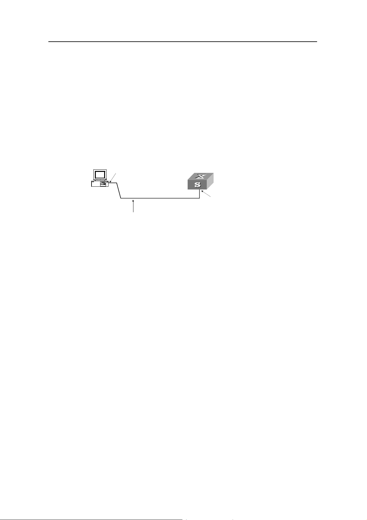
3Com Switch 8800 Configuration Guide Chapter 2 Logging into Switch
Chapter 2 Logging into Switch
2.1 Setting Up Configuration Environment Through the Console Port
Step 1: As shown in the figure below, to set up the local configuration environment,
connect the serial port of a PC (or a terminal) to the Console port of the switch with the
Console cable.
RS-232 Serial port
Console port
Console cable
Figure 2-1 Set up the local configuration environment through the Console port
Step 2: Run termin al emulator (such as Terminal on Windows 3X or the Hyper Terminal
on Windows 9X) on the Computer. Set the terminal communication parameters as
follows: Set the baud rate to 9600, databit to 8, parity check to none, stopbit to 1, flow
control to none and select the terminal type as VT100.
Figure 2-2 Set up new connection
2-1
Page 30
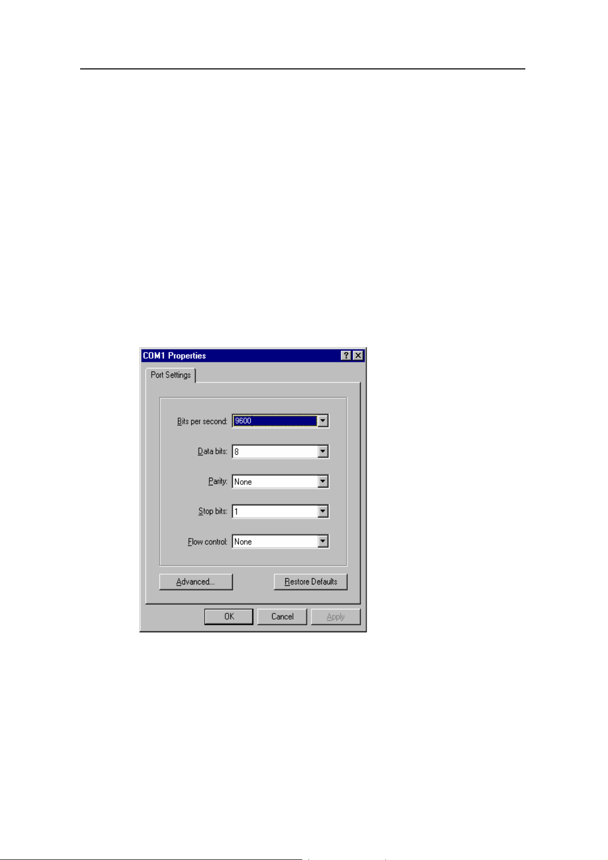
3Com Switch 8800 Configuration Guide Chapter 2 Logging into Switch
Figure 2-3 Configure the port for connection
Figure 2-4 Set communication parameters
Step 3: The switch i s powered on. Display self-test information of the switch and prompt
you to press Enter to show the command line prompt such as <SW8800>.
Step 4: Input a command to config ure the switch or view the operation st ate. Input a “?”
for an immediate help. For details of specific commands, refer to the following chapters.
2-2
Page 31

3Com Switch 8800 Configuration Guide Chapter 2 Logging into Switch
2.2 Setting Up Configuration Environment Through Telnet
2.2.1 Connecting a PC to the Switch Through Telnet
After you have correctly configured IP address of a VLAN interface for a switch via
Console port (using ip address command in VLAN interface view), and added the port
(that connects to a terminal) to this VLAN (usi ng port command in VLAN view), you can
telnet this switch and configure it.
Step 1: Before logging into the switch through telnet, you need to configure the Telnet
user name and password on the switch through the console port.
Note:
By default, the password is required for authenticating the Telnet user to log in the
switch. If a user logs in via the Telnet without password, he will see the prompt “Login
password has not been set !”.
<SW8800> system-view
Enter system view , return user view with Ctrl+Z.
[SW8800] user-interface vty 0
[SW8800-ui-vty0] set authentication password simple xxxx (xxxx is the preset login
password of Telnet user)
Step 2: To set up the configuration environment, connect the Ethernet port of the PC to
that of the switch via the LAN, as shown in
Workstation
Workstation
Ethernet port
Ethernet port
Ethernet
Ethernet
Server
Server
Workstation
Workstation
PC ( for co n fi g u ring th e sw i tch
PC ( for co n fi g u ring th e sw i tch
via Te l net )
via Te l net )
Figure 2-5.
Figure 2-5 Set up configuration environment through telnet
Step 3: Run Telnet on the PC and input the IP address of the VLAN connected to the PC
port, as shown in
Figure 2-6.
2-3
Page 32

3Com Switch 8800 Configuration Guide Chapter 2 Logging into Switch
Figure 2-6 Run Telnet
Step 4: The terminal displays “Login authentication!” and prompts the user to input the
logon password. After you input the correct password, it displays the command line
prompt (such as <SW8800>). If the prompt “All user interfaces are used, please try
later! The connection was closed by the remote host!” appears, it indicates that the
maximum number of Telnet users that can be accessed to the switch is reached at this
moment. In this case, please reconnect later. At most 5 Telnet users are allowed to log
on to the Switch 8800 simultaneously.
Step 5: Use the corresponding commands to configure the switch or to monitor the
running state. Enter “?” to get the immediate help. For details of specific commands,
refer to the following chapters.
Note:
z When configuring the switch via Telnet, do not modify the IP address of it unless
necessary, for the modification might cut the Telnet connection.
z By default, when a Telnet user passes the password authentication to log on to the
switch, he can access the commands at Level 0.
2.2.2 Telneting a Switch Through Another Switch
After a user has logged into a switch, he or she can configure another switch through
the switch via Telnet. The local switch serves as Telnet client and the peer switch
serves as Telnet server. If the ports connecting these two switches are in a same local
network, their IP addresses must be configured in the same network segment.
Otherwise, the two switches must establish a route that can reach each other.
As shown in the figure below, af ter you telnet to a switch, you can run telnet command
to log in and configure another switch.
2-4
Page 33

3Com Switch 8800 Configuration Guide Chapter 2 Logging into Switch
PC
Telnet Client
Telnet Server
Figure 2-7 Provide Telnet Client service
Step 1: Configure the Telnet user name and password on the Telnet Server through the
console port.
Note:
By default, the password is required for authenticating the Telnet user to log in the
switch. If a user logs in via the Telnet without password, he will see the prompt “Login
password has not been set !.”.
<SW8800> system-view
System View: return to User View with Ctrl+Z
[SW8800] user-interface vty 0
[SW8800-ui-vty0] set authentication password simple xxxx (xxxx is the preset login
password of Telnet user)
Step 2: The user logs in the Telnet Client (switch). For the login process, refer to the
section describing “Connecting a PC to the Switch through Telnet”.
Step 3: Perform the following operations on the Telnet Client:
<SW8800> telnet xxxx (xxxx can be the hostname or IP address of the Telnet Server. If it is the
hostname, you need to use the ip host command to specify.)
Step 4: Enter the preset login password and you will see the prompt such <S W8800>. If
the prompt “All user interfaces are used, please try later! The connection was clo sed by
the remote host!” appears, it indicates that the maximum number of Telnet users that
can be accessed to the switch is reached at this moment. In this case, please connect
later.
Step 5: Use the corresponding commands to configure the switch or view it running
state. Enter “?” to get the immediate help. For details of specific commands, refe r to the
following chapters.
2.3 Setting Up Configuration Environment Through a Dial-up the Modem
Step 1: Authenticate the Modem user via the Console port of the switch before he logs
in the switch through a dial-up Modem.
2-5
Page 34

3Com Switch 8800 Configuration Guide Chapter 2 Logging into Switch
Note:
By default, the password is required for authenticating the Modem user to log in the
switch. If a user logs in via the Modem without password, he will see the prompt “Login
password has not been set !.”.
<SW8800> system-view
System View: return to User View with Ctrl+Z..
[SW8800] user-interface aux 0
[SW8800-ui-aux0] set authentication password simple xxxx (xxxx is the preset login
password of the Modem user.)
Step 2: As shown in the figure below, to set up the remote configuration environment,
connect the Modems to a PC (or a terminal) serial port and the switch AUX port
respectively.
Modem serial port line
Telephone line
AUX port
Remote tel:
82882285
Modem
PSTN
Modem
Figure 2-8 Set up remote configuration environment
Step 3: Dial for connection to the switch, using the terminal emulat or and Modem on the
remote end. The number dialed shall be the telephone number of the Modem
connected to the switch. See the two figures below.
2-6
Page 35

3Com Switch 8800 Configuration Guide Chapter 2 Logging into Switch
Figure 2-9 Set the dialed number
Figure 2-10 Dial on the remote PC
Step 4: Enter the preset login password on the remote terminal emulator and wait for
the prompt such as <SW8800>. Then you can configure and man age the switch. Enter
“?” to get the immediate help. For details of specific commands, refer to the following
chapters.
Note:
By default, when a Modem user logs in, he can access the commands at Level 0.
2-7
Page 36

3Com Switch 8800 Configuration Guide Chapter 3 Command Line Interface
Chapter 3 Command Line Interface
3.1 Command Line Interface
The Switch 8800 provides a series of configuration commands and command line
interfaces for configuring and managing the switch. The command line interface has
the following characteristics:
z Local configuration via the Console port and AUX port.
z Local or remote configuration via Telnet.
z Remote configuration through dialing with modem via the AUX port.
z Hierarchy command protection to avoid the unauthorized users accessing switch.
z Enter a “?” to get immediate online help.
z Provide network testing commands, such as Tracert and Ping, to fast troubleshoot
the network.
z Provide various detailed debugging information to help with network
troubleshooting.
z Log in and manage other switch directly, using the Telnet command.
z Provide FTP service for the users to upload and download files.
z Provide the function similar to Doskey to execute a history command.
z The command line interpreter searches for target not fully matching the keywords.
It is ok for you to key in the whole keyword or part of it, as long as it is unique and
not ambiguous.
3.2 Command Line View
The Switch 8800 provides hierarchy protection for the command lines to avoid
unauthorized user accessing illegally.
Commands are classified into four levels, namely visit level, monitoring level,
configuration level and management level. They are introduced as follows:
z Visit level: Commands of this level involve command of network diagnosis tool
(such as ping and tracert), command of switch between different language
environments of user interface (language-mode) and telnet command etc. The
operation of saving configuration file is not allowed on this level of commands.
z Monitoring level: Commands of this level, including the display command and the
debugging command, are used to system maintenance, service fault diagnosis,
etc. The operation of saving configuration file is not allowed on this level of
commands.
z Configuration level: Service configuration commands, including routing command
and commands on each network layer, are used to provide direct network service
to the user.
3-1
Page 37

3Com Switch 8800 Configuration Guide Chapter 3 Command Line Interface
z Management level: They are commands that influence basis operation of the
system and system support module, which plays a support role on service.
Commands of this level involve file system commands, FTP commands, TFTP
commands, XModem downloading commands, user management commands,
and level setting commands.
At the same time, login users are classified into four levels that correspond to the four
command levels respectively. After users of different levels log in, they can only use
commands at the levels that are equal to or lower than its own level.
In order to prevent unauthorized users from illegal intrusion, user will be identified whe n
switching from a lower level to a higher level with super [ level ] command. User ID
authentication is performed when users at lower level switch to use rs at higher level. In
other words, user password of the higher level is needed (Suppose the user has set the
super password [ level level ] { simple | cipher } password.) For the sake of
confidentiality, on the screen the user cannot see the password that he entered. Only
when correct password is input for three times, can the user switch to the higher level.
Otherwise, the original user level will remain unchanged.
Different command views are implemented according to different requirements. They
are related to one another. For example, after logging in the switch, you will enter user
view, in which you can only use some basic functions such as displaying the running
state and statistics information. In user view, key in system-view to enter system view,
in which you can key in different configuration commands and enter the corresponding
views.
The command line provides the following views:
z User view
z System view
z Port view
z VLAN view
z VLAN interface view
z Local-user view
z User interface view
z FTP Client view
z SFTP Client view
z MST region view
z PIM view
z MSDP view
z IPv4 multicast sub-address family view
z RIP view
z OSPF view
z OSPF area view
z BGP view
z IS-IS view
3-2
Page 38

3Com Switch 8800 Configuration Guide Chapter 3 Command Line Interface
z Route policy view
z Basic ACL view
z Advanced ACL view
z Layer-2 ACL view
z Conform-level view
z WRED index view
z RADIUS server group view
z ISP domain view
z MPLS view
z VPNv4 sub-address family view
z VPN-instance sub-address family view
z Remote-peer view
z VSI-LDP view
z VSI view
z TACACS+ view
z Port group view
z Lanswitch view
The following table describes the function features of different views and the ways to
enter or quit.
Table 3-1 Function feature of command view
Command
view
User view
System
view
Function Prompt
Show the basic
information
about operation
<SW8800
>
and statistics
Configure
system
[SW8800]
parameters
Command to
enter
Enter right after
connecting the
switch
Key in
system-view in
user view
Command to
exit
quit
disconnects
to the switch
quit or return
returns to
user view
3-3
Page 39

3Com Switch 8800 Configuration Guide Chapter 3 Command Line Interface
Command
view
Port view
VLAN view
Function Prompt
[SW8800Ethernet2/
1/1]
Ethernet port
view:
Configure
Ethernet port
[SW8800GigabitEth
ernet2/1/1
]
parameters
[SW880010-Gigabit
Ethernet2/
1/1]
Configure VLAN
parameters
[SW8800Vlan1]
Command to
enter
100M Ethernet port
view
Key in interface
ethernet 2/1/1 in
system view
GigabitEthernet
port view
Key in interface
gigabitethernet
2/1/1 in system
view
10G Ethernet port
view
Key in interface
10-gigabitetherne
t 2/1/1 in system
view
Key in vlan 1 in
system view
Command to
exit
quit returns to
system view
return returns
to user view
quit returns to
system view
return returns
to user view
VLAN
interface
view
Local-user
view
User
interface
view
FTP Client
view
SFTP
Client view
MST
region view
Configure IP
interface
parameters for a
VLAN or a VLAN
[SW8800Vlan-interf
ace1]
aggregation
Configure local
user parameters
Configure user
interface
parameters
[SW8800-l
user-user
1]
[SW8800ui0]
Configure FTP
Client
[ftp]
parameters
Configure SFTP
Client
parameters
Configure MST
region
parameters
sftp-client
>
[SW8800mst-region
]
Key in interface
vlan-interface 1 in
system view
Key in local-user
user1 in system
view
Key in
user-interface 0 in
system view
Key in ftp in user
view
Key in sftp
ip-address in
system view
Key in stp
region-configurati
on in system view
quit returns to
system view
return returns
to user view
quit returns to
system view
return returns
to user view
quit returns to
system view
return returns
to user view
quit returns to
system view
quit returns to
system view
return returns
to user view
quit returns to
system view
return returns
to user view
3-4
Page 40

3Com Switch 8800 Configuration Guide Chapter 3 Command Line Interface
Command
view
PIM view
MSDP view
Configure PIM
parameters
Configure MSDP
parameters
Enter the IPv4
IPv4
multicast
sub-addres
s family
view
multicast
sub-address
family view to
configure MBGP
multicast
extension
parameters
RIP view
Configure RIP
parameters
Function Prompt
[SW8800PIM]
[SW8800msdp]
[SW8800bgp-af-mu
l]
[SW8800rip]
Command to
enter
Key in pim in
system view
Key in msdp in
system view
Key in ipv4-family
multicast in BGP
view
Key in rip in
system view
Command to
exit
quit returns to
system view
return returns
to user view
quit returns to
system view
return returns
to user view
quit returns to
BGP view
return returns
to user view
quit returns to
system view
return returns
to user view
OSPF view
OSPF area
view
BGP view
IS-IS view
Route
policy view
Configure OSPF
parameters
Configure OSPF
area parameters
Configure BGP
parameters
Configure IS-IS
parameters
Configure route
policy
parameters
[SW8800ospf]
[SW8800ospf-0.0.0.
1]
[SW8800bgp]
[SW8800-i
sis]
[SW8800route-polic
y]
quit returns to
Key in ospf in
system view
system view
return returns
to user view
quit returns to
Key in area 1 in
OSPF view
OSPF view
return returns
to user view
quit returns to
Key in bgp 100 in
system view
system view
return returns
to user view
quit returns to
Key in isis in
system view
system view
return returns
to user view
Key in
route-policy
policy1 permit
node 10 in system
view
quit returns to
system view
return returns
to user view
Basic ACL
view
Define the rule of
basic ACL
[SW8800aclbasic-200
0]
3-5
Key in acl number
2000 in system
view
quit returns to
system view
return returns
to user view
Page 41

3Com Switch 8800 Configuration Guide Chapter 3 Command Line Interface
Command
view
Advanced
ACL view
Layer-2
ACL view
Conform-le
vel view
Function Prompt
Define the rule of
advanced ACL
Define the rule of
layer-2 ACL
[SW8800acl-adv-30
00]
[SW8800acl-link-40
00]
Configure the
"DSCP +
Conform-level
Service group"
mapping table
and”EXP +
Conform-level>service
parameters”map
[SW8800conform-le
vel-0]
ping table and
"Local-preceden
ce +
Conform-level
802.1p priority"
mapping table
Command to
enter
Key in acl number
3000 in system
view
Key in acl number
4000 in system
view
Key in qos
conform-level 0 in
system view
Command to
exit
quit returns to
system view
return returns
to user view
quit returns to
system view
return returns
to user view
quit returns to
system view
return returns
to user view
WRED
index view
RADIUS
server
group view
ISP
domain
view
MPLS view
VPNv4
subaddres
s family
view
Configure
WRED
parameters
Configure radius
parameters
Configure ISP
domain
parameters
Configure MPLS
parameters
Configure
VPNv4 address
family
parameters
[SW8800-
wred-0]
[SW8800-
radius-1]
[SW8800-i
sp-3Com1
63.net]
[SW8800-
mpls]
[SW8800-
bgp-af-vp
n]
Key in wred 0 in
system view
Key in radius
scheme 1 in
system view
Key in domain
3Com163.net in
system view
Key in mpls in
system view
Key in ipv4-family
vpnv4 in BGP view
quit returns to
system view
return returns
to user view
quit returns to
system view
return returns
to user view
quit returns to
system view
return returns
to user view
quit returns to
system view
return returns
to user view
quit returns to
system view
return returns
to user view
3-6
Page 42

3Com Switch 8800 Configuration Guide Chapter 3 Command Line Interface
Command
view
VPN-instan
ce
subaddres
s family
view
Remote-pe
er view
VSI-LDP
view
VSI view
TACACS+
view
Configure VPN
instance
subaddress
family
parameters
Configure MPLS
peer group
parameters
Configure some
VPLS features
Specify VPLS
mode
Configure
TACACS+
protocol
parameters
Function Prompt
[SW8800-
bgp-af-vp
n-instance
]
[SW8800-
mpls-remo
te1]
[SW8800-
vsi-3Com-
ldp]
[SW8800-
vsi-3Com]
[SW8800-t
acacs+-3
Com]
Command to
enter
Key in ipv4-family
vpn-instance vpna
in BGP/RIP view
Key in mpls
remote1
Key in vsi 3Co m in
system view
Key in pwsignal
ldp in vsi view
Key in vsi 3Co m in
system view
Key in tacacs+
scheme 3Com in
system view
quit returns to
system view
return returns
to user view
quit returns to
system view
return returns
to user view
quit returns to
vsi view
return returns
to user view
quit returns to
system view
return returns
to user view
quit returns to
system view
return returns
to user view
Command to
exit
Combine the
ports with the
Port group
view
Lanswitch
view
same
configuration,
omitting
repeated
configuration
procedure
Enter lanswitch
view.
After entering
the specified
lanswitch view,
you can use the
specified
Ethernet switch.
[SW8800-
port-group
X]
[SW8800-l
answitchX
/X/X-/]
Key in port-group
X in system view
Key in lanswitch
X/X/X-/ in HGMP
view
3.3 Features and Functions of Command Line
3.3.1 Online Help of Command Line
quit returns to
system view
return returns
to user view
quit returns to
HGMP view
return returns
to user view
The command line interface provides the following online help modes.
z Full help
3-7
Page 43

3Com Switch 8800 Configuration Guide Chapter 3 Command Line Interface
z Partial help
You can get the help information through these online help commands, which are
described as follows.
1) Input “?” in any view to get all the commands in it and corresponding de scriptions.
<SW8800> ?
User view commands:
language-mode Specify the language environment
ping Ping function
quit Exit from current command view
super Privilege current user a specified priority level
telnet Establish one TELNET connection
tracert Trace route function
2) Input a command with a “?” separated by a space. If this position is for keywords,
all the keywords and the corresponding brief descriptions will be listed.
<SW8800> language-mode ?
chinese Chinese environment
english English environment
3) Input a command with a “?” separated by a space. If this position is for parameters,
all the parameters and their brief descriptions will be listed.
[SW8800] garp timer leaveall ?
INTEGER<65-32765> Value of timer in centiseconds
(LeaveAllTime > (LeaveTime [On all ports]))
Time must be multiple of 5 centiseconds
[SW8800] garp timer leaveall 300 ?
<cr>
<cr> indicates no parameter in this position. The next command line repeats the
command, you can press <Enter> to execute it directly.
4) Input a character string with a “?”, then all the commands with this cha racter string
as their initials will be listed.
<SW8800> p?
ping pwd
5) Input a command with a character string and “?”, then all the key words with this
character string as their initials in the command will be listed.
<SW8800> display ver?
version
6) Input the first letters of a keyword of a command and press <Tab> key. If no other
keywords are headed by this letters, then this unique keyword will be displayed
automatically.
7) To switch to the Chinese display for the above information, perform the
language-mode command.
3-8
Page 44

3Com Switch 8800 Configuration Guide Chapter 3 Command Line Interface
3.3.2 Displaying Characteristics of Command Line
Command line interface provides the following display characteristics:
z For users’ convenience, the instruction and help information can be displayed in
both English and Chinese.
z For the information to be displayed exceeding one screen, pausing function is
provided. In this case, users can have three choices, as shown in the table below.
Table 3-2 Functions of displaying
Key or Command Function
Press <Ctrl+C> when the display
pauses
Enter a space when the display pauses
Press <Enter> when the display pauses
3.3.3 History Command of Command Line
Command line interface provides the function similar to that of DosKey . The commands
entered by users can be automatically saved by the command line interface and you
can invoke and execute them at any time later. Histo ry command buf fer is defaulted a s
10. The operations are shown in the table below.
Table 3-3 Retrieve history command
Operation Key Result
Display history
command
display
history-command
Stop displaying and executing
command.
Continue to display the next screen of
information.
Continue to display the next line of
information.
Display history command by user
inputting
Retrieve the
previous history
command
Retrieve the next
history command
Up cursor key <↑> or
<Ctrl+P>
Down cursor key <↓>
or <Ctrl+N>
Retrieve the previous history
command, if there is any.
Retrieve the next history
command, if there is any.
Note:
Cursor keys can be used to retrieve the history commands in Windows 3.X Terminal
and Telnet. However, in Windows 9X HyperTerminal, the cursor keys ↑ and ↓ do not
work, because Windows 9X HyperTerminal defines the two keys differently. In this
case, use the combination keys <Ctrl+P> and <Ctrl+N> instead for the same purpose.
3-9
Page 45

3Com Switch 8800 Configuration Guide Chapter 3 Command Line Interface
3.3.4 Common Command Line Error Messages
All the input commands by users can be correctly executed, if they have passed the
grammar check. Otherwise, error messages will be reported to users. The common
error messages are listed in the following table.
Table 3-4 Common command line error messages
Error messages Causes
Cannot find the command.
Unrecognized command
Incomplete command The input command is incomplete.
Too many parameters Enter too many parameters.
Ambiguous command The parameters entered are not specific.
Cannot find the keyword.
Wrong parameter type.
The value of the parameter exceeds the range.
3.3.5 Editing Characteristics of Command Line
Command line interface provides the basic command editing function and supports to
edit multiple lines. A command cannot longer than 256 characte rs. See the table below .
Table 3-5 Editing functions
Key Function
Common keys
Backspace
Insert from the cursor position and the cursor moves to the
right, if the edition buffer still has free space.
Delete the character preceding the cursor and the cursor
moves backward.
Leftwards cursor key
<←> or <Ctrl+B>
Rightwards cursor key
<→> or <Ctrl+F>
Up cursor key <↑> or
<Ctrl+P>
Down cursor key <↓>
or <Ctrl+N>
Move the cursor a character backward
Move the cursor a character forward
Retrieve the history command.
3-10
Page 46

3Com Switch 8800 Configuration Guide Chapter 3 Command Line Interface
Press <Tab> after typing the incomplete key word and the
system will execute the partial help: If the key word
matching the typed one is unique, the system will replace
<Tab>
the typed one with the complete key word and display it in
a new line; if there is not a matched key word or the
matched key word is not unique, the system will do no
modification but display the originally typed word in a new
line.
3-11
Page 47

3Com Switch 8800 Configuration Guide Chapter 4 User Interface Configuration
Chapter 4 User Interface Configuration
4.1 User Interface Overview
User interface configuration is another way provided by the switch to configure and
manage the port data.
The Switch 8800 supports the following configuration methods:
z Local configuration via the Console port and AUX port
z Local and remote configuration through Telnet on Ethernet port
z Remote configuration through dialing with modem via the AUX port.
According to the above-mentioned configuration methods, there are three types of user
interfaces:
z Console user interface
Console user interface is used to log in the switch via the Console port. A switch can
only have one Console user interface.
z AUX user interface
AUX user interface is used to log in the switch locally or remotely with a modem via the
AUX port. A switch can only have one AUX user interface. The local config uration for it
is similar to that for the Console user interface.
z VTY user interface
VTY user interface is used to telnet the switch. A switch can have up to five VTY user
interface.
User interface is numbered in the following two ways: absolute number and relative
number.
I. Absolute number
The user interfaces for IP PBX fall into three types and they are sequenced as follows:
console interface (CON), auxiliary interface (AUX) and virtual interface (VTY). A switch
has one CON, one AUX and multiple VTYs. The first absol ute number is designat ed as
0; the second one is designated as 1; and so on. This method can specify a unique user
interface or a group of interfaces.
It follows the rules below.
z Console user interface is numbered as the first interface designated as user
interface 0.
z AUX user interface is numbered as the second interface designated as user
interface 1.
4-1
Page 48

3Com Switch 8800 Configuration Guide Chapter 4 User Interface Configuration
z VTY is numbered after AUX user interface. The absolute number of the first VTY is
incremented by 1 than the AUX user interface number.
II. Relative number
The relative number is in the format of “user interface type” + “number”. The “number”
refers to the internal number for each user interface type. This method can only specify
one interface or one group of interfaces for a user interface type instead of different
user interface types.
It follows the rules below:
z Number of Console user interface: console 0.
z Number of AUX user interface: AUX 0.
z Number of VTY: The first VTY interface is designated as VTY 0; the second one is
designated as VTY 1, and so on.
4.2 User Interface Configuration
The following sections describe the user interface configuration tasks.
z Entering User Interface View
z Define the Login Header
z Configuring Asynchronous Port Attributes
z Configuring Terminal Attributes
z Managing Users
z Configuring Modem Attributes
z Configuring Redirection
4.2.1 Entering User Interface View
The following command is used for entering a user interface view. You can enter a
single user interface view or multi user interface view to configure one or more user
interfaces respectively.
Perform the following configuration in system view.
Table 4-1 Enter user interface view
Operation Command
Enter a single user interface view or
multi user interface views
user-interface [ type ] first-number
[ last-number ]
4.2.2 Define the Login Header
The following command is used for configuring the displayed header when user login.
4-2
Page 49

3Com Switch 8800 Configuration Guide Chapter 4 User Interface Configuration
When the users log in the switch, if a connection is activated, the login header will be
displayed. After the user successfully logs in the switch, the shell header will be
displayed.
Perform the following configuration in system view.
Table 4-2 Configure the login header.
Operation Command
Configure the login header header [ shell | incoming | login ] text
Remove the login header configured undo header [ shell | incoming | login ]
Note that if you press <Enter> after typing any of the three keywords shell, login and
incoming in the command, then what you type after the word header is th e contents of
the login information, instead of identifying header type.
4.2.3 Configuring Asynchronous Port Attributes
The following commands can be used for configuring the attributes of the
asynchronous port in asynchronous interactive mode, including speed, flow control,
parity, stop bit and data bit.
Perform the following configurations in user interface (Console and AUX use r interface
only) view.
I. Configuring the transmission speed
Table 4-3 Configure the transmission speed
Operation Command
Configure the transmission speed
Restore the default transmission speed
speed speed-value
undo speed
By default, the transmission speed on an asynchronous port is 9600bps.
II. Configuring flow control
Table 4-4 Configure flow control
Operation Command
Configure the flow control
Restore the default flow control mode
flow-control { hardware | none |
software }
undo flow-control
4-3
Page 50

3Com Switch 8800 Configuration Guide Chapter 4 User Interface Configuration
By default, the flow control on an asynchronous port is none, that is, no flow control will
be performed.
III. Configuring parity
Table 4-5 Configure parity
Operation Command
Configure parity mode parity { even | mark | none | odd | space }
Restore the default parity mode
By default, the parity on an asynchronous port is none, that is, no parity bit.
undo parity
IV. Configuring the stop bit
Table 4-6 Configure the stop bit
Operation Command
Configure the stop bit stopbits { 1 | 1.5 | 2 }
Restore the default stop bit
By default, an asynchronous port supports 1 stop bit.
Note that setting 1.5 stop bits is not available on the Switch 8800.
undo stopbits
V. Configuring the data bit
Table 4-7 Configure the data bit
Operation Command
Configure the data bit databits { 7 | 8 }
Restore the default data bit
By default, an asynchronous port supports 8 data bit s.
4.2.4 Configuring Terminal Attributes
The following commands can be used for configuring the terminal attributes, including
enabling/disabling terminal service, disconnection upon timeout, lockable user
interface, configuring terminal screen length and history comman d buffer size.
Perform the following configuration in user interface view. Perform lock command in
user view.
I. Enabling/disabling terminal service
undo databits
4-4
Page 51

3Com Switch 8800 Configuration Guide Chapter 4 User Interface Configuration
After the terminal service is disabled on a user interface, you cannot log in to the switch
through the user interface. However, the user logged in through the user interface
before disabling the terminal service can continue his operation. After such user logs
out, he cannot log in again. In this case, a user can log in to the switch through the user
interface only when the terminal service is enabled again.
Table 4-8 Enable/disable terminal service
Operation Command
Enable terminal service
Disable terminal service
shell
undo shell
By default, terminal service is enabled on all the user interfaces.
Note the following points:
z For the sake of security, the undo shell command can only be used on the user
interfaces other than Console user interface.
z You cannot use this command on the user interface via which you log in.
z You will be asked to confirm before using undo shell on any legal user interface.
II. Configuring idle-timeout
Table 4-9 Configure idle-timeout
Operation Command
Configure idle-timeout idle-timeout minutes [ seconds ]
Restore the default idle-timeout
undo idle-timeout
By default, idle-timeout is enabled and set to 10 minutes on all the user interfaces. That
is, the user interface will be disconnected automatically after 10 minutes without any
operation.
idle-timeout 0 means disabling idle-timeout.
III. Locking user interface
This configuration is to lock the current user interface and prompt the user to enter the
password. This makes it impossible for others to operate in the interface after the user
leaves.
Table 4-10 Lock user interface
Operation Command
Lock user interface
lock
4-5
Page 52

3Com Switch 8800 Configuration Guide Chapter 4 User Interface Configuration
IV. Setting the screen length
If a command displays more than one screen of information, you can use the following
command to set how many lines to be displayed in a screen, so that the information can
be separated in different screens and you can vie w it more conveniently.
Table 4-11 Set the screen length
Operation Command
Set the screen length
Restore the default screen length
By default, the terminal screen length is 24 lines.
screen-length 0 indicates to disable screen display separation function.
V. Setting the history command buffer size
Table 4-12 Set the history command buffer size
Set the history command buffer size
Restore the default history command
buffer size
By default, the size of the history command buffer is 10, that is, 10 history commands
can be saved.
4.2.5 Managing Users
screen-length screen-length
undo screen-length
Operation Command
history-command max-size value
undo history-command max-size
The management of users includes the setting of user logon authentication method,
level of command which a user can use after logging on, level of command which a
user can use after logging on from the specifically user interface, and command level.
I. Configuring the authentication method
The following command is used for configuring the user login authentication m ethod to
deny the access of an unauthorized user .
Perform the following configuration in user interface view.
Table 4-13 Configure the authentication method
Operation Command
Configure the authentication method
4-6
authentication-mode { password |
scheme | none }
Page 53

3Com Switch 8800 Configuration Guide Chapter 4 User Interface Configuration
By default, terminal authentication is not required for local users log in via the Console
port. However, password authentication is required for local users and remote Modem
users log in via the AUX po rt, and Telnet users log in through Ethernet port.
1) Perform local password authentication to the user interface
Using authentication-mode password command, you can perform local password
authentication. That is, you need use the command below to configure a login
password in order to login successfully.
Perform the following configuration in user interface view.
Table 4-14 Configure the local authentication password
Operation Command
Configure the local authentication
password
Remove the local authentication
password
set authentication password { cipher |
simple }password
undo set authentication password
Configure for password authentication when a user logs in through a VTY 0 user
interface and set the password to 3Com.
[SW8800] user-interface vty 0
[SW8800-ui-vty0] authentication-mode password
[SW8800-ui-vty0] set authentication password simple 3Com
2) Perform local or remote authentication of username and password to the user
interface
Using authentication-mode scheme command, you can perform local or remote
authentication of username and password. The type of the authentication depends on
your configuration. For detailed information, see “Security” section.
In the following example, local username and password authentication are configured.
Perform username and password authentication when a user logs in through VTY 0
user interface and set the username and password to zb r and 3Com respectively.
[SW8800-ui-vty0] authentication-mode scheme
[SW8800-ui-vty0] quit
[SW8800] local-user zbr
[SW8800-luser-zbr] password simple 3Com
[SW8800-luser-zbr] service-type telnet
3) No authentication
[SW8800-ui-vty0] authentication-mode none
4-7
Page 54

3Com Switch 8800 Configuration Guide Chapter 4 User Interface Configuration
Note:
By default, password is required to be set for authenticating local users and remote
Modem users log in via the AUX port, and Telnet users log in through Ethernet port. If
no password has been set, the following prompt will be displayed “Login password has
not been set !.”
If the authentication-mode none command is used, the local and Modem users via
the AUX port and Telnet users will not be required to input password.
II. Setting the command level used after a user logging in
The following command is used for setting the command level used after a user logging
in.
Perform the following configuration in local-user view.
Table 4-15 Set the command level used after a user logging in
Operation Command
Set command level used after a user
logging in
Restore the default command level used
after a user logging in
service-type telnet [ level level ]
undo service-type telnet [ level ]
By default, the specified logon user can access the commands at Level 0.
III. Setting the command level used after a user logs in from a user interface
You can use the following command to set the command level after a user log s in from
a specific user interface, so that a user is able to execute the commands at such
command level.
Perform the following configuration in user interface view.
Table 4-16 Set the command level used after a user logging in from a user interface
Operation Command
Set command level used after a user
logging in from a user interface
user privilege level level
Restore the default command level used
after a user logging in from a user
undo user privilege level
interface
By default, you can access the commands at Level 3 after logging in through the
Console user interface, and the commands at Level 0 after lo gging in through t he AUX
or VTY user interface.
4-8
Page 55

3Com Switch 8800 Configuration Guide Chapter 4 User Interface Configuration
Note:
When a user logs in the switch, the command level that it can access depends on two
points. One is the command level that the user itself can access, the other is the set
command level of this user interface. If the two levels are different, the former will be
taken. For example, the command level of VTY 0 user interface is 1, however, you have
the right to access commands of level 3; if you log in from VTY 0 user interface, you can
access commands of level 3 and lower.
IV. Setting the command priority
The following command is used for setting the priority of a specified command in a
certain view. The command levels include visit, monitoring, configuration, and
management, which are identified with 0 through 3 respectively. An administrator
assigns authorities as per user requirements.
Perform the following configuration in system view.
Table 4-17 Set the command priority
Operation Command
Set the command priority in a specified
view.
Restore the default command level in a
specified view.
command-privilege level level view
view command
Undo command-privilege view view
command
V. Setting input protocol for a user terminal
You can use the following command to set input protocol for a user terminal. The input
protocol type can be TELNET, SSH or all.
Perform the following configuration in user interface view.
Table 4-18 Set input protocol for a user terminal
Operation Command
Set input protocol for a user terminal protocol inbound { all | telnet | ssh }
By default, the input protocol type for a user terminal is all.
4-9
Page 56

3Com Switch 8800 Configuration Guide Chapter 4 User Interface Configuration
4.2.6 Configuring Modem Attributes
When logging in the switch via the Modem, you can use the following commands to
configure these parameters.
Perform the following configuration in AUX user interface view.
Table 4-19 Configure Modem attributes
Operation Command
Set the interval since the system receives
the RING until CD_UP
Restore the default interval since the
system receives the RING until CD_UP
Configure auto answer
Configure manual answer
Configure to allow call-in
Configure to bar call-in
Configure to permit call-in and call-out.
Configure to disable call-in and call-out
4.2.7 Configuring Redirection
I. Send command
The following command can be used for sending messages between user interfaces.
Perform the following configuration in user view.
modem timer answer seconds
undo modem timer answer
modem auto-answer
undo modem auto-answer
modem call-in
undo modem call-in
modem both
undo modem both
Table 4-20 Configure to send messages between different user interfaces.
Operation Command
Configure to send messages between
different user interfaces.
send { all | number | type number }
II. Auto-execute command
The following command is used to automatically run a command after you log in. Af ter a
command is configured to be run automatically, it will be automatically executed when
you log in again.
This command is usually used to automatically execute telnet command on the
terminal, which will connect the user to a designated device automatically.
Perform the following configuration in user interface view.
4-10
Page 57

3Com Switch 8800 Configuration Guide Chapter 4 User Interface Configuration
Table 4-21 Configure to automatically run the command
Operation Command
Configure to automatically run the command
Configure not to automatically run the
command
auto-execute command text
undo auto-execute command
Note the following points:
z After executing this command, the user interface can no longer be used to carry
out the routine configurations for the local system. Use this command with cautio n.
z Make sure that you will be able to log in the system in some other way and cancel
the configuration, before you use the auto-execute command command and
save the configuration.
Telnet 10.110.100.1 after the user logs in through VT Y0 automatically.
[SW8800-ui-vty0] auto-execute command telnet 10.110.100.1
When a user logs on via VTY 0, the system will run telnet 10.110.100.1 automatically.
4.3 Displaying and Debugging User Interface
After the above configuration, execute display command in any view to display the
running of the user interface configuration, and to verify the effect of the configuration.
Execute free command in user view to clear a specified user interface.
Table 4-22 Display and debug user interface
Operation Command
Clear a specified user interface free user-interface [ type ] number
Display the user application information
of the user interface
Display the physical attributes and some
configurations of the user interface
display users [ all ]
display user-interface [ type number |
number ] [ summary ]
4-11
Page 58

3Com Switch 8800 Configuration Guide Chapter 5 Management Interface Configuration
Chapter 5 Management Interface Configuration
5.1 Management Interface Overview
The Switch 8800 provides a 10/100Base-TX management interface on the Fabric. The
management interface can connect a background PC for softwa re loading and system
debugging, or a remote network management station for remote system manage ment.
5.2 Management Interface Configuration
The following sections describe management interface configuration t asks.
z Configuring interface IP address
z Enabling/disabling the interface
z Setting interface description
z Displaying current system information
z Test network connectivity (ping, tracert)
See the Port and System Management parts of this manual for details.
Caution:
Only the management interface configured with an IP address can run normally.
5-1
Page 59

3Com Switch 8800 Configuration Guide Chapter 6 Ethernet Port Configuration
Chapter 6 Ethernet Port Configuration
6.1 Ethernet Port Overview
The Switch 8800 provides conventional Ethernet ports, fast Ethernet port s, 1000 Mbp s
Ethernet ports and 10 Gbps Ethernet ports. The configurations of these Ethernet ports
are basically the same, which will be described in the following sections.
6.2 Ethernet Port Configuration
The following sections describe Ethernet port configuration tasks:
z Entering Ethernet Port View
z Enabling/Disabling an Ethernet Port
z Setting Ethernet Port Description
z Setting the Duplex Attribute of the Ethernet Port
z Setting Speed on the Ethernet Port
z Setting the Cable Type for the Ethernet Port
z Enabling/Disabling Flow Control for the Ethernet Port
z Permitting/Forbidding Jumbo Frame to Pass the Ethernet Port
z Setting the Ethernet Port Broadcast Suppression Ratio
z Setting the Ethernet Port Mode
z Setting the Link Type for the Ethernet Port
z Adding the Ethernet Port to Specified VLANs
z Setting the Default VLAN ID for the Ethernet Port
z Setting the VLAN VPN Feature
z Copying Port Configuration to Other Ports
z Setting Port Hold Time
z Setting the Ethernet Port in Loopback Mode
6.2.1 Entering Ethernet Port View
Before configuring the Ethernet port, enter Ethernet port view first.
Perform the following configuration in system view.
Table 6-1 Enter Ethernet port view
Operation Command
Enter Ethernet port view
interface { interface_type interface_num |
interface_name }
6-1
Page 60

3Com Switch 8800 Configuration Guide Chapter 6 Ethernet Port Configuration
6.2.2 Enabling/Disabling an Ethernet Port
After configuring the related parameters and protocol of the port, you can use undo
shutdown command to enable the port. If you do not want a port to forward data any
more, use shutdown command to disable it.
Perform the following configuration in Ethernet port view.
Table 6-2 Enable/disable an Ethernet port
Operation Command
Disable an Ethernet port
Enable an Ethernet port
By default, the port is enabled.
6.2.3 Setting Ethernet Port Description
To distinguish the Ethernet ports, you can use the following command to make some
necessary descriptions.
Perform the following configuration in Ethernet port group view.
Table 6-3 Set Ethernet port description
Operation Command
Set an Ethernet port description
Delete the Ethernet port description
By default, an Ethernet port has no description.
shutdown
undo shutdown
description text
undo description
6.2.4 Setting the Duplex Attribute of the Ethernet Port
To configure a port to send and receive data packets at the same time, set it to
full-duplex. To configure a port to either send or receive data packets at a time, set it to
half-duplex. If the port has been set to auto-negotiation mode, the local and peer ports
will automatically negotiate about the duplex mode.
Perform the following configuration in Ethernet port view.
Table 6-4 Set the duplex attribute for the Ethernet port
Operation Command
Set duplex attribute for Ethernet port duplex { auto | full | half }
Restore the default duplex attribute of Ethernet port
6-2
undo duplex
Page 61

3Com Switch 8800 Configuration Guide Chapter 6 Ethernet Port Configuration
Note that, 10/100 Mbps electrical Ethernet port can operate in full-duplex, half-duplex
or auto-negotiation mode. The10/100/1000 Mbps electrical Ethernet port can operate
in full duplex, half duplex or auto-negotiation mode. When the port operates at 1000
Mbps or in auto mode, the duplex mode can be set to full (full duplex) or auto
(auto-negotiation). The optical 100/1000 Mbps and 10 Gbps Ethernet ports work in full
duplex mode without user intervention.
The port defaults the auto (auto-negotiation) mode.
6.2.5 Setting Speed on the Ethernet Port
You can use the following command to set the speed on the Ethernet port. If the speed
is set to auto-negotiation mode, the local and peer ports will automatically negotiate
about the port speed.
Perform the following configuration in Ethernet port view.
Table 6-5 Set speed on the Ethernet port
Operation Command
Set Ethernet port speed speed { 10 | 100 | 1000 | 10000 | auto }
Restore the default speed on Ethernet
port
Note that, the 10/100 Mbps electrical Ethernet port can operate at 10 Mbps, 100 Mbps
and in auto mode. You can set it accordingly. The 10/100/1000Mbps electrical Ethernet
port can operate at 10 Mbps, 100 Mbps, or 1000 Mbps as per different requirements.
However in half duplex mode, the port cannot operate at 1000 Mbps or in auto mode.
The 100 Mbps optical Ethernet port supports 100 Mbps; the 1000 Mbps optical
Ethernet port supports 1000 Mbps; the 10 Gbps opti cal Ethernet port support s 10 Gbps
without user intervention.
By default, the speed of the port is in auto mode.
undo speed
6.2.6 Setting the Cable Type for the Ethernet Port
The Ethernet port supports the straight-through and cross-over network cables. The
following command can be used for configuring the cable type.
Perform the following configuration in Ethernet port view.
Table 6-6 Set the type of the cable connected to the Ethernet port
Operation Command
Set the type of the cable connected to
the Ethernet port
6-3
mdi { across | auto | normal }
Page 62

3Com Switch 8800 Configuration Guide Chapter 6 Ethernet Port Configuration
Operation Command
Restore the default type of the cable
connected to the Ethernet port
Note that, the settings only take effect on 10/100 Mbps and 10/100/1000 Mbps
electrical ports.
By default, the cable type is auto (auto-recognized). That is, the system can
automatically recognize the type of cable connecting to the port.
undo mdi
6.2.7 Enabling/Disabling Flow Control for the Ethernet Port
After enabling flow control in both the local and the peer switch, if conge stion occurs in
the local switch, the switch will inform its peer to pause packet sending. Once the peer
switch receives this message, it will pause p acket sending, and vice versa. In this way,
packet loss is reduced effectively. The flow control function of the Ethernet port can be
enabled or disabled through the following command.
Perform the following configuration in Ethernet port view.
Table 6-7 Enable/disable flow control for the Ethernet port
Operation Command
Enable Ethernet port flow control
Disable Ethernet port flow control
By default, Ethernet port flow control is disabled.
flow-control
undo flow-control
6.2.8 Permitting/Forbidding Jumbo Frame to Pass the Ethernet Port
The Ethernet port may encounter the jumbo frame exceeding the standard frame
length, when switching large throughput data like transmitting files. This comman d can
forbid or permit the jumbo frame to pass the Ethernet port.
Perform the following configuration in Ethernet port view.
Table 6-8 Permit/forbid jumbo frame to pass the Ethernet port
Operation Command
Permit jumbo frame to pass the Ethernet port
Forbid jumbo frame to pass the Ethernet port
jumboframe enable
[ jumboframe-value ]
undo jumboframe enable
By default, the jumbo frame is permitted to pass the Ethernet port.
6-4
Page 63

3Com Switch 8800 Configuration Guide Chapter 6 Ethernet Port Configuration
Note that, the values can be consecutive, but the effective values are discrete. The
effective frame length for the FE port is 1552. The effe ctive frame length for the GE port
and 10 GE port is 1552, 9022, 9192 and 10240. You can execute the display interface
command to view the configured effective value for the port.
6.2.9 Setting the Ethernet Port Broadcast Suppression Ratio
You can use the following commands to restrict the broadcast traffic. Once the
broadcast traffic exceeds the value set by the user, the system will maintain an
appropriate broadcast packet ratio by discarding the overflow traffic, so as to suppress
broadcast storm, avoid suggestion and ensure the normal service. The parameter is
taken the maximum wire speed ratio of the broadcast traffic allowed on the port. The
smaller the ratio is, the smaller the broadcast traffic is allowed. If the ratio is 100%, it
means not to perform broadcast storm suppression on the port.
Perform the following configuration in Ethernet port view.
Table 6-9 Set the Ethernet port broadcast suppression ratio
Operation Command
Set Ethernet port broadcast suppression ratio
Restore the default Ethernet port broadcast
suppression ratio
By default, 50% broadcast traffic is allowed to pass,
6.2.10 Setting the Ethernet Port Mode
Most ports adopt the LAN mode for general data exchange. The port must wo rk in WAN
mode, however, if it needs special frame format for data transfer (such as in fiber
transmission). You can configure network mode available on the port using the
port-mode command.
Perform the following configuration in Ethernet port view.
Table 6-10 Set the Ethernet port mode
Operation Command
Set the Ethernet port mode port-mode { wan | lan }
broadcast-suppression pct
undo broadcast-suppression
Restore the default Ethernet port mode
By default, the Ethernet port works in LAN mode.
Note that only GE or 10GE port supports this command.
6-5
undo port-mode
Page 64

3Com Switch 8800 Configuration Guide Chapter 6 Ethernet Port Configuration
6.2.11 Setting the Link Type for the Ethernet Port
Ethernet port can operate in three different link types, access, hybrid, and trunk types.
The access port carries one VLAN only, used for connecting to the user’s computer.
The trunk port can belong to more than one VLAN and receive/send the packets on
multiple VLANs, used for connection between the switches. The hybrid port can also
carry more than one VLAN and receive/send the packets on multiple VLANs, used for
connecting both the switches and user’s computers. The difference betwe en the hybrid
port and the trunk port is that the hybrid port allows the packet s from multiple VLANs to
be sent without tags, but the trunk port only allows the packet s from the default VLAN to
be sent without tags.
Perform the following configuration in Ethernet port view.
Table 6-11 Set the link type for the Ethernet port
Operation Command
Configure the port as access port
Configure the port as hybrid port
Configure the port as trunk port
Restore the default link type, that is, the
access port
Y ou can co nfigure three types of ports concurrently on the same swit ch, but you cannot
switch between trunk port and hybrid port. You must turn it first into access port and
then set it as other type. For example, you cannot configure a trunk port directly as
hybrid port, but first set it as access port and then as hybrid port.
By default, the port is access port.
port link-type access
port link-type hybrid
port link-type trunk
undo port link-type
6.2.12 Adding the Ethernet Port to Specified VLANs
The following commands are used for adding an Ethernet port to a specified VLAN. The
access port can only be added to one VLAN, while the hybrid and trunk ports can be
added to multiple VLANs.
Perform the following configuration in Ethernet port view.
Table 6-12 Add the Ethernet port to specified VLANs
Operation Command
Add the current access port to a
specified VLAN
Add the current hybrid port to specified
VLANs
6-6
port access vlan vlan_id
port hybrid vlan vlan_id_list { tagged |
untagged }
Page 65

3Com Switch 8800 Configuration Guide Chapter 6 Ethernet Port Configuration
Operation Command
Add the current trunk port to specified
VLANs
Remove the current access port from to
a specified VLAN
Remove the current hybrid port from to
specified VLANs
Remove the current trunk port from
specified VLANs
port trunk permit vlan { vlan_id_list |
all }
undo port access vlan
undo port hybrid vlan vlan_id_list
undo port trunk permit vlan
{ vlan_id_list | all }
Note that the access port shall be added to an existing VLAN other than VLAN 1. The
VLAN to which Hybrid port is added must have been existed.
After adding the Ethernet port to specified VLANs, the local port can forward packets of
these VLANs. The hybrid and trunk ports can be added to multiple VLANs, thereby
implementing the VLAN intercommunication between peers. For the hybrid port, you
can configure to tag some VLAN packets, based on which the packets can be
processed differently.
6.2.13 Setting the Default VLAN ID for the Ethernet Port
Since the access port can only be included in one VLAN only, its default VLAN is the
one to which it belongs. The hybrid port and the trunk port can be included in several
VLANs, it is necessary to configure the default VLAN ID. If the default VLAN ID has
been configured, the packets without VLAN Tag will be forwarded to the port that
belongs to the default VLAN. When sending the packets with VLAN Tag, if the VLAN ID
of the packet is identical to the default VLAN ID of the port, the system will remove
VLAN Tag before sending this packet.
Perform the following configuration in Ethernet port view.
Table 6-13 Set the default VLAN ID for the Ethernet port
Operation Command
Set the default VLAN ID for the hybrid port
Set the default VLAN ID for the trunk port
Restore the default VLAN ID of the hybrid
port to the default value
Restore the default VLAN ID of the trunk port
to the default value
port hybrid pvid vlan vlan_id
port trunk pvid vlan vlan_id
undo port hybrid pvid
undo port trunk pvid
Note that: to guarantee the proper packet transmission, the default VLAN ID of local
hybrid port or Trunk port should be id entical with that of the hybrid p ort or T runk p ort on
the peer switch.
6-7
Page 66

3Com Switch 8800 Configuration Guide Chapter 6 Ethernet Port Configuration
By default, the VLAN of hybrid port and trunk port is VLAN 1 and that of the access port
is the VLAN to which it belongs
6.2.14 Setting the VLAN VPN Feature
VLAN Tag consists of 12 bits (defined by IEEE802.1Q), so Ethernet Switches can
support up to 4k VLANs. In networking, especially in MAN (metropolitan area network),
a large numbers of VLANs are required to segment users. In this case, 4k VLANs are
not enough.
VLAN VPN feature can provide duplex VLAN T ags to a p acket, i.e. mark the packet with
another VLAN Tag besides the original one, thus to provide 4k x 4k VLANs to meet
user’s demands. At the same time, VLAN VPN feature provides the following functions:
using the original VLAN Tag to differentiate users and services, and using the new
VLAN Tag to load service and VPN users. These make VLAN configuration simple and
practicable. Thus, Ethernet Switches can meet the requirement of MAN.
If VLAN VPN is enabled on a port, all the packets (no matter wheth er it carries a VLAN
Tag or not) will be given a new Tag that specifies the default VLAN of this port.
Therefore, the packets that have had a VLAN Tag get two Tags, and the packets that
have not had a VLAN Tag get one.
Perform the following configuration in Ethernet port view.
Table 6-14 Set the VLAN VPN feature
Operation Command
Enable the VLAN VPN feature
Disable the VLAN VPN feature
Note that if anyone of GVRP, STP , and 802.1x has been enabled on a port, VLAN VPN
cannot be enabled on it.
By default, the port VLAN VPN is disabled.
vlan-vpn enable
undo vlan-vpn
6.2.15 Copying Port Configuration to Other Ports
To keep the configuration of other ports consistent with a specified port, you can use
copy configuration command to copy the configuration of that specified port to other
ports. Such configurations may involve: STP setting, QoS setting, LACP setting, and
port setting. The detailed table is as follows:
Table 6-15 Configurations that can be copied
Attribute Detailed Setting
Enable/disable STP STP setting
Port priority
6-8
Page 67

3Com Switch 8800 Configuration Guide Chapter 6 Ethernet Port Configuration
QoS setting
Path cost
Link attributes(point-to-point or not)
Port mCheck
Max transmission speed
Enable/disable root protection
Enable/disable loop protection
Edge or non-edge port
Reset ARP or not
Define/apply flow template
Traffic reshaping
Traffic redire ction
Packet filtering
Priority re-assignment
Traffi c st at isti cs
Traffic mirroring
Rate limiting
Permitted VLAN ID
Default VLAN ID
Add ports to VLAN
Port setting
Default 802.1p priority
Port speed, duplex mode
Port link type
LACP Enable/disable LACP on the port
Note:
z Using copy configuration command will clear protocol VLAN attributes of the
destination port, but it can not copy protocol VLAN attributes of source port to the
destination port.
z Using the copy configuration command, you can only copy the configurations of
Ethernet ports, GigabitEthernet ports and aggregation groups.
Perform the following configuration in system VLAN
6-9
Page 68

3Com Switch 8800 Configuration Guide Chapter 6 Ethernet Port Configuration
Table 6-16 Copy port configuration to other ports
Operation Command
Copy port
configuration to
other ports
Note that if the copy source is an aggregation group, take th e port with minimum Active
as the source; if the copy destination is an aggregation group, make the configurations
of all group member ports identical with that of the source. You cannot specify a
dynamic aggregation group as the copy destination.
copy configuration source { interface-type interface-number |
interface-name | aggregation-group agg-id } destination
{ interface_list [ aggregation-group agg-id ] |
aggregation-group agg-id }
6.2.16 Setting Port Hold Time
When you use the shutdown/undo shutdown command on ports too frequently, the
switch may fail. Therefore, you can configure port hold time to prohibit frequent change
of the port status.
Perform the following configuration in system view.
Table 6-17 Set the port hold time
Operation Command
Set the port hold time link-status hold hold-time
Restore the default value
By default, the port hold time is set to 3 seconds.
undo link-status hold
6.2.17 Setting the Ethernet Port in Loopback Mode
Perform the following configuration in Ethernet port view.
Table 6-18 Set the Ethernet port in loopback mode
Operation Command
Set the Ethernet port in loopback mode loopback { external | internal }
Remove loopback configuration on the port
By default, the Ethernet port is set in loopback mode. At present, the Switch 8800 does
not support external loopback mode.
undo loopback
6-10
Page 69

3Com Switch 8800 Configuration Guide Chapter 6 Ethernet Port Configuration
6.3 Displaying and Debugging Ethernet Port
After the above configuration, execute display command in any view to display the
running of the Ethernet port configuration, and to verify the effect of the configuration.
Execute reset command in user view to clear the statistics information of the port.
Table 6-19 Display and debug Ethernet port
Operation Command
display interface { interface_type |
Display all the information of the port
Display hybrid port or trunk port display port { hybrid | trunk }
interface_type interface_num [ packets ] |
interface_name }
Display the information of VLAN VPN
Display the statistics information of
the port
Clear the statistics information of the
port
display port vlan-vpn
display counters [ rate ] { inbound |
outbound } interface [ interface-type ]
reset counters interface [ interface_type |
interface_type interface_num |
interface_name ]
Note:
z The Switch 8800 does not support external loopback mode.
z When 802.1x is enabled on the port, its statistics information can not be cleared.
z By default, the display counters command displays the statistic information of all
the ports.
6.4 Ethernet Port Configuration Example
I. Network requirements
Switch A is connected to Switch B through Trunk port GigabitEthernet2/1/1. Configure
the Trunk port with default VLAN ID, so that: when receiving the p ackets without VLAN
Tag, the port can forward them to the member ports belonging to the default VLAN;
when it sending the packets with VLAN Tag and the packet VLAN ID is the default
VLAN ID, the Trunk port remove the packet VLAN Tag and forward the packet.
6-11
Page 70

3Com Switch 8800 Configuration Guide Chapter 6 Ethernet Port Configuration
II. Network diagram
Switch A
Switch B
Figure 6-1 Network diagram for Ethernet port configuration
III. Configuration procedure
The following configurations are used for Switch A. Please configure Switch B in the
similar way.
Enter the Ethernet port view of GigabitEthernet2/1/1.
[SW8800] interface gigabitethernet2/1/1
Set the GigabitEthernet2/1/1 as a trunk port and allows VLANs 2, 6 through 50, and
100 to pass.
[SW8800-GigabitEthernet2/1/1] port link-type trunk
[SW8800-GigabitEthernet2/1/1] port trunk permit vlan 2 6 to 50 100
Create the VLAN 100.
[SW8800] vlan 100
Configure the default VLAN ID of GigabitEthernet2/1/1 as 100.
[SW8800-GigabitEthernet2/1/1] port trunk pvid vlan 100
6.5 Ethernet Port Troubleshooting
Symptom 1: Default VLAN ID configuration fails.
Solution: Take the following steps:
z Execute the display interface or display port command to check if the port is a
trunk port or a hybrid port. If it is neither of them, configure it as a trunk or hybrid
port.
z Then configure the default VLAN ID.
Symptom 2: The port is in down status.
Solution: Please check
z If the cable connection is correct and if the optical fiver cable is inversely
connected.
z If the shutdown command is used on the port.
z If the right optical module is inserted.
6-12
Page 71

3Com Switch 8800 Configuration Guide Chapter 7 Link Aggregation Configuration
Chapter 7 Link Aggregation Configuration
7.1 Overview
7.1.1 Introduction to Link Aggregation
Link aggregation means aggregating several ports together to implement the
outgoing/incoming payload balance among the member ports and enhance the
connection reliability. Link aggregation may be manual aggregation, dynamic LACP
aggregation or static LACP agg regation. For the member ports in an aggregatio n group,
their basic configurations must be the same. That is, if one is a trunk port, others must
also be; when it turns into access port, then others must change to access port.
Basic configuration includes STP setting, QoS setting, VLAN setting, and port setting.
The STP setting includes STP enabling/disabling, link attribute (point-to-point or not),
STP priority, path cost, max transmission speed, loop protection, root protection, edge
port or not. The QoS setting includes traffic limiting, priority marking, default 802.1p
priority , bandwidth assurance, congestio n avoidance, traffic redirection, traf fic statistics.
The VLAN setting includes permitted VLAN types, default VLAN ID. The port setting
includes port link type.
One Switch 8800 can support up to 728 aggregation groups (seven load sharing
aggregation groups at most), with each group containing a maximum of eight ports.
Note:
The Switch 8800 also supports trans-board aggregation. The trans-board aggregation
is the same as the intra-board aggregation.
7.1.2 Introduction to LACP
Link aggregation control protocol (LACP) based on the IEEE802.3ad standard can be
used in dynamic link aggregation. An LACP-enabled port sends link aggregation
control protocol data units (LACPDUs) to tell the peer about its system prio rity, system
MAC address, port priority, port number and operation key. After receiving the
information from the sender, the receiver comp ares it with the locally saved information
about other ports, chooses member ports for the aggregation group and reaches
agreement about if a port can join or leave a dynamic aggregation group.
During port aggregation, LACP generates a configuration mix according to the port
configuration (rate, duplex, basic configuration, management key), which is called an
7-1
Page 72

3Com Switch 8800 Configuration Guide Chapter 7 Link Aggregation Configuration
operation key. The management key of an LACP-e nabled dynamic aggregation port is
0 by default. The management key of an LACP-enabled static aggregation port is the
same as the aggregation group ID. In a dynamic aggregation group, the member ports
must have the same operation key . In manual and st atic aggregation group s, the active
ports have the same operation key.
7.1.3 Aggregation Types
Port aggregation can be divided into manual aggregation, dynamic LACP aggregation
and static LACP aggregation.
I. Manual aggregation and static LACP aggregation
Both manual aggregation and static LACP aggregation are configured manually, and
cannot be added or removed automatically by the system. A manual or static LACP
aggregation group must contain a member port at least. In the case of one port in an
aggregation group, the unique method for you to remove the port from the aggregation
group is to delete the aggregation group. By default, the system disables the LACP for
the manual aggregation port. You are prohibited to enable the LACP for the manual
aggregation port. By default, the system enables the LACP for the static aggregation
port. When a static aggregation group is removed, the member ports will form one or
more dynamic LACP aggregation groups with LACP enabled. You are prohibited to
disable the LACP for the static aggregation port.
In the manual and static aggregation groups, a port maybe in active or inactive state.
The port in active state can tranceive user service packet s, but the port in inactive st ate
cannot. The active port with the minimum port number serves as the master port, while
others as slave ports.
In a manual aggregation group, the system sets the ports to active or inactive state
based on these rules:
z Based on the descending order of priority levels from full duplex/high speed, to full
duplex/low-speed, to half duplex/high speed and till half duplex/low speed, the
system sets the port with the highest priority to active state, and others to inactive
state.
z The system sets to inactive state the ports which cannot aggregate with the
master port, due to hardware limit (such as trans-board aggregation is forbidde n).
z The system sets to inactive state the ports with basic configurations different from
the active port.
In a static aggregation group, the system sets the ports to active or inactive state based
on these rules:
z Based on the descending order of priority levels from full duplex/high speed, to full
duplex/low-speed, to half duplex/high speed and till half duplex/low speed, the
system sets the port with the highest priority to active state, and others to inactive
state.
7-2
Page 73

3Com Switch 8800 Configuration Guide Chapter 7 Link Aggregation Configuration
z The system sets to inactive state the active port connecting to the different peer
devices, or the port connecting to the same peer device but locating in the different
aggregation group.
z The system sets to inactive state the ports which cannot be aggregated with the
port, due to hardware limit (for example, trans-board aggregation is forbidden).
z The system sets to inactive state the ports with basic configurations different from
the active port.
Since only a defined number of ports can be a dded in an aggregati on group, then if the
active ports in an aggregation group exceed the maximum threshold for that group, the
system shall set some ports with smaller port numbers (in ascending order) as active
ports and others as inactive ports. Both active and inactive ports can transceive LACP
protocol, but the inactive ports cannot forward user service packets.
II. Dynamic LACP aggregation
The system can create/delete automatically dynamic LACP aggregations, and you
cannot add/delete member ports into/from dynamic LACP aggregation. The system
can also aggregate one port, which is called single port aggregation. The dynamic
LACP aggregation LACP is in enabled state. The system can only aggregate the ports
with the same speed, duplex attribute, device connection, basic configuration.
Since only a defined number of ports can be a dded in an aggregati on group, then if the
current member ports in an aggregation group exceed the maximum threshold for that
group, the system shall set some ports with smaller device ID (system priority + system
MAC address) and smaller port ID (port priority + port number) as active ports, and
others as inactive ports. If the maximum threshold is not exceeded, all member ports
are active ports. Both active and inactive ports can transceive LACP protocol, but the
inactive ports cannot forward user service p a cket s. In an aggre gation group, the a ctive
port with the minimum port number serves as the master port, while others as slave
ports. When comparing device ID, the system compare system priority first, and then
system MAC address in the case of the sam e system priority. The smaller device ID is
regarded as higher priority. When comparing port ID, the system compares port priority
first, and then port number in the case of the same port priority. The smaller port ID is
regarded as higher priority. If the device ID changes to higher priority, the active and
inactive state of the member ports in an aggregation group depen ds on the device port
ID. You can also set system and port priority to define active and inactive ports.
7.1.4 Load Sharing
I. Types of Load sharing
In terms of load balancing, link aggregation may be load balancing aggregation and
non-load balancing aggregation The Switch 8800 allocates IP packet load sharing
according to destination and source IP addresses. The switches allocate no n-IP packet
load sharing according to source and destination MAC addresses. You can check
7-3
Page 74

3Com Switch 8800 Configuration Guide Chapter 7 Link Aggregation Configuration
protocol types in determining if to use IP or MAC addresses. The packet with 0800
ETYPE Ethernet field is IP packet. In general, the system only provides limited
resources. The system will always allocate hardware aggregatio n resources to the load
balancing aggregation groups with higher priority levels. When the load sharing
aggregation resources are used up for existing aggregation groups, newly-created
aggregation groups will be non-load sharing ones. The priority levels (in descending
order) for allocating load sharing aggregation resources are as follows:
z Aggregation groups of special ports with hardware aggregation resources
included
z Aggregation groups including special ports which require hardware aggregation
resources
z Aggregation groups that probably reach the maximum rate after the resources are
allocated to them
z Aggregation groups with the minimum master port numbers if they reach the equal
rate with other groups after the resources are allocated to them
When aggregation groups of higher priority levels appear, the aggregation groups of
lower priority levels release their hardware resources. For single-port aggregation
groups, if they can transceive packet s normally without occupyin g hardware resources,
they shall not occupy the resources.
II. Port state
In a aggregation group, its ports may be in active or inactive state and only the active
ports can transceive user service packets, but not inactive ports. The active port with
the minimum port number serves as the master port, while others as slave ports.
In a aggregation group, the system sets the ports to active or inactive state based on
these rules:
z Based on the descending order of priority levels from full duplex/high speed, to full
duplex/low-speed, to half duplex/high speed and till half duplex/low speed, the
system sets the port with the highest priority to active state, and others to inactive
state.
z The system sets to inactive state the ports which cannot aggregate with the
master port, due to hardware limit.
z The system sets to inactive state the ports with basic configurations different from
the master port.
Since only a defined number of ports can be supported in an aggregation group, then if
the active ports in an aggregation group exceed the port quantity threshold for that
group, the system shall set some ports with smaller port numbers (in ascending order)
as active ports and others as inactive ports. The active ports can transceive user
service packets, but not inactive port s.
A load sharing aggregation group may contain several active ports, but a non-load
sharing aggregation group can only have one active port, while others as inactive port s.
7-4
Page 75

3Com Switch 8800 Configuration Guide Chapter 7 Link Aggregation Configuration
7.2 Link Aggregation Configuration
The following sections describe link aggregation tasks:
z Enabling/Disabling LACP at Port
z Creating/Deleting an Aggregation Group
z Adding/Deleting an Ethernet Port into/from an Aggregation Group
z Setting/Deleting Aggregation Group Description
z Configuring System Priority
z Configuring Port Priority
Note:
z When configuring an aggregation group, the status of GVRP feature configured on
the master port is reserved, but that on the slave port is disabled.
z When adding a port to an existing aggregation group, the GVRP feature on the port
is disabled.
z When the master port leaves an aggregation group, the status of GVRP feature on
both the group and port is reserved; when a slave port leaves an aggregation group,
the GVRP feature on the port is disabled.
z When configuring GVRP feature on any port in an aggregation group, the
configuration is mapped to the master port of the group.
z When querying the GVRP feature configured on any port in an aggregation group,
the returned result is about the master port of the group.
For details, refer to the “VLAN” part of this manual
7.2.1 Enabling/Disabling LACP at Port
You should first enable LACP at the ports before performing dynamic aggregation, so
that both parties can agree on adding/deleting the ports into/from a dynamic LACP
aggregation group.
Perform the following configuration in Ethernet port view.
Table 7-1 Enable/disable LACP at port
Operation Command
Enable LACP at the port
Disable LACP at the port
By default, LACP is not enabled at the port.
Note that:
lacp enable
undo lacp enable
7-5
Page 76

3Com Switch 8800 Configuration Guide Chapter 7 Link Aggregation Configuration
z You cannot enable LACP at the mirroring port, the port with static MAC address
configured, and the port with static ARP configured, port with 802.1x enabled.
z You are inhibited to enable LACP at the port in a manual aggregation group.
z You can add a port with LACP enabled into a manual aggregation group, but then
the LACP will be disabled on it automatically. Or you can add a port with LACP
disabled into a static LACP aggregation group, and then the LACP will be enabled
automatically.
7.2.2 Creating/Deleting an Aggregation Group
You can use the following command to create/delete a aggregation group. When you
delete a aggregation group, all its member port s are disaggregated.
Perform the following configuration in system view.
Table 7-2 Create/delete an aggregation group
Operation Command
Create an aggregation group
link-aggregation group agg-id mode
{ manual | static }
Delete an aggregation group undo link-aggregation group agg-id
During creating an aggregation group, if it already exists in the system but contains no
member port, it changes to the new type; if it already exists in the system and contains
member ports, then you can only change a dynamic or static LACP aggregation group
to a manual one, or a dynamic LACP aggregation group to a static one. In the former
case, LACP shall be disabled at the me mber ports automatically, while in the latter case,
LACP shall remain enabled.
Note:
There are three types of link aggregation: manual aggregation, static aggregation and
dynamic aggregation.
7.2.3 Adding/Deleting an Ethernet Port into/from an Aggregation Group
You can add/delete ports into/from an aggregation group.
Perform the following configuration in corresponding view.
7-6
Page 77

3Com Switch 8800 Configuration Guide Chapter 7 Link Aggregation Configuration
Table 7-3 Add/delete an Ethernet port into/from an aggregation group
Operation Command
Add an Ethernet port into the
aggregation group (Ethernet port view)
Delete an Ethernet port from the
aggregation port (Ethernet port view)
Aggregate Ethernet ports (system view)
port link-aggregation group agg-id
undo port link-aggregation group
link-aggregation interface_name1 to
interface_name2 [ both ]
Note that:
z You cannot add the mirrored port, port with static MAC address configured, port
with static ARP configured, port with 802.1x enabled, and VPN port into an
aggregation group.
z You must delete the aggregation group, instead of the port, if the aggregation
group contains only one port.
z When master port enables VLAN VPN, aggregation is permitted in the system.
Because the link type of slave port will always keep same as that of master port.
When master port and slave port disable VLAN VPN, aggregation is permitted in
the system, it is average aggregation .After the port enabling VLAN VPN,
aggregation is not permitted in the system, at the same time, the system will tell
users that the slave port in the aggregation group conflict with the master port on
VLAN VPN.
7.2.4 Setting/Deleting Aggregation Group Description
Perform the following configuration in system view.
Table 7-4 Set/delete aggregation group description
Operation Command
Set an aggregation group description
Delete the aggregation group
description
By default, an aggregation group has no description.
link-aggregation group agg-id
description alname
undo link-aggregation group agg-id
description
7-7
Page 78

3Com Switch 8800 Configuration Guide Chapter 7 Link Aggregation Configuration
Note:
If you save the current configuration using the save command, the static and dynamic
LACP aggregation groups and their description strings remains on the system after
rebooting, but not the dynamic LACP aggregation groups, or their description strings.
7.2.5 Configuring System Priority
The LACP refers to system IDs to determine if the member ports are active or inactive
for a dynamic LACP aggregation group. The system ID consists of two-byte system
priority and six-byte system MAC (system ID = system priority + system MAC). In
comparing system IDs, the system first compares system priority values; if they are
equal, then it compares system MAC addresses. The smaller system ID is considered
prior. Changing system priority may affect the priority levels of member ports, and
further their active or inactive state.
Perform the following configuration in system view.
Table 7-5 Configure system priority
Operation Command
Configure system priority lacp system-priority system-priority-value
Restore the default system priority undo lacp system-priority
By default, system priority is 32,768.
7.2.6 Configuring Port Priority
The LACP compares syste m IDs first and then port IDs (if sy stem I Ds are the same) to
determine if the member ports are active or inactive for a dynamic LACP aggregation
group. If the ports in an aggregation group exceed the port quantity threshold for that
group, the system sets some ports with smaller port IDs as active ports and others as
inactive ports. The port ID consists of two-byte port priority and two-byte port number,
that is, port ID = port priority + port number. The system first compares port priority
values and then port numbers and the small port ID is considered prior.
Perform the following configuration in Ethernet port view.
Table 7-6 Configure port priority
Operation Command
Configure port priority lacp port-priority port-priority-value
Restore the default port priority undo lacp port-priority
By default, port priority is 32,768.
7-8
Page 79

3Com Switch 8800 Configuration Guide Chapter 7 Link Aggregation Configuration
7.3 Displaying and Debugging Link Aggregation
After the above configuration, execute the display command in any view to display the
running of the link aggregation configuration, and to verify the effect of the
configuration.
In user view, execute the reset command to clear statistics on the LACP-enabled port,
and the debugging command to enable LACP debugging.
Table 7-7 Display and debug link aggregation
Operation Command
Display summary information of all
aggregation groups
Display detailed information of a specific
aggregation group
Display the local device ID
Display detailed link aggregation
information at the port
Clear LACP statistics on the port
Disable/enable LACP state debuggin g
Disable/enable LACP packet debugging
display link-aggregation summary
display link-aggregation verbose
agg-id
display lacp system-id
display link-aggregation interface
{ interface-type interface-number |
interface-name } [ to { interface-type
interface-num | interface-name } ]
reset lacp statistics [ interface
{ interface-type interface-number |
interface-name } [ to { interface-type
interface-num | interface-name } ] ]
[ undo ] debugging lacp state
[ interface { interface-type
interface-number | interface-name } [ to
{ interface-type interface-num |
interface-name } ] ] { { actor-churn |
mux | partner-churn | ptx | rx }* | all }
[ undo ] debugging lacp packet
[ interface { interface-type
interface-number | interface-name } [ to
{ interface-type interface-num |
interface-name } ] ]
Disable/enable link aggregation error
debugging
Disable/enable link aggregation event
debugging
7-9
[ undo ] debugging link-aggregation
error
[ undo ] debugging link-aggregation
event
Page 80

3Com Switch 8800 Configuration Guide Chapter 7 Link Aggregation Configuration
7.4 Link Aggregation Configuration Example
I. Network requirements
Switch A con nects switch B with three aggregation ports, num bered as Ethernet2/1/1 to
Ethernet2/1/3, so that incoming/outgoing load can be balanced among the member
ports.
II. Network diagram
Switch A
Link aggregation
Switch B
Figure 7-1 Network diagram for link aggregation configuration
III. Configuration procedure
The following only lists the configuration for switch A, and that on switch B is similar.
1) In manual aggregation mode
Create aggregation group 1.
[SW8800] link-aggregation group 1 mode manual
Add Ethernet ports Ethernet2/1/1 to Ethernet2/1/3 into aggregation group 1.
[SW8800] interface ethernet2/1/1
[SW8800-Ethernet2/1/1] port link-aggregation group 1
[SW8800-Ethernet2/1/1] interface ethernet2/1/2
[SW8800-Ethernet2/1/2] port link-aggregation group 1
[SW8800-Ethernet2/1/2] interface ethernet2/1/3
[SW8800-Ethernet2/1/3] port link-aggregation group 1
2) In static LACP aggregation mode
Create aggregation group 1.
[SW8800] link-aggregation group 1 mode static
Add Ethernet ports Ethernet2/1/1 to Ethernet2/1/3 into aggregation group 1.
[SW8800] interface ethernet2/1/1
[SW8800-Ethernet2/1/1] port link-aggregation group 1
[SW8800-Ethernet2/1/1] interface ethernet2/1/2
[SW8800-Ethernet2/1/2] port link-aggregation group 1
[SW8800-Ethernet2/1/2] interface ethernet2/1/3
[SW8800-Ethernet2/1/3] port link-aggregation group 1
3) In dynamic LACP aggregation mode
7-10
Page 81

3Com Switch 8800 Configuration Guide Chapter 7 Link Aggregation Configuration
Enable LACP on Ethernet ports Ethernet2/1/1 to Ethernet2/1/3.
[SW8800] interface ethernet2/1/1
[SW8800-Ethernet2/1/1] lacp enable
[SW8800-Ethernet1/1/1] interface ethernet2/1/2
[SW8800-Ethernet2/1/2] lacp enable
[SW8800-Ethernet2/1/2] interface ethernet2/1/3
[SW8800-Ethernet2/1/3] lacp enable
You must set basic configuration, rate and duplex attribute consistent at both ends to
aggregate successfully the LACP-enabled ports into a dynami c aggregation g roup and
achieve load sharing.
7-11
Page 82

3Com Switch 8800 Configuration Guide Chapter 8 VLAN Configuration
Chapter 8 VLAN Configuration
8.1 VLAN Overview
Virtual local area network (VLAN) group s the devices in a LAN logi cally, not physically,
into segments to form virtual workgroups. IEEE issued the IEEE 802.1Q in 1999 to
standardize the VLAN implementations.
The VLAN technology allows network administrators to logically divide a physical LAN
into different broadcast domains or the so-called virtual LANs. Every VLAN contains a
group of workstations with the same demand s. The workst ations, p hysically sep arated,
are not necessarily on the same physical LAN segment.
You can establish VLANs of the following types on switches:
z Port-based
z MAC address-based
z IP multicast-based (A multicast group can be a VLAN.)
z Network layer-based (A VLAN can be established by the network layer add resses
or protocols of the hosts.)
With the VLAN technology, the broadcast and unicast traffic within a VLAN will not be
forwarded to other VLANs. This is helpful to control network traffic, save device
investment, simplify network management and enhance security.
8.2 Configuring VLAN
The following sections describe VLAN configuration tasks:
z Creating/Deleting a VLAN
z Specifying a Description Character String for a VLAN or VLAN interface
z Creating/Removing a VLAN Interface
z Shutting down/Bringing up a VLAN Interface
8.2.1 Creating/Deleting a VLAN
You can use the following commands to create/delete a VLAN. If the VLAN to be
created exists, the system enters the VLAN view directly. Otherwise, the system
creates the VLAN first, and then enters the VLAN view.
Perform the following configuration in system view.
8-1
Page 83

3Com Switch 8800 Configuration Guide Chapter 8 VLAN Configuration
Table 8-1 Create/Delete a VLAN
Operation Command
Create a VLAN and enter the VLAN view vlan vlan_id
Delete a specified VLAN undo vlan { vlan_id [ to vlan_id ] | all }
Note that the default VLAN, namely VLAN 1, cannot be deleted.
8.2.2 Specifying a Description Character String for a VLAN or VLAN interface
You can use the following commands to specify a description character string for a
VLAN or VLAN interface.
Perform the following configuration in VLAN view or VLAN interface view.
Table 8-2 Specify a description character string for a VLAN or VLAN interface
Operation Command
Specify a description character string for a
VLAN or VLAN interface
Restore the default description of the
current VLAN or VLAN interface
By default, the description character string of a VLAN is the VLAN ID of the VLAN, such
as VLAN 0001. The description character string of a VLAN interface is the VLAN
interface name, such as Vlan-interface1 Interface.
8.2.3 Creating/Removing a VLAN Interface
Y ou can use the follo wing commands to create/remove a VLAN interface. To implement
the network layer function on a VLAN interface, IP address and mask should be set to
the VLAN interface. For corresponding configuration, refer to “Network protocol” part in
this manual.
Perform the following configuration in system view.
Table 8-3 Create/remove a VLAN interface
Operation Command
description string
undo description
Create a new VLAN interface and enter
the VLAN interface view
Remove a specified VLAN interface undo interface vlan-interface vlan_id
Create a VLAN before creating a VLAN interface corresponding to the VLAN.
8-2
interface vlan-interface vlan_id
Page 84

3Com Switch 8800 Configuration Guide Chapter 8 VLAN Configuration
8.2.4 Shutting down/Bringing up a VLAN Interface
You can use the following commands to shut down/bring up a VLAN interface.
Perform the following configuration in VLAN interface view.
Table 8-4 Shut down/bring up a VLAN interface
Operation Command
Shut down a VLAN interface
Bring up a VLAN interface
Shutting down or bringing up a VLAN interface has no effect on the UP/DOWN st atus of
the Ethernet ports in this VLAN.
By default, when all the Ethernet ports in a VLAN are in the DOWN state, this VLAN
interface is also DOWN. When there are one or more Ethernet ports in the UP state,
this VLAN interface is also UP.
8.3 Configuring Port-Based VLAN
8.3.1 Adding Ethernet Ports to a VLAN
You can use the following commands to add the Ethernet ports to a VLAN.
Perform the following configuration in VLAN view.
Table 8-5 Add Ethernet ports to a VLAN
Operation Command
shutdown
undo shutdown
Add Ethernet ports to a VLAN port interface_list
Remove Ethernet ports from a VLAN undo port interface_list
By default, the system adds all the ports to a default VLAN whose ID is 1.
Note that you can add/remove the trunk and Hybrid ports to/from a VLAN by the
port/undo port commands in Ethernet port view, but not in VLAN view.
8-3
Page 85

3Com Switch 8800 Configuration Guide Chapter 8 VLAN Configuration
8.4 Configuring Protocol-Based VLAN
The following sections describe the protocol-based VLAN configuration tasks:
z Creating/Deleting a VLAN Protocol Type
z Associating/Dissociating a Port with/from a Protocol-Based VLAN
8.4.1 Creating/Deleting a VLAN Protocol Type
You can use the following commands to create/delete a VLAN protocol type.
Perform the following configuration in VLAN view.
Table 8-6 Create/Delete a VLAN protocol type
Operation Command
protocol-vlan protocol { ip ip_address
Create a VLAN protocol type
[ net_mask ] | mode { ethernetii etype
etype_id | llc dsap dsap_id ssap
ssap_id | snap etype etype_id } }
Delete an existing VLAN protocol type
undo protocol-vlan protocol
{ protocol_index [ to protocol_end ] | all }
8.4.2 Associating/Dissociating a Port with/from a Protocol-Based VLAN
Perform the following configuration in Ethernet port view.
Table 8-7 Associate/Dissociate a port with/from a protocol-based VLAN
Operation Command
Associate a port with a protocol-based
VLAN
Remove a port from a protocol-based
VLAN
port hybrid protocol-vlan vlan vlan-id
{ vlan-protocol_list | all }
undo port hybrid protocol-vlan vlan
vlan-id { vlan-protocol_list | all }
8-4
Page 86

3Com Switch 8800 Configuration Guide Chapter 8 VLAN Configuration
Note:
z The port to be associated with a protocol-based VLAN must be of Hybrid type and in
this VLAN.
z The same protocol can be configured in the different VLANs, but cannot be
configured repeatedly in the same VLAN.
z A port cannot be associated with different VLANs with the same protocols
configured.
z You cannot delete a protocol-based VLAN that has ports associated with.
z You cannot delete a protocol-based VLAN on a port while the port is associated with
the VLAN.
8.5 Displaying VLAN
After the above configuration, execute the display command in any view to display the
running of the VLAN configuration, and to verify the configuration.
Table 8-8 Display VLAN
Operation Command
Display the related information about the
VLAN interface
Display the related information about the
VLAN
Display the protocol information and
protocol index configured on the
specified VLAN
Display the protocol information and
protocol index configured on the
specified port
display interface vlan-interface
[ vlan_id ]
display vlan[ vlan_id to vlan_id | all |
static | dynamic ]
display vlan-protocol vlan { vlan_list |
all }
display vlan-protocol interface
{ interface_list | all }
8-5
Page 87

3Com Switch 8800 Configuration Guide Chapter 8 VLAN Configuration
8.6 VLAN Configuration Example
I. Network requirements
z Create VLAN2 and VLAN3.
z Add Ethernet3/1/1 and Ethernet4/1/1 to VLAN2.
z Add Ethernet3/1/2 and Ethernet4/1/2 to VLAN3.
II. Network diagram
Switch
E3/1/2E4/1/1
E4/1/2E3/1/1
VLAN 2
VLAN 3
Figure 8-1 Network diagram for VLAN configuration
III. Configuration procedure
Create VLAN 2 and enter its view .
[SW8800] vlan 2
Add Ethernet3/1/1 and Ethernet4/1/1 to VLAN2.
[SW8800-vlan2] port ethernet3/1/1 ethernet4/1/1
Create VLAN 3 and enters its view.
[SW8800-vlan2] vlan 3
Add Ethernet3/1/2 and Ethernet4/1/2 to VLAN3.
[SW8800-vlan3] port ethernet3/1/2 ethernet4/1/2
8-6
Page 88

3Com Switch 8800 Configuration Guide Chapter 9 GARP/GVRP Configuration
Chapter 9 GARP/GVRP Configuration
9.1 Configuring GARP
9.1.1 GARP Overview
Generic attribute registration protocol (GARP) offers a mechanism that is used by the
members in the same switching network to distribute, propagate and register such
information as VLAN and multicast addresses.
GARP dose not exist in a switch as an entity. A GARP participant is called GARP
application. The main GARP applications at present are GVRP (GARP VLAN
registration protocol) and GMRP. For details, refer to section
and section ”Configuring Multicast”. When a GARP particip ant is on a port of the switch,
this port corresponds to a GARP participant.
9.2 “Configuring GVRP”
The GARP mechanism enables the configuration information o n one GARP mem ber to
be propagated rapidly across the whole switching network. A GARP member can be a
terminal workstation or a bridge. The GARP member can notify other members to
register or remove its attribute information by sending declarations or withdrawing
declarations. It can also register or remove the attribute information of other GARP
members according to the received declarations/withdrawn d eclarations.
GARP members exchange information by sending messages. There are mainly three
types of GARP messages, Join, Leave, and LeaveAll. When a GARP p articipa nt wants
to register its attribute information with other switches, it sends the Join message
outward. When it wants to remove some attribute information from other switches, it
sends the Leave message. The LeaveAll timer is started simultaneously when each
GARP participant is enabled and the LeaveAll message is sent upon expiration. The
Join and Leave messages cooperate to ensure the logout and the re-registration of a
message. The message exchange enables all the to-be-registered attribute information
to be propagated to all the switches across the same switching network.
The destination MAC addresses of the packets of the GARP participants are specific
multicast MAC addresses. A GARP-supporting switch classifies the packets received
from the GARP participants and processes them with corresponding GARP
applications (GVRP or GMRP).
GARP and GMRP are described in details in the IEEE 802.1P standard (which has
been added to the IEEE802.1D standard). Quidway series switches fully support the
GARP compliant with the IEEE standards.
The following section describes the GARP configuration task:
z Setting the GARP Timer
9-1
Page 89

3Com Switch 8800 Configuration Guide Chapter 9 GARP/GVRP Configuration
Note:
z The value of GARP timer will be used in all the GARP applications, including GVRP
and GMRP, running in one switched network.
z In one switched network, the GARP timers on all the switching devices should be
set to the same value. Otherwise, GARP application cannot work normally.
9.1.2 Setting the GARP Timer
GARP timers include Hold timer, Join timer, Leave timer and LeaveAll timer.
The GARP participant sends the Join Message regularly when Join timer times out so
that other GARP participants can register its attribute values.
When the GARP particip ant want s to remove some attribute values, it send s the Leave
Message. The GARP participant that receives the message starts the Leave timer. If
the Join Message is not received again before the Leave timer expires, the GARP
attribute values are removed
LeaveAll timer is started as soon as the GARP participant is enabled. The LeaveAll
message is sent upon timeout so that other GARP p articipants remove all the attribute
values of this participant. Then, LeaveAll timer is restarted and a new cycle begins.
When the switch receives some GARP registration information, it does not send the
Join Message immediately. Instead, it enables a Hold timer and sends the Join
Message upon timeout of the Hold timer. In this way, all the VLAN registration
information received within the time specified by the Hold timer can be sent in one
frame so as to save the bandwidth resources.
Configure Hold timer, Join timer and Leave timer in Ethernet port view. Configure
LeaveAll timer in system view.
Table 9-1 Set the GARP timer
Operation Command
Set GARP Hold timer, Join timer and
Leave timer
garp timer { hold | join | leave }
timer_value
Set GARP LeaveAll timer garp timer leaveall timer_value
Restore the default settings of GARP
Hold timer, Join timer and Leave timer
undo garp timer { hold | join | leave }
Restore the default settings of GARP
LeaveAll timer
undo garp timer leaveall
By default, Hold timer is 10 centiseconds, Join timer is 20 centiseconds, Leave timer is
60 centiseconds, and LeaveAll timer is 1000 centiseconds.
9-2
Page 90

3Com Switch 8800 Configuration Guide Chapter 9 GARP/GVRP Configuration
Note that, the value of Join timer should be no less than the doubl ed value of Hold timer ,
and the value of Leave timer should be greater than the doubled value of Join timer and
smaller than the Leaveall timer value. Besides, you must set the value of the Join timer
in terms of 5 centiseconds. Otherwise, the system will prompt message of error.
The value range of a timer varies with the values of other timers. So if the value of a
timer you want to set is not within the available value range, you can change the value
range by changing the values of other related timers.
z The lower limit of Hold timer is 10 centiseconds. You can change its upper limit by
changing the value of Join timer.
z You can change the lower limit and upper limit of Join timer by changing the value
of Hold timer and Leave timer respectively.
z You can change the lower limit and upper limit of Leave timer by changing the
value of Join timer and LeaveAll timer respectively.
z The upper limit of LeaveAll timer is 32765 centiseconds. You can change its lower
limit by changing the value of Leave timer.
9.1.3 Displaying and Debugging GARP
After the above configuration, execute the display command in any view to display the
running of GARP configuration, and to verify the configuration.
Execute the reset command in user view to reset the configuration of GARP. Execute
the debugging command in user view to debug the configuration of GARP.
Table 9-2 Display and debug GARP
Operation Command
Display GARP statistics information
Display GARP timer
Clear GARP statistics information
Enable GARP event debugging
Disable GARP event debugging
9.2 Configuring GVRP
display garp statistics [ interface
interface-list ]
display garp timer [ interface
interface-list ]
reset garp statistics [ interface
interface-list ]
debugging garp event
undo debugging garp event
9.2.1 GVRP Overview
GARP VLAN Registration Protocol (GVRP) is a GARP application. Based on GARP
operating mechanism, GVRP provides maintenance of the dynamic VLAN registration
information in the switch and propagates the information to other switches. All the
9-3
Page 91

3Com Switch 8800 Configuration Guide Chapter 9 GARP/GVRP Configuration
GVRP-supporting switches can receive VLAN registration information from other
switches and dynamically update the local VLAN registration information including the
active members and through which port those members can be reached. All the
GVRP-supporting switches can propagate their local VLAN registration information to
other switches so that the VLAN information can be consistent on all GVRP-sup porting
devices in one switching network. The VLAN registration information propagated by
GVRP includes both the local static registration information configured manually and
the dynamic registration information from other switches.
GVRP is described in details in the IEEE 802.1Q standard. Quidway series switches
fully support the GARP compliant with the IEEE standards.
Main GVRP configuration includes:
z Enabling/Disabling Global GVRP
z Enabling/Disabling Port GVRP
z Setting the GVRP Registration Type
In the above-mentioned configuration tasks, GVRP should be ena bled globally before it
is enabled on the port. Configuration of GVRP registration type can only take effect
after the port GVRP is enabled. Besides, GVRP must be configured on the Trunk port.
Note:
z When you configure an aggregation group, the GVRP feature configured on the
master port is unchanged, but that on the slave port is disabled.
z When you add a port to an existing aggregation group, the GVRP feature on the port
is disabled.
z When the master port leaves an aggregation group, the GVRP feature on both the
group and port is unchanged; when a slave port leaves an aggregation group, the
GVRP feature on the port is disabled.
z When you configure GVRP feature on any port in an aggregation group, the
configuration is mapped to the master port of the group.
z When you query the GVRP feature configured on any port in an aggregation group,
the returned result is about the master port of the group.
9.2.2 Enabling/Disabling Global GVRP
You can use the following command to enable/disable global GVRP.
Perform the following configurations in system view.
9-4
Page 92

3Com Switch 8800 Configuration Guide Chapter 9 GARP/GVRP Configuration
Table 9-3 Enable/disable global GVRP
Operation Command
Enable global GVRP
Disable global GVRP
By default, global GVRP is disabled.
9.2.3 Enabling/Disabling Port GVRP
You can use the following command to enable/disable the GVRP on a port.
Perform the following configurations in Ethernet port view.
Table 9-4 Enable/disable port GVRP
Operation Command
Enable port GVRP
Disable port GVRP
GVRP should be enabled globally before it is enabled on the port. The GVRP can only
be enabled/disabled on Trunk ports.
gvrp
undo gvrp
gvrp
undo gvrp
By default, port GVRP is disabled.
9.2.4 Setting the GVRP Registration Type
The GVRP registration types include normal, fixed and forbidden (refer to IEEE
802.1Q).
z When an Ethernet port is set to be in normal registration mode, the dynamic and
manual creation, registration and deregistration of VLAN are allowed on this port.
z When a Trunk port is set as fixed, the port is not allowed to dynamically
register/deregister a VLAN, it only propagates information about static VLANs that
are manually configured instead of that of dynamic VLANs. That is, a Trunk port
that is of fixed type only permits manually configured VLANs even you configure it
to permit all VLANs.
z When an Ethernet port is set to be in forbidden registration mode, all the VLANs
except VLAN1 will be deregistered and no other VLANs can be created and
registered on this port.
Perform the following configuration in Ethernet port view.
9-5
Page 93

3Com Switch 8800 Configuration Guide Chapter 9 GARP/GVRP Configuration
Table 9-5 Set the GVRP registration type
Operation Command
Set GVRP registration type
Restore the default GVRP registration
type
By default, GVRP registration type is normal.
9.2.5 Displaying and Debugging GVRP
After the above configuration, execute the display command in any view to display the
running of GVRP configuration, and to verify the configuration.
Execute the debugging command in user view to debug the configuration of GVRP.
Table 9-6 Display and debug GVRP
Operation Command
Display GVRP statistics information
Display GVRP global status information
gvrp registration { normal | fixed |
forbidden }
undo gvrp registration
display gvrp statistics [ interface
interface-list ]
display gvrp status
Enable GVRP packet or event
debugging
Disable GVRP packet or event
debugging
9.2.6 GVRP Configuration Example
I. Network requirements
T o dynamicall y register and update VLAN information among switches, GVRP needs to
be enabled on the switches.
II. Network diagram
E3/1/1
E3/1/1
Switch A Switch B
Switch A Switch B
Switch A Switch B
Switch A Switch B
Figure 9-1 GVRP configuration example
E4/1/1
E4/1/1
debugging gvrp { packet | event}
undo debugging gvrp { packet |
event }
9-6
Page 94

3Com Switch 8800 Configuration Guide Chapter 9 GARP/GVRP Configuration
III. Configuration procedure
Configure Switch A:
Enable GVRP globally.
[SW8800] gvrp
Set Ethernet3/1/1 as a Trunk port and allows all the VLANs to pass through.
[SW8800] interface ethernet3/1/1
[SW8800-Ethernet3/1/1] port link-type trunk
[SW8800-Ethernet3/1/1] port trunk permit vlan all
Enable GVRP on the Trunk port.
[SW8800-Ethernet3/1/1] gvrp
Configure Switch B:
Enable GVRP globally.
[SW8800] gvrp
Set Ethernet4/1/1 as a Trunk port and allows all the VLANs to pass through.
[SW8800] interface ethernet4/1/1
[SW8800-Ethernet4/1/1] port link-type trunk
[SW8800-Ethernet4/1/1] port trunk permit vlan all
Enable GVRP on the Trunk port.
[SW8800-Ethernet4/1/1] gvrp
9-7
Page 95

3Com Switch 8800 Configuration Guide Chapter 10 Super VLAN Configuration
Chapter 10 Super VLAN Configuration
10.1 Super VLAN Overview
Super VLAN is also called VLAN aggregation: A super VLAN contains multiple sub
VLANs. A super VLAN can be configured with an IP address of the virtual port, while a
sub VLAN cannot be configured with the IP address of the virtual port. Each sub VLAN
is a broadcast domain. Different sub VLANs are isolated at Layer 2. When users in a
sub VLAN need to communicate with each other, they use the IP address of the virtual
interface of the super VLAN as the IP address of the ga teway . The IP address is sh ared
by multiple VLANs. Therefore IP addresses are saved. If different sub VLANs want to
communicate with each other at Layer 3, or a sub VLAN communicates with other
networks, you must enable ARP proxy (by default it is disabled). Th e address resolution
protocol (ARP) proxy can forward and process ARP request and response packets so
that the isolated sub VLANs can communicate with each other at Layer 3.
10.2 Configuring a Super VLAN
Super VLAN configuration includes:
z Configuring a Super VLAN
10.2.1 Configuring a Super VLAN
Note:
z You can configure multiple super VLANs for a switch. The configured VLAN port
and IP address configurations are the same as common VLAN configurations.
z A sub VLAN configuration is the same as a common VLAN configuration. The
following table describes the specific commands to configure a sub VLAN. For
detailed information, refer to
z By default, ARP proxy is enabled for super VLANs and disabled on the sub VLANs.
You can configure a super VLAN as follows:
Chapter 8 “VLAN Configuration”.
Table 10-1 Configure a super VLAN
Number Item Command Description
1
Enter system
view
<SW8800> system-view ––
10-1
Page 96

3Com Switch 8800 Configuration Guide Chapter 10 Super VLAN Configuration
Number Item Command Description
2 Enter VLAN view [SW8800] vlan vlan_id Required
Required. The
VLAN_ID is the
configured VLAN ID in
the range 1 to 4,094.
3
Set the VLAN
type to super
VLAN
[SW8800-vlan4093]
supervlan
Create a sub
4
VLAN and enter
[SW8800] vlan vlan_id Required
sub VLAN view
5
Add Ethernet
ports to sub
VLANs
[SW8800] port
interface_list
Optional
Configure the
6
mapping relation
between super
VLANs and sub
[SW8800-vlan4093]
subvlan sub-vlan-list
Required. The view is
the VLAN view of a
super VLAN.
VLANs
Optional. You can
execute the display
super vlan command
in any view.
7
Display
configuration
information
<SW8800> display super
vlan [ supervlan_id ]
To cancel the configurations, use the corresponding undo commands.
Caution:
z Super VLANs cannot contain ports.
z After you set the VLAN type to super VLAN, the ARP proxy is automatically enabled
on the VLAN port, and you do not need to configure the proxy.
z When a super VLAN exists, the ARP proxy should be enabled on the corresponding
VLAN port.
z The default VLAN cannot be set to a super VLAN.
z You can add multiple ports (non-uplink port) to each sub VLAN.
z You cannot configure a virtual port for a sub VLAN.
z If the undo subvlan command is not followed by vlan_id, the mapping relationship
between all sub VLANs and specified super VLANs is removed; if the undo
subvlan command is followed by vlan_id, the mapping relationship between the
specified sub VLANs and specified super VLANs is removed.
10-2
Page 97

3Com Switch 8800 Configuration Guide Chapter 10 Super VLAN Configuration
10.2.2 Super VLAN Configuration Example
I. Network requirements
Super VLAN 10 and sub VLANs including VLAN 2, VLAN 3 and VLAN 5 need
configuring. VLAN2 contains port 1 and 2; VLAN3 contains port 3 and 4; VLAN5
contains port 5 and 6. These sub VLA Ns are isolated at Layer 2. It is required that these
sub VLANs communicate with each other at Layer 3.
II. Network diagram
Omitted
III. Configuration procedure
[SW8800] vlan 10
[SW8800-vlan10] supervlan
[SW8800-vlan10] vlan 2
[SW8800-vlan2] port ethernet3/1/1ethernet3/1/2
[SW8800-vlan2] vlan 3
[SW8800-vlan3] port Ethernet3/1/3 ethernet3/1/4
[SW8800-vlan3] vlan 5
[SW8800-vlan5] port ethernet3/1/5 ethernet3/1/6
[SW8800-vlan5] vlan 10
[SW8800-vlan10] subvlan 2 3 5
[SW8800-vlan10] interface vlan 10
[SW8800-Vlan-interface10] ip address 10.110.1.1 255.255.255.0
Note:
By default ARP proxy on super VLANs is enabled, and disabled on sub VLANs.
10-3
Page 98

3Com Switch 8800 Configuration Guide Chapter 11 IP Address Configuration
Chapter 11 IP Address Configuration
11.1 Introduction to IP Address
11.1.1 IP Address Classification and Representation
An IP address is a 32-bit address allocated to a device that accesses the Internet. It
consists of two fields: net-id field and host-id field. IP addresses are allocated by
Network Information Center (NIC) of American Defense Data Network (DDN). To
manage IP addresses conveniently, IP addresses are classified into five types. See the
following figure.
0 1 2 3 4 5 6 7 8 9 10 11 12 13 14 15 16 17 18 19 20 21 22 23 24 25 26 27 28 29 30 31
0 1 2 3 4 5 6 7 8 9 10 11 12 13 14 15 16 17 18 19 20 21 22 23 24 25 26 27 28 29 30 31
host-id
Class A
Class A
net-id
net-id
0
0
host-id
net-id
Class B
Class B
Class C
Class C
Class D
Class D
Class E
Class E
1 0
1 0
1 1 0
1 1 0
1 1 1 0
1 1 1 0
1 1 1 1 0
1 1 1 1 0
net-id
net-id
net-id
Multicas t addres s
Multicas t addres s
Reserved
Reserved
net-id: network ID host-id: Host ID
net-id: network ID host-id: Host ID
host-id
host-id
host-id
host-id
Figure 11-1 Five classes of IP address
Here, Class A, Class B and Class C addresses are unicast addresses, while Class D
addresses are multicast ones and class E addresses are reserved for special
applications in future. The first three types are commonly used.
The IP address is in dotted decimal format. Each IP address contains four integers in
dotted decimal notation. Each integer corresponds to one byte, for example,
10.110.50.101.
When using IP addresses, note that some of them are reserved for special uses, and
are seldom used. The IP addresses you can use are listed in the following table.
11-1
Page 99

3Com Switch 8800 Configuration Guide Chapter 11 IP Address Configuration
Table 11-1 IP address classes and ranges
Network
class
A
Address
range
0.0.0.0 to
127.255.2
55.255
IP network
range
available
Host ID with all the digits being 0
indicates that the IP address is the
network address, and is used for
network routing.
Host ID with all the digits being 1
indicates the broadcast address, that
is, broadcast to all hosts on the
network.
IP address 0.0.0.0 is used for the host
1.0.0.0 to
126.0.0.0
that is not put into use after starting up.
The IP address with network ID being
0 indicates the current network and its
network can be cited by the router
without knowing its network number.
The IP addresses with the format of
127.X.Y.Z are reserved for self-loop
test and the packets sent to these
addresses are not output to the line.
The packets are processed internally
and regarded as input packets.
Note
B
C
128.0.0.0
to
191.255.2
55.255
192.0.0.0
to
223.255.2
55.255
128.0.0.0 to
191.254.0.0
192.0.0.0 to
223.255.254.0
Host ID with all the digits being 0
indicates that the IP address is the
network address, and is used for
network routing.
Host ID with all the digits being 1
indicates the broadcast address, that
is, broadcast to all hosts on the
network.
Host ID with all the digits being 0
indicates that the IP address is the
network address, and is used for
network routing.
Host ID with all the digits being 1
indicates the broadcast address, that
is, broadcast to all hosts on the
network.
11-2
Page 100

3Com Switch 8800 Configuration Guide Chapter 11 IP Address Configuration
Network
class
D
E
Other
addresses
Address
range
224.0.0.0
to
239.255.2
55.255
240.0.0.0
to
255.255.2
55.254
255.255.2
55.255
IP network
range
available
None
None
255.255.255.2
55
Note
Addresses of class D are multicast
addresses, among which:
z IP address 224.0.0.0 is reserved
and will not be allocated. Those
from 224.0.0.1 to 224.0.0.255 are
reserved for routing protocols and
other protocols that are used to
discover and maintain routes.
z Those from 239.0.0.0 to
239.255.255.255 are used for local
multicast management.
z Those from 224.0.0.255 to
238.255.255.255 are for users.
The addresses are reserved for future
use.
255.255.255.255 is used as a Local
Area Network (LAN) broadcast
address.
11.1.2 Subnet and Mask
Nowadays, with rapid development of the Internet, IP addresses are depleting very fast.
The traditional IP address allocation method wastes IP addresses greatly. In order to
make full use of the available IP addresses, the concept of mask and subnet is
proposed.
A mask is a 3 2-bit number corresponding to an IP address. The number consists of 1s
and 0s. Principally, these 1s and 0s can be combined randomly. However, the first
consecutive bits are set to 1s when you design a mask. The mask divides the IP
address into two parts: subnet address and host address. The part of IP address that
corresponds to the bits 1s in the ma sk indicates the subnet address and the other part
of IP address indicate the host address. If there is no subnet division, then its subnet
mask is the default value and the length of "1" indicates the net-id length. Therefore, for
IP addresses of classes A, B and C, the default values of corresponding subnet mask
are 255.0.0.0, 255.255.0.0 and 255.255.255.0 respectively.
The mask can be used to divide a Class A network containing more than 16,000,000
hosts or a Class B network containing more than 60,000 hosts into multiple small
networks. Each small network is call ed a subnet. For ex ample, for the Class B net work
address 138.38.0.0, the mask 255.255.224.0 can be used to divide the network into
eight subnets: 138.38.0.0, 138.38.32.0, 138.38.64.0, 138.38.96.0, 138.38.128.0,
11-3
 Loading...