

3Com Baseline Switch 2928-HPWR Plus, Baseline Switch 2920-SFP Plus, Baseline Switch 2952-SFP Plus, Baseline Switch 2928-PWR Plus, Baseline Switch 2928-SFP Plus User Manual
Page 1

3Com Baseline Switch 2900 Family
User Guide
Baseline Switch 2920-SFP Plus
Baseline Switch 2928-SFP Plus
Baseline Switch 2952-SFP Plus
Baseline Switch 2928-PWR Plus
Baseline Switch 2928-HPWR Plus
Manual Version:
6W102-20090810
www.3com.com
3Com Corporation
350 Campus Drive, Marlborough,
MA, USA 01752 3064
Page 2

Copyright © 2009, 3Com Corporation. All rights reserved. No part of this documentation may be reproduced in
any form or by any means or used to make any derivative work (such as translation, transformation, or
adaptation) without written permission from 3Com Corporation.
3Com Corporation reserves the right to revise this documentation and to make changes in content from time to
time without obligation on the part of 3Com Corporation to provide notification of such revision or change.
3Com Corporation provides this documentation without warranty, term, or condition of any kind, either implied
or expressed, including, but not limited to, the implied warranties, terms or conditions of merchantability,
satisfactory quality, and fitness for a particular purpose. 3Com may make improvements or changes in the
product(s) and/or the program(s) described in this documentation at any time.
If there is any software on removable media described in this documentation, it is furnished under a license
agreement included with the product as a separate document, in the hard copy documentation, or on the
removable media in a directory file named LICENSE.TXT or !LICENSE.TXT. If you are unable to locate a copy,
please contact 3Com and a copy will be provided to you.
UNITED STATES GOVERNMENT LEGEND
If you are a United States government agency, then this documentation and the software described herei n are
provided to you subject to the following:
All technical data and computer software are commercial in nature and developed solely at private expense.
Software is delivered as “Commercial Computer Software” as defined in DFARS 252.227-7014 (June 1995) or
as a “commercial item” as defined in FAR 2.101(a) and as such is provided with only such rights as are
provided in 3Com’s standard commercial license for the Software. Technical data is provided with limited rights
only as provided in DFAR 252.227-7015 (Nov 1995) or FAR 52.227-14 (June 1987), whichever is applicable.
You agree not to remove or deface any portion of any legend provided on any licensed program or
documentation contained in, or delivered to you in conjunction with, this User Guide.
Unless otherwise indicated, 3Com registered trademarks are registered in the United States and may or may
not be registered in other countries.
3Com and the 3Com logo are registered trademarks of 3Com Corporation.
All other company and product names may be trademarks of the respective companies with which they are
associated.
ENVIRONMENTAL STATEMENT
It is the policy of 3Com Corporation to be environmentally-friendly in all operations. To uphold our policy, we
are committed to:
Establishing environmental performance standards that comply with national legislation and regulations.
Conserving energy, materials and natural resources in all operations.
Reducing the waste generated by all operations. Ensuring that all waste conforms to recognized environmental
standards. Maximizing the recyclable and reusable content of all products.
Ensuring that all products can be recycled, reused and disposed of safely.
Ensuring that all products are labelled according to recognized environmental standards.
Improving our environmental record on a continual basis.
End of Life Statement
3Com processes allow for the recovery, reclamation and safe disposal of all end-of-life electronic components.
Regulated Materials Statement
3Com products do not contain any hazardous or ozone-depleting material.
Environmental Statement about the Documentation
The documentation for this product is printed on paper that comes from sustainable, managed forests; it is fully
biodegradable and recyclable, and is completely chlorine-free. The varnish is environmentally-friendly, and the
inks are vegetable-based with a low heavy-metal content.
Page 3

About This Manual
Organization
3Com Baseline Switch 2900 Family User Guide is organized as follows:
Part Contents
1 Overview Perform overview of 3Com baseline switch 2900 family.
2 Configuration Wizard Perform quick configuration of the device.
3 IRF
Configure global parameters and stack ports, and display global
settings, port settings, and topology summary of a stack.
4 Summary
Display the basic system information, port information, system
resource state, and recent system operation logs.
5 Device Basic Information
Display and configure the system name and idle timeout period for
logged-in users.
6 System Time Display and configure the system date and time.
7 Log Management
Clear system logs, display and configure the loghost, display and
refresh system logs.
Display and configure the buffer capacity, and interval for refreshes
system logs.
8 Configuration
Management
Back up the configuration file or upload the configuration file to be
used at the next startup from the host of the current user to the device.
Save the current configuration to the configuration file to be used at
the next startup.
Restore the factory default settings.
9 Device Maintenance
Configure to upload upgrade file from local host, and upgrade the
system software.
Configure to reboot the device.
Display the electronic label of the device.
Generate diagnostic information file, and view or save the file to local
host.
10 File Management
Manage files on the device, such as displaying the file list,
downloading a file, uploading a file, and removing a file.
11 Port Management
Create, modify, delete, and enable/disable a port, and clear port
statistics.
12 Port Mirroring Create, remove, and configure a port mirroring group.
13 User Management
Create, modify, and remove an FTP or Telnet user, and display the
brief information of FTP and Telnet users.
14 Loopback Test Perform loopback tests on Ethernet interfaces.
15 VCT Check the status of the cables connected to Ethernet ports.
16 Flow Interval
Set an interval for collecting traffic statistics on interfaces, and display
the average rate at which the interface receives and sends packets
within a specified time interval.
17 Storm Constrain
Display, create, modify, and remove the port traffic threshold, and
display or set the interval for collecting storm constrain statistics.
Page 4

Part Contents
18 RMON
Configure RMON, and dissplay, create, modify, and clear RMON
statistics.
19 Energy Saving Display and configure the energy saving settings of an interface.
20 SNMP
Configure SNMP, and dissplay, create, modify, and clear SNMP
statistics.
21 Interface Statistics Display and clear the statistics information of an interface.
22 VLAN Create VLANs, and display the VLAN-related details of a port.
23 VLAN Interface
Create VLAN interfaces, configure IP addresses for them, and Display
information about VLAN interfaces by address type.
24 Voice VLAN Configure the global voice VLAN or a voice VLAN on a port.
25 MAC Address
Create and remove MAC addresses, display MAC address
information.
26 MSTP Configure MSTP.
27 Link Aggregation and
LACP
Create, modify and remove link aggregation groups, and set LACP
priorities.
28 LLDP Configure LLDP.
29 IGMP Snooping Configure IGMP snooping globally or in a VLAN, or on a port.
30 Routing
Create an IPv4 static route, dlete the selected IPv4 static routes, and
display the IPv4 active route table.
31 DHCP Configure DHCP Relay or DHCP Snooping
32 Service Management
Enable or disable services, set related parameters, and displays the
states of services.
33 Diagnostic Tools Ping an IPv4 address, or perform trace route operations.
34 ARP
Add, modify, remove, and display ARP entries.
Configure and display gratuitous ARP.
35 802.1X
Configure 802.1X globally or on a port, and display 802.1X
configuration information globally or on a port.
36 AAA
Add and remove ISP domains, specify authentication /authorization
/accounting methods for an ISP domain.
37 RADIUS Display and configure RADIUS parameters.
38 User Create, modify and remove a local user or a user group.
39 PKI
Add, modify, and delete a PKI entity or a PKI domain.
Generate a key pair, destroy a key pair, retrieve a certificate, request a
certificate, and delete a certificate.
40 Port Isolation Group
Configure a port isolation group, and display port isolation group
information.
41 Authorized IP Configure and display authorized IP.
42 ACL-QoS Configure ACL rules and Qos Policy.
43 PoE
Configure a PoE interface, and display PSE information and PoE
interface information.
Page 5

Conventions
The manual uses the following conventions:
Command conventions
Convention Description
Boldface
The keywords of a command line are in Boldface.
italic
Command arguments are in italic.
[ ] Items (keywords or arguments) in square brackets [ ] are optional.
{ x | y | ... }
Alternative items are grouped in braces and separated by vertical bars.
One is selected.
[ x | y | ... ]
Optional alternative items are grouped in square brackets and
separated by vertical bars. One or none is selected.
{ x | y | ... } *
Alternative items are grouped in braces and separated by vertical bars.
A minimum of one or a maximum of all can be selected.
[ x | y | ... ] *
Optional alternative items are grouped in square brackets and
separated by vertical bars. Many or none can be selected.
&<1-n>
The argument(s) before the ampersand (&) sign can be entered 1 to n
times.
# A line starting with the # sign is comments.
GUI conventions
Convention Description
< > Button names are inside angle brackets. For example, click <OK>.
[ ]
Window names, menu items, data table and field names are inside
square brackets. For example, pop up the [New User] window.
/
Multi-level menus are separated by forward slashes. For example,
[File/Create/Folder].
Symbols
Convention Description
Means reader be extremely careful. Improper operation may cause
bodily injury.
Means reader be careful. Improper operation may cause data loss or
damage to equipment.
Means a complementary description.
Page 6

Related Documentation
In addition to this manual, each 3com Baseline Switch 2900 documentation set includes the following:
Manual Description
3Com Baseline Switch 2900 Family
Getting Started Guide
This guide provides all the information you need to install
and use the 3Com Baseline Switch 2900 Family.
Obtaining Documentation
You can access the most up-to-date 3Com product documentation on the World Wide Web at this URL:
http://www.3com.com.
Page 7

i
Table of Contents
1 Overview·····················································································································································1-1
2 Configuration Through the Web Interface ······························································································2-1
Web-Based Network Management Operating Environment···································································2-1
Logging In to the Web Interface··············································································································2-1
Default Login Information ················································································································2-1
Example···········································································································································2-2
Logging Out of the Web Interface ···········································································································2-3
Introduction to the Web Interface············································································································2-3
Web User Level·······································································································································2-4
Introduction to the Web-Based NM Functions ························································································2-4
Introduction to the Controls on the Web Pages ····················································································2-11
Configuration Guidelines·······················································································································2-13
3 Configuration Through the Command Line Interface············································································3-1
Getting Started with the Command Line Interface··················································································3-1
Setting Up the Configuration Environment······················································································3-1
Setting Terminal Parameters···········································································································3-2
Logging In to the CLI ·······················································································································3-6
CLI Commands ·······································································································································3-6
initialize············································································································································3-6
ipsetup ·············································································································································3-7
password ·········································································································································3-8
ping··················································································································································3-8
quit···················································································································································3-9
reboot···············································································································································3-9
summary········································································································································3-10
upgrade ·········································································································································3-11
Configuration Example for Upgrading the Host Software Through the CLI··········································3-12
Page 8

1-1
1 Overview
The 3Com baseline switch 2900 family can be configured through the command line interface (CLI),
web interface, and SNMP/MIB. These configuration methods are suitable for different application
scenarios.
z The web interface supports all switch 2900 series configurations.
z The CLI provides some configuration commands to facilitate your operation. To perform other
configurations not supported by the CLI, use the web interface.
Page 9
2-1
2 Configuration Through the Web Interface
Web-Based Network Management Operating Environment
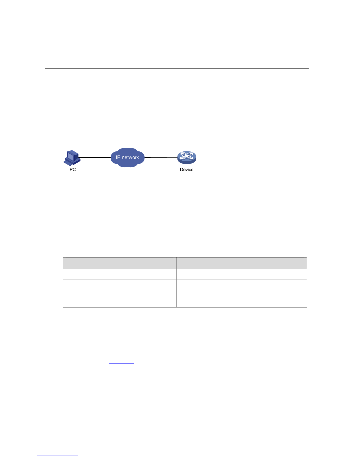
3Com provides the Web-based network management function to facilitate the operations and
maintenance on 3Com’s network devices. Through this function, the administrator can visually manage
and maintain network devices through the Web-based configuration interfaces.
Figure 2-1 shows a Web-based network management operating environment.
Figure 2-1 Web-based network management operating environment
Logging In to the Web Interface
Default Login Information
The device is provided with the default Web login information. You can use the default information to log
in to the Web interface.
Table 2-1 The default Web login information
Information needed at login Default value
Username admin
Password None
IP address of the device (VLAN-interface 1)
Default IP address of the device, depending on the
status of the network where the device resides.
1) The device is not connected to the network, or no DHCP server exists in the subnet where the
device resides
If the device is not connected to the network, or no DHCP server exists in the subnet where the device
resides, you can get the default IP address of the device on the label on the right of the device rear
panel, as shown in
Figure 2-2. The default subnet mask is 255.255.0.0.
Page 10

2-2
Figure 2-2 Default IP address of the device
2) A DHCP server exists in the subnet where the device resides
If a DHCP server exists in the subnet where the device resides, the device will dynamically obtain its
default IP address through the DHCP server. You can log in to the device through the console port, and
execute the summary command to view the information of its default IP address.
<Sysname> summary
Select menu option: Summary
IP Method: DHCP
IP address: 10.153.96.86
Subnet mask: 255.255.255.0
Default gateway: 0.0.0.0
<Omitted>
Example
Assuming that the default IP address of the device is 169.254.147.198, follow these steps to log in to the
device through the Web interface.
z Connect the device to a PC
Connect the GigabitEthernet interface of the device to a PC by using a crossover Ethernet cable (by
default, all interfaces belong to VLAN 1).
z Configure an IP address for the PC and ensure that the PC and device can communicate with each
other properly.
Select an IP address for the PC from network segment 169.254.0.0/16 (except for the default IP
address of the device), for example, 169.254.147.1.
z Open the browser, and input the login information.
On the PC, open the browser (it is recommended to use IE 5.0 or later), type the IP address
http://169.254.147.198 in the address bar, and press Enter to enter the login page of the Web interface,
as shown in
Figure 2-3. Input the username admin and the verification code, leave the password blank,
select the language (English and Chinese are supported at present), and click Login.
Page 11

2-3
Figure 2-3 Login page of the Web interface
z The PC where you configure the device is not necessarily a Web-based network management
terminal. A Web-based network management terminal is a PC used to log in to the Web interface
and is required to be reachable to the device.
z After logging in to the Web interface, you can select Device > Users from the navigation tree,
create a new user, and select Wizard or Network > VLAN interface to configure the IP address of
the VLAN interface acting as the management interface. For detailed configuration, refer to the
corresponding configuration manuals of these modules.
z If you click the verification code displayed on the Web login page, you can get a new verification
code.
z Up to five users can concurrently log in to the device through the Web interface.
Logging Out of the Web Interface
Click Logout in the upper-right corner of the Web interface, as shown in Figure 2-4 to quit the web
console.
The system does not save the current configuration automatically. Therefore, you are recommended to
save the current configuration before logout.
Introduction to the Web Interface
The Web interface is composed of three parts: navigation tree, title area, and body area, as shown in
Figure 2-4.
Page 12
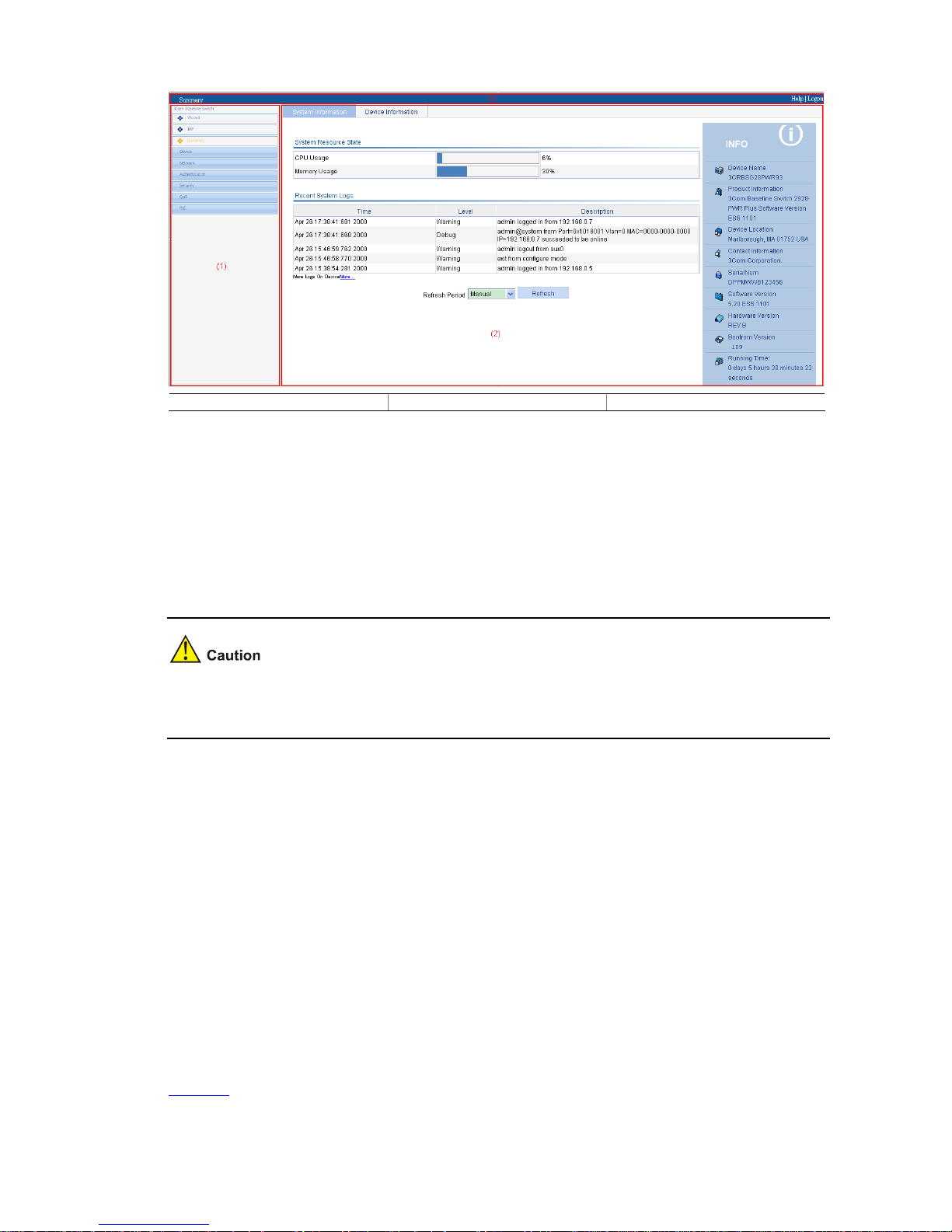
2-4
Figure 2-4 Web-based configuration interface
(1) Navigation tree (2) Body area (3) Title area
z Navigation tree: Organizes the Web-based NM functions as a navigation tree, where you can
select and configure functions as needed. The result is displayed in the body area.
z Body area: Allows you to configure and display features.
z Title area: Displays the path of the current configuration interface in the navigation tree; provides
the Help button to display the Web related help information, and the Logout button to log out of the
Web interface.
The Web network management functions not supported by the device will not be displayed in the
navigation tree.
Web User Level
Web user levels, from low to high, are visitor, monitor, configure, and management. A user with a
higher level has all the operating rights of a user with a lower level.
z Visitor: Users of this level can only use the network diagnostic tools ping and Trace Route. They
can neither access the device data nor configure the device.
z Monitor: Users of this level can only access the device data but cannot configure the device.
z Configure: Users of this level can access device data and configure the device, but they cannot
upgrade the host software, add/delete/modify users, or back up/restore configuration files.
z Management: Users of this level can perform any operations to the device.
Introduction to the Web-Based NM Functions
Table 2-2 describes the Web-based network management functions in detail.
Page 13

2-5
User level in Table 2-2 indicates that users of this level or users of a higher level can perform the
corresponding operations.
Table 2-2 Description of Web-based NM functions
Function menu Description User level
Wizard IP Setup Perform quick configuration of the device. Management
Display global settings and port settings of a stack. Configure
Setup
Configure global parameters and stack ports. Management
Topology
Summary
Display the topology summary of a stack. Configure
IRF
Device
Summary
Display the control panels of stack members. Configure
System
Information
Display the basic system information, system
resource state, and recent system operation logs.
Monitor
Summary
Device
Information
Display the port information of the device. Monitor
System
Name
Display and configure the system name. Configure
Basic
Web Idle
Timeout
Display and configure the idle timeout period for
logged-in users.
Configure
Software
Upgrade
Configure to upload upgrade file from local host,
and upgrade the system software.
Management
Reboot Configure to reboot the device. Management
Electronic
Label
Display the electronic label of the device. Monitor
Device
Mainten
ance
Diagnostic
Information
Generate diagnostic information file, and view or
save the file to local host.
Management
System
Time
System
Time
Display and configure the system date and time. Configure
Display and refresh system logs. Monitor
Loglist
Clear system logs. Configure
Loghost Display and configure the loghost. Configure
Syslog
Log Setup
Display and configure the buffer capacity, and
interval for refreshes system logs.
Configure
Backup
Back up the configuration file to be used at the next
startup from the device to the host of the current
user.
Management
Devi
ce
Configur
ation
Restore
Upload the configuration file to be used at the next
startup from the host of the current user to the
device.
Management
Page 14

2-6
Function menu Description User level
Save
Save the current configuration to the configuration
file to be used at the next startup.
Configure
Initialize Restore the factory default settings. Configure
File
Manage
ment
File
Manageme
nt
Manage files on the device, such as displaying the
file list, downloading a file, uploading a file, and
removing a file.
Management
Summary Display port information by features. Monitor
Detail
Displays feature information by ports. Monitor
Port
Manage
ment
Setup
Create, modify, delete, and enable/disable a port,
and clear port statistics.
Configure
Summary
Display the configuration information of a port
mirroring group.
Monitor
Create Create a port mirroring group. Configure
Remove Remove a port mirroring group. Configure
Port
Mirroring
Modify Port Configure ports for a mirroring group. Configure
Summary
Display the brief information of FTP and Telnet
users.
Monitor
Super
Password
Configure a password for a lower-level user to
switch from the current access level to the
management level.
Management
Create Create an FTP or Telnet user. Management
Modify Modify FTP or Telnet user information. Management
Remove Remove an FTP or a Telnet user. Management
Users
Switch To
Manageme
nt
Switch the current user level to the management
level.
Visitor
Loopbac
k
Loopback Perform loopback tests on Ethernet interfaces. Configure
VCT VCT
Check the status of the cables connected to
Ethernet ports.
Configure
Port Traffic
Statistics
Display the average rate at which the interface
receives and sends packets within a specified time
interval.
Monitor
Flow
Interval
Interval
Configurati
on
Set an interval for collecting traffic statistics on
interfaces.
Configure
Storm
Constrai
n
Storm
Constrain
Display and set the interval for collecting storm
constrain statistics.
Display, create, modify, and remove the port traffic
threshold.
Configure
Statistics Display, create, modify, and clear RMON statistics. Configure
History
Display, create, modify, and clear RMON history
sampling information.
Configure
RMON
Alarm View, create, modify, and clear alarm entries. Configure
Page 15

2-7
Function menu Description User level
Event View, create, modify, and clear event entries. Configure
Log Display log information about RMON events. Configure
Energy
Saving
Energy
Saving
Display and configure the energy saving settings of
an interface.
Configure
Display and refresh SNMP configuration and
statistics information.
Monitor
Setup
Configure SNMP. Configure
Display SNMP community information. Monitor
Community
Create, modify and delete an SNMP community. Configure
Display SNMP group information. Monitor
Group
Create, modify and delete an SNMP group. Configure
Display SNMP user information. Monitor
User
Create, modify and delete an SNMP user. Configure
Display the status of the SNMP trap function and
information about target hosts.
Monitor
Trap
Enable or disable the SNMP trap function, or
create, modify and delete a target host.
Configure
Display SNMP view information. Monitor
SNMP
View
Create, modify and delete an SNMP view. Configure
Interface
Statistics
Interface
Statistics
Display and clear the statistics information of an
interface.
Configure
Select
VLAN
Select a VLAN range. Monitor
Create Create VLANs. Configure
Port Detail Display the VLAN-related details of a port. Monitor
Detail Displays the member port information of a VLAN. Monitor
Modify
VLAN
Modify the description and member ports of a
VLAN.
Configure
Modify Port Change the VLAN to which a port belongs. Configure
VLAN
Remove Remove VLANs. Configure
Summary
Display information about VLAN interfaces by
address type.
Monitor
Create
Create VLAN interfaces and configure IP
addresses for them.
Configure
Modify
Modify the IP addresses and status of VLAN
interfaces.
Configure
VLAN
Interface
Remove Remove VLAN interfaces. Configure
Summary
Display voice VLAN information globally or on a
port.
Monitor
Setup Configure the global voice VLAN. Configure
Net
work
Voice
VLAN
Port Setup Configure a voice VLAN on a port. Configure
Page 16

2-8
Function menu Description User level
OUI
Summary
Display the addresses of the OUIs that can be
identified by voice VLAN.
Monitor
OUI Add
Add the address of an OUI that can be identified by
voice VLAN.
Configure
OUI
Remove
Remove the address of an OUI that can be
identified by voice VLAN.
Configure
Display MAC address information. Monitor
MAC
Create and remove MAC addresses. Configure
MAC
Setup
Display and configure MAC address aging time. Configure
Display information about MST regions. Monitor
Region
Modify MST regions. Configure
Global Set global MSTP parameters. Configure
Port
Summary
Displays the MSTP information of ports. Monitor
MSTP
Port Setup Set MSTP parameters on ports. Configure
Summary Display information about link aggregation groups. Monitor
Create Create link aggregation groups. Configure
Modify Modify link aggregation groups. Configure
Link
Aggrega
tion
Remove Remove link aggregation groups. Configure
Summary
Display information about LACP-enabled ports and
their partner ports.
Monitor
LACP
Setup Set LACP priorities. Configure
Display the LLDP configuration information, local
information, neighbor information, statistics
information, and status information of a port.
Monitor
Port Setup
Modify LLDP configuration on a port. Configure
Display global LLDP configuration information. Monitor
Global
Setup
Configure global LLDP parameters. Configure
Global
Summary
Display global LLDP local information and
statistics.
Monitor
LLDP
Neighbor
Summary
Displays global LLDP neighbor information. Monitor
Display global IGMP snooping configuration
information or the IGMP snooping configuration
information in a VLAN, and view the IGMP
snooping multicast entry information.
Monitor
Basic
Configure IGMP snooping globally or in a VLAN. Configure
Display the IGMP snooping configuration
information on a port.
Monitor
IGMP
Snoopin
g
Advanced
Configure IGMP snooping on a port. Configure
Summary Display the IPv4 active route table. Monitor IPv4
Routing
Create Create an IPv4 static route. Configure
Page 17

2-9
Function menu Description User level
Remove Delete the selected IPv4 static routes. Configure
Display information about the DHCP status,
advanced configuration information of the DHCP
relay agent, DHCP server group configuration,
DHCP relay agent interface configuration, and the
DHCP client information.
Monitor
DHCP
Relay
Enable/disable DHCP, configure advanced DHCP
relay agent settings, configure a DHCP server
group, and enable/disable the DHCP relay agent
on an interface.
Configure
Display the status, trusted and untrusted ports and
DHCP client information of DHCP snooping.
Monitor
DHCP
DHCP
Snooping
Enable/disable DHCP snooping, and configure
DHCP snooping trusted and untrusted ports.
Configure
Displays the states of services: enabled or
disabled.
Configure
Service Service
Enable/disable services, and set related
parameters.
Management
Ping Ping an IPv4 address. Visitor
Diagnost
ic Tools
Trace
Route
Perform trace route operations. Visitor
Display ARP table information. Monitor
ARP Table
Add, modify, and remove ARP entries. Configure
Displays the configuration information of gratuitous
ARP.
Monitor
ARP
Manage
ment
Gratuitous
ARP
Configure gratuitous ARP. Configure
Display ARP detection configuration information. Monitor ARP
Anti-Atta
ck
ARP
Detection
Configure ARP detection. Configure
Display 802.1X configuration information globally
or on a port.
Monitor
802.1X 802.1X
Configure 802.1X globally or on a port. Configure
Display ISP domain configuration information. Monitor
Domain
Setup
Add and remove ISP domains. Management
Display the authentication configuration
information of an ISP domain.
Monitor
Authenticat
ion
Specify authentication methods for an ISP domain. Management
Display the authorization method configuration
information of an ISP domain.
Monitor
Authorizati
on
Specify authorization methods for an ISP domain. Management
Display the accounting method configuration
information of an ISP domain.
Monitor
AAA
Accounting
Specify accounting methods for an ISP domain. Management
Auth
entic
atio
n
RADIUS
RADIUS
Server
Display and configure RADIUS server information. Management
Page 18

2-10
Function menu Description User level
RADIUS
Setup
Display and configure RADIUS parameters. Management
Display configuration information about local
users.
Monitor
Local User
Create, modify and remove a local user. Management
Display configuration information about user
groups.
Monitor
Users
User
Group
Create, modify and remove a user group. Management
Display information about PKI entities. Monitor
Entity
Add, modify, and delete a PKI entity. Configure
Display information about PKI domains. Monitor
Domain
Add, modify, and delete a PKI domain. Configure
Display the certificate information of PKI domains
and view the contents of a certificate.
Monitor
Certificate
Generate a key pair, destroy a key pair, retrieve a
certificate, request a certificate, and delete a
certificate.
Configure
Display the contents of the CRL. Monitor
PKI
CRL
Receive the CRL of a domain. Configure
Summary Display port isolation group information. Monitor Port
Isolate
Group
Modify Configure a port isolation group. Configure
Summary
Display the configurations of authorized IP, the
associated IPv4 ACL list, and the associated IPv6
ACL list.
Management
Sec
urity
Authoriz
ed IP
Setup Configure authorized IP. Management
Summary Display time range configuration information. Monitor
Create Create a time range. Configure
Time
Range
Remove Delete a time range. Configure
Summary Display IPv4 ACL configuration information. Monitor
Create Create an IPv4 ACL. Configure
Basic
Setup
Configure a rule for a basic IPv4 ACL. Configure
Advanced
Setup
Configure a rule for an advanced IPv4 ACL. Configure
Link Setup Create a rule for a link layer ACL. Configure
ACL
IPv4
Remove Delete an IPv4 ACL or its rules. Configure
Summary Display the queue information of a port. Monitor
Queue
Setup Configure a queue on a port. Configure
Summary Display line rate configuration information. Monitor
QoS
Line
Rate
Setup Configure the line rate. Configure
Page 19

2-11
Function menu Description User level
Summary Display classifier configuration information. Monitor
Create Create a class. Configure
Setup Configure the classification rules for a class. Configure
Classifie
r
Remove Delete a class or its classification rules. Configure
Summary Display traffic behavior configuration information. Monitor
Create Create a traffic behavior. Configure
Setup Configure actions for a traffic behavior. Configure
Port Setup
Configuring traffic mirroring and traffic redirecting
for a traffic behavior
Configure
Behavior
Remove Delete a traffic behavior. Configure
Summary Display QoS policy configuration information. Monitor
Create Create a QoS policy. Configure
Setup
Configure the classifier-behavior associations for a
QoS policy.
Configure
QoS
Policy
Remove
Delete a QoS policy or its classifier-behavior
associations.
Configure
Summary Display the QoS policy applied to a port. Monitor
Setup Apply a QoS policy to a port. Configure
Port
Policy
Remove Remove the QoS policy from the port. Configure
Display priority mapping table information. Monitor
Priority
Mapping
Priority
Mapping
Modify the priority mapping entries. Configure
Display port priority and trust mode information. Monitor
Port
Priority
Port
Priority
Modify port priority and trust mode. Configure
Summary
Display PSE information and PoE interface
information.
Monitor
PoE PoE
Setup Configure a PoE interface. Configure
Introduction to the Controls on the Web Pages
Apply button
Click the button to submit and apply the input information.
Cancel button
Click the button to cancel the input information. The page changes to the display page of the function or
to the Device Info page.
Search button
Select an item to be queried, input the keyword, and click the Query button to display the items that
meet the requirements.
Page 20

2-12
The advance search function is also provided. You can click before Search Item, as shown in Figure
2-5. You can select Match case and whole word, that is, the item to be searched must completely
match the keyword, or you can select Search in previous results. If you do not select exact search,
fuzzy search is performed.
Figure 2-5 Advanced search
Refresh button
Click the button to refresh the display information of the current page.
Clear button
Click the button to clear all the items in a list or all statistics.
Remove button
Click the button to remove the selected items.
Select All button
Click the button to select all the items in a list, or all the ports on the device panel.
Select None button
Click the button to deselect all the items in a list, or all the ports on the device panel.
Restore button
Click the button to restore all the items in the current configuration page to the system default.
Expand button
As shown in Figure 2-6, click the plus sign before a corresponding item. You can see the collapsed
contents.
Figure 2-6 Expand button
icon
Click the icon to enter the modification page of an item to modify the configurations of the item.
icon
Click the icon to delete the item corresponding to this icon.
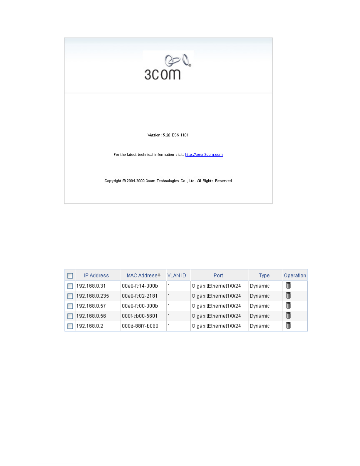
Help button
Click the button to open the page, as shown in Figure 2-8.
Page 21
2-13
Figure 2-7 About
Sort display
On the page, you can click the blue items of each column to sort and display the records based on the
item you selected.
Figure 2-8 Sort display
Configuration Guidelines
z The Web-based console supports Microsoft Internet Explorer 6.0 SP2 and higher, but it does not
support the Back, Next, Refresh buttons provided by the browser. Using these buttons may result
in abnormal display of Web pages.
z When the device is performing spanning tree calculation, you cannot log in to or use the Web
interface.
z As the Windows firewall limits the number of TCP connections, when you use IE to log in to the
Web interface, sometimes you may be unable to open the Web interface. To avoid this problem, it
is recommended to turn off the Windows firewall before login.
Page 22

2-14
z If the software version of the device changes, when you log in to the device through the Web
interface, you are recommended to delete the temporary Internet files of IE; otherwise, the Web
page content may not be displayed correctly.
Page 23

3-1
3 Configuration Through the Command Line
Interface
z The 3Com baseline switch 2900 family can be configured through the command line interface (CLI),
web interface, and SNMP/MIB, among which the web interface supports all switch 2900 series
configurations. These configuration methods are suitable for different application scenarios. As a
supplementary to the web interface, the CLI provides some configuration commands to facilitate
your operation, which are described in this chapter. To perform other configurations not supported
by the CLI, use the web interface.
z You will enter user view directly after you log in to the device. Commands in the document are all
performed in user view.
Getting Started with the Command Line Interface
As a supplementary to the web interface, the CLI provides some configuration commands to facilitate
your operation. For example, if you forget the IP address of VLAN-interface 1 and cannot log in to the
device through the Web interface, you can connect the console port of the device to a PC, and
reconfigure the IP address of VLAN-interface 1 through the CLI.
This section describes using the CLI to manage the device.
Setting Up the Configuration Environment
Set up the configuration environment as follows:
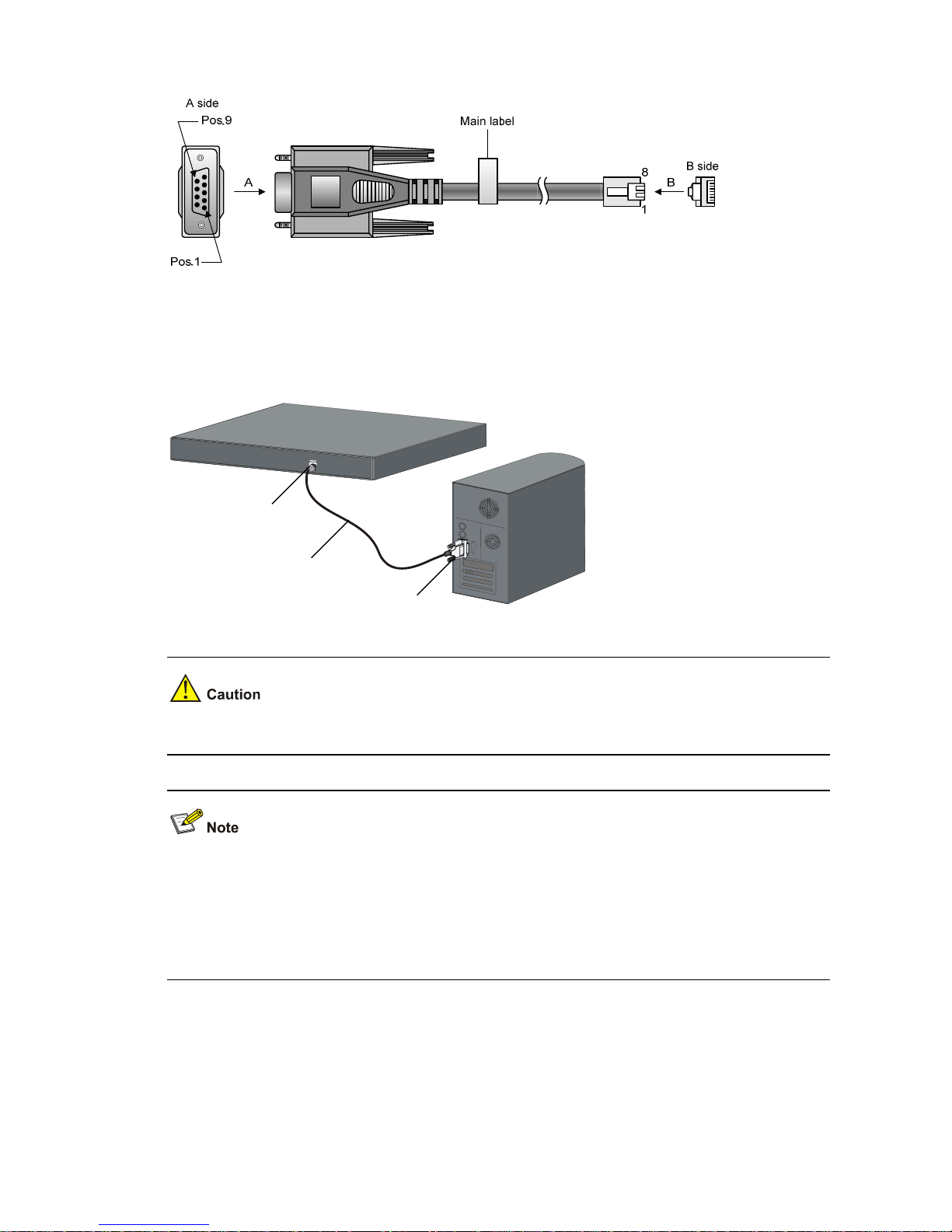
Step1 Take the console cable out of the package. (A console cable is an 8-core shielded cable. One end of the
cable is a crimped RJ-45 connector, which is connected to the console port of the switch, and the other
end is a DB-9 female connector, which is connected to the serial port on the console terminal, as shown
below.)
Page 24
3-2
Figure 3-1 Console cable
Step2 Plug the DB-9 female connector of the console cable to the serial port of the console terminal or PC.
Step3 Connect the RJ-45 connector of the console cable to the console port of the switch. (as shown below)
Figure 3-2 Network diagram for configuration environment setup
Console port
Serial port
Console cable
Pay attention to the mark on the console port and be sure to plug the connector to the correct port.
z When connecting a PC to a powered-on switch, you are recommended to connect the DB-9
connector of the console cable to the PC before connecting the RJ-45 connector to the switch.
z When disconnecting a PC from a powered-on switch, you are recommended to disconnect the
DB-9 connector of the console cable from the PC after disconnecting the RJ-45 connector from the
switch.
Setting Terminal Parameters
When setting up the configuration environment through the console port, the terminal or PC can use the
terminal emulation program to communicate with the switch. You can run the HyperTerminal of the
Windows operating system to connect to other PCs, network devices, and Telnet sites. For detailed
Page 25
3-3
information and the use of the HyperTerminal, refer to the HyperTerminal Help documentation in Help
and Support Center on the PC running the Windows operating system.
In the following configuration procedure, Windows XP HyperTerminal is used to communicate with the
switch.
1) Start the PC and run the terminal emulation program.
2) Set terminal parameters as follows:
z Bits per second: 38,400
z Data bits: 8
z Parity: None
z Stop bits: 1
z Flow control: None
z Emulation: VT100
The specific procedure is as follows:
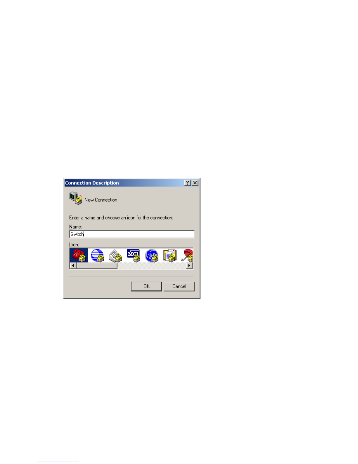
Step1 Select Start > Programs > Accessories > Communications > HyperTerminal to enter the
HyperTerminal window. The Connection Descriptio n dialog box appears, as shown below.
Figure 3-3 Connection description of the HyperTerminal
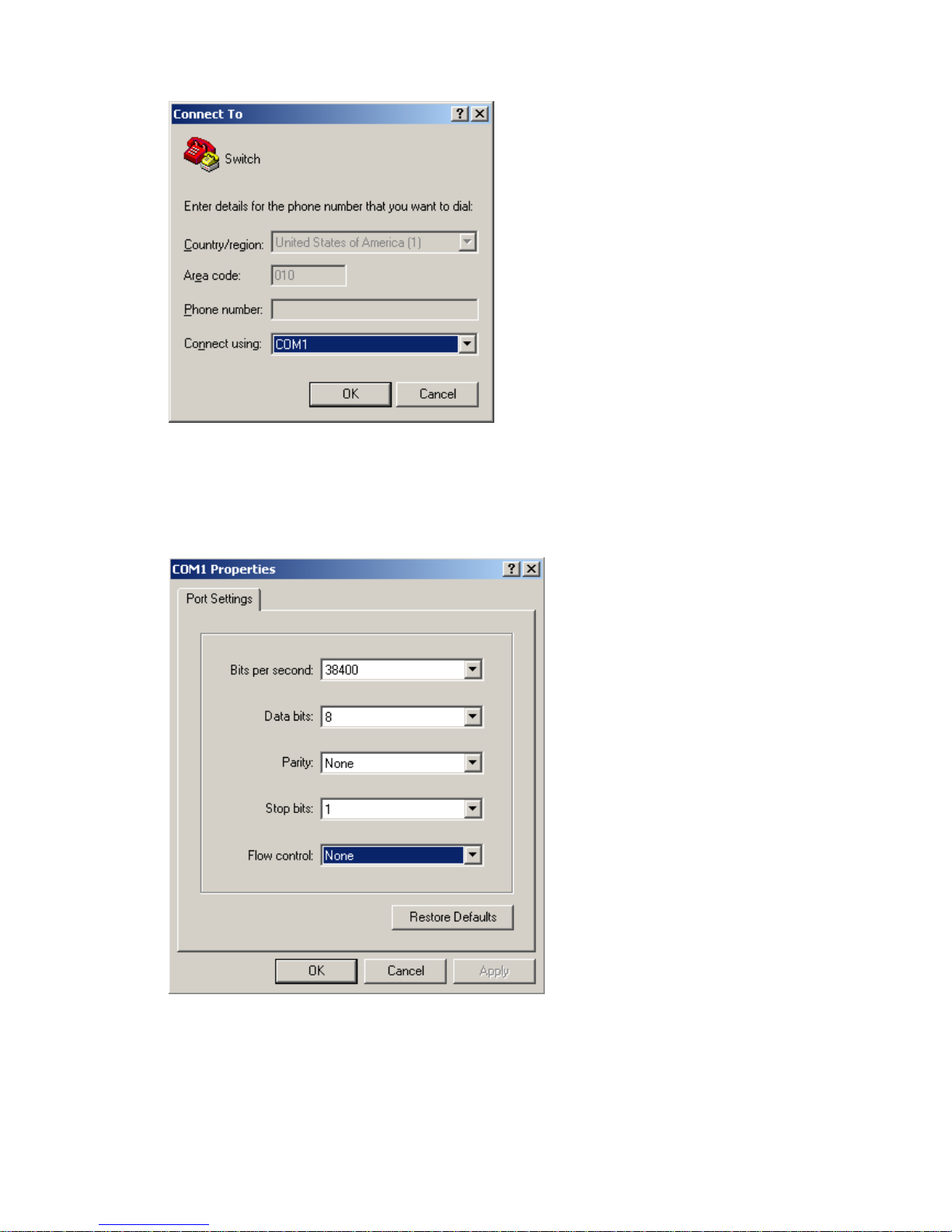
Step2 Type the name of the new connection in the Name text box and click OK. The following dialog box
appears. Select the serial port to be used from the Connect using drop-down list.
Page 26
3-4
Figure 3-4 Set the serial port used by the HyperTerminal connection
Step3 Click OK after selecting a serial port. The following dialog box appears. Set Bits per second to 38400,
Data bits to 8, Parity to None, Stop bits to 1, and Flow control to None.
Figure 3-5 Set the serial port parameters
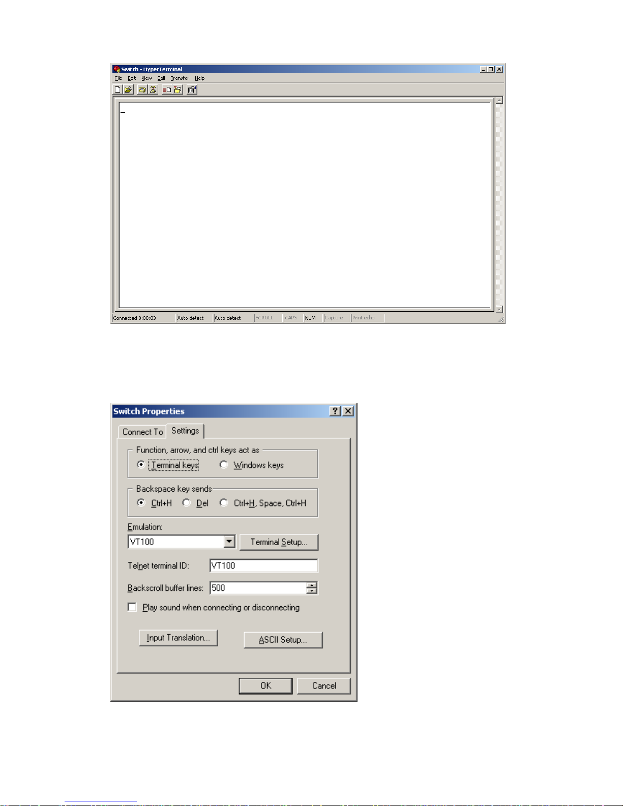
Step4 Click OK after setting the serial port parameters and the system enters the HyperTerminal window
shown below.
Page 27
3-5
Figure 3-6 HyperTerminal window
Step5 Click Properties in the HyperTerminal window to enter the Switch Properties dialog box. Click the
Settings tab, set the emulation to VT100, and then click OK.
Figure 3-7 Set terminal emulation in Switch Properties dialog box
Page 28

3-6
Logging In to the CLI
The login process requires a user name and password. The default user name for first time
configuration is admin, no password is required. User names and passwords are case sensitive.
To logon to the CLI Interface:
Step1 Press Enter. The Username prompt displays:
Login authentication
Username:
Step2 Enter your User Name at the Username prompt.
Username:admin
Step3 Press Enter. The Password prompt display
Password:
The login information is verified, and displays the following CLI menu:
<3Com Baseline Switch>
If the password is invalid, the following message appears and process restarts.
% Login failed!
CLI Commands
This Command section contains the following commands:
To do… Use the command…
Displays a list of CLI commands on the device
?
Reboot the device and run the default configuration
initialize
Specify VLAN-interface 1 to obtain an IP address
through DHCP or manual configuration
ipsetup { dhcp | ip address ip-address
{ mask | mask-length } [ default-gateway
ip-address ] }
Modify the login password of a user
password
Download the Boot ROM program or boot file from the
TFTP server and specify it to be used at the next startup
upgrade server-address source-filename
{ bootrom | runtime }
Reboot the device and run the main configuration file
reboot
View the summary information of the device
summary
Ping a specified destination
ping host
initialize
Syntax
initialize
Parameters
None
Page 29

3-7
Description
Use the initialize command to delete the configuration file to be used at the next startup and reboot the
device with the default configuration being used during reboot.
Use the command with caution because this command deletes the configuration file to be used at the
next startup and restores the factory default settings.
Examples
# Delete the configuration file to be used at the next startup and reboot the device with the default
configuration being used during reboot.
<Sysname> initialize
The startup configuration file will be deleted and the system will be rebooted.Continue?
[Y/N]:y
Please wait...
ipsetup
Syntax
ipsetup { dhcp | ip address ip-address { mask | mask-length } [ default-gateway ip-address ] }
Parameters
dhcp: Specifies the interface to obtain an IP address through DHCP.
ip-address ip-address: Specifies an IP address for VLAN-interface 1 in dotted decimal notation.
mask: Subnet mask in dotted decimal notation.
mask-length: Subnet mask length, the number of consecutive ones in the mask, in the range of 0 to 32.
default-gateway ip-address: Specifies the IP address of the default gateway or the IP address of the
outbound interface. With this argument and keyword combination configured, the command not only
assigns an IP address to the interface, but also specifies a default route for the device.
Description
Use the ipsetup dhcp command to specify VLAN-interface 1 to obtain an IP address through DHCP.
Use the ipsetup ip address ip-address { mask | mask-length } command to assign an IP address to
VLAN-interface 1.
By default, the device automatically obtains its IP address through DHCP; if fails, it uses the assigned
default IP address. See
Figure 2-2 for details.
If there is no VLAN-interface 1, either command creates VLAN-interface 1 first, and then specifies its IP
address.
Examples
# Create VLAN-interface 1 and specify the interface to obtain an IP address through DHCP.
<Sysname> ipsetup dhcp
# Create VLAN-interface 1 and assign 192.168.1.2 to the interface, and specify 192.168.1.1 as the
default gateway.
<Sysname> ipsetup ip-address 192.168.1.2 24 default-gateway 192.168.1.1
Page 30

3-8
password
Syntax
password
Parameters
None
Description
Use the password command to modify the login password of a user.
Examples
# Modify the login password of user admin.
<Sysname> password
Change password for user: admin
Old password: ***
Enter new password: **
Retype password: **
The password has been successfully changed.
ping
Syntax
ping host
Parameters
host: Destination IP address (in dotted decimal notation), URL, or host name (a string of 1 to 20
characters).
Description
Use the ping command to ping a specified destination.
You can enter Ctrl+C to terminate a ping operation.
Examples
# Ping IP address 1.1.2.2.
<Sysname> ping 1.1.2.2
PING 1.1.2.2: 56 data bytes, press CTRL_C to break
Reply from 1.1.2.2: bytes=56 Sequence=1 ttl=254 time=205 ms
Reply from 1.1.2.2: bytes=56 Sequence=2 ttl=254 time=1 ms
Reply from 1.1.2.2: bytes=56 Sequence=3 ttl=254 time=1 ms
Reply from 1.1.2.2: bytes=56 Sequence=4 ttl=254 time=1 ms
Reply from 1.1.2.2: bytes=56 Sequence=5 ttl=254 time=1 ms
--- 1.1.2.2 ping statistics -- 5 packet(s) transmitted
5 packet(s) received
0.00% packet loss
Page 31

3-9
round-trip min/avg/max = 1/41/205 ms
The above information shows that IP address 1.1.2.2 is reachable and the echo replies are all returned
from the destination. The minimum, average, and maximum roundtrip intervals are 1 millisecond, 41
milliseconds, and 205 milliseconds respectively.
quit
Syntax
quit
Parameters
None
Description
Use the quit command to log out of the system.
Examples
# Log out of the system.
<Sysname> quit
******************************************************************************
* Copyright (c) 2004-2009 3Com Corp. and its licensors. All rights reserved. *
* This software is protected by copyright law and international treaties. *
* Without the prior written permission of 3Com Corporation and its licensors,*
* any reproduction republication, redistribution, decompiling, reverse *
* engineering is strictly prohibited. Any unauthorized use of this software *
* or any portion of it may result in severe civil and criminal penalties, and*
* will be prosecuted to the maximum extent possible under the applicable law.*
******************************************************************************
User interface aux0 is available.
Please press ENTER.
reboot
Syntax
reboot
Parameters
None
Description
Use the reboot command to reboot the device and run the main configuration file.
Note that:
z Use the command with caution because reboot results in service interruption.
Page 32

3-10
z If the main configuration file is corrupted or does not exist, the device cannot be rebooted with the
reboot command. In this case, you can specify a new main configuration file to reboot the device,
or you can power off the device, and then power it on, and the system will automatically use the
backup configuration file at the next startup.
z If you reboot the device when file operations are being performed, the system does not execute the
command to ensure security.
Examples
# If the configuration does not change, reboot the device.
<Sysname> reboot
Start to check configuration with next startup configuration file, please wait.........DONE!
This command will reboot the device. Continue? [Y/N]:y
Now rebooting, please wait...
# If the configuration changes, reboot the device.
<Sysname> reboot
Start to check configuration with next startup configuration file, please wait.........DONE!
This command will reboot the device. Current configuration will be lost in next startup if
you continue. Continue? [Y/N]:y
Now rebooting, please wait...
summary
Syntax
summary
Parameters
None
Description
Use the summary command to view the summary information of the device, including the IP address of
VLAN-interface 1, and software version information.
Examples
# Display summary information of the device.
<Sysname> summary
Select menu option: Summary
IP Method: DHCP
IP address: 10.153.96.86
Subnet mask: 255.255.255.0
Default gateway: 0.0.0.0
Current boot app is: flash:/2900_release.bin
Next main boot app is: NULL
Next backup boot app is: NULL
3Com Corporation
3Com Baseline Switch 2928-PWR Plus Software Version 5.20 ESS 1101
Page 33

3-11
Copyright (c) 2004-2009 3Com Corp. and its licensors. All rights reserved.
3Com Baseline Switch 2928-PWR Plus uptime is 0 week, 0 day, 3 hours, 11 minutes
3Com Baseline Switch 2928-PWR Plus
128M bytes DRAM
128M bytes Nand Flash Memory
Config Register points to Nand Flash
Hardware Version is REV.B
CPLD Version is 001
Bootrom Version is 112
[SubSlot 0] 24GE+4SFP+POE Hardware Version is REV.B
upgrade
Syntax
upgrade server-address source-filename { bootrom | runtime }
Parameters
server-address: IP address or host name (a string of 1 to 20 characters) of a TFTP server.
source-filename: Software package name on the TFTP server.
bootrom: Specifies the Boot ROM file in the software package to be used at the next startup.
runtime: Specifies the boot file in the software package to be used at the next startup.
Description
Use the upgrade server-address source-filename bootrom command to upgrade the Boot ROM file. If
the Boot ROM file in the downloaded software package is not applicable, the original Boot ROM
program is still used at the next startup.
Use the upgrade server-address source-filename runtime command to upgrade the boot file. If the
boot file in the downloaded software package is not applicable, the original boot file is still used at the
next startup.
To make the downloaded package take effect, you need to reboot the device.
The Switch 2900 series does not provide an independent Boot ROM file; instead, it integrates the Boot
ROM file with the boot file together in a software package with the extension name of .bin.
Examples
# Download software package main.bin from the TFTP server and use the Boot ROM file in the
package at the next startup.
<Sysname> upgrade 192.168.20.41 main.bin bootrom
Page 34

3-12
# Download software package main.bin from the TFTP server and use the boot file in the package at
the next startup.
<Sysname> upgrade 192.168.20.41 main.bin runtime
Configuration Example for Upgrading the Host Software Through
the CLI
Network requirements
As shown in Figure 3-8, a Switch 2900 series switch is connected to the PC through the console cable,
and connected to the gateway through GigabitEthernet 1/0/1. The IP address of the gateway is
192.168.1.1/24, and that of the TFTP server where the host software (suppose its name is
Switch2900.bin) is located is 192.168.10.1/24. The route between the gateway and the switch is
reachable.
The administrator upgrades the Boot ROM and the system boot file of the 2900 switch through the
configuration PC and sets the IP address of the switch to 192.168.1.2/24.
Figure 3-8 Network diagram for upgrading the host software of the 2900 switch through CLI
Configuration procedure
1) Run the TFTP server program on the TFTP server, and specify the path of the program to be
loaded. (Omitted)
2) Perform the following configurations on the switch.
# Configure the IP address of VLAN-interface 1 of the switch as 192.168.1.2/24, and specify the default
gateway as 192.168.1.1.
<Switch> ipsetup ip-address 192.168.1.2 24 default-gateway 192.168.1.1
# Download the host software package Switch2900.bin on the TFTP server to the switch, and specify it
as the boot file for the next system boot.
<Switch> upgrade 192.168.10.1 Switch2900.bin runtime
File will be transferred in binary mode
Downloading file from remote TFTP server, please wait...|
TFTP: 253700 bytes received in 2 second(s)
File downloaded successfully.
BootRom file updating finished!
# Download the host software package Switch2900.bin on the TFTP server to the switch, and specify it
as the Boot ROM file for the next system boot.
<Switch> upgrade 192.168.10.1 Switch2900.bin bootrom
The file flash:/ Switch2900.bin exists. Overwrite it? [Y/N]:y
Verifying server file...
File will be transferred in binary mode
Downloading file from remote TFTP server, please wait.../
TFTP: 9711592 bytes received in 186 second(s)
Page 35

3-13
File downloaded successfully.
The specified file will be used as the boot file at the next reboot.
# Reboot the switch.
<Switch> reboot
After getting the new application file, reboot the switch to have the upgraded application take effect.
Page 36

Table of Contents
1 Configuration Wizard ································································································································1-1
Overview ·················································································································································1-1
Basic Service Setup ································································································································1-1
Entering the Configuration Wizard Homepage················································································1-1
Configuring System Parameters ·····································································································1-1
Configuring Management IP Address ·····························································································1-3
Finishing Configuration Wizard ·······································································································1-4
i
Page 37

1-1
1 Configuration Wizard
Ove
The configuration wizard guides you through the basic service setup, including the system name,
d management IP address (IP address of the VLAN interface).
Enter
uration wizard homepage, as shown in
rview
system location, contact information, an
Basic Service Setup
ing the Configuration Wizard Homepage
From the navigation tree, select Wizard to enter the config
Figure 1-1.
Figure 1-1 Configuration wizard homepage
Conf
In the wizard homepage, click Next to enter the system parameter configuration page, as shown in
Figure 1-2
iguring System Parameters
.
Page 38

1-2
e Figure 1-2 System parameter configuration pag
Table 1-1 describes the system parameter configuration items.
Table 1-1 System parameter configuration items
Item Description
Sysname
Specify the system name.
The system name appears at the top of the navigation tree.
You can also set the system name in the System Name page you enter by
selecting Device > Basic. For details, refer to Device Basic Inform at ion
Configuration.
Syslocation
Specify the physical location of the system.
You can also set the physical location in the setup page you enter by selecting
Device > SNMP. For details, refer to SNMP Configuration.
Syscontact
Set the contact information for users to get in touch with the device vendor for
help.
You can also set the contact information in the setup page you enter by
selecting Device > SNMP. For details, refer to SNMP Configuration.
Page 39

1-3
Configuring Management IP Address
Modifying the management IP address used for the current login will tear down the connection to the
device. Use the new management IP address to re-log in to the system.
A management IP address is the IP address of a VLAN interface, which can be used to access the
device. You can also set configure a VLAN interface and its IP address in the page you enter by
selecting Network > VLAN Interface. For configuration details, refer to VLAN Interface Conf iguration.
After finishing the configuration, click Next to enter the management IP address configuration page, as
shown in
Figure 1-3.
Figure 1-3 Management IP address configuration page
Table 1-2 describes the configuration items for configuring a management IP address.
Page 40

1-4
Table 1-2 Management IP address configuration items
Item Description
Select VLAN
Interface
Select a VLAN interface.
Available VLAN interfaces are those configured in the page you enter by selecting
Network > VLAN Interface and selecting the Create tab.
Admin
Status
Enable or disable the VLAN interface.
When errors occurred on the VLAN interface, disable the interface and then enable
the port to bring the port to work properly.
By default, the VLAN interface is down if no Ethernet ports in the VLAN is up. The
VLAN is in the up state if one or more ports in the VLAN are up.
Disabling or enabling the VLAN interface does not affect the status of the Ethernet
ports in the VLAN. That is, the port status does not change with the VLAN interface
status.
DHCP
BOOTP
Manual
Configure how the VLAN interface obtains an IPv4 address.
z DHCP: Specifies the VLAN interface to obtain an IPv4 address
by DHCP.
z BOOTP: Specifies the VLAN interface to obtain an IPv4 address
through BOOTP.
z Manual: Allows you to specify an IPv4 address and a mask
length.
Support for IPv4 obtaining methods depends on the device model.
IPv4 address
Configure
IPv4
address
MaskLen
Specify an IPv4 address and the mask length for the VLAN interface.
These two text boxes are configurable if Manual is selected.
Finishing Configuration Wizard
After finishing the management IP address configuration, click Next, as shown in Figure 1-4.
Page 41

1-5
s Figure 1-4 Configuration finishe
The page displays your configurations. Review the configurations and if you want to modify the settings
click Back to go back to the page. Click Finish to confirm your settings and the system performs the
configurations.
Page 42

i
Table of Contents
1 IRF·······························································································································································1-1
IRF Overview ··········································································································································1-1
Introduction to Stack························································································································1-1
Establishing a Stack ························································································································1-1
Configuring an IRF Stack························································································································1-2
Configuration Task List····················································································································1-2
Configuring Global Parameters of a Stack······················································································1-3
Configuring Stack Ports···················································································································1-4
Displaying Topology Summary of a Stack·······················································································1-4
Displaying Device Summary of a Stack ··························································································1-5
Logging Into a Slave Device From the Master ················································································1-5
IRF Stack Configuration Example···········································································································1-6
Configuration Guidelines·······················································································································1-11
Page 43

1-1
1 IRF
IRF Overview
An Intelligent Resilient Framework (IRF) stack is a set of network devices. Administrators can group
multiple network devices into a stack and manage them as a whole. Therefore, stack management can
help reduce customer investments and simplify network management.
Introduction to Stack
A stack is a management domain that comprises several network devices connected to one another
through stack ports. In a stack, there is a master device and several slave devices.
An administrator can manage all the devices in a stack through the master device.
Figure 1-1 shows a
network diagram for stack management.
Figure 1-1 Network diagram for stack management
z Master device: In a stack, the master device acts as the configuration interface in stack
management. Management and monitoring of all the devices in the stack are performed through
the master device.
z Slave devices: Managed devices in a stack.
z Stack port: Ports between stack devices.
Establishing a Stack
An administrator can establish a stack as follows:
z Configure a private IP address pool for a stack and create the stack on the network device which is
to be configured as the master device.
z Configure ports between the stack devices as stack ports.
z The master device automatically adds the slave devices into the stack, and allocates a private IP
address and a member ID for each slave device.
Page 44

1-2
z The administrator can log in to any slave device from the master device of the stack, and perform
various configurations for the slave device.
Configuring an IRF Stack
Configuration Task List
Perform the tasks in Table 1-1 to configure an IRF stack.
Table 1-1 Stack configuration task list
Task Remarks
Configuring
Global
Parameters of a
Stack
Required
Configure a private IP address pool for a stack and establish the
stack, and meantime the device becomes the master device of
the stack.
By default, no IP address pool is configured for a stack and no
stack is established.
Configuring
the master
device of a
stack
Configuring Stack
Ports
Required
Configure the ports of the master device that connect to slave
devices as stack ports.
By default, a port is not a stack port.
Configuring
slave
devices of a
stack
Configuring Stack
Ports
Required
Configure a port of a slave device that connects to the master
device or another slave device as a stack port.
By default, a port is not a stack port.
Displaying Topology Summary of
a Stack
Optional
Display the information of stack members.
Displaying Device Summary of a
Stack
Optional
Display the control panels of stack members.
Before viewing the control panel of a slave device, you must
ensure that the username, password, and access right you used
to log on to the master device are the same with those
configured on the slave device; otherwise, the control panel of
the slave device cannot be displayed.
Logging Into a Slave Device
From the Master
Optional
Log in to the web network management interface of a slave
device from the master device.
Before logging into a slave device, you must ensure that the
username, password, and access right you used to log on to the
master device are the same with those configured on the slave
device; otherwise, you cannot log into the slave device. You can
configure them by selecting Device and then clicking Users
from the navigation tree.
Page 45

1-3
Configuring Global Parameters of a Stack
Select IRF from the navigation tree to enter the page shown in Figure 1-2. You can configure global
parameters of a stack in the Global Settings area.
Figure 1-2 Set up
Table 1-2 describes configuration items of global parameters.
Page 46

1-4
Table 1-2 Configuration items of global parameters
Item Description
Private Net IP
Mask
Configure a private IP address pool for the stack.
The master device of a stack must be configured with a private IP address
pool to ensure that it can automatically allocate an available IP address to a
slave device when the device joints the stack.
When you configure a private IP address pool for a stack, the number of IP
addresses in the address pool needs to be equal to or greater than the
number of devices to be added to the stack. Otherwise, some devices may
not be able to join the stack automatically for lack of private IP addresses.
Build Stack
Enable the device to establish a stack.
After you enable the device to establish a stack, the device becomes the
master device of the stack and automatically adds the devices connected to
its stack ports to the stack.
You can delete a stack only on the master device of the stack. The Global
Settings area on a slave device is grayed out.
Return to
Stack configuration task list.
Configuring Stack Ports
Select IRF from the navigation tree to enter the page shown in Figure 1-2. You can configure stack ports
in the Port Settings area.
z Select the check box before a port name, and click Enable to configure the port as a stack port.
z Select the check box before a port name, and click Disable to configure the port as a non-stack
port.
Return to
Stack configuration task list.
Displaying Topology Summary of a Stack
Select IRF from the navigation tree and click the Topology Summary tab to enter the page shown in
Figure 1-3.
Figure 1-3 Topology summary
Table 1-3 describes the fields of topology summary.
Page 47

1-5
Table 1-3 Fields of topology summary
Fields Description
Member ID
Member ID of the device in the stack:
z Value 0 indicates that the device is the master device of the stack.
z A value other than 0 indicates that the device is a slave device and the
value is the member ID of the slave device in the stack.
Role Role of the device in the stack: master or slave.
Return to
Stack configuration task list.
Displaying Device Summary of a Stack
Select IRF from the navigation tree and click the Device Summary tab to enter the page shown in
Figure 1-4. On this page, you can view interfaces and power socket layout on the panel of each stack
member by clicking the tab of the corresponding member device.
Figure 1-4 Device summary (the master device)
Return to
Stack configuration task list.
Logging Into a Slave Device From the Master
Select IRF from the navigation tree, click the Device Summary tab, and click the tab of a slave device
to enter the page shown in
Figure 1-5.
Click the Configuring the Device hyperlink, you can log on to the web interface of the slave device to
manage and maintain the slave device directly.
Page 48

1-6
Figure 1-5 Device summary (a slave device)
Return to
Stack configuration task list.
IRF Stack Configuration Example
Network requirements
z As shown in Figure 1-6, Switch A, Switch B, Switch C, and Switch D are connected with one
another.
z Create a stack, where Switch A is the master device, Switch B, Switch C, and Switch D are slave
devices. An administrator can log in to Switch B, Switch C and Switch D through Switch A to
perform remote configurations.
Figure 1-6 Network diagram for IRF stack
GE1/0/1
GE1/0/3
SwitchB: Slave device
GE1/0/1GE1/0/1
SwitchC: Slave device SwitchD: Slave device
Stack
GE1/0/1
GE1/0/2
SwitchA: Master device
Configuration procedure
1) Configure the master device
# Configure global parameters for the stack on Switch A.
z Select IRF from the navigation tree of Switch A to enter the page of the Setup tab, and then
perform the following configurations, as shown in
Figure 1-7.
Page 49

1-7
Figure 1-7 Configure global parameters for the stack on Switch A
z Type 192.168.1.1 in the text box of Private Net IP.
z Type 255.255.255.0 in the text box of Mask.
z Select Enable from the Build Stack drop-down list.
z Click Apply.
Now, switch A becomes the master device.
# Configure a stack port on Switch A.
z On the page of the Setup tab, perform the following configurations, as shown in Figure 1-8.
Page 50

1-8
Figure 1-8 Configure a stack port on Switch A
z In the Port Settings area, select the check box before GigabitEthernet1/0/1.
z Click Enable.
2) Configure the slave devices
# On Switch B, configure local ports GigabitEthernet 1/0/2 connecting with switch A, GigabitEthernet
1/0/1 connecting with Switch C, and GigabitEthernet 1/0/3 connecting with Switch D as stack ports.
z Select IRF from the navigation tree of Switch B to enter the page of the Setup tab, and then
perform the following configurations, as shown in
Figure 1-9.
Page 51

1-9
Figure 1-9 Configure stack ports on Switch B
z In the Port Settings area, select the check boxes before GigabitEthernet1/0/1,
GigabitEthernet1/0/2, and GigabitEthernet1/0/3.
z Click Enable.
Now, switch B becomes a slave device.
# On Switch C, configure local port GigabitEthernet 1/0/1 connecting with Switch B as a stack port.
z Select IRF from the navigation tree of Switch C to enter the page of the Setup tab, and then
perform the following configurations, as shown in
.
Page 52

1-10
Figure 1-10 Configure a stack port on Switch C
z In the Port Settings area, select the check box before GigabitEthernet1/0/1.
z Click Enable.
Now, Switch C becomes a slave device.
# On Switch D, configure local port GigabitEthernet 1/0/1 connecting with Switch B as a stack port.
z Select IRF from the navigation tree of Switch D to enter the page of the Setup tab, and then
perform the following configurations, as shown in
Figure 1-10.
z In the Port Settings area, select the check box before GigabitEthernet1/0/1.
z Click Enable.
Page 53

1-11
Now, Switch D becomes a slave device.
3) Verify the configuration
# Display the stack topology on Switch A.
z Select IRF from the navigation tree of Switch A and click the Topology Summary tab.
z You can view the information as shown in Figure 1-11.
Figure 1-11 Verify the configuration
Configuration Guidelines
When configuring an IRF stack, note that:
1) If a device is already configured as the master device of a stack, you are not allowed to modify the
private IP address pool on the device.
2) If a device is already configured as a slave device of a stack, the Global Settings area on the slave
device is grayed out.
Page 54

i
Table of Contents
1 Summary ····················································································································································1-1
Overview ·················································································································································1-1
Displaying Device Summary ···················································································································1-1
Displaying System Information········································································································1-1
Displaying Device Information·········································································································1-2
Page 55

1-1
1 Summary
Overview
The device summary module helps you understand the system information, port information, power
information, and fan information on the device. The system information includes the basic system
information, system resources state, and recent system operation logs.
Displaying Device Summary
Displaying System Information
After you log in to the Web interface, the System Information page appears by default, as shown in
Figure 1-1.
Figure 1-1 System information
Select from the Refresh Period drop-down list:
z If you select a certain period, the system refreshes the system information at the specified interval.
z If you select Manual, the system refreshes the information only when you click the Refresh button.
The system information page is divided into three sections, which display:
z Basic system information
z System resource state
z Recent system operation logs
Page 56

1-2
Basic system information
The INFO area on the right of the page displays the basic system information including device name,
product information, device location, contact information, serial number, software version, hardware
version, BootROM version, and running time. The running time displays how long the device is up since
the last boot.
You can configure the device location and contact information on the Setup page you enter by selecting
Device > SNMP.
System resource state
The System Resource State displays the most current CPU usage and memory usage.
Recent system operation logs
Table 1-1 describes the fields in the recent system operation log table.
Table 1-1 Description about the recent system operation logs
Field Description
Time This field displays the time when the system operation logs are generated.
Level This field displays the severity of the system operation logs.
Description This field displays the description of the system operation logs.
z The Summary page displays up to five the most recent system operation logs about the login and
logout events.
z For more system operation logs, you can click More to enter the Log List page. You can also enter
this page by selecting Device > Syslog. For details, refer to Log Management Configuration.
Displaying Device Information
After you log in to the Web interface, you can click the Device Information tab to enter the page
displaying the device ports. Hover the cursor over a port and the port details appears, including the port
name, type, speed, utilization, and status, as shown in
Figure 1-2. For the description about the port
number and its color, see
Figure 1-2. Similarly, you can also view the power type and working status and
the fan working status.
Page 57

1-3
Figure 1-2 Device information
Select from the Refresh Period drop-down list:
z If you select a certain period, the system refreshes the information at the specified interval.
z If you select Manual, the system refreshes the information only when you click the Refresh button.
Page 58

i
Table of Contents
1 Device Basic Information Configuration·································································································1-1
Overview ·················································································································································1-1
Configuring Device Basic Information·····································································································1-1
Configuring System Name ··············································································································1-1
Configuring Idle Timeout Period······································································································1-1
Page 59

1-1
1 Device Basic Information Configuration
Overview
The device basic information feature provides you the following functions:
z Set the system name of the device. The configured system name will be displayed on the top of the
navigation bar.
z Set the idle timeout period for a logged-in user. That is, the system will log an idle user off the Web
for security purpose after the configured period.
Configuring Device Basic Information
Configuring System Name
Select Device > Basic from the navigation tree to enter the system name page, as shown in Figure 1-1.
Figure 1-1 System name
Table 1-1 describes the system name configuration item.
Table 1-1 System name configuration item
Item Description
Sysname Set the system name.
Configuring Idle Timeout Period
Select Device > Basic from the navigation tree to enter the idle timeout page, as shown in Figure 1-2.
Page 60

1-2
Figure 1-2 Configuring idle timeout period
Table 1-2 describes the idle timeout period configuration item.
Table 1-2 Idle timeout period configuration item
Item Description
Idle timeout Set the idle timeout period for a logged-in user.
Page 61

i
Table of Contents
1 System Time Configuration······················································································································1-1
Overview ·················································································································································1-1
Configuring System Time························································································································1-1
System Time Configuration Example······································································································1-2
Configuration Guidelines·························································································································1-3
Page 62

1-1
1 System Time Configuration
Overview
The system time module allows you to display and set the device system time on the Web interface.
The device supports setting system time through manual configuration and automatic synchronization
of NTP server time.
An administrator can by no means keep time synchronized among all the devices within a network by
changing the system clock on each device, because this is a huge amount of workload and cannot
guarantee the clock precision.
Defined in RFC 1305, the Network Time Protocol (NTP) synchronizes timekeeping among distributed
time servers and clients. NTP allows quick clock synchronization within the entire network and ensures
a high clock precision so that the devices can provide diverse applications based on the consistent time.
Configuring System Time
Select System > Sy stem T ime from the navigation tree to enter the system time configuration page, as
shown in
Figure 1-1. On the upper side of the interface, the current system time and clock status are
displayed, and you can click Refresh to refresh the displayed content; on the lower side of the interface,
you can set the system time.
Figure 1-1 System time configuration page
Page 63

1-2
Table 1-1 shows the system time configuration items.
Table 1-1 System time configuration items
Item Description
Manual
Select to manually configure the system time, including the
setting of Year, Month, Day, Hour, Minute, and Second.
Source Interface
Set the source interface for an NTP message.
If you do not want the IP address of a certain interface on the
local device to become the destination address of response
messages, you can specify the source interface for NTP
messages, so that the source IP address in the NTP
messages is the primary IP address of this interface.
Key 1
Key 2
Set NTP authentication key.
The NTP authentication feature should be enabled for a
system running NTP in a network where there is a high
security demand. This feature enhances the network security
by means of client-server key authentication, which prohibits a
client from synchronizing with a device that has failed
authentication.
You can set two authentication keys, each of which is
composed of a key ID and key string.
z ID is the ID of a key.
z Key string is a character string for MD5 authentication key.
NTP Server
1/Reference
Key ID
NTP
External
Reference
Source
NTP Server
2/Reference
Key ID
Specify the IP address of an NTP server, and configure the
authentication key ID used for the association with the NTP
server. Only if the key provided by the server is the same with
the specified key will the device synchronize its time to the
NTP server.
You can configure two NTP servers. The clients will choose
the optimal reference source.
The IP address of an NTP server is a unicast address, and
cannot be a broadcast or a multicast address, or the IP
address of the local clock source.
System Time Configuration Example
Network requirements
z As shown in Figure 1-2, the local clock of Device A is set as the reference clock.
z Switch B works in the client mode, and uses Device A as the NTP server.
z Configure NTP authentication on Device A and Switch B.
Figure 1-2 Network diagram for configuring system time
Device A Switch B
1.0.1.11/24 1.0.1.12/24
Page 64

1-3
Configuration procedure
1) Configure Device A
# Configure the local clock as the reference clock, with the stratum of 2. Enable NTP authentication, set
the key ID to 24, and specify the created authentication key aNiceKey is a trusted key. (Configuration
omitted.)
2) Configure Switch B
# Configure Device A as the NTP server of Switch B.
z Select System > System Time from the navigation tree and perform the configurations as shown
in
Figure 1-3.
Figure 1-3 Configure Device A as the NTP server of Switch B
z Select NTP.
z Type 24 in the ID box, and type aNiceKey in the Key String text box for key 1.
z Type 1.0.1.11 in the NTP Server 1 text box and type 24 in the Reference Key ID text box.
z Click Apply.
3) Verify the configuration
After the above configuration, you can see that the current system time on Device A is the same with
that on Switch B.
Configuration Guidelines
When configuring system time, note that:
Page 65

1-4
z A device can act as a server to synchronize the clock of other devices only after its clock has been
synchronized. If the clock of a server has a stratum level higher than or equal to that of a client’s
clock, the client will not synchronize its clock to the server’s.
z The synchronization process takes a period of time. Therefore, the clock status may be
unsynchronized after your configuration. In this case, you can click Refresh to view the clock
status and system time later on.
Page 66

i
Table of Contents
1 Log Management·······································································································································1-1
Overview ·················································································································································1-1
Configuring Log Management·················································································································1-1
Configuration Task List····················································································································1-1
Setting Syslog Related Parameters ································································································1-1
Displaying Syslog ····························································································································1-2
Setting Loghost································································································································1-4
Page 67

1-1
1 Log Management
Overview
System logs contain a large amount of network and device information, including running status and
configuration changes. System logs are an important way for administrators to know network and
device status. With system log information, administrators can take corresponding actions against
network problems and security problems.
System logs can be stored in the log buffer, or sent to the loghost.
Configuring Log Management
Configuration Task List
Perform the tasks in Table 1-1 to configure log management.
Table 1-1 Log management configuration task list
Task Description
Setting Syslog Related
Parameters
Optional
z Set the number of logs that can be stored in the log buffer.
z Set the refresh period of the log information displayed on the Web
interface.
Displaying Syslog
Display detailed information of system logs.
Setting Loghost
Optional
Set the loghost that can receive system logs.
Setting Syslog Related Parameters
Select Device > Syslog from the navigation tree, and click the Logset tab to enter the syslog
configuration page, as shown in
Figure 1-1.
Page 68

1-2
Figure 1-1 Set system logs related parameters
Table 1-2 describes the syslog configuration items.
Table 1-2 Syslog configuration items
Item Description
Log Buffer Size
Set the number of logs that can be stored in the log buffer.
Refresh Period
Set the refresh period on the log information displayed on the Web interface.
You can select manual refresh or automatic refresh:
z Manual: You need to click Refresh to refresh the Web interface when
displaying log information.
z Automatic: You can select to refresh the Web interface every 1 minute, 5
minutes, or 10 minutes.
Return to
Log management configuration task list.
Displaying Syslog
Select Device > Syslog from the navigation tree to enter the syslog display page, as shown in Figure
1-2.
Page 69

1-3
Figure 1-2 Display syslog
Table 1-3 describes the syslog display items.
Table 1-3 Syslog display items
Item Description
Time/Date
Displays the time/date when system logs are generated.
Source
Displays the module that generates system logs.
Level
Displays the severity level of system logs. For the detailed description of the
severity levels, refer to
Table 1-4.
Digest Displays the brief description of system logs
Description
Displays the contents of system logs.
You can perform the following operations in the syslog display page:
z Click Clear to clear the log buffer.
z Click Sequential Display to change the order in which system logs are displayed, and then the
Sequential Display button will be changed to Reverse Display. After you change the order in
which system logs are displayed, the system logs are displayed in this order, unless you change it
again.
Table 1-4 System logs severity level
Severit y level Description Value
Emergency
The system is unavailable.
0
Alert Information that demands prompt reaction
1
Critical Critical information
2
Error Error information
3
Warning Warnings
4
Page 70

1-4
Severit y level Description Value
Notification Normal information that needs to be noticed
5
Informational Informational information to be recorded
6
Debugging Information generated during debugging
7
Note: A smaller value represents a higher severity level.
Return to
Log management configuration task list.
Setting Loghost
Select Device > Syslog from the navigation tree, and click the Loghost tab to enter the loghost
configuration page, as shown in
Figure 1-3.
Figure 1-3 Set loghost
Table 1-5 describes the loghost configuration item.
Table 1-5 Loghost configuration item
Item Description
Loghost IP
IP address of the loghost.
z You can specify up to four loghosts.
z You must input a valid IP address.
Return to
Log management configuration task list.
Page 71

i
Table of Contents
1 Configuration Management······················································································································1-1
Back Up Configuration ····························································································································1-1
Restore Configuration ·····························································································································1-1
Save Configuration··································································································································1-2
Initialize ···················································································································································1-3
Page 72

1-1
1 Configuration Management
Back Up Configuration
Configuration backup provides the following functions:
z Open and view the configuration file (.cfg file or .xml file) for the next startup
z Back up the configuration file (.cfg file or .xml file) for the next startup to the host of the current user
Select Device > Configuration from the navigation tree to enter the backup configuration page, as
shown in
Figure 1-1.
Figure 1-1 Backup configuration page
z After you click the upper Backup button in this figure, a file download dialog box appears. You can
select to view the .cfg file or to save the file locally.
z After you click the lower Backup button in this figure, a file download dialog box appears. You can
select to view the .xml file or to save the file locally.
The switch uses both .cfg and .xml configuration files to save different types of configurations. When
backing up or restoring the configuration file, you are recommended to back up or restore both of the
two configuration files.
Restore Configuration
Configuration restore provides the following functions:
z Upload the .cfg file on the host of the current user to the device for the next startup
z Upload the .xml file on the host of the current user to the device for the next startup, and delete the
previous .xml configuration file that was used for the next startup
Select Device > Configuration from the navigation tree, and then click the Restore tab to enter the
configuration restore page, as shown in
Figure 1-2.
Page 73

1-2
Figure 1-2 Configuration restore page
z After you click the upper Browse button in this figure, the file upload dialog box appears. You can
select the .cfg file to be uploaded, and then click Apply.
z After you click the lower Browse button in this figure, the file upload dialog box appears. You can
select the .xml file to be uploaded, and then click Apply.
Save Configuration
The save configuration module provides the function to save the current configuration to the
configuration file (.cfg file or .xml file) for the next startup.
Select Device or Configuration from the navigation tree, and then click the Save tab to enter the save
configuration confirmation page, as shown in
Figure 1-3.
Figure 1-3 Save configuration confirmation
Click the Save Current Settings button to save the current configuration to the configuration file.
z Saving the configuration takes a period of time.
z The system does not support the operation of saving configuration of two or more consecutive
users. If such a case occurs, the system prompts the latter users to try later.
Page 74

1-3
Initialize
This operation will restore the system to factory defaults, delete the current configuration file, and reboot
the device.
Select Device > Configuration from the navigation tree, and then click the Initialize tab to enter the
initialize confirmation page as shown in
Figure 1-4.
Figure 1-4 Initialize confirmation dialog box
Click the Restore Factory-Default Settings button to restore the system to factory defaults.
Page 75

i
Table of Contents
1 Device Maintenance ··································································································································1-1
Software Upgrade ···································································································································1-1
Device Reboot·········································································································································1-2
Electronic Label·······································································································································1-3
Diagnostic Information ····························································································································1-3
Page 76

1-1
1 Device Maintenance
Software Upgrade
Software upgrade allows you to obtain a target application file from the current host and set the file as
the main boot file or backup boot file to be used at the next reboot.
A boot file, also known as the system software or device software, is an application file used to boot the
device. A main boot file is used to boot a device and a backup boot file is used to boot a device only
when the main boot file is unavailable.
The software upgrade will take a period of time. During upgrading, do not perform any operation on the
Web page. Otherwise, the software upgrade is interrupted.
Select Device > Device Maintenance from the navigation tree to enter the software upgrade
configuration page, as shown in
Figure 1-1.
Figure 1-1 Software upgrade configuration page
Table 1-1 shows the detailed configuration for software upgrade.
Page 77

1-2
Table 1-1 Software upgrade configuration items
Item Description
File
Specifies the filename of the local application file, which must be with an
extension .bin.
Filename
Specifies a filename for the file to be saved on the device. The filename
must have an extension, which must be the same as that of the source
application file.
File Type
Specifies the type of the boot file for the next boot:
z Main
z Backup
If a file with same
name already exists,
overwrite it without
prompt.
Specifies whether to overwrite the file with the same name.
If you do not select the option, when a file with the same name exists, a
dialog box appears, telling you that the file already exists and you can not
continue the upgrade.
Reboot after the
upgrading finished.
Specifies whether to reboot the device to make the upgraded software take
effect after the application file is uploaded.
Device Reboot
Before rebooting the device, save the configuration; otherwise, all unsaved configuration will be lost
after device reboot. After the device reboots, you need to re-log in to the Web interface.
Select Device > Dev ice Maintenance from the navigation tree, click the Reboot tab to enter the device
reboot configuration page, as shown in
Figure 1-2.
Figure 1-2 Device reboot page
Click Apply to reboot the device. You can choose to check whether the current configuration has been
saved to the configuration file to be used at the next startup.
Page 78

1-3
z If you select Check configuration with next startup configuration file, the system will check the
configuration before rebooting the device. If the check succeeds, the system will reboot the device;
if the check fails, a dialog box appears, telling you that the current configuration and the saved
configuration are inconsistent, and the device will not be rebooted. In this case, you need to save
the current configuration manually before you can reboot the device.
z If you do not select the check box, the system will reboot the device directly.
Electronic Label
Electronic label allows you to view information about the device electronic label, which is also known as
the permanent configuration data or archive information. The information is written into the storage
medium of a device or a card during the debugging and testing processes, and includes card name,
product bar code, MAC address, debugging and testing date(s), manufacture name, and so on.
Select Device > Device Maintenance from the navigation tree, and click the Electronic Label tab to
enter the page as shown in
Figure 1-3.
Figure 1-3 Electronic label
Diagnostic Information
Each functional module has its own running information, and generally, you need to view the output
information for each module one by one. To receive as much information as possible in one operation
during daily maintenance or when system failure occurs, the diagnostic information module allows you
to save the running statistics of multiple functional modules to a file named default.diag, and then you
can locate problems faster by checking this file.
Select Device > Device Maintenance from the navigation tree, and click the Diagnostic Information
tab to enter the page as shown in
Figure 1-4.
Figure 1-4 Diagnostic information
When you click Create Diagnostic Information File, the system begins to generate diagnostic
information file, and after the file is generated, the page is as shown in
Figure 1-5.
Page 79

1-4
Figure 1-5 The diagnostic information file is created
Click Click to Do wnload, and the File Download dialog box appears. You can select to open this file or
save this file to the local host.
z The generation of the diagnostic file will take a period of time. During this process, do not perform
any operation on the Web page.
z After the diagnostic file is generated successfully, you can view this file by selecting Device > File
Management, or downloading this file to the local host. For the details, refer to File Management
Configuration.
Page 80

i
Table of Contents
1 File Management········································································································································1-1
Overview ·················································································································································1-1
File Management Configuration··············································································································1-1
Displaying File List···························································································································1-1
Downloading a File ··························································································································1-1
Uploading a File·······························································································································1-2
Removing a File·······························································································································1-2
Page 81

1-1
1 File Management
Overview
The device saves useful files (such as host software, configuration file) into the storage device, and the
system provides the file management function for the users to manage those files conveniently and
effectively. File management function provides the following operations:
z Displaying File List
z Downloading a File
z Uploading a File
z Removing a File
File Management Configuration
Displaying File List
Select Device > File Management from the navigation tree to enter the file management page, as
shown in
Figure 1-1. On the top of this page, select a disk from the Please select disk drop-down list,
and the used space, available space, and capacity of the disk will be displayed at the right of the
drop-down list. The area below the drop-down list displays all files (displayed in the format of path +
filename) saved on the disk and their sizes.
Figure 1-1 File management
Downloading a File
Select Device > File Management from the navigation tree to enter the file management page, as
shown in
Figure 1-1. Select a file from the list, click the Download File button, and then a File
Page 82

1-2
Download dialog box appears. You can select to open the file or to save the file locally. You can
download only one file at one time.
Uploading a File
Select Device > File Management from the navigation tree to enter the file management page, as
shown in
Figure 1-1. In the Upload File area, select a disk from the Please select disk drop-down list
to save the file, type the file path and filename in the File box, or click Browse to select a file. Click
Apply to upload the file to the specified storage device.
Upload a file will take a period of time. During uploading, do not perform any operation on the Web page.
Otherwise, the file upload is interrupted.
Removing a File
Select Device > File Management from the navigation tree to enter the file management page, as
shown in
Figure 1-1. You can remove a file by using one of the following ways:
z Click the icon to remove a file.
z Select one or multiple files from the file list, and then click Remove File.
Page 83

i
Table of Contents
1 Port Management Configuration··············································································································1-1
Overview ·················································································································································1-1
Configuring a Port ···································································································································1-1
Setting Operation Parameters for a Port·························································································1-1
Viewing the Operation Parameters of a Port···················································································1-5
Port Management Configuration Example······························································································1-6
Page 84

1-1
1 Port Management Configuration
Overview
You can use the port management feature to set and view the operation parameters of a Layer 2
Ethernet port, including but not limited to its state, rate, duplex mode, link type, PVID, MDI mode, flow
control settings, MAC learning limit, and storm suppression ratios.
Configuring a Port
Setting Operation Parameters for a Port
Select Device > Port Management from the navigation tree, and then select the Setup tab on the page
that appears to enter the page as shown in
Figure 1-1.
Figure 1-1 The Setup tab
Page 85

1-2
Table 1-1 describes the port configuration items.
Table 1-1 Port configuration items
Item Description
Port State
Enable or disable the port. Sometimes, after you modify the operation
parameters of a port, you need to disable and then enable the port to
have the modifications take effect.
Speed
Set the transmission rate of the port.
Available options include:
z 10: 10 Mbps
z 100: 100 Mbps
z 1000: 1000 Mbps
z Auto: auto-negotiation
z Auto 10: auto-negotiated to 10 Mbps
z Auto 100: auto-negotiated to 100 Mbps
z Auto 1000: auto-negotiated to 1000 Mbps
z Auto 10 100: auto-negotiated to 10 or 100 Mbps
z Auto 10 1000: auto-negotiated to 10 or 1000 Mbps
z Auto 100 1000: auto-negotiated to 100 or 1000 Mbps
z Auto 10 100 1000: auto-negotiated to 10, 100, or 1000 Mbps
SFP optical ports do not support the 10 or 100 option.
Duplex
Set the duplex mode of the port.
z Auto: auto-negotiation
z Full: full duplex
z Half: half duplex
Ethernet electrical ports whose transmission rate is configured as 1000
Mbps and SFP optical ports do not support the half option.
Link Type
Set the link type of the current port, which can be access, hybrid, or
trunk. For details, refer to VLAN Configuration.
To change the link type of a port from trunk to hybrid or vice versa, you
must first set its link type to access.
PVID
Set the default VLAN ID of the interface. For details about setting the
PVID, refer to VLAN Configuration.
To make sure a link properly transmits packets, the trunk or hybrid
ports at the two ends of the link must have the same PVID.
Page 86

1-3
Item Description
MDI
Set the Medium Dependent Interface (MDI) mode of the port. Two
types of Ethernet cables can be used to connect Ethernet devices:
crossover cable and straight-through cable. To accommodate these
two types of cables, an Ethernet port can operate in one of the
following three MDI modes: across, normal, and auto.
An Ethernet port is composed of eight pins. By default, each pin has its
particular role. For example, pin 1 and pin 2 are used for transmitting
signals; pin 3 and pin 6 are used for receiving signals. You can change
the pin roles by setting the MDI mode.
z For an Ethernet port in across mode, pin 1 and pin 2 are used for
transmitting signals; pin 3 and pin 6 are used for receiving signals.
The pin roles are not changed.
z For an Ethernet port in auto mode, the pin roles are decided through
auto negotiation.
z For an Ethernet port in normal mode, the pin roles are changed. Pin
1 and pin 2 are used for receiving signals; pin 3 and pin 6 are used
for transmitting signals.
To enable normal communication, you must connect the local transmit
pins to the remote receive pins. Therefore, you should configure the
MDI mode depending on the cable types.
z Normally, the auto mode is recommended. The other two modes
are used only when the device cannot determine the cable type.
z When straight-through cables are used, the local MDI mode must
be different from the remote MDI mode.
z When crossover cables are used, the local MDI mode must be the
same as the remote MDI mode, or the MDI mode of at least one end
must be set to auto.
SFP optical ports do not support this feature.
Flow Control
Enable or disable flow control on the port.
With flow control enabled at both sides, when traffic congestion occurs
on the ingress port, the ingress port will send a Pause frame notifying
the egress port to temporarily suspend the sending of packets. The
egress port is expected to stop sending any new packet when it
receives the Pause frame. In this way, flow control helps to avoid
dropping of packets.
Flow control works only after it is enabled on both the ingress and
egress ports.
Power Save
Enable or disable auto power down on the port.
With auto power down enabled, when an Ethernet port does not
receive any packet for a certain period of time, it automatically enters
the power save mode and resumes its normal state upon the arrival of
a packet.
By default, auto power down is disabled.
Max MAC Count
Set the MAC learning limit on the port. Available options include:
z User Defined: Select this option to set the limit manually.
z No Limited: Select this option to set no limit.
Page 87

1-4
Item Description
Broadcast Suppression
Set broadcast suppression on the port. You can suppress broadcast
traffic by percentage or by PPS as follows:
z ratio: Sets the maximum percentage of broadcast traffic to the total
bandwidth of an Ethernet port. When this option is selected, you
need to input a percentage in the box below.
z pps: Sets the maximum number of broadcast packets that can be
forwarded on an Ethernet port per second. When this option is
selected, you need to input a number in the box below.
z kbps: Sets the maximum number of broadcast kilobits that can be
forwarded on an Ethernet port per second. When this option is
selected, you need to input a number in the box below.
Do not configure this item if the storm constrain function for broadcast
traffic is enabled on the port. Otherwise, the suppression result will be
unpredictable. To set storm constrain for broadcast traffic on a port,
select Device > Storm Constrain.
Multicast Suppression
Set multicast suppression on the port. You can suppress multicast
traffic by percentage or by PPS as follows:
z ratio: Sets the maximum percentage of multicast traffic to the total
bandwidth of an Ethernet port. When this option is selected, you
need to input a percentage in the box below.
z pps: Sets the maximum number of multicast packets that can be
forwarded on an Ethernet port per second. When this option is
selected, you need to input a number in the box below.
z kbps: Sets the maximum number of multicast kilobits that can be
forwarded on an Ethernet port per second. When this option is
selected, you need to input a number in the box below.
Do not configure this item if the storm constrain function for multicast
traffic is enabled on the port. Otherwise, the suppression result will be
unpredictable. To set storm constrain for multicast traffic on a port,
select Device > Storm Constrain.
Unicast Suppression
Set unicast suppression on the port. You can suppress unicast traffic
by percentage or by PPS as follows:
z ratio: Sets the maximum percentage of unicast traffic to the total
bandwidth of an Ethernet port. When this option is selected, you
need to input a percentage in the box below.
z pps: Sets the maximum number of unicast packets that can be
forwarded on an Ethernet port per second. When this option is
selected, you need to input a number in the box below.
z kbps: Sets the maximum number of unicast kilobits that can be
forwarded on an Ethernet port per second. When this option is
selected, you need to input a number in the box below
Do not configure this item if the storm constrain function for unicast
traffic is enabled on the port. Otherwise, the suppression result will be
unpredictable. To set storm constrain for unicast traffic on a port, select
Device > Storm Constrain.
Selected Ports
Port or ports that you have selected from the chassis front panel, and
for which you have set operation parameters
Page 88

1-5
Viewing the Operation Parameters of a Port
Select Device > Port Management from the navigation tree. The Summary tab is displayed by default.
Select the parameter you want to view by clicking the radio button before it to display the setting of this
parameter for all the ports in the lower part of the page, as shown in
Figure 1-2.
Figure 1-2 The Summary tab
Select Device > Port Management from the navigation tree, select the Details tab on the page that
appears, and then click the port whose operation parameters you want to view in the chassis front panel,
as shown in
Figure 1-3. The operation parameter settings of the selected port are displayed on the
lower part of the page; those inside the square brackets are the actual values of the selected port
Page 89

1-6
Figure 1-3 The Details tab
Port Management Configuration Example
Network requirements
As shown in Figure 1-4:
z Server A, Server B, and Server C are connected to GigabitEthernet 1/0/1, GigabitEthernet 1/0/2,
and GigabitEthernet 1/0/3 or the switch respectively. The rates of the network adapters of these
servers are all 1000 Mbps.
z The switch connects to the external network through GigabitEthernet 1/0/4 whose rate is 1000
Mbps.
z To avoid congestion at the egress port, GigabitEthernet 1/0/4, configure the auto-negotiation rate
range on GigabitEthernet 1/0/1, GigabitEthernet 1/0/2, and GigabitEthernet 1/0/3 as 100 Mbps.
Figure 1-4 Network diagram for port rate configuration
Page 90

1-7
Configuration procedure
# Set the rate of GigabitEthernet 1/0/4 to 1000 Mbps.
z Select Device > Port Management from the navigation tree, click the Setup tab to enter the page
shown in
Figure 1-5, and make the following configurations:
Figure 1-5 Configure the rate of GigabitEthernet 1/0/4
z Select 100 in the Speed dropdown list.
z Select GigabitEthernet 1/0/4 on the chassis front panel.
z Click Apply to end the operation.
# Batch configure the auto-negotiation rate range on GigabitEthernet 1/0/1, GigabitEthernet 1/0/2, and
GigabitEthernet 1/0/3 as 100 Mbps.
z Select Auto 100 in the Speed dropdown list on the page shown in Figure 1-6.
z Select GigabitEthernet 1/0/1, GigabitEthernet 1/0/2, and GigabitEthernet 1/0/3 on the chassis front
panel.
z Click Apply to end the operation.
Page 91

1-8
Figure 1-6 Batch configure port rate
# Display the rate settings of ports.
z Click the Summary tab.
z Select the Speed option to display the rate information of all ports on the lower part of the page, as
shown in
Figure 1-7.
Page 92

1-9
Figure 1-7 Display the rate settings of ports
Page 93

i
Table of Contents
1 Port Mirroring Configuration····················································································································1-1
Introduction to Port Mirroring ··················································································································1-1
Implementing Port Mirroring ············································································································1-1
Configuring Port Mirroring·······················································································································1-1
Configuration Task List····················································································································1-1
Creating a Mirroring Group··············································································································1-2
Configuring Ports for a Mirroring Group ··························································································1-3
Configuration Examples··························································································································1-4
Local Port Mirroring Configuration Example····················································································1-4
Configuration Guidelines·························································································································1-7
Page 94

1-1
1 Port Mirroring Configuration
Introduction to Port Mirroring
Port mirroring is to copy the packets passing through a port (called a mirroring port) to another port
(called the monitor port) connected with a monitoring device for packet analysis.
You can select to port-mirror inbound, outbound, or bidirectional traffic on a port as needed.
Implementing Port Mirroring
Port mirroring is implemented through local port mirroring groups. The following subsections describe
how local port mirroring is implemented.
Local port mirroring
In local port mirroring, all packets (including protocol and data packets) passing through a port can be
mirrored. Local port mirroring is implemented through a local mirroring group.
As shown in
Figure 1-1, packets on the mirroring port are mirrored to the monitor port for the data
monitoring device to analyze.
Figure 1-1 Local port mirroring implementation
PC
Mirroring port
Monitor port
Data monitoring device
Mirroring port
How the device processes packets
Monitor port
Traffic
mirrored to
Configuring Port Mirroring
Configuration Task List
Configuring local port mirroring
To configure local port mirroring, you must create a local mirroring group and then specify the mirroring
ports and monitor port for the group.
Page 95

1-2
Perform the tasks described in Table 1-1 to configure local port mirroring:
Table 1-1 Local port mirroring configuration task list
Task Remarks
Create a local mirroring group
Required
Refer to section
Creating a Mirroring Group for details.
Configure the mirroring ports
Required
Refer to section
Configuring Ports for a Mirroring Group for
details.
During configuration, you need to select the port type Mirror Port.
You can configure multiple mirroring ports for a mirroring group.
Configure the monitor port
Required
Refer to section
Configuring Ports for a Mirroring Group for
details.
During configuration, you need to select the port type Monitor
Port. You can configure one only monitor port for a mirroring
group.
Creating a Mirroring Group
Select Device > Port Mirroring from the navigation tree and click Create to enter the page for creating
a mirroring group, as shown in
Figure 1-2.
Figure 1-2 Create a mirroring group
Table 1-2 describes the configuration items of creating a mirroring group.
Page 96

1-3
Table 1-2 Configuration items of creating a mirroring group
Item Description
Mirroring Group ID
ID of the mirroring group to be created
Type
Specify the type of the mirroring group to be created:
z Local: Creates a local mirroring group.
Return to
Local port mirroring configuration task list.
Configuring Ports for a Mirroring Group
Select Device > Port Mirroring from the navigation tree and click Modify Port to enter the page for
configuring ports for a mirroring group, as shown in
Figure 1-3.
Figure 1-3 The Modify Port tab
Table 1-3 describes the configuration items of configuring ports for a mirroring group.
Table 1-3 Configuration items of configuring ports for a mirroring group
Item Description
Mirroring
Group ID
ID of the mirroring group to be configured
The available groups were created previously.
Port Type
Set the type
of the port to
be
configured
Configure ports for a local mirroring group:
z Monitor Port: Configures the monitor ports for the local
mirroring group.
z Mirror Port: Configures mirroring ports for the local mirroring
group.
Page 97

1-4
Item Description
Stream
Orientation
Set the direction of the traffic monitored by the monitor port of the mirroring group
This configuration item is available when Mirror Port is selected is the Port Type
drop-down list.
z both: Mirrors both received and sent packets on mirroring ports.
z inbound: Mirrors only packets received by mirroring port.
z outbound: Mirrors only packets sent by mirroring ports.
Select port(s) Click the ports to be configured on the chassis front panel.
Return to
Local port mirroring configuration task list.
Configuration Examples
Local Port Mirroring Configuration Example
Network requirements
The customer network is as described below:
z Department 1 accesses Switch C through GigabitEthernet 1/0/1.
z Department 2 accesses Switch C through GigabitEthernet 1/0/2.
z Server is connected to GigabitEthernet 1/0/3 of Switch C.
Configure port mirroring to monitor the bidirectional traffic of Department 1 and Department 2 on the
server.
To satisfy the above requirement through local port mirroring, perform the following configuration on
Switch C:
z Configure GigabitEthernet 1/0/1 and GigabitEthernet 1/0/2 as mirroring ports.
z Configure GigabitEthernet 1/0/3 as the monitor port.
Figure 1-4 Network diagram for local port mirroring configuration
Configuration procedure
# Create a local mirroring group.
Select Device > Port Mirroring from the navigation tree and click Create to enter the page for creating
mirroring groups, as shown in
Figure 1-5.
Page 98

1-5
Figure 1-5 Create a local mirroring group
z Type in mirroring group ID 1.
z Select Local in the Type drop-down list.
z Click Apply.
# Configure the mirroring ports.
Click Modify Port to enter the page for configuring ports for the mirroring group, as shown in
Figure 1-6.
Figure 1-6 Configure the mirroring ports
Page 99

1-6
z Select 1 – Local in the Mirroring Group ID drop-down list.
z Select Mirror Port in the Port Type drop-down list.
z Select both in the Stream Orientation drop-down list.
z Select GigabitEthernet 1/0/1 and GigabitEthernet 1/0/2 on the chassis front panel.
z Click Apply. A configuration progress dialog box appears, as shown in Figure 1-7.
Figure 1-7 Configuration progress dialog box
z After the configuration process is complete, click Close.
# Configure the monitor port.
Click Modify Port to enter the page for configuring ports for the mirroring group, as shown in
Figure 1-8.
Figure 1-8 Configure the monitor port
z Select 1 – Local in the Mirroring Group ID drop-down list.
z Select Monitor Port in the Port Type drop-down list.
z Select GigabitEthernet 1/0/3 on the chassis front panel.
Page 100

1-7
z Click Apply. A configuration progress dialog box appears.
z After the configuration process is complete, click Close in the dialog box.
Configuration Guidelines
Pay attention to the following points during local port mirroring configuration:
z To ensure operation of your device, do not enable STP, MSTP, or RSTP on the monitor port.
z You can configure multiple mirroring ports but only one monitor port for a local mirroring group.
 Loading...