

Page 1
ATML
®
ETWORK
N
SER
U
A member of the 3Com family of ATMLink
network interface cards
G
INK
UIDE
™
155 PCI
I
NTERFACE
C
ARDS
Part No. 09-1038-000
Published February 1997
Page 2

ii
3Com Corporation
5400 Bayfront Plaza
■
Santa Clara, California
■
95052-8145
■
© 3Com Corporation, 1997. All rights reserved. No part of this documentation may be reproduced
in any form or by any means or used to make any derivative work (such as translation,
transformation, or adaptation) without permission from 3Com Corporation.
3Com Corporation reserves the right to revise this documentation and to make changes in
content from time to time without obligation on the part of 3Com Corporation to provide
notification of such revision or change.
3Com Corporation provides this documentation without warranty of any kind, either implied or
expressed, including, but not limited to, the implied warranties of merchantability and fitness for a
particular purpose. 3Com may make improvements or changes in the product(s) and/or the
program(s) described in this documentation at any time.
UNITED STATES GOVERNMENT LEGENDS:
If you are a United States government agency, then this documentation and the software
described herein are provided to you subject to the following restricted rights:
For units of the Department of Defense:
Restricted Rights Legend: Use, duplication or disclosure by the Government is subject to restrictions
as set forth in subparagraph (c) (1) (ii) for restricted Rights in Technical Data and Computer
Software clause at 48 C.F.R. 52.227-7013. 3Com Corporation, 5400 Bayfront Plaza, Santa Clara,
California 95052-8145.
For civilian agencies:
Restricted Rights Legend: Use, reproduction or disclosure is subject to restrictions set forth in
subparagraph (a) through (d) of the Commercial Computer Software - Restricted Rights Clause at
48 C.F.R. 52.227-19 and the limitations set forth in 3Com Corporation’s standard commercial
agreement for the software. Unpublished rights reserved under the copyright laws of the United
States.
If there is any software on removable media described in this documentation, it is furnished under
a license agreement included with the product as a separate document, in the hard copy
documentation, or on the removable media in a directory file named LICENSE.TXT. If you are
unable to locate a copy, please contact 3Com and a copy will be provided to you.
Unless otherwise indicated, 3Com registered trademarks are registered in the United States and
may or may not be registered in other countries.
3Com and LinkSwitch are registered trademarks of 3Com Corporation. 3TECH, ATMDisk, ATMLink,
the 3Com logo, and CELLplex are trademarks of 3Com Corporation. 3ComFacts is a service mark of
3Com Corporation.
CompuServe is a registered trademark of CompuServe, Inc. Microsoft, MS-DOS, Windows NT, and
Microsoft NT are registered trademarks of Microsoft Corporation. Novell and NetWare are
registered trademarks of Novell, Inc. Intel is a trademark of Intel Corporation. Other brand and
product names may be registered trademarks or trademarks of their respective holders.
Guide written by Norman Lundell. Edited by Nancy Kurahashi. Technical illustration by Mary Inden.
Production by Becky Whitmer.
Page 3

L
®
IFETIME
3Com’s EtherLink®, TokenLink®, TokenLink Velocity™,
Fast EtherLink, and FDDILink
have a Lifetime Warranty.
To ensure the very best 3Com service and support, take
the time to complete the product registration card.
W
ARRANTY
™
network interface cards
Any defective 3Com adapter will be repaired or
replaced, at 3Com’s option, for as long as the adapter
resides in its original IBM® Personal Computer,
Personal System/2®, or compatible computer (driver
software is covered by the standard 90-day limited
software warranty).
Page 4

Customers in the countries shown below should send the completed
registration card to the appropriate address. Customers in other non-U.S.
locations should send the registration card to the U.S. address on the front
of the card.
■
Asia
3Com Asia Ltd., Marketing Department
Room 2506-07, 25/F.
Citibank Tower
Citibank Plaza, Central
Hong Kong
■
Australia, New Zealand
3Com Australia, Marketing Department
99 Walker Street
Level 7
North Sydney
New South Wales 2060
Australia
Belgium, Netherlands, Luxembourg
■
3Com Benelux B.V., Marketing Department
Nevelgaarde 8-9
3436 ZZ
Nieuwegein
Netherlands
■
France, Israel
3Com France, Marketing Department
Immeuble McKinley
BP 965
1, Avenue de l’Atlantique
91976 Les Ulis Courtaboeuf Cedex
France
■
Italy, Greece, Spain, Portugal, Malta
3Com Mediterraneo Srl,
Marketing Department
Via Michelangelo Buonarroti, 1
20093 Cologno Monzese MI
Italy
■
Japan
3Com Japan, Marketing Department
Shinjuku Sumitomo Building 23F
2-6-1 Nishi Shinjuku, Shinjuku-ku
Tokyo 163-02
Japan
■
Sweden, Finland, Norway, Denmark
3Com Nordic, Marketing Department
Torshamsgatan 39
Box 1110
164 22 KISTA
Sweden
■
United Kingdom, Eire
3Com UK Ltd., Marketing Department
Pacific House
Third Avenue
Globe Park Marlow-on-Thames
Buckinghamshire, SL7 1YL
England
Germany, Austria, Switzerland
■
3Com GmbH, Marketing Department
Gustav-Heinemann-Ring 123
D-81739 Muenchen
Munich
West Germany
Page 5

C
ONTENTS
A
BOUT
T
HIS
G
UIDE
Introduction 1
How to Use This Guide 1
Conventions 2
1
I
NTRODUCTION
Product Features 1-1
Emulated LAN (ELAN) Overview 1-3
Software Descriptions 1-4
Network Driver Description 1-4
Diagnostic Utility Description 1-5
ATMLink Utility Description 1-6
2
H
ARDWARE
Installation Overview 2-1
Installing the 3C975 ATMLink NIC 2-1
3
W
INDOWS
Driver Installation Overview 3-1
Driver Installation Requirements 3-2
Hardware Requirements 3-2
Memory Requirements 3-2
Software Requirements 3-3
NIC Information Requirements 3-4
Resilient Server Links Overview 3-4
Rules for Using Resilient Server Links 3-4
I
NSTALLATION
NT D
Memory Requirement Scenario 1 3-3
Memory Requirement Scenario 2 3-3
RIVER
I
NSTALLATION
iii
Page 6

Driver Installation Summary for Experienced Users 3-5
Before You Begin 3-5
Part One: NIC Detection, Resilient Server Links, and
ELAN Allocation 3-6
Part Two: NIC and ELAN Configuration 3-7
Installing the Network Driver 3-8
NIC Detection, Resilient Server Links, and ELAN Allocation 3-8
NIC and ELAN Configuration 3-12
Verifying Driver Installation and Configuration 3-19
Enabling and Disabling ELANs 3-20
Removing an ELAN 3-20
Adding ELANs 3-21
Adding SNMP Support 3-24
4
N
ET
W
ARE
S
ERVER
D
RIVER
I
NSTALLATION
Driver Installation Overview 4-1
Driver Installation Requirements 4-3
Hardware Requirements 4-3
Memory Requirements 4-3
Software Requirements 4-3
NIC Information Requirements 4-3
Resilient Server Links Overview 4-4
Rules for Using Resilient Links 4-4
Implementing Resilient Server Links in NetWare 4-5
Loading the Server Driver 4-6
Before You Begin 4-6
Driver Installation Procedure 4-7
Configuring LECs and Resilient Server Links 4-11
NetWare Card Numbers and Multiple Physical NICs 4-20
Verifying Driver Installation and Configuration 4-21
Editing the AUTOEXEC.NCF File 4-22
Removing an LEC from NetWare 4-26
iv
Page 7

5
ATML
Installing and Running the ATMLink Utility for Windows NT 5-1
ATMLink Utility Field Descriptions 5-2
Installing and Running the ATMLink Utility for Novell NetWare 5-7
ATMLink Utility Menu Options 5-9
INK
U
TILITY
ELAN Information 5-2
NIC Connection Statistics 5-4
NIC Information 5-5
Reset 5-6
NIC Information 5-9
VCC Statistics 5-10
ELAN Statistics 5-12
Reset NIC 5-13
Quit 5-13
6
D
IAGNOSTICS
Overview 6-1
When to Use the Diagnostic Utility 6-2
How to Use the Diagnostic Utility 6-3
Starting the Diagnostic Utility 6-3
Navigating Within the Diagnostic Utility 6-4
Running the Internal Tests 6-5
Running the External Loopback Test 6-7
Viewing Test Results 6-9
NIC Statistics 6-10
Individual Test Information 6-10
Changing the Test Setup 6-11
Enabling and Disabling Individual Tests 6-11
Changing the Number of Repetitions 6-12
Changing Action on Error 6-12
File Options 6-12
What to Do If a Test Fails 6-14
Constructing Loopback Plugs 6-16
Fiber-Optic Loopback Plug 6-16
RJ-45 Loopback Plug 6-18
Link LED 6-19
AND
T
ROUBLESHOOTING
v
Page 8

A
S
PECIFICATIONS
Hardware A-1
Network Connections A-2
Standards Compliance A-2
Environment A-2
RJ-45 Connector Pinouts A-3
B
T
ECHNICAL
Online Technical Services B-1
3Com Bulletin Board Service B-1
World Wide Web Site B-2
3ComForum on CompuServe B-3
3ComFacts Automated Fax Service B-3
Support from Your Network Supplier B-4
Returning Products for Repair B-5
S
UPPORT
Access by Analog Modem B-1
Access by Digital Modem B-2
G
LOSSARY
I
NDEX
L
IMITED
FCC C
FCC C
C
ANADIAN
3C
vi
OM
W
LASS
LASS
E
ND
ARRANTY
A V
ERIFICATION
B C
ERTIFICATION
N
OTICE
U
SER
S
OFTWARE
S
TATEMENT
S
TATEMENT
L
ICENSE
A
GREEMENT
Page 9

F
IGURES
1-1 3C975-F and 3C975-UTP ATMLink NICs 1-2
2-1 Removing the Expansion Slot Cover 2-2
2-2 3C975-F ATMLink NIC Installed in the Chassis 2-3
2-3 SC Duplex and RJ-45 Connectors 2-4
3-1 Network Settings Window 3-9
3-2 Add Network Adapter 3-9
3-3 Insert Disk Dialog Box 3-9
3-4 Select OEM Option Window 3-10
3-5 NIC Installation Dialog Box 3-10
3-6 NIC Mode Dialog Box 3-11
3-7 Total Number of ELANs Dialog Box 3-11
3-8 3Com ATMLink Installation Window 3-12
3-9 ELAN Configuration Window 3-16
3-10 TCP/IP Configuration Window with Sample Entries 3-17
3-11 Restart Prompt for Adapter Driver 3-19
3-12 Select OEM Option Window 3-21
3-13 NIC Installation Dialog Box 3-22
3-14 Total Number of ELANs Dialog Box 3-22
3-15 3Com ATMLink Installation Window Showing Additional
ELANs 3-23
3-16 Selecting the SNMP LEC MIB Agent 3-25
4-1 Installation Options Screen 4-7
4-2 Driver Options Screen 4-8
4-3 Additional Driver Actions Screen 4-8
4-4 Select a Driver Screen 4-9
4-5 Notes for Selecting a Drive Screen 4-9
4-6 Select a Driver to Install Screen 4-10
vii
Page 10

4-7 ELAN Configuration Screen 4-11
4-8 Configuring the TCP/IP Network Interface 4-13
4-9 Selecting the Card Number 4-14
4-10 Prompt to Add Additional LEC 4-18
4-11 Additional Driver Actions Screen (Adding an Additional
ELAN) 4-18
4-12 Select a Driver Screen 4-19
4-13 Sample of AUTOEXEC.NCF File 4-23
5-1 ATMLink Utility Windows 5-2
5-2 ELAN Information Window 5-3
5-3 Connection Statistics Window 5-4
5-4 NIC information Window 5-5
5-5 Reset Option for Windows NT 5-7
5-6 NetWare ATM Utility Select a NIC Screen 5-8
5-7 NetWare ATMLink Utility Main Menu 5-8
5-8 NetWare NIC Information Screen 5-9
5-9 VCC Statistics Screen 5-11
5-10 Currently Configured LECs Screen 5-12
5-11 LEC Statistics Screen 5-12
6-1 Diagnostic Utility Main Screen 6-4
6-2 Test Setup Screen 6-5
6-3 Run Tests Screen 6-6
6-4 External Loopback Test Screen 6-8
6-5 Run Tests Screen 6-8
6-6 Test Results Screen 6-9
6-7 NIC Statistics Screen 6-10
6-8 Test Information Screen 6-11
6-9 Sample of Diagnostic Test Report File 6-14
6-10 Unclipping the Connectors of a Double-Strand
Fiber-Optic Cable 6-17
6-11 Clipping Together the Ends of the Same Fiber Strand 6-17
6-12 UTP External Loopback Plug 6-18
viii
Page 11

TABLES
1 Notice Icons 2
2 Text Conventions 2
3-1 3C975 ATMLink NIC Installation Configuration Parameters 3-13
4-1 3C975 ATMLink NIC NetWare Install Utility Configuration
Parameters 4-11
4-2 NetWare Keywords 4-24
5-1 Windows NT ELAN Information Fields 5-3
5-2 Windows NT Connection Statistics Fields 5-4
5-3 Windows NT NIC Information Fields 5-6
5-4 NetWare NIC Information Fields 5-10
5-5 NetWare VCC Statistics Screen 5-11
5-6 LEC Statistics Fields for NetWare 5-13
6-1 Accessing MS-DOS 6-3
6-2 Function Key Descriptions of the Diagnostic Utility 6-4
6-3 LED Activity 6-19
A-1 RJ-45 Connector Pinouts A-3
ix
Page 12

ABOUT THIS GUIDE
Introduction
This user guide describes the installation and configuration
®
of the 3Com
network Interface cards (NICs). The intended audience is
the network administrator, network operator, or network
hardware installer. Knowledge of Asynchronous Transfer Mode
(ATM), Microsoft
operations is required.
If the information in the release notes shipped with your
product differs from the information in this guide, follow the
release notes.
How to Use This Guide
The following table shows where to find specific information
in this guide.
3C975-F and 3C975-UTP ATMLink™ 155 PCI
®
Windows NT® and Novell® NetWare® server
If you are looking for information on: Turn to:
Hardware and software overview Chapter 1
Hardware installation Chapter 2
Microsoft Windows NT driver installation Chapter 3
Novell NetWare driver installation Chapter 4
ATMLink utility Chapter 5
ATMLink diagnostic utility Chapter 6
Hardware specifications Appendix A
Technical support Appendix B
Page 13

2 ABOUT THIS GUIDE
Conventions
Table 1 and Table 2 list text and icon conventions that are
used throughout this guide:
Table 1 Notice Icons
Icon Type Description
Information Note Information notes call attention to important
Caution Cautions alert you to personal safety risk, system
Warning Warnings alert you to the risk of severe personal
Table 2 Text Conventions
Convention Description
“Enter” vs. “Type” When the word “enter” is used in this guide, it means type
“Syntax” vs.
“Command”
(continued)
something, then press the Return or Enter key. Do not press the
Return or Enter key when an instruction simply says “type.”
When the word “syntax” is used in this guide, it indicates that the
general form of a command syntax is provided. You must
evaluate the syntax and supply the appropriate port, path, value,
address, or string; for example:
Enable RIPIP by using the following syntax:
SETDefault !<port> -RIPIP CONTrol =
Listen
In this example, you must supply a port number for !<port>.
When the word “command” is used in this guide, it indicates that
all variables in the command have been supplied and you can
enter the command as shown in text; for example:
Remove the IP address by entering the following command:
SETDefault !0 -IP NETaddr = 0.0.0.0
For consistency and clarity, the full form syntax (upper- and
lowercase letters) is provided. However, you can enter the
abbreviated form of a command by typing only the uppercase
portion and supplying the appropriate port, path, address, value,
and so forth. You can enter the command in either upper- or
lowercase letters at the prompt.
features or instructions.
damage, or loss of data.
injury.
Page 14

Conventions 3
Table 2 Text Conventions (continued)
Convention Description
Text represented as
screen
display
Text represented as
commands
Keys When specific keys are referred to in the text, they are called out
Italics Italics are used to denote new terms or emphasis.
This typeface is used to represent displays that appear
on your terminal screen, for example:
NetLogin:
This typeface is used to represent commands that you
enter, for example:
SETDefault !0 -IP NETaddr = 0.0.0.0
by their labels, such as “the Return key” or “the Escape key,” or
they may be shown as [Return] or [Esc].
If two or more keys are to be pressed simultaneously, the keys are
linked with a plus sign (+), for example:
Press [Ctrl]+[Alt]+[Del].
Page 15

1
INTRODUCTION
This chapter describes the hardware and software features
of the 3Com
card (NIC), hereafter called the 3C975 ATMLink NIC.
Product Features
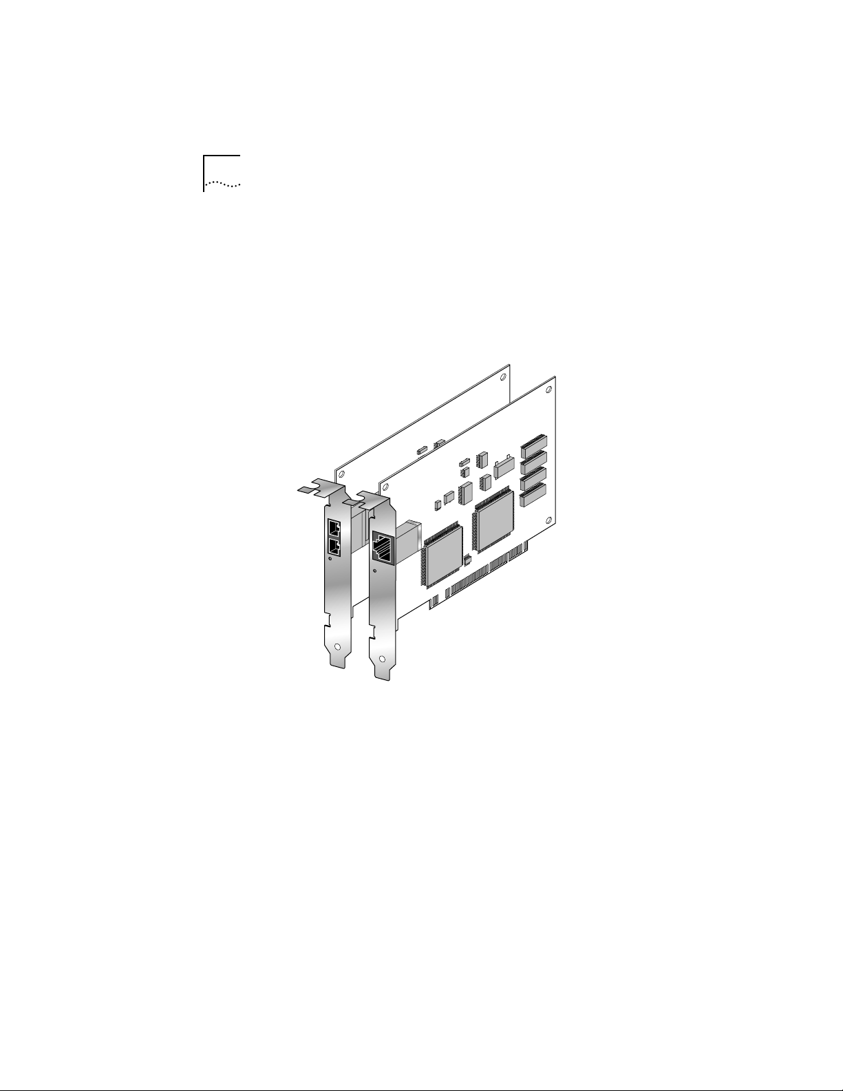
The 3Com ATMLink 3C975 NIC is available in two models:
the 3C975-F and the 3C975-UTP. The 3C975-F NIC has an
SC duplex fiber-optic cable connector for double-strand
62.5/125 µm multimode fiber-optic cable. The 3C975-UTP NIC
has an RJ-45 connector and requires Category 5 unshielded
twisted-pair cable. Both 3C975 ATMLink NICs are highperformance single-slot, bus master, half-length PCI cards that
provide 155.52 megabit per second (Mbps) SONET (STS-3c)
physical layer support.
The 3C975 ATMLink NICs support the following features:
®
3C975 ATMLink™ 155 PCI network interface
■ ATM Forum standard LAN Emulation Client (LEC)
■ ATM Forum AAL5 ATM adaptation layer
■ ATM Forum UNI 3.0/3.1 standard signaling for switched
virtual circuit (SVC) connections
■ Up to 4 NICs per system
■ Up to 16 emulated LANs (ELANs) per NIC
■ Up to 512 active connections per NIC
■ Up to 4,096 open and 1,024 simultaneously active virtual
channel connections per system
■ Resilient Server Link capability to protect against link failure
■ Compliance with PCI Local Bus Specification, revision 2.0
■ Link LED to indicate connection status
Page 16
1-2 CHAPTER 1: INTRODUCTION
■ Traffic shaping (user-defined maximum peak rate per ELAN)
■ Interim Local Management Interface (ILMI) 3.0 service
■ User-selectable virtual path identifier/virtual circuit identifier
(VPI/VCI) range
■ Simple Network Management Protocol (SNMP) agent for NICs
operating under the Windows NT
®
operating system
ATM
LINK
ATM
LINK
3C975-F
3C975-UTP
Figure 1-1 3C975-F and 3C975-UTP ATMLink NICs
Page 17

Emulated LAN (ELAN) Overview 1-3
Emulated LAN (ELAN) Overview
The 3Com ATMLink network driver conforms to the
ATM Forum LAN Emulation over ATM Specification 1.0 to
interoperate with legacy LAN networks. LAN emulation
supports the multicast, broadcast, and address resolution
services characteristic of shared media LANs, within the
connection-oriented ATM environment. Four devices are
defined to provide these LAN emulation services:
■ LAN Emulation Client (LEC) found on all end stations
■ LAN Emulation Configuration Server (LECS)
■ LAN Emulation Server (LES)
■ Broadcast and Unknown Server (BUS)
The 3C975 ATMLink NIC network driver provides the LAN
Emulation Client and supports up to 16 LECs per NIC. Each LEC
configured on an ATMLink NIC is regarded by the network
operating system as a separate (emulated) NIC and receives a
unique MAC address. An “emulated” NIC connects to an
emulated LAN (ELAN). In short, each physical ATMLink NIC can
connect to up to 16 separate ELANs.
The term ELAN is often used to denote an LEC in the 3Com
ATMLink utilities, installation programs, and user guide.
An ELAN is a logical grouping of end stations within an ATM
network. The ATM network administrator creates ELANs when
configuring the ATM switches. Membership in an ELAN is
independent of the physical location of the end station within
the ATM network. An end station can belong to multiple
ELANs simultaneously. Mixed-media edge devices (such as the
®
3Com LinkSwitch
2700 switch) that are connected to ATM
switches enable ATM end stations to interoperate with legacy
LAN end stations, because the legacy LAN end station and the
ATM end station can be members of the same ELAN. This
guide includes configuration procedures that allow an LEC to
join an ELAN.
Page 18

1-4 CHAPTER 1: INTRODUCTION
For more detailed information on LAN emulation and
emulated LANs, access the Networking Solutions Center on
the 3Com World Wide Web site at www.3com.com. White
papers on ATM are found in the Advanced Technology
Solutions section.
Software Descriptions
The following software is contained on the ATMDisk™ diskettes
shipped with the 3C975 ATMLink NIC.
■ Network driver for Microsoft
and 4.0
■ Network driver and NetWare
®
NetWare server, versions 4.x and 3.12
Novell
■ ATMLink diagnostic utility (DOS version)
■ ATMLink utility (Windows NT and NetWare versions)
Network drivers and utility programs are periodically updated
and made available through 3Com online services. See
Appendix B for details on how to use 3Com online services.
®
Windows NT, versions 3.51
®
Loadable Modules (NLMs) for
Network Driver Description
3Com ATMLink network drivers support the following
features:
■ Simultaneous operation of up to four physical NICs per system
■ ATM Forum LEC, version 1.0 for token ring and Ethernet LANs
■ ATM Forum UNI 3.0 and 3.1 signaling
■ 16 ELANs per NIC
■ ILMI 3.0 services
■ Resilient server links (RSL)
■ Traffic shaping
■ SNMP agent for NICs operating under Windows NT
Page 19

Software Descriptions 1-5
The NetWare 4.x and 3.12 drivers and Windows NT network
drivers support up to four physical NICs per system.
Each physical NIC can be configured to support up to 16 LECs.
Each LEC operates as a virtual NIC and has a unique MAC
address.
Only one LEC per NIC is supported in NetWare 3.12.
The ATMLink NIC network driver uses switched virtual circuits
(SVCs) to establish network connections with up to 4,096
open virtual channel connections (VCCs) supported per
system. Each LEC requires a minimum of four VCCs in addition
to those needed for its data requirements. These four VCCs are
used by the LAN Emulation Server (LES) and the Broadcast
and Unknown Server (BUS).
Resilient server links allow the network administrator to
designate up to three of the installed 3C975 ATMLink NICs as
standby NICs. In the event of link failure, the standby NIC
assumes the configuration profile and network traffic of a
failed active ATMLink NIC. Resilient server links are discussed
in Chapter 3 and Chapter 4.
The ATMLink network drivers let the ATM network
administrator set a maximum peak cell rate value for each
LEC. This form of bandwidth allocation is useful in mitigating
congestion and ensuring optimum usage of bandwidth.
Diagnostic Utility Description
The ATMLink diagnostic utility is a DOS program that tests the
internal integrity of the 3C975 ATMLink NIC and its ability to
send and receive packets. The diagnostic utility also identifies
the MAC address, the PCI slot number, and manufacturer’s
information for each installed 3Com ATMLink NIC. It is
recommended that you run the diagnostic utility after
installing the ATMLink NIC and before installing the network
drivers. For information on how to use the diagnostic utility,
see Chapter 6, “Diagnostics and Troubleshooting.”
Page 20

1-6 CHAPTER 1: INTRODUCTION
ATMLink Utility Description
An ATMLink utility for Microsoft Windows NT and for
Novell NetWare is shipped on the ATMDisk diskettes. Use the
ATMLink utility to display configuration and operating status
of all installed ATMLink NICs and ELANs, as well as to reset a
NIC. Chapter 5 describes how to use the ATMLink utility.
Page 21

2
HARDWARE INSTALLATION
This chapter describes the procedure for installing the
3C975 ATMLink NIC in your PCI-bus computer system. Follow
all applicable instructions included with your system
documentation on PCI-bus installations.
Installation Overview
Hardware installation consists of the following major steps:
■ Unpacking the 3C975 ATMLink NIC
■ Installing the 3C975 ATMLink NIC in an available PCI slot
■ Connecting the appropriate cables
Please observe all special notes and precautions.
For technical specifications on the 3C975 ATMLink NIC, see
Appendix A.
Installing the 3C975 ATMLink NIC
To install the 3C975 ATMLink NIC in your computer, perform
these steps.
Keep the 3C975 ATMLink NIC in the protective antistatic bag
until you are ready to install it. To prevent damage to the NIC
due to electrostatic discharge, wear a grounding strap and
handle the NIC by its edges only. If you do not have a
grounding strap, touch the chassis or the power supply just
before handling the NIC. Do not touch the components or
any metal parts on the NIC, except for the backplate.
1 Unpack and inspect the 3C975 ATMLink NIC for damage.
2 Exit all open applications and user processes.
Page 22
2-2 CHAPTER 2: HARDWARE INSTALLATION
3 Turn off the power to the computer system and any
attached devices.
4 Unplug the power cables from the power supply.
WARNING: Your computer operates with voltages that can be
lethal. Before you remove the computer cover, carefully review
the steps in this procedure and observe all cautions and
warnings to protect yourself and to prevent damage to the
computer.
5 Remove the cover from your computer.
6 Locate an empty bus master PCI-bus expansion slot.
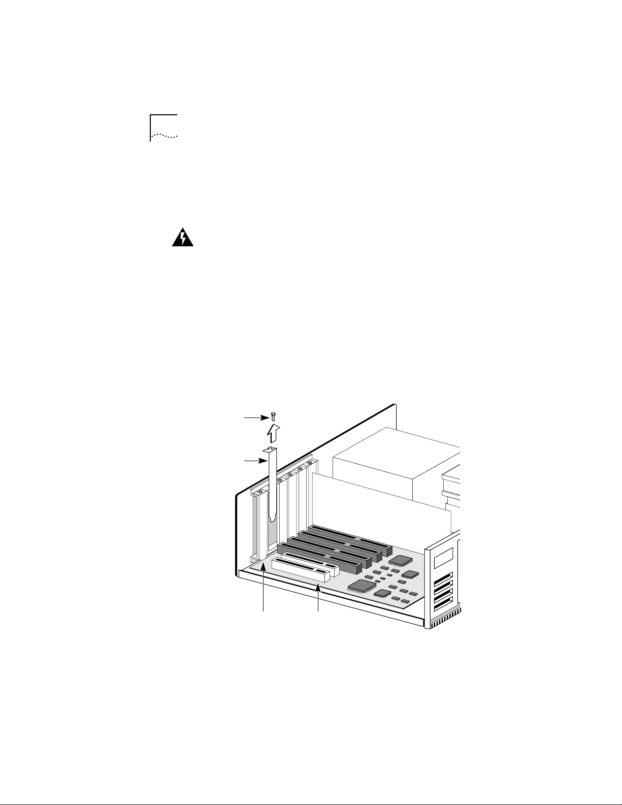
7 Remove the metal expansion slot cover from the
computer chassis, as shown in Figure 2-1.
Save the screw for step 11 later in this section.
Mounting
screw
Expansion
slot cover
Expansion
slots
Figure 2-1 Removing the Expansion Slot Cover
32-bit PCI
slots
Page 23
Installing the 3C975 ATMLink NIC 2-3
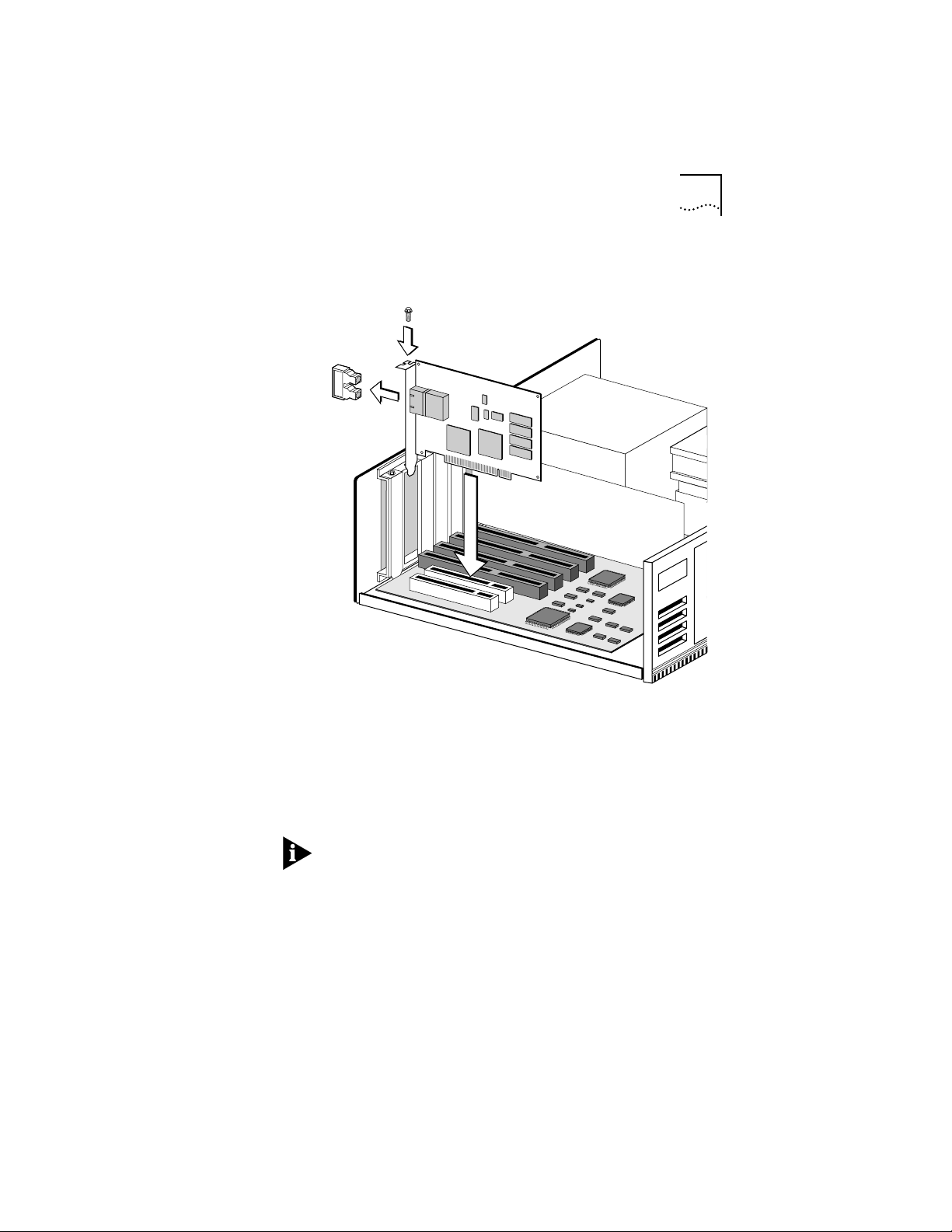
8 Insert the 3C975 ATMLink NIC in the selected slot, as
shown in Figure 2-2.
Figure 2-2 3C975-F ATMLink NIC Installed in the Chassis
9 Write down the MAC address of the NIC and note which
slot you used.
This information is helpful when installing the network
drivers and connecting the cables to the ATM switch.
The MAC address is the 12-digit hexadecimal number printed
on the small bar code label on the component side of the NIC.
10 Press down gently and firmly on the NIC to seat it properly.
11 Use the screw removed in step 7 to secure the
3C975 ATMLink NIC bracket to the system chassis.
12 Replace the system cover.
Page 24
2-4 CHAPTER 2: HARDWARE INSTALLATION
13 Connect the power cables and turn on the power to the
computer.
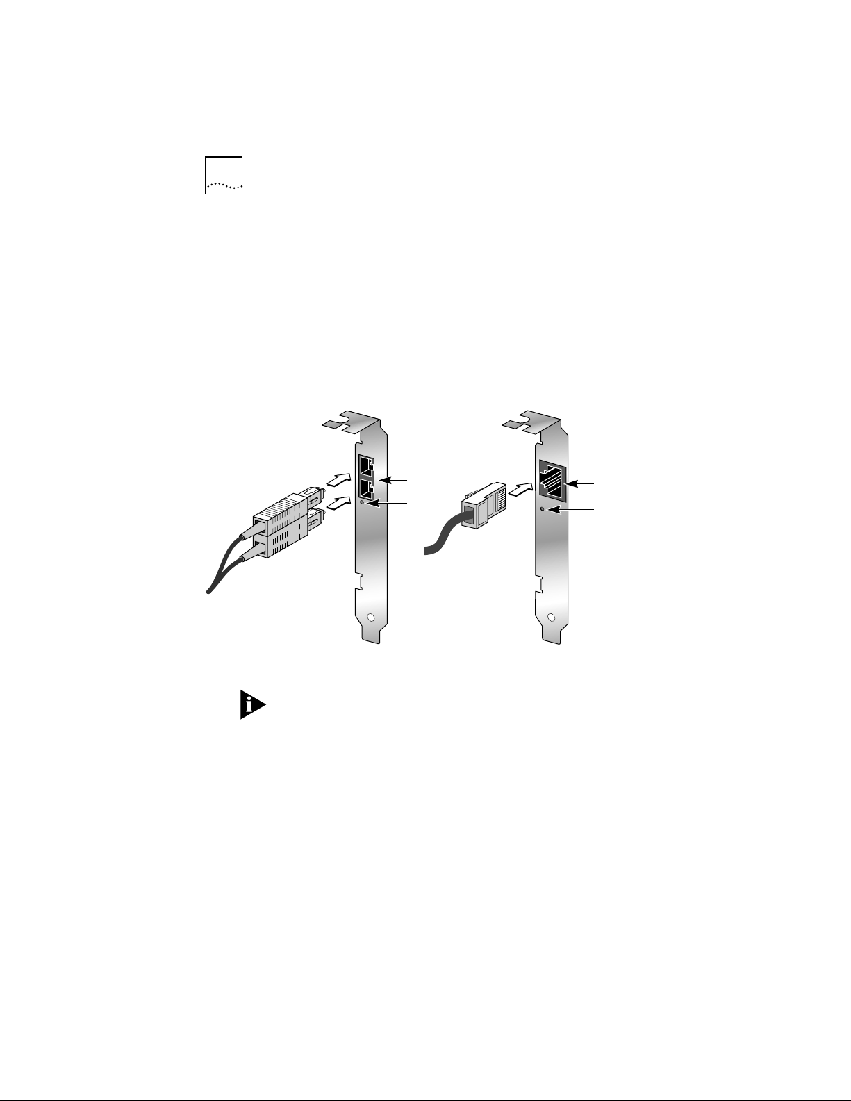
14 Connect the 3C975 ATMLink NIC to the network.
The 3C975-F NIC uses 62.5/125 µm multimode fiber-optic
cable with SC duplex connectors. The 3C975-UTP NIC uses
Category 5 unshielded twisted-pair cable with an RJ-45
connector. Both models are shown in Figure 2-3.
The physical installation of the ATMLink NIC is now complete.
ATM
SC connector
port
LINK
Figure 2-3 SC Duplex and RJ-45 Connectors
LED
ATM
LINK
RJ-45
port
LED
It is strongly recommended that you run the ATMLink
diagnostic utility before attempting to install the network
drivers. The diagnostic utility verifies that the on-board
components of each NIC function correctly. This utility also
correlates the MAC address of the NIC with its PCI slot number.
You must know the PCI slot number to load, configure, or
reconfigure the Microsoft Windows NT network drivers.
The next step is to install the network software driver. For
server driver installation procedures, refer to Chapter 3 for
Windows NT, or to Chapter 4 for Novell NetWare.
Page 25

3
WINDOWS NT DRIVER
INSTALLATION
The 3C975 ATMLink NIC driver for file servers running
Windows NT provides standards-based ATM LAN emulation
connectivity to an ATM network. This permits legacy LAN
networking technologies and protocols (such as Ethernet
and token ring) to run over an ATM network.
This chapter includes procedures to install and remove the
3C975 ATMLink Windows NT network driver, as well as
information about ELAN configuration and resilient links.
A basic knowledge of Windows NT server operations and
ATM concepts is required.
The term ELAN is often used to denote an LEC in the graphical
user interface and in the following procedures.
Driver Installation Overview
The Windows NT driver installation program consists of two
parts:
■ NIC detection, creation of resilient server links, and ELAN
allocation
■ NIC and ELAN configuration
During NIC detection the user designates each detected 3Com
3C975 ATMLink NIC as either an active or a standby NIC (see the
section “Resilient Server Links Overview” later in this chapter)
and specifies the number of ELANs supported by each active
NIC. In the NIC/ELAN configuration portion of the driver
installation, the user sets the ATM parameters for all active NICs
and ELANs as well as configuration information for standby NICs.
There can be up to four 3Com 3C975 ATMLink NICs installed
in a single computer system, with each NIC supporting up to
16 ELANs.
Page 26

3-2 CHAPTER 3: WINDOWS NT DRIVER INSTALLATION
Driver Installation Requirements
Please confirm that the following requirements are met before
you install and configure the 3Com ATMLink NIC Windows NT
network driver.
Hardware Requirements
■ Computer with Intel®-based CPU and bus master PCI bus,
running Microsoft Windows NT version 3.51 or 4.x
■ 3.5-inch floppy disk drive
■ At least one 3Com ATMLink NIC installed in the system
Memory Requirements
Use the following formula to determine the Windows NT
memory requirements in megabytes of RAM:
(16 x Frame_Size) + [(No. of NICs –1) x (No. of ELANS)]
where:
Frame_size = 1 When the maximum frame size is 1514 bytes
Frame_size = 2 When the maximum frame size is 4542 bytes
Frame_size = 4 When the maximum frame size is 9232 bytes
No. of NICs = The number of ATMLink NICs installed in the
computer
No. of ELANs = The number of ELANs on the NIC with the
most ELANs
When NICs with different maximum frame sizes are installed in
the same computer, use the larger Frame_Size value.
Round up the result to the first integral multiple of 8.
Most Ethernet ELANs use a maximum frame size of 1514 bytes.
Token ring ELANs typically use a maximum frame size of 4542
or 9232 bytes. See Table 3-1 for more information on the
Maximum Frame Size configuration parameter.
Page 27

Driver Installation Requirements 3-3
Memory Requirement Scenario 1
There are two NICs installed. One has a maximum frame size
of 1514 bytes and four ELANs, and the other is a standby NIC.
The memory requirement is 24 megabytes of RAM.
Frame_Size = 1 (1514 bytes maximum frame size)
No. of NICs = 2 (two NICs are installed in the computer)
No. of ELANs = 4 (only one NIC has ELANs configured)
(16 × 1) + [(2 – 1) × (4)] = 20
The closest integral multiple of 8 greater than 20 is 24.
Memory Requirement Scenario 2
There are three NICs installed. One is a token ring LAN type
with a maximum frame size of 4542 and four ELANs, one is a
token ring LAN type with a maximum frame size of 9232 and
two ELANs, and one is an Ethernet LAN type with a maximum
frame size of 1514 and six ELANs. The memory requirement is
80 megabytes of RAM.
Frame_Size = 4 (use the largest value of all present)
No. of NICs = 3 (three NICs are installed in the computer)
No. of ELANs = 6 (the maximum number of ELANs on any one NIC)
(16 × 4) + [(3 – 1) × (6)] = 76
The closest integral multiple of 8 greater than 76 is 80.
Software Requirements
■ ATMDisk diskette for Windows NT
3Com strongly recommends that your Windows NT operating
system be updated with the most recent service packs available
from Microsoft technical support (www.microsoft.com).
Page 28

3-4 CHAPTER 3: WINDOWS NT DRIVER INSTALLATION
NIC Information Requirements
■ Names of the ELANs to be configured on each ATMLink NIC
■ IP address and subnet mask of each ELAN using TCP/IP if a
DHCP server is not being used
■ ATM address of the LES or LECS (other than the ATM Forum
Well-known Address) if ILMI services are not used
■ PCI slot number of each installed ATMLink NIC
The MAC address and PCI slot numbers of installed 3Com
ATMLink NICs are used in the Windows NT driver installation.
They can be obtained by using the diagnostic utility (see
Chapter 6 for details).
Resilient Server Links Overview
Resilient server links add redundant function to your server
to protect against network disruption and data loss.
To use resilient links, you must install two or more 3Com
ATMLink NICs in your system. During the network driver
configuration procedure, at least one NIC must be designated
an active NIC. The standby NIC takes over when the link on a
designated active NIC port is lost.
Rules for Using Resilient Server Links
■ Resilient server links are established only among ATMLink NICs
installed in the same computer.
■ To make a resilient server link, at least two ATMLink NICs must
be installed in the same computer, and one of the NICs must
be an active NIC.
■ Active NICs and their standby NICs must be connected to
switches on the same ATM network.
■ Up to three standby NICs can be assigned to a single active NIC.
■ A single standby NIC can be assigned to as many as three
active NICs.
Page 29

Driver Installation Summary for Experienced Users 3-5
■ In a two-NIC scenario, when NIC 1 is active and NIC 2 is standby,
and if the link on the NIC 1 port fails, NIC 2 assumes the
configuration profile of NIC 1 and becomes the active NIC.
NIC 1 now becomes a standby NIC for NIC 2.
■ When a standby NIC assigned to multiple active NICs becomes
active, it can no longer be a standby NIC for its other designated
active NICs.
■ When an active NIC with multiple standby NICs fails, the first
eligible standby NIC (in driver load order) assumes the
configuration profile of the active NIC. If this NIC in turn fails,
the next designated standby NIC (in driver load order) takes
over, and so on.
■ A NIC cannot be configured as a standby NIC for another
standby NIC.
■ A resilient server link is established only if the active NIC is
operational after Windows NT is booted.
The standby NIC cannot assume the configuration profile of
an active NIC that has never been operational.
Driver Installation Summary for Experienced Users
Experienced Windows NT users knowledgeable in ATM
configuration can use the following summary to install the
3C975 ATMLink network driver for Windows NT. Other users
should proceed to the section “Installing the Network Driver”
later in this chapter.
Before You Begin
■ Verify that all system and memory requirements are met.
■ When multiple ATMLink NICs are installed, run the
ATMLink diagnostic utility.
Write down the MAC address, the bus number, and the slot
number of each installed ATMLink NIC. See Chapter 6 for
information on the ATMLink diagnostic utility.
Page 30

3-6 CHAPTER 3: WINDOWS NT DRIVER INSTALLATION
■ Obtain the names of the ELANs you wish to join from your
ATM system administrator.
■ Obtain an IP address for each ELAN you intend to install, if the
ELANs are to be used on an IP network without a DHCP server.
Part One: NIC Detection, Resilient Server Links, and
ELAN Allocation
1 From the Network Settings window in the Control Panel,
click Add Adapter and copy the 3C975 NIC driver from the
3Com ATMDisk diskette.
The NIC Installation dialog box appears, identifying the first
3Com ATMLink NIC found on the PCI bus.
2 Click Yes to install the ATMLink NIC network driver on the
identified NIC, or click No to bypass the NIC.
You may wish to bypass a previously installed NIC in the system.
The NIC Mode dialog box appears.
3 Make the identified NIC an active or a standby NIC.
■ If you select Stand-by, the NIC Installation dialog box
reappears when there are multiple NICs installed.
■ If you select Active, the Total Number of ELANs dialog box
appears.
4 Enter the number of ELANs to be supported by the
identified NIC.
If more than one 3Com ATMLink NIC is installed, the
installation program returns to step 2 and the NIC Installation
dialog box.
Page 31

Driver Installation Summary for Experienced Users 3-7
Part Two: NIC and ELAN Configuration
After all the 3Com ATMLink NICs have been detected, the
driver files copied, and the number of ELANs specified, the
3Com ATMLink Installation window appears.
1 For each installed 3Com ATMLink NIC, set the following
global NIC parameters (these are the same for all NICs in
the system):
■ VPI/VCI Range
■ Signaling Version
2 For each installed 3Com ATMLink NIC, set the following local
NIC parameters (these can vary with each NIC in the system):
■ LAN Type
■ ILMI VPI/VCI
■ Maximum Frame Size
■ Resilient Server Links
All of the above parameters except resilient link assignments
must match the ATM switch settings. The default values work
for most installations.
3 For each ELAN, set the following parameters:
■ ELAN Name
■ Peak Rate
■ LE Configuration Mode
4 Click Save & Exit in the 3Com ATMLink Installation window.
5 Click OK in the Network Settings window.
6 Configure the IP parameters for each ELAN if IP is used.
Enter dummy IP values for each standby NIC.
7 Restart Microsoft Windows NT.
Page 32

3-8 CHAPTER 3: WINDOWS NT DRIVER INSTALLATION
You have completed the ATMLink Windows NT network driver
installation. The remaining sections of this chapter provide a
more detailed approach to installing the ATMLink NIC network
driver with Windows NT.
Installing the Network Driver
The following driver installation procedure is standard to
Windows NT 3.51. The driver can also be installed as part of
the Custom setup procedure supplied with your Windows NT
operating system. Refer to the Microsoft Windows NT
System Guide for additional information.
NIC Detection, Resilient Server Links, and ELAN Allocation
It is assumed that at least one 3C975 ATMLink NIC is installed
in the system PCI bus.
1 Boot your system under Windows NT.
2 Log into your Windows NT Administrator account.
3 Double-click the Control Panel icon.
4 Double-click the Network icon.
The Network Settings window shown in Figure 3-1 appears.
5 Click Add Adapter.
The Add Network Adapter window appears, as shown in
Figure 3-2.
6 Select <Other>Requires disk from manufacturer from the
bottom of the Network Adapter Card list box.
7 Click Continue.
The Insert Disk dialog box appears, as shown in Figure 3-3.
Page 33

Installing the Network Driver 3-9
Figure 3-1 Network Settings Window
Figure 3-2 Add Network Adapter
Figure 3-3 Insert Disk Dialog Box
Page 34

3-10 CHAPTER 3: WINDOWS NT DRIVER INSTALLATION
8 Insert the ATMDisk diskette for Windows NT in a floppy
disk drive.
If necessary, change the drive designation to the appropriate
floppy drive.
9 Click OK.
The Select OEM Option window appears, as shown in
Figure 3-4.
Figure 3-4 Select OEM Option Window
10 Select 3Com ATMLink PCI NIC (3C975) and click OK.
The installation program copies the network driver, ATM utility,
ATM diagnostic utility, and SNMP agent files to the system hard
disk and then detects all installed 3Com ATMLink NICs in the
system. The dialog box shown in Figure 3-5 appears.
Figure 3-5 NIC Installation Dialog Box
Page 35

Installing the Network Driver 3-11
11 Click Yes if you want the 3Com driver installed on the
indicated NIC. Otherwise, click No.
If you click Yes , the NIC Mode dialog box appears, as shown in
Figure 3-6. If you click No, the NIC Installation dialog box
reappears for the next discovered ATMLink NIC.
To correlate the PCI bus and slot number with a physical NIC,
run the 3Com ATMLink diagnostic utility.
Figure 3-6 NIC Mode Dialog Box
12 Click Active to make the identified NIC an active NIC, or click
Stand-by to make it a standby NIC (resilient server link).
■ If you select Stand-by, the NIC Installation dialog box
reappears for the next discovered 3C975 ATMLink NIC.
■ If you select Active, the Total Number of ELANs dialog box
appears, as shown in Figure 3-7.
Figure 3-7 Total Number of ELANs Dialog Box
13 Enter the number of ELANs you require on the indicated
NIC, and click OK.
The maximum number of ELANs per NIC is 16.
Page 36

3-12 CHAPTER 3: WINDOWS NT DRIVER INSTALLATION
Each ELAN on a physical NIC is assigned a unique MAC
address that is an increment of the base MAC address of
the physical NIC.
When you have completed resilient server link and ELAN
assignments for each discovered NIC, the 3Com ATMLink
Installation window appears, as shown in Figure 3-8 in the
next section.
NIC and ELAN Configuration
The ELANs allocated to an active NIC appear in the ELAN portion
of the ATMLink Installation window (Figure 3-8). The MAC
addresses of the ELANs do not appear until the system is
rebooted. The VCI/VPI Range and Signaling are global
parameters set the same for all NICs in the system. LAN Type,
ILMI VPI/VCI, and Maximum Frame Size are local NIC parameters
and can be different for each NIC. Traffic Shaping and LE
Configuration Mode, shown in Figure 3-9, are ELAN-specific
parameters that can be different for each ELAN.
Figure 3-8 3Com ATMLink Installation Window
Page 37

Installing the Network Driver 3-13
Table 3-1 describes the fields and buttons in the ATMLink
Installation and ELAN Configuration windows. Default values
are shown in bold.
Table 3-1 3C975 ATMLink NIC Installation Configuration Parameters
Range of Values
Field
ATMLink NIC All ATMLink NICs with
Global NIC Parameters (must be the same for all NICs in a computer system)
VPI/VCI Range 0 bits/12 bits
Signaling UNI v3.0
Local NIC Parameters (specific to each NIC in a computer system)
LAN Type Ethernet (802.3)
ILMI VPI 0 This parameter is determined by the
ILMI VCI 16 This parameter is determined by the
Maximum Frame Size 1514
Resilient Server Link Any active NIC Select one or more eligible active NICs
(continued)
(Defaults in Bold)
installed drivers by PCI
slot, bus number, and
MAC address (after
initial installation)
1 bits/11 bits
2 bits/10 bits
8 bits/4 bits
UNI v3.1
Token Ring (802.5)
4542
9232
Description
Select the NIC you wish to configure
from the drop-down list.
This parameter is determined by the
ATM switch setting.
This parameter is determined by the
ATM switch setting.
All ELANs configured on a NIC must be
the same LAN type.
ATM switch setting.
ATM switch setting.
All ELANs on the same NIC have the
same MFS value, also called maximum
transfer unit (MTU). Use 1514 for
Ethernet, 4542 for 4 Mbps token ring,
and 9232 for 16 Mbps token ring.
Only end stations using the same value
can interoperate.
to make the current ATMLink NIC a
standby NIC.
Page 38

3-14 CHAPTER 3: WINDOWS NT DRIVER INSTALLATION
Table 3-1 3C975 ATMLink NIC Installation Configuration Parameters (continued)
Range of Values
Field
ELAN Parameters (specific to each ELAN)
ELAN Name 0- to 32-character
Traffic Shaping 1–155 Mbps Sets the maximum bandwidth available
LE Configuration
Mode
(Defaults in Bold)
ASCII string
Automatic using
ILMI
Description
ELAN names must match ELAN names
configured on the ATM switch. ELAN
names are case-sensitive.
to an ELAN.
Select Automatic using ILMI for ILMI
service.
Automatic with
specific LECS
Manual with specific
LES
LECS ATM Address ATM Forum
Well-known Address
LES ATM Address No default Enter the 20-byte network address of
Select Automatic with specific LECS to
connect with a LECS different from that
specified by ILMI.
Select Manual with a specific LES to
bypass the LECS and connect directly
with a LES of known address.
Enter the 20-byte network address of
the target LECS if it does not use the
ATM Forum Well-known Address.
the target LES.
To configure NICs and ELANs, follow these steps:
1 Select the NIC that you want to configure from the
ATMLink NIC list box in the ATMLink Installation window.
You can configure the NICs in any order that you wish.
2 To make the selected NIC a standby NIC, select one or
more active NICs.
Eligible active NICs appear in the Resilient Server Link box.
If you make a NIC a standby NIC, no further configuration is
necessary. Proceed to step 7.
Page 39

Installing the Network Driver 3-15
3 Change the global NIC parameters if necessary.
Global parameters values are the same for every NIC in the
computer system.
a Select a VPI/VCI range.
Select the VPI/VCI range that matches the VPI/VCI range
set on the ATM switch by the ATM network administrator.
The default is 0 bits VPI, 12 bits VCI.
b Select a signaling option.
Select the option that matches the signaling option set
on the ATM switch by the ATM network administrator.
The default is UNI version 3.1.
4 Change the local NIC parameters if necessary.
Local parameter values are specific to the NIC being configured.
a Select a LAN type for the NIC.
All ELANs allocated to this NIC will be of this same LAN
type. The default value is Ethernet.
b Set the maximum frame size (also known as the
maximum transfer unit [MTU]). Select 1514 for Ethernet,
4542 for 4 Mbps token ring, or 9232 for 16 Mbps token
ring. The same maximum frame size value should be used
by all end stations on the same network.
c Edit the ILMI VPI/VCI parameters if necessary.
The ILMI VPI/VCI is set on the ATM switch. Most
implementations of ILMI use the default value of VPI 0
and VCI 16.
Page 40

3-16 CHAPTER 3: WINDOWS NT DRIVER INSTALLATION
5 Select an ELAN name and then click Configure ELAN.
The ELAN Configuration window appears, as shown in
Figure 3-9.
Figure 3-9 ELAN Configuration Window
a Enter the ELAN name.
The ELAN names should match the ELAN names configured
on the ATM switch, LECS, or LES. In many ATM installations
the ELAN name is supplied by the LES.
b Select the LE configuration mode.
■ Select Automatic using ILMI to use the ATM switch-based
Interim Local Management Interface service (ILMI) to
connect to the LES.
■ Select Automatic with specific LECS if you wish to contact
an LECS not identified by ILMI. Enter the 20-byte ATM
address of the specific LECS if it does not use the default
ATM Forum Well-known Address. To reinstate the default
value, click the Well-known LECS Address button.
■ Select Manual with specific LES to connect directly to the
LES. Enter the 20-byte ATM address of the LES.
Page 41

Installing the Network Driver 3-17
6 When all the clients are configured, click OK.
The 3Com ATMLink Installation window shown in Figure 3-8
reappears.
All entries and edits to the 3Com ATMLink Installation and
ELAN Configuration windows are saved only when you select the
Save & Exit button in the 3Com ATMLink Installation window.
Clicking Cancel erases all entries and edits in both windows.
7 Click Save & Exit to exit the 3Com ATMLink Installation
window.
8 Click OK in the Network Settings window.
If IP services are installed, the TCP/IP Configuration dialog box
appears, as shown in Figure 3-10. If any of the ELANs and
standby NICs are on IP networks, proceed to the next step;
otherwise, click Cancel in the TCP/IP Configuration dialog
box and proceed to step 11.
Figure 3-10 TCP/IP Configuration Window with Sample Entries
Page 42

3-18 CHAPTER 3: WINDOWS NT DRIVER INSTALLATION
9 Edit the TCP/IP parameters.
All ELANs and standby NICs using TCP/IP require a unique IP
address and subnet mask. Enter dummy values for the
standby NICs.
Contact your network administrator for appropriate IP
addresses and subnet masks. Be sure that dummy IP addresses
used for standby NICs do not conflict with other addresses on
the network.
Each ELAN must be on a different subnet. Refer to the
Microsoft Windows NT System Guide for information on the
other TCP/IP configuration values.
a Select an ELAN or standby NIC from the Adapter list box.
You can configure the ELANs and NICs in any order.
b Enter the IP address for an ELAN or a dummy address for a
standby NIC.
c Enter the subnet mask.
d Enter the default gateway if applicable.
If your local network has a gateway to other networks,
you must enter your network’s gateway address to
communicate with nodes on the other side of the
gateway.
e Enter the primary WINS server if applicable.
This is the address of the primary name server used for
looking up host names belonging to the local and
connected networks.
f Enter the secondary WINS server if applicable.
If the primary name server does not respond to requests
for host information, the secondary server will be queried.
g Repeat substeps a through f for each ELAN.
Page 43

Verifying Driver Installation and Configuration 3-19
10 Click OK when the TCP/IP configuration is complete.
The restart prompt shown in Figure 3-11 appears.
Figure 3-11 Restart Prompt for Adapter Driver
11 Make sure that all cables are connected to the appropriate
switch ports.
12 Select Restart Now to restart the Windows NT system.
This completes the installation and configuration of the
3Com ATMLink Windows NT network driver.
Verifying Driver Installation and Configuration
Perform the following procedures to verify that the driver is
installed and operative:
■ If you are using TCP/IP, ping the ATMLink end station that you
want to test.
■ Check the link LED.
The LED is lit when the driver is loaded and a good connection
is made to the ATM switch. The LED on a standby NIC does not
light unless the NIC changes to active status.
■ Launch the ATMLink utility and check the State parameter in
the ELAN Information window. A functional ELAN is
designated as OPERATIONAL.
■ Check the Windows NT events log for any messages about
the newly configured ELANs and NICs.
Page 44

3-20 CHAPTER 3: WINDOWS NT DRIVER INSTALLATION
Enabling and Disabling ELANs
To disable an ELAN, click the ELAN name in the 3Com ATMLink
Installation window (Figure 3-15), and then click Disable ELAN.
This action disables the protocol bindings of the ELAN. The
button name then changes to Enable ELAN.
To enable an ELAN, click the name of a disabled ELAN and
then click Enable ELAN.
Removing an ELAN
Individual ELANs are removed one at a time.
To remove an ELAN and its associated software drivers from
Windows NT, follow these steps:
1 Double-click the Control Panel icon in the Main group.
The Control Panel window appears.
2 Double-click the Network icon to access the Network Settings
window.
3 Select an ELAN from the Installed Adapter Cards list.
4 Click Remove.
You are prompted to confirm the removal of the component.
5 Click Yes to remove the ELAN.
The request is processed and the Networks Settings window
reappears.
CAUTION: Do not attempt to reinstall the ELAN before
restarting the computer.
6 Click OK in the Network Settings window.
The restart prompt appears.
7 Select Restart Now to reboot the computer.
Page 45

Adding ELANs
Additional ELANs can be added to a NIC after the initial
installation. Perform the following procedure to add
additional ELANs:
1 If multiple ATMLink NICs are installed, identify the PCI slot
and bus number of the NICs on which you want to install
additional ELANs.
Use the diagnostic utility to obtain this information if you do
not already have it.
2 Perform steps 1 through 9 of the Windows NT driver
installation procedure, as described in the section
“Installing the Network Driver.”
3 In the Select OEM Option window, select 3Com ATMLink
PCI NIC ELAN Instance, as shown in Figure 3-12.
Adding ELANs 3-21
Figure 3-12 Select OEM Option Window
Page 46

3-22 CHAPTER 3: WINDOWS NT DRIVER INSTALLATION
The installation program finds all installed 3Com ATMLink NICs.
A dialog box appears for the first NIC discovered, as shown in
Figure 3-13.
Figure 3-13 NIC Installation Dialog Box
4 If you want to add ELANs to the NIC identified in the dialog
box, click Yes ; otherwise, click No.
When you click No, and if multiple NICs are installed, the NIC
Installation dialog box reappears with the next detected NIC.
When you click Yes, the Total Number of ELANs dialog box
appears, as shown in Figure 3-14.
Figure 3-14 Total Number of ELANs Dialog Box
5 Enter the total number of ELANs you want to install on the
indicated physical NIC and click OK.
The total number of ELANs already configured on the indicated
NIC is displayed in the Total ELANs field. To add ELANs to the
NIC, enter a number that is the sum of the number of ELANs
already configured and the number of ELANs you want to add.
For example, if the NIC already has 4 ELANs and you want to
add 1 more, enter 5 in the Total ELANs field.
Page 47

Adding ELANs 3-23
The preexisting ELANs retain all of their configuration
information. The new ELANs appear in the ELAN portion of the
3Com ATMLink Installation window, as shown in Figure 3-15.
Figure 3-15 3Com ATMLink Installation Window Showing Additional
ELANs
6 Configure the new ELANs, and then click Save & Exit.
7 Click OK in the Networks Setting window.
8 Configure IP information for the new ELANs if IP is used,
and click OK; otherwise, click Cancel.
9 Restart Windows NT.
Page 48

3-24 CHAPTER 3: WINDOWS NT DRIVER INSTALLATION
Adding SNMP Support
The SNMP agent shipped with the ATMLink NIC offers limited
support for the ATM Forum LAN Emulation Client Management
Version 1.0 Specification. The agent is shipped on the
AT MD is k diskette as the LECMIB.DLL and LECIFMIB.DLL files, for
use with Windows NT only. The files are automatically copied
to the system hard drive during driver installation and install
themselves if Windows NT is running the SNMP service. If the
SNMP service was not running when the agent was copied
from the ATMD is k diskette, the agent must be manually
installed.
The ATMLink SNMP agent responds to requests from any
standard SNMP network management software. The SNMP
Get and GetNext commands work for all the LEC MIB objects.
The Set command does not work with all SNMP variables,
and the user cannot create or modify an LEC.
To manually install the ATMLink SNMP agent on your
Windows NT system, perform the following procedure:
Make sure that the SNMP service is installed on Windows NT.
See your Microsoft WIndows NT Installation Guide for more
information.
1 Perform steps 1 through 9 of the Windows NT driver
installation procedure described in the section “Installing
the Network Driver.”
2 From the Select OEM Option dialog box, select
3Com ATMLink SNMP LEC MIB Agent, as shown in Figure 3-16.
Page 49

Adding SNMP Support 3-25
Figure 3-16 Selecting the SNMP LEC MIB Agent
3 Click OK.
The SNMP agent files are copied to the system hard disk.
4 Click OK in the Network Settings window.
5 Restart Windows NT.
Page 50

4
NETWARE SERVER DRIVER
INSTALLATION
The 3C975 ATMLink NIC driver for file servers running Novell
NetWare 3.12 and 4.x provides standards-based ATM LAN
emulation connectivity to an ATM network. This permits
legacy LAN networking technologies and protocols (such as
Ethernet and token ring) to run over an ATM network.
This chapter includes procedures to install and remove the
3C975 ATMLink Novell NetWare network driver, as well as
information about LEC configuration and resilient server
links. A knowledge of Novell NetWare and ATM is required.
If the information in the release notes shipped with your
product or the README.TXT files on the ATMDisk diskette
differs from the information in this guide, follow the release
notes or README.TXT files.
Driver Installation Overview
Installation of the 3Com ATMLink NIC NetWare driver is
divided into three parts:
■ Confirming that the driver installation requirements have
been met
■ Copying the driver to the hard drive of the server manually
or by using the NetWare install utility
■ Configuring the LEC parameters by editing the
AUTOEXEC.NCF file or using the NetWare install utility
The installation requirements specify the hardware and
software required for installation of the network driver.
Required software includes NetWare Loadable Modules (NLMs)
that permit NetWare versions 3.12 and 4.x to function with
the 3Com ATMLink NIC network drivers.
Page 51

4-2 CHAPTER 4: NETWARE SERVER DRIVER INSTALLATION
Copying the driver from the ATMDisk diskette to the hard
drive of the server is a standard NetWare driver installation
operation, performed manually or by using the standard
NetWare install utility. This guide documents the use of the
NetWare install utility.
After the ATMLink NIC network driver (3C975.LAN) has been
copied to the server system directory, the driver is modified
with the NetWare install utility to configure the parameters of
the first LEC. During this process the NIC can also be
configured for resilient server links. When all the LEC
parameters or resilient link parameters have been set, the
installation program saves the parameters, loads the driver,
and modifies the AUTOEXEC.NCF file by adding appropriate
load and bind command lines.
To configure additional LECs, you must modify the same
3C975.LAN driver. Resilient server links and LECs can be
configured manually by editing the AUTOEXEC.NCF file.
Procedures for manually editing the AUTOEXEC.NCF file and
for unloading network drivers are included at the end of this
chapter.
NetWare 4.x supports up to 4 3C975 ATMLink NICs per system,
with up to 16 LECs per NIC. NetWare 3.12 supports up to four
NICs per system and one LEC per NIC.
Page 52

Driver Installation Requirements 4-3
Driver Installation Requirements
Please confirm that the following installation requirements
are met before installing and configuring the network driver.
Hardware Requirements
■ File server with a PCI bus running Novell NetWare version 3.12
or 4.x
■ 3.5-inch floppy disk drive
■ At least one 3Com ATMLink NIC installed in the system
Memory Requirements
■ 64 MB of system memory recommended for each installed
ATMLink NIC
Software Requirements
■ 3Com ATMDisk diskette for Novell NetWare
Before installing the driver, review the README.TXT document
included on the ATMDisk diskette.
3Com strongly recommends that your Novell network
operating system be updated with the most recent patches
and updates available from Novell technical support
(www.novell.com).
NIC Information Requirements
■ The names of the ELANs to be configured on each ATMLink NIC
■ IP address and subnet mask of each LEC using TCP/IP
The MAC address and PCI slot numbers of installed 3Com
ATMLink NICs are not used in the NetWare driver installation,
but they can be obtained by using the diagnostic utility (see
Chapter 6 for details).
Page 53

4-4 CHAPTER 4: NETWARE SERVER DRIVER INSTALLATION
Resilient Server Links Overview
Resilient server links add redundant function to your server
to protect against network disruption and data loss.
To use resilient links, you must install two or more 3Com
ATMLink NICs in your system. During the network driver
configuration procedure, at least one NIC must be designated
as an active NIC, and one a standby. The standby NIC takes
over when the link on a designated active NIC port is lost.
Rules for Using Resilient Links
■ Resilient server links are established only among ATMLink NICs
installed in the same computer.
■ To make a resilient server link, at least two ATMLink NICs
must be installed in the same computer, and one of the NICs
must be an active NIC.
■ Active NICs and their standby NICs must be connected to
switches on the same ATM network.
■ Up to three standby NICs can be assigned to a single active NIC.
■ A single standby NIC can be assigned to as many as three
active NICs.
■ In a two-NIC scenario, when NIC 1 is active and NIC 2 is
standby, and if the link on the NIC 1 port fails, NIC 2 assumes
the configuration profile of NIC 1 and becomes the active NIC.
NIC 1 now becomes a standby NIC for NIC 2.
■ When a standby NIC assigned to multiple active NICs becomes
active, it can no longer be a standby NIC for its other
designated active NICs.
■ When an active NIC with multiple standby NICs fails, the first
eligible standby NIC (in driver load order) assumes the
configuration profile of the active NIC. If this NIC in turn fails,
the next designated standby NIC (in driver load order) takes
over, and so on.
Page 54

Resilient Server Links Overview 4-5
■ A NIC cannot be configured as a standby NIC for another
standby NIC.
■ A resilient server link is established only if the active NIC is
loaded before the standby NIC and is operational after
NetWare is booted.
The standby NIC cannot assume the configuration profile of
an active NIC that has never been operational.
Implementing Resilient Server Links in NetWare
In NetWare, an active NIC and all of its standby NICs must
share the same interrupt request level (IRQ). Because the PCI
bus often assigns different IRQs to devices found in the PCI
slots, you may need to use the system CMOS setup utility to
manually assign the same IRQ to the target NICs. To see the
IRQ of an ATMLink NIC, access the NIC Information screen in
the ATMLink utility (see Chapter 5).
A standby NIC must have these attributes:
■ One or more designated active NICs
■ The same link type as its active NICs
■ Its own card number and channel number
The Home, Link Type, Card Number, and Channel Number
parameters in the NetWare install utility are used to specify
these attributes. The corresponding keywords are home,
linktype, channel, and cardnum. See Table 4-1 and Table 4-2
later in this chapter for explanations of the NetWare install
utility parameters and keywords.
To configure standby NICs manually in the AUTOEXEC.NCF
file, use the appropriate keywords, as shown in the following
example, where card 2 is a standby NIC for cards, 1, 3, and 4.
Note that the active NICs must be loaded before the standby
NICs.
load 3c975 cardnum=1, linktype=1 channel=1 (etc.)
load 3c975 cardnum=3, linktype=1 channel=2 (etc.)
load 3c975 cardnum=4, linktype=1 channel=3 (etc.)
load 3c975 cardnum=2 linktype=1 channel=4 home=1,3,4
Page 55

4-6 CHAPTER 4: NETWARE SERVER DRIVER INSTALLATION
A NIC configured as a standby NIC does not require other
keyword parameters or a bind command, because it assumes
the configuration profile of the active NIC. For more information
on editing the AUTOEXEC.NCF file, see the section “Editing the
AUTOEXEC.NCF File” later in this chapter.
Loading the Server Driver
The following procedure describes the installation procedure
for Novell NetWare 4.10. In NetWare version 3.12, LECs must
be manually configured by editing the AUTOEXEC.NCF. In
NetWare version 4.11, the install utility user interface differs
slightly from that shown in this user guide.
Before You Begin
Perform the following operations before loading the ATMLink
NetWare drivers:
■ Load the NLMs provided by 3Com on the ATMDisk diskette:
■ NBI.NLM
■ MSM.NLM
■ ETHERTSM.NLM
■ TOKENTSM.NLM
The NLMs for NetWare version 3.12 are also on the
ATMDisk diskette. See the README.TXT file for further
information.
■ Set the number of minimum packet receive buffers in the
STARTUP.NCF file.
Use the following syntax to set the number of minimum
packet buffers required for the ATMLink NICs:
Minimum Packet Receive Buffers=<# of buffers>
where <# of buffers>= 64 * number of ATMLink NICs
Page 56

If the number of minimum packet receive buffers is already
present in the STARTUP.NCF file, add that number to the
number calculated for the ATMLink NICs.
Driver Installation Procedure
Perform the following steps to install the 3Com 3C975
ATMLink NIC driver on a NetWare 4.x file server:
1 With NetWare 4.x installed and the server up and running,
enter the following command at the prompt:
load install
The Installation Options screen appears, as shown in
Figure 4-1.
Loading the Server Driver 4-7
Figure 4-1 Installation Options Screen
Use the arrow keys to select an item in any of the NetWare
dialog boxes and then press [Enter].
Page 57

4-8 CHAPTER 4: NETWARE SERVER DRIVER INSTALLATION
2 Select Driver options.
The Driver Options screen appears, as shown in Figure 4-2.
3 Select Configure network drivers.
The Additional Driver Actions screen appears, as shown in
Figure 4-3.
Figure 4-2 Driver Options Screen
Figure 4-3 Additional Driver Actions Screen
Page 58

Loading the Server Driver 4-9
4 Choose Select a driver.
The Select a Driver screen appears, as shown in Figure 4-4.
If this is the first installation of the 3C975 NIC driver, it will
not appear in the above list.
5 Press the [Insert] key to install a driver from the floppy
disk drive.
A system message for selecting a disk drive appears, as
shown in Figure 4-5.
Figure 4-4 Select a Driver Screen
Figure 4-5 Notes for Selecting a Drive Screen
Page 59

4-10 CHAPTER 4: NETWARE SERVER DRIVER INSTALLATION
6 Insert the ATMDisk diskette for NetWare in a floppy drive.
If a path other than drive A: is required, press [F3] to specify a
different drive.
7 Press [Enter].
The Select a Driver to Install screen appears, as shown in
Figure 4-6.
Figure 4-6 Select a Driver to Install Screen
8 Press [Enter] to select the 3Com 3C975 ATMLink driver.
9 Select Yes when you are prompted to confirm the name of
the driver to copy.
The install utility copies the driver to the appropriate server
subdirectory.
Proceed to the next section to configure LECs and resilient
server links.
Page 60

Configuring LECs and Resilient Server Links 4-11
Configuring LECs and Resilient Server Links
After the driver files are copied to the server, the
ELAN Configuration screen appears, as shown in Figure 4-7.
Figure 4-7 ELAN Configuration Screen
Table 4-1 lists the configuration parameters of the 3Com
ATMLink NIC, the range of values, and parameter descriptions.
Default values are shown in bold.
Table 4-1 3C975 ATMLink NIC NetWare Install Utility Configuration Parameters
Range of Values
Parameter
Card Number 1, 2, 3, 4 This number denotes which physical NIC
Channel 1–64 Use a unique channel number for each
ELAN Name 1- to 32-character ASCII
Link Type Ethernet
Home Card <blank>, 1, 2, 3, 4 If Card Number=3 and Home=2,1 then
(continued)
(Defaults in Bold)
string
Token ring
Description
is being configured.
ELAN and standby NIC in the system
(16 ELANs per NIC, 4 NICs per system).
ELAN names should match ELAN names
configured on the ATM switch.
All ELANs with the same card number
must have the same link type. A standby
NIC must have the same link type as its
active NICs.
Card 3 is a standby NIC for Card 2 and
Card 1.
Page 61

4-12 CHAPTER 4: NETWARE SERVER DRIVER INSTALLATION
Table 4-1 3C975 ATMLink NIC NetWare Install Utility Configuration Parameters (cont’d)
Range of Values
Parameter
Maximum Frame Size 1514
Rate 1–155 Sets the maximum bandwidth in Mbps
LEC Configuration
Mode
LECS Network Prefix ATM Forum
LECS User Part 00A03E00000100
LES Network Prefix No default Enter the 13-byte network prefix of the
LES User Part No default Enter the 7-byte user part of the target
Maximum VCCs
Allowed
VPI/VCI Range 0 bits/12 bits
ILMI VPI 0 This parameter is determined by the ATM
ILMI VCI 16 This parameter is determined by the ATM
Signaling Version UNI v3.0
(Defaults in Bold)
4542
9232
Automatic
Manual
Well-known Address
(not shown)
(not shown)
5–1024 There are 4,096 open VCCs supported
1 bits/11 bits
2 bits/10 bits
8 bits/4 bits
UNI v3.1
Description
All ELANs with the same card number
must have the same MFS value, also
called maximum transfer unit (MTU). Use
1514 for Ethernet, 4542 for 4 Mbps
token ring, and 9232 for 16 Mbps token
ring. Only end stations using the same
value can interoperate.
available to an LEC.
Select Automatic for ILMI service. Select
Manual to connect with a specific LECS
or LES.
Enter the 13-byte network prefix of the
switch on which the target LECS resides.
Enter the 7-byte user part of the target
LECS address (the ESI plus 00 as the
selector byte).
switch on which the target LES resides.
LES address (the ESI plus 00 as the
selector byte).
per system (4 NICs per system).
This parameter is determined by the ATM
switch setting and must be the same for
all NICs in the system.
switch setting.
switch setting.
This parameter is determined by the ATM
switch setting and must be the same for
all NICs in the system.
Page 62

Configuring LECs and Resilient Server Links 4-13
To configure LECs using the NetWare install program,
perform the following procedure:
1 Select Select/Modify driver parameters and protocols at the
bottom of the ELAN Configuration screen, as shown in
Figure 4-7.
The highlight bar moves to the TCP/IP option in the
Protocols box.
2 To add a protocol, select the desired protocol from the
Protocols box.
IPX is the default protocol. If you select TCP/IP, the dialog box
shown in Figure 4-8 appears.
Figure 4-8 Configuring the TCP/IP Network Interface
3 Edit the TCP/IP information as follows:
a Enter the IP address.
b Enter the IP mask.
c Press [Enter] to continue.
Page 63

4-14 CHAPTER 4: NETWARE SERVER DRIVER INSTALLATION
4 Press [F3] to set the frame type.
Use the arrow keys to select a new frame type, if necessary.
The default frame type is 802.2. If you are configuring a
token ring LEC, change the frame type to Token Ring or
Token Ring SNAP as appropriate.
5 Edit the Card Number parameter.
a Use the arrow keys to select the Card Number parameter
and press [Enter].
The dialog box shown in Figure 4-9 appears and lets you
select the card number.
b Select the card number you want and press [Enter].
When multiple ATMLink NICs are installed, you must determine
which physical NIC corresponds to which card number in order
to correctly connect the cables to the ATM switch. See the next
section, “NetWare Card Numbers and Multiple Physical NICs.”
.
Figure 4-9 Selecting the Card Number
Page 64

Configuring LECs and Resilient Server Links 4-15
6 Enter the ELAN name.
In most cases, the ELAN name should match a preconfigured
™
name on the ATM switch, such as the 3Com CELLplex
7000
switch. Other manufacturers may have different requirements.
Refer to your ATM switch documentation for details
concerning ELAN naming.
7 Enter the link type.
Select Ethernet or Token Ring according to your need.
8 Enter the card numbers of the designated active NICs if the
current card is to be a standby NIC.
An entry in the Home Parameter field makes the current NIC
(the NIC associated with the current card number) a standby
NIC. Enter the card numbers (separated by commas) of the
active NICs to be assigned to this standby NIC. When the
Home Card parameter is set, any previously configured LECs
with the same card number as the standby NIC are ignored.
The Link LED of a standby NIC does not light until it assumes
the configuration profile of a failed active NIC.
9 Enter the maximum frame size.
■ Enter 1514 when communicating with Ethernet LAN
segments.
■ Enter 4542 when communicating with 4 Mbps token ring
LAN segments.
■ Enter 9232 when communicating with 16 Mbps token ring
LAN segments.
An end station can only communicate with end stations that
are using the same maximum frame size, also known as the
maximum transfer unit (MTU). Make sure that the ATM switch
supports the specified maximum frame size.
Page 65

4-16 CHAPTER 4: NETWARE SERVER DRIVER INSTALLATION
10 Select the LEC configuration mode.
■ Select Automatic to contact the default LAN Emulation
Configuration Server (LECS) through the Interim Local
Management Interface (ILMI).
■ Select Manual if you wish to contact a different LECS or
bypass the LECS and connect directly to a LAN emulation
server (LES).
11 Enter the LECS network prefix if you selected Manual for
the LEC Configuration Mode.
The LECS network prefix is the first 13 bytes (26 characters) of
the 20-byte ATM address of the ATM switch on which the
target LECS resides. Enter the address without delimiters.
For example:
470000000000000000000000A1
12 Enter the LECS user part if you selected Manual for the LEC
Configuration Mode.
This is the 7-byte hexadecimal (14-character) user part of the
of the 20-byte target LECS ATM address. Enter the address
without delimiters.
For example:
0E4A2C27456200
13 Enter the LES network prefix if you selected Manual for the
LEC Configuration Mode.
The LES network prefix is the first 13 bytes (26 characters) of
the 20-byte ATM address of the ATM switch on which the
target LES resides. Enter the address without delimiters.
For example:
470000000000000000000000A1
Page 66

Configuring LECs and Resilient Server Links 4-17
14 Enter the LES user part if you selected Manual for the LEC
Configuration Mode.
This is the 7-byte hexadecimal (14-character) user part of the
target LES address. Enter the address without delimiters.
For example:
0E4A2C27456200
15 Select the VPI/VCI range.
The default value is 0 bits VPI, 12 bits VCI. This value is
determined by the ATM switch settings and must be the
same for all end stations on the network.
16 Select the ILMI VPI.
The default value is 0. This value is determined by the ATM
switch settings.
17 Select the ILMI VCI.
The default value is 16. This value is determined by the ATM
switch settings.
18 Select the signaling version.
UNI 3.1 is the default value. Select the version of UNI
supported by your switch.
19 When you have set all the configuration values, press [F10]
or [Esc] to move to the Driver Actions box.
20 Select Save parameters and load driver.
The install utility writes the appropriate load and bind
commands to the AUTOEXEC.NCF file and loads the LEC.
If no errors are encountered, the dialog box shown in
Figure 4-10 appears.
Page 67

4-18 CHAPTER 4: NETWARE SERVER DRIVER INSTALLATION
Figure 4-10 Prompt to Add Additional LEC
21 Do one of the following:
■ Select No to complete and exit the configuration procedure.
■ Select Yes to create and configure an additional LEC. The
Additional Driver Actions screen appears, as shown in
Figure 4-11.
Figure 4-11 Additional Driver Actions Screen (Adding an Additional
ELAN)
Page 68

Configuring LECs and Resilient Server Links 4-19
The screen shown in Figure 4-11 is the same screen shown in
Figure 4-3, except that the newly installed LEC instance is
displayed. Each LEC instance requires configuration of the
same 3C975.LAN driver.
22 Choose Select an additional driver from the Additional
Driver Actions box and press [Enter].
The Select a Driver screen appears, as shown in Figure 4-12.
Figure 4-12 Select a Driver Screen
23 Select 3C975.LAN in the Select a Driver box.
The ELAN Configuration screen appears, as shown in Figure 4-7.
Go to step 1 at the beginning of this section and repeat the
configuration procedure.
Page 69

4-20 CHAPTER 4: NETWARE SERVER DRIVER INSTALLATION
NetWare Card Numbers and Multiple Physical NICs
To connect a cable from the ATMLink NIC to the appropriate
port on the ATM switch, you must know which physical NIC
corresponds to a given NetWare card number.
All ATMLink LEC configurations include a card number that
NetWare must correlate to a physical ATMLink NIC. LECs with
the same card number are bound to the same physical NIC.
Using the ATMLink utility with the diagnostic utility is the
quickest way to correlate physical NICs and NetWare card
numbers. The diagnostic utility identifies each ATMLink NIC by
MAC address and PCI slot number. The ATMLink utility
identifies each NIC by the NetWare card number (NIC number)
and the PCI slot number. Run the diagnostic utility to find out
which ATMLink NICs are in which PCI slots. Then run the
ATMLink utility to identify which card numbers are assigned to
the NICs in the same PCI slots.
A more elaborate method to correlate physical NICs to PCI
slot numbers is to observe the LEDs of the ATMLink NICs
when the NetWare server is initialized.
When the first LEC is loaded, the driver correlates the card
number with the first ATMLink NIC found on the PCI bus.
When an LEC with a different card number is loaded, the driver
correlates the new card number to the next ATMLink NIC
found, and so on for all different card numbers detected. This
process is repeated every time the server is booted.
As each LEC loads, the LED on the corresponding ATMLink NIC
flashes slowly. In the sample AUTOEXEC.NCF file below, the LEC
with card number 1 (cardnum=1) loads first, card number 3
loads second, and card number 2 loads third and fourth. Card
number 4 is the fifth to load and is a standby NIC for card
numbers 1, 2, and 3. The first ATMLink NIC found on the PCI
bus is correlated to all LECs with card number 1, the second
ATMLink NIC found is correlated to all LECs with card
number 3, the third ATMLink NIC found is correlated to all LECs
Page 70

Verifying Driver Installation and Configuration 4-21
with card number 2, and the fourth ATMLink NIC found is
recognized as a standby NIC. The first ATMLink NIC to flash
during server initialization is card number 1, the next to flash is
card number 3, and the last to flash is card number 2. The
LEDs of standby NICs do not light up unless they become
active NICs.
The direction in which the computer scans the PCI bus differs
with the manufacturer.
load 3c975.lan cardnum=1 name=atm_1 elan=a (etc.)
load 3c975.lan cardnum=3 name=atm_2 elan=b (etc.)
load 3c975.lan cardnum=2 name=atm_3 elan=c (etc.)
load 3c975.lan cardnum=2 name=atm_4 elan=d (etc.)
load 3c975.lan cardnum=4 home=1,2,3 (etc.)
bind ipx atm_1 (etc.)
bind ipx atm_2 (etc.)
bind ipx atm_3 (etc.)
bind ipx atm_4 (etc.)
CAUTION: The load order of the driver determines which
physical NICs are bound to which drivers. Changing the
sequence of load commands in the AUTOEXEC.NCF file may
necessitate changing the cabling of the physical NICs.
Verifying Driver Installation and Configuration
Check server
installation
To verify that the driver has been properly loaded on the
driver
NetWare server, perform the following procedures:
1 At the system prompt, type:
load monitor
The NetWare Monitor screen appears.
2 Select LAN/WAN Information from the Available Options
menu.
The Available LAN Driver menu appears. If the 3C975.LAN
driver is properly loaded, it appears on this menu.
3 Select 3C975.LAN and view the displayed statistics.
A functioning driver displays packets being sent and received.
Page 71

4-22 CHAPTER 4: NETWARE SERVER DRIVER INSTALLATION
Check ability
to connect
over ATM link
To verify that the server is communicating over the ATM link,
perform the following procedure:
1 Set up a NetWare client on an ELAN supported by the server
to be tested.
2 Log in or map to the server.
If you cannot log in or map to the server, the ATM link is not
functional.
Editing the AUTOEXEC.NCF File
The experienced NetWare and ATM user can load network
drivers, configure LECs, and set resilient server links by editing
the AUTOEXEC.NCF file.
CAUTION: If you are using an editor other than the NCF files
option editor accessed from the Installations Options menu
of the NetWare install utility, be sure that it can save files in
pure ASCII text format.
The four keywords required to configure an LEC are cardnum,
channel, elan, and linktype. To make a NIC a standby NIC, use the
linktype, channel, home, and cardnum keywords. In the 3Com
implementation of LAN emulation, each NetWare channel can
be an LEC that uses ILMI by default to find the LECS. The LEC
may also be configured to contact another LECS or LES directly.
Definitions and usage of keywords are listed in Table 4-2.
The sample AUTOEXEC.NCF file shown in Figure 4-13 represents
the following scenario:
■ All 3Com-supplied NLMs are loaded before the network
drivers are loaded.
■ There are two 3Com ATMLink NICs installed in the system,
Card 1 and Card 2.
■ Card 1 is configured with two LECs.
■ Card 2 is configured as a standby NIC of Card 1.
Page 72

Editing the AUTOEXEC.NCF File 4-23
Each LEC requires a separate load and bind command.
;LOAD NLMs AVAILABLE FROM THE 3COM ATMDISK
;
load nbi.nlm
load msm.nlm
load ethertsm.nlm
load tokentsm.nlm
;
;**** NETWARE ELAN CONFIGURATION EXAMPLE ****
;
load 3c975.lan cardnum=1
frame=ethernet_802.2 linktype=1 channel=1
name=atm_1 elan=elan3372_1
;
load 3c975.lan cardnum=1
frame=ethernet_802.3 linktype=1 channel=2
name=atm_2 elan=elan3372_2 sig_version=1
max_frame_size=1514
;
bind ipx atm_1 net=6
bind ipx atm_2 net=7
;
;
;*********************************************
;EXAMPLE OF A RESILIENT LINK
;CARD 2 IS A STANDBY NIC FOR CARD 1
;ALWAYS LOAD THE ACTIVE NIC FIRST
;*********************************************
load 3c975.lan cardnum=2 home=1 linktype=1
channel=3
Figure 4-13 Sample of AUTOEXEC.NCF File
CAUTION: The load order of LECs determines which physical
NICs are bound to which LECs. Changing the sequence of
load commands in the AUTOEXEC.NCF file may necessitate
changing the cabling of the physical NICs. See the section
“NetWare Card Numbers and Multiple Physical NICs” for
further information.
Page 73

4-24 CHAPTER 4: NETWARE SERVER DRIVER INSTALLATION
Do not use the bind command for a standby NIC, or else
NetWare will make it an active NIC. Always load an active NIC
before its standby NIC.
Table 4-2 describes the NetWare keywords to use when
editing the AUTOEXEC.NCF file. Defaults are shown in bold.
Table 4-2 NetWare Keywords
Range of Values
Keyword
Required Keywords
cardnum
(card number)
channel 1–64 Assign each LEC and standby NIC in
ELAN
(ELAN name)
linktype 1 or 2 1=Ethernet, 2=token ring. All LECs
Optional Keywords
home 1, 2, 3, 4 If cardnum=3 and home=1,2 then
max_frame _size
(maximum frame size for
Ethernet and token ring)
frame ethernet_802.2
(continued)
(Default in Bold)
1, 2, 3, 4 Assign each physical NIC a unique
1- to 32-character
ASCII string
60–9232 The default is 1514 for Ethernet frame
ethernet_802.3
ethernet_II
ethernet_SNAP
token_ring
token_ring_SNAP
Usage Rules
card number.
the system a unique channel number.
There are 64 possible LECs (16 per
NIC, 4 NICs per system).
ELAN names should match ELAN
names configured on the ATM switch.
with the same card number must
have the same link type. A standby
NIC must have the same link type as
its active NICs.
NIC 3 is a standby NIC for NIC 1 and
NIC 2.
size. Use 4542 for 4 Mbps token ring,
and 9232 for 16 Mbps token ring.
All LECs with the same card number
must have the same maximum frame
size. End stations with different
maximum frame sizes cannot
communicate.
The driver defaults to the 802.2
frame type.
Page 74

Editing the AUTOEXEC.NCF File 4-25
Table 4-2 NetWare Keywords (cont’d)
Range of Values
Keyword
lec_config_mode
(LEC configuration mode)
lecs_np
(LECS network prefix)
lecs_up
(LECS user part)
les _np
(LES network prefix)
les_up
(LES user part)
maxvcc
(maximum number of
virtual channel circuits)
vpivci
(VPI/VCI range)
ilmi_vpi
(VPI for ILMI)
ilmi_vci
(VCI for ILMI)
rate 1–155 Sets the maximum bandwidth in Mbps
sig_version
(signaling version)
(Default in Bold)
1, 2 1=Automatic (uses ILMI or
Default is 13-byte
network portion of
ATM Forum
Well-known Address.
00a03e00000100
is default
26-character ASCII
string
(13 hex digits)
14-character
ASCII string
(7 hex digits)
1–1024 The default value is 1,024 VCCs. With
0, 1, 2, 3 0=0/12 bits (default)
Depends on ATM
switch settings
Depends on ATM
switch settings
0, 1 0=UNI v3.0
Usage Rules
user-supplied LECS address)
2=Manual (must supply address for
LES or LECS when using this option)
Use the 13-byte network prefix of the
switch on which the target LECS
resides.
Use the 7-byte user part of the 20-byte
ATM address of the target LECS.
Use the 13-byte network prefix of the
switch on which the target LES
resides.
Use the 7-byte user part of the
20-byte ATM address of the target
LES.
four NICs, the maximum number of
open VCCs is 4,096.
1=1/11 bits
2=2/10 bits
3=8/4 bits
Be sure that the VPI/VCI range is the
same for all installed NICs in the
system.
The default value is 0.
The default value is 16.
available to an LEC.
1=UNI v3.1 (default)
Make sure that all installed NICs in the
system use the same signaling
version.
Page 75

4-26 CHAPTER 4: NETWARE SERVER DRIVER INSTALLATION
Removing an LEC from NetWare
To remove an LEC from the AUTOEXEC.NCF file, follow these
steps:
1 From the system prompt, enter the command:
load install
The Installation Options screen shown in Figure 4-1 appears.
2 Select NCF files options.
This opens the AUTOEXEC.NCF file for editing.
3 Delete the load and bind commands of the ELAN that you
want to remove.
The 3C975.LAN driver name can appear in either the
load or bind commands as follows:
load 3c975.lan cardnum=1
frame=ethernet_802.2 linktype=1 channel=1
name=atm_1 elan=elan3372_1 vpivci=2
SIG_VERSION=1 max_frame_size=1514
;
bind ipx atm_1 net=6
4 Save and exit the AUTOEXEC.NCF file.
5 Exit the NetWare install utility.
The load order of the driver determines which physical NICs are
bound to which drivers. Changing the sequence of load
commands in the AUTOEXEC.NCF may necessitate changing
the cabling of the physical NICs. See the section “NetWare Card
Numbers and Multiple Physical NICs” for further information.
Page 76

5
Installing and Running the ATMLink Utility for
Windows NT
ATMLINK UTILITY
This chapter describes the Windows NT and Novell NetWare
versions of the 3Com ATMLink utility.
The ATMLink utility reads and displays read-only ELAN
connection statistics and NIC configuration parameters.
Active connection statistics are updated every 5 seconds. The
utility can also reset the network driver of individual NICs.
The ATM utility is shipped in the root directory of the
ATMDisk diskette for Windows NT as the file ATMUTIL.EXE.
The ATMLink utility files are copied automatically to the
System32 subdirectory during driver installation.
To run the ATMLink utility, perform the following procedure:
1 Add a new Program Item and ATMLink icon in the
Program Group of your choice.
2 Double-click the ATMLink icon to launch the ATMLink utility.
The ATMLink utility windows appears, as shown in Figure 5-1.
Page 77

5-2 CHAPTER 5: ATMLINK UTILITY
Figure 5-1 ATMLink Utility Windows
ATMLink Utility Field Descriptions
The ATMLink utility displays information for correctly installed
ATMLink NICs and LAN emulation clients (LECs).
ELAN Information
To view ELAN information, click the name of the ELAN on the
directory tree in the left portion of the window, as shown in
Figure 5-2.
Page 78

ATMLink Utility Field Descriptions 5-3
Figure 5-2 ELAN Information Window
Table 5-1 explains the Windows NT ELAN information fields.
Table 5-1 Windows NT ELAN Information Fields
Field Description
ELAN Name Name of the ELAN, as configured by the user or supplied by the LES
MAC Address MAC address of the selected ELAN (as an increment of the NIC base
Configure Mode ■ Automatic—ATMLink LEC uses ILMI to connect with the LES
LES ATM Address LES address used by ATMLink LEC when Configure Mode is set to
LECS ATM Address LECS address used by ATMLink LEC when Configure Mode is set to
State ■ Down—ATMLink LEC is not joined to an ELAN
Link Type ■ Ethernet
MAC address)
■ Automatic LECS—ATMLink LEC uses the ATM Forum Well-known
Address or another ATM address to connect with the LECS
■ Manual—ATMLink LEC connects to LES directly
Manual
Automatic LECS
■ Initializing—ATMLink LEC is joining an ELAN
■ Operational—ATMLink LEC is joined to an ELAN
■ Token ring
Page 79

5-4 CHAPTER 5: ATMLINK UTILITY
NIC Connection Statistics
To view NIC connection statistics, click the name of the NIC
on the directory tree in the left portion of the window, and
then click the Connections Stats tab in the right portion of
the window, as shown in Figure 5-3.
Figure 5-3 Connection Statistics Window
NIC connection statistic fields are explained in Table 5-2.
Table 5-2 Windows NT Connection Statistics Fields
Field Displayed Value
VCI Numeric virtual circuit identifier of the indicated virtual circuit
VPI Numeric virtual path identifier of the indicated virtual circuit
VCC Type Type of virtual channel connection used by the ATMLink LEC
■ PVC_P2P_CTRL—permanent virtual circuit, point to point, control
■ PVC_P2P_DATA—permanent virtual circuit, point to point, data
■ SVC_P2P_CTRL—switched virtual circuit, point to point, control
■ SVC_P2P_DATA—switched virtual circuit, point to multipoint, data
■ SVC_P2MP_CTRL—switched virtual circuit, point to multipoint, control
■ SVC_P2MP_DATA—switched virtual circuit, point to multipoint, data
RxBytes Cumulative total of bytes received since the utility was initialized
TxBytes Cumulative total of bytes transmitted since the utility was initialized
(continued)
Page 80

ATMLink Utility Field Descriptions 5-5
Table 5-2 Windows NT Connection Statistics Fields (continued)
Field Displayed Value
RxBytes/sec Average number of bytes received per second over a 5-second sampling
TxBytes/sec Average number of bytes transmitted per second, over a 5-second
RxCells Cumulative total of ATM cells received since initialization of the utility
TxCells Cumulative total of ATM cells transmitted since initialization of the utility
RxCells/sec Average number of ATM cells received per second over a 5-second
TxCells/sec Average number of ATM cells transmitted per second, over a 5-second
interval
sampling interval
sampling
sampling
NIC Information
To view NIC information, click the name of a NIC on the
directory tree in the left portion of the window, and then
click the NIC Information tab in the right portion of the
window, as shown in Figure 5-4.
Figure 5-4 NIC information Window
The NIC Information screen displays the configuration
parameters of the selected physical NIC.
Page 81

5-6 CHAPTER 5: ATMLINK UTILITY
The bus number, slot number, and IRQ values are set by the
system BIOS. The maximum number of VCCs is preset by the
network driver. All other values are set by using the ATMLink
install utility. See Chapter 3 for more information on configuring
and reconfiguring NICs and ELANs.
Table 5-3 describes the NIC information fields.
Table 5-3 Windows NT NIC Information Fields
Field Displayed Values
PCI Bus Number Number of the PCI bus on which the selected NIC is installed
PCI Slot Number Number of the PCI slot into which the selected NIC is inserted
IRQ Level Interrupt request level assigned to the selected NIC by the
Max Number of VCC 1024
VPI/VCI Range ■ 0 bits VPI, 12 bits VCI
Signaling Version ■ UNI 3.0
Max Frame Size ■ 1514—default value for Ethernet link type
Number of ELANs 0–16—number of LECs configured on selected NIC
Resiliency ■ Primary—the selected NIC is an active NIC
Card State ■ Link up
operating system
■ 1 bits VPI, 11 bits VCI
■ 2 bits VPI, 10 bits VCI
■ 4 bits VPI, 8 bits VCI
■ UNI 3.1
■ 4542—default value for 4 Mbps token ring link type
■ 9232—default value for 16 Mbps token ring link type
■ Standby—the selected NIC is a standby NIC
■ Link down
Reset
Selecting Reset from the Control menu reinitializes the network
driver for the selected NIC. All link and ATM open connections
of the NIC are momentarily lost, but reestablished when the
driver reactivates.
Page 82

Installing and Running the ATMLink Utility for Novell NetWare 5-7
Use the Reset option if the NIC appears to be unresponsive.
To access the Reset option, select Reset from the Control menu,
as shown in Figure 5-5.
Figure 5-5 Reset Option for Windows NT
Installing and Running the ATMLink Utility for
Novell NetWare
The ATMLink utility is shipped as the 3C975UTL.NLM file in the
root directory of the ATMDisk diskette for Novell NetWare.
The ATMLink utility for NetWare can display information for
only one NIC at a time.
To install and run the ATMLink Utility, perform the following
procedure:
1 Copy the file named 3C975UTL.NLM from the
ATMDisk diskette to the NetWare server subdirectory.
2 From the server prompt, type:
load 3C975UTL
Page 83

5-8 CHAPTER 5: ATMLINK UTILITY
The ATMLink Utility Select a NIC screen appears, as shown in
Figure 5-6.
Figure 5-6 NetWare ATM Utility Select a NIC Screen
3 Use the arrow keys to select an installed ATMLink NIC, and
then press [Enter].
The NIC number shown in Figure 5-6 is the NetWare card
number.
The ATMLink utility main menu appears, as shown in Figure 5-7.
Figure 5-7 NetWare ATMLink Utility Main Menu
Page 84

ATMLink Utility Menu Options 5-9
ATMLink Utility Menu Options
Use the arrow keys to select from the following options:
■ NIC Information
■ VCC Statistics
■ ELAN Statistics
■ Reset NIC
■ Quit
Press [Enter] to display the selected information.
NIC Information
The NIC Information screen, as shown in Figure 5-8, displays
the configuration parameters of the selected physical NIC.
The bus number, slot number, and IRQ values are set by the
system BIOS. All other values are set through the install utility
or by manually editing the AUTOEXEC.NCF file. See Chapter 4
for details.
Figure 5-8 NetWare NIC Information Screen
Page 85

5-10 CHAPTER 5: ATMLINK UTILITY
Table 5-4 lists the range of values that can be displayed on
the NIC Information screen.
Table 5-4 NetWare NIC Information Fields
Field Displayed Value
Bus Number Number of the PCI bus on which the selected NIC is installed
Slot Number Number of the PCI slot into which the selected NIC is inserted
IRQ Interrupt request level assigned to the selected NIC by the
Maximum VCC 1024—The maximum number of open VCCs per system
VPI/VCI Range ■ 0 bits VPI, 12 bits VCI
UNI Version ■ UNI 3.0
Max Frame Size 60–9232
operating system
■ 1 bits VPI, 11 bits VCI
■ 2 bits VPI, 10 bits VCI
■ 4 bits VPI, 8 bits VCI
■ UNI 3.1
■ 1514—default value for Ethernet link type
■ 4542—default value for 4 Mbps token ring link type
■ 9232—default value for 16 Mbps token ring link type
VCC Statistics
The VCC Statistics screen, shown in Figure 5-9, displays a
table of the current open connections established between
the selected NIC and the ATM network.
Page 86

ATMLink Utility Menu Options 5-11
Figure 5-9 VCC Statistics Screen
Table 5-5 describes the NetWare VCC statistics fields.
Table 5-5 NetWare VCC Statistics Screen
Field Description
VCI Numeric virtual circuit identifier of the indicated virtual circuit
VPI Numeric virtual path identifier of the indicated virtual circuit
VCC Type Indicates the type of virtual channel connection used by the ATMLink LEC
■ PVC P2P CTRL—permanent virtual circuit, point to point, control
■ PVC P2P DATA—permanent virtual circuit, point to point, data
■ SVC P2P CTRL—switched virtual circuit, point to point, control
■ SVC P2P DATA—switched virtual circuit, point to multipoint, data
■ SVC P2MP CTRL—switched virtual circuit, point to multipoint, control
■ SVC P2MP DATA—switched virtual circuit, point to multipoint, data
In Bytes Cumulative total of bytes received since the utility was initialized
Out Bytes Cumulative total of bytes transmitted since the utility was initialized
In bps Average number of bits received per second over a 5-second sampling
Out bps Average number of bits received per second over a 5-second sampling
interval
interval
Page 87

5-12 CHAPTER 5: ATMLINK UTILITY
ELAN Statistics
When you select the ELAN Statistics option from the main
menu, the ATMLink utility displays two screens, the Currently
Configured LECs screen, as shown in Figure 5-10, and the LEC
Statistics screen, as shown in Figure 5-11.
The Currently Configured LECs screen displays the ELAN names
of all LECs configured on the selected NIC. See Chapter 4 for
information on ELAN names and configuring LECs.
Figure 5-10 Currently Configured LECs Screen
Figure 5-11 LEC Statistics Screen
Page 88

ATMLink Utility Menu Options 5-13
The LEC Statistics screen displays configuration information
and the operational status of the selected ELAN.
Check the State field of the LEC Statistics screen to verify that
an LEC has successfully joined an ELAN.
Table 5-6 describes the fields displayed in the LEC Statistics
screen.
Table 5-6 LEC Statistics Fields for NetWare
Field Description
Instance The channel number assigned to the LEC
State ■ Operational—LEC is joined to an ELAN
■ Down—LEC is not joined to an ELAN
■ Initializing—LEC is in process of joining an ELAN
Type ■ Ethernet—LEC is configured to join an Ethernet ELAN
■ Token ring—LEC is configured to join a token ring ELAN
Config. Mode ■ Automatic—LEC uses ILMI to obtain LECS address
■ Manual—LEC uses the ATM Forum Well-known Address, or
another address to obtain LECS address, or LEC connects directly
with LES
MAC Address MAC address assigned to LEC; it is an increment of the NIC base
LES Address LES address used by LEC; specified when the Configuration mode is
LECS Address Address of LECS used by LEC upon initialization
MAC address
set to manual
Reset NIC
Quit
Selecting Reset from the main menu reinitializes the network
driver for the selected NIC. All link and ATM open connections
of the NIC are momentarily lost but reestablished when the
driver reactivates.
Use the Reset option if the NIC appears to be unresponsive.
Select Quit to exit the ATMLink utility for NetWare.
Page 89

6
Overview
■ Detects and reports the PCI-bus slot number, interrupt
■ Tests the operation of the 3C975 ATMLink NIC on-board
■ Displays EEPROM-based device information for each
DIAGNOSTICS AND
TROUBLESHOOTING
This chapter describes how to use the ATMLink diagnostic
utility program shipped on the ATMDisk
The ATMLink diagnostic utility and its associated help files are
in the root directory of the AT MD is k diskettes. The diagnostic
®
utility is an MS-DOS
the following key functions:
request level, base MAC address, and other configuration
data of all installed 3Com ATMLink physical NICs
circuitry
3C975 ATMLink NIC
program (3C975CFG.EXE) that performs
diskettes.
The diagnostic test suite is divided into two groups, the
internal and external tests. Six internal tests check the integrity
of the segmentation and reassembly (SAR) controller and
associated components. The external loopback test checks the
integrity of the on-board transceiver and cable connectors.
To run the external loopback test, you must use a loopback
plug. To construct a loopback plug, see the section
“Constructing Loopback Plugs” later in this chapter.
Any individual test in the suite can be enabled or disabled.
These test configuration settings can be saved to disk. Test
results can be viewed on-screen or printed.
Page 90

6-2 CHAPTER 6: DIAGNOSTICS AND TROUBLESHOOTING
When to Use the Diagnostic Utility
3Com suggests that you run the diagnostic utility immediately
after installing the 3C975 ATMLink NIC, and before installing
the network drivers.
Use the diagnostic utility in the following cases:
■ To verify that the hardware works before the network drivers
are installed
If the NIC or the PCI bus is not functioning properly, you save
the trouble of loading and configuring the network driver
and ELANs.
■ If you want to correlate the PCI slot number with the MAC
address of a 3C975 ATMLink NIC
You need this information for installing and configuring
Windows NT network drivers when there is more than one
physical NIC in the system.
■ If the network drivers fail to load
The internal and external tests determine whether the
components on the NIC are functioning correctly.
■ If there is no network activity, or if irregular activity is reported
by the server or the switch
■ If you require specific manufacturer’s information about the
3C975 ATMLink NIC
The diagnostic utility reports the product revision number,
date of manufacture, SRAM size, EEPROM size, and the MAC
address of each installed 3C975 ATMLink NIC.
■ If you require specific configuration information about the
3C975 ATMLink NIC
The diagnostic utility reports the device number, bus number,
slot number, I/O port address, and interrupt request level (IRQ).
Page 91

How to Use the Diagnostic Utility 6-3
How to Use the Diagnostic Utility
The diagnostic utility is a DOS program. It can be run directly
from the ATMDisk diskette or copied, with its help file, to the
system hard drive and run from a directory of your choice.
The diagnostic utility must be run from DOS with no network
drivers loaded. Table 6-1 describes the suggested method of
accessing DOS from your network operating system (NOS).
The diagnostic utility cannot be run from an MS-DOS window.
Table 6-1 Accessing MS-DOS
NOS Method of Accessing DOS
Novell NetWare Down the server and exit to DOS.
Windows NT Reboot the system with an MS-DOS system diskette
Starting the Diagnostic Utility
This guide documents the internal and external test
procedures separately.
(MS-DOS version 6.20 or later).
Make sure that the 3C975 ATMLink NIC is firmly seated in a
functional PCI slot before running the diagnostic utility. (See
Chapter 2 for hardware installation details.)
To run the diagnostic utility directly from the ATM Di sk diskette,
perform the following procedure:
1 Shut down all applications and processes running on the
Windows NT or NetWare system, and exit to DOS as
described in Table 6-1.
2 Insert the appropriate AT MD is k diskette in the floppy drive.
3 Change to the root directory of the floppy drive and type:
3C975CFG.EXE [Enter]
Page 92

6-4 CHAPTER 6: DIAGNOSTICS AND TROUBLESHOOTING
The diagnostic utility main screen appears, as shown in
Figure 6-1.
Figure 6-1 Diagnostic Utility Main Screen
Navigating Within the Diagnostic Utility
Use a mouse (if a mouse driver is loaded) or the keyboard to
access the diagnostic utility’s character-based interface. In this
guide it is assumed that a mouse is used. Keyboard commands
are described in Table 6-2.
Table 6-2 Function Key Descriptions of the Diagnostic Utility
Keystroke Action
[Esc] Exit to previous screen
[Tab] Move cursor to next field
[Shift]+[Tab] Move cursor to previous field
[Alt]+[Highlighted letter] Execute indicated function
Up and Down arrow keys Move cursor up and down a list
[F1] Display Help screen for highlighted item
[F3] Exit to MS-DOS
[F5] Display Run Tests screen
[F6] Display Test Setup screen
[F8] Display NIC Information screen
[F9] Display NIC Statistics screen
[Esc] Exit to previous screen
Page 93

Running the Internal Tests
The internal tests check the integrity of the on-board ASIC
circuitry. The types of tests and number of test repetitions are
set to the default values (that is, Internal tests enabled,
External test disabled, and 10 repetitions per test).
To run all the internal tests, perform the following procedure:
1 Physically disconnect the 3Com ATMLink NICs from the
network.
2 From the Select menu item on the main screen, select the
NIC to be tested.
The Select menu is disabled if there is only one physical NIC
installed in the system.
The MAC address identifies the physical NIC being tested.
The MAC address is the 12-digit hexadecimal number on the
small bar code label on the component side of the NIC.
How to Use the Diagnostic Utility 6-5
3 From the Test menu, select Test Setup.
The Test Setup screen appears, as shown in Figure 6-2.
Figure 6-2 Test Setup Screen
Page 94

6-6 CHAPTER 6: DIAGNOSTICS AND TROUBLESHOOTING
4 Verify that all the internal tests are enabled.
If they are not, click the Enable All button to set all internal
tests to Enabled.
5 In the Test Select box, select Ext Loopback Test and verify
that the External Loopback Test is disabled.
If the External Loopback Test is not disabled, click Disable All.
6 Click OK.
The main screen shown in Figure 6-1 reappears.
7 From the Test menu, select Run Tests.
The Run Tests screen appears, as shown in Figure 6-3.
Figure 6-3 Run Tests Screen
8 Click Start to run the internal tests.
9 If any test fails, go to the section “What to Do If a Test Fails”
later in this chapter.
Page 95

How to Use the Diagnostic Utility 6-7
Running the External Loopback Test
Run the External Loopback Test to check the integrity of the
on-board transceiver and cable connectors. To run the
External Loopback Test, you must use a loopback plug.
For instructions on constructing a loopback plug, see the
section “Constructing Loopback Plugs” later in this chapter.
CAUTION: Do not run the External Loopback Test when the
3C975 ATMLink NIC is cabled to another device.
To run the external loopback test only, perform the following
procedure:
1 Insert the loopback plug into the 3Com ATMLink NIC.
2 From the Select menu on the diagnostic utility main screen,
select the 3C975 ATMLink NIC to be tested.
The PCI slot number or the MAC address of the NIC identifies
the physical NIC being tested. The MAC address is a 12-digit
hexadecimal number on the small bar code label on the
component side of the NIC.
3 Select Test Setup from the Test menu.
The Test Setup screen appears, as previously shown in Figure 6-2.
4 Click Disable All to disable all internal tests.
5 In the Test Select Box, select Ext Loopback Test.
The External Loopback Test screen appears, as shown in
Figure 6-4.
Page 96

6-8 CHAPTER 6: DIAGNOSTICS AND TROUBLESHOOTING
Figure 6-4 External Loopback Test Screen
6 Verify that the External Loopback Test is enabled.
If the External Loopback Test is disabled, click Enable All.
7 Click OK.
The main screen shown in Figure 6-1 reappears.
8 From the Test menu, select Run Tests.
The Run Tests screen appears, as shown in Figure 6-5.
Figure 6-5 Run Tests Screen
Page 97

9 Click Start to run the External Loopback Test.
The test runs ten times by default. If you want to change the
number of test repetitions, click Test Setup.
10 If the test fails, go to the section “What to Do If a Test Fails”
later in this chapter.
11 Remove the loopback plug and insert the network cable.
Viewing Test Results
The Test Results screen shown in Figure 6-6 appears after the
tests have been run, showing the number of times each test
was run and the pass/fail results.
Viewing Test Results 6-9
Figure 6-6 Test Results Screen
Page 98

6-10 CHAPTER 6: DIAGNOSTICS AND TROUBLESHOOTING
NIC Statistics
Internal and external test results are also reported in the form
of NIC statistics. To view the NIC Statistics screen, shown in
Figure 6-7, click Stats on the Run Tests screen.
Figure 6-7 NIC Statistics Screen
Individual Test Information
To run a test continuously, disable the Halt on Error option.
The test continues to gather statistics and does not stop
when a failure occurs. When the test is concluded, the
Test Information screen displays the number of successful
completions and failures.
To view the Test Information screen, shown in Figure 6-8,
select a test from the Run Tests screen and click Zoom.
Page 99

Figure 6-8 Test Information Screen
Changing the Test Setup
In rare cases, such as intermittent faults, you may wish to
change the default values of the diagnostic utility. Otherwise,
no changes to defaults are necessary in order to detect the
most common error conditions.
Changing the Test Setup 6-11
Enabling and Disabling Individual Tests
To enable and disable individual tests, follow these steps:
1 From the diagnostic utility main screen, select Test Setup
from the Test menu.
2 Use the mouse or [Tab] and arrow keys to select any of the
fields within the Test Setup box.
3 Press the [Space Bar] to enable or disable the selected test.
4 When you are satisfied with the new test setup, click OK.
5 To run the tests, choose Run Tests from the Test menu and
click Start.
Page 100

6-12 CHAPTER 6: DIAGNOSTICS AND TROUBLESHOOTING
Changing the Number of Repetitions
All tests are set by default to run 10 times and to halt when
an error occurs. To change the number of repetitions, enter a
new value in the Times field of the Repetitions box of the
Test Setup screen (Figure 6-2).
Changing Action on Error
To test for suspected intermittent errors, clear the Halt On Error
option and select Continuous.
File Options
The File Options button appears in the Test Setup and Run Tests
screens. Use File Options to save, load, and print your test
setup configurations and results.
Test setup configuration data is saved to a file named 3C975.TST.
This file contains the following test setup parameters:
■ Halt on error (yes or no)
■ Number of test repetitions
■ Status of internal and external NIC tests (enable or disable)
Load the 3C975.TST configuration file to set the parameters
of the current diagnostic test to those saved in the file.
Test results are saved to an ASCII text file named 3C975.RPT.
All subsequent saved test results are appended to this file
and are not saved separately.
A sample test result report is shown in Figure 6-9.
 Loading...