

NBX Installation Guide
NBX V3000
SuperStack 3 NBX
NBX 100
Release 5.0
Part Number 900-0214-01
April 2005
http://www.3com.com/

3Com Corporation
350 Campus Drive
Marlborough, MA
01752-3064
Copyright © 1998–2005, 3Com Corporation. All rights reserved. No part of this documentation may be
reproduced in any form or by any means or used to make any derivative work (such as translation,
transformation, or adaptation) without written permission from 3Com Corporation.
3Com Corporation reserves the right to revise this documentation and to make changes in content from
time to time without obligation on the part of 3Com Corporation to provide notification of such revision
or change.
3Com Corporation provides this documentation without warranty, term, or condition of any kind, either
implied or expressed, including, but not limited to, the implied warranties, terms, or conditions of
merchantability, satisfactory quality, and fitness for a particular purpose. 3Com may make improvements
or changes in the product(s) and/or the program(s) described in this documentation at any time.
If there is any software on removable media described in this documentation, it is furnished under a
license agreement included with the product as a separate document, in the hardcopy documentation, or
on the removable media in a directory file named LICENSE.TXT or !LICENSE.TXT. If you are unable to
locate a copy, please contact 3Com and a copy will be provided to you.
UNITED STATES GOVERNMENT LEGEND
If you are a United States government agency, then this documentation and the software described
herein are provided to you subject to the following:
All technical data and computer software are commercial in nature and developed solely at private
expense. Software is delivered as “Commercial Computer Software” as defined in DFARS 252.227-7014
(June 1995) or as a “commercial item” as defined in FAR
rights as are provided in 3Com’s standard commercial license for the Software. Technical data is provided
with limited rights only as provided in DFAR 252.227-7015 (Nov
whichever is applicable. You agree not to remove or deface any portion of any legend provided on any
licensed program or documentation contained in, or delivered to you in conjunction with, this guide.
_______________________________________________________________________
PATENT INFORMATION
NBX Telephones 3C10281PE, 3C10226PE, 3C10228IRPE, and 3C10248PE are covered by one or more of
the following U.S. patents and other patent applications pending:
5,994,998; 6,140,911; 6,329,906; 6,496,105; 6,535,983; 6,483,203; 6,449,348; 6,212,195
_______________________________________________________________________
TRADEMARKS
Unless otherwise indicated, 3Com registered trademarks are registered in the United States and may or
may not be registered in other countries. 3Com, NBX, the 3Com logo, and SuperStack are registered
trademarks of 3Com
Adobe is a trademark and Adobe Acrobat is a registered trademark of Adobe Systems Incorporated.
InstallShield is a registered trademark of InstallShield Software Corporation. Internet Explorer, Microsoft,
Windows, Windows 2000, and Windows NT are registered trademarks of Microsoft
Netscape and Netscape Navigator are registered trademarks of Netscape Communication Corporation in
the United States and other countries. All other company and product names may be trademarks of the
respective companies with which they are associated.
_______________________________________________________________________
TECHNOLOGY ACKNOWLEDGEMENTS
_______________________________________________________________________
RSA Data Security, Inc. MD5 Message-Digest Algorithm
Copyright © 1991-2, RSA Data Security, Inc. Created 1991. All rights reserved.
License to copy and use this software is granted provided that it is identified as the “RSA Data Security, Inc.
MD5 Message-Digest Algorithm” in all material mentioning or referencing this software or this function.
License is also granted to make and use derivative works provided that such works are identified as
“derived from the RSA Data Security, Inc. MD5 Message-Digest Algorithm” in all material mentioning or
referencing the derived work.
RSA Data Security, Inc. makes no representations concerning either the merchantability of this software or
the suitability of this software for any particular purpose. It is provided “as is” without express or implied
warranty of any kind.
These notices must be retained in any copies of any part of this documentation and/or software.
Corporation. NBX NetSet and pcXset are trademarks of 3Com Corporation.
2.101(a) and as such is provided with only such
1995) or FAR 52.227-14 (June 1987),
Corporation.

_____________________________________________________________________
libtar 2.1.11
Copyright © 1998-2003 University of Illinois Board of Trustees
Copyright © 1998-2003 Mark D. Roth
All rights reserved.
Developed by:
Campus Information Technologies and Educational Services, University of Illinois at Urbana-Champaign
Permission is hereby granted, free of charge, to any person obtaining a copy of this software and associated
documentation files (the “Software”), to deal with the Software without restriction, including without
limitation the rights to use, copy, modify, merge, publish, distribute, sublicense, and/or sell copies of the
Software, and to permit persons to whom the Software is furnished to do so, subject to the following
conditions:
■ Redistributions of source code must retain the above copyright notice, this list of conditions and the
following disclaimers.
■ Redistributions in binary form must reproduce the above copyright notice, this list of conditions and the
following disclaimers in the documentation and/or other materials provided with the distribution.
■ Neither the names of Campus Information Technologies and Educational Services, University of Illinois at
Urbana-Champaign, nor the names of its contributors may be used to endorse or promote products
derived from this Software without specific prior written permission.
THE SOFTWARE IS PROVIDED “AS IS,” WITHOUT WARRANTY OF ANY KIND, EXPRESS OR IMPLIED,
INCLUDING BUT NOT LIMITED TO THE WARRANTIES OF MERCHANTABILITY, FITNESS FOR A PARTICULAR
PURPOSE AND NONINFRINGEMENT. IN NO EVENT SHALL THE CONTRIBUTORS OR COPYRIGHT HOLDERS BE
LIABLE FOR ANY CLAIM, DAMAGES, OR OTHER LIABILITY, WHETHER IN AN ACTION OF CONTRACT, TORT,
OR OTHERWISE, ARISING FROM, OUT OF, OR IN CONNECTION WITH THE SOFTWARE OR THE USE OR OTHER
DEALINGS WITH THE SOFTWARE.
_____________________________________________________________________
OpenBSD: basename.c,v 1.4 1999/05/30 17:10:30 espie Exp
OpenBSD: dirname.c,v 1.4 1999/05/30 17:10:30 espie Exp
Copyright © 1997 Todd C. Miller <Todd.Miller@courtesan.com> All rights reserved.
Redistribution and use in source and binary forms, with or without modification, are permitted provided that
the following conditions are met:
1. Redistributions of source code must retain the above copyright notice, this list of conditions and the
following disclaimer.
2. Redistributions in binary form must reproduce the above copyright notice, this list of conditions and the
following disclaimer in the documentation and/or other materials provided with the distribution.
3. The name of the author may not be used to endorse or promote products derived from this software
without specific prior written permission.
THIS SOFTWARE IS PROVIDED “AS IS” AND ANY EXPRESS OR IMPLIED WARRANTIES, INCLUDING, BUT NOT
LIMITED TO, THE IMPLIED WARRANTIES OF MERCHANTABILITY AND FITNESS FOR A PARTICULAR PURPOSE
ARE DISCLAIMED. IN NO EVENT SHALL THE AUTHOR BE LIABLE FOR ANY DIRECT, INDIRECT, INCIDENTAL,
SPECIAL, EXEMPLARY, OR CONSEQUENTIAL DAMAGES (INCLUDING, BUT NOT LIMITED TO, PROCUREMENT
OF SUBSTITUTE GOODS OR SERVICES; LOSS OF USE, DATA, OR PROFITS; OR BUSINESS INTERRUPTION)
HOWEVER CAUSED AND ON ANY THEORY OF LIABILITY, WHETHER IN CONTRACT, STRICT LIABILITY, OR
TORT (INCLUDING NEGLIGENCE OR OTHERWISE) ARISING IN ANY WAY OUT OF THE USE OF THIS
SOFTWARE, EVEN IF ADVISED OF THE POSSIBILITY OF SUCH DAMAGE.
_____________________________________________________________________
OpenBSD: fnmatch.c,v 1.6 1998/03/19 00:29:59 millert Exp
Copyright © 1989, 1993, 1994 The Regents of the University of California. All rights reserved.
This code is derived from software contributed to Berkeley by Guido van Rossum.
Redistribution and use in source and binary forms, with or without modification, are permitted provided that
the following conditions are met:
1. Redistributions of source code must retain the above copyright notice, this list of conditions and the
following disclaimer.

2. Redistributions in binary form must reproduce the above copyright notice, this list of conditions and the
following disclaimer in the documentation and/or other materials provided with the distribution.
3. All advertising materials mentioning features or use of this software must display the following
acknowledgement:
This product includes software developed by the University of California, Berkeley and its contributors.
4. Neither the name of the University nor the names of its contributors may be used to endorse or
promote products derived from this software without specific prior written permission.
THIS SOFTWARE IS PROVIDED BY THE REGENTS AND CONTRIBUTORS ``AS IS'' AND ANY EXPRESS OR
IMPLIED WARRANTIES, INCLUDING, BUT NOT LIMITED TO, THE IMPLIED WARRANTIES OF
MERCHANTABILITY AND FITNESS FOR A PARTICULAR PURPOSE ARE DISCLAIMED. IN NO EVENT SHALL
THE REGENTS OR CONTRIBUTORS BE LIABLE FOR ANY DIRECT, INDIRECT, INCIDENTAL, SPECIAL,
EXEMPLARY, OR CONSEQUENTIAL DAMAGES (INCLUDING, BUT NOT LIMITED TO, PROCUREMENT OF
SUBSTITUTE GOODS OR SERVICES; LOSS OF USE, DATA, OR PROFITS; OR BUSINESS INTERRUPTION)
HOWEVER CAUSED AND ON ANY THEORY OF LIABILITY, WHETHER IN CONTRACT, STRICT LIABILITY, OR
TORT (INCLUDING NEGLIGENCE OR OTHERWISE) ARISING IN ANY WAY OUT OF THE USE OF THIS
SOFTWARE, EVEN IF ADVISED OF THE POSSIBILITY OF SUCH DAMAGE.
_____________________________________________________________________
gethostname.c: minimal substitute for missing gethostname() function
created 2000-Mar-02 jmk
requires SVR4 uname() and -lc
by Jim Knoble <jmknoble@pobox.com>
Copyright © 2000 Jim Knoble
Permission to use, copy, modify, distribute, and sell this software and its documentation for any purpose is
hereby granted without fee, provided that the above copyright notice appear in all copies and that both
that copyright notice and this permission notice appear in supporting documentation.
This software is provided “as is,” without warranty of any kind, express or implied, including but not
limited to the warranties of merchantability, fitness for a particular purpose and noninfringement. In no
event shall the author(s) be liable for any claim, damages or other liability, whether in an action of
contract, tort or otherwise, arising from, out of or in connection with the software or the use or other
dealings in the software.
_____________________________________________________________________
glob.c
Copyright © 1989, 1993
The Regents of the University of California. All rights reserved.
This code is derived from software contributed to Berkeley by Guido van Rossum.
Redistribution and use in source and binary forms, with or without modification, are permitted provided
that the following conditions are met:
1. Redistributions of source code must retain the above copyright notice, this list of conditions and the
following disclaimer.
2. Redistributions in binary form must reproduce the above copyright notice, this list of conditions and the
following disclaimer in the documentation and/or other materials provided with the distribution.
3. All advertising materials mentioning features or use of this software must display the following
acknowledgement:
This product includes software developed by the University of California, Berkeley and its contributors.
4. Neither the name of the University nor the names of its contributors may be used to endorse or
promote products derived from this software without specific prior written permission.
THIS SOFTWARE IS PROVIDED BY THE REGENTS AND CONTRIBUTORS ``AS IS'' AND ANY EXPRESS OR
IMPLIED WARRANTIES, INCLUDING, BUT NOT LIMITED TO, THE IMPLIED WARRANTIES OF
MERCHANTABILITY AND FITNESS FOR A PARTICULAR PURPOSE ARE DISCLAIMED. IN NO EVENT SHALL
THE REGENTS OR CONTRIBUTORS BE LIABLE FOR ANY DIRECT, INDIRECT, INCIDENTAL, SPECIAL,
EXEMPLARY, OR CONSEQUENTIAL DAMAGES (INCLUDING, BUT NOT LIMITED TO, PROCUREMENT OF
SUBSTITUTE GOODS OR SERVICES; LOSS OF USE, DATA, OR PROFITS; OR BUSINESS INTERRUPTION)
HOWEVER CAUSED AND ON ANY THEORY OF LIABILITY, WHETHER IN CONTRACT, STRICT LIABILITY, OR

TORT (INCLUDING NEGLIGENCE OR OTHERWISE) ARISING IN ANY WAY OUT OF THE USE OF THIS
SOFTWARE, EVEN IF ADVISED OF THE POSSIBILITY OF SUCH DAMAGE.
_____________________________________________________________________
OpenBSD: strdup.c,v 1.3 1997/08/20 04:18:52 millert Exp
Copyright © 1988, 1993
The Regents of the University of California. All rights reserved.
Redistribution and use in source and binary forms, with or without modification, are permitted provided that
the following conditions are met:
1. Redistributions of source code must retain the above copyright notice, this list of conditions and the
following disclaimer.
2. Redistributions in binary form must reproduce the above copyright notice, this list of conditions and the
following disclaimer in the documentation and/or other materials provided with the distribution.
3. All advertising materials mentioning features or use of this software must display the following
acknowledgement:
This product includes software developed by the University of California, Berkeley and its contributors.
4. Neither the name of the University nor the names of its contributors may be used to endorse or promote
products derived from this software without specific prior written permission.
THIS SOFTWARE IS PROVIDED BY THE REGENTS AND CONTRIBUTORS “AS IS” AND ANY EXPRESS OR
IMPLIED WARRANTIES, INCLUDING, BUT NOT LIMITED TO, THE IMPLIED WARRANTIES OF MERCHANTABILITY
AND FITNESS FOR A PARTICULAR PURPOSE ARE DISCLAIMED. IN NO EVENT SHALL THE REGENTS OR
CONTRIBUTORS BE LIABLE FOR ANY DIRECT, INDIRECT, INCIDENTAL, SPECIAL, EXEMPLARY, OR
CONSEQUENTIAL DAMAGES (INCLUDING, BUT NOT LIMITED TO, PROCUREMENT OF SUBSTITUTE GOODS
OR SERVICES; LOSS OF USE, DATA, OR PROFITS; OR BUSINESS INTERRUPTION) HOWEVER CAUSED AND ON
ANY THEORY OF LIABILITY, WHETHER IN CONTRACT, STRICT LIABILITY, OR TORT (INCLUDING NEGLIGENCE
OR OTHERWISE) ARISING IN ANY WAY OUT OF THE USE OF THIS SOFTWARE, EVEN IF ADVISED OF THE
POSSIBILITY OF SUCH DAMAGE.
_____________________________________________________________________
OpenBSD: strlcat.c,v 1.5 2001/01/13 16:17:24 millert Exp
OpenBSD: strlcpy.c,v 1.4 1999/05/01 18:56:41 millert Exp
Copyright © 1998 Todd C. Miller <Todd.Miller@courtesan.com>
All rights reserved.
Redistribution and use in source and binary forms, with or without modification, are permitted provided that
the following conditions are met:
1. Redistributions of source code must retain the above copyright notice, this list of conditions and the
following disclaimer.
2. Redistributions in binary form must reproduce the above copyright notice, this list of conditions and the
following disclaimer in the documentation and/or other materials provided with the distribution.
3. The name of the author may not be used to endorse or promote products derived from this software
without specific prior written permission.
THIS SOFTWARE IS PROVIDED ``AS IS'' AND ANY EXPRESS OR IMPLIED WARRANTIES, INCLUDING, BUT NOT
LIMITED TO, THE IMPLIED WARRANTIES OF MERCHANTABILITY AND FITNESS FOR A PARTICULAR PURPOSE
ARE DISCLAIMED. IN NO EVENT SHALL THE AUTHOR BE LIABLE FOR ANY DIRECT, INDIRECT, INCIDENTAL,
SPECIAL, EXEMPLARY, OR CONSEQUENTIAL DAMAGES (INCLUDING, BUT NOT LIMITED TO, PROCUREMENT
OF SUBSTITUTE GOODS OR SERVICES; LOSS OF USE, DATA, OR PROFITS; OR BUSINESS INTERRUPTION)
HOWEVER CAUSED AND ON ANY THEORY OF LIABILITY, WHETHER IN CONTRACT, STRICT LIABILITY, OR
TORT (INCLUDING NEGLIGENCE OR OTHERWISE) ARISING IN ANY WAY OUT OF THE USE OF THIS
SOFTWARE, EVEN IF ADVISED OF THE POSSIBILITY OF SUCH DAMAGE.
_____________________________________________________________________
strmode.c
Copyright © 1990 The Regents of the University of California.
All rights reserved.
Redistribution and use in source and binary forms, with or without modification, are permitted provided that
the following conditions are met:

1. Redistributions of source code must retain the above copyright notice, this list of conditions and the
following disclaimer.
2. Redistributions in binary form must reproduce the above copyright notice, this list of conditions and the
following disclaimer in the documentation and/or other materials provided with the distribution.
3. All advertising materials mentioning features or use of this software must display the following
acknowledgement:
This product includes software developed by the University of California, Berkeley and its contributors.
4. Neither the name of the University nor the names of its contributors may be used to endorse or
promote products derived from this software without specific prior written permission.
THIS SOFTWARE IS PROVIDED BY THE REGENTS AND CONTRIBUTORS ``AS IS'' AND ANY EXPRESS OR
IMPLIED WARRANTIES, INCLUDING, BUT NOT LIMITED TO, THE IMPLIED WARRANTIES OF
MERCHANTABILITY AND FITNESS FOR A PARTICULAR PURPOSE ARE DISCLAIMED. IN NO EVENT SHALL
THE REGENTS OR CONTRIBUTORS BE LIABLE FOR ANY DIRECT, INDIRECT, INCIDENTAL, SPECIAL,
EXEMPLARY, OR CONSEQUENTIAL DAMAGES (INCLUDING, BUT NOT LIMITED TO, PROCUREMENT OF
SUBSTITUTE GOODS OR SERVICES; LOSS OF USE, DATA, OR PROFITS; OR BUSINESS INTERRUPTION)
HOWEVER CAUSED AND ON ANY THEORY OF LIABILITY, WHETHER IN CONTRACT, STRICT LIABILITY, OR
TORT (INCLUDING NEGLIGENCE OR OTHERWISE) ARISING IN ANY WAY OUT OF THE USE OF THIS
SOFTWARE, EVEN IF ADVISED OF THE POSSIBILITY OF SUCH DAMAGE.
_____________________________________________________________________
OpenBSD: strsep.c,v 1.3 1997/08/20 04:28:14 millert Exp
Copyright © 1990, 1993
The Regents of the University of California. All rights reserved.
Redistribution and use in source and binary forms, with or without modification, are permitted provided
that the following conditions are met:
1. Redistributions of source code must retain the above copyright notice, this list of conditions and the
following disclaimer.
2. Redistributions in binary form must reproduce the above copyright notice, this list of conditions and the
following disclaimer in the documentation and/or other materials provided with the distribution.
3. All advertising materials mentioning features or use of this software must display the following
acknowledgement:
This product includes software developed by the University of California, Berkeley and its contributors.
4. Neither the name of the University nor the names of its contributors may be used to endorse or
promote products derived from this software without specific prior written permission.
THIS SOFTWARE IS PROVIDED BY THE REGENTS AND CONTRIBUTORS “AS IS” AND ANY EXPRESS OR
IMPLIED WARRANTIES, INCLUDING, BUT NOT LIMITED TO, THE IMPLIED WARRANTIES OF
MERCHANTABILITY AND FITNESS FOR A PARTICULAR PURPOSE ARE DISCLAIMED. IN NO EVENT SHALL
THE REGENTS OR CONTRIBUTORS BE LIABLE FOR ANY DIRECT, INDIRECT, INCIDENTAL, SPECIAL,
EXEMPLARY, OR CONSEQUENTIAL DAMAGES (INCLUDING, BUT NOT LIMITED TO, PROCUREMENT OF
SUBSTITUTE GOODS OR SERVICES; LOSS OF USE, DATA, OR PROFITS; OR BUSINESS INTERRUPTION)
HOWEVER CAUSED AND ON ANY THEORY OF LIABILITY, WHETHER IN CONTRACT, STRICT LIABILITY, OR
TORT (INCLUDING NEGLIGENCE OR OTHERWISE) ARISING IN ANY WAY OUT OF THE USE OF THIS
SOFTWARE, EVEN IF ADVISED OF THE POSSIBILITY OF SUCH DAMAGE.
_____________________________________________________________________
zlib.h — Interface of the “zlib” general-purpose compression library, version 1.1.4, March 11th, 2002
Copyright © 1995-2002 Jean-loup Gailly and Mark Adler
This software is provided “as-is”, without any express or implied warranty. In no event will the authors be
held liable for any damages arising from the use of this software.
Permission is granted to anyone to use this software for any purpose, including commercial applications,
and to alter it and redistribute it freely, subject to the following restrictions:
1. The origin of this software must not be misrepresented; you must not claim that you wrote the original
software. If you use this software in a product, an acknowledgment in the product documentation would
be appreciated but is not required.
2. Altered source versions must be plainly marked as such, and must not be misrepresented as being the
original software.

3. This notice may not be removed or altered from any source distribution.
— Jean-loup Gailly jloup@gzip.org
— Mark Adler madler@alumni.caltech.edu
_____________________________________________________________________
imapproxy
© Copyright 1993, 1994 by Carnegie Mellon University. All Rights Reserved.
Permission to use, copy, modify, distribute, and sell this software and its documentation for any purpose is
hereby granted without fee, provided that the above copyright notice appear in all copies and that both that
copyright notice and this permission notice appear in supporting documentation, and that the name of
Carnegie Mellon University not be used in advertising or publicity pertaining to distribution of the software
without specific, written prior permission. Carnegie Mellon University makes no representations about the
suitability of this software for any purpose. It is provided “as is” without express or implied warranty.
CARNEGIE MELLON UNIVERSITY DISCLAIMS ALL WARRANTIES WITH REGARD TO THIS SOFTWARE,
INCLUDING ALL IMPLIED WARRANTIES OF MERCHANTABILITY AND FITNESS, IN NO EVENT SHALL CARNEGIE
MELLON UNIVERSITY BE LIABLE FOR ANY SPECIAL, INDIRECT, OR CONSEQUENTIAL DAMAGES OR ANY
DAMAGES WHATSOEVER RESULTING FROM LOSS OF USE, DATA, OR PROFITS, WHETHER IN AN ACTION OF
CONTRACT, NEGLIGENCE, OR OTHER TORTUOUS ACTION, ARISING OUT OF OR IN CONNECTION WITH THE
USE OR PERFORMANCE OF THIS SOFTWARE.
_____________________________________________________________________
imap daemon
Program: IMAP4rev1 server
Author: Mark Crispin
Networks and Distributed Computing
Computing & Communications, Administration Building, AG-44
University of Washington
Seattle, WA 98195
Internet: MRC@CAC.Washington.EDU
Date: 5 November 1990
Last Edited: 6 January 1997
Copyright © 1997 by the University of Washington
Permission to use, copy, modify, and distribute this software and its documentation for any purpose and
without fee is hereby granted, provided that the above copyright notice appears in all copies and that both
the above copyright notice and this permission notice appear in supporting documentation, and that the
name of the University of Washington not be used in advertising or publicity pertaining to distribution of the
software without specific, written prior permission. This software is made available “as is”, and THE
UNIVERSITY OF WASHINGTON DISCLAIMS ALL WARRANTIES, EXPRESS OR IMPLIED, WITH REGARD TO THIS
SOFTWARE, INCLUDING WITHOUT LIMITATION ALL IMPLIED WARRANTIES OF MERCHANTABILITY AND
FITNESS FOR A PARTICULAR PURPOSE, AND IN NO EVENT SHALL THE UNIVERSITY OF WASHINGTON BE
LIABLE FOR ANY SPECIAL, INDIRECT OR CONSEQUENTIAL DAMAGES OR ANY DAMAGES WHATSOEVER
RESULTING FROM LOSS OF USE, DATA OR PROFITS, WHETHER IN AN ACTION OF CONTRACT, TORT
(INCLUDING NEGLIGENCE) OR STRICT LIABILITY, ARISING OUT OF OR IN CONNECTION WITH THE USE OR
PERFORMANCE OF THIS SOFTWARE.
_____________________________________________________________________
imapclient
Author: Mark Crispin
Networks and Distributed Computing
Computing & Communications, Administration Building, AG-44,
University of Washington
Seattle, WA 98195
Internet: MRC@CAC.Washington.EDU
Date: 22 November 1989
Last Edited: 9 January 1998
Copyright © 1998 by the University of Washington
Permission to use, copy, modify, and distribute this software and its documentation for any purpose and
without fee is hereby granted, provided that the above copyright notice appears in all copies and that both
the above copyright notice and this permission notice appear in supporting documentation, and that the

name of the University of Washington not be used in advertising or publicity pertaining to distribution of
the software without specific, written prior permission. This software is made available “as is”, and THE
UNIVERSITY OF WASHINGTON DISCLAIMS ALL WARRANTIES, EXPRESS OR IMPLIED, WITH REGARD TO
THIS SOFTWARE, INCLUDING WITHOUT LIMITATION ALL IMPLIED WARRANTIES OF MERCHANTABILITY
AND FITNESS FOR A PARTICULAR PURPOSE, AND IN NO EVENT SHALL THE UNIVERSITY OF WASHINGTON
BE LIABLE FOR ANY SPECIAL, INDIRECT OR CONSEQUENTIAL DAMAGES OR ANY DAMAGES
WHATSOEVER RESULTING FROM LOSS OF USE, DATA OR PROFITS, WHETHER IN AN ACTION OF
CONTRACT, TORT (INCLUDING NEGLIGENCE) OR STRICT LIABILITY, ARISING OUT OF OR IN CONNECTION
WITH THE USE OR PERFORMANCE OF THIS SOFTWARE.
_____________________________________________________________________
IMAP\imapproxy\amigados.c, IMAP\imapproxy\amigpk.c, and IMAP\imapproxy\amigaunpk.c
© Copyright 1993 by Mike W. Meyer
Permission to use, copy, modify, distribute, and sell this software and its documentation for any purpose is
hereby granted without fee, provided that the above copyright notice appear in all copies and that both
that copyright notice and this permission notice appear in supporting documentation, and that the name
of Mike W. Meyer not be used in advertising or publicity pertaining to distribution of the software without
specific, written prior permission. Mike W. Meyer makes no representations about the suitability of this
software for any purpose. It is provided “as is” without express or implied warranty.
MIKE W. MEYER DISCLAIMS ALL WARRANTIES WITH REGARD TO THIS SOFTWARE, INCLUDING ALL
IMPLIED WARRANTIES OF MERCHANTABILITY AND FITNESS, IN NO EVENT SHALL MIKE W. MEYER BE
LIABLE FOR ANY SPECIAL, INDIRECT OR CONSEQUENTIAL DAMAGES OR ANY DAMAGES WHATSOEVER
RESULTING FROM LOSS OF USE, DATA, OR PROFITS, WHETHER IN AN ACTION OF CONTRACT,
NEGLIGENCE, OR OTHER TORTUOUS ACTION, ARISING OUT OF OR IN CONNECTION WITH THE USE OR
PERFORMANCE OF THIS SOFTWARE.

CONTENTS
ABOUT THIS GUIDE
How to Use This Guide 17
Conventions 18
International Terminology 18
Your Comments on the Technical Documentation 19
1 INTRODUCTION
NBX IP Telephony Platforms 21
NBX V3000 21
SuperStack 3 NBX V5000 24
NBX 100 27
SuperStack 3 NBX V5000 Gateway Chassis 29
NBX Cards and Devices 32
Analog Line Card 32
T1 Digital Line Card 33
E1 Digital Line Card 36
BRI-ST Digital Line Card 39
10BASE-T Uplink Card 40
Analog Terminal Card 41
Analog Terminal Adapters 42
3Com Telephones 44
Legacy Link Devices 45
Third-party Devices and Applications 45
Optional Software 46
NBX Licensing 47
Individual Device Limits 48
Licensed Device Limits 48
How the System Limits Interact 48
Table of Maximum Device Counts 49
Device Licenses 52
Group Device Licenses 53

10
Dynamic License Assignment 54
Upgrading Device Licenses from R4.X to R5.0 56
Rebooting from R5.X to R4.X 57
2 INSTALLING SYSTEM HARDWARE COMPONENTS
Introduction 60
International Feature Support 60
Power Fail Transfer 60
Analog Terminal Connectors 60
Language Support 60
Installation Requirements 61
Electrical Requirements 61
Environmental Requirements 61
Physical Requirements 62
Local Telephone Service 62
Installation Questions 63
Who Should Install the NBX System? 63
Does the Telephone Company Need to Be Involved? 63
Is Any Additional Equipment Required? 63
What External Devices Can Connect to an NBX System? 64
What Effect Does an NBX System Have on a LAN? 64
Before You Begin Installation 66
Required and Recommended Tools and Equipment 66
Important Safety Information 67
Lithium Battery Safety 70
Consignes Importantes de Sécurité 70
Batterie au lithium 72
Wichtige Sicherheitsinformationen 72
Lithiumbatterie 73
Unpacking and Examining the Components 74
Installing the NBX System Hardware 74
Recording MAC Addresses 74
Optionally Upgrading NBX Memory 75
Mounting an NBX 100 Chassis 75
Installing the SuperStack 3 NBX System 78
Mounting the NBX Gateway Chassis 79
Installing a Second Disk for Disk Mirroring 79

Powering Your NBX System 80
Configuring NBX System Networking 80
Establishing IP Connectivity 80
Modifying Default IP Settings 80
Configuring the NBX System IP Address 84
Establishing LAN Connections 84
Test Connectivity 85
Connecting Cards and Devices 86
Connecting Analog Line Cards 86
Connecting Digital Line Cards 87
Connecting Analog Terminal Cards 87
Connecting an Analog Terminal Adapter 88
Selecting Regional Software and Components 90
Installing Regional Software and Components 91
Using Auto Discover for Initial System Configuration 92
Initial System Configuration 93
Disabling the Auto Discover Feature 96
NBX System Operating Modes 96
Reassigning Extensions and Setting Line Card Port Options 97
Connecting Telephone Lines 99
Adding External Hardware 99
Connecting a Music-on-Hold (MOH) Input Device 99
Connecting a Paging Amplifier 99
Configuring Routing Devices 100
11
3 TELEPHONES AND ATTENDANT CONSOLES
Adding Telephones 103
Auto Discover Telephones 103
Manually Configure Telephones 106
Connecting Power to the Telephone 107
Connecting the Telephone to the LAN 109
3Com Cordless Telephones 113
3Com Entry Telephones 114
Verifying Telephone Installation 116
Adding a 3Com Attendant Console 116
Connecting Power to the Attendant Console 116
Using a Powered Ethernet Cable to Power an Attendant Console 117

12
Connecting the Attendant Console to the Network 118
Using Auto Discover for an Attendant Console 119
Associating an Attendant Console with a Specific Telephone 121
Verifying Extension Assignments on an Attendant Console 121
Attendant Console Labels 122
Adding a Remote Telephone 122
4 ANALOG LINES
Auto Discover Analog Line Cards 123
Inserting an Analog Line Card 124
Verifying an Analog Line Card 124
Using the NBX NetSet Utility 124
Using Status Lights 125
5 ANALOG DEVICES
Adding an Analog Terminal Card 128
Inserting an Analog Terminal Card 128
Verifying Analog Terminal Card Ports 130
Using the NBX NetSet Utility 130
Adding an Analog Terminal Adapter (ATA) 131
Connecting the Analog Terminal Adapter 131
Verifying an Analog Terminal Adapter or the ATA Port 132
6 BRI-ST DIGITAL LINE CARD
Adding a BRI-ST Digital Line Card 136
Preparing the NBX System for BRI Cards 136
Ordering DID, CLIP, and MSN Services for BRI 136
Enabling the Auto Discover Feature 137
Inserting the BRI-ST Digital Line Card 137
Verifying a BRI-ST Digital Line Card 138
Using the NBX NetSet Utility 138
7 E1 ISDN PRI DIGITAL LINE CARD
Adding an E1 Digital Line Card 140
Preparing the NBX System for E1 Cards 140

Ordering DID, CLIP, and MSN Services for E1 140
Enabling the Auto Discover Feature for Digital Line Cards 141
Inserting the E1 Digital Line Card 141
Verifying an E1 Digital Line Card 142
Using the NBX NetSet Utility 142
Using the Status Lights 143
8 T1 DIGITAL LINE CARD
Adding a T1 Digital Line Card 146
Preparing the NBX System for a T1 Card 146
Ordering DID (Direct Inward Dialing) Services for T1 146
Enabling Auto Discover for Digital Line Cards 147
Inserting the T1 Digital Line Card 147
Verifying the T1 Digital Line Card 148
Using the NBX NetSet Utility 148
Using the Status Lights 149
13
9 CONFIGURING IP TELEPHONY
IP Telephony Overview 152
Implementing IP 152
Standard IP Configuration 152
IP On-the-Fly Configuration 154
Providing the NCP IP Address to Devices 154
Configuring IP Telephony 155
Selecting the Operating Mode 155
Configuring IP On-the-Fly 156
Configuring the DHCP Server 157
Manually Configuring Telephone IP Settings 157
Automatically Configuring Telephone IP Settings 159
Configuring Analog Line Card Ports 159
Configuring T1, E1, and BRI Channels 160
Low-bandwidth Telephony 161
Broadband Telephony 163
10 TROUBLESHOOTING
System-level Troubleshooting 166

14
Connecting a Computer to an NCP 169
Servicing the Network Call Processor Battery 170
Getting Service and Support 170
A SPECIFICATIONS
Government Approvals 172
Safety 172
EMC Emissions 172
EMC Immunity 172
European Community CE Notice 172
Other Approvals 172
NBX V3000 Call Processor 173
SuperStack 3 NBX V5000 Call Processor 173
SuperStack 3 NBX V5000 Chassis 174
NBX 100 Call Processor 174
NBX 100 6-Slot Chassis 175
NBX Analog Line Cards 175
NBX Analog Terminal Cards 177
NBX Analog Terminal Adapter (ATA) 177
NBX BRI-ST Digital Line Card 178
NBX E1 and T1 Digital Line Cards 178
NBX Hub Card 178
NBX Uplink Card 179
3Com 3102 Business Telephone 179
3Com 2102 and 2102-IR Business Telephones 180
3Com 1102 Business Telephone 180
3Com 3101 and 3101SP Basic Telephones 181
3Com 2101 Basic Telephone 182
3Com 3105 Attendant Console 182
3Com 1105 Attendant Console 183
3Com 3106C Cordless Telephone 183
3Com 3107C Cordless Telephone 184
3Com 3103 Manager’s Telephone 185
3Com 3100 Entry Telephone 185
B CIRCUIT PROVISIONING
Caller ID Choices for Analog Lines 187

T1 Prerequisites 188
T1 Recommendations 188
ISDN PRI Prerequisites 189
CSU Required 189
ISDN PRI Recommendations 189
ISDN BRI Prerequisites 190
ISDN BRI Recommendations 191
C GUIDELINES FOR CONNECTING REMOTE AUDIO DEVICES
Maximum Transfer Unit (MTU) 193
Communication Latency Requirements 194
Large Packet Latency 194
Small Packet Latency 194
Bandwidth Requirements 195
Layer 2 Mulaw (G.711) Audio (Normal Setting) 195
Layer 3 Mulaw (G.711) Audio 195
Layer 2 ADPCM Audio (Reduced Bandwidth Setting) 195
Layer 3 ADPCM Audio (Reduced Bandwidth Setting) 195
Notes on Bandwidth Requirements 195
Installing Fax Machines with ATAs 196
15
D OBTAINING SUPPORT FOR YOUR 3COM PRODUCTS
Register Your Product to Gain Service Benefits 197
Solve Problems Online 197
Purchase Extended Warranty and Professional Services 198
Access Software Downloads 198
Contact Us 198
Telephone Technical Support and Repair 199

16
INDEX
FCC CLASS A VERIFICATION STATEMENT
INDUSTRY CANADA NOTICE
3COM END USER SOFTWARE LICENSE AGREEMENT TERMS AND
CONDITIONS AND LIMITED WARRANTY
ABOUT THIS GUIDE
How to Use
This
Guide
This guide provides information and instructions for installing an NBX
Networked Telephony Solution. It is intended for authorized installation
technicians.
■ If the information in the release notes differs from the information in
this guide, follow the instructions in the release notes.
■ Release notes and all product technical manuals are available on the
NBX Resource Pack CD and the 3Com web site.
■ For information about monitoring, changing, and maintaining the
system, see the NBX Administrator’s Guide on the NBX Resource Pack
CD or in the NBX NetSet interface.
■ For information about using the telephones on an NBX system, see
the NBX Telephone Guide and the NBX Feature Codes Guide on the
NBX Resource Pack CD or in the NBX NetSet interface.
Table 1 shows where to look for specific information in this guide.
Ta bl e 1 Overview of the Guide
Description Chapter
An overview of the installation process and hardware components Chapter 1
How to install hardware components and telephone lines Chapter 2
How to install Telephones and Attendant Consoles Chapter 3
How to install Analog Line Cards Chapter 4
How to install Analog Terminal Cards and
Analog Terminal Adapters
How to install BRI-ST Digital Line Cards Chapter 6
How to install E1 ISDN PRI Digital Line Cards Chapter 7
How to install T1 Digital Line Cards Chapter 8
How to configure IP telephony Chapter 9
Chapter 5
®
18 ABOUT THIS GUIDE
Table 1 Overview of the Guide (continued)
Description Chapter
Troubleshooting information Chapter 10
System and component specifications Appendix A
ISDN BRI, ISDN PRI, and T1 circuit provisioning information Appendix B
Guidelines for connecting remote audio devices Appendix C
Obtaining Support for Your 3Com Product Appendix D
References to all topics in this book Index
FCC, Industry Canada, Software License Agreement, and
Warranty information
Conventions Table 2 lists conventions that are used throughout this guide.
Ta bl e 2 Notice Icons
Icon Notice Type Description
Information note Information that describes important features
or
instructions
the last pages in
this book
International Terminology
Caution Information that alerts you to potential loss of data
Warning Information that alerts you to potential personal
Table 3 lists the United States and international equivalents of some of the
specialized terms used in the NBX documentation.
Ta bl e 3 International Terminology
Term used in U.S. Term used outside the U.S.
Toll restrictions Call barring
Pound key (#) Hash key (#)
CO (central office) Telephone Exchange
Toll-free Free-phone
Analog Line Card Analog Trunk Line Interface Module
or potential damage to an application, device,
system, or network
injury
Your Comments on the Technical Documentation 19
Your Comments on the Technical Documentation
Your suggestions are important to us. They help us to make the NBX
documentation more useful to you.
Send comments about this guide or any of the 3Com NBX
documentation and Help systems to:
Voice_TechComm_Comments@3com.com
Include the following information with your comments:
■ Document title
■ Document part number (found on the front page)
■ Page number
■ Your name and organization (optional)
Example:
NBX Installation Guide
Part Number 900-0212-01 Rev AA
Page 20
As always, address all questions regarding the NBX hardware and
software to your 3Com NBX Voice-Authorized Partner.

20 ABOUT THIS GUIDE

1
INTRODUCTION
This chapter describes the NBX® system in these topics:
■ NBX IP Telephony Platforms
■ NBX Cards and Devices
■ Optional Software
■ NBX Licensing
■ Device Licenses
For information about how to prepare your site for installation, see the
NBX System Planning Guide on the NBX Resource Pack CD or on the
3Com web site.
For information about configuring the Dial Plan and maintaining your
system, see the NBX Administrator’s Guide in the NBX NetSet™
NBX
utility, on the NBX Resource Pack CD, or on the 3Com web site.
NBX IP Telephony Platforms
NBX V3000 The NBX V3000 (Figure 1) houses the Network Call Processor (NCP),
The NBX IP Telephony Solution includes these hardware platforms:
■ The NBX V3000
■ The SuperStack
■ The NBX 100
which manages call traffic, voice mail, and the Automated Attendant, the
system disk drive and power supply, and front panel connections for
network and external device connectivity. See
page 47 for more information on the total number of supported devices.
®
3 NBX V5000
“NBX Licensing” on

22 CHAPTER 1: INTRODUCTION
NBX V3000 Connectors and LEDs
Ta bl e 4 describes the front panel connectors and status lights shown in
Figure 1.
Figure 1 NBX V3000 Connectors and LEDs
12 34 567 8 9 10 11 1213
Ta bl e 4 NBX V3000 Connectors and LEDs
1 Status
Lights
DISK ACT. — Disk activity. Flashing indicates disk activity.
PWR/STATUS:
■ Blinking green — System is booting.
■ Blinking red — System boot has failed.
■ Solid green — System is operational.
2 Ext. Alert Reserved for future use.
3 Paging RJ-11 connector for a 600 Ohm analog paging amplifier.
4 MOH Mini-jack (mono or stereo) that accepts Music-On-Hold audio
(maximum 2V peak to peak) from the line output of a CD player,
tape player, or other music source.
5 Console DB-9 connector that provides an RS-232 (DCE) TTY terminal
connection for access to system CLI commands and status
messages. For more information, see
“Connecting a Computer to
an NCP” on page 169.
6 Status
Lights
Status lights S1 (bottom) and S2 (top) show boot status:
■ S2 flashing green — System boot sequence has started.
■ S2 green — Disk drive initialization is complete.
■ S1 and S2 flash alternately — A file system check (FSCK) is
running due to previous improper system shutdown. Do not
turn off the system until you have run the system shutdown
operation through the NBX NetSet utility
(Operations
> Reboot/Shutdown).
7 USB Reserved for future use.

NBX IP Telephony Platforms 23
Table 4 NBX V3000 Connectors and LEDs (continued)
8 Ethernet
The RJ-45 Ethernet port connects the system to the network. The
connection can operate at 10Mbit or 100Mbit.
LNK/SPEED:
■ Yellow — 10Mbit link
■ Green — 100Mbit link
■ Off — No link
ACT:
■ Flashing Green — Activity on port
■ Off — No activity
9 ATA (FXS) Analog Terminal Adapter port, RJ-11 FSX (Foreign Exchange
Station) connector for connecting an analog device, such as an
analog telephone or a fax machine. The LED associated with the
port indicates the state of the port:
Initialization:
■ Fast steady blink — Waiting for software download.
■ Solid on — Software has been downloaded. The flash memory
on the board is being loaded.
■ Slow, non symmetric blinking pattern — Waiting for
completion of the binding process to the NCP.
Operation:
■ Off for 9 to 10 seconds, on briefly — Idle, line is not in use.
■ On for 9 to 10 seconds, off briefly — A telephone call is
connected on this port.
10 PFT
Power Fail Transfer port. RJ-11 connector accepts a standard POTS
(2500-series compatible) telephone. During a power failure, this
port continues to provide dial tone and telephone service.
11 Analog Line
Ports (FX0)
12 Status
Lights
Four RJ-11 Foreign Exchange Office (FXO) ports for connecting
central office telephone lines.
A status light for each FXO port indicates the state of port.
Initialization:
■ Fast steady blink — Waiting for software download.
■ Solid on — Software has been downloaded. The flash memory
on the board is being loaded.
■ Slow, non-symmetric blinking pattern — Waiting for the
completion of the binding process to the NCP.
Operation:
■ Off for 9 to 10 seconds, on briefly — Idle.
■ On for 9 to 10 seconds, off briefly — Call is connected.

24 CHAPTER 1: INTRODUCTION
Table 4 NBX V3000 Connectors and LEDs (continued)
SuperStack 3
V5000
NBX
12 3 5 6 7 8 9 10 11 12 13 14 154
13 Front Label Shows the system ID number, which you must use when ordering
licensed features. A label on the back of the NBX V3000 shows
the system ID, the system serial number, and the analog port
MAC address.
The SuperStack 3 NBX V5000 (Figure 2) houses the Network Call
Processor (NCP), which manages call traffic, voice mail, and the
Automated Attendant; the system disk drive and power supply; and front
panel connections for network and external device connectivity. The
SuperStack 3 NBX is also available with redundant power supplies. You
can also add a second “mirrored” disk drive. Disk mirroring is described in
™
the NBX Administrator’s Guide in the NBX NetSet
Resource Pack CD, and on the 3Com web site. See
utility, on the NBX
“NBX Licensing” on
page 47 for more information on the total number of supported devices.
SuperStack 3 NBX V5000 Connectors and LEDs
Figure 2 shows the front panel of the SuperStack 3 NBX and Tab l e 5
describes each front panel connector and status light.
Figure 2 SuperStack 3 NBX V5000
KYBD
Mouse
Video
USB Com 1
Com 2 Ethernet 1
L
10 1
N
K
1
1
2
2
0
0
1
2
Ethernet 2
V
o
l
External
MOH
Paging
P
S
W
Alert
1
R
1
23
Ta bl e 5 SuperStack 3 NBX V5000 Connectors and LEDs
1 KYBD Reserved for future use.
2 Mouse Reserved for future use.
3 Video Reserved for future use.
NBX Call Processor
R
SuperStack 3 NBX

NBX IP Telephony Platforms 25
Table 5 SuperStack 3 NBX V5000 Connectors and LEDs (continued)
4 Disk Drive
Shipped with the primary drive installed on the left.
Tray
5 USB Reserved for future use.
6 COM1 DB-9 connector that provides an RS-232 (DCE) TTY terminal
connection for access to system CLI commands and status
messages. For information on how to connect to the
NBX
system using the Console connector, see “Connecting a
Computer to an NCP” on page 169.
7 COM2
Reserved for future use.
8 Ethernet 1 RJ-45 connector to connect the SuperStack 3 NBX to the
network. This port can operate at 10 Mbps and 100 Mbps; it
automatically senses the speed of your LAN.
9 Network
Status LEDs
Three LEDs for each of the 2 Ethernet ports indicate port
status:
■ LNK — Solid on indicates link; Off indicates no link.
■ 10 — Blinking indicates network activity at 10 MB;
Solid on indicates heavy network activity.
■ 100 — Blinking indicates network activity at 10 MB;
Solid on indicates heavy network activity.
10 Ethernet 2 A fail-over port that is active only if the Ethernet 1 port
experiences a link failure. This port can operate at 10 Mbps
and 100 Mbps; it automatically senses the speed of your LAN.
11 VOL This adjusting screw controls the volume of Music-On-Hold.
12 MOH Mini-jack (mono or stereo) that accepts Music-On-Hold audio
(maximum 2V peak to peak) from the line output of a CD
player, tape player, or other music source.
13 Paging This RJ-11 connector provides an audio output or a dry
contact switch connection for use with a public address
system.
14 Ext. Alert
15 System Status
LEDs
Reserved for future use.
S1, S2, S3 and PWR provide a visual indication of system
status. See
Table 6, next.
Ta bl e 6 SuperStack 3 NBX System Status LEDs
Explanation S1 S2 S3 PWR
Attempting to boot from disk 0 (zero) Off On Off On
Attempting to boot from disk 1 Off Off On On
Boot process completed, system initializing Flashing N/A N/A On
System is running On N/A N/A On

26 CHAPTER 1: INTRODUCTION
Explanation S1 S2 S3 PWR
Flash codes for disk problems:
■ 2 flashes: No valid disk (system is halted).
■ 3 flashes: Two valid disks, but they are
N/A Flashing Flashing On
not paired (system is halted).
■ 4 flashes: Configuration problem (system
is halted).
■ 5 flashes: Two disks present, but no
mirroring license installed. System is
running but the system is not using the
second disk.
Using disk 0 (zero) only N/A On Off On
Using disk 1 only N/A Off On On
Synchronizing — disk 0 is valid, disk 1 is
N/A On Flashing On
becoming a fully mirrored disk. LED 3 flash
rate indicates progress.
If LED 3 stops normal flashing and
intermittently flashes twice, the mirroring
process has failed.
Synchronizing — disk 1 is valid, disk 0 is
becoming a fully mirrored disk. LED
2 flash
N/A Flashing On On
rate indicates progress.
If LED 2 stops normal flashing and
intermittently flashes twice, the mirroring
process has failed.
LED 2 and LED 3 flash alternately: the two
N/A Flashing Flashing On
disks are resynchronizing
Synchronized N/A On On On

NBX IP Telephony Platforms 27
NBX 100 The NBX 100 6-Slot Chassis (Figure 3) houses the Network Call Processor
(NCP), which manages call traffic, voice mail, and the Automated
Attendant, and the system disk drive, and the power supply. An NBX 100
system can have one or more chassis, but only one NCP. The number
depends on how many external telephone lines the system must support,
the equipment that you choose for attaching telephones, and the type of
network connections you want. The top slot has no access to the
backplane. Always cover the top slot with a blank faceplate.
See “NBX Licensing” on page 47 for more information on the total
number of supported devices.
Figure 3 NBX 100 Chassis with Network Call Processor and Cards
NBX 100
CF
RA
Nominal
LB
10BTUPLINK
MDI-X
COM 1 COM 2
10BTUPLINK
MDI-X
CONSOLE
115
115 volts
230 volts
230
3C10110D
3Com NBX Call Processor
3C10370
3Com NBX Uplink Card
3C10116C
3Com NBX Digital Line Card
3C10114C
3Com NBX Analog Line Card
3C10114C
3Com NBX Analog Line Card
3C10114C
3Com NBX Analog Line Card
S
S2S
3
1
PWR1123456788
T1
1234
PFT
1234
PFT
1234
PFT
MOH
PAGING EXT. ALERT
V
O
L
1234
1234
1234
The NBX 100 6-Slot Chassis can be used as an expansion chassis for an
NBX system. You must install an NBX Uplink Card or Hub Card to connect
the chassis to the network. The top slot of an NBX 100 6-Slot Chassis has
no access to the backplane. If you are using an NBX 100 6-Slot chassis as
an expansion chassis, always cover the top slot with a blank faceplate.
28 CHAPTER 1: INTRODUCTION
NBX 100 Network Call Processor Connectors and LEDs
The NBX 100 NCP has two models. The current model, 3C1011D, does
not include a BNC connector.
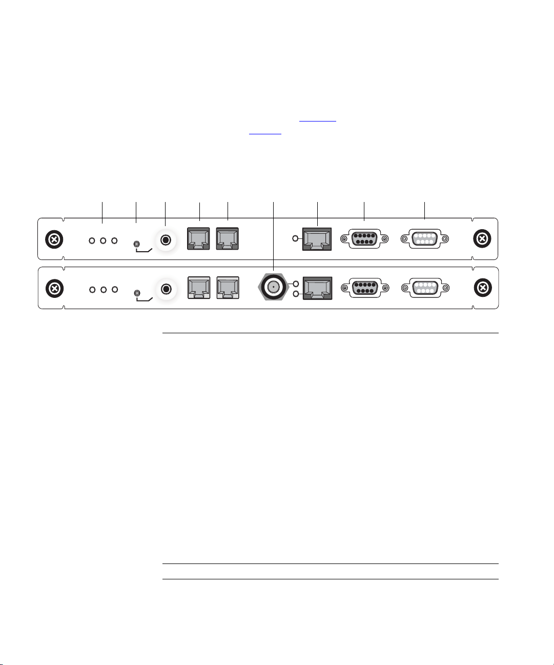
Figure 4 shows the two models of the
NBX 100 NCP and Tab le 7 describes each front panel connector and
status light.
Figure 4 NBX 100 Call Processor 3C10110D (top) and 3C10110C (bottom)
123 5 67 8 94
3C10110D
3Com NBX Call Processor
3C10110C
3Com NBX Call Processor
S2S
1
S2S
1
O
3
L
MOH
V
S
O
3
L
MOH
V
S
PAGING EXT. ALERT
PAGING EXT.ALERT
BNC 10B2
10BT UPLINK
MDI
10BT UPLINK
MDI-X
COM 1 COM 2
COM 1 COM 2
Ta bl e 7 NBX 100 NCP Connectors and LEDs
1 Status LEDs S1 and S2 — Indicate operating system status.
■ S1 and S2 both flashing (approximately 2 flashes per
second). The hardware is initializing.
■ S1 on and S2 off. The operating system has started
successfully.
■ S1 and S2 are both on. The operating system software has
not started successfully.
■ S1 and S2 flash in an alternating pattern. A file system
check is in progress, possibly due to an improper
shutdown. The boot process will take longer than normal.
S3 — Indicates the status of Music-On-Hold (MOH).
■ S3 flashing (approximately 2 flashes per second). The MOH
processor is initializing. If this flashing continues for more
than 2 minutes, the processor has not started successfully.
■ S3 solid on. The MOH processor has started successfully.
■ S3 flashing slowly (approximately 1 second on and 1
second off). The MOH processor has started successfully,
but no music source is connected.
2 VOL This adjusting screw controls the volume of Music-On-Hold.
3 MOH Mini-jack (mono or stereo) that accepts Music-On-Hold audio
(maximum 2V peak to peak) from the line output of a CD
player, tape player, or other music source.

NBX IP Telephony Platforms 29
Table 7 NBX 100 NCP Connectors and LEDs (continued)
SuperStack 3 NBX
V5000 Gateway
Chassis
4 Paging This RJ-11 connector provides an audio output or a dry
5 Ext. Alert
6 BNC 10B2
(3C1011C only)
and LINK LED
7 10BT Uplink
and LINK LED
8 COM1 DB-9 connector that provides an RS-232 (DCE) TTY terminal
9 COM2
contact switch connection for use with a public address
system.
Reserved for future use.
BNC connector to connect to an external Ethernet switch or
hub.
The older 3C10110C Network Call Processor (no longer
available) includes a BNC connector and an RJ-45 connector
for uplink connections. The BNC and RJ-45 connectors are
alternative connections for a single port. They cannot be used
simultaneously.
If you use the 10BT Uplink connector, be sure to program the
switch or router on the other end for 10 MB operation.
RJ-45 connector provides means to connect to an external
Ethernet switch or hub. Be sure to program the switch or
router on the other end for 10 MB operation.
connection for access to system CLI commands and status
messages. For information on how to connect to the NCP
using the Console connector, see
an NCP” on page 169.
Reserved for future use.
“Connecting a Computer to
The SuperStack 3 NBX V5000 Gateway Chassis Figure 5, contains four
card slots so that you can connect optional interface cards to your system.
As shipped from the factory, the top three have faceplates and the fourth
is left open. For installation instructions, see
Chapter 2.
The 3C10200B is an updated version of the 3C10200, which is no longer
available. The update removed one port (3 in
Figure 5) and improved the
switchover performance of the Ethernet ports so that both ports have
connectivity prior to switchover.

30 CHAPTER 1: INTRODUCTION
Figure 5 SuperStack 3 NBX Chassis 3C10200 (top) and 3C10200B (bottom)
132
10M Shared
10/100M Switched
10M Link
100M Link
10/100M Switched
10M Link
100M Link
3C10200 NBX Gateway Ch ass is
10/100M Switched
10M Link
100M Link
10/100M Switched
10M Link
100M Link
3C10200B NBX V5000 Chassis
Ta bl e 8 SuperStack 3 NBX V5000 Gateway Chassis Connectors
1 4-slot chassis Removable faceplates installed.
2 10/100 Mbps switched Ethernet
connection
Two redundant uplink ports. Use the
upper port to connect to the LAN. The
lower port is normally inactive and
becomes active only if the upper port
experiences a link failure. On the
3C10200B, both ports show a positive
link status even though only one port
at a time is active.
3 10 Mbps shared Ethernet
One port (3C10200 only)
connection
You must use straight-through Ethernet cable connections; you cannot
use MDI/MDIX connections.

NBX IP Telephony Platforms 31
Gateway Chassis Redundant Power Supply
You can attach a redundant power supply to the RPS connector on the
back of the NBX V5000 Gateway Chassis.
Ta bl e 9 describes the items that
you must purchase, assemble, and connect to the chassis. See your 3Com
NBX Voice-Authorized Partner for purchasing details.
CAUTION: If you are using the 3Com SuperStack Advanced Redundant
Power System (ARPS) as a backup power supply for the NBX V5000
Gateway Chassis, you can have no more than 2 Analog Terminal Cards of
Models 3C10117, 3C10117A, or 3C10117B-INT per chassis. This
restriction does not apply to the 3C10117C Analog Terminal Card.
Ta bl e 9 SuperStack 3 NBX Redundant Power Supply Components
Order Number Description Quantity
3C16071B SuperStack ARPS Chassis 1
3C16074A Type 2A, 100W Power Module (NLP100-9640) 2
3C16078 Type 2 “Y” Cable 1
To connect the redundant power supply to the NBX V5000 Gateway
Chassis:
1 Assemble the redundant power supply according to the instructions in
the SuperStack ARPS documentation.
2 Attach the “Y” cable to the RPS connector on the back of the
SuperStack
3 NBX V5000 Gateway Chassis.
3 Connect the SuperStack ARPS chassis to a source of AC power.

32 CHAPTER 1: INTRODUCTION
NBX Cards and Devices
This section lists NBX cards available from 3Com that can you can use
with an NBX system.
Before you install any Analog Line Cards or Digital Line Cards, you may
want to configure the Dial Prefix settings. For information on this topic,
see “Dial Prefix Settings” in Chapter 2 in the NBX Administrator’s Guide or
the NBX NetSet Help at Dial Plan > Operations > Dial Prefix Settings.
Analog Line Card The NBX Analog Line Card connects up to four analog telephone lines
from the Central Office (CO) to the NBX system.
Figure 6 NBX Analog Line Card (3C10114)
2
2
3
3
4
1234
4
1234
CONSOLE
CONSOLE
3C10114
3Com NBX Analog Line Card
3C10114C
3Com NBX Analog Line Card LS
PFT
PFT
1
Figure 7 NBX Analog Line Card (3C10114C)
1
Functionally, 3C10114 and 3C10114C are identical. However, 3C10114C
uses different internal components so that 3C10114C requires NBX
software release R4.1 or higher. Each Analog Line Card contains the
following lights and connectors:
■ Status Lights (1 through 4) — Each light shows the status of the
associated line.
Initialization (prior to Release R4.1):
■ All four lights flash in unison — Hardware is initializing.
■ A light flashes on twice, off for 2 seconds — Associated port
has been initialized successfully.
Initialization (Release R4.1 and higher):
■ Fast steady blink — Waiting for software download.
■ Solid on — Software has been downloaded. The flash memory on
the board is being loaded.

NBX Cards and Devices 33
■ Slow, non symmetric blinking pattern — Waiting for the
completion of the binding process to the NCP.
Operation:
■ Off for 9 to 10 seconds, on briefly — Idle, the line is not in use.
■ On for 9 to 10 seconds, off briefly — A telephone call is
connected on this port.
■ Console Connector — This DB-9 connector provides an RS-232
(DCE) TTY terminal connection for maintenance access.
T1 Digital Line Card The optionalT1 Digital Line Card lets you connect a T1 line to the NBX
system. When configured as standard T1 (DS1), the T1 card supports
in-band signaling of 24 DS0 (64 Kbps) “voice” channels and a variety of
signaling types and protocols. The T1 carries data at a rate of 1.544
Mbps. When configured as ISDN PRI, the T1 card supports 23 voice
channels with PRI services such as Direct Inward Dialing (DID).
You must have an external Channel Service Unit (CSU) when you use the
3C10116C T1 Digital Line Card. 3C10116D includes an onboard CSU.
The 3C10116D can provide CSU performance statistics, supports
loopback testing, and can be configured as a remote device that
communicates with its NCP over a routed network.
3C10116C
3Com NBX Digital Line Card
ISDN PRI services require specific circuit provisioning, which you must
obtain before you can use the T1 card in PRI mode. See Appendix B
for
more information.
Figure 8 T1 Digital Line Card (3C10116C)
CF
T1
RA
Nominal
LB
Figure 9 T1 Digital Line Card (3C10116D)
10BT UPLINK
MDI-X
CONSOLE

34 CHAPTER 1: INTRODUCTION
The 3C10116C T1 Digital Line Card has these lights and connectors:
■ T1 — This RJ-48C connector makes a patch cord connection to a T1
interface (CSU/DSU).
■ Status Lights — These lights indicate the status of the card’s
signaling, synchronization, and loop back test.
■ CF — On indicates a Carrier Failure. The T1 card is not receiving
carrier signals from the far end of the T1 line.
■ RA — On indicates a Remote Alarm. The far (remote) end of the T1
line is not receiving appropriate signaling from the T1 board.
■ LB — On indicates that loop-back testing is in progress.
■ Nominal — On indicates ready to send and receive information.
■ 10BASE-T Uplink — This RJ-45 Ethernet connector connects the T1
card to an external LAN hub or switch. You can use this connector to
isolate T1 traffic. If the T1 Digital Line Card is used in an SuperStack
3
NBX V5000 Gateway Chassis, do not use this connector because the
chassis has an Ethernet connector to connect the chassis to the LAN.
If you use the Uplink connector, be sure to program the switch or router
on the other end for 10BASE-T 10 MB operation.
■ Console — This DB-9 connector provides an RS-232 (DCE) TTY
terminal connection for maintenance access.
The 3C10116D T1 Digital Line Card has the following lights and
connectors:
■ T1 — This RJ-48C connector makes a patch cord connection to a T1
interface.
■ Status Lights — These lights indicate the status of the T1 card’s
signaling, synchronization, and loop back test.
■ CO — Central Office:
Amber — Alarm condition at the remote end or the CO is not
connected or available.
Green — No alarm condition.
■ POST — Power On Self Test
Off — POST test is running. The test runs approximately 5 seconds
after you apply power to the board. After 5 seconds, Off indicates
the POST test failed.

NBX Cards and Devices 35
Green — POST test completed successfully.
■ DCH — D channel status of an ISDN PRI connection
Off — No T1 or T1 PRI line is attached or the card does not need a
D channel, such as when the card is running T1-robbed-bit.
Green — Card is configured for ISDN PRI operation and an active
PRI connection has been established.
Amber — The D channel has not yet been established. It can take
several seconds after the card has completed its power up tests for
the card to establish a connection with the PRI trunk. If the DCH
light goes to amber after the connection has been established, it
can mean that an active control channel connection through the
PRI line has been lost.
■ DNLD — Download
Flash — The card is downloading software from the NBX Network
Call Processor.
Green — The download is complete or the Power-On-Self-Test
(POST) is running.
Amber — The download was interrupted before it was completed.
On a LAN, the download process runs quickly. If the download
from NCP to digital line card must travel a routed network path,
the download can take a few minutes. If the DNLD light remains
amber, it can indicate a severely congested network or a hardware
problem with the T1 card.
■ CALL — Call audio traffic
Off — No audio traffic on the T1 link.
Flashing — Audio traffic is present.
■ CARD — Card Software Status
Green — The card has finished downloading software from the
NCP and all software processes have started successfully.
Amber — A problem with one or more of the software processes
running on the card. The card automatically reboots itself if it
detects a problem with any of its software processes.
■ DSP — Reserved for future use
■ NCP — Network Call Processor
Amber — The card is trying to establish contact with an NCP.

36 CHAPTER 1: INTRODUCTION
Green — The card has established contact with an NCP.
■ LNK — Ethernet link.
Green — The 10/100 Uplink port is connected to a 10Mb or to a
10/100 Mb hub or switch.
Red — The 10/100 Uplink port is connected to a 100 Mb hub or
switch.
Off — There is no connection to the 10/100 Uplink port.
■ ACT— Ethernet activity.
Rapid blink — Data is passing into or out of the T1 card through
the 10/100 Uplink port.
■ 10/100 Uplink — This RJ-45 Ethernet connector connects the T1 card
to an external LAN hub or switch. You can use this connector to
isolate T1 traffic. If the T1 Digital Line Card is used in a SuperStack
3
NBX Gateway Chassis, do not use this connector because the chassis
has an Ethernet connector to connect the chassis to the LAN.
■ Console — This DB-9 connector provides an RS-232 (DCE) TTY
terminal connection for maintenance access.
CAUTION: This equipment does not operate when the main power fails.
E1 Digital Line Card The E1 Digital Line Card, used outside of North America, provides E1
connectivity using the ISDN PRI protocol. It carries data at a rate of 2.048
Mbps and can carry 32 channels, each with 64 Kbps. Thirty of these
channels are available for calls. Like the T1 ISDN PRI Card, the E1 PRI Card
supports PRI software features such as DID.
3C10165D includes an onboard CSU. The 3C10165D can provide CSU
performance statistics, can be enabled for loopback testing, and can be
configured as a remote device that communicates with its NCP over a
routed network.
ISDN PRI services require specific circuit provisioning, which you must
obtain before using this card. See Appendix B
for more information.

Figure 10 E1 Digital Line Card (3C10165C)
Figure 11 E1 Digital Line Card (3C10165D)
Each 3C10165C E1 card has the following lights and connectors:
■ E1 — This RJ-48C connector makes a connection to an ISDN interface
channel service unit/data service unit (CSU/DSU).
■ Status Lights — These lights indicate the status of the card’s
signaling, synchronization, and loop back test.
■ CF — On indicates a Carrier Failure. The card is not receiving carrier
signals from the far end of the E1 line.
NBX Cards and Devices 37
■ RA — On indicates a Remote Alarm. The far end of the E1 line is
not receiving appropriate signaling from the E1 board.
■ LB — On indicates that loop-back testing is going on.
■ Nominal — On indicates ready to send and receive information.
■ 10BASE-T Uplink MDI — This RJ-45 Ethernet connector connects the
card to an external LAN hub or switch. If the E1 Digital Line Card is
used in a SuperStack
3 NBX V5000 Gateway Chassis, do not use this
connector because the chassis has an Ethernet connector to connect
the chassis to the LAN.
If you use the Uplink connection, be sure to program the switch or router
at the other end for 10BASE-T 10 MB operation.
■ Console — This DB-9 connector provides an RS-232 (DCE) TTY
terminal connection for maintenance access.
Each 3C10165D E1 Digital Line Card has the following lights and
connectors:
■ E1 — This RJ-48C connector makes a patch cord connection to a E1
interface.

38 CHAPTER 1: INTRODUCTION
■ Status Lights — These lights indicate the status of the card’s
signaling, synchronization, and loop back test.
■ CO — Central Office:
Amber — Alarm condition at the remote end or the CO is not
connected or available.
Green — No alarm condition.
■ POST — Power On Self Test:
Off — POST test is running. The test runs approximately 5 seconds
after you apply power to the board. After 5 seconds, Off indicates
that the POST test failed.
Green — POST test completed successfully.
■ DCH — D channel status of an ISDN PRI connection
Off — No E1 or E1 PRI line is attached.
Green — Card is configured for ISDN PRI operation and an active
PRI connection has been established.
Amber — The D channel has not yet been established. It can take
several seconds after the card has completed its power up tests for
the card to establish a connection with the PRI trunk. If the DCH
light goes to amber after the connection has been established, it
can mean that an active control channel connection through the
PRI line has been lost.
■ DNLD — Download
Flash — The card is downloading software from the NCP.
Green — The download is complete or the Power-On-Self-Test
(POST) is running.
Amber — The download was interrupted before it was completed.
On a LAN, the download process is completed quickly. If the
download from NCP to digital line card must travel a routed
network path, the download may take a few minutes. If the DNLD
light remains amber, it can indicate a severely congested network
or a hardware problem with the card.
■ CALL — Call audio traffic
Off — No audio traffic on the T1 link.
Flashing — Audio traffic is present.
■ CARD — Card Software Status

NBX Cards and Devices 39
Green — The card has finished downloading software from the
NCP and all software processes have started successfully.
Amber — A problem with one or more of the software processes
running on the card. The card automatically reboots itself if it
detects a problem with any of its software processes.
■ DSP — Reserved for future use
■ NCP — Network Call Processor communications status
Amber — The card is trying to establish contact with an NCP.
Green — The card has established contact with an NCP.
■ LNK — Ethernet link status
Green — The 10/100 Uplink port is connected to a 10Mb or to a
10/100 Mb hub or switch.
Red — The 10/100 Uplink port is connected to a 100 Mb hub or
switch.
Off — There is no connection to the 10/100 Uplink port.
■ ACT— Ethernet activity
BRI-ST Digital Line
Card
Rapid blink — Data is passing into or out of the card through the
10/100 Uplink port.
■ 10/100 Uplink — This RJ-45 Ethernet connector connects the E1 card
to an external LAN hub or switch. You can use this connector to
isolate E1 traffic. If the E1 Digital Line Card is used in a SuperStack
3
NBX V5000 Gateway Chassis, do not use this connector because the
chassis has an Ethernet connector to connect the chassis to the LAN.
■ Console — This DB-9 connector provides an RS-232 (DCE) TTY
terminal connection for maintenance access.
If you require an alternative (bare wire-end) cable to use with the ISDN
PRI Digital Line Card, contact your 3Com NBX Voice-Authorized Partner.
CAUTION: This equipment does not operate when the main power fails.
The ISDN BRI-ST (Basic Rate Interface) Digital Line Card (Figure 12) has
four separate ports, each of which accommodates two B channels and
one D channel. Each B channel carries user data at 64 Kbps and the
channel operates at 16 Kbps. If the two B channels are bonded, the
D
transmission rate is 128 Kbps.

40 CHAPTER 1: INTRODUCTION
Figure 12 BRI-ST Digital Line Card (3C10164C)
3C10164C
3Com NBX Quad BRI-S/T Card
D
1 32
B1
B2
CAUTION: The BRI-ST Digital Line Cards are not approved for use in the
United States or Canada.
■ Status Lights — Each port has three status lights:
CONSOLE
D
B1
B2
■ D — On when this signaling channel is active.
■ B1 — On when this data channel is active (a call is in progress).
■ B2 — On when this data channel is active (a call is in progress).
D
B1
B2
4
D
B1
B2
During the Auto Discover process:
■ Each status light turns amber briefly, starting with span 1 (channels
D, B1, and B2) and continuing through span 4 (channels D, B1, and
B2). After approximately 30 seconds, the B1 status light on all four
spans turns green for approximately 1 minute. All lights turn off
when the Auto Discover process is complete.
After you connect an ISDN BRI span to a port:
■ The D light turns green if the span is operating properly and turns
amber if there is a problem. For a span that is operating properly,
when the NBX system initiates or receives a call on a B channel, the
corresponding light initially turns amber. When the call is
answered, the light turns green.
■ Console — This DB-9 connector provides an RS-232 (DCE) TTY
terminal connection for maintenance access.
CAUTION: This equipment does not operate when the main power fails.
10BASE-T Uplink Card The 10BASE-T Uplink Card provides eight 10BASE-T Ethernet ports to
connect 3Com Telephones (or other 10BASE-T devices) to the LAN. The
Uplink Card (
Figure 13 NBX Uplink Card (3C10370)
PWR1123456788
3C10370
3Com NBX Uplink Card
3C10370) replaces the 10BASE-T Hub Card (3C10115).

NBX Cards and Devices 41
The NBX 10BASE-T Uplink Card contains these lights and connectors:
■ Status Lights (PWR and 1 through 8) — These lights indicate the
status of power to the hub and the status of the 10BASE-T ports.
■ Ethernet Hub Ports (8) — These RJ-45 MDI-X ports connect devices
to the LAN.
Analog Terminal Card Each Analog Terminal Card allows connections for up to four analog
(2500-series compliant) telephones and Group-3 fax machines. When an
Analog Terminal Card senses that a port is being used for fax
transmission, it switches that port to reliable mode. Unlike voice transfers,
which drop packets due to congestion, reliable mode transmissions take
as much time as needed to ensure that there are no lost packets.
However, reliable mode also uses twice the bandwidth.
CAUTION: If you are using the 3Com SuperStack ARPS (Advanced
Redundant Power Source) as a backup power supply for the SuperStack 3
NBX V5000 Gateway Chassis, you can have no more than 2 Analog
Terminal Cards of Models 3C10117, 3C10117A, or 3C10117B-INT per
Gateway Chassis. This restriction does not apply to the 3C10117C Analog
Term ina l Ca rd.
Figure 14 NBX Analog Terminal Card (3C10117B-INT)
2
NOT FOR TELECOM USE
3C10117B-INT
1
3Com NBX Analog Terminal Card
Figure 15 NBX Analog Terminal Card (3C10117C)
2
NOT FOR TELECOM USE
3C10117C
3Com NBX Analog Terminal Card
1
3
3
4
1234
4
1234
CONSOLE
CONSOLE

42 CHAPTER 1: INTRODUCTION
Each Analog Terminal Card has the following lights and connectors:
■ Analog Connectors (1 through 4) — Four RJ11connectors enable
you to connect analog devices to the NBX system.
■ Status Lights (1 through 4) — Each light indicates the status of the
associated port.
Initialization:
■ Fast steady blink — Waiting for software download.
■ Solid on – Software has been downloaded. The flash memory on
the board is being loaded.
■ Slow, non-symmetric blinking pattern — Waiting for the
completion of the binding process to the NCP.
Operation:
■ Off for 9 to 10 seconds, on briefly — Idle, telephone is on hook.
■ On for 9 to 10 seconds, off briefly — Idle, telephone is off hook.
■ Console Connector — This DB-9 connector provides an RS-232
(DCE) TTY terminal connection for maintenance access.
Analog Terminal
Adapters
The single-port Analog Terminal Adapter (ATA) is a desktop box that
connects a single analog telephone or fax machine to an NBX system.
Figure 16 Analog Terminal Adapter (3C10400) — Front View
POTS Status
Power
PC
Link
LAN
Link
Figure 17 Analog Terminal Adapter (3C10400) — Rear View
24 VDC
IOIOI
NBX Analog Terminal Adapter
POTS
LAN PC

NBX Cards and Devices 43
The 3C10400 ATA can accept power over the Ethernet cable. It meets the
IEEE 802.3af standard for Power over Ethernet. It can also accept power
from an AC power adapter plugged into a wall socket. The 3C10400 is a
Class 3 PoE device.
The 3C10400 ATA has an RS232 DB9 connector that allows a technician
to access a command line interface for the device.
Only qualified 3Com service personnel should use the serial diagnostic
port.
The Analog Terminal Adapter (3C10400) has these lights and connectors:
■ Power Light — The light below the icon for power indicates that the
ATA is receiving power.
■ POTS Status Lights (S1, S2, S3) — The POTS (Plain Old Telephone
Service) status lights indicate the status of the Analog Port. S3 is on
when the analog device is in use. S2 blinks briefly every 10 seconds
when an analog device is connected to the ATA. If no analog
telephone is connected, S2 is always off. S1 is reserved for future use.
■ PC Link Light — On indicates that there is an external network device
connected to the ATA.
■ LAN Link Light — On indicates that the ATA is connected to the
network.
■ 10101 — Serial port for diagnostics.
■ POTS — A connection for an analog telephone or fax machine.
■ PC — A connection for a network device.
■ LAN — A connection to the network.

44 CHAPTER 1: INTRODUCTION
3Com Telephones 3Com Telephones provide the familiar features of a business telephone
and extra features such as one-touch access to voice mail.
3103 Manager’s Telephone
3C01403A
Requires NBX R5.0 or higher and a Group 2license
For more information on device licenses, see“Group
Device Licenses” on page 53.
3102 Business Telephone
3C10402A
Requires NBX R4.3 or higher and a Group 2 license
3101SP Basic Telephone
(with speakerphone, shown, 3C10401SPKRA)
3101 Basic Telephone
(without speakerphone, 3C10401A)
Requires NBX R4.3 or higher and a Group 1 or higher
license
3107C Cordless Telephone (left)
3C10407A
3106C Cordless Telephone
3C10406A
Requires NBX R5.0 or higher and a Group 1 or higher
license
3100 Entry Telephone
3C10399A
■ The 3100 Entry Telephone does not include a
switch port.
■ The 3100 Entry Telephone does not support
external TAPI applications.
Requires NBX R5.0 or higher and a Group 0 or higher
license

NBX Cards and Devices 45
3105 Attendant Console
3C10405A
The 3Com Attendant Console provides attendant
(receptionist) access and monitoring for up to 100
extensions.
Requires NBX R4.3 or higher and a Group 2 license
NBX systems also support legacy 3Com telephones: 2101 Basic Telephones,
1102, 2102 and 2102-IR Business Telephones, and 1105 Attendant Consoles.
CAUTION: To avoid damage to the 3Com telephone, do not connect a
3Com telephone or Attendant Console directly to a standard telephone
line. Although the RJ-11 connector for a traditional telephone fits into the
3Com telephone’s RJ-45 jack, the electrical interfaces are not compatible
and the telephone will not work.
Legacy Link Devices 3Com Legacy Link Blades allow you to migrate Nortel Norstar and
Meridian telephone users to an IP infrastructure. The 3Com Legacy Link
Analog Blade is a multiport analog handset gateway card that fits into an
NBX chassis.
Third-party Devices
and Applications
Legacy Link cards put significant traffic on an NBX 100 backplane.
3Com recommends that you install no more than two Legacy Link cards
in an NBX 100 chassis. If you have Digital Line Cards (T1/E1) in the same
chassis, you must connect the Digital Line Cards to an Ethernet switch via
the uplink port on the front of the cards to reduce backplane traffic.
These limitations do not apply to the SuperStack3 NBX V5000 Chassis.
3Com works with third-party suppliers to provide a range of devices and
software applications that are compatible with NBX systems. For more
information on third-party offerings, see your 3Com NBX
Voice-Authorized Partner.

46 CHAPTER 1: INTRODUCTION
Optional Software The NBX Resource Pack CD includes a number of optional components.
Two applications are counterparts of two NBX system hardware devices:
■ NBX Complement Attendant Software (CAS) runs on a PC and
provides the functions of an Attendant Console. You install the
Complement Attendant Software from the NBX Resource pack CD.
You must purchase a license and use the NBX NetSet utility to install it
before you can use CAS.
■ pcXset™ Soft Telephone runs on a PC and provides most of the
features of a 3Com Business Telephone. The NBX system comes with
one pcXset license. To use more than one pcXset client with an NBX
system, you must purchase additional licenses and use the NBX NetSet
utility to install them. You add a pcXset client as a telephone in the
NBX NetSet utility and specify the host PC’s NIC MAC address as the
device identifier.
In addition, these software applications and documents are available on
the NBX Resource
■ NBX Call Reports enables you to retrieve the call detail records that
are kept on the NBX system, present them in report format and export
them in a format suitable for other reporting applications. No license
required. NBX Call Reports is available from the NBX Resource Pack
CD and from within the Downloads tab of the NBX NetSet utility.
Pack CD:
■ NBX TAPI Service Provider (NBXTSP) provides the interface between
the NBX system and the Microsoft Telephone API to enable software
applications to use NBX Telephone services and features.
■ Desktop Call Assistant is a TAPI-based program that allows you to
dial calls from your computer screen.
■ Palm Dialer enables you to look up a telephone number in your Palm
Address Book application and then place a call to that number on an
NBX 2102-IR Business Telephone (a legacy device) through the phone’s
infrared port.
■ NBX ConneXtions allows you to use an appropriately configured
Windows system as an H.323 gateway for use with NBX systems.
■ NBX Media Driver works with the NBXTSP to provide external
software applications access to the features of the NBX system.
■ 3Com Network Supervisor is an evaluation version of the 3Com
network element management system.

NBX Licensing 47
■ NBX LabelMaker is available through the NBX NetSet utility. It
enables you to define custom telephone button labels. You can create,
print, and save the labels for later use.
■ 3Com Telephone Local Configuration Application is a PC-based
utility that enables you to manually configure the basic settings for
NBX devices that do not have an LCD display, such as the 3100 Entry
Telephone and the 3105 Attendant Console.
NBX Licensing Each NBX system is shipped with a total-device-limit license that controls
the total number of devices that you can configure on the system.
However, there are other factors to consider when determining what
your system can support. Your configuration must conform to all of these
limits:
■ The limit imposed by the total system license (explained next)
■ The individual limits on certain device types (explained later in this
topic)
■ The license requirements for some hardware and software
What Counts Toward the Total Device Limit?
NBX systems count many physical devices and certain software
applications as devices toward the total device limit:
■ Physical Devices — Each 3Com Telephone, each Analog Terminal
Adapter, each channel on a Digital Line Card, and each port on an
Analog Line Card counts as one device. Physical device limits are listed
Ta bl e 10.
in
■ Software “Devices” — Each NBX Media Driver port counts as one
device. Each installation (client) of the pcXset Soft Telephone
application counts as one device.
What Does NOT Count Toward the Total Device Limit?
The NBX systems do not count most applications toward the total device
limit, although some may be governed by license limits. Examples: voice
mail ports, automated attendant ports, Call Park zones, System Speed
Dials, and any other item with “None” in the second column in
Ta bl e 10.

48 CHAPTER 1: INTRODUCTION
Individual Device
Limits
Licensed Device
Limits
How the System
Limits Interact
Certain individual device types are limited to a maximum per system
because of internal product rules. For example, the NBX Analog Line Card
has 4 ports. Although each of these ports counts as a device, the NBX
system architecture limits the system to 180 Analog Line Cards (4 x 180),
and thus the system can support a maximum of 720 not 1500 analog line
ports.
Certain devices and applications have limits that are governed by licenses.
Device licensing is explained in detail in
“Device Licenses” on page 52.
Your 3Com NBX Voice-Authorized Partner can provide details on available
incremental device licences.
As you add devices to an NBX system, you must keep in mind all of these
limitations:
■ To ta l device limit for the system
■ Individual device limit for certain device types
■ License limit for certain device types
■ System memory
Example: Your NBX V3000 has the memory upgrade installed, it is
licensed for 1500 total devices and you want to configure 450
telephones:
■ You configure 6 NBX Analog Line Cards, and 12 NBX Analog Terminal
Cards (for analog telephones and FAX machines).
The total device count is now (6 x 4) + (12 x 4) = 72.
■ You then configure 450 3Com Telephones.
The total device count is now 522. You can configure 978 additional
devices (1500–522).
■ You want to configure 200 Attendant Consoles, but, because the
individual device limit for Attendant Consoles is 100, you can
configure only 100 Attendant Consoles.
The total device count is now 622. You can configure 878 additional
devices (1500–622).
■ You want to add Virtual Tie Lines (VTLs), but you can add only 48
because that is the maximum license level available for VTLs.

NBX Licensing 49
VTLs do not count toward the device limit, so the total device count
remains at 622. So, after you add 48 VTLs, you can still configure up
to 878 additional devices.
Table of Maximum
Device Counts
Ta bl e 10 lists each NBX device and application, with information on
whether it counts toward the total device count and the maximum
number allowed per NBX system.
For the current device and license configuration on your system, see
NetSet > Operations > Licenses as well as the Usage Report
NBX
accessible from the Licenses screen.
Some of the limits in Tabl e 1 0 can be affected by your dial plan. The
3-digit dial plan does not support enough extensions to allow you to
reach all the device limits.
Ta bl e 10 Detailed Device Limits
Per-Unit
Device Count
Device/application
Description
1102, 2102, or
2102-IR Business
Telephone
2101 Basic
Telephone
1105 Attendant
Console
3106C Cordless
Telephone
3107C Cordless
Telephone
The limits on cordless telephones are due to radio frequency issues rather than system capacity limits. For more
information, see
3103 Manager’s
Telephone
3102 Business
Telephone
3101 or 3101SP
Basic Telephone
3100 Entry
Telephone
Toward Total
System Count
1 1500 250 1500 200 No
1 1500 250 1500 200 No
1 100 100 100 50 No
1 10 10 10 10 Yes
1 3 3 3 3 Yes
“Cordless Telephone Installation Notes” on page 113.
1 1500 250 1500 200 Yes
1 1500 250 1500 200 Yes
1 1500 250 1500 200 Yes
1 1500 250 1500 200 Yes
NBX V3000:
Max with
Memory
Upgrade
NBX V3000:
Max without
Memory
Upgrade
SuperStack 3
System
Maximum
NBX 100
System
Maximum
Device or
Site License
Required?

50 CHAPTER 1: INTRODUCTION
Table 10 Detailed Device Limits (continued)
Per-Unit
Device/application
Description
3105 Attendant
Console
pcXset Soft
Telephone
NBX Media Driver
(for WAV devices)
Polycom IP 3000
Speaker Phone
Legacy Link Handset
Gateway card
NBX Analog
Terminal Card (ATC)
NBX Analog
Terminal Adapter
(ATA)
NBX Analog Line
Card
NBX T1 Card
(DS1)
NBX T1 Card
PRI)
(ISDN
NBX E1 Card
(ISDN
PRI)
NBX ISDN BRI-ST
card
System Architecture Attributes
Virtual Tie Lines None 48 8 48 8 Yes
ConneXtions (H323)
ports
Bridged Extensions None 400 Primary
Application and Call Processing Attributes
Auto Attendants None 100 100 100 100 No
Device Count
Toward Total
System Count
1 100 100 100 50 Yes
1 per pcXset PC
telephone
client
1 driver/system
enables the
max allowable
number of
WAV devices
1 1500 250 1500 200 Yes
16
(16-port card)
4
4-port card)
1 1500 250 1500 200 No
4 per card 720 ports
24 per card 720 channels
23 per card 713 channels
30 per card 720 channels
8 per card 720 channels
None 100 100 100 16 Yes
NBX V3000:
Max with
Memory
Upgrade
1500 250 1500 200 Yes
1500 250 1500 200 Yes
1488 (93 cards) 240 (15 cards) 1488 (93 cards) 192 (12
1500
(375 cards)
(180 cards)
(30
cards)
cards)
(31
(24
cards)
(90
cards)
1200
Bridged
NBX V3000:
Max without
Memory
Upgrade
248
(62 cards)
248 ports
(62 cards)
240 channels
(10
cards)
230 channels
cards)
(10
240 channels
(8
cards)
248 channels
(31
cards)
400 Primary
1200
Bridged
SuperStack 3
System
Maximum
1500
(375 cards)
720 ports
(180 cards)
720 channels
(30
cards)
713 channels
cards)
(31
720 channels
(24
cards)
720 channels
(90
cards)
400 Primary
1200
Bridged
NBX 100
System
Maximum
cards)
248
(62 cards)
100 ports
(25 cards)
72 channels
(3 cards)
69 channels
(3 cards)
90 channels
(3 cards)
96 channels
(12 cards)
100 Primary
300
Bridged
Device or
Site License
Required?
Yes
No
No
No
No
No
No
No

Table 10 Detailed Device Limits (continued)
NBX Licensing 51
Per-Unit
Device/application
Description
The 3-digit dial plan might not provide enough extensions to support 100 Auto Attendants.
Voice Mail Ports None 72 12 72 12 Yes (above 4
Voice Mailboxes None 1500 250 1500 200 Yes (covered
Automatic Call
Distribution Groups
ACD Groups, Hunt Groups, and Calling Groups all count towards the same total. For example, on a V3000 system, if
you have 50 Hunt Groups, the system can also support any combination of 50 ACD and Calling Groups.
Phantom Mailboxes None 1000 1000 1000 150 No
The 3-digit dial plan does not provide enough extensions to support 1000 Phantom Mailboxes.
Call Park Zones None 100 100 100 9 with the
The 3-digit dial plan might not provide enough extensions to support 100 zones.
Call Pickup None 100 100 100 32 No
Conference Calls None 12 12 12 4 No
Directed Pickup None 50 50 50 10 No
Group Pickup None 50 50 50 32 No
Hunt Groups or
Calling Groups
The 3-digit dial plan might not provide enough extensions to support 100 groups.
ACD Groups, Hunt Groups, and Calling Groups all count towards the same total. For example, on a V3000 system, if
you have 50 Hunt Groups, the system can also support any combination of 50 ACD and Calling Groups.
Music On Hold None 1 1 1 1 No
Paging None 3 3 3 3 No
Page Zones None 9 9 9 9 No
System Speed Dials None 100 100 100 100 No
Personal Speed Dials None 100 100 100 100 No
Device Count
Toward Total
System Count
0 100 48 100 48
None 100 100 100 48 No
NBX V3000:
Max with
Memory
Upgrade
NBX V3000:
Max without
Memory
Upgrade
SuperStack 3
System
Maximum
NBX 100
System
Maximum
3-digit dial
plan; 100
with the
4-digit plan.
Device or
Site License
Required?
ports)
by total
system
device
license)
Yes
(above 2
agents/group)
No

52 CHAPTER 1: INTRODUCTION
Table 10 Detailed Device Limits (continued)
Per-Unit
Device/application
Description
Call Detail Reporting None 1 1 1 1 No
Call Record and
Monitor
TAPI Route Points None 100 100 100 48 No
The 3-digit dial plan might not provide enough extensions to support 100 TAPI Route Points.
Device Count
Toward Total
System Count
None 1 1 1 1 No
NBX V3000:
Max with
Memory
Upgrade
NBX V3000:
Max without
Memory
Upgrade
SuperStack 3
System
Maximum
NBX 100
System
Maximum
Device or
Site License
Required?
Device Licenses The basic NBX system includes default licenses. You can add licenses to
increase the system capacity.
Ta bl e 11 shows the defaults and maximums
for licensed items on each NBX platform.
Ta bl e 11 NBX Device Licensing Summary
License NBX 100 SuperStack 3 NBX NBX V3000
Default Max. Default Max. Default Max.
Device 200 200 250 1500 250 1500
Voice mail
(ports/hrs.)
Virtual Tie Lines 1 8 1 48 1 48
Disk Mirroring na na 0 1 na na
NBX pcXset 1 200 1 750 1 750
NBX ConneXtions 1 16 1 100 1 100
NBX Media Driver 1 96 1 750 1 750
NBX VPIM
Messaging License
NBX 3rd-party
Messaging License
NBX Complement
Attendant Software
(CAS) License
Call Record and
Monitor License
Automatic Call
Distribution Agents
4/4 12/80 4/400 72/unlimited 4/400 72/unlimited
0 Site 0 Site 0 Site
0 Site 0 Site 0 Site
0 Site 0 Site 0 Site
0 Site 0 Site 0 Site
2 200 2 200 2 200

NBX Licensing 53
Table 11 NBX Device Licensing Summary (continued)
License NBX 100 SuperStack 3 NBX NBX V3000
Default Max. Default Max. Default Max.
Group 0 Devices
(3100)
Group 1 Devices
(3101, 3101SP,
3106, 3107)
Group 2 Devices
(3103, 3102, 3105)
Group 3 Devices Reserved for future use.
Group 4 Devices Reserved for future use.
0 200 0 1500 0 1500
0 200 0 1500 0 1500
0 200 0 1500 15 1500
NBX Licensing Summary Notes
■ NBX cards, Analog Terminal Adapters, and legacy devices (1102,
2102, 2102-IR Business Telephones, 2101 Basic Telephones, and 1105
Attendant Consoles) do not require a license. The number of these
devices is governed solely by the system device license.
■ The NBX V3000 comes with four NBX Messaging ports and a limit of
400 hours of message storage. (A messaging port is used for each
Automated Attendant session and each voice mail session.) If you
want more than 4 ports, you must purchase and install additional NBX
Messaging licenses. To go above 12 NBX Messaging ports, you must
install the memory upgrade (3C10240) if you haven't already done so
to upgrade the device limit. If you purchase additional NBX Messaging
capacity, message storage hours are limited only by available disk
space, however, the NBX administrator can establish limits on the
number of messages, message length, and retention period.
Group Device
Licenses
NBX Group Licensing provides a flexible system of licensing NBX
telephones and attendant consoles. For licensing purposes, NBX devices
are grouped according to the features the device can support. Lower cost
devices that have fewer features are part of lower numbered License
Groups while the more capable full-featured devices are part of the
higher numbered License Groups.
Group 0 Devices
■ 3100 Entry Telephone

54 CHAPTER 1: INTRODUCTION
Group 1 Devices:
■ 3101 Basic Telephone
■ 3101SP Basic Telephone
■ 3106C Cordless Telephone
■ 3107C Cordless Telephone
Group 2 Devices:
■ 3103 Manager’s Telephone
■ 3102 Business Telephone
■ 3105 Attendant Console
Dynamic License
Assignment
NBX Group Licensing is a dynamic system that assigns licenses in the
most efficient manner. A Group License can activate devices belonging to
that group or devices with fewer features. For example, a Group 2 license
normally activates Group 2 devices but it may also activate Group 1 or
Group 0 devices. If a device needs a license and no license is available for
that group, the system “loans” a license from a higher license group if a
license is available in that group.
License loans are automatic. The system dynamically assigns available
licenses to devices to achieve the most efficient use of the installed
licenses. Dynamic allocation can cause a more valuable license to be used
for a less valuable telephone. For example, using a Group 2 license for a
Group 0 device might be desirable as an interim solution, but if you later
add a Group 2 device, you would probably want to purchase a Group 0
license for the Group 0 telephone and use the Group 2 license for the
Group 2 device.
These examples demonstrate the flexibility of NBX Group Licenses.
Example 1— All devices in the same License Group: You purchase
and install a package of ten Group 2 Licenses on your SuperStack 3 NBX
system and then add five 3102 Business Telephones, one 3103 Manager’s
Telephone and one 3105 Attendant Console for a total of seven Group 2
devices. The system has three Group 2 licenses still available.
Example 2 — Borrowing from the next highest License Group: You
add a 3101 Basic Telephone (Group 1 device) to your SuperStack 3 NBX
system, which has three Group 2 licenses available. You do not add a
Group 1 license to the system. The system checks for the availability of a

NBX Licensing 55
Group 1 license. Since no Group 1 licenses are available, the system
assigns a Group 2 license to the 3101 Basic Telephone. The system now
has two Group 2 licenses available.
Example 3 — Borrow from the highest License Group: You add two
3100 Entry Telephones (Group 0 device) to your SuperStack 3 NBX
system, which has two Group 2 licenses available. You do not add a
Group 0 license to the system. The system checks for the availability of a
Group 0 license, then checks for the availability of a Group 1 license, and
since there are no Group 0 or 1 licenses available, assigns the Group 2
licenses to the 3100 Entry Telephones. The system now has no licenses
available.
Figure 18 shows the section of the License Usage Report that
displays device license usage.
Figure 18 License Details Information
The first column in the License Usage
Report shows the number of device
licenses currently in use. The second
column shows the number of licenses in
each License Group that have been
installed on the system.
Example 4 — Dynamic License Group Adjustment: You add another
3103 Manager’s Telephone (Group 2 device) to your SuperStack 3 NBX
system, which has no licenses available in any group. The system will not
enable the new telephone. You could add another Group 2 license, but it
would be more cost-effective to add a less expensive Group 0 license
instead. After you add a Group 0 license, the system automatically
reassigns licenses in this manner:
■ Releases one of the Group 2 licenses that was assigned to one of the
3100 Entry Telephones.
■ Assigns the new Group 0 license to the 3100 Telephone.
■ Assigns the released Group 2 license to the new 3103 Telephone.

56 CHAPTER 1: INTRODUCTION
The system now has no licenses available.
Example 5 — Manual License Group readjustment: You add another
3103 Manager’s Telephone (Group 2 device) to your SuperStack 3 NBX
system, which has no licenses available in any group. Instead of adding a
Group 0 license, as shown in Example 4, you could manually remove one
of the telephones from the system to free a license. For example, you
could use the NBX NetSet utility to remove the 3101 Basic Telephone.
Since that telephone was using a Group 2 license, removing the
telephone makes a Group 2 license available.
Group License Notes
■ To view the number of Group Licenses you have installed on your
system open the License Summary page in the NBX NetSet utility,
Operations > Licenses. To view how the number of Group Licenses
have been allocated, including licenses loaned to different groups,
open the License Usage Report in the NBX NetSet utility, Operations
> Licenses > Usage Report.
■ To achieve the best licensing configuration, you should always add
license keys to the system (Operations > Licenses > Add License)
before you add devices.
Upgrading Device
Licenses from R4.X to
R5.0
■ If you are removing a telephone to manually readjust licenses, you
should first make sure that Auto Discover Telephones is disabled
(System Configuration > System Settings > System-wide) to
ensure that the telephone is not automatically added to the system
again.
■ A basic NBX V3000 system includes fifteen Group 2 Licenses.
Group Licensing is not available on systems prior to R5.0. Licensed
devices that are installed on a system at the time that system is upgraded
to R5.0 will have their licenses converted to appropriate License Groups:
■ 3101 and 3101SP Basic Telephone licenses convert to Group 1
Licenses
■ 3102 Business Telephone licenses convert to Group 2 Licenses
■ 3105 Attendant Console licenses convert to Group 2 Licenses

NBX Licensing 57
Rebooting from R5.X
to R4.X
If you reboot an R5.0 system to an earlier software version, these license
conversions are in effect:
■ Device licenses that were converted to Group 1 and Group 2 licenses
during the upgrade to R5.0 are active as 3101, 3102 and 3105
licenses.
■ Group 1 licenses applied after the upgrade to R5.0 are converted to
3101 licenses.
■ Group 2 licenses applied after the upgrade to R5.0 are converted to
3102 licenses.
■ Devices introduced at R5.0, 3103 Manager’s Telephones, 3100 Entry
Telephones, and 3106C and 3107C Cordless Telephones will not be
recognized. These devices were not supported prior to release R5.0.
Group Licensing, 3105 Attendant Consoles, and R4.X Software
If you reboot to R4.4 or R4.3 from R5.0, Group 2 licenses are converted
to 3102 device licenses, which means that a 3105 Attendant Console,
which is a Group 2 device, could become unavailable. The following
examples show what happens to 3105 Attendant Consoles when you
reboot from R5.0 to R4.4 or R4.3.
Example 1: Your system is running R4.3 (or R4.4) software. The system
has one 3105 Attendant Console installed and you have one 3105 device
license installed on the system. You upgrade the system to R5.0. The
3105 device license becomes a Group 2 license and the 3105 continues
to operate. You reboot the system to R4.3 or R4.4 and the 3105
continues to operate under the original 3105 device license.
Example 2:
Your system is running R4.3 (or R4.4) software. The system has
one 3105 Attendant Console installed and you have one 3105 device
license installed on the system. You upgrade the system to R5.0 software,
and then add another 3105 and a Group 2 license. You reboot the system
to R4.3 or R4.4. One of the 3105 Attendant Consoles continues to work
and the other does not because the Group 2 license that was used by the
3105 while operating under R5.0 is converted to a 3102 device license. To
enable the 3105 under R4.4 or R4.3, you need to add a 3105 device license.
Example 3: Your system is running R4.3 (or R4.4) software. The system
has one 3105 Attendant Console installed and you have two 3105 device
licenses installed on the system. You upgrade the system to R5.0
software, and then add another 3105 and a Group 2 license. You reboot
the system to R4.3 or R4.4. Both 3105s continues to work.

58 CHAPTER 1: INTRODUCTION

INSTALLING SYSTEM HARDWARE
2
COMPONENTS
This chapter explains how to install standard and optional hardware
components for the NBX Networked Telephony System. This chapter
includes information about using the Auto Discover feature to add
telephones, however, specific information about adding telephones is in
Chapter 3. This chapter covers these topics:
■ Introduction
■ International Feature Support
■ Installation Requirements
■ Installation Questions
■ Before You Begin Installation
■ Important Safety Information
■ Unpacking and Examining the Components
■ Installing the NBX System Hardware
■ Configuring NBX System Networking
■ Connecting Cards and Devices
■ Selecting Regional Software and Components
■ Using Auto Discover for Initial System Configuration
■ Connecting Telephone Lines
■ Adding External Hardware
■ Configuring Routing Devices

60 CHAPTER 2: INSTALLING SYSTEM HARDWARE COMPONENTS
Introduction This guide uses the following definitions for administrators, users, and
callers on the NBX system:
■ Administrator — The person responsible for managing and
maintaining the LAN. This person has “administrator” privileges on
the system
■ User — A person with user login privileges on the system
■ Caller — A person calling into the system
International Feature Support
For international users, the following features and devices warrant special
attention.
Power Fail Transfer For the Power Fail Transfer (PFT) feature, is available only in North
America.
CAUTION: You should have access to a mobile or analog telephone that
is connected to your standard PSTN.
Analog Terminal
Connectors
The NBX Analog Terminal Adapter, the ATA port on the NBX V3000, and
each port on the NBX Analog Terminal Card may require a telephone
connector for use outside North America. Contact your 3Com NBX
Voice-Authorized Partner for information on country-specific
requirements.
Language Support The NBX Resource Pack CD includes these localized components:
■ Telephone tones and cadences that match those used by telephone
companies in different countries
■ Localized online user documentation
■ Localized voice prompts
If the required language is not provided in the voice prompts, which you
can load and activate using the NBX NetSet utility, you can record new
Automated Attendant main menu and system-wide Time-dependent
greetings. For information on how to modify an Automated Attendant,
see the “Automated Attendant” section in Chapter 6, “NBX Messaging,”
in the NBX Administrator’s Guide.

Installation Requirements 61
Installation Requirements
Electrical
Requirements
Verify that you meet the prerequisites that are detailed in the following
sections before you install the NBX system.
3Com does not support more than one NBX system on a local area
network. You can connect NBX systems over a WAN using VTLs, as
described the NBX Administrator’s Guide, however, installing more than
one NCP on a LAN can cause unpredictable results.
Verify that the site meets the following electrical requirements.
■ Each NBX chassis requires an electrical connection.
■ The NBX system should have its own breaker-protected circuit that
uses the standard, three-wire, grounded configuration.
■ Verify that there are enough outlets and circuit capacity in the chosen
location to supply power to the NBX chassis and any auxiliary
equipment that you install, such as a paging amplifier and an MOH
device. The label on each chassis lists the electrical requirements of the
system.
■ You can eliminate the power adapter for a telephone by using a
powered Ethernet cable. See
“Connecting Power to a 3Com
Telephone” in Chapter 3 for more information.
CAUTION: 3Com strongly recommends that you use UL listed surge
suppression devices for the telephones and the local telephone lines and
an uninterruptible power supply for each NBX chassis.
Environmental
Requirements
You can install the NBX system in any clean, dry, well-ventilated location.
Take these environmental guidelines into consideration:
■ The area must be safe from water damage. A wet basement, a utility
closet, or an area near a window are not proper locations.
CAUTION: Do not use the NBX system outdoors.
■ The area must be safe from physical interference. For example, do not
put the chassis where it might be struck by a swinging door or where
cables might be disturbed by a door or by people passing by.
■ Do not install the NBX system in an area that is exposed to strong
electromagnetic fields, dust, smoke, or airborne debris.

62 CHAPTER 2: INSTALLING SYSTEM HARDWARE COMPONENTS
■ Verify that the installation site has sufficient cooling and air circulation
to maintain ambient temperatures from 0 °C through 40 °C (32 °F
through 104 °F
) and a humidity range of 5% to 85%, noncondensing.
Physical
Requirements
Local Telephone
Service
When you install an NBX system, verify that the installation site meets
these physical requirements:
■ The NBX system should be installed in a secure area. Telephone service
and voice messaging are crucial business services. Protect them from
tampering or accidental interference.
■ To rack-mount an NBX system, use a standard 486-mm (19-in.)
equipment rack, properly installed and grounded according to the
manufacturer’s instructions.
■ The NBX V3000 is 42 mm (1.6 in.) high and 355 mm (14 in.) deep.
All data connections are on the front of the chassis and power
connections are on the back.
■ The SuperStack 3 NBX V5000 Chassis is 13.3 cm (5.25 in.) high
and 30.5 cm (12 in.) deep. All data connections are on the front of
the chassis and power connections are on the back.
■ The NBX 100 chassis is 10.5 in. (264.7 mm) high and 23 cm (9 in.)
deep. All connections are on the front of the chassis.
■ Allow at least 8 cm (3 in.) of space on either side of the NBX chassis
for proper ventilation.
Before you install the NBX system, be sure that the installation site meets
the following local telephone service requirements:
■ The local telephone company has installed local telephone lines and
assigned telephone numbers.
■ If necessary, you have extended the wires from a centrally located
telephone interface panel to the installation site.
■ Each analog telephone line has dial tone.
CAUTION: 3Com strongly recommends that you use UL-listed surge
suppression devices on all local telephone lines.
■ If you are installing an optional BRI-ST, T1, or E1 Digital Line Card,
verify that the telephone company has installed BRI-ST, T1, or E1 lines
and run them to the installation location.

Installation Questions 63
Installation Questions
Who Should Install
the NBX System?
Does the Telephone
Company Need to Be
Involved?
If you have not already planned the installation, the following topics
discuss issues that you may encounter when you install the telephone
system.
A technician who understands Ethernet 10BASE-T and 100BASE-T
cabling requirements and telephony configuration should install and
configure the system. If you are using the IP capabilities of the NBX
system, the technician also needs to understand IP, subnetworks, and
DHCP (Dynamic Host Configuration Protocol).
After the initial installation, the local administrator should be able to
install additional telephones and manage the system.
If the cabling scheme has not been designed and installed, you should
consult a qualified network design engineer. Although it is not difficult to
set up a small 10BASE-T or 100BASE-T LAN, a well-designed network
should accommodate future growth without redesign. NBX system
documentation does not explain the workings of Ethernet or IP, or the
requirements for cabling a network.
You must rely on the local telephone company to provide one or more
loop-start lines and the telephone number or numbers. A fax machine
can connect to the NBX system through an Analog Terminal Adapter.
Is Any Additional
Equipment Required?
CAUTION: To avoid damage to any 3Com telephone, do not connect it
directly to a standard telephone line. Although the RJ-11 connector for a
traditional telephone fits into the 3Com telephone’s RJ-45 jack, the
electrical interfaces are not compatible and the telephone will not work.
You may need some of the following components:
■ To configure the NBX system, you need a computer equipped with a
browser, such as Microsoft Internet Explorer Release 5.5 or higher, a
network interface card, and a CD-ROM drive. You also need to
provide IP configuration parameters for the system.
■ Computers that use Computer Telephony Integration (CTI)
applications need an operating system that supports the Microsoft
TAPI 2.X standard, such as Windows XP or Windows 2000, and a
browser to download the TAPI-related NBX support software through
the NBX NetSet utility.

64 CHAPTER 2: INSTALLING SYSTEM HARDWARE COMPONENTS
■ If you choose to install the NBX system in an equipment rack, you
need a standard 486 mm (19 in.) rack.
■ You may need 10BASE-T or 100BASE-T Ethernet cable and connectors
to connect the telephones to the hub.
■ 3Com strongly recommends that you use surge suppression devices
on all local telephone lines.
■ 3Com telephones and attendant consoles that support Power over
Ethernet (PoE) do not come with AC power adapters. You can power
these devices with any IEEE 802.3af-compliant power source or with
optional AC power adapters. The packing sheet that ships with each
device shows the device power options.
What External
Devices Can Connect
to an NBX System?
What Effect Does an
NBX System Have on
a LAN?
The following devices can be connected to an NBX system:
■ Music-on-hold device, such as a radio, tape player, disk player, or
computer sound card, equipped with a line out (600 ohm) connection
can be connected directly into the NCP to provide audio for callers
waiting on hold.
■ Third-party 10BASE-T or 100BASE-T Ethernet hubs and switches.
■ An ISDN (Integrated Services Digital Network) router, Frame Relay
Access Device (FRAD) router, or Voice Over IP gateway.
■ A WAN. You can access NBX systems located at branch offices
through a wide area network (WAN). Before you use the NBX system
for voice over the WAN, verify that the WAN offers adequate
bandwidth, and that the gateways can be configured to provide the
correct routing information.
■ External paging amplifier. The NBX system includes an RJ-11 jack to
connect an externally powered paging amplifier.
■ Standard telephone for power-fail situations. In the United States, you
can connect a standard POTS (Plain Old Telephone Service —
2500-series compatible) telephone to an RJ-11 connector on the front
of an NBX Analog Line Card or an NBX V3000.
A 10 Mbps Ethernet LAN can support a fully configured, fully utilized
100 system. A 100 Mbps Ethernet LAN can support a fully
NBX
configured, fully utilized NBX SuperStack 3 system or NBX
V3000 system.
That is, a 10 Mbps Ethernet LAN with 200 “voice devices” (3Com
telephones and outside telephone lines) can support the toll-quality audio
provided by the NBX
100 system even when all 200 devices are in use.

Installation Questions 65
Similarly, a 100 Mpbs LAN can support toll-quality audio with a fully
configured SuperStack 3 NBX system or NBX
V3000 system. If you use an
Ethernet switch, verify that it supports the 802.1P and 802.1Q
specifications.
Silence Suppression and Bandwidth
Silence suppression enables you to reduce network traffic. When silence
suppression is enabled, the NBX device detects silence in the audio
stream, such as a pause in conversation, and stops sending packets. The
receiving NBX device generates white noise for the periods represented
by silence indicator packets so that the listener does not hear true silence
and worry that the call has been disconnected. The receiving NBX device
can be another 3Com telephone, or for external calls, it can be an analog
line port or a channel on an NBX Digital Line Card.
A careful listener might notice the difference between generated and
actual background noise, so silence suppression is turned off by default.
Silence Suppression settings result in a small compromise to audio quality.
Do not enable Silence Suppression unless you are trying to solve
bandwidth constraint issues.
You can enable or disable silence suppression for the entire system or for
individual telephones and line card ports.
NBX System Quality of Service
Quality of Service (QoS) is a way to allocate resources in data switches
and routers so that data can be prioritized, with the most time-critical
data receiving higher priority. At Layer 2, the NBX system supports
Ethernet 802.1Q, “Standard for Virtual Bridged Local Area Networks,”
and its associated specification, 802.1P, “Standard for Local and
Metropolitan Area Networks, Supplement to Media Access Control
(MAC) Bridges: Traffic Class Expediting and Dynamic Multicast Filtering.”
These IEEE Ethernet standards define how Ethernet packets can be
prioritized.
At Layer 3, the NBX supports IP Precedence, also called IP Type Of Se rv ic e
(ToS), to specify the class of service for each packet. The default
hexadecimal value for NBX system IP ToS settings is 0xb8.

66 CHAPTER 2: INSTALLING SYSTEM HARDWARE COMPONENTS
Low-bandwidth Connections
You can configure a telephone to operate in lower-bandwidth
environments such as a single B channel of a BRI ISDN line or other links
with bandwidth as low as 56 Kbps.
■ The preferred method for enabling a low-bandwidth connection is to
select G729 audio, forcing the device to use lower-bandwidth
compressed audio when communicating with other system devices.
■ Alternatively, you can configure the telephone as a low-bandwidth
device by disabling some of the internal features such as paging,
conferencing, and music-on-hold. A check box in the NBX NetSet
Device Configuration screen automatically selects the best parameters
for low-bandwidth connections.
You can also connect an NBX Telephone to the system over a broadband
connection and that is not considered a low-bandwidth connection. See
the NBX Administrator’s Guide for information about connecting a
remote telephone over a broadband connection.
Before You Begin Installation
Required and
Recommended Tools
and Equipment
Before you install the NBX system hardware:
■ Complete the system plan. See the System Planning Guide on the
Resource Pack CD.
NBX
■ Verify that the external telephone lines are active and present at the
installation location.
■ Gather the system components at the installation location.
■ Verify that an existing LAN is in place and is operational and that LAN
port connections are available.
■ Read and follow the safety notes and precautions later in this chapter.
These items are typically required to install an NBX system:
■ Screwdrivers (flat and Phillips)
■ Pliers
■ Antistatic grounding strap
■ Punch down tool
■ Test set
■ Four rack screws appropriate to the rack

Important Safety Information 67
Important Safety Information
Before you install or remove any components or perform any
maintenance procedures on the system, you must read the following
safety information.
WARNING: Verify that each NBX 100 Chassis is set to the correct voltage
for your country requirements. The voltage is indicated on the voltage
selector switch next to the main cable inlet on the front panel of each
chassis. (See
Figure 19 NBX 100 Voltage Selector Switch
Figure 19.)
The label to the left of the voltage selector
230 volts
230
115 volts
115
switch shows the 115 and 230 volt
selection positions. If the incorrect voltage
for your country is set, use a small
flat-blade screwdriver to toggle the switch
up or down on each chassis.
The NBX V3000 and the SuperStack 3 NBX
V5000 work automatically with either 115
volt or 230 volt power, so they have no
mechanism for changing voltage.
WARNING: The system must be installed in a secure (locked) area.
The components and telephones of the NBX system are electronic
devices. To avoid injury and damage to the equipment, follow these
important safety precautions when you install, use, or service it:
■ Allow only qualified personnel to install and remove the unit.
■ Always connect the unit to a grounded (protective earthed) outlet to
comply with international safety and EMC standards.
■ Read and understand all instructions.
■ Always disconnect a device from its power source before you clean it.
CAUTION: Each of the two power supply units in a SuperStack 3 NBX
with redundant power supplies has its own overcurrent protection device
which operates independently — the overcurrent device for one power
supply does not protect the second power supply. You must connect both
AC power cords to provide power to both of the power supplies.

68 CHAPTER 2: INSTALLING SYSTEM HARDWARE COMPONENTS
■ Do not disassemble components of the system. If you suspect that a
card, chassis, or telephone is defective, call a service representative.
■ Do not use this product near water. Do not install this product or a
telephone in a damp area, such as a
■ Never cover or block the ventilation holes on the chassis or
telephones. Proper ventilation is required to ensure normal operation
of each component and to avoid component failures.
■ WARNING: Never push objects into ventilation holes on the chassis or
telephone. Electrical voltages in system components can cause bodily
harm.
■ Do not use the telephone during an electrical storm. Lightning poses
remote risk of electric shock through any telephone system.
a
■ Never use a telephone that is near the source of a gas leak to report
the leak.
■ Each NBX system and chassis is equipped with a three-prong
grounding plug. Do not defeat the protection offered by the plug by
clipping the grounding prong or by using an adapter to connect the
system to a two-wire power source.
basement.
■ Do not staple the power cord or otherwise attach it to building
surfaces.
■ Do not use any AC power converter on a 3Com device other than the
one that is shipped with the device. On 3Com PoE-compliant devices,
the power converter is an optional component.
■ Power Cord Set:
■ For European countries, see Tab le 12. If your country is not listed
specifically, use the power cord set information for Europe.
■ For countries outside of Europe, you must use a power cord set
that complies with the relevant national standards for cable type
and appliance coupling.

Important Safety Information 69
Ta bl e 12 Regulatory Requirements
Country or Region Power Cord Set Details
Europe ■ The supply plug must comply with CEE 7/7 (“SCHUKO”)
■ The main cord must be <HAR> or <BASEC> marked and
be of type HO3VVF3GO.75 (minimum).
United Kingdom ■ The supply plug must comply with BS1363 (3-pin 13 A)
Italy ■ The supply plug must comply with CEI23-16/VII.
Denmark ■ The supply plug must comply with section 107-2-D1,
Switzerland ■ The supply plug must comply with SEV/ASE 1011.
■ The appliance coupler (that is, the connector to the unit, not the
and be fitted with a 5A fuse that complies with BS1362.
■ The main cord must be <HAR> or <BASEC> marked and
be of type HO3VVF3GO.75 (minimum).
■ The main cord must be <HAR> or <BASEC> marked and
be of type HO3VVF3GO.75 (minimum).
standard DK2-1a or DK2-5a.
connector to the wall plug) must have a configuration that mates with
an EN60320/IEC320 appliance inlet.
■ The socket outlet must be near the unit and easily accessible. You can
remove power from the unit only by disconnecting the power cord
from the outlet. If your SuperStack 3 NBX has redundant power
supplies, you must disconnect both cords from the wall.
■ This unit operates under SELV (Safety Extra Low Voltage) conditions
according to IEC 60950. These conditions are maintained only if the
equipment to which the unit is connected also operates under SELV
conditions.
■ France only:
This unit cannot be powered from IT (Impédance à la Terre) supplies. If
your supplies are of IT type, this unit must be powered by 230V (2P+T)
via an isolation transformer ratio 1:1, with the secondary connection
point labelled Neutral, connected directly to earth (ground).
When this system is used in Australia, you must connect the equipment
to the telephone network via a line-isolating unit (LIU) that complies with
ACA TS001-1997.
CAUTION: (Australia only.) NBX equipment will be inoperable when main
power fails.

70 CHAPTER 2: INSTALLING SYSTEM HARDWARE COMPONENTS
Lithium Battery
Safety
Consignes Importantes de Sécurité
The following information is important. Read it carefully.
WARNING: The battery is not field replaceable. If you suspect a battery
failure, contact your 3Com NBX Voice-Authorized Partner.
There is a danger of explosion if the battery is incorrectly replaced.
Replace the battery only with the same or equivalent type as
recommended by the manufacturer. Dispose of used batteries according
to the manufacturer’s instructions.
Nous vous demandons de lire attentivement les consignes suivantes
sécurité avant d’installer ou de retirer l’appareil.
de
AVERTISSEMENT: Les avertissements présentent des consignes que vous
devez respecter pour garantir votre sécurité personnelle. Vous devez
respecter attentivement toutes les consignes.
AVERTISSEMENT: Vérifiez que le systeme est paramétré sur le réglage
de tension conforme aux exigences du pays d’utilisation.
AVERTISSEMENT: Le systeme doit être rangé (verrouillé) dans un endroit
sûr et seul le personnel ayant reçu une formation peut y avoir accès.
■ L’installation et la dépose de cette unité doivent être confiés à un
personnel qualifié.
■ L’unité ne devrait pas etre branchée à une prise de courant alternatif
(C.A.) sous aucun prétexte sans un branchement mise à la terre
protectrice (mise à la masse).
■ Vous devez raccorder cette unité à une sortie mise à la terre protec-
trice (mise à la masse) afin de respecter les normes internationales de
sécurité et les normes de compatibilité électromagnétique.
■ Cordon Électrique:
Pour les pays européens, consultez le tableau 9 et utilisez les informations sur le cordon d’alimentation pour Europe si votre pays ne
figure
pas dans la liste. Pour les pays noneuropéens, utilisez obligatoirement
un cordon d’alimentation conforme aux normes nationales
pertinentes au couplage d’appareils et aux types de
câblages.

Consignes Importantes de Sécurité 71
Ta bl e 13 Cordon Électrique
Pays ou Region Détails du Cordon Électrique
Europe ■ La prise secteur doit être conforme aux normes CEE 7/7
(“SCHUKO”)
■ Le cordon secteur doit porter la mention <HAR> ou
<BASEC> et doit être de type HO3VVF3GO.75 (minimum).
Royaume-Uni ■ La prise secteur doit être conforme aux normes BS1363
(tripolaire, 13 amp) et équipée d'un fusible 5A à conformité
BS1362.
■ Le cordon secteur doit porter la mention <HAR> ou
<BASEC> et doit être de type HO3VVF3GO.75 (minimum).
Italie ■ La prise secteur doit être conforme aux normes CEI23-16/VII.
■ Le cordon secteur doit porter la mention <HAR> ou
<BASEC> et doit être de type HO3VVF3GO.75 (minimum).
Danemark ■ La prise mâle d’alimentation doit respecter la section
107-2 D1 de la norme DK2 1a ou DK2 5a.
Suisse ■ La prise mâle d’alimentation doit respecter la norme SEV/ASE
■ Le coupleur d’appareil (le connecteur de l’unité et non pas la prise
1011.
murale) doit respecter une configuration qui permet un branchement
sur une entrée d’appareil EN60320/IEC 320.
■ La prise secteur doit se trouver à proximité de l’appareil et son accès
doit être facile. Vous ne pouvez mettre l’appareil hors circuit qu’en
débranchant son cordon électrique au niveau de cette prise.
■ L’appareil fonctionne à une tension extrêmement basse de sécurité
est conforme à la norme IEC 60950. Ces conditions ne sont
qui
maintenues que si l’équipement auquel il est raccordé fonctionne
dans les mêmes conditions.
■ Uniquement pour la France:
Ce groupe ne peut pas être alimenté par un dispositif à impédance
la terre. Si vos alimentations sont du type impédance à la terre,
à
groupe doit être alimenté par une tension de 230 V (2 P+T) par le
ce
biais d’un transformateur d’isolement à rapport 1:1, avec un point
secondaire de connexion portant l’appellation Neutre et avec
raccordement direct à la terre (masse).

72 CHAPTER 2: INSTALLING SYSTEM HARDWARE COMPONENTS
Batterie au lithium Veuillez lire attentivement la note suivante.
AVERTISSEMENT: Le remplacement incorrect de batterie au lithium
présente un risque d’explosion. Remplacez cette batterie par une batterie
identique ou de type équivalent, en respectant les recommandations du
constructeur. Vous devez vous débarrasser des batteries usées en
respectant les consignes du constructeur.
Wichtige Sicherheitsinformati onen
Sie müssen die folgenden Sicherheitsinformationen sorgfältig durchlesen,
bevor Sie das Gerät installieren oder ausbauen.
WARNHINWEIS: Warnhinweise enthalten Anweisungen, die Sie zu Ihrer
eigenen Sicherheit befolgen müssen. Alle Anweisungen sind sorgfältig zu
befolgen.
WARNHINWEIS: Achten Sie darauf, daß an dem NBX die Ihrem Land
entsprechende Spannung eingestellt ist.
WARNHINWEIS: Das NBX muß an einem sicheren (abgeschlossenen) Ort
aufbewahrt werden, zu dem nur ausgebildete Mitarbeiter Zugang haben.
■ Die Installation und der Ausbau des Geräts darf nur durch
Fachpersonal erfolgen.
■ Das Gerät nicht an eine Wechselstromsteckdose anschließen, die über
keine Schutzerdung verfügt.
■ Das Gerät muß an eine Steckdose mit Schutzerdung angeschlossen
werden, die internationalen Sicherheitsvorschriften und den
Vorschriften zur EMV entspricht.
■ Netzkabelsatz:
Für europäische Länder, siehe Tabelle 10 und einen Netzkabelsatz
verwenden für Europa wenn Ihr Land nicht einzeln aufgeführt ist. Für
nichteuropäische Länder müssen Sie einen Netzkabelsatz verwenden,
der die entsprechenden nationalen Geräteanschluß- und
Kabeltypnormen erfüllt.
Ta bl e 14 Anschlußkabelsatz
Land Anschlußkabelsatz
Europa ■ Der Netzstecker muß die Norm CEE 7/7 erfüllen (“SCHUKO”).
■ Das Netzkabel muß vom Typ HO3VVF3GO.75
(Mindestanforderung) sein und die Aufschrift <HAR>
<BASEC> tragen.
oder

Wichtige Sicherheitsinformationen 73
Table 14 Anschlußkabelsatz (continued)
Land Anschlußkabelsatz
Vereinigtes
Königreich
Italien ■ Der Netzstecker muß die Norm CEI23-16/VII erfüllen.
Dänemark ■ Der Netzstecker muß die Vorschriften laut Abschnitt 107-2-D1
Schweiz ■ Der Netzstecker muß die Norm SEV/ASE 1011 erfüllen
■ Der Gerätestecker (der Anschluß an das Gerät, nicht der
■ Der Netzstecker muß die Norm BS1363 (13 Ampere, 3 Stifte)
erfüllen und mit einer 5-A-Sicherung gemäß Norm BS1362
ausgestattet sein.
■ Das Netzkabel muß vom Typ HO3VVF3GO.75
(Mindestanforderung) sein und die Aufschrift <HAR> oder
<BASEC> tragen.
■ Das Netzkabel muß vom Typ HO3VVF3GO.75
(Mindestanforderung) sein und die Aufschrift <HAR> oder
<BASEC> tragen.
der Norm DK2-1a oder DK2-5a erfüllen.
Wandsteckdosenstecker) muß eine passende Konfiguration für einen
Geräteeingang gemäß EN60320/IEC320 haben.
■ Die Netzsteckdose muß in der Nähe des Geräts und leicht zugänglich
sein. Die Stromversorgung des Geräts kann nur durch Herausziehen
des Gerätenetzkabels aus der Netzsteckdose unterbrochen werden.
■ Der Betrieb dieses Geräts erfolgt unter den SELV-Bedingungen
(Sicherheitskleinstspannung) gemäß IEC 60950. Diese Bedingungen
sind nur gegeben, wenn auch die an das Gerät angeschlossenen
Geräte unter SELV-Bedingungen betrieben werden.
■ Nur für Frankreich:
Diese Einheit kann nicht über Anschlüsse des Typs IT† betrieben
werden. Wenn Sie über IT-Anschlüsse verfügen, muß die Einheit über
einen geerdeten Trenner mit einem Übersetzungsverhältnis 1:1 mit
230 V (2P+T) betrieben werden; dabei muß der zweite Anschlußpunkt
die Bezeichnung Neutral tragen.
Lithiumbatterie Bitte lesen Sie den folgenden Hinweis sorgfältig durch.
WARNHINWEIS: Wird die Lithiumbatterie falsch ersetzt, besteht
Explosionsgefahr. Die Batterie nach den Empfehlungen des Herstellers
durch eine Batterie des gleichen oder eines gleichwertigen Typs ersetzen.
Verbrauchte Batterien nach den Angaben des Herstellers entsorgen.

74 CHAPTER 2: INSTALLING SYSTEM HARDWARE COMPONENTS
Unpacking and Examining the Components
Installing the
NBX
System
Hardware
Recording MAC
Addresses
Unpack the system components and examine them. Depending on the
size and configuration of the system that was ordered, there may be
multiple chassis and line cards. If you have not received all components,
contact your 3Com NBX Voice-Authorized Partner.
Before you begin to install the hardware, you can perform optional steps:
■ Recording MAC Addresses
■ Optionally Upgrading NBX Memory
After you install the system disk drive, you should record the MAC
addresses of the ports that interface with CO equipment. If you will be
installing optional cards into a chassis, 3Com recommends that you install
one card at a time, and that you install the cards in the order of the MAC
addresses of the ports on the card. This process ensures that the NBX
system assigns sequential, contiguous groups of device extensions to
each board. If you enable the Auto Discover process to configure the
cards, you can then use the NBX NetSet utility to view the MAC address
of each individual port.
A well-organized physical configuration can simplify:
■ Management of incoming telephone lines, by associating line card
ports with specific telephone numbers
■ Troubleshooting, by associating groups of channel numbers with
specific cards
■ System expansion
NBX V3000
■ To determine the MAC address of the analog lines of the NBX V3000,
view the label on the back of the NBX
V3000. The MAC address is
labeled FXO MAC Address. All four analog line ports share one MAC
address. After the ports are discovered by the NBX Auto Discover
process, they are differentiated in the NBX NetSet utility by a channel
number, 1-4.
Optional NBX Cards
■ To determine the MAC addresses of the ports on optional NBX Analog
Line Cards, NBX Analog Terminal Cards, and NBX Digital Line Cards,

Installing the NBX System Hardware 75
view the MAC address label attached to each card. MAC address
labels are located on the component side of NBX cards. All four ports
on a card share one MAC address and they are differentiated by a
channel number, 1-4. After a card is inserted into a chassis, the MAC
address is not visible.
On Analog Line Card 3C10114, which is no longer in production, each
port has a different MAC address and port addresses are consecutive. A
label on the card shows the base MAC address, which is the address for
port 1. The other three ports are incremented versions of the base MAC
address.
Optionally Upgrading
NBX Memory
Mounting an NBX 100
Chassis
The NBX V3000 and SuperStack 3 NBX can accept a memory upgrade
module. If your system requires a memory upgrade, see the instruction
sheet that comes with the memory kit:
■ NBX V3000 Memory Upgrade Kit — 3C10240
■ SuperStack 3 NBX Memory Upgrade Kit — 3C10233
To mount the Call Processor chassis in an equipment rack or on the wall,
you need:
■ Two mounting brackets (supplied with the Call Processor)
■ Four mounting screws (supplied with the Call Processor)
■ Phillips screwdriver
■ Drill and drill bit (wall-mount only)
■ Level (wall-mount only)
■ 19-in. equipment rack (for rack mounting only)

76 CHAPTER 2: INSTALLING SYSTEM HARDWARE COMPONENTS
Mounting the NBX 100 Chassis in an Equipment Rack
To mount the NBX 100 chassis in an equipment rack:
Verify that the equipment rack is properly installed and grounded and
that the installation area is properly ventilated.
1 Attach the two mounting brackets securely to the sides of the NBX 100
chassis, using the upper and lower holes in each of the brackets and the
two holes near the front of the chassis. See
Figure 20 Attaching Rack Mounting Brackets to the NBX 100 Chassis
Figure 20.
2 Install one screw into each vertical rail of the rack. Leave a space of at
least 6.5 cm (2.5
in.) between this location and any other equipment in
the rack.
Do not tighten the screws. Thread them just far enough so that they are
secure. The slots on the bottom of the Call Processor chassis mounting
brackets slip onto these screws.
3 Lift the chassis and slip the keyed slots of the mounting brackets onto the
two screws you installed in Step 1.
4 Hold the chassis in place and install a mounting screw in the top keyed
slot of each bracket.
5 Tighten all four screws securely.
Mounting the NBX 100 Chassis on a Wall
To mount the NBX 100 system chassis on a wall:
Before you wall-mount a chassis, prepare an area by attaching a suitable
mounting surface securely to the wall studs. For effective cooling air flow,

Installing the NBX System Hardware 77
do not mount multiple chassis side by side. If you do, one chassis draws in
warm air from the other, limiting the effectiveness of the cooling fans.
1 Install the brackets at the back of the chassis, as shown in Figure 21.
Figure 21 Attaching Wall Mounting Brackets to the NBX 100 Chassis
2 Use the dimensions shown in Figure 22 to mark the locations where you
will drill the pilot holes into the mounting surface.
Figure 22 Chassis Wall-mount Dimensions
465 mm (18.25 in)
89 mm
(3.5 in)
63 mm (2.5 in)
CAUTION: If you wall-mount the NBX 100 chassis, you must attach the
chassis securely to a plywood mounting board which is firmly attached to
the wall. A fully configured 6-slot chassis can weigh up to 13.5 kg (30 lb).
3 Drill pilot holes at the locations you marked.
4 Install the two lower mounting screws.
Do not tighten the screws. Thread them just far enough so that they will
support the weight of the NBX 100 chassis.

78 CHAPTER 2: INSTALLING SYSTEM HARDWARE COMPONENTS
5 Lift the chassis and slide the two keyed mounting brackets over the
screws in the wall.
6 While holding the chassis in place, install screws into the top holes of
each mounting bracket, and then tighten all four screws.
Installing the
SuperStack 3 NBX
System
The SuperStack 3 NBX V5000 System is composed of the SuperStack 3
NBX Call Processor and one or more SuperStack 3 NBX V5000 Chassis.
The Call Processor contains a factory-installed disk drive and call
processor circuit board. The chassis are used to contain the interface
cards. You are now ready to mount the SuperStack 3 NBX Call Processor
in a rack.
Rack-mounting the SuperStack 3 NBX Call Processor
To install the SuperStack 3 NBX Call Processor, mount it in an equipment
rack and apply power. For an overview of the Call Processor and its
components, see
“SuperStack 3 NBX Gateway Chassis” in Chapter 1.
To mount the SuperStack 3 NBX Call Processor, you require the following
tools and materials:
■ Four mounting screws
■ Phillips screwdriver or wrench
Verify that the equipment rack is properly installed and grounded, and
that the installation area is properly ventilated.
1 Install one screw into each vertical rail of the 19-inch rack. Leave at least
6.5 cm (2.5
inches) above other equipment in the rack.
Do not tighten the screws. Thread them just far enough so that they are
secure. The slots on the bottom of the Call Processor mounting brackets
slip onto these screws.
2 Verify that the Call Processor mounting brackets are securely installed on
the front of the box.
3 Lift the Call Processor and slip the keyed slots of the mounting brackets
onto the two screws you installed in Step 1.
4 Hold the Call Processor in place, install a mounting screw in the top hole
of each bracket, and then tighten all four screws securely.

Installing the NBX System Hardware 79
Mounting the
Gateway Chassis
NBX
Installing a Second
Disk for Disk
Mirroring
You are now ready to mount the NBX Gateway Chassis. For an overview
of this chassis, see
“SuperStack 3 NBX Gateway Chassis” in Chapter 1.
The tools, materials, and procedures for rack-mounting the NBX Gateway
Chassis are essentially identical to those for mounting the SuperStack 3
NBX Call Processor. For more detailed information, see
“Installing the
NBX System Hardware” on page 74.
Disk mirroring is supported on the SuperStack 3 NBX V5000 only. Disk
mirroring provides the ability to run a second disk in parallel with the
first.
This section describes how to install your second disk when you are
setting up your NBX system. While the primary disk is already mounted in
your Network Call Processor chassis, the second disk (if you purchased
one) is packaged separately for you to install. If you are not installing a
second disk with your NBX system, you can skip this section and proceed
“Powering Your NBX System” on page 80.
to
Disk Mirroring is an optional feature. If you do not install a second disk
when you first install your Network Telephone System, you can purchase
an upgrade kit at a later time.
CAUTION: To avoid damage to electronic circuits, always wear an
anti-static grounding strap when handling the disk drive or NBX system
components. When you ground the strap, do not ground it to an
NBX chassis because the chassis is not grounded until you install it in a
properly grounded setting.
To install an additional disk drive for disk mirroring:
1 Install the key code for your disk mirroring license.
2 Shut down system software.
3 Turn off power to your system. If your SuperStack 3 NBX Call Processor
has redundant power supplies you must disconnect both supplies.
4 Remove the disk drive tray on your Network Call Processor.
5 Unpack the second disk drive and install it in slot number 2 of the disk
tray.
6 Connect the ribbon cable correctly.
7 Re-insert the disk drive tray.
After you add power to the system, disk synchronization begins
automatically and finishes in approximately 60 to 90 minutes, depending
on the amount of information on disk 1 that must be mirrored on disk 2.

80 CHAPTER 2: INSTALLING SYSTEM HARDWARE COMPONENTS
Powering Your NBX
System
Configuring NBX System Networking
To turn on power to the NBX system and the optional NBX chassis, follow
these steps:
1 Attach a power cord to the back of each unit. For an NBX 100, a
SuperStack 3 NBX, or a chassis, attaching the power cord applies power
to the unit. For an NBX
V3000, you must also press the power button on
the back of the unit to the ON position.
2 Allow approximately 3 minutes for the system to complete the boot
process.
Examine the status lights (LEDs) on the front panel to ensure that the
system is running properly:
■ For a description of NBX V3000 status lights, see Figure 1 on page 22.
■ For a description of SuperStack 3 NBX status lights, see Figure 2 on
page 24.
■ For a description of NBX 100 status lights, see Figure 4 on page 28.
You are now ready to establish network/LAN Connectivity. See
“Configuring NBX System Networking” next.
Configuring the networking for the NBX system involves these steps:
■ Establishing IP Connectivity
Establishing IP
Connectivity
Modifying Default IP
Settings
■ Modifying Default IP Settings
■ Establishing LAN Connections
■ Configuring the NBX System IP Address
You need IP connectivity to use the NBX NetSet utility to configure and
manage the NBX system.You do not need to install any special software
to run the NBX NetSet utility, but your computer must have Microsoft
Internet Explorer 5.5 or higher, which enables access to the NBX NetSet
utility, the configuration interface for the NBX system.
Each NBX system is shipped with default IP settings. The default IP
address is part of a block of addresses reserved by the Internet
Engineering Task Force (IETF) for use on private IP networks, that is,
networks that do not connect to the Internet.

Configuring NBX System Networking 81
CAUTION: Connecting two NBX systems to the same subnetwork (for
example, using IP addresses 10.233.20.100 and 10.233.20.200 for two
NCPs) is unsupported.
With most installations, you need to change the IP settings of the
system to conform to the network. The IP settings include:
NBX
■ Host Name — A name for the system, up to 30 characters in length,
including spaces, underscores, and hyphens.
■ IP Address — An IP address for the NBX system that is consistent with
your local area network. Consult your network administrator if you
need assistance.
■ Default Gateway — An IP address for the gateway through which
you access the NBX system. If all devices (telephones, adaptors, and
cards) are on the same subnet as the NCP, you do not need to specify
a gateway IP address. Consult your network administrator if you need
assistance.
■ Subnet Mask — An IP address mask that is consistent with your local
area network. Consult your network administrator if you need
assistance.
To help you determine if you need to make changes to the NBX system IP
settings, see
Tab le 15, later in this section. To avoid address conflicts with
devices on your local network, change the IP settings of NBX system
before you connect the system to the LAN.
Summary of how to change the IP settings of the NBX system:
■ Temporarily change the IP address of your computer to conform with
the default IP settings of the NBX system.
■ Connect your computer to the NBX system.
■ Use the NBX NetSet utility to modify the IP settings of the NBX system.
■ Restore the IP settings of your computer and reconnect it to the LAN.
■ Connect the NBX system to your local network.

82 CHAPTER 2: INSTALLING SYSTEM HARDWARE COMPONENTS
To change the IP settings of the NBX system:
1 Use a category 5 Ethernet crossover cable to connect the computer’s
network interface card (NIC) directly to your NBX system Ethernet port.
By connecting the computer directly to the NBX system, you isolate the
system from the network and eliminate the influence of routers and proxy
servers.
2 Record the existing IP settings on the computer so you can restore them
later.
3 Change the IP settings of your computer to:
IP address: 192.168.1.191
Default gateway: 0.0.0.0
Subnet mask: 255.255.255.0
CAUTION: Do not set your computer address to 192.168.1.192 because
that IP address is used temporarily during system startup. If you use that
address for your computer, a conflict results and the system might not
start properly.
4 Reboot the computer so that the new settings take effect.
5 Start a browser.
6 To access the NBX NetSet utility, enter the following address into the
browser’s address field:
192.168.1.190
This is the default IP address of the NBX system.
If the connection attempt fails, check the browser’s Proxy Server setting
and verify that it is configured for a direct connection. Also, check the
Connection setting and verify that it is set for a direct LAN connection,
not a dial-up connection.
After you connect, you can log in to the NBX NetSet utility using the
default administrator user name and password. See the next topic,
“Configuring the NBX System IP Address” for instructions on configuring
the NBX IP settings.
CAUTION: If you change the administrator password, you cannot retrieve
(return) to the default, nor can you retrieve your new password if you
forget it. If you make any password changes, record them in a safe place.

Configuring NBX System Networking 83
Ta bl e 15 describes possible network environments and the configuration
needed to enable IP connectivity to the NBX system.
Ta bl e 15 IP Addressing and the NBX System
Local IP Environment NBX System Configuration
No IP networking currently in
use
You do not need to change the IP settings in the NBX system, but you probably
need to configure the IP
settings in the computer that you use to communicate
with the NBX NetSet utility.
Set the computer’s IP parameters to these settings:
■ IP address: 192.168.1.191
■ Default gateway: 192.168.1.1
■ Subnet mask: 255.255.255.224
If you connect the LAN to the Internet in the future, your Internet service provider
gives instructions on how to configure the IP settings of devices on the network.
You must change the IP settings of the NBX system at that time.
CAUTION: Do not set your computer address to 192.168.1.192 because this IP address is used
temporarily during system startup. If you use that address for your computer, a conflict results and
the system may not start properly.
Private IP network, no subnets You probably need to change the NBX system IP address to conform with the
existing IP addressing scheme.
You must change the NBX system IP address (192.168.1.190) if that address is
already in use on the network or if you are using a different range of addresses.
Private IP network, with subnets You probably need to change the NBX system IP address to conform with the
existing address space. You must change the NBX system IP address
(192.168.1.190) if that address is already in use on the network.
You must change the NBX System subnet mask (255:255:255:0) if it does not
conform to the network subnet scheme.
You must change the NBX system default gateway from 0.0.0.0 to the IP address
of the default gateway for the subnet where you install the NBX system.
Internet connectivity; addresses
provided by the Internet Service
Provider.
Internet connectivity; addresses
provided from address block
controlled by the client’s
organization.
You must change the NBX system IP address, default gateway, and possibly the
subnet mask. Ask the ISP to provide a fixed IP address, subnet mask, and default
gateway. You must have a fixed IP address for the NCP.
You must change the NBX system IP address, default gateway, and possibly the
subnet mask. Ask the local network administrator to provide a fixed IP address,
(the
NBX NCP does not support DHCP or BOOTP) a subnet mask, and a default
gateway.

84 CHAPTER 2: INSTALLING SYSTEM HARDWARE COMPONENTS
Configuring the NBX
System IP Address
Establishing LAN
Connections
You must change the default IP address of the NBX system and specify IP
settings appropriate for your LAN.
1 Log in to the NBX NetSet utility using the administrator username and
password.
2 In the NBX NetSet - Main Menu window, click System Configuration.
3 On the System Settings tab, click System-wide.
4 Edit the IP settings to conform to your LAN.
5 Click Apply and review your changes.
6 Click OK to close the dialog box.
7 Return to the Main Menu or to the Tab-To-It interface and click
Operations > Reboot/Shutdown.
8 Click Reboot.
Be sure to restore your computer’s original IP settings.
After you establish IP connectivity, you are ready to install the
connections.
LAN
Establishing NBX V3000 LAN Connections
Connect the NBX V300 system to your LAN using the Ethernet port. This
port can operate at 10 Mbps and 100 Mbps; it automatically senses the
speed of your LAN. Check the NCP status lights to verify network
connectivity:
For a description of NBX V3000 status lights, see Figure 1 on page 22.
Establishing NBX 100 LAN Connections
Connect the NBX 100 Call Processor to your network using either the
BNC 10B2 connector (3C10110C only) or the 10BT UPLINK MDI-X port.
For a description of NBX 100 status lights, see Figure 4 on page 28.
The 10B2 connection and the Uplink port on the 3C1011C Call Processor
are two different connection points for a single port. They cannot be
used simultaneously.
If you use the Uplink connector, be sure to program the switch or router
on the other end for 10 MB operation.

Configuring NBX System Networking 85
You do not need to connect cards to each other within a chassis. They are
connected by the chassis backplane.
Do not connect telephone lines or 3Com telephones yet.
Establishing SuperStack 3 NBX V5000 LAN Connections
Connect the SuperStack 3 NBX Call Processor to your LAN using the
Ethernet 1 port. The Ethernet 2 port is a fail-over port that is active only if
the Ethernet 1 port experiences a link failure. This port can operate at 10
Mbps and 100 Mbps; it automatically senses the speed of your LAN.
Establishing SuperStack 3 NBX V5000 Chassis LAN Connections
Connect the NBX chassis to your LAN using one of these:
■ The 10 Mbps shared connector — Operates at 10 Mbps only
■ The upper 10/100 Mbps connector — Operates at either 10 Mbps or
100 Mbps and automatically senses the speed of your LAN
■ The lower 10/100 Mbps RJ45 connector — Operates at either
Mbps or 100 Mbps and automatically senses the speed of your
10
LAN
The SuperStack 3 NBX V5000 Chassis 3C10200B is an updated version of
the 3C10200. The update removed the 10 Mbps shared connector and
improved the switch-over performance of the Ethernet ports so that both
ports have link prior to switch-over.
For a description of SuperStack 3 NBX status lights, see Figure 2 on
page 24.
You do not need to connect cards to each other within an NBX chassis.
They are connected by the chassis backplane.
Do not connect telephone lines or 3Com telephones yet.
Test Connectivity After the NBX system finishes its reboot operation and you have restored
your computer’s original IP settings, test connectivity to the NBX system.
1 Open a browser on your computer.
2 Type the IP address you assigned to the NBX system in the browser’s
address box, and then press Enter.
The NBX NetSet utility login screen should appear in your browser.

86 CHAPTER 2: INSTALLING SYSTEM HARDWARE COMPONENTS
Connecting Cards and Devices
Connecting Analog
Line Cards
After you configure and test the NBX system, you are ready to add cards
into the optional chassis and attach optional devices such as Music On
Hold.
You can install cards with the power on to the chassis. To connect and
configure an NBX Analog Line Card:
1 Remove the blank faceplate from one of the slots.
2 Verify that the edges of the card ride in the chassis guide slots, and then
slide the card in until you feel slight resistance. Press firmly on both sides
of the front of the card until you feel it seat in the connector, and then
tighten the two knurled knobs.
If you cannot seat the card with light pressure, remove it and check for
obstructions.
3 After you seat the card, wait at least 2 minutes for the card to initialize.
4 Use the NBX Auto Discover feature to configure the card. The Auto
Discover feature finds each line card port and assigns extensions. For
more information, see
Configuration” on page 92.
3Com recommends that you install the cards in MAC address order. This
practice makes it easier to diagnose and troubleshoot problems.
“Using Auto Discover for Initial System
Mapping Line Card Ports to Telephone Lines
You can run the system using the default configuration, but to have
complete control over telephone operations, you need to know which
telephone line is assigned to which analog line port so that you can map
telephone lines to telephones and manage lines for maximum
CO
performance. Use the NBX NetSet utility to quickly reassign extensions.
When you connect the telephone lines, the order in which the telephone
lines deliver calls matches the order of Line Card port extensions. For
example, connect the line that rings first to the port with the lowest
numbered extension, connect the next telephone line to next-lowest
extension, and so forth. Extension numbers for Line Card ports are
assigned based on the first unused extension number. Therefore, the
extensions vary from system to system.
Line Card ports are labeled on the front panel. The first connector, labeled
PFT (Power Fail Transfer), accepts a standard POTS (2500 touch-tone
series compatible) telephone. If there is a power failure, this port

Connecting Cards and Devices 87
continues to provide dial tone and telephone service. Do not count this
port as a line port.
Connecting Digital
Line Cards
Connecting Analog
Ter mi na l C ar ds
You can install cards with the power on to the chassis. To connect and
configure the digital line cards:
1 Remove one of the blank faceplates from the chassis.
2 Install the card securely.
Verify that the edges of the card ride in the chassis guide slots, and then
slide the card in until you feel slight resistance. Press firmly on both sides
of the front of the card until you feel it seat in the connector, and then
tighten the two knurled knobs.
If you cannot seat the card with light pressure, remove it and check for
obstructions and alignment problems.
3 Wait at least 3 minutes for the card to initialize.
4 Use the Auto Discover feature to configure the digital line card. The Auto
Discover feature finds each port on each digital line card and assigns port
extensions.
Use the Auto Discover feature to configure telephones and analog line
cards before you enable Auto Discover for digital line cards. For more
information about the Auto Discover feature, see
“Using Auto Discover
for Initial System Configuration” on page 92.
You can install cards with the power on to the chassis. To connect and
configure analog terminal cards:
1 Remove one of the blank faceplates from the chassis.
2 Install the analog terminal card securely.
Verify that the edges of the card ride in the chassis guide slots, and then
slide the card in until you feel slight resistance. Press firmly on both sides
of the front of the card until you feel that it is seated in the connector,
and then tighten the knurled knobs.
If you cannot seat the card with light pressure, remove it and check for
obstructions.
3 Wait at least 2 minutes for the card to initialize.
4 Use the Auto Discover feature to configure the analog terminal card. For
more information about the Auto Discover feature, see
“Using
Auto Discover for Initial System Configuration” on page 92.

88 CHAPTER 2: INSTALLING SYSTEM HARDWARE COMPONENTS
The Auto Discover process finds each port on each Analog Terminal Card
and assigns port extensions.
Connecting an
Analog Terminal
Adapter
If you are installing one or more Analog Terminal Adapters (ATA), install
them after installing chassis cards.
To install an ATA:
1 Connect the analog telephone or fax machine to the analog port on the
ATA. The analog port on a 3C10120B ATA has a picture of an analog
telephone beside it. See
Figure 23. The analog port on a 3C10400 ATA is
labeled POTS (Plain Old Telephone Service). See Figure 24.
The Analog Terminal Adapter may require a telephone connector for use
outside North America. Contact your supplier for more information on
country-specific requirements.
2 Connect the Ethernet port on the ATA to the LAN. The Ethernet port on a
3C10120B ATA is the connector on the far left side. On the 3C10400
ATA, the Ethernet port is labeled LAN.
Figure 23 3C10120B ATA Connectors
Figure 24 3C10400 ATA Connectors
24 VDC
IOIOI
POTS
LAN PC
3 You can optionally connect a PC (or other Ethernet device) to the
Ethernet port on the ATA. The 3C10120B Ethernet port has a picture of
an NBX telephone beside it. The Ethernet port on the 3C10400 ATA is
labeled PC.
4 Connect the AC power adapter to the AC power connector on the ATA.
If you are using a powered Ethernet cable instead of the AC adapter, see
“Using Power over Ethernet with an ATA” next.

Connecting Cards and Devices 89
5 Plug the AC power adapter into a wall outlet.
6 Use the Auto Discover feature to configure the ATA. For more
information about Auto Discover, see
“Using Auto Discover for Initial
System Configuration” on page 92.
7 If the ATA is connected to a fax machine, configure the port for fax
usage:
a Open the NBX NetSet utility and go to Device Configuration > ATA.
b Select the ATA from the list and click Modify.
c Enable the check box labeled Fax Machine, then click Apply.
Configuring an ATA port for fax operation optimizes the performance for
inbound and outbound faxes. If you make a voice call using the ATA
device (for example, if you use the telephone portion of the fax machine),
the quality of the audio may be affected. If you make a VTL call using the
ATA device, the audio may be unusable. If you configure the port for fax
operation, expect lower quality voice calls on that port. If you configure
the port for voice calls, the performance is not optimized for faxes.
Using Power over Ethernet with an ATA
The 3C10120B requires the use of a splitter device to accept Power over
Ethernet (PoE).
The 3C10400 ATA can accept power over the Ethernet cable. It meets the
IEEE 802.3af standard for Power over Ethernet. See
Ta bl e 16 for power
connection instructions. The 3C10400 ATA is a Class 3 PoE device.
The 3C10400 ATA can also accept power from an AC power adapter
plugged into a wall socket. If you supply power to the ATA using an AC
power adapter and then also supply power on the Ethernet cable, the
ATA uses the Ethernet power source. If you supply power to the ATA over
the Ethernet cable and then also connect the AC power adapter, the ATA
continues to use the Ethernet cable power source. If you connect both
power sources to the ATA and later remove the Ethernet cable, the ATA
switches to use the AC power adapter.

90 CHAPTER 2: INSTALLING SYSTEM HARDWARE COMPONENTS
Ta bl e 16 Connecting Power to an NBX Analog Terminal Adapter
Power
Source
AC power
adapter
Power over
Ethernet
(IEEE 802.3af)
power source
3Com
Ethernet
Power
Source:
■ 3C10220
(12-port)
■ 3C10222
(24-port)
CAUTION:
Jack Power over Ethernet Multiport Midspan Solution (3CNJPSE24). Use the NBX power splitter (3C10223) only
with the 3Com Ethernet Power Source (3C10220, 12-port, or 3C10222, 24-port).
NBX ATA
Model
3C10400
3C10120B
3C10400 Connect the powered Ethernet cable directly to the telephone’s Ethernet
3C10120B Devices that predate the 802.3af standard can be
3C10400
3C10120B
You can damage an NBX device by using an NBX power splitter (3C10223) with the 3Com Network
Connection Details
Any NBX ATA can accept power from an AC power adapter. Use the power
adapter that comes with your ATA. On all NBX devices, the power connector is
labeled with the DC power symbol:
connector. No separate power connection is required.
powered by an 802.3af-compliant power supply with the
use of the 3Com Network Jack to NBX Phone Power
Module (3CNJVOIPMOD-NBX), which is
802.3af-compliant. The module removes power from a
powered Ethernet cable and splits it into a power jack and
an unpowered Ethernet connection that you connect to
the ATA’s LAN port and power connection.
The 3Com Ethernet Power Source predates the 802.3af standard.
Any NBX device can be powered by a 3Com Ethernet Power Source if
you use and NBX Power Splitter (3C10223 – package of 12). The
NBX Power Splitter removes power from a powered Ethernet cable
and splits it into a power jack and an unpowered Ethernet
connection that you connect to the ATA’s LAN port and power
connection.
3CNJVOIPMOD-NBX
3C10223
Selecting Regional Software and Components
After you complete the hardware installation, you can download your
preferred regional language software and components.
U.S. English is installed by default and cannot be removed. It is used as a
fallback in case another Regional Software Pack fails to load properly.
The Regional Software Packs include:
■ Localized voice prompts heard by callers, telephone users, and
administrators. These are messages that users or administrators are
not able to change by recording a new message, for example,
prompts used for setting up Auto Attendants and voice mailboxes.
■ Default prompts for configurable voice messages. Users and
administrators can record these messages and substitute their
recorded messages for the default versions.

Selecting Regional Software and Components 91
■ Tones and cadences
■ Localized User Help for the NBX NetSet utility
■ Localized NBX Telephone Guides and Quick Reference Guides, which
are accessed from the NBX NetSet utility and the Resource Pack CD
Installing Regional
Software and
Components
When you access the NBX NetSet utility for the first time, you can select
and download the regional language software and components.
1 Log in to the NBX NetSet utility using the administrator username and
password and then click Operations > Regional Software.
For a description of the status values for each listed region see Ta bl e 17.
2 Select Install. The Install Regional Software dialog box appears.
3 Either browse to the install folder on the NBX Resource Pack CD and
select the language (.taz file) that you want, or type the path in the text
box.
4 Click Upgrade.
After you install the regional software and components, you must enable
the language. That is, you must make your preferred language the
current language on the NBX system. For more information, see the NBX
Administrator’s Guide, or use the NBX NetSet utility to go to System
Configuration > System Settings > Regional Settings and then click Help.
Ta bl e 17 NBX NetSet Regional Software Tab – Status Values
Status Description
In Use All of the components associated with the language and
country are installed and at least one (voice prompts, tones
and cadences, or documentation) has been selected for use.
Available for Use All of the components associated with the language and
country are installed, but none of them are currently selected
for use.
Not Fully Installed One or more of the components associated with the language
and country are either not installed, or the wrong version of at
least one component is installed.
Error while Loading One or more of the files associated with a component are
missing. This situation should never occur.

92 CHAPTER 2: INSTALLING SYSTEM HARDWARE COMPONENTS
Using
Auto
Discover for
Initial System
Configuration
Using the Auto Discover feature simplifies initial system configuration by
adding information about new devices to the configuration database.
“Devices” include telephones, Analog Line Card ports, Digital Line Card
channels, Analog Terminal Adapter ports, 3Com Attendant Consoles, and
“virtual devices” such as the pcXset Soft Telephone and the ConneXtions
H.323 Gateway.
Before you use the Auto Discover process to configure telephones and
attendant consoles, you should review the procedures in “
Telephones and
Attendant Consoles” in Chapter 3.
After a device has been discovered, the Auto Discover process does not
find that device again. To remove a device from the system, you must use
the NBX NetSet utility to manually remove the device and its database
record.
Licensed devices will not be discovered until after you have entered the
appropriate Group License to the system. For more information on Group
Licensing, see “
Device Licenses” on page 52.
Ta bl e 18 summarizes Auto Discover actions for NBX system components.
Ta bl e 18 Auto Discover Actions on NBX System Components
Component Auto Discover Action
NBX Analog Line Card and
NBX V3000 analog line ports
NBX Digital Line Card Gathers configuration information from the card, assigns a default extension, and
Telephones
Analog Terminal Cards
Analog Terminal Adapters
NBX V3000 ATA port
Gathers configuration information from each port on the card, assigns a default
extension, and enters the information into the configuration database.
enters the information into the configuration database.
After you Auto Discover the Digital Line Card, you may need to edit the Dial Plan to
configure Direct Inward Dial (DID) numbers.
Gathers configuration information from the telephone, assigns a default User Profile
labeled “new user,” assigns the next lowest available extension number to the
profile, and enters the information into the configuration database.
Auto Discover Telephones finds both Analog Terminal Cards and Analog Terminal
Adapters.
By default, the Auto Discover process assigns extension number 1000 (4-digit Dial
Plan) or 100 (3-digit Dial Plan) as the first telephone extension. You can use the NBX
NetSet utility to specify a new extension starting number. To simplify Auto Attendant
configuration, you should start a range at a base number, for example, 1000/100,
2000/200, 3000/300, or 4000/400. The default Auto Attendant assumes that
extension 1000 (4-digit dial plan) or 100 (3-digit dial plan) is the extension of a
human attendant (receptionist).

Using Auto Discover for Initial System Configuration 93
Table 18 Auto Discover Actions on NBX System Components (continued)
Component Auto Discover Action
3Com Attendant Console Finds and configures any installed 3Com Attendant Consoles. The first 100 existing
telephones, except for the extension that is associated with the Attendant Console,
are mapped to Attendant Console buttons. The lowest extension is automatically
associated with the Attendant Console. Typically, you would wait until you have
installed all your telephones before you enable Auto Discover Attendant Consoles.
pcXset
Soft Telephone
Enables the Auto Discover feature on installations of the pcXset PC Telephone Client
when the following conditions are true:
■ The pcXset PC Soft Telephone program is running on the host PC.
■ The pcXset PC Soft Telephone host computer is connected to the network.
■ You have entered the proper license key into the NBX NetSet utility.
ConneXtions H.323 Gateway Configures line card port settings when the following conditions are true:
■ The ConneXtions H.323 Gateway program is running.
■ The ConneXtions H.323 Gateway host computer is connected to the network.
■ You have entered the proper license key into the NBX NetSet utility.
Before you use the Auto Discover process to configure telephones and
attendant consoles, you should review the procedures in Chapter 3
Telephones and Attendant Consoles
.
,
Initial System
Configuration
To use the Auto Discover feature for initial system configuration:
1 Log in to the NBX NetSet utility using the administrator username and
password.
2 In the NBX NetSet - Main Menu window, click System Configuration.
3 In the System Configuration dialog box, click the System Settings tab.
4 Click System-wide. The System Settings dialog box appears (Figure 25).

94 CHAPTER 2: INSTALLING SYSTEM HARDWARE COMPONENTS
Figure 25 System Settings Dialog Box
5 Select the check box for the device you are configuring. 3Com
recommends that you Auto Discover one device type at a time.
describes each choice.
Ta bl e 19 Auto Discover Check Boxes
Check Box Action
Auto Discover Telephones Discovers 3Com telephones, Analog Terminal
Cards, the ATA port on the NBX
Analog Terminal Adaptors.
Auto Add Phones to Call Pickup Group 0
Members of a Call Pickup Group can answer
calls that ring on other group members’
telephones. The default system includes one
Call Pickup Group. Whether or not you select
this check box, you can later change the call
pickup group for any telephone. See the NBX
Administrator’s Guide for information about
Call Pickup Groups.
V3000, and
Ta bl e 19

Using Auto Discover for Initial System Configuration 95
Table 19 Auto Discover Check Boxes
Check Box Action
Auto Discover Line Cards Discovers Analog Line Cards, Legacy Link Card
ports, and analog line ports on the NBX
Auto Discover Digital Line Cards Discovers Digital Line Cards (BRI-ST, E1, and T1).
Auto Discover Attendant Consoles Discovers Attendant Consoles. Do not discover
Attendant Consoles until after you have
discovered telephones. Part of the Auto
Discover process is to associate the lowest
extension with the Attendant Console and the
to map the next 100 extensions to the buttons
on the Attendant Console.
6 Click Apply.
Auto Discover Usage Notes
■ It takes a few moments for the Auto Discover process and the
software download process to complete. The NCP initializes devices
one at a time. If you have connected many new devices to the system at
the same time, the Auto Discover process requires more time.
V3000.
■ A fully initialized telephone displays its extension and the date and
time. If there are no extensions available, the Auto Discover process
fails, and the telephone’s display panel continues to display the
telephone’s MAC address.
■ If you are adding devices that do not have a display panel, such as
3100 Entry Telephones, connect the devices one at a time and then
refresh the Device Configuration > Telephones list after you connect a
device to see the extension assigned to that device.
■ If you are installing a 3Com Attendant Console, connect it after you
have discovered all of the telephones. The Auto Discover Attendant
Consoles process maps all existing telephone extension to the
Attendant Console.
■ If you are adding licensed devices to the system, the devices will not
be discovered until you add the appropriate Group License to the
system. For more information on Group Licensing, see
“Device
Licenses” on page 52.

96 CHAPTER 2: INSTALLING SYSTEM HARDWARE COMPONENTS
Disabling the Auto
Discover Feature
NBX System
Operating Modes
After you finish the Auto Discover process for the initial configuration,
you can disable it so that the NCP does not continue to search for added
devices.
To disable the Auto Discover feature:
1 Log in to the NBX NetSet utility using the administrator username and
password.
2 In the NBX NetSet - Main Menu window, click System Configuration.
3 Click System-wide.
4 Clear all Auto Discover check boxes.
5 Click Apply.
6 Click OK to close the dialog box.
You can configure the NBX system to behave in one of the three
traditional telephone system modes:
■ Key mode – CO lines map to buttons on users’ telephones
To configure key mode behavior using the NBX NetSet utility, use
Button Mappings and the Auto Extension setting for each line card
port. Button Mappings enable you to map a line card port extension
to a specific Access button on a 3Com telephone. Button Mappings
identify the telephones that ring when a call comes in on the mapped
CO line. Auto Extension specifies the destination of a call that is not
answered at any of the telephones.
■ PBX mode – CO lines are pooled and arbitrated by the NCP
The CO lines do not map to individual telephones. All incoming calls
go first to a receptionist’s telephone or the Automated Attendant. If
the call goes to a receptionist’s telephone, the receptionist forwards
the call to the user’s extension, or if the user is out of the office, the
call can be sent directly to the user’s voice mailbox. To call an outside
number, a user must dial the line pool access number, typically 9, and
the NCP assigns the next available line. PBX mode allows you to make
maximum use of a limited number of CO lines.
Direct Inward Dialing (DID) configuration requires changes to the system
dial plan. For more information on DID, see the NBX Administrator’s
Guide.

Using Auto Discover for Initial System Configuration 97
■ Hybrid mode – Combines key mode and PBX mode
Some CO lines are mapped directly to telephones, while the rest are
pooled.
PBX mode is the easiest configuration to set up and manage. Key mode
requires more configuration because you must map the CO lines to
telephones.
Reassigning
Extensions and
Setting Line Card Port
Options
For this procedure, you need the list of line card port MAC addresses that
were created when you installed the line cards.
To reassign extensions and set line card port options:
1 Log in to the NBX NetSet utility using the administrator username and
password.
2 In the NBX NetSet - Main Menu window, click Device Configuration.
3 Click the Line Card Ports tab.
4 Select the port with the lowest extension.
5 Click Modify. The Modify Line Card Port dialog box appears.
6 Edit the line card port fields as needed. The the Help for information
about each field.
7 After you have made all of your changes for the current Line Card port,
click Apply to enable the changes and review them.
8 Click OK to exit the dialog box and return to the Line Card Ports tab.
9 Repeat this procedure for each line card port.
Example:
During the Auto Discover process, the NBX system may assign extensions
to Line Card ports as shown in
Ta bl e 20.
Ta bl e 20 Examples of Line Card Addresses
Analog Line Card (3C10114) Analog Line Card (3C10114C)
MAC Address Extension MAC Address Extension
00:e0:bb:03:8d:c8 7260 00:e0:bb:03:8d:cc(1) 7260
00:e0:bb:03:8d:c9 7261 00:e0:bb:03:8d:cc(2) 7261
00:e0:bb:03:8d:ca 7259 00:e0:bb:03:8d:cc(3) 7259
00:e0:bb:03:8d:cb 7258 00:e0:bb:03:8d:cc(4) 7258

98 CHAPTER 2: INSTALLING SYSTEM HARDWARE COMPONENTS
Typically, you want to have the lowest extension number associated with
the first port, the next highest extension number associated with the
second port, and so on.
To reassign the extension numbers:
1 Record the extensions and either the MAC addresses or port numbers for
the four Line Card ports.
2 In the NBX NetSet – Main Menu window, click Reports.
3 Click the Device List tab.
4 Review the extensions in the scroll list to find the highest extension
number that has been assigned. Add one to that extension and record it.
For example, if the highest assigned extension number is 7268, you
record 7269.
5 Return to the Line Cards tab.
6 From the four Line Card ports you recorded, select the port with highest
MAC address or port number and click Modify.
7 In the Modify Line Card Port dialog box, change the extension number
(7258 in this example) to the extension number you recorded when you
were viewing the Device List tab (7269).
8 Click OK. The Line Card Ports tab reappears showing the new extension
number. Extension 7258 is now unused.
9 From the four Line Card Ports you recorded, select the port to which you
want to assign the unused extension. In the example, 7258 is the lowest
extension number of the four, so select the port with the lowest MAC
address or port number and click Modify.
10 Change the extension number and click OK.
Repeat steps 9 and 10. Each time that you assign an extension, the
previous extension is no longer used, and you can assign it to the
appropriate port. When you are finished:
■ The four original extensions (7258 through 7261) are assigned to the
line card ports in the same order as the MAC addresses or port
numbers.
■ The unused extension (7269) is again unused.

Connecting Telephone Lines 99
Connecting Telephone Lines
Adding External Hardware
Connecting a
Music-on-Hold (MOH)
Input Device
After you have installed and configured the system for initial startup,
connect the telephone company lines to the analog line ports so that you
can start receiving outside calls.
External devices connect to the front of the NBX system. See “What
External Devices Can Connect to an NBX System?” on page 64.
Use a patch cord with phono-type connectors (stereo or mono) to
connect line level audio from any audio device that has a line-out jack to
the MOH jack on the front of the NCP. The audio input should be max 2V
peak to peak.
Adjusting Music-on-Hold (MOH) Volume
The NBX 100 and SuperStack 3 NBX have an external control for
adjusting the MOH volume. For an NBX V3000 system, use the volume
control on the external MOH device.
To adjust the volume of music on hold on an NBX 100 or SuperStack 3
NBX:
1 Use a nonferrous (plastic or aluminum) adjustment tool to adjust the
volume control on the front of the Call Processor to about mid-range.
Connecting a Paging
Amplifier
2 Use a 3Com Telephone to call another extension, and have the person
put you on hold.
3 While listening to the music, adjust the volume control on the
music-on-hold input device.
Connect the paging device to the paging connector on the front of the
NCP. See the documentation for your paging amplifier for information
about that device. For information about how to page from a telephone
on the NBX system, see “Paging” in the NBX Telephone Guide.
The paging connector on the NCP is an RJ-11 connector. It is a line-out,
600 ohm audio interface with a dry contact closure for use with an
external paging amplifier (
Ta bl e 21 Paging Amplifier Connector
Pin 1 Not connected
Pin 2 Relay common
Ta bl e 21).

100 CHAPTER 2: INSTALLING SYSTEM HARDWARE COMPONENTS
Table 21 Paging Amplifier Connector
Pin 3 Ring
Pin 4 Tip
Pin 5 Relay contact
Pin 6 Not connected
Configuring Routing Devices
If you have a low-bandwidth device on the LAN, such as an ISDN router,
you must update the device’s routing table to filter NBX system multicast
addresses. The NBX system uses Ethernet multicast addresses to
implement some system features.
If you have telephones connected to the network through a
low-bandwidth link, such as an ISDN connection, you can configure them
so that they do not generate multicast traffic (
Ta bl e 22). For more
information, see the NBX Administrator’s Guide. You must still filter
multicasts to ensure that multicasts generated by other NBX devices are
not propagated through the low-bandwidth link.
Ta bl e 22 Layer 2 Multicast Addresses
Multicast Address Description
01:e0:bb:00:00:1d System state
01:e0:bb:00:00:15 Music on hold
01:e0:bb:00:00:11 Page
01:e0:bb:00:00:25
01:e0:bb:00:00:35
01:e0:bb:00:00:31
01:e0:bb:00:00:39
01:e0:bb:00:00:09 Download service
01:e0:bb:00:00:01
01:e0:bb:00:00:05
01:e0:bb:00:00:0d
01:e0:bb:00:00:3d
01:e0:bb:00:00:30
01:e0:bb:00:00:34
01:e0:bb:00:00:3c
01:e0:bb:00:00:38
01:e0:bb:00:00:28
01:e0:bb:00:00:2c
01:e0:bb:00:00:24
Conference call channel 0
Conference call channel 1
Conference call channel 2
Conference call channel 3
Paging audio 1
Paging audio 2
Paging audio 3
Conference 4
Conference 5
Conference 6
Conference 7
Conference 8
Conference 9
Conference 10
Conference 11
 Loading...