

Page 1
1
-DIN DIGITAL INDICATOR
8
PRODUCT MANUAL
59039-2
Page 2

PREFACE
This manual comprises two volumes:
Volume I: This supports normal operation of the
Digital Indicator. In normal operation, all actions
taken by the user are to be in front of the panel.
Volume II: This supports the installation, commissioning and
configuring of the
1
-DIN Digital Indicator. It is
8
intended for use only by personnel who are trained,
equipped and authorised to carry out these functions.
1
-DIN
8
CAUTION: REFER TO MANUAL
THE INTERNATIONAL HAZARD SYMBOL IS INSCRIBED ADJACENT TO
THE REAR CONNECTION TERMINALS. IT IS IMPORTANT TO READ THE
MANUAL BEFORE INSTALLING OR COMMISSIONING THE UNIT.
Page 3
59039
1
-DIN Digi tal In di ca tor
8
Prod uct Man ual - Vol ume I
1
-DIN DIGITAL INDICATOR
8
PRODUCT MANUAL
VOLUME I
OPERATING INSTRUCTIONS
In normal operation, the operator must not remove the
Indicator from its housing or have unrestricted access to the
rear terminals, as this would provide potential contact with
hazardous live parts.
Installation and configuration must be undertaken by
technically competent servicing personnel. This is covered in
Volume II of this manual.
SM067- V1 November, 2000 (i)
Page 4

1
-DIN Digi tal In di ca tor 59039
8
Prod uct Man ual - Vol ume I
Con tents
1 IN TRO DUC TION 1-1
2 OP ERA TOR MODE 2-1
3 SET UP MODE 3-1
4 RS485 SE RIAL COM MU NI CA TIONS 4-1
Ap pen di ces
A Al pha beti cal In dex A-1
(ii) November, 2000 SM067- V1
Page 5
59039
1
-DIN Digi tal In di ca tor Sec tion 1
8
Prod uct Man ual - Vol ume I In tro duc tion
SEC TION 1
INTRODUCTION
1
The
-DIN Digital Indicator is an easy-to-operate microprocessor-based instrument,
8
incorporating the latest in surface-mount and CMOS technology. The standard features
include:
Large four- digit LED dis play (or der able as red or green).
*
Dis play for units in di ca tion
*
Uni ver sal sen sor in put - ther mo cou ple, three- wire RTD or DC lin ear
*
(mA, mV or V)
In put range se lected from the front panel.
*
Alarm 1 latch ing or non- latching (user- selectable) re lay out put
*
Alarm hys tere sis
*
Maxi mum Hold, Mini mum Hold and Time Elapsed fea tures.
*
OM067-1 November, 2000 1-1
Page 6

Sec tion 1
In tro duc tion Prod uct Man ual - Vol ume I
90 - 264V AC power sup ply.
*
De signed to com ply with EN50081 Part 2 (Emis sion) and EN50082
*
(Im mu nity) EMC speci fi ca tions.
Front panel seal ing to IP65 (NEMA 4) stan dard.
*
Pro gram ma ble digi tal fil ter.
*
Proc ess Vari able off set fa cil ity
*
Alarm type se lected from front panel.
*
Sen sor Break in di ca tion.
*
and the many optional features include:
1
-DIN Digi tal In di ca tor 59039
8
Alarm 2 and Alarm 3 re lay out puts
*
Re mote re set of latched alarm
*
Re- transmitted Proc ess Vari able out put
*
Trans mit ter power sup ply
*
ASCII and MOD BUS com mu ni ca tions pro to cols
*
RS485 se rial com mu ni ca tions.
*
1-2 November, 2000 OM067-1
Page 7
59039
1
-DIN Digi tal In di ca tor Sec tion 2
8
Prod uct Man ual - Vol ume I Op era tor Mode
SEC TION 2
OPERATOR MODE
2.1 INTRODUCTION
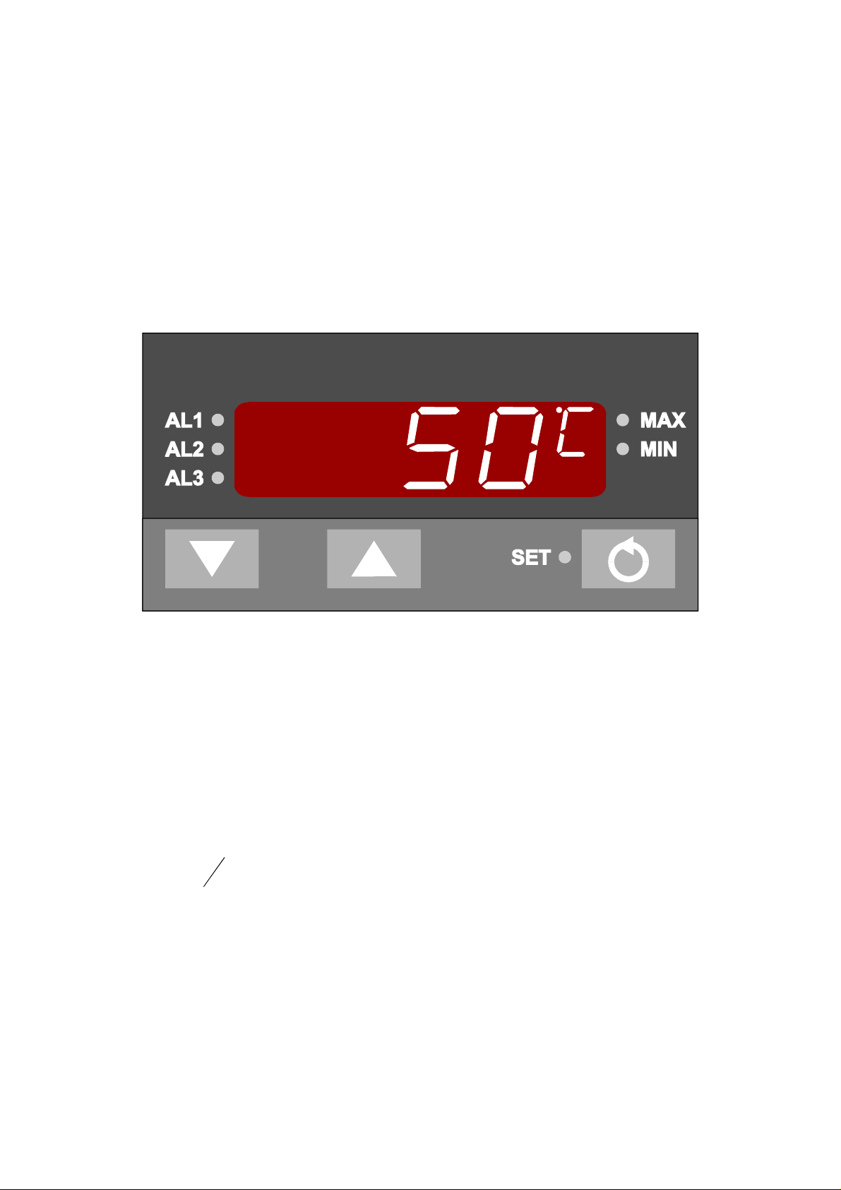
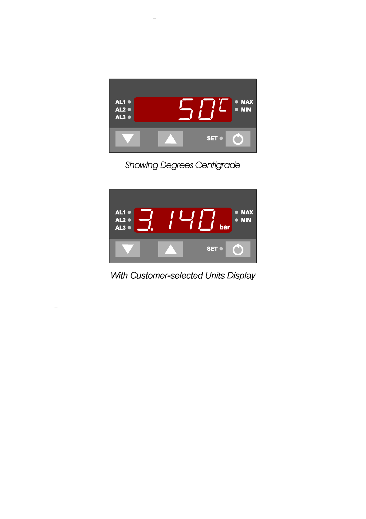
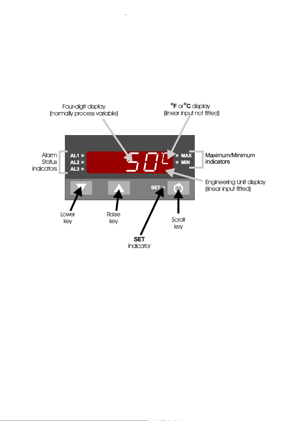
The Operator Mode is the normal mode of the Indicator, once it has been set up and
configured as required. The front panel displays, indicators and keys are shown in
Figure 2-1.
Fig ure 2-1 Front Panel Con trols, Dis plays and In di ca tors
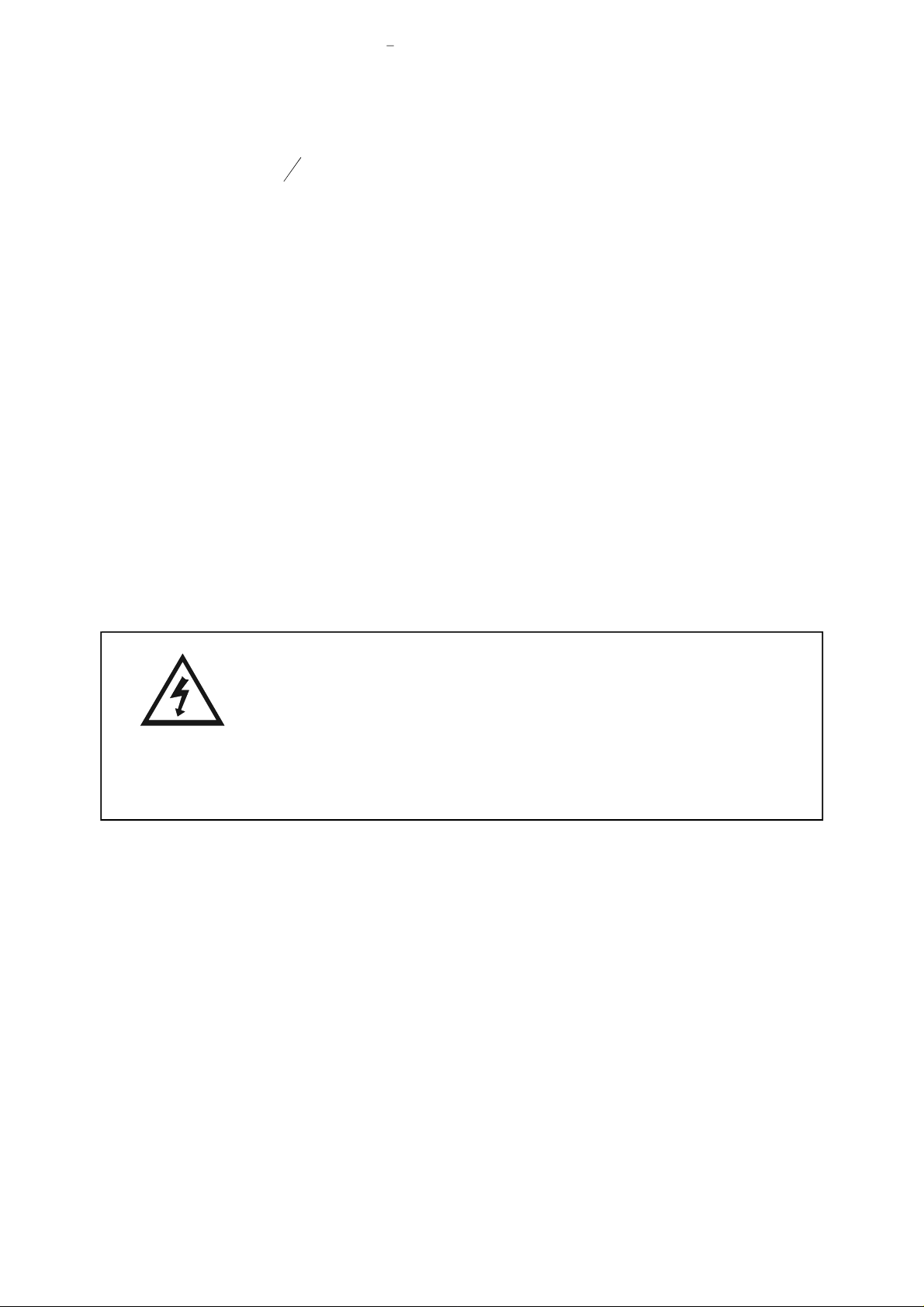
2.2 FOUR-DIGIT DISPLAY
In Operator Mode, this normally displays the process variable value. Using the Scroll
key, the operator may view, in a sequence according to the Operator Mode Display
Strategy parameter in Set Up Mode (see NOTES ON TABLE 3-1):
(i) Cur rent maxi mum value at tained by pro cess vari able (since the maxi mum
value was last re set) - MAX in di ca tor ON when this is dis played. Also saves
the Sen sor Break (see Sub sec tion 2.6) and Over- Range (see Sub sec tion
2.5) con di tions.
(ii) Cur rent mini mum value at tained by pro cess vari able (since the mini mum
value was last re set) - MIN in di ca tor ON when this is dis played. Also saves
the Sen sor Break (see Sub sec tion 2.6) and Under- Range (see Sub sec tion
2.5) con di tions.
OM067-2 November, 2000 2-1
Page 8

Sec tion 2
Op era tor Mode Prod uct Man ual - Vol ume I
1
-DIN Digi tal In di ca tor 59039
8
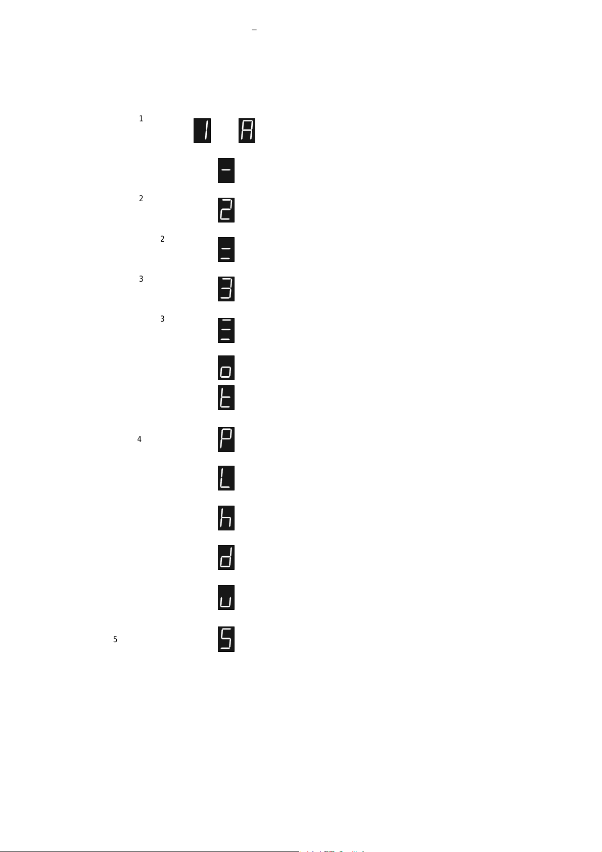
(iii) Time elapsed in the Alarm 1 ac tive con di tion (units dis play shows ).
The dis play is in the for mat mm.ss [mm = min utes, ss = sec onds] or mmm.s
[mmm = min utes, s = sec onds (tens)]. If elapsed time is greater than 999 min utes 59 sec onds, dis play will show:
NOTE: This does not in clude time when Alarm 1 is latched but alarm con di tion is cleared
(iv) Alarm 1 value (units dis play shows or, if only Alarm 1 pres ent, ).
(v) Alarm 2 value, if fit ted and con fig ured (units dis play shows ).
(vi) Alarm 3 value, if fit ted and con fig ured (units dis play shows ).
(iv) Proc ess vari able value.
Further depressions of the Scroll key will repeat this display sequence.
2.3 ALARM STATUS INDICATORS
The Alarm Status indicators show the current state of the alarm(s):
AL1 - Flashes when Alarm 1 is ac tive (with latch ing alarm, ON when
Alarm 1 is latched but alarm con di tion has cleared)
AL2 - Flashes when Alarm 2 is ac tive
AL3 - Flashes when Alarm 3 is ac tive
For descriptions of the operation of the various types of alarm available, see Section 3.
2.4 RESETTING THE MAXIMUM VALUE/MINIMUM VALUE OR TIME ELAPSED
VALUE
To reset the maximum value, minimum value (to the process variable value at the
instant of resetting) or time elapsed value (to zero):
1. Se lect the dis play of the maxi mum value, mini mum value or time
elapsed value (as ap pro pri ate - see above).
2. De press the Raise key or Lower key for three sec onds.
The resetting of the value is indicated by the four-digit display showing:
for two sec onds be fore re vert ing to the maxi mum value or mini mum value dis play.
2 -2 November, 2000 OM067-2
Page 9

59039
1
-DIN Digi tal In di ca tor Sec tion 2
8
Prod uct Man ual - Vol ume I Op era tor Mode
2.5 OVER-RANGE/UNDER-RANGE DISPLAYS
If the process variable attains a value higher than the input scale maximum limit
(over-range) or lower than the input scale minimum limit (under-range), the upper
display will show:
for the over-range condition and:
for the under-range condition.
2.6 SENSOR BREAK INDICATION
If a break is detected in the sensor circuit, the four-digit display will show:
The reaction of the alarms to a detected sensor break is dependent upon the input type.
2.7 COLD JUNCTION COMPENSATION DISABLED
If a thermocouple input is fitted, the Cold Junction Compensation should
be enabled. If it is disabled, whenever the process variable is displayed,
the unit display will be as shown on the right.
2.8 RESETTING THE LATCHED ALARM
If Output 1 is configured to be a latched alarm output, once it becomes active it will
remain active (even if the alarm condition itself is cleared) until reset either from the
front panel or via the Remote Reset hardware option. To reset the latched alarm from
the front panel:
1. En sure that the nor mal Op er at ing Mode dis play (i.e. pro cess vari able)
is shown.
2. Press ei ther the Raise key or the Lower key for at least three sec onds.
The four-digit display will then show:
OM067-2 November, 2000 2-3
Page 10

Sec tion 2
Op era tor Mode Prod uct Man ual - Vol ume I
1
-DIN Digi tal In di ca tor 59039
8
for two seconds, indicating that the latched alarm has been reset. The latched Alarm 1
can be reset only if the original alarm condition has been cleared; this reset has no
effect whilst the alarm condition prevails.
2.9 VIEWING THE HARDWARE DEFINITION CODE
The operator may view the current Hardware Definition Code setting in the four-digit
display by simultaneously depressing the Lower and Scroll keys. A return may be made
to the normal Operator Mode display by simultaneously depressing the Lower and
Scroll keys.
NOTE: An automatic return is made to the normal Operator Mode
display after 30 seconds.
To view the Hardware Option setting, press the Scroll key whilst the Hardware
Definition Code is displayed. To return to the Hardware Definition Code display,
depress the Lower and Scroll keys simultaneously.
2-4 November, 2000 OM067-2
Page 11

59039
1
-DIN Digi tal In di ca tor Sec tion 3
8
Prod uct Man ual - Vol ume I Set Up Mode
SEC TION 3
SET UP MODE
3.1 ENTRY INTO SET UP MODE
To enter Set Up Mode, with the instrument initially in Operator Mode displaying the
process variable value, depress the Raise and Scroll keys simultaneously for three
seconds. The instrument will then enter Set Up Mode and the SET indicator will come
ON, the instrument still displaying the process variable value.
NOTE: If the four-digit display shows:
(i.e. all decimal point positions illuminated), this indicates that one or
more of the critical Configuration Mode parameters - typically input
range - have been altered in value/setting and, as a consequence, all
Set Up Mode parameters have been automatically set to their default
values/settings. To clear this display, simply alter the value/setting of
any Set Up Mode parameter (see below).
The pa rame ters avail able for view/ad just ment in Set Up Mode are sum ma rised in Ta ble
3-1. When Set Up Mode is ac tive, the units dis play (nor mally oF, oC or blank) will show
the single- character leg end for the se lected pa rame ter and the value for that pa rame ter
will be shown in the four- digit dis play. The user may step through the Set Up Mode
pa rame ters by de press ing the Scroll key. The value/set ting may be al tered us ing the
Raise/Lower keys.
OM067-3 November, 2000 3-1
Page 12
Sec tion 3
1
-DIN Digi tal In di ca tor 59039
8
Set Up Mode Prod uct Man ual - Vol ume I
Table 3-1 Set Up Pa rame ters
Parameter
Alarm 1 Value
1
Alarm 1 Hysteresis
Alarm 2 Value
Alarm 2 Hysteresis
Alarm 3 Value
Alarm 3 Hysteresis
2
2
3
3
Process Variable Offset
Digital Filter Time Const.
Legend
or
Adjustment Range
Range Min. to Range Max.
1 LSD to 10% of span expressed
as display units
Range Min. to Range Max.
1 LSD to 10% of span expressed
as display units
Range Min. to Range Max.
1 LSD to 10% of span expressed
as display units
input span of instrument
0.0 secs. (OFF) to 100.0 secs. in
0.5 sec. increments.
Default
Range Max. (Proc. High)
Range Min. (Proc. Low)
1 LSD
Range Max. (Proc. High)
Range Min. (Proc. Low)
1 LSD
Range Max. (Proc. High)
Range Min. (Proc. Low)
1 LSD
0
2.0 secs.
Linear Input Decimal
Point Position
Linear Input Scale
Range Minimum
Linear Input Scale
Range Maximum
4
4
4
Recorder Output Scale
Minimum
Recorder Output Scale
Maximum
Operator Mode Display
Strategy
5
0 (XXXX), 1 (XXX.X), 2 (XX.XX)
or 3 (X.XXX)
–1999 to 9999
–1999 to 9999
–1999 to 9999
–1999 to 9999
0, 1, 2, 3 or 4
1
0000
1000
Range Min.
Range Max.
0
3-2 November, 2000 OM067-3
Page 13
59039
1. The legend for this parameter will be if only Alarm 1 is fitted/configured or if o ther
alarms are fitted/configured.
2. These parameters appear in the display sequence only if Alarm 2 is fitted/configured.
3. These parameters appear in the display sequence only if Alarm 3 is fitted/configured.
4. Only applicable if a DC Linear input is fitted.
5. Defines the parameters displayed in sequence in Operator Mode:
1
-DIN Digi tal In di ca tor Sec tion 3
8
Prod uct Man ual - Vol ume I Set Up Mode
NOTES ON TABLE 3-1
Parameter Setting
0
PV value
Max. PV value
Min. PV value
Elapsed Time
1
PV value
Max. PV value
Min. PV value
2
PV value
Alarm 1 value
Alarm 2 value *
Alarm 3 value *
* If configured/fitted
3
PV value
Max. PV value
Min. PV value
Alarm 1 value
Alarm 2 value *
Alarm 3 value *
4
PV value
Max. PV value
Min. PV value
Elapsed Time
Alarm 1 value
Alarm 2 value *
Alarm 3 value
3.2 ALAR M 1 VALUE or
If Alarm 1 is selected to be a Process High alarm, this defines the process variable
value at or above which Alarm 1 will be active; the default value will be Input Range
Maximum. If Alarm 1 is selected to be a Process Low alarm, this defines the process
variable value at or below which Alarm 1 will be active; the default value will be Input
Range Minimum. Its value may be adjusted between Input Range Maximum and Input
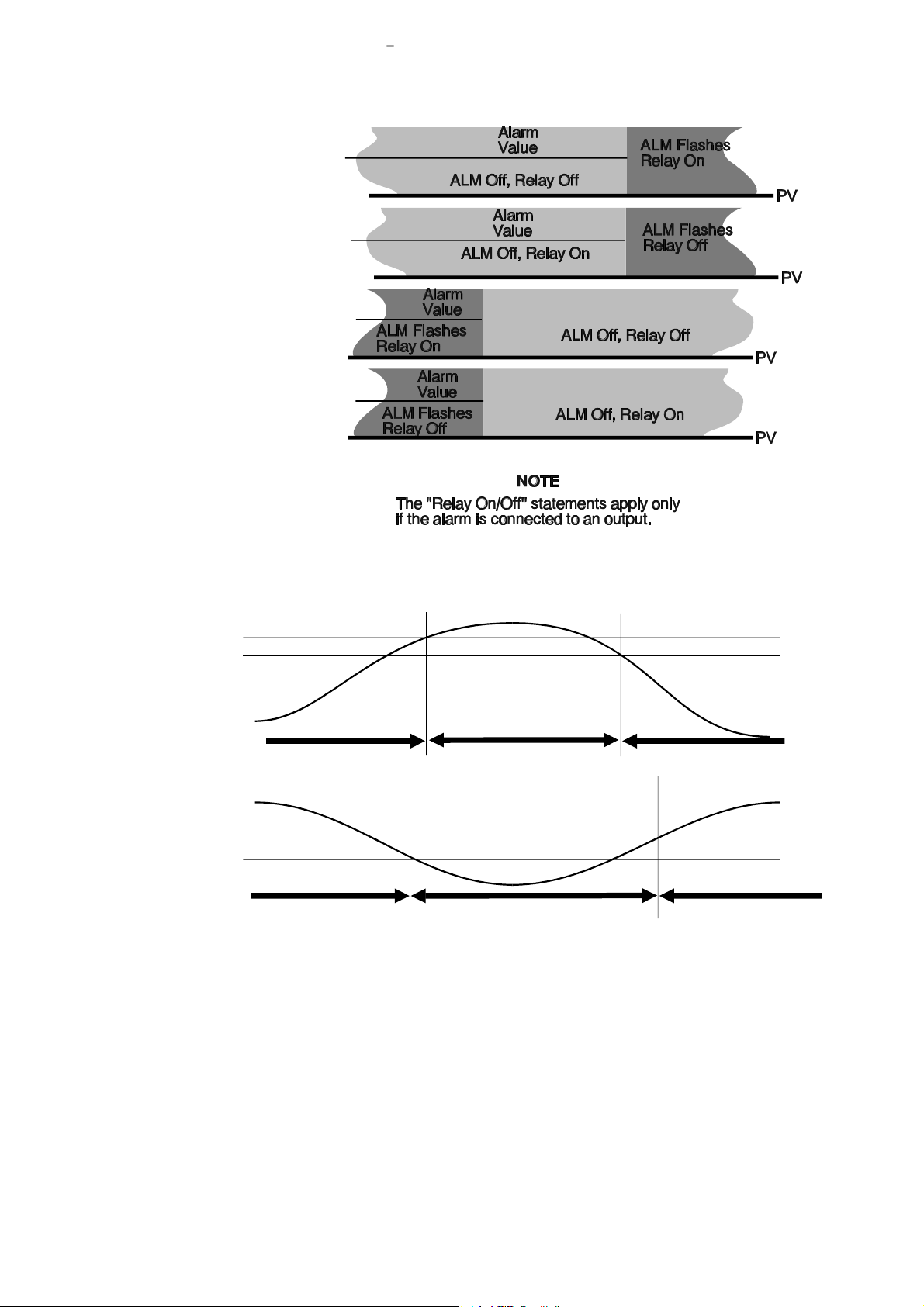
Range Minimum. Alarm operation is illustrated in Figure 3-1.
3.3 ALARM 1 HYSTERESIS
This parameter applies a hysteresis band on the “safe” side of the Alarm 1 value. The
effect of the hysteresis value on alarm operation is shown in Figure 3-2.
3.4 ALARM 2 VALUE
If Alarm 2 is selected to be a Process High alarm, this defines the process variable
value at or above which Alarm 2 will be active; the default value will be Input Range
Maximum. If Alarm 2 is selected to be a Process Low alarm, this defines the process
variable value at or below which Alarm 2 will be active; the default value will be Input
Range Minimum. Its value may be adjusted between Input Range Maximum and Input
Range Minimum. Alarm operation is illustrated in Figure 3-1.
3.5 ALARM 2 HYSTERESIS
This parameter applies a hysteresis band on the “safe” side of the Alarm 2 value. The
effect of the hysteresis value on alarm operation is shown in Figure 3-2.
OM067-3 November, 2000 3-3
Page 14

Sec tion 3
Set Up Mode Prod uct Man ual - Vol ume I
1
-DIN Digi tal In di ca tor 59039
8
3.6 ALARM 3 VALUE
If Alarm 3 is selected to be a Process High alarm, this defines the process variable
value at or above which Alarm 3 will be active; the default value will be Input Range
Maximum. If Alarm 3 is selected to be a Process Low alarm, this defines the process
variable value at or below which Alarm 3 will be active; the default value will be Input
Range Minimum. Its value may be adjusted between Input Range Maximum and Input
Range Minimum. Alarm operation is illustrated in Figure 3-1.
3.7 ALARM 3 HYSTERESIS
This parameter applies a hysteresis band on the “safe” side of the Alarm 3 value. The
effect of the hysteresis value on alarm operation is shown in Figure 3-2.
3.8 PROCESS VARIABLE OFFSET
This parameter is used to modify the actual process variable value (measured at the
input terminals) in the following manner:
Offset PV value = Actual PV value + Process Variable Offset value.
The offset process variable value is used for all PV-dependent functions (display,
alarm, recorder output).
CAU TION: This is, in ef fect, a cali bra tion ad just ment. In ju di cious ap pli ca tion
of val ues to this pa rame ter could lead to the dis played pro cess vari able value
bear ing no mean ing ful re la tion ship to the ac tual pro cess vari able value.
There is no front panel in di ca tion when this pa rame ter is in ef fect (i.e.
has been set to a non- zero value).
The default value is 0.
3.9 INPUT FILTER TIME CONSTANT
The input is equipped with a digital filter which is used to filter out any extraneous
impulses on the process variable. This filtered PV is used for all PV-dependent
functions (alarms etc.). The time constant for this filter may be adjusted in the range 0.0
seconds (filter OFF) to 100.0 seconds in 0.5 second increments. The default setting is
2.0 seconds.
CAUTION: If this parameter is set excessively high, the indication
quality may be significantly impaired. The value chosen should be
sufficiently large to attenuate stray noise but no larger.
3.10 LINEAR INPUT SCALE RANGE MINIMUM
This parameter, applicable only if a linear input is fitted, defines the scaled input value
when the process variable input is at its minimum value. It is adjustable between –1999
and 9999 (with decimal point as defined by Linear Input Decimal Point Position). The
default value is 0. This parameter can be set to a value greater than (but not equal to)
Linear Input Scale Range Maximum, in which case the sense of the input is reversed.
3-4 November, 2000 OM067-3
Page 15

59039
1
-DIN Digi tal In di ca tor Sec tion 3
8
Prod uct Man ual - Vol ume I Set Up Mode
3.11 LINEAR INPUT SCALE RANGE MAXIMUM
This parameter, applicable only if a linear input is fitted, defines the scaled input value
when the process variable input is at its maximum value. It is adjustable between –1999
and 9999 (with decimal point as defined by Linear Input Decimal Point Position). The
default value is 1000. This parameter can be set to a value less than (but not equal to)
Linear Input Scale Range Minimum, in which case the sense of the input is reversed.
3.12 RECORDER OUTPUT SCALE MINIMUM
This parameter defines the value of the process variable at which the Recorder Output
reaches its minimum value; for example, for a 0 - 5V Recorder Output, this value
corresponds to 0V. It may be adjusted within the range –1999 to 9999. The decimal
point position for the Recorder Output is always the same as that for the process
variable input range. The default value is Input Range Minimum. This parameter is not
applicable if the Recorder Output option is not fitted.
NOTE: If this parameter is set to a value greater than that for the Recorder Output Scale Maximum (see Subsection 3.13), the relationship between the process variable value and the Recorder Output is reversed.
3.13 RECORDER OUTPUT SCALE MAXIMUM
This parameter defines the value of process variable at which the Recorder Output
reaches its maximum value; for example, for a 0 - 5V Recorder Output, this value
corresponds to 5V. It may be adjusted within the range –1999 to 9999. The decimal
point position for the Recorder Output is always the same as that for the process
variable input range. The default value is Input Range Maximum. This parameter is not
applicable if the Recorder Output option is not fitted.
NOTE: If this parameter is set to a value less than that for the Recorder
Output Scale Minimum (see Subsection 3.12), the relationship
between the process variable/setpoint value and the Recorder Output
is reversed.
3.14 OPERATOR MODE DISPLAY STRATEGY
This defines the sequence of parameter displays available in Operator Mode (see
NOTES ON TABLE 3-1).
3.15 EXIT FROM SET UP MODE
To leave Set Up Mode, select the initial Operator Mode display (process variable value)
then depress the Raise and Scroll keys simultaneously, whereupon the SET indicator
will go OFF and the instrument will return to Operator Mode.
NOTE: An automatic return to Operator mode will be executed if there
is no key activity in Set Up Mode for one minute.
OM067-3 November, 2000 3-5
Page 16
Sec tion 3
Set Up Mode Prod uct Man ual - Vol ume I
1
-DIN Digi tal In di ca tor 59039
8
Process High Alarm
direct-acting
Process High Alarm
reverse-acting
Process Low Alarm
direct-acting
Process Low Alarm
reverse-acting
PROCESS
HIGH
ALARM
PROCESS
LOW
ALARM
Figure 3-1 Alarm Op era tion
Alarm Hysteresis
Alarm Inactive
Process Variable
Alarm Hysteresis
Alarm Inactive
Alarm Active
Figure 3-2 Alarm Hys tere sis Op era tion
Alarm Value
Process Variable
Alarm Inactive
Alarm Value
Alarm InactiveAlarm Active
3-6 November, 2000 OM067-3
Page 17

59039
1
-DIN Digi tal In di ca tor Sec tion 4
8
Product Man ual - Vol ume I RS485 Se rial Com mu ni ca tions
SEC TION 4
RS485 SERIAL COMMUNICATIONS
This three-wire RS485-compatible serial communications option is the means by which
communication may occur between the instrument and a master device (e.g. a
computer or terminal).
4.1 PHYSICAL REQUIREMENTS
There are two communications protocols available with this option:
(a) AS CII
(b) MOD BUS
4.1.1 Char ac ter Trans mis sion
Data format is fixed to be seven data bits and one stop bit. The Baud rate may be
selected to be 1200, 2400, 4800 (default) or 9600 Baud. For ASCII protocol, the parity
is even. For MODBUS protocol, the parity is selectable to be even, odd or none.
4.1.2 Line Turn- Round
AS CII Pro to col: The com mu ni ca tions link is op er ated as a multi- drop half
du plex sys tem. When a de vice is trans mit ting, it drives the trans mis sion lines
to the ap pro pri ate lev els; when it is not trans mit ting, its out puts are set to a
high im ped ance in or der that an other de vice can trans mit. It is im por tant that
a trans mit ter re leases the trans mis sion lines be fore an other de vice starts
trans mis sion. This im poses the fol low ing re straints on the mas ter de vice:
(a) The transmitter must release the transmission lines within 6ms of
the end of the last character of a message being transmitted. Note that
delays due to buffers such as those used in universal asynchronous
receivers/transmitters (UARTs) within the master device must be taken
into account.
(b) The transmitter must not start transmission until 6ms has elapsed
since the reception of the last character of a message.
All in stru ments in this range hav ing an RS485 com mu ni ca tions fa cil ity ad here to this stan dard; thus, pro vided that the mas ter de vice con forms simi larly to the stan dard, there should be no line con ten tion prob lems.
MOD BUS Pro to col: The line turn- round tim ings ad here to the in dus try stan dard.
4.2 ASCII PROTOCOL
This protocol assumes half duplex communications. All communication is initiated by
the master device. The master sends a command or query to the addressed slave and
the slave replies with an acknowledgement of the command or the reply to the query.
All messages, in either direction, comprise:
OM067-4 November, 2000 4-1
Page 18

Sec tion 4
RS485 Se rial Com mu ni ca tions Product Man ual - Vol ume I
1
-DIN Digi tal In di ca tor 59039
8
(a) A Start of Message character
(b) One or two address characters (uniquely defining the slave)
(c) A parameter/data character string
(d) An End of Message character
Messages from the master device may be one of four types:
Type 1: L {N} ? ? *
Type 2: L {N} {P} {C} *
Type 3: L {N} {P} # {DATA} *
Type 4: L {N} {P} I *
where all characters are in ASCII code and:
L is the Start of Mes sage char ac ter (Hex 4C)
{N} is the slave ad dress (in the range 1 - 32); ad dresses 1 - 9
may be rep re sented by a sin gle digit (e.g. 7) or in two- digit
form, the first digit be ing zero (e.g. 07).
{P} is a char ac ter which iden ti fies the pa rame ter to be in ter ro -
gated/modi fied - see Ta ble 4-2.
{C} is the com mand (see be low)
# in di cates that {DATA} is to fol low (Hex 23)
{DATA} is a string of nu meri cal data in AS CII code (see Ta ble 4-1)
* is the End of Mes sage char ac ter (Hex 2A)
No space char ac ters are per mit ted in mes sages. Any syn tax er rors in a re ceived
mes sage will cause the slave to is sue no re ply and await the Start of Mes sage
char ac ter.
4-2 November, 2000 OM067-4
Page 19

59039
1
-DIN Digi tal In di ca tor Sec tion 4
8
Product Man ual - Vol ume I RS485 Se rial Com mu ni ca tions
Table 4-1 {DATA} Ele ment - Sign and Deci mal Point Po si tion
Identifier
Character
A
B
C
D
E
F
G
H
J
L
M
N
O
Q
T
Z
[
\
]
m
{DATA} Content
abcd0
abcd1
abcd2
abcd3
abcd5
abcd6
abcd7
abcd8
Sign/Decimal Point Position
+abcd
+abc.d
+ab.cd
+a.bcd
–abcd
–abc.d
–ab.cd
–a.bcd
Table 4-2 Com mands/Pa rame ters and Iden ti fi ers
Parameter/Command
Maximum Process Variable value
Minimum Process Variable value
Alarm 1 value
Alarm 1 Hysteresis value
Alarm 2 value
Alarm 2 Hysteresis value
1
1
Scale Range Maximum
Read Only
Read Only
Read/Write
Read/Write
Read/Write
Read/Write
Read/Write (linear inputs
only) - otherwise Read Only
Scale Range Minimum
Read/Write (linear inputs
only) - otherwise Read Only
Process Variable Offset value
Instrument Status
2
Process Variable value
Alarm 3 value
Alarm 3 Hysteresis
3
3
Scale Range Decimal Point Position
Read/Write
Read Only
Read Only
Read/Write
Read/Write
Read/Write (linear inputs
only) - otherwise Read Only
Time Elapsed
Instrument Commands
4
Recorder Output Scale Maximum
Recorder Output Scale Minimum
Scan Table
6
Input Filter Time Constant value
5
5
Read Only
Write Only
Read/Write
Read/Write
Read Only
Read/Write
Operation
NOTES
1. Applicable only if Alarm 2 is configured.
2. See Subsection 4.3.15.
3. Applicable only if Alarm 3 is configured.
4. See Subsection 4.3.16.
5. Applicable only if Output 2 is configured as a Recorder Output.
6. See Subsection 4.3.17.
OM067-4 November, 2000 4-3
Page 20

Sec tion 4
RS485 Se rial Com mu ni ca tions Product Man ual - Vol ume I
1
-DIN Digi tal In di ca tor 59039
8
4.2.1 Type 1 Mes sage
L {N} ? ? *
This message is used by the master device to determine whether the addressed slave
is active. The reply from the slave instrument, if it is active, is
L {N} ? A *
An inactive instrument will give no reply.
4.2.2 Type 2 Mes sage
L {N} {P} {C} *
This type of message is used by the master device to interrogate or modify a parameter
in the addressed instrument. {P} identifies the parameter (as defined in Table 4-2) and
{C} represents the command to be executed, which may be one of the following:
+ (Hex 2B) - In cre ment the value of the pa rame ter de fined by {P}
– (Hex 2D) - Dec re ment the value of the pa rame ter de fined by {P}
? (Hex 3F) - De ter mine the cur rent value of the pa rame ter de fined by {P}
The reply from the addressed instrument is of the form:
L {N} {P} {DATA} A *
where {DATA} comprises five ASCII-coded digits whose format is shown in Table 4-1.
The data is the value requested in a query message or the new value of the parameter
after modification. If the action requested by the message from the master device would
result in an invalid value for that parameter (either because the requested new value
would be outside the permitted range for that parameter or because the parameter is
not modifiable), the instrument replies with a negative acknowledgement:
L {N} {P} {DATA} N *
The {DATA} string in the negative acknowledgement reply will be indeterminate.
Scan Tables
A parameter identifier character “]” in the message from the master device indicates
that a “Scan Table” operation is required. This provides a facility for interrogating the
values of a group of parameters and status in a single message from the master
device. The reply to such a command would be in the form:
L {N} ] 25 aaaaa bbbbb ccccc ddddd eeeee A *
The digits aaaaa, bbbbb etc. are expressed as shown in Table 4-1. For further
information, refer to Subsection 4.3.17.
4.2.3 Type 3 Mes sage
L {N} {P} # {DATA} *
This message type is used by the master device to set a parameter to the value
specified in {DATA}. The command is not implemented immediately by the slave
instrument; the slave will receive this command and will then wait for a Type 4 message
(see below). Upon receipt of a Type 3 message, if the {DATA} content and the specified
parameter are valid, the slave reply is of the form:
4-4 November, 2000 OM067-4
Page 21

59039
1
-DIN Digi tal In di ca tor Sec tion 4
8
Product Man ual - Vol ume I RS485 Se rial Com mu ni ca tions
L {N} {P} {DATA} I *
(where I = Hex 49) indicating that the instrument is ready to implement the command. If
the parameter specified is invalid or is not modifiable or if the desired value is outside
the permitted range for that parameter, the instrument replies with a negative
acknowledgement in the form:
L {N} {P} {DATA} N *
4.2.4 Type 4 Mes sage
L {N} {P} I *
This type of message is sent by the master device to the addressed slave following a
successful Type 3 message transmission and reply to/from the same slave instrument.
Provided that the {DATA} content and the parameter specified in the preceding Type 3
message are still valid, the slave will then set the parameter to the desired value and
will reply in the form:
L {N} {P} {DATA} A *
where {DATA} is the new value of the parameter. If the new value or parameter
specified is invalid, the slave will reply with a negative acknowledgement in the form:
L {N} {P} {DATA} N *
where {DATA} is indeterminate. If the immediately-preceding message received by the
slave was not a Type 3 message, the Type 4 message is ignored.
4.3 INDIVIDUAL PARAMETERS
The individual parameters and how they may be interrogated/modified are described
below. Unless otherwise stated, the {DATA} element will follow the standard five-digit
format and the decimal point position must be correct for the new value to be accepted
and for modification to occur.
NOTE: The communications identifier character {P} for each
parameter is shown to the right of each subsection heading.
4.3.1 Proc ess Vari able {P} = M
This parameter may be interrogated only, using a Type 2 message. If the process
variable is out of range, the five-digit {DATA} field in the reply will not contain a number,
but will contain <??>0 (over-range) or <??>5 (under-range).
4.3.2 Proc ess Vari able Off set {P} = J
This parameter may be modified/interrogated using a Type 2 message or a Type 3/4
message sequence. It modifies the actual process variable value (as measured at the
instrument’s input terminals) in the following manner:
Modified PV value = Actual PV value + process variable offset value
The modified PV value is limited by Range Maximum and Range Minimum and is used
for display and alarm purposes and for recorder outputs.
OM067-4 November, 2000 4-5
Page 22

Sec tion 4
RS485 Se rial Com mu ni ca tions Product Man ual - Vol ume I
1
-DIN Digi tal In di ca tor 59039
8
NOTE: This parameter value should be selected with care. Any
adjustment to this parameter is, in effect, an adjustment to the
instrument’s calibration. Injudicious application of values to this
parameter could lead to the displayed PV value having no meaningful
relationship to the actual PV value.
4.3.3 Scale Range Maxi mum {P} = G
This parameter (which is adjustable only on DC linear inputs) may be interrogated using
a Type 2 message or may be modified using a Type 3/4 message sequence. The
decimal point position is as for the input range.
4.3.4 Scale Range Mini mum {P} = H
This parameter (which is adjustable only on DC linear inputs) may be interrogated using
a Type 2 message or may be modified using a Type 3/4 message sequence. The
decimal point position is as for the input range.
4.3.5 Scale Range Deci mal Point Po si tion {P} = Q
Adjustable on DC linear inputs only, this parameter may be modified/interrogated using
a Type 2 message or a Type 3/4 message sequence. The value of this parameter
defines the decimal point position, as follows:
Value
0
1
2
3
Decimal Point Position
abcd
abc.d
ab.cd
a.bcd
4.3.6 In put Fil ter Time Con stant
{P} = m
This parameter may be modified/interrogated using a Type 2 message or a Type 3/4
message sequence.
4.3.7 Re corder Out put Scale Maxi mum Value {P} = [
This parameter may be modified/interrogated using a Type 2 message or a Type 3/4
message sequence. It defines the maximum scale value for the Controller’s Recorder
Output and may be adjusted within the range –1999 to 9999. This value corresponds to
the Input Scale Maximum and the decimal point position will always be the same as
that for the input.
NOTE: If this parameter is set to a value less than the Recorder Output
Minimum Value, the sense of the Recorder Output is reversed.
4.3.8 Re corder Out put Scale Mini mum Value {P} = \
This parameter may be modified/interrogated using a Type 2 message or a Type 3/4
message sequence. It defines the minimum scale value for the Controller’s Recorder
Output and may be adjusted within the range –1999 to 9999. This value corresponds to
4-6 November, 2000 OM067-4
Page 23

59039
1
-DIN Digi tal In di ca tor Sec tion 4
8
Product Man ual - Vol ume I RS485 Se rial Com mu ni ca tions
the Input Scale Minimum and the decimal point position will always be the same as that
for the input.
NOTE: If this parameter is set to a value greater than the Recorder
Output Maximum Value, the sense of the Recorder Output is reversed.
4.3.9 Alarm 1 Value {P} = C
This parameter may be modified/interrogated using a Type 2 message or a Type 3/4
message sequence. It defines the level at which Alarm 1 will go active. The decimal
point position is as for the input range.
4.3.10 Alarm 1 Hys tere sis Value {P} = D
This parameter may be modified/interrogated using a Type 2 message or a Type 3/4
message sequence. It defines the hysteresis band applied to the “safe” side of Alarm 1.
The decimal point position is as for the input range.
4.3.11 Alarm 2 Value {P} = E
This parameter may be modified/interrogated using a Type 2 message or a Type 3/4
message sequence. It defines the level at which Alarm 2 will go active. The decimal
point position is as for the input range.
4.3.12 Alarm 2 Hys tere sis Value {P} = F
This parameter may be modified/interrogated using a Type 2 message or a Type 3/4
message sequence. It defines the hysteresis band applied to the “safe” side of Alarm 2.
The decimal point position is as for the input range.
4.3.13 Alarm 3 Value {P} = N
This parameter may be modified/interrogated using a Type 2 message or a Type 3/4
message sequence. It defines the level at which Alarm 3 will go active. The decimal
point position is as for the input range.
4.3.14 Alarm 3 Hys tere sis Value {P} = O
This parameter may be modified/interrogated using a Type 2 message or a Type 3/4
message sequence. It defines the hysteresis band applied to the “safe” side of Alarm 3.
The decimal point position is as for the input range.
4.3.15 In stru ment Status {P} = L
This pa rame ter may be in ter ro gated only, us ing a Type 2 mes sage. The status
in for ma tion is en coded in the four dig its as the deci mal rep re sen ta tion of a bi nary
number. Each bit in the bi nary number has a par ticu lar sig nifi cance:
OM067-4 November, 2000 4-7
Page 24

Sec tion 4
RS485 Se rial Com mu ni ca tions Product Man ual - Vol ume I
1
-DIN Digi tal In di ca tor 59039
8
Bit 5: Alarm 1 Latched
(1 = not latched, 0 = latched)
If non-latching, fixed at 1.
Bit 3: Change Indicator (1 = A parameter other than
Instrument Status or Process Variable has been
changed via the front panel since the last time the
Status Byte was read; 0 = No change has occurred).
000 1
Bit 2: Alarm 3 Status
(0 = Active; 1 = Safe)
Bit 0: Alarm 1 Status
(0 = Active; 1 = Safe)
Bit 1: Alarm 2 Status
(0 = Active; 1 = Safe)
4.3.16 In stru ment Com mands {P} = Z
Only Type 3 or Type 4 messages are allowed with this parameter. In the Type 3
message, the {DATA} field must be one of four five-digit numbers. The reply from the
instrument also contains the {DATA} field with the same content. When the master
device issues the Type 4 message, the instrument responds with the same {DATA} field
content. The commands corresponding to the {DATA} field value are:
00150 = Unlatch Alarm 1 (returns NAK if Alarm 1 is non-latching)
00160 = Reset Process Variable Maximum (to current PV value)
00170 = Reset Process Variable Minimum (to current PV value)
00180 = Reset Time Elapsed (to zero)
4.3.17 Scan Ta ble {P} = ]
The Scan Table operation takes the form of a Type 2 interrogation command which
accesses a set of information (held in the {DATA} element in the response). The
response would be in the form:
L {N} ] 25 aaaaa bbbbb ccccc ddddd eeeee A *
These digits are as described in Table 4-1 and comprise:
aaaaa The cur rent pro cess vari able value
bbbbb The cur rent maxi mum pro cess vari able value
ccccc The cur rent mini mum pro cess vari able value
ddddd The cur rent Time El pased value
eeeee The In stru ment Status (see Sub sec tion 4.3.15).
4.3.18 Er ror Re sponse
The circumstances under which a message from the master device is ignored are:
Par ity er ror de tected
Syn tax er ror de tected
Ti me out elapsed
Re ceipt of a Type 4 mes sage with out a pre ced ing Type 3 com mand mes sage.
Nega tive ac know ledge ments will be re turned if, in spite of the re ceived mes sage be ing
no tion ally cor rect, the in stru ment can not sup ply the re quested in for ma tion or per form
the re quested op era tion. The {DATA} ele ment of a nega tive ac know ledge ment will be
in de ter mi nate.
4 -8 November, 2000 OM067-4
Page 25

59039
1
-DIN Digi tal In di ca tor Sec tion 4
8
Product Man ual - Vol ume I RS485 Se rial Com mu ni ca tions
4.4 MODBUS PROTOCOL
With the RS485 Serial Communication option fitted and configured, communication
between a master device and slave instruments via protocol conforming to the
MODBUS industry standard is available.
NOTE: Support for multi-parameter Write operations is limited to
support of the Multi-word Write Function (Number 16) but this permits
writing of one parameter value only per message.
The parameter numbering system divides the parameters into bits and words, each
group being numbered independently.
4.4.1 Bit Pa rame ters
There are up to 11 bit pa rame ters:
Parameter
Alarm 1 Status
Alarm 2 Status
Alarm 3 Status
Alarm 1 Latched
PV Under-range Flag
PV Over-range Flag
Sensor Break Active
Reset Latched Alarm
Reset PV Maximum
Reset PV Minimum
Reset Time Elapsed
* Always returns 0 if Alarm 1 not configured to be latching.
No.
1
2
3
4
5
6
7
8
9
10
11
Operation
Read Only
Read Only
Read Only
Read Only
Read Only
Read Only
Read Only
Write Only
Write Only
Write Only
Write Only
Notes
1 = Active
1 = Active
1 = Active
1 = Alarm 1 latched *
1 = Active
1 = Active
1 = Active
OM067-4 November, 2000 4-9
Page 26

Sec tion 4
RS485 Se rial Com mu ni ca tions Product Man ual - Vol ume I
1
-DIN Digi tal In di ca tor 59039
8
4.4.2 Word Pa rame ters
Parameter
Process Variable (PV)
PV Maximum
PV Minimum
Time Elapsed
Instrument Status
PV Offset
Alarm 1 value
Alarm 2 value
Alarm 3 value
Alarm 1 Hysteresis
Alarm 2 Hysteresis
Alarm 3 Hysteresis
Filter Time Constant
Decimal Point Position
Scale Range Min.
Scale Range Max.
Recorder Output
Scale Max.
Recorder Output
Scale Min.
Manufacturer ID
Equipment ID
No.
1
2
3
4
5
6
7
8
9
10
11
12
13
14
15
16
17
18
121
122
Operation
Read Only *
Read Only *
Read Only *
Read Only *
Read Only
Read/Write
Read/Write
Read/Write
Read/Write
Read/Write
Read/Write
Read/Write
Read/Write
Read/Write
Read/Write
Read/Write
Read/Write
Read/Write
Read Only
Read Only
Notes
Only if Alarm 2 is configured
Only if Alarm 3 is configured
Only if Alarm 2 is configured
Only if Alarm 3 is configured
Read Only for non-linear inputs
Read Only for non-linear inputs
Read Only for non-linear inputs
Only if Recorder Output is
configured
Only if Recorder Output is
configured
= 231 (representing “W1")
number 8010
* When the process variable is over-range or under-range or when a
sensor break condition occurs, the value returned is:
Condition Hex. Signed Unsigned
Over-range F700 –2304 63232
Under-range F600 –2560 62976
Sensor Break condition F800 –2048 63488
The PV Max. parameter will return the Over-range value or Sensor Break
value (as appropriate) if either condition has occurred since the PV Max.
parameter was last reset.
The PV Min. parameter will return the Under-range value or Sensor Break
value (as appropriate) if either condition has occurred since the PV Min.
parameter was last reset.
The Time Elapsed parameter will return the Over-range value if the
time exceeds 1000 minutes.
NOTE: All these parameters return signed values except Time Elapsed
(which is unsigned) and Instrument Status (in which Bits 0 - 6 of the
status byte return Bit Parameters 1 - 7 respectively - see Subsection 4.4.1)
4-10 November, 2000 OM067-4
Page 27

59039
1
-DIN Digi tal In di ca tor Ap pen dix A
8
Prod uct Man ual - Vol ume I Al pha beti cal In dex
Al pha beti cal In dex
A
AL1 Indicator
Function 2-2
AL2 Indicator
Function 2-2
AL3 Indicator
Function 2-2
Alarm Hysteresis
Alarm 1 3-3
Alarm 1 (adjusting - comms.)
4-7
Alarm 2 3-3
Alarm 2 (adjusting - comms.)
4-7
Alarm 3 3-4
Alarm 3 (adjusting - comms.)
4-7
Alarm Status Indicators
Functions 2-2
Alarm Value
Alarm 1 3-3
Alarm 1 (adjusting - comms.)
4-7
Alarm 1 Operator Mode display
2-2
Alarm 2 3-3
Alarm 2 (adjusting - comms.)
4-7
Alarm 2 Operator Mode display
2-2
Alarm 3 (adjusting - comms.)
4-7
Alarm 3 Operator Mode display
2-2
C
Cold Junction Compensation
Disabled, indication of 2-3
Communications
ASCII protocol 4-1
Baud rates 4-1
Data format 4-1
End of Message character
4-2
Line release time maximum
value 4-1
Line turn-round 4-1
Messsage types 4-2
MODBUS bit parameters4-9
MODBUS protocol 4-9
MODBUS word parameters
4-10
Parity (ASCII protocol) 4-1
Parity (MODBUS protocol)
4-1
Scan Tables command 4-4
Start of Message character
4-2
Type 1 message 4-4
Type 2 message 4-4
Type 3 message 4-4
Alarm 3 3-4
OM067-A November, 2000 A-1
Type 4 message 4-5
Page 28

Ap pen dix A
Al pha beti cal In dex Prod uct Man ual - Vol ume I
1
-DIN Digi tal In di ca tor 59039
8
Communications Message Format
4-1
D
Display Strategy (Operator Mode)
3-5
E
Error Responses 4-8
H
Hardware Definition Code
Viewing in Operator Mode
2-4
Hardware Option
Viewing in Operator Mode
2-4
I
Input Filter Time Constant 3-4
Adjusting (comms.) 4-6
Input Over-range Display 2-3
Input Under-range Display 2-3
Scale range maximum (adjusting
- comms.) 4-6
Scale range minimum 3-4
Scale range minimum (adjusting
- comms.) 4-6
P
Process Variable
Interrogating (comms.) 4-5
Operator Mode display 2-1 -
2-2
Process Variable Maximum
Operator Mode display 2-1
Resetting (from front panel)
2-2
Resetting (via comms. link)
4-8
Process Variable Minimum
Operator Mode display 2-1
Resetting (from front panel)
2-2
Instrument Commands 4-8
Instrument Status 4-7
L
Latched Alarm
Resetting (from front panel)
2-3
Resetting (via comms. link)
4-8
Linear Input
Reversing sense of3-4 - 3-5
Scale Range Decimal Point
Position 4-6
Scale range maximum 3-5
Resetting (via comms. link)
4-8
Process Variable Offset 3-4
Adjusting (comms.) 4-5
R
Recorder Output
Reversing sense of3-5 - 4-7
Scale maximum 3-5
Scale Maximum Value (adjusting
- comms.) 4-6
Scale minimum 3-5
Scale Minimum Value (adjusting
- comms.) 4-6
S
A-2 November, 2000 OM067-A
Page 29

59039
Scan Tables Command 4-8
Sensor Break Indication
Operator Mode 2-3
Set Up Mode
Automatic exit from 3-5
Entry into 3-1
Exit from 3-5
Set Up Parameters All At default
Indication of 3-1
T
Time Elapsed
1
-DIN Digi tal In di ca tor Ap pen dix A
8
Prod uct Man ual - Vol ume I Al pha beti cal In dex
Operator Mode display 2-2
Resetting (from front panel)
2-2
Resetting (via comms. link)
4-8
OM067-A November, 2000 A-3
Page 30

Ap pen dix A
1
-DIN Digi tal In di ca tor 59039
8
Al pha beti cal In dex Prod uct Man ual - Vol ume I
A-4 November, 2000 OM067-A
Page 31

59039
1
-DIN Digi tal In di ca tor
8
Prod uct Man ual - Vol ume II
1
-DIN DIGITAL INDICATOR
8
PRODUCT MANUAL
VOLUME II
INSTALLATION AND
CONFIGURATION INSTRUCTIONS
The procedures described in this volume must be
undertaken by technically competent servicing personnel.
SM067- V2 November, 2000 (i)
Page 32

1
-DIN Digi tal In di ca tor 59039
8
Prod uct Man ual - Vol ume II
Con tents
1 IN STAL LA TION 1-1
2 IN TER NAL LINKS AND SWITCHES 2-1
3 CON FIGU RA TION MODE 3-1
Ap pen di ces
A PROD UCT SPECI FI CA TION A-1
B AL PHA BETI CAL IN DEX B-1
(ii) November, 2000 SM067- V2
Page 33

59039
1
-DIN Digi tal In di ca tor Sec tion 1
8
Prod uct Man ual - Vol ume II In stal la tion
SEC TION 1
INSTALLATION
1.1 UNPACKING PROCEDURE
1. Remove the instrument from its packing. The instrument is supplied with a
panel gasket and push-fit fixing strap. Retain the packing for future use,
should it be necessary to transport the instrument to a different site or to
return it to the supplier for repair/testing.
2 . Examine the delivered items for damage or deficiencies. If any is found,
notify the carrier immediately.
1.2 PANEL-MOUNTING
The panel on which the instrument is to be mounted must be rigid and may be up to
6.0mm (0.25 inches) thick. The cut-out required for a single Digital Indicator is as
shown in Figure 1-1.
45mm
+0.5 - 0.0
92mm
+0.5 - 0.0
Figure 1-1 Cut- out Di men sions
The Digital Indicator is 100mm deep (measured from the rear face of the front panel).
The front panel is 48mm high and 96mm wide. When panel-mounted, the front panel
projects 10mm from the mounting panel. The main dimensions of the instrument are
shown in Figure 1-2.
SM067-1 November, 2000 1-1
Page 34

Sec tion 1
In stal la tion Prod uct Man ual - Vol ume II
1
-DIN Digi tal In di ca tor 59039
8
Fig ure 1-2 Main Di men sions
To panel-mount the instrument:
1 . Insert the rear of the housing through the cut-out (from the front of the
mounting panel) and hold the instrument lightly in position against the panel.
Ensure that the panel gasket is not distorted and that the instrument is
positioned squarely against the mounting panel. Apply pressure to the front
panel bezel only.
CAUTION: Do not remove the panel gasket, as this may result in
inadequate clamping of the instrument in the panel.
2 . Slide the fixing strap in place (see Figure 1-3) and push it forward until it is
firmly in contact with the rear face of the mounting panel (the tongues on the
strap should have engaged in matching rachet positions on the housing and
the fixing strap springs should be pushing firmly against the mounting panel
rear face).
Once the in stru ment is in stalled in its mount ing panel, it may be sub se quently re moved
from its hous ing, if nec es sary, as de scribed in Sub sec tion 2.1.
1 -2 November, 2000 SM067-1
Page 35

59039
1
-DIN Digi tal In di ca tor Sec tion 1
8
Prod uct Man ual - Vol ume II In stal la tion
Mounting panel
Front panel
Sealing gasket
Fixing strap
Tongues on fixing strap
engage in ratchet slots
on housing
Housing
TOP VIEW OF INSTRUMENT
Figure 1-3 Panel- Mounting
SM067-1 November, 2000 1-3
Page 36

Sec tion 1
In stal la tion Prod uct Man ual - Vol ume II
1
-DIN Digi tal In di ca tor 59039
8
1.3 CONNECTIONS AND WIRING
The rear terminal connections are illustrated in Figure 1-4.
Output 1 is always a relay output which may be used as Alarm 1 (latching or
non-latching) or the logical OR of Alarms 1 & 2.
Output 2 (option) may be a relay output (Alarm 2, Alarm 3 or logical OR of Alarms
1 & 2, 1 & 3 or 2 & 3) or a DC output (recorder output)
Output 3 (option) may be a relay output (Alarm 2, Alarm 3 or logical OR of Alarms
1 & 2, 1 & 3 or 2 & 3) or a transmitter power supply output
Figure 1-4 Rear Ter mi nal Con nec tions
1-4 November, 2000 SM067-1
Page 37

59039
1
-DIN Digi tal In di ca tor Sec tion 1
8
Prod uct Man ual - Vol ume II In stal la tion
1.3.1 Mains (Line) In put
The instrument will operate on 96 - 264V AC 50/60Hz mains (line) supply. The power
consumption is approximately 4 VA.
CAUTION: This equipment is designed for installation in an enclosure
which provides adequate protection against electric shock. Local
regulations regarding electrical installation should be rigidly observed.
Consideration should be given to prevention of access to the power
terminations by unauthorised personnel. Power should be connected
via a two-pole isolating switch (preferably situated near the equipment)
and a 1A fuse, as shown in Figure 1-5.
Figure 1-5 Mains (Line) Sup ply Con nec tions
If the instrument has relay outputs in which the contacts are to carry
mains (line) voltage, it is recommended that the relay contact mains
(line) supply should be switched and fused in a similar manner but
should be separate from the instrument mains (line) supply.
1.3.2 24V (Nomi nal) AC/DC Sup ply
The supply connections for the 24V AC/DC version are shown in Figure 1-6. Power
should be connected via a two-pole isolating switch and a 315mA slow-blow fuse
(anti-surge Type T).
Figure 1-6 24V AC/DC Sup ply Con nec tions
The nominal 24V supply may be in the following ranges:
24V (nomi nal) AC 50/60Hz - 20 - 50V
24V (nomi nal) DC - 22 - 65V
SM067-1 November, 2000 1-5
Page 38

Sec tion 1
1
-DIN Digi tal In di ca tor 59039
8
In stal la tion Prod uct Man ual - Vol ume II
Table 1-1 Ther mo cou ple Ca ble Col our Codes
1-6 November, 2000 SM067-1
Page 39

1
59039
-DIN Digi tal In di ca tor Sec tion 1
8
Prod uct Man ual - Vol ume II In stal la tion
1.3.3 Ther mo cou ple In put
The correct type of thermocouple extension leadwire/compensating cable must be used
for the entire distance between the instrument and the thermocouple, ensuring that
correct polarity is observed throughout. Joints in the cable should be avoided, if
possible. The CJC facility must be enabled (normal conditions) for this input (see
Subsection 3.10).
NOTE: Do not run thermocouple cables adjacent to power-carrying
conductors. If the wiring is run in a conduit, use a separate conduit for
the thermocouple wiring. If the thermocouple is grounded, this must be
done at one point only. If the thermocouple extension lead is shielded,
the shield must be grounded at one point only.
The colour codes used on thermocouple extension leads are shown in Table 1-1.
1.3.4 RTD In put
The compensating lead should be connected to Terminal 3. For two-wire RTD inputs,
Terminals 2 and 3 should be linked. The extension leads should be of copper and the
resistance of the wires connecting the resistance element should not exceed 5 ohms
per lead (the leads should be of equal length).
1.3.5 Lin ear In put
For linear mA input ranges, connection is made to Terminals 1 and 4 in the polarity
shown in Figure 1-4. For linear mV and V ranges, connection is made to Terminals 2
and 3 in the polarity shown in Figure 1-4. For details of the linear input ranges available,
refer to Appendix A. If it is required to display the engineering units used, refer to
Subsection 2.4.
1.3.6 Re mote Re set (Op tion)
With the Remote Reset option fitted, Terminals 16 and 17 may be connected to an
external switch/relay contacts or to a TTL-compatible logic signal, which is used to reset
the latched Alarm 1. For an external switch/relay contacts, an “open-closed” transition
will reset the latched alarm. For a TTL signal, a “Logic 1 - Logic 0" transition will reset
the latched alarm.
TTL lev els: Logic 1 >2.0V
Logic 0 <0.8V
NOTE: The Remote Reset option and the RS485 Serial
Communications option are mutually exclusive.
See also Subsection 3.3.2 and Appendix A.
1.3.7 Re lay Out put
The contacts are rated at 2A resistive at 120/240V AC.
1.3.8 DC Out put
See Appendix A.
SM067-1 November, 2000 1-7
Page 40

Sec tion 1
In stal la tion Prod uct Man ual - Vol ume II
1
-DIN Digi tal In di ca tor 59039
8
1.3.9 RS485 Se rial Com mu ni ca tions (Op tion)
The connections for the three-wire RS485 serial communications option (if fitted) are on
Terminals 16, 17 and 18, as shown in Figure 1-4. Where several instruments are
connected to one master port, the master port transceiver in the active state should be
capable of driving a load of 12kΩ per instrument; the master port transceiver in the
passive state must have pull-up/pull-down resistors of sufficiently low impedance to
ensure that it remains in the quiescent state whilst supplying up to ±100µA each to the
instrument’s transceivers in the high impedance state.
1 -8 November, 2000 SM067-1
Page 41

59039
1
-DIN Digi tal In di ca tor Sec tion 2
8
Prod uct Man ual - Vol ume II In ter nal Links and Switches
SEC TION 2
INTERNAL LINKS AND SWITCHES
2.1 REMOVING THE INSTRUMENT FROM ITS HOUSING
To withdraw the instrument from its housing, simply grip the side edges of the front
panel (there is a finger grip on each edge) and pull the instrument forwards. This will
release the instrument from its rear connectors in the housing and will give access to
the PCBs. Take note of the orientation of the instrument for subsequent replacement
into the housing.The positions of the PCBs in the instrument are shown in Figure 2-1.
Output 2 Link Jumpers
(DC Output only)
Top edge of
front panel
Power Supply PCB
CPU PCB
RS485 Serial Communications
Option PCB or
Remote Reset Option PCB
Input Link Jumpers
Output 2 Option PCB -
Relay Output (Alarm) or
DC Output (Recorder Output)
Output 3 Option PCB -
Relay Output (Alarm) or
Transmitter Power Supply
REAR VIEW OF UNHOUSED INSTRUMENT
Figure 2-1 PCB Po si tions
SM067-2 November, 2000 2-1
Page 42

Sec tion 2
1
-DIN Digi tal In di ca tor 59039
8
In ter nal Links and Switches Prod uct Man ual - Vol ume II
Figure 2-2 Re mov ing the Out put 2/Out put 3 Op tion PCBs
2 -2 November, 2000 SM067-2
Page 43

59039
1
-DIN Digi tal In di ca tor Sec tion 2
8
Prod uct Man ual - Vol ume II In ter nal Links and Switches
2.2 REMOVING/REPLACING THE OUTPUT 2/OUTPUT 3 OPTION PCBs
With the instrument removed from its housing:
1. Gently push the rear ends of the CPU PCB and Power Supply PCB apart
slightly, until the two tongues on each of the Output 2/Output 3 Option PCBs
become dis-engaged - see Figure 2-2B; The Output 2 Option PCB tongues
engage in holes in the Power Supply PCB and the Output 3 Option PCB
tongues engage in holes on the CPU PCB.
2 . Carefully pull the required Option PCB (Output 2 or Output 3) from its
connector (Output 2 Option PCB is connected to the CPU PCB and Output 3
Option PCB is connected to the Power Supply PCB) - see Figure 2-2C. Note
the orientation of the PCB in preparation for its replacement.
Adjustments may now be made to the link jumpers on the CPU PCB and (if DC output)
the Output 2 PCB. The replacement procedure is a simple reversal of the removal
procedure.
2.3 REMOVING/REPLACING THE RS485 COMMUNICATIONS OPTION PCB OR
REMOTE RESET OPTION PCB
The RS485 Communications Option PCB or Remote Reset Option PCB is mounted on
the inner surface of the Power Supply PCB and can be removed when the instrument is
removed from its housing (see Subsection 2.1) by pulling the Option PCB towards the
rear of the PSU PCB. Figure 2-3 illustrates the removal/replacement procedure. It is not
necessary to remove the Output 2/Output 3 Option PCBs to perform this procedure.
Figure 2-3 Re mov ing/Re plac ing the RS485 Op tion PCB
or Re mote Re set Op tion PCB
SM067-2 November, 2000 2-3
Page 44

Sec tion 2
In ter nal Links and Switches Prod uct Man ual - Vol ume II
1
-DIN Digi tal In di ca tor 59039
8
2.4 INSTALLING THE ENGINEERING UNIT LABEL
The instrument is equipped with a label carrier (see Figure 2-4) to which a self-adhesive
engineering unit label may be attached if required.
Front Panel
(top edge)
Power Supply
PCB
Display PCB
CPU PCB
Label Carrier
Figure 2-4 Lo ca tion of La bel Car rier
If the instrument is configured with a linear input and engineering units are to be
displayed on the front panel, the required unit label (see sheet of peel-off labels at the
rear of this manual) may be installed as follows:
1. Re move the in stru ment from its hous ing (see Sub sec tion 2.1).
2. For the CPU PCB and Power Sup ply PCB si mul ta ne ously, gen tly bend
one re tain ing arm (see Fig ure 2-5A) to free one side of each PCB; swing
the PCBs clear of the front panel and care fully move them away from the
front panel (the CPU PCB will still be con nected to the front panel/Dis play
PCB by a rib bon ca ble - do not stress this rib bon ca ble ).
3. Re move the la bel car rier from its ap er ture in the Dis play PCB (see Fig ure 2-5B).
4. Re move the re quired en gi neer ing unit la bel from the peel- off sheet at
the rear of this man ual and af fix to the front face of the la bel car rier (see
Fig ure 2-5C), us ing the ledge on the front face of the car rier for align ment.
5. Re place the la bel car rier in its ap er ture on the Dis play PCB.
6. Re place the CPU PCB and Power Sup ply PCB in po si tion at the rear of
the front panel.
7. Re place the in stru ment in its hous ing (see Sub sec tion 2.5).
2-4 November, 2000 SM067-2
Page 45

59039
1
-DIN Digi tal In di ca tor Sec tion 2
8
Prod uct Man ual - Vol ume II In ter nal Links and Switches
NOTE: Spare label carriers (Part No. 18633) and engineering label
sheets (Part No. 84107) are available.
TOP VIEW
Attach engineering unit label
to this face (ensuring that the
ledge is at the bottom)
FRONT VIEW
Ledge
Ledge
Figure 2-5 In stall ing the En gi neer ing Unit La bel
SM067-2 November, 2000 2-5
Page 46

Sec tion 2
In ter nal Links and Switches Prod uct Man ual - Vol ume II
1
-DIN Digi tal In di ca tor 59039
8
2.5 REPLACING THE INSTRUMENT IN ITS HOUSING
To replace the instrument, simply align the CPU PCB and Power Supply PCB with their
guides and connectors in the housing and slowly but firmly push the instrument into
position.
CAUTION: Ensure that the instrument is correctly orientated. A stop
will operate if an attempt is made to insert the instrument in the wrong
orientation (e.g. upside-down). This stop must not be over-ridden.
2.6 SELECTION OF INPUT TYPE
The required input type is selected on link jumpers LJ1/LJ2/LJ3 on the CPU PCB (see
Figure 2-6 and Table 2-1).
Figure 2-6 CPU PCB Link Jump ers
Table 2-1 In put Type Se lec tion
Input Type
RTD or DC (mV)
Thermocouple
DC (mA)
DC (V)
2-6 November, 2000 SM067-2
CPU PCB Link Jumper Fitted)
None (Parked)
LJ3
LJ2
LJ1
Page 47

59039
1
-DIN Digi tal In di ca tor Sec tion 2
8
Prod uct Man ual - Vol ume II In ter nal Links and Switches
2.7 OUTPUT 2 TYPE/OUTPUT 3 TYPE
The type of output for Output 2 and Output 3 is determined by the Option PCB fitted in
the appropriate position (see Figure 2-1) and, in the case of the DC Output 2 Option
PCB being fitted, the setting of Link Jumpers LJ8 and LJ9 on that Option PCB (see
Figure 2-7 and Table 2-2). There are three types of option PCB:
1. Re lay Out put Op tion PCB (no link jump ers) - Out put 2 and Ou put 3
2. DC Out put Op tion PCB (link jump ers as in Fig ure 2-7 and Ta ble 2-2) Out put 2 only
3. Trans mit ter Power Sup ply Op tion PCB - Out put 3 only
Figure 2-7 DC Out put 2 Op tion PCB
Table 2-2 DC Out put 2 Type Se lec tion
Output Type
DC (0 - 10V)
DC (0 - 20mA)
DC (0 - 5V
DC (4 - 20mA)
Link Jumpers Fitted
LJ8 (DC Output 2 Option PCB)
LJ9 (DC Output 2 Option PCB)
LJ8 (DC Output 2 Option PCB)
LJ9 (DC Output 2 Option PCB)
SM067-2 November, 2000 2-7
Page 48

Sec tion 3
Con figu ra tion Mode Prod uct Man ual - Vol ume II
1
-DIN Digi tal In di ca tor 59039
8
SEC TION 3
CONFIGURATION MODE
3.1 ENTRY INTO CONFIGURATION MODE
To enter Configuration Mode:
1. Ensure that the instrument is powered-down.
2 . Power-up the instrument and, within ten minutes of power-up, hold down
the Raise and Scroll keys simultaneously for six seconds. If this is done
whilst the instrument is displaying the process variable value, the instrument
will enter/exit Set Up Mode - keep holding the keys down!
NOTE: This need not be the first key action after power-up.
The instrument will then enter Configuration Mode and the SET indicator will flash. The
user will then be presented with the first of a sequence of parameter displays; in each
instance, the parameter will be identified by a single-character legend in the units
display and the setting of that parameter will be shown in the four-digit display. The
user may then step through the parameters using the Scroll key. The setting may be
adjusted using the Raise/Lower keys. As soon as the value/setting is changed, the
four-digit display will flash, indicating that the new value/setting has yet to be confirmed
(this flashing is inhibited during actual adjustment). When the value/setting is as
required, it may be confirmed by:
(a) press ing the Scroll key, where upon the four- digit dis play will show:
(b) press ing the Raise key.
The four-digit display will then show a static (non-flashing) display of the new parameter
setting. Depression of any key other than the Raise key at the SurE? display will cause
the original parameter setting to be retained. The sequence of parameter displays is
shown in Table 3-1.
NOTE: Changes to the value/setting of certain Configuration Mode
parameters (e.g. input range, output use and type) will cause the Set
Up Mode parameters to be automatically set to their default values the
next time Set Up Mode is entered (see also Volume 1, start of Section
3). It is recommended that all Configuration Mode parameters are
finalised before Set Up Mode parameters are adjusted.
3 -1 November, 2000 SM067-3
Page 49

59039
1
-DIN Digi tal In di ca tor Sec tion 3
8
Prod uct Man ual - Vol ume II Con figu ra tion Mode
Table 3-1 Con figu ra tion Mode Pa rame ters
Parameter
Hardware Definition
Code
Hardware Option fitted
Input Range
Alarm 1 Type
Alarm 2 Type
Legend
AL1 ON
AL2 ON
Available Settings
See Subsection 3.2
None fitted
RS485 Communications
Remote Latch Reset
Defined by Input Code (see Subsection 3.4)
Process High Alarm
Process Low Alarm
Not in use
Process High Alarm
Process Low Alarm
Default
2100
1419
Alarm 3 Type
Output 1 Use
AL3 ON
Not in use
Process High Alarm
Process Low Alarm
Alarm 1, non-latching,
direct-acting
Alarm 1, non-latching,
reverse-acting
Alarm 1, latching,
direct-acting
Alarm 1, latching,
reverse-acting
Logical OR of Alarm 1 and
Alarm 2, direct-acting
Logical OR of Alarm 1 and
Alarm 2, reverse-acting
SM067-3 November, 2000 3-2
Page 50

Sec tion 3
1
-DIN Digi tal In di ca tor 59039
8
Con figu ra tion Mode Prod uct Man ual - Vol ume II
Table 3-1 (Cont.) Configuration Mode Parameters
Parameter
Output 2 Use
Legend Available Settings
1
Alarm 2, direct-acting
Alarm 2, reverse-acting
Alarm 3, direct-acting
Alarm 3, reverse-acting
Logical OR of Alarm 1 and
Alarm 2, direct-acting
Logical OR of Alarm 1 and
Alarm 2, reverse-acting
Logical OR of Alarm 1 and
Alarm 3, direct-acting
Logical OR of Alarm 1 and
Alarm 3, reverse-acting
5
5
5
5
5
5
5
5
Default
Output 3 Use
Logical OR of Alarm 2 and
Alarm 3, direct-acting
Logical OR of Alarm 2 and
Alarm 3, reverse-acting
Recorder Output (PV)
2
Alarm 2, direct-acting
Alarm 2, reverse-acting
Alarm 3, direct-acting
Alarm 3, reverse-acting
Logical OR of Alarm 1 and
Alarm 2, direct-acting
Logical OR of Alarm 1 and
Alarm 2, reverse-acting
5
5
6
7
7
7
7
7
7
Logical OR of Alarm 1 and
Alarm 3, direct-acting
7
3-3 November, 2000 SM067-3
Page 51

59039
1
-DIN Digi tal In di ca tor Sec tion 3
8
Prod uct Man ual - Vol ume II Con figu ra tion Mode
Table 3-1 (Cont.) Configuration Mode Parameters
Parameter
Output 3 Use (cont.)
Communications
Baud Rate
Communications
Address
Communications
Protocol
3
3
3
Legend Available Settings
2
1200, 2400, 4800 or 9600 Baud
1 - 32
Logical OR of Alarm 1 and
Alarm 3, reverse-acting
Logical OR of Alarm 2 and
Alarm 3, direct-acting
Logical OR of Alarm 2 and
Alarm 3, reverse-acting
Transmitter Power Supply
ASCII
MODBUS, odd parity
7
7
7
8
Default
4800
1
MODBUS, even parity
MODBUS, no parity
Cold Junction
Compensation
Enable/Disable
4
Enabled
Disabled
NOTES ON TABLE 3-1
1. Only appears in display sequence if Output 2 is fitted/configured in the Hardware
Definition Code (i.e. Digit 3 is non-zero).
2. Only appears in display sequence if Output 3 is fitted/configured in the Hardware
Definition Code (i.e. Digit 4 is non-zero).
3. Only appears in display sequence if the Hardware Option parameter is set to r485.
4. Only appears in display sequence if thermocouple input is fitted/configured
i.e. Digit 1 of Hardware Definition Code is set to 2 (see Subsection 3.2)
5. Only if Output 2 is configured as a relay output
6. Only if Output 2 is configured as a DC linear output
7. Only if Output 3 is configured as a relay output
8. Only if Output 3 is configured as a transmitter power supply output
SM067-3 November, 2000 3-4
Page 52

Sec tion 3
Con figu ra tion Mode Prod uct Man ual - Vol ume II
1
-DIN Digi tal In di ca tor 59039
8
3.2 HARDWARE DEFINITION CODE
This parameter is used to represent the hardware fitted (input type, Output 1 type,
Output 2 type and Output 3 type); this must be compatible with the hardware actually
fitted. Access to the Hardware Definition Code is gained by pressing the Scroll and
Lower keys simultaneously whilst the instrument is in Configuration Mode. The code is
used as follows:
1
Digit 1 - Input Type
Value
1
2
3
4
RTD/Linear DC (mV)
Thermocouple †
Linear DC (mA)
Linear DC (V)
† Default setting
Meaning
Output 1 always
relay output
Digit 4 - Output 3 Type
Value
0
1
8
Digit 3 - Output 2 Type
Value
0
1
3
4
5
7
Transmitter Power Supply
Not fitted †
Meaning
Not fitted †
Relay
DC (0 - 10V)
DC (0 - 20mA)
DC (0 - 5V)
DC (4 - 20mA)
Meaning
Relay
The maximum setting available for this code is 4178. For example, the code for an
instrument with a thermocouple input, relay Output 1, relay Output 2 and relay Output 3
would be 2111.
NOTE: It is essential that this code is changed promptly whenever
there is a change to the instrument’s hardware configuration (change
of input/output type, alarm/recorder output added/removed etc.). The
instrument software depends upon this code to ensure correct
operation.
This code may also be viewed as a Read Only display in Operator Mode (see Volume
1, Subsection 2.9).
3.3 HARDWARE OPTION
There are two hard ware op tions avail able - RS485 Se rial Com mu ni ca tions and Re mote
Latch ing Alarm Re set. These op tions are mu tu ally ex clu sive. Ac cess is gained to the
Hard ware Op tion pa rame ter by press ing the Scroll key whilst the Hard ware Defi ni tion
Code is dis played in Con figu ra tion Mode. The Hard ware Op tion dis play may be viewed
as a Read Only dis play in Op era tor Mode (see Vol ume 1, Sub sec tion 2.9)
3-5 November, 2000 SM067-3
Page 53

1
59039
-DIN Digi tal In di ca tor Sec tion 3
8
Prod uct Man ual - Vol ume II Con figu ra tion Mode
3.3.1 RS485 Se rial Com mu ni ca tions Op tion
For this option, the protocol used is defined by the Communications Protocol
parameter - see Subsection 3.9. Full details of communications operation are given in
Volume 1, Section 4.
3.3.2 Re mote Latch ing Alarm Re set Op tion
This option has the same effect as resetting the latching Alarm 1 (see Output 1 Use
parameter in Table 3-1) from the front panel. The latched Alarm 1 can be reset only if
the original alarm condition has been cleared; this reset has no effect whilst the alarm
condition prevails. See also Appendix A for more details of this option.
3.4 INPUT RANGE
The default setting of this parameter is dependent upon the input hardware fitted, as
indicated by the first (left-most) digit of the Hardware Definition Code (see Subsection
3.2):
Input Hardware Fitted
Thermocouple
RTD/Linear mV)
Linear mA
Linear V
1419 (Type “J”, 0 to 761oC)
7220 (RTD Pt100, 0 to 800oC)
3414 (4 to 20mA)
4446 (0 to 10V)
Default Setting
If the Hardware Definition Code is at its default setting, input code 1419 will be
displayed. The input ranges and codes available are listed in Appendix A.
3.5 ALARM TYPE
The operation of the different alarm types is shown in Volume 1, Figure 3-1.
3.6 LOGICAL COMBINATION OF ALARMS
Output 1, 2 or 3 may be used as a relay output representing a logic OR of two alarms.
EXAMPLE OF LOGICAL COMBINATION OF ALARMS
Logical OR of Alarm 1 with Alarm 2
Alarm Status
Alarm 1
OFF
ON
OFF
ON
Alarm 2
OFF
OFF
ON
ON
Direct-acting
De-energised
Energised
Energised
Energised
Relay State
Reverse-acting
Energised
De-energised
De-energised
De-energised
3.7 COMMUNICATIONS BAUD RATE
This pa rame ter must be set to the same Baud rate as the com mu ni ca tions port on the
mas ter de vice.
SM067-3 November, 2000 3-6
Page 54

Sec tion 3
Con figu ra tion Mode Prod uct Man ual - Vol ume II
1
-DIN Digi tal In di ca tor 59039
8
3.8 COMMUNICATIONS ADDRESS
This is the unique address assigned to the instrument; it is used by the master device to
communicate with the instrument.
3.9 COMMUNICATIONS PROTOCOL
There are two communications protocols available: ASCII (fixed, even parity) and
MODBUS (selectable odd parity, even parity or no parity). Refer to Volume 1, Section 4
for details.
3.10 COLD JUNCTION COMPENSATION
This parameter is applicable only if a thermocouple input is fitted, in which case it must
be enabled in normal use.
NOTE: If a thermocouple input is fitted and the CJC is disabled, in
Operator Mode whenever the process variable is displayed, the unit
display will show:
3.11 EXIT FROM CONFIGURATION MODE
To leave Configuration Mode, either (a) press the Raise and Scroll keys simultaneously
or (b) power-down then power up again. Either action will cause a return to the
Operator Mode.
NOTE: An automatic return to Operator Mode is made if, in
Configuration Mode, there is no front panel key activity for five minutes.
The exit is made via the power-up self-test routines which include an LED indicator test.
3-7 November, 2000 SM067-3
Page 55

59039
UNIVERSAL INPUT
General
Maxi mum per In stru ment: One
In put Sam ple Rate: Four sam ples/sec ond
Digi tal In put Fil ter: Time con stant se lecta ble from front
In put Reso lu tion: 14 bits ap proxi mately; al ways four times
In put Im ped ance: Greater than 100M Ω re sis tive (ex cept
1
-DIN Digi tal In di ca tor Ap pen dix A
8
Prod uct Man ual - Vol ume II Prod uct Speci fi ca tion
AP PEN DIX A
PRODUCT SPECIFICATION
panel - 0.0 (i.e. OFF), 0.5 to 100.0
sec onds in 0.5- second in cre ments.
bet ter than dis play reso lu tion.
for DC mA and V in puts).
Iso la tion: Iso lated from all out puts at 240V AC.
Proc ess Vari able Off set: Ad just able in put span.
Thermocouple
Ranges selectable from front panel:
Type Input Range
R
R
S
S
J
J
J
J
J
J
0 - 1650°C
32 - 3002°F
0 - 1649°C
32 - 3000°F
0.0 - 205.4 °C
32.0 - 401.7°F
0 - 450 °C
32 - 842°F
0 - 761°C *
32 - 1401°F
Displayed
Code
1127 K
1128 K
1227 K
1228 K
1415 L
1416 L
1417 L
1418 L
1419 L
1420 L
Type Input Range
−200 - 760°C
−328 - 1399°F
−200 - 1373°C
−328 - 2503°F
0.0 - 205.7 °C
32.0 - 402.2°F
0 - 450 °C
32 - 841°F
0 - 762°C
32 - 1403°F
Displayed
Code
6726
6727
6709
6710
1815
1816
1817
1818
1819
1820
T
T
T
T
SM067-A November, 2000 A-1
−200 - 262°C
−328 - 503°F
0.0 - 260.6 °C
32.0 - 501.0°F
1525 B
1526 B
1541 N
1542 N
* Default setting
211 - 3315°F
100 - 1824°C
0 - 1399°C
32 - 2550°F
1934
1938
5371
5324
Page 56

Ap pen dix A
Prod uct Speci fi ca tion Prod uct Man ual - Vol ume II
1
-DIN Digi tal In di ca tor 59039
8
Cali bra tion: Com plies with BS4937, NBS125 and
IEC584.
Sen sor Break Pro tec tion: Break de tected within two sec onds.
Alarms op er ate as if the pro cess
vari able has gone over- range.
Resistance Temperature Detector (RTD)
Ranges selectable from front panel:
Input Range
0 - 800°C *
32 - 1471°F
32 - 571°F
−100.9 - 100.0°C
Displayed
Code
7220
7221
2229
2230
Input Range
−149.7 - 211.9 °F
0 - 300°C
0.0 - 100.9°C
32.0 - 213.6 °F
Type and Con nec tion: Three- wire Pt100
Cali bra tion: Com plies with BS1904 and DIN43760.
Lead Com pen sa tion: Auto matic scheme.
RTD Sen sor Cur rent: 150µA (ap proxi mately)
Sen sor Break Pro tec tion: Break de tected within two sec onds.
DC Linear
Ranges Selectable from Front Panel:
Displayed
Code
2231
2251
2295
2296
* Default setting
Input Range
−200 - 206°C
−328 - 402°F
−100.9 - 537.3 °C
−149.7 - 999.1°F
Alarms op er ate as if the pro cess
vari able has gone over- range.
Displayed
Code
2297
2298
7222
7223
Input
Range
0 - 20mA 3413 0 - 50mV 4443 0 - 5V 4445 0 - 10V* 4446
4 - 20mA* 3414 10 - 50mV 4499 1 - 5V 4434 2 - 10V 4450
Displayed
Code
Input
Range
Displayed
Code
* Default setting
Input
Range
Displayed
Code
Input
Range
Displayed
Code
(Changes may also be required to the CPU PCB link jumpers - see Subsection 7.4.1.)
Scale Range Maxi mum: –1999 to 9999. Deci mal point as
re quired.
Scale Range Mini mum: –1999 to 9999. Deci mal point as for
Scale Range Maxi mum.
Mini mum Span: 1 dis play LSD.
A-2 November, 2000 SM067-A
Page 57

59039
Prod uct Man ual - Vol ume II Prod uct Speci fi ca tion
Sen sor Break Pro tec tion: Ap pli ca ble to 4 - 20mA, 1 - 5V and 2 -
REMOTE RESET INPUT (Option)
Type: Voltage- free, TTL- compatible
May be con nected to: Ex ter nal switch/re lay con tacts or
Re set caused by: Open- close tran si tion (ex ter nal
Maxi mum In put De lay
(open - closed or “1" - ”0"): 1 sec ond
Mini mum In put de lay
(closed - open or “0" - ”1"): 1 sec ond
1
-DIN Digi tal In di ca tor Ap pen dix A
8
10V ranges only. Break de tected within
two sec onds. Alarms op er ate as if the
pro cess vari able has gone under- range.
TTL- compatible logic sig nal.
switch/re lay con tacts) or “1" - ”0" logic
tran si tion (TTL logic sig nal).
External switch/relay contacts:
Maxi mum Con tact Re sis tance
(Clo sure): 50Ω
Mini mum Con tact Re sis tance
(Open): 5000Ω
External TTL Logic Signal:
Maxi mum Volt age (TTL) for “0": 0.8V
Mini mum Volt age (TTL) for “0": –0.6V
Mini mum Volt age (TTL) for “1": 2.0V
Maxi mum Volt age (TTL) for “1": 24.0V
OUTPUT 1
General
Type: Re lay.
Con tact Type: Sin gle pole dou ble throw (SPDT).
Rat ing: 2A re sis tive at 120/240V AC.
Life time: >500,000 op era tions at rated
volt age/cur rent.
Iso la tion: In her ent.
SM067-A November, 2000 A-3
Page 58

Ap pen dix A
Prod uct Speci fi ca tion Prod uct Man ual - Vol ume II
1
-DIN Digi tal In di ca tor 59039
8
OUTPUT 2 (Option)
General
Types Avail able: Re lay and DC.
Relay
Con tact Type: Sin gle pole dou ble throw (SPDT).
Rat ing: 2A re sis tive at 120/240V AC.
Life time: >500,000 op era tions at rated
volt age/cur rent.
Iso la tion: In her ent.
DC
Reso lu tion: Eight bits in 250mS (10 bits in 1 sec ond
typi cal, >10 bits in >1 sec ond typi cal).
Up date Rate: Ap proxi mately 4/sec ond.
Ranges: 0 - 20mA, 4 - 20mA, 0 - 10V, 0 - 5V, 1 -
5V, 2 - 10V
(Changes between V and mA ranges also require link jumper movement.)
Load Im ped ance: 0 - 20mA: 500Ω maxi mum
4 - 20mA: 500Ω maxi mum
0 - 10V: 500Ω mini mum
0 - 5V: 500Ω mini mum
1 - 5V: 500Ω mini mum
2 - 10V: 500Ω mini mum
Iso la tion: Iso lated from all other in puts and
out puts.
Range Se lec tion Method: Link jumper and front panel code.
OUTPUT 3 (Option)
General
Types Avail able: Re lay and Trans mit ter Power Sup ply
Relay
Con tact Type: Sin gle pole dou ble throw (SPDT).
Rat ing: 2A re sis tive at 120/240V AC.
Life time: >500,000 op era tions at rated
volt age/cur rent.
Iso la tion: In her ent.
A -4 November, 2000 SM067-A
Page 59

59039
Transmitter Power Supply
Out put: 20 - 28V DC (24V DC nomi nal).
Mini mum Load Im ped ance: 910Ω (22mA @ 20V DC).
ALARM CONTROL
Maxi mum Num ber of Alarms: Three
Max. No. of Out puts Avail able: All three out puts can be alarm out puts.
Com bi na to rial Alarms: Logi cal OR of alarms to an in di vid ual
COMMUNICATIONS
Type: Se rial asyn chro nous UART- to- UART
Data For mat: AS CII: One start bit, even par ity, seven
1
-DIN Digi tal In di ca tor Ap pen dix A
8
Prod uct Man ual - Vol ume II Prod uct Speci fi ca tion
hard ware out put is avail able.
link.
data bits, one stop bit.
MOD BUS: as above with odd, even or
no par ity
Physi cal Layer: RS485
Pres en ta tion Layer: AS CII or MOD BUS
Maxi mum Num ber of Zones: 32
Baud Rate: Se lecta ble from 9600, 4800, 2400 or
Zone Ad dress Se lec tion: Se lecta ble from front panel in the range
PERFORMANCE
Reference Conditions
Generally as BS5558.
Am bi ent Tem pera ture:
Rela tive Hu mid ity: 60 - 70%
Sup ply Volt age:
Source Re sis tance: <10Ω for ther mo cou ple in put
Lead Re sis tance: <0.1Ω/lead bal anced (Pt100)
1200 Baud.
1 - 32.
20oC ±2oC
90 - 264V AC 50Hz ±1%
Performance Under Reference Conditions
Com mon Mode Re jec tion: >120dB at 50/60Hz giv ing neg li gi ble
ef fect at up to 264V 50/60Hz.
SM067-A November, 2000 A-5
Page 60

Ap pen dix A
Prod uct Speci fi ca tion Prod uct Man ual - Vol ume II
1
-DIN Digi tal In di ca tor 59039
8
Se ries Mode Re jec tion: >500% of span (at 50/60Hz) causes
neg li gi ble ef fect.
DC Linear Inputs
Meas ure ment Ac cu racy:
Thermocouple Inputs
Meas ure ment Ac cu racy:
Linea ri sa tion Ac cu racy:
Cold Junc tion Com pen sa tion:
RTD Inputs
Meas ure ment Ac cu racy:
Linea ri sa tion Ac cu racy:
DC Output 2 (Recorder Output)
±0.05% of span ±1LSD.
±0.25% of span ±1LSD. NOTE:
Re duced per form ance with Type “B”
Ther mo cou ple be tween 100 - 600oC
(212 - 1112oF).
Bet ter than ±0.2oC any point, any 0.1oC
range (± 0.05oC typi cal). Bet ter than
±0.5oC any point, any 1oC range.
Bet ter than ±0.7oC.
±0.25% of span ±1LSD
Bet ter than ±0.2oC any point, any 0.1oC
range (± 0.05oC typi cal). Bet ter than
±0.5oC any point, any 1oC range.
Ac cu racy:
Operating Conditions
Am bi ent Tem pera ture (Op er at ing): 0oC to 55oC
Am bi ent Tem pera ture (Stor age): –20oC to 80oC
Rela tive Hu mid ity: 20% - 95% non- condensing
Sup ply Volt age: 90 - 264V AC 50/60Hz (stan dard)
Source Re sis tance: 1000Ω maxi mum (ther mo cou ple)
±0.25% (mA @ 250Ω, V @ 2kΩ );
De grades line arly to ±0.5% for
in creas ing bur den (to speci fi ca tion
lim its). De grades to ± 4% in the
fre quency band 52 - 80MHz for
line- conducted dis tur bances in duced by
RF fields (10V 80% AM 1kHz).
20 - 50V AC 50/60Hz or 22 - 65V DC
(op tion)
A -6 November, 2000 SM067-A
Page 61

59039
1
-DIN Digi tal In di ca tor Ap pen dix A
8
Prod uct Man ual - Vol ume II Prod uct Speci fi ca tion
Lead Re sis tance: 50Ω per lead maxi mum bal anced
(Pt100)
Performance Under Operating Conditions
Tem pera ture Sta bil ity: 0.01% of span/oC change in am bi ent
tem pera ture.
Cold Junc tion Com pen sa tion
(ther mo cou ple Only):
Bet ter than ±1oC.
Sup ply Volt age In flu ence: Neg li gi ble.
Rela tive Hu mid ity In flu ence: Neg li gi ble
Sen sor Re sis tance In flu ence: Ther mo cou ple 100Ω: <0.1% of span
er ror
Ther mo cou ple 1000 Ω : <0.5% of span
er ror
RTD Pt100 50Ω /lead: <0.5% of span
er ror
ENVIRONMENTAL
Op er at ing Con di tions: See PER FORM ANCE .
EMI Sus cep ti bil ity: De signed to meet EN50082 Part 2.
EMI Emis sions: De signed to meet EN500081 Part 2.
Safety Con sid era tions: De signed to com ply with IEC 1010-1 in
Sup ply Volt age: 90 - 264V AC 50/60Hz (stan dard)
Power Con sump tion: 4 watts ap proxi mately.
Front Panel Seal ing: To IP65 (simi lar to NEMA 4)
PHYSICAL
Di men sions: Depth - 100mm ap proxi mately
as far as it is ap pli ca ble.
20 - 50V AC 50/60Hz or 22 - 65V DC
(op tion)
Front Panel:
Width - 48mm, Height - 96mm (
1
-DIN)
8
Mount ing: Plug- in with panel mount ing fix ing strap.
Panel cut- out 45mm x 92mm.
Ter mi nals: Screw type (com bi na tion head) plus
“tele com” type socket.
Weight: 0.48kg (1.06lb) maxi mum
SM067-A November, 2000 A-7
Page 62

Ap pen dix B
Al pha beti cal In dex Prod uct Man ual - Vol ume II
1
-DIN Digi tal In di ca tor 59039
8
Al pha beti cal In dex
A
AC/DC (24V) Supply
Fuse rating 1-5
Terminal connections 1-5
Voltage ranges 1-5
Alarm Type
Selection of 3-6
C
CJC Disabled Display
Thermocouple inputs only
3-7
Cold Junction Compensation
Enabling/disabling 3-7
Communications
Baud rate, selection of 3-6
Terminal connections 1-8
Communications Address
Selection of 3-7
Communications Option
Selection of 3-6
Communications Option PCB
Removal/replacement 2-3
Communications Protocol
Selection of 3-7
Configuration Mode
Automatic exit from 3-7
Entry into 3-1
Exit from 3-7
D
DC Linear Input
Ranges available A-2
DC Output
Terminal connections 1-7
E
Engineering Unit Label
Installing 2-4
H
Hardware Definition Code
Explanation of 3-5
Viewing/changing 3-5
Hardware Option Setting
Viewing/changing 3-5
I
Input Range
Selection of 3-6
Input Type
Selection of 2-6
Instrument Dimensions A-7
L
Label Carrier
Location of 2-4
Linear Input
Terminal connections 1-7
Logical Combination of Alarms
Example of 3-6
CPU PCB
Link jumpers 2-6
B-1 November, 2000 SM067-B
Page 63

59039
1
-DIN Digi tal In di ca tor Ap pen dix B
8
Prod uct Man ual - Vol ume II Al pha beti cal In dex
M
Mains (Line) Input
Fuse rating 1-5
Terminal connections 1-5
Voltage range 1-5
O
Output 2 DC Option PCB
Link jumpers 2-7
Output 2 Option PCB
Removal/replacement 2-3
Output 2 Type
Selection of 2-7
Output 3 Option PCB
Removal/replacement 2-3
Remote Reset Option
Selection of 3-6
Remote Reset Option PCB
Removal/replacement 2-3
Removing the Indicator from its Housing
2-1
Replacing the Indicator in its Housing
2-6
RTD Input
Ranges available A-2
Terminal connections 1-7
S
Sensor Break
Effect on Alarm outputs (DC
linear inputs) A-3
Output 3 Type
Selection of 2-7
P
Panel-Mounting
Cut-out dimensions 1-1
Indicator dimensions 1-1
Maximum panel thickness
1-1
Procedure 1-2
PCB Positions 2-1
Power Consumption 1-5
R
Rear Terminal Connections 1-4
Relay Output
Effect on Alarm outputs (RTD
inputs) A-2
Effect on Alarm outputs
(thermocouple inputs) A-2
T
Thermocouple Input
Ranges available A-1
Terminal connections 1-7
U
Unpacking Procedure 1-1
Terminal connections 1-7
Remote Reset Input
Terminal connections 1-7
SM067-B November, 2000 B-2
Page 64

Ap pen dix B
1
-DIN Digi tal In di ca tor 59039
8
Al pha beti cal In dex Prod uct Man ual - Vol ume II
B-3 November, 2000 SM067-B
 Loading...