

Page 1

3Com OfficeConnect
®
56K Business Modem
Command Reference
http://www.3com.com/
Published January 1999
Page 2

3Com Corporation
3800 Golf Rd.
Rolling Meadows, Illinois
60008
Copyright © 1999, 3Com Corporation. All rights reserved. No part of this documentation may be reproduced
in any form or by any means or used to make any derivative work (such as translation, transformation, or
adaptation) without written permission from 3Com Corporation.
3Com Corporation reserves the right to revise this documentation and to make changes in content from time
to time without obligation on the part of 3Com Corporation to provide notification of such revision or change.
3Com Corporation provides this documentation without warranty, term, or condition of any kind, either
implied or expressed, including, but not limited to, the implied warranties, terms or conditions of
merchantability, satisfactory quality, and fitness for a particular purpose. 3Com may make improvements or
changes in the product(s) and/or the program(s) described in this documentation at any time.
If there is any software on removable media described in this documentation, it is furnished under a license
agreement included with the product as a separate document, in the hard copy documentation, or on the
removable media in a directory file named LICENSE.TXT or !LICENSE.TXT. If you are unable to locate a copy,
please contact 3Com and a copy will be provided to you.
UNITED STATES GOVERNMENT LEGEND
If you are a United States government agency, then this documentation and the software described herein are
provided to you subject to the following:
All technical data and computer software are commercial in nature and developed solely at private expense.
Software is delivered as “Commercial Computer Software” as defined in DFARS 252.227-7014 (June 1995) or
as a “commercial item” as defined in FAR 2.101(a) and as such is provided with only such rights as are
provided in 3Com’ s standard commercial license for the Software. Technical data is provided with limited rights
only as provided in DFAR 252.227-7015 (Nov 1995) or FAR 52.227-14 (June 1987), whichever is applicable.
You agree not to remove or defac e any portion of any legend provi ded on any licensed pr ogram or
documentation contained in, or delivered to you in conjunction with, this User Guide.
Portions of this documentation are reproduced in whole or in part with permission from (as appropriate).
Unless otherwise indicated, 3Com registered trademarks are r egistered in the United States a nd may or may not
be registered in other countries.
3Com, the 3Com logo, U.S. Robotics, and OfficeConnect are registered trademarks of 3Com Corporation.
3ComFacts is a service mark of 3Com Corporation.
Artisoft and LANtastic are registered trademarks of Artisoft, Inc. Banyan and VINES are registered trademarks
of Banyan Systems Incorporated. CompuServe is a registered trademark of CompuServe, Inc. DEC and
PATHWORKS are registered trademarks of Digital Equipment Corporation. Intel and Pentium are registered
trademarks of Intel Corporation. AIX, AT, IBM, NetView, and OS/2 are registered trademarks and Warp is a
trademark of International Business Machines Corporation. Microsoft, MS-DOS, Windows, and Windows NT
are registered trademarks of Microsoft Corporation. Novell and NetWare are registered trademarks of
Novell, Inc. PictureTel is a registered trademark of PictureTel Corporation. UNIX is a registered trademark of
X/Open Company, Ltd. in the United States and other countries.
All other company and product names may be trademarks of the respective companies with which they are
associated.
Page 3

ONTENTS
C
A
BOUT THIS GUIDE
Introduction ........................................................................................ 1
Finding Specific Information in This Guide ............................................ 2
Conventions ......................... ................................................... ............ 2
Related Documentation ....................................................................... 3
Year 2000 Compliance ........................................................................ 3
C
1
ONNECTING TO YOUR
Windows 95/98 ................................................................................1-1
What You Need ........................................................................... 1-1
Configuring Your modem with Plug and Play .............................. 1-1
Files Needed By Your modem ...................................................... 1-2
Installing the Latest Software ......................................................1-2
Accessing Your Internet Service Provider ...................................... 1-2
Windows NT 4.0 and Later ............................................................... 1-8
What you need ........................................................................... 1-9
Configuring Your modem ............................................................ 1-9
Setting up RAS ............................................................................ 1-9
Determining if TCP/IP is installed ............................................... 1-10
Installing TCP/IP ............................ ...... ...... ................................. 1-10
Configuring a PPP connection ................................................... 1-10
Configuring a SLIP connectio n ......................... ...... ....... ...... ....... 1-11
Troubleshooting RAS ................................................................. 1-12
Macintosh ...................................................................................... 1-12
Handshaking Cable ...................................................................1-12
System Configuration ................................................................ 1-13
Accessing the Internet ............................................................... 1-13
Macintosh (230K) High Speed script installation ........................ 1-13
Installing the script .................................................................... 1-13
Configuring Open Transport PPP ............................................... 1-14
Selecting the correct TCP/IP settings ..........................................1-15
ISP
Page 4

Setting up your ISP information .................................................1-16
Other Operating Systems .................. ....... ...... ...... ....... ...... ....... ...... .1-17
If You Are Using Windows 3.x ...................................................1-17
If You Are Using MS-DOS ...........................................................1-17
If You Are Using UNIX, Linux, or AIX ..........................................1-17
U
2
3
4
SING THE
Overview ..........................................................................................2-1
General rules for using AT commands ..........................................2-1
Basic AT commands .........................................................................2-2
Using S-Registers ..............................................................................2-2
Displaying S-Register settings .......................................................2-3
Setting an S-Register ....................................................................2-3
Getting a list of S-Registers ..........................................................2-4
Understanding bit-mapped S-Registers ..............................................2-4
M
ODES OF OPERATION
Command and Online Modes ...........................................................3-1
Entering Online Command Mode ................................................3-2
Returning to Online Mode ...........................................................3-2
Controlling Local Echo ...................... ....... ...... ...... ....... ...... ....... ...... ...3-3
Command-Mode Local Echo ........................................................3-3
Online-Mode Local Echo ..............................................................3-3
Data and Fax Modes .........................................................................3-4
D
IALING
Dialing .................... ................................................................. .........4-1
Dial options .................................................................................4-1
Carrier Loss Redial ....................... ...... ....... ...... ...... ....... ...... ....... ...... ...4-3
Answering Calls ................................................... ....... ...... ....... ......... 4-4
Force Answer Mode .....................................................................4-4
Auto Answer ...............................................................................4-4
Hanging up .................................................................................4-5
Making International calls .................................................................4-5
Handshaking options ...................................................................4-5
Guard tone .. ...... ....... ...... ....... ...... ............................................. ...4-6
AT C
, A
OMMAND SET
NSWERING, AND HANGING UP
Page 5

Call Detection .................................................................................. 4-6
Caller ID Functions ..................... ....... ...... ...... ................................... 4-7
Service Types ............................................................................... 4-7
Applications of Caller ID Technology ............................................ 4-7
How the Business Modem Handles Caller ID ................................ 4-8
Presentation Formats ...................................................................4-9
Commands ................................................................................. 4-9
References ................................................................................ 4-10
Distinctive Ring Support ................................................................. 4-10
Commands ............................................................................... 4-11
Result Codes .............................................................................4-12
W
5
ORKING WITH MEMORY
Overview .............................. ................................................... .........5-1
Working with RAM and NVRAM ................................................. 5-2
Saving a Phone Number to NVRAM .................................................. 5-2
Displaying S-Register Value Information ....................................... 5-3
Saving a Command String to NVRAM ......................................... 5-3
Working with Flash Memory .............................................................5-3
Saving ROM Templates to NVRAM ..............................................5-4
Default Settings ................................................................................ 5-4
C
6
7
8
ONTROLLING RESULT CODE DISPLAYS
Result Code Display Commands .......................................................6-1
Additional Result Code Subse t s ............................ ...... ....... ............... 6-2
C
ONTROLLING
Data Terminal Ready ...................................... ................................... 7-1
Data Set Ready ..................... ...... ....... ............................................. .. 7-2
Carrier Detect ................ ....... ............................................. ...... ....... .. 7-3
C
ONTROLLING DATA RATES
Overview .............................. ................................................... .........8-1
Serial Port Rates ................... ...... ....... ...... ...... ....... ...... ....... ...... ....... .. 8-1
Connection Rates ............................................................................. 8-3
EIA-232 S
IGNALING
Page 6

Controlling Link Speeds with &N and &U ..........................................8-4
Controlling Link Speeds ...................... ...... ...... ....... ...... ................8-4
Limiting the Highest Possible Connect Speed ...............................8-4
Limiting the Lowest Possible Connect Speed ................................8-5
Limiting a Range of Possible Connect Speeds ...............................8-5
&N and &U Command Values ......................................................8-6
Setting DTE Rate to 230 Kbps ...........................................................8-7
10
A
9
CCESSING AND CONFIGURING THE BUSINESS MODEM
R
EMOTELY
Overview ..........................................................................................9-1
Setting Up Remote Access ................................................................9-1
At the Host Business Modem .......................................................9-1
Other Remote-Access Commands ................... ....... ...... ....... ...... ...9-3
Accessing the Host ............................................................................9-3
At the Guest Device .....................................................................9-3
Viewing and Changing the Host’s Configuration ..........................9-4
Remote Configuration Commands ...............................................9-5
Quitting a Remote-Access Session .....................................................9-7
D
IAL SECURITY
Overview ........................................................................................10-1
Setting up Dial Security ...................................................................10-2
Dialback options ........................................................................10-3
Modifying Accounts ...................................................................10-4
Autopass Prompting ....... ....... ...... ....... .......................................10-5
Password Prompting ..................................................................10-5
Maintaining Security Accounts ........................................................10-7
Remote Configuration ...............................................................10-7
What the Guest User Needs to Do ..................................................10-8
Configuring Dial Security Remotely .................................................10-9
11
F
LOW CONTROL
Overview ........................................................................................11-1
Hardware and Software Flow Control .............................................11-2
Hardware Flow Control ..............................................................11-2
Page 7

Software Flow Control .............................................................. 11-2
Received Data Flow Control ............................................................ 11-3
Transmit-Data Flow Control ............................................................ 11-5
12
H
ANDSHAKING
T
HROUGHPUT
Handshaking .................................................................................. 12-1
Selective Reject ......................................................................... 12-1
V.34 .......................................................................................... 12-3
V.90 Capabilities ............................................................................. 12-3
Other Protocols .................................................... ...... ....... ...... ....... 12-3
x2 ............................................................................................. 12-3
Fast Class (V.FC) Handshaking ................................................... 12-3
HST ................................. ................................................... .......12-4
USR V.32terbo to USR V.32terbo ............................................... 12-4
Lower-speed V. Protocols ........................................................... 12-5
Error Control ........................................... ...... ....... ...... ....... ...... ....... 12-5
Error-Control Commands ..........................................................12-5
V.42 Error Control ..................................................................... 12-7
MNP Error Control ..................................................................... 12-7
Error Control and Flow Control ................................................. 12-7
Data Compression ......... ....... ...... ....... ...... ...... ....... ...... ....... .............12-8
V.42bis versus MNP5 Data Compression .................................... 12-8
Getting Maximum Throughput ....................................................... 12-9
Maximum throughput results when: ............................................... 12-9
, E
RROR CONTROL
, D
ATA COMPRESSION, AND
13
14
D
ISPLAYING QUERYING AND HELP SCREENS
Overview .............................. ................................................... .......13-1
Querying .................................................................... .................... 13-1
Displaying Help .............................................................................. 13-3
T
ESTING THE CONNECTION
Overview .............................. ................................................... .......14-1
Testing the Business Modem using AT&Tn ...................................... 14-2
Analog Loopback Tes ting ..........................................................14-3
Stopping a Test (AT&T0, ATS18) ................................................14-3
Page 8

15
Digital Loopback Testing (AT&T3) ...............................................14-5
Remote Digital Loopback Testing (AT&T6, AT&T7) ......................14-6
Granting a Digital Loopback Test Request (AT&T4) .....................14-6
Canceling All Digital Loopback Test Requests (&T5) ....................14-6
Testing Using Keyboard Data (AT&T6) ........................................14-7
Testing Using a Built-in Test Pattern (AT&T7) ...............................14-8
Testing the Business Modem using S-Resister 16 .............................14-9
Analog Loopback (AL) S16=1D ..................................................14-9
Testing Using Keyboard Data (ATS16=8) ..................................14-10
Testing Using a Built-in Test Pattern (ATS16=4) .........................14-11
Ending Testing That Uses the Test Pattern ......................................14-11
T
ROUBLESHOOTING
Problems That Occur Before Connecting .........................................15-1
No response to AT .....................................................................15-1
The Business Modem won't dial .................................................15-2
Double characters are appearing on your monitor ......................15-3
After you dial, the Business Modem reports NO CARRIER and then hangs up
15-3
Hear ringing but the Business Modem won't answer .................15-3
The Business Modem acts as though a data link has been established, but
no call was received, ..................................................................15-3
The Business Modem behaves as if <Enter> were pressed when you don't
press any keys ............................................................................15-3
Problems that Occur After Connecting ...........................................15-4
Your screen displays random or "garbage" characters ...............15-4
Many CRC errors .......................................................................15-4
Mainframe computer keeps dropping your connection ..............15-5
Bad faxes or can't fax ................................................................15-5
Both devices exchange carrier signals, but fail to establish a
communications link ..................................................................15-5
Errors during software download ...............................................15-6
If You Still Have Problems ...............................................................15-6
16
U
PGRADING YOUR MODEM
Overview ........................................................................................16-1
Checking Your Business Modem’s Software Version ........................16-1
Page 9

Getting New Operating Software .................................................. 16-2
Sending New Software to your modem .......................................... 16-2
If Your Modem Doesn’t Respond .................................................... 16-4
S-R
A
B
EGISTERS
Understanding Bit-Mapped S-Registers .............................................A-1
How bits are mapped to decimal values ............................................A-1
Converting Bits to Decimal Values ....................................................A-2
Converting Decimal Values to Bits ....................................................A-2
Setting Bit-Mapped S-Registers .........................................................A-2
Using Bits .........................................................................................A-3
Using Decimal Values .......................................................................A-3
Default S-Register Settings ...............................................................A-3
A complete list of S-Registers ...........................................................A-5
A
LPHABETIC COMMAND SUMMARY
Basic Command Set ......................................................................... B-1
Ampersand (&) Command Set .......................................................... B-5
Percent (%) Command Set .............................................................B-11
Octothorpe (#) Command Set ........................................................ B-13
F
LOW CONTROL TEMPLATE
C
Hardware Flow Control ....................................................................C-1
Software Flow control ......................................................................C-3
No Flow Control ...............................................................................C-4
R
D
E
ESULT CODE MEANINGS AND SETS
Result Code Meanings ......................................................................D-1
Result Codes Sets for Xn Values ........................................................D-2
T
ECHNICAL INFORMATION
Technical Specifications .................................................................... E-1
Modulation ................................................................................. E-1
Error Control, Data Compression, Testing, and Dialing ................. E-2
Fax .................................. .......................................................... ..E-2
Page 10

Additional Specifications .............. ....... ...... ...................................E-3
Serial Ports ...................... ....... ...... ....... ...... ...... ....... ...... ....... ...... ...E-3
The EIA-232 Interface .................. ....... ...... ...... ....... ...... ....... ...... ...E-4
Wiring a DB-25 to DB-9 Cable .....................................................E-4
Minimum Requirements ...............................................................E-4
Flow Control Requirements .......... ....... ...... ...... ....... ...... ................E- 5
For Macintosh Computers .........................................................E-5
Serial Ports (Macintosh modem) ............................................... ...... ...E-6
ASCII C
F
FAX I
G
Fax Service Class 1 Commands ......................................................... G-1
FAX Service Class 2.0 Commands ..................................................... G-1
Fax Mode Flow Control Setting ........................................................ G-2
FCC Notice ......................................................................................G-2
Notes ............................. ................................ ................................ ..G-2
V
H
IEWING
S-R
I
S-Registers ..................... ................................................................ .... I-1
W
J
ARRANTY
3Com Corporation Limited Warranty .................................................J-1
Notices ..............................................................................................J-4
FCC Registration ................................................................................J-4
FCC Notice ........................................................................................J-4
FCC Notice: Radio and Television Interference ....................................J-5
UL Listed Accessory ............................................................................J-6
HART
NFORMATION FOR PROGRAMMERS
LED
S
EGISTERS
FCC Certification Statement .........................................................J-4
IC (Industry Canada) .....................................................................J-6
G
LOSSARY
Page 11

BOUT THIS
A
G
UIDE
Introduction
Finding Specific
Information in
This Guide
This guide is a command reference for the 3Com OfficeConnect 56K
Business Modem. It includes information about AT commands,
S-Registers and troubleshooting.
If the information in the release notes shipped with your product differs
from the information in this guide, follow the instructions in the release
notes.
This table shows the location of specific information in this guide.
If you are looking for information about Turn to
Connecting to your ISP Chapter 1
Upgrading Your Busniess Modem Chapter 3
Basic AT Commands Chapter 2
Display Querying and Help Screens Chapter 14
Testing a Connection Chapter 15
Troubleshooting Chapter 17
S-Registers Appendix A
Alphabetic Command Summary Appendix B
Page 12

2
BOUT THIS GUIDE
A
Conventions
Table 1 and Table 2 list conventions that are used throughout this guide.
Table 1 Notice Icons
Icon Notice Type Description
Information note Important features or instructions
Caution Information to alert you to potential damage to a
Warning Information to alert you to potential personal injury
Table 2 Text Conventions
Convention Description
Commands
The word “command” means you must enter the command
exactly as shown in text and press the Return or Enter key.
You may also be as ke d to fi ll in values for variables. Exa mp le:
This guide always gives the full form of a command in
uppercase and lowercase letters. However, you can
abbreviate comm an ds by e nte ring only the uppercase letters
and the appropriate value. Commands are not case-sensitive.
Screen displays
This typeface represents information as it a ppears on the
screen.
The words “enter”
and “type”
When you see the word “en ter” in thi s guide , you must type
something, and then press the Return or Enter key. Do not
press the Return or Enter key when an instructio n simply says
“type.”
(continued)
[Key] names Key names appear in text in one of two ways:
■
■
If you must pres s two or more keys simultaneously, the key
names are linked with a plus sign (+). Example:
Menu commands
buttons
and
Menu commands or button names appear in italics. Example:
program, system, or device
wait n seconds between losing the connection and
redialing:
ATS44=
n
Referred to by their labels, such as “the Return key” or
“the Escape ke y”
Written with brackets, such as [Return] or [Esc].
Press [Ctrl]+[Alt]+[Del].
From the
Help
menu, select
Contents
.
Page 13

Table 2 Text Conventions (continued)
Convention Description
Words in
type
Words in
type
italicized
bold-face
Italics emphasize a point or denote new terms at the place
where they are defined in the text.
Bold text denotes key features.
Related Documentation
3
Related
Documentation
Year 2000
Compliance
3Com OfficeConnect 56 K Busin ess Mod em Inst alla ti on Guide
The
should
be used for the installatio n of th e Bu sin e s s Mo de m .
For information on Y ear 2000 compliance and 3Com products, visit the
3Com Year 2000 web page:
http://www.3com.com/products/yr2000.html
Page 14

4
BOUT THIS GUIDE
A
Page 15

1
ONNECTING TO
C
This chapter contains information about configuring your modem for
various operating systems.
■
Windows 95/98
■
Windows NT 4.0 and Later
■
Macintosh
■
Other Operating Systems
Y
OUR
ISP
Windows 95/98
What You Need
Configuring Your
modem with Plug
and Play
The first time you start Windows 95/98 after you’ve installed the modem,
Windows 95/98 will auto-detect your modem. Since Windows 95/98
supports Plug and Play, most installations are trouble-free.
You must power on your modem before you star t Windows 95/98, or
Windows 95/98 will not recognize your modem.
You need Windows 95/98 with Dial-Up Networkin g installed t o configur e
your modem for Windows 95/98.
Plug and Play mode allows Windows 95/98 to automatically detect your
modem and determine which modem configuration fi le (called an INF
file) to use.
Follow the steps below to install the INF file for Windows 95/98:
Power on your computer and start Windows 95/98. Your computer will
1
detect new hardware.
When the
2
disk provided by hardware manufacturer
This step will install the INF file that is provided on the
CD-ROM.
New Hardware Found
window appears, select
and click OK.
Driver from
Connections
Page 16
1-2
HAPTER
C
ONNECTING TO YOUR
1: C
3
4
ISP
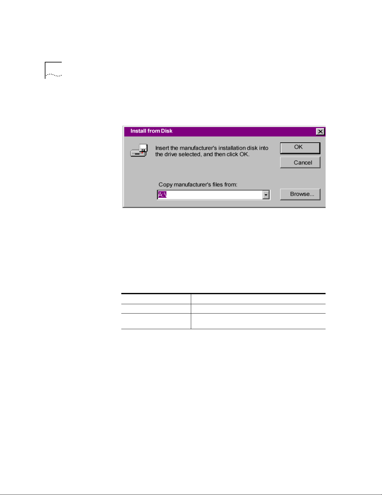
When the following window appears, insert your Connections CD-ROM,
change the default drive in
Copy Manufacturer’s files from:
to
D:\
(or the
correct path of your CD-ROM) and click OK to install the INF file.
Windows 95/98 displays a window asking you to choose your modem
type from the list. Sel ect the your modem from the list and click OK.
Your modem is now ready to use!
Files Needed By Your
modem
Installing the Latest
Software
Accessing Your
Internet Service
Provider
For your modem to work most efficiently, 3Com recommends that you
use the latest version of the modem software and information (INF) file
from the 3Com U.S. Robotics Web site
(http://www.usr.com/home/online/).
This file Does this
The modem software Contains software that contains new feature updates
The INF file Helps your computer work more effectively with your
See Chapter 3,
Upgrading your M odem
modem
for informat io n a bou t up gr adi ng
your Business Modem’s software.
This section explains how to set up you r mode m to acce ss the I nternet or
remote Local Area Networks (LANs) using Windows 95/98 Dial-Up
Networking. To Access Internet Service Providers (ISPs) or remote LANs
you must do the following:
Page 17
Windows 95/98
Step One: Determine if Dial-Up Networking is Installed
1
Click
Start
|
Settings
|
Control Panel
.
1-3
On the Control Pa nel, do uble-click on
2
Network
. The
Network
widow will
appear.
If Dial-Up Adapter Do this
Is listed Go to the section "Installing TCP/IP Sup port" to install Dial-Up
Is not listed Go to Step 3.
Return to the Control Panel and double-click on
3
Programs
Click Windows Setup tab.
4
Double-click on
5
to open the
Networking.
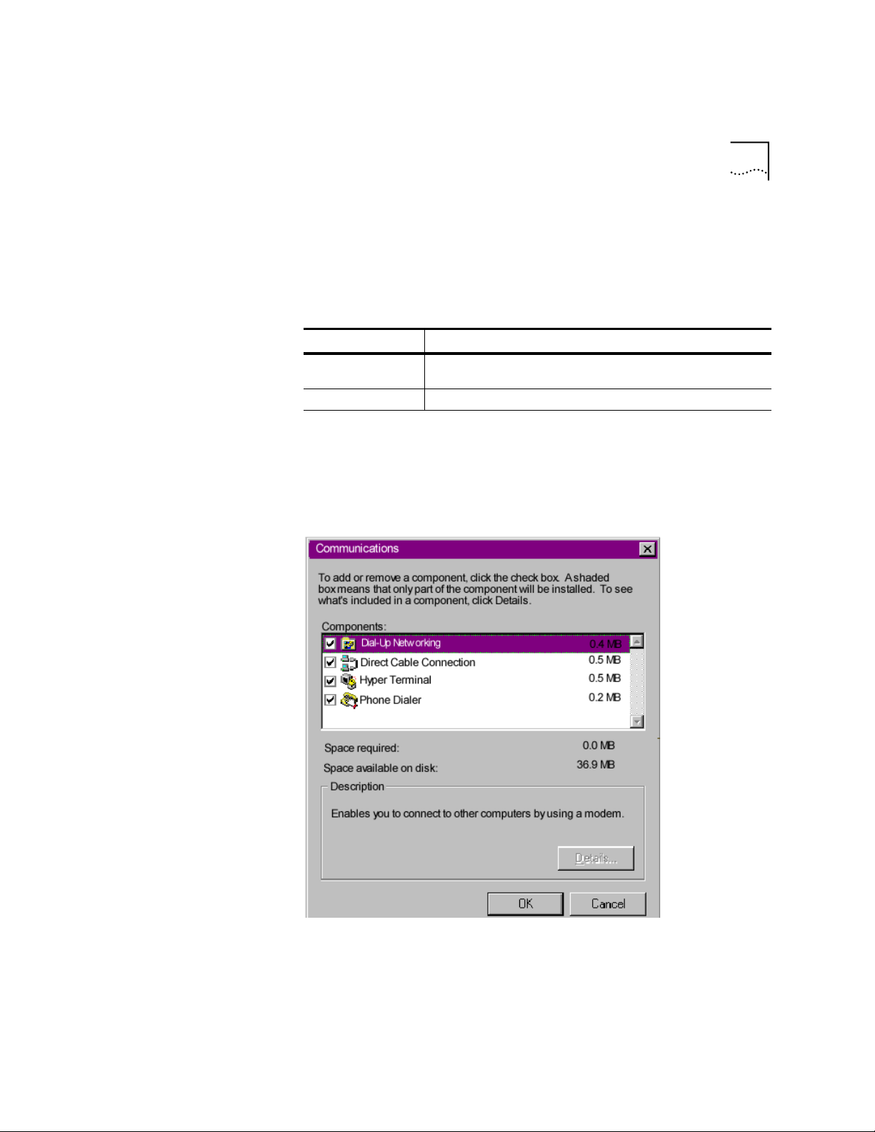
Add/Remove Programs Properties
Communicatio ns.
Add/Remove
window.
The following window appears:
Click on Dial-Up Networking to check the box.
6
Click OK | OK.
7
Page 18

1-4
HAPTER
C
ONNECTING TO YOUR
1: C
8
1
ISP
Insert your Windows 95/98 Setup diskette or CD-ROM when you are
prompted, and Windows 95/98 installs Dial -Up Networking.
Step Two: Installing Dial-Up TCP/IP Support
Click
Start
|
Settings
|
Control Panel
.
On the Control Pane l, double-click on the
2
Network
Determine if the TCP/IP Dial-Up Adapter is installed:
3
IF TCP/IP -> Dial-Up Adapter Do this
Is not listed Click
Is listed Go to Step 3.
window:
Add | Protocol | Microsoft | TCP/IP
Insert your
CD-ROM when you are prompted, and Windows
95/98 installs TCP/IP protocol support.
Network
Windows 95/98 Setup
to display the
diskette or
Step Three: Setting Up a Connection to Your ISP
Click
1
Double-click
2
Select the correct modem, if not already selected.
3
Type a name for the connection and click
4
Type a phone number for the connection and click
5
You should see a message indicating that a new connection was created
6
Start
|
Programs
|
Accessories
Make New Connection
|
Dial-Up Networking
.
.
Next
Next
.
.
successfully.
Click
7
Finish.
| OK.
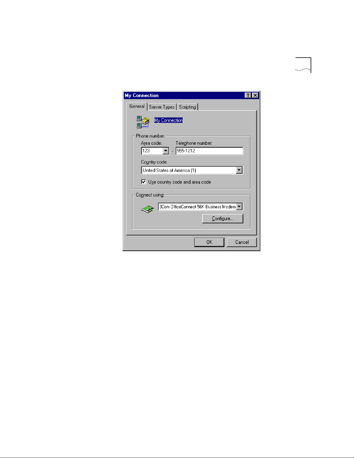
8A New Connecti on
icon will be created in the
Dial-Up Networking
Window. Move your cursor to the new icon yo u have just created and
click the right mouse but ton. Select Pr operti es on the menu to di splay the
following window:
The following screen may vary slightly depending on the version of
Windows 95/98 you are using.
Page 19
Windows 95/98
1-5
9
On the
My Connection
following:
■
Log on to Network
■
NetBEUI
■
IPX/SPX Compatible
window , click
Server Type
, and deselect the
Page 20

1-6
HAPTER
C
ONNECTING TO YOUR
1: C
ISP
Click
10
If your ISP Do this
Gives you a specific IP
or Domain Name
server addresses
Does not give you a
specific IP or Domain
Name server addresses
, and OK.
OK
Step Four: Customizing TCP/IP Settings
Go to
Double-click on the icon you just created to dial your ISP.
Step Four: Customizing the TCP/IP Settings
Depending on the ISP you us e, you may need to customize the TCP/IP
settings. Follow steps 1-6 and if you still cannot connect to your ISP
contact you can contact your ISP for specific information such as an IP
address or Domain Name Servers (DNS).
Double-click
1
My Computer
and double-click
Dial-Up Networking
display all the co n ne c tions you can customize.
Right-click the icon you created and select
2
Connection
On the My Connection properties window, click the
3
properties window.
Properties
to display the
Server Type
to
My
tab.
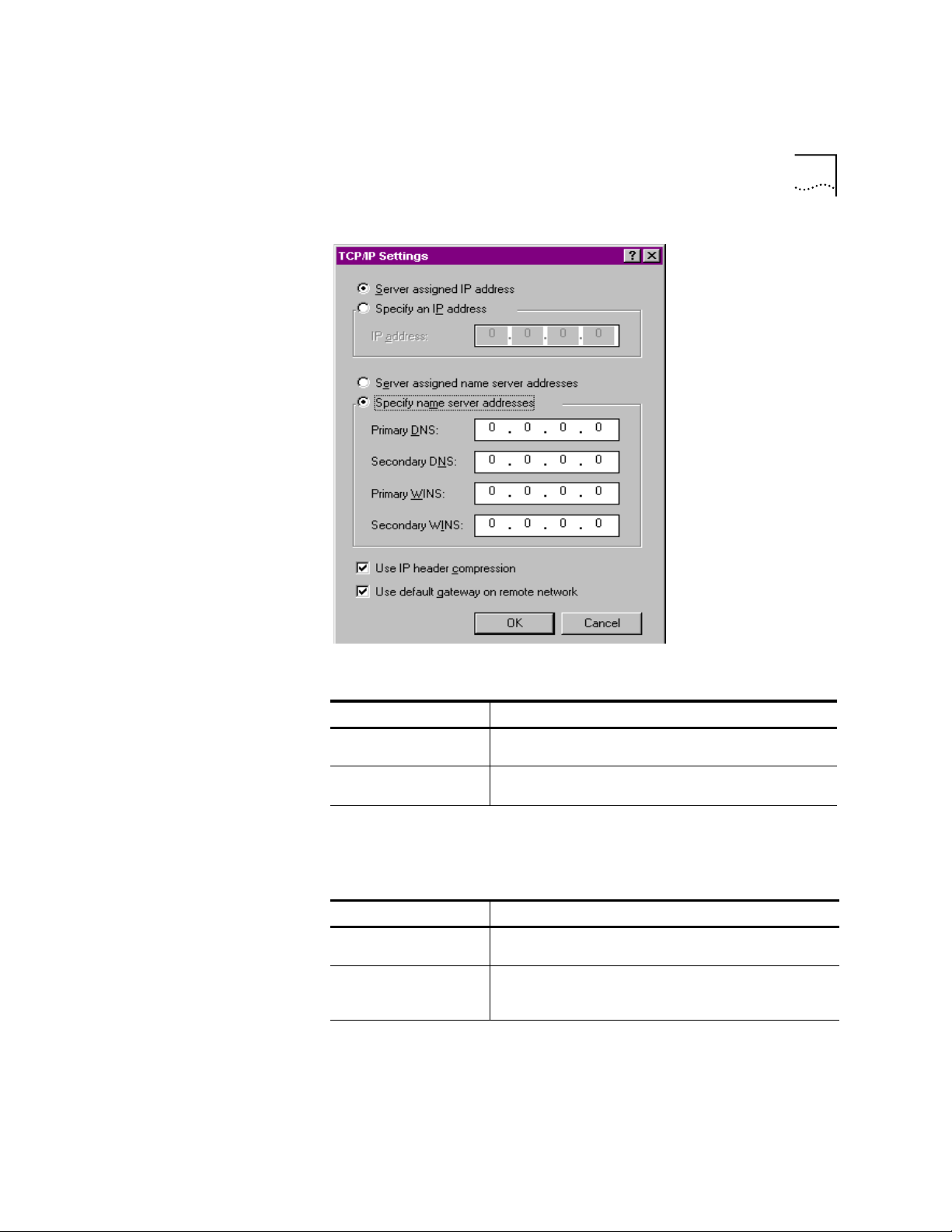
4
Click
TCP/IP Settings
Page 21
Windows 95/98
1-7
Specify an IP address, if needed:
5
If your ISP Do this
Gives you a specific IP
address
Does not give you a
specific IP address
After you specify an IP Address, specify server assigned name server
6
Specify an IP address
Click
provided by your ISP
erver assigned IP address
Click S
and enter the IP address
addresses, if needed:
If your ISP Do this
Gives you specific name
server addresses
Does not give you
specific name server
addresses
Specify name server addresses
Click
server address(es) provided by your ISP
Server assigned server address
Click
and enter the
Page 22

1-8
HAPTER
C
ONNECTING TO YOUR
1: C
ISP
Windows NT 4.0
and Later
Double-click your
7
New Connecti on
icon to connect!
TCP/IP is the main protocol used to transfer data via the Internet. To use
TCP/IP with Windows NT, you must connect to your ISP using a PPP or
SLIP connection.
Each ISP has different requirements. Before using this chapter to
configure Windows NT to acc ess your ISP, contact your ISP to de termine if
they have special instructions for Windows NT users.
For you to Use this connection
Use a dial-up connection to connect over the
Internet.
SLIP only allows you to connect using IP and
does not allow for server assigned IP addresses
or server assign name server addresses.
Use a dial-up connection to connect over the
Internet.
PPP allows you to connect using IPX, TCP/IP,
Netbeui, and other protocols. PPP is a more
recent development than SLIP and has
become the standard way of connecting to
the Internet.
Serial Line Internet Protocol (SLIP)
Point-to-Point Protocol (PPP)
CAUTION:
Before you use these procedures, contact your ISP to
determine if they have any special requirements.
Page 23

Windows NT 4.0 and Later
1-9
What you need
Configuring Your
modem
Before you begin, obtain the following infor ma tion:
■
Does your ISP have a SLIP or PPP account?
■
Your ISP’s telephone number
■
Does your ISP supply a static or dyn amic IP address?
■
Your ISP's primary and secondary DNS servers
■
INF file for Windows NT
Since Windows NT is not Plug and Play compliant, i t is necessary to instal l
the modem in Modem Pr operties.
Your modem should already be installed. If yo u have not connected your
Business Modem to your computer, please refer to the Getting Started
Manual for installation instructions.
Go to
1
Click
2
3
4
5
6
Add
Check
Click
Next
Click
Have Disk
Place the diskette or CD-ROM that was packaged with your Business
Start
|
Settings
|
Control Panel | Modems
Don’t detect my modem; I will select it from a list
.
Modem into your floppy disk or CD-ROM drive. S elect the INF file found
on the disk.
Setting up RAS
Select the COM port for your Business Modem.
7
When the installation is complete, Windows NT will request that you
8
restart your comp uter. Select
Right click on the
1
select
Properties
Click the
2
Select
3
Click
4
Select your Business Modem’s COM port and click OK.
5
Highlight your Business Modem and click
6
Select the function of your modem and click OK.
7
Services
Remote Access Service
.
Add
Network Neighborhood
.
tab.
.
yes
and click
icon on your desktop and
Properties
Configure
.
.
Page 24

1-10
HAPTER
C
ONNECTING TO YOUR
1: C
8
9
ISP
Click
Network.
Select the protocols required to dial in and out with your Business
Modem.
Determining if TCP/IP
is installed
Installing TCP/IP
10
11
Set
Encryption Settings
.
text
Click
Continue
to complete RAS setup.
to
Allow any authentication including clear
TCP/IP must be instal led befor e you c an access the In ternet. Althoug h this
is a standard con fig urat io n, do ubl e-ch eck to m ake su r e T CP/I P is insta lled.
To determine if TCP/IP is installed, perform the following actions:
Select
1
Double-click
2
On the
3
TCP/IP Protocol Adapter
If TCP/IP Protocol is listed, skip to section
4
|
Start
Network
Protocol
Settings | Control Panel
tab, scan down the list of installed protocols to find
.
Configuring a PPP Connection
If TCP/IP Protocol is NOT listed move to the next section.
To install TCP/IP, perform the following actions:
Select
1
Double-click
2
On the
3
|
Start
Network
Protocol
Settings
tab, click
|
Control Panel
, and select the
Add
TCP/IP protocol
list.
.
from the
Configuring a PPP
connection
To configure the Business Modem for a PPP connection, perform the
following actions:
Go to
1
Click
2
Select the
3
Select
4
Deselect
5
If you are connecting to an ISP, uncheck
6
If you are c onnecti ng to an other Windows NT system, Check
Start
New
TCP/IP
NetBEUI
|
Programs
.
Server tab
and
|
Accessories
and select
.
IPX
|
Dial Up Networking
in the Dial-up server type box.
PPP
Enable PPP LCP Extensions
Enable PPP
LCP Extensions
Page 25

Windows NT 4.0 and Later
1-11
Configuring a SLIP
connection
Select
7
8
9
Enable software compression
Specify an IP address by clicking
If your ISP Do this
Gives you a specific IP addre s s Click
Does not give yo u a specific IP address Click
After you specify an IP Address, specify server assigned name server
.
TCP/IP setti n g s
Specify an IP address
the IP address provided by your ISP
Server assigned IP address
.
and enter
addresses, if needed
:
If your ISP Do this
Gives you specific name server
addresses
Does not give you specific name
server addresses
Specify name server addresses
Click
enter the server address(es) provided by your
ISP
Server assigned server addresses
Click
and
The following steps ex plai n ho w to con fig ur e Windows NT fo r us e with a
SLIP connection.
Double-click
1
Click
2
3
4
5
6
New
Select the
Click
TCP/IP settings
Enter the IP address provided by your ISP.
Enter the primary DNS and secondary DNS server IP addresses in the
Dial-Up Networking
Server tab
and select
.
.
in the Dial-up server type box.
SLIP
appropriate nam e server address boxes.
If your ISP requests that you use a specific frame size, select the desired
7
frame size in the Frame Size bo x.
Page 26

1-12
HAPTER
C
ONNECTING TO YOUR
1: C
ISP
Troubleshooting RAS
RAS is significantly easier to troubleshoot th en Win95 Dial-Up
Networking, there are a finite number of problems that one runs into on
a daily basis, and the majority of these are caused by misconfiguration.
Most connection problems can be solved by following these steps:
■
In the
tab, Make sure that the phone book entry settings a re
Basic
correct.
■
Make sure
■
Make sure to that
■
In the phone book settings, under security, it should be set to:
Use Telephony Dialing Properties
Use another port if busy
any authentication including clear text
■
Make sure only the necessary network protocols are selected.
In the
Connect to
window, after you click
■
is unchecked
is not checked.
.
, there should be no
Dial
Accept
domain set. This is on ly for lo gging into NT domain s.
■
Make sure that the TCP/IP settings are correct.
This is a general setup for your Business Modem using Windows NT. If
you are having problems connecting to you ISP, configuring Dial-Up
Networking, or receiving RAS errors, please contact Microsoft Technical
support.
Macintosh
Handshaking Cable
This section explains how to configure your modem for use with
Macintosh computers.
There are many ways to configure your Macintosh to use the Internet.
Consult your Macintosh documentation for more information.
Use a hardware handshaking cable to connect your modem to the
Macintosh.
Page 27

Macintosh
1-13
System Configuration
Accessing the
Internet
Macintosh (230K)
High Speed script
installation
Installing the script
Also, if you aren’t using AppleTalk® Remote Access (ARA), set AppleTalk
to Inactive (in Chooser).
The modem initialization string should be
AT&F1&D0
.
For instructions about how to set up your Macintosh communications
software package, see the software installation instructions that came
with the software.
Accessing the Internet through an ISP requires the following software:
■
MacTCP or Open Transport (TCP/IP from the Control Panels menu),
which has probably already been installed on your Macintosh
■
SLIP or PPP dialing software
You can find public domain PPP dialers (such as MacPPP, FreePPP) on the
Internet.
To enable the 230K DTE support for the Business Modem and 25 mhz
Business Modem you first must install the Macintosh (230K) High Speed
Script and then configure Open Transport PPP.
Download the
1
USRARA.HQX
file.
This file can be found on the internet at
http://www.usr.c om/home/online/ in the software librar y area. It can also
be downloaded from the BBS at 847-262-6000.
After the file is downloaded, it ne e ds to uncom pressed. Wh e n the file is
2
uncompressed the
Inside the USRARA.SE A fo lder i s a r ea dmefi rst.t xt f ile an d the 3C om Hi gh
3
USRARA.SEA
Folder appears.
Speed script.
Move the script file to the following path
4
create a folder named
Modem Scripts
C:\System\Extensions\
.
Once you place the script i n th e Modem Scripts folder you will have the
option to choose the 3Com High Speed in Open T ransport PPP or ARA.
The script will attempt to talk to the modem at 230.4 port speed and if
this fails, it will attempt at the next lowest speed. This will continue until
and
Page 28

1-14
HAPTER
C
ONNECTING TO YOUR
1: C
ISP
the script receives an OK back from the modem an d/or the system
responds with a proper speed.
Configuring Open
Transport PPP
Selecting the correct modem
Go to
1
2
3
Apple Menu | Control Panels | Modem
Modems
In the
to in the
Window, ch oose the
Connect via
drop down box.
Select the correct modem, in the
port
Modem
.
that your modem is connect ed
drop down box.
Page 29
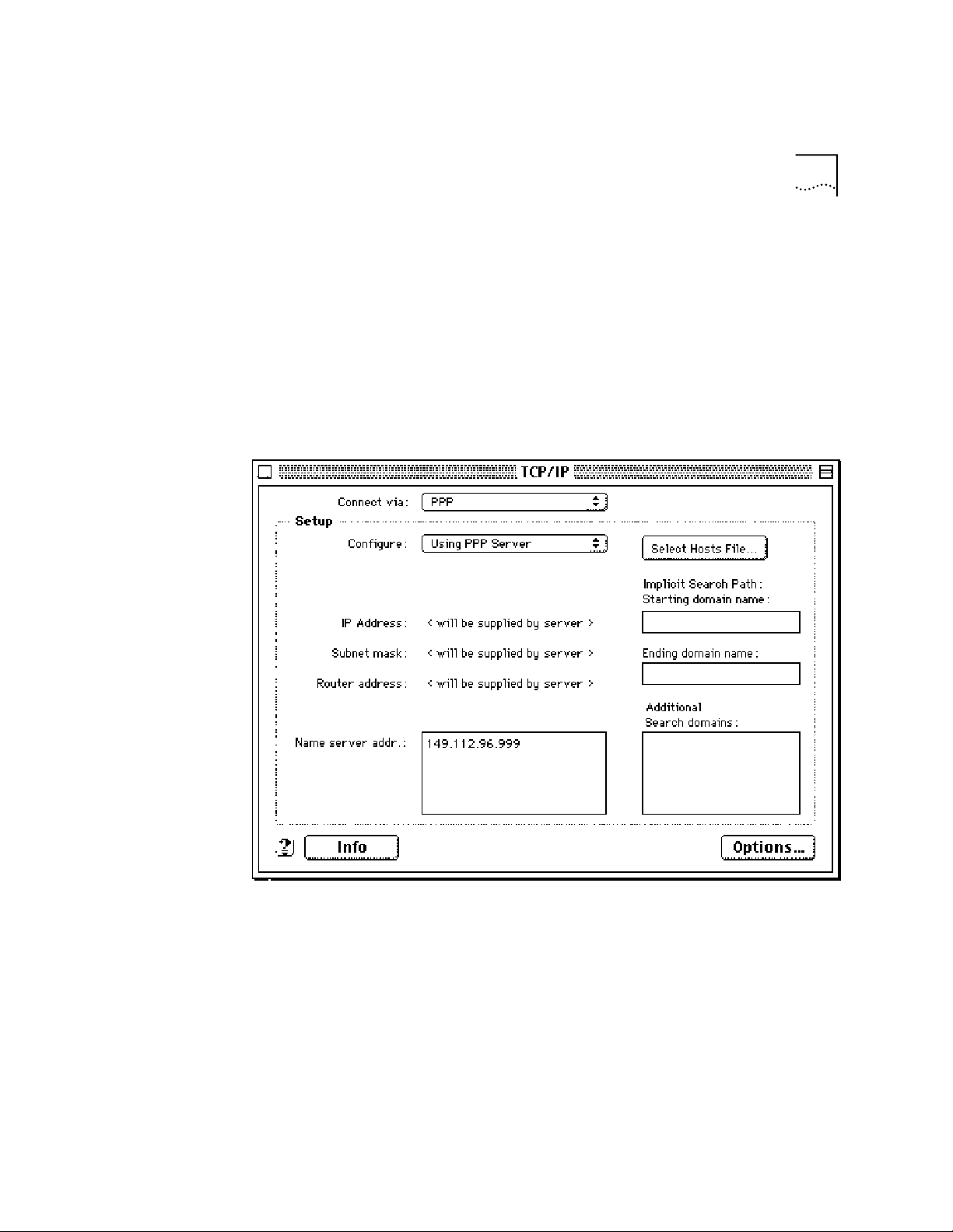
Selecting the correct
TCP/IP settings
Macintosh
1-15
Go to
1
2
3
4
5
Apple Menu | Control Panel | TCP/IP
TCP/IP
In the
Set the
window, select
Configure
in the
PPP
drop down box to
Using PPP Server
Type in your internet service pr ovide rs Domain Name S erver Addr ess(DNS)
numbers in the
Name server addr
box.
Leave the other fields emp ty.
.
Connect via
drop down box.
.
Page 30
1-16
HAPTER
C
1: C
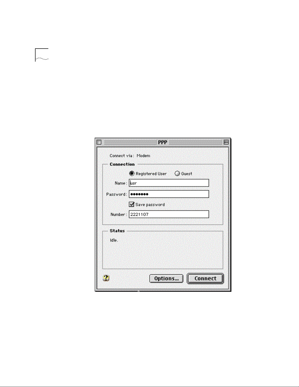
Setting up your ISP
information
ONNECTING TO YOUR
ISP
Go to
1
2
3
Apple Menu | Control Panels | PPP
PPP
In the
window, select
Registered Us er
Type in your Internet Service providers login name and your password in
.
.
the name and password boxes.
Put the phone number that you dial to connect to your internet provider
4
in the number box.
You’ve successfully configured Open Transport PPP!
Page 31

Other Operating Systems
1-17
Other Operat ing
Systems
If You Are Using
Windows 3.x
If You Are Using
MS-DOS
This sections exp la i ns ho w to co n figure your modem for:
■
Windows 3.x
■
MS-DOS
■
UNIX, Linux, or AIX
Windows 3.x comes with a built-in communications software package,
Windows Terminal. You can use Windows Terminal to test your modem
or you can install the communications software package that is included
Connections
on the
CD-ROM.
Because Windows Terminal only supports speeds up to 19200 bps, it is
recommended that you use a third-p arty communications software
package.
Because there is no communications software built in to MS-DOS, you
must install and run a third-party communications software package to
operate your modem.
RapidComm, which is incl uded on the
Connections
CD-ROM, contains
MS-DOS and W i nd ows 3.1 versions of Rap id C o m m .
You must choose the COM port to which your modem is attached in
whatever communications software package you are using.
If You Are Using
UNIX, Linux, or AIX
®
For instructions about how to set up your UNIX
, Linux, or AIX
communications software package, see the software’s installation
procedure.
Page 32

1-18
HAPTER
C
ONNECTING TO YOUR
1: C
ISP
Page 33

2
SING THE
U
This chapter includes information about
■
Basic AT commands
■
Using S-Registers
■
Understanding bit-mapped S-Registers
AT C
OMMAND
S
ET
Overview
General rules for
using AT commands
You can use AT comman ds to change your modem settings at any time.
To send AT commands to your modem, you need to put your
communications software in Terminal Mode. In terminal mode, what you
type is sent direc tly to the modem.
You must follow some general guidelines to send AT commands to your
modem:
■
Type AT before each command and press <ENTER> after each
command.
The exceptions are A/, A> and +++, which require neither
<ENTER>.
■
Leave zeroes off the end of AT commands. A missing numeric
parameter is assumed to be a zero. For example, ATE is equivalent to
ATE0.
■
Create compound commands of up to 56 characters between AT and
<ENTER>. See the following example.
AT nor
Page 34

2-2
HAPTER
C
2: U
SING THE
OMMAND SET
AT C
AT&K3X2DT5551234
AT Attention; a command follows.
&K3 Disable MNP5 data compression; use only V.42 bis compression.
X2 Use the X2 result code subset.
DT Dial the following number using tone dialing.
Hyphens and parentheses add to the count of 56 characters but, spaces
do not.
Basic AT commands
Using S-Registers
The command AT informs the modem that a command is coming. AT
must precede all commands except A/, A> and +++.
To configure your modem to Command
Re-execute the last-issued command.
Repeat the last- issued command until canceled by pressing
any key.
Example:
Sending
Now, if you send
ATD5551234
A/
the modem will dial 555-1234 again.
will make the modem dial 555-1234.
A/
A>
S-Registers are addresses of places in memory where various timing
parameters, redefinitions of selected ASCII characters, and other
configuration settings are stored.
Initially, the S-Register settings for each of the NVRAM templates are the
same. You can overwrite an S-Register’s stored value. See the default
values listed in Appendix A,
S-Registers
, for a complete listing of the
initial settings.
Page 35

Using S-Registers
2-3
Displaying S-Register
settings
Setting an S-Register
You can display S-Registers in a variety of ways. See the table below for
more information.
To display Command
ATSr?
Contents of ONE S-Register
S-Register settings in the NVRAM templates
S-Register settings in RAM (the current configuration)
Example:
Sending
ATS0?
, displays the contents or setting for S-Register
, where r is the
register’s number
ATI5
ATI4
0.
When using the c ommands ATI4 and ATI5, S-Register settings appear a s a
table seven columns wide, each entry of the form, "Smm=nnn" where
mm is a register number between 0 and 70 and nnn is a decimal value
between 0 and 255.
You can configure each S-Register set ting manually.
CAUTION:
If you do not write an S-Register setting with
, the setting
&W
will be retained only until the next reset or power off.
To change Command
Settings for a register in the current configuration
Example
: Sending
ATS0=2
, changes the setting for S-Register 0 to 2. This
ATSr=n
setting will cause th e Bu sine ss Mode m to answer, in Auto Answer Mode,
on the second ring.
In the command ATSr=n, r is the register's number a nd n is a decimal
value from 0-255 (unless otherwise indicated) that specifies the setting.
Page 36

2-4
HAPTER
C
Getting a list of
SING THE
2: U
S-Registers
OMMAND SET
AT C
To display Command
A list of S-Registers
ATS$
In order to issue this command, you must be in Terminal Mode.
See Appendix A, S-Registers for a complete list of S-Registers.
Understanding
bit-mapped
S-Registers
A bit-mapped S-Register uses one number to describe a collection of
settings. Bit-mapping allows us to pack a lot of information in a small
space.
Bit-mapped re gi sters are in the form of Sr.b=n, where r is t h e bit -map ped
register; .b is the bit; n is 0 (off) or 1 (on).
See Appendix A, S-Registers to see how bits are mapped into decimal
values and for information about setting bit-mapped S-Registers.
Page 37

3
Command and
Online Mode s
ODES OF
M
This chapter contains information about
■
Command and Online Modes
■
Controlling Local Echo
■
Data and Fax Modes
If you want to Set the modem to Use this command
Control the modem using AT
commands.
Your modem set to revert to
Command Mode when the
Escape Code (+++) is used.
Your modem to Disconnect
when the Escape Code (+++)
is used.
Return to your connection
after an Online Command
Mode session.
Send the modem commands
while you are on line with
another device.
PERATION
O
Command Mode
Online Mod e
Online Com m and
Mode
+++
(Escape Code)
ATS14.0=0
ATS14.0=1
ATO0
+++
(Escape Code)
DO NOT type
AT
before
+++
or
<ENTER>
after the command
Page 38

3-2
HAPTER
C
ODES OF OPERATION
3: M
Entering Online
Command Mode
Returning to Onli ne
Mode
When the modem is in Online Mode, the only command it recognizes is
an escape code, or +++.
Revert to Command Mode without losing connectio ns by sending
ATS14.0=0
Wait one second after sending the last item of data
5
+++
Type
6
Wait for
7
to the modem before establishing your connection.
OK
to appear before typing any data
You can change the characters used to revert to Command Mode or the
wait time by resetting Register S2 or S12. For more information about
resetting these S-Registers, see Appendix A, S-Registers.
There are tw o ways to return online using the A TOn command.
.
If you want to Command
Return online
Return online and retrain
Example:
Sending
ATO1
, will allow you to resynchronize if you
ATO0
ATO1
experienced errors during a non-ARQ data transfer.
Page 39

Controlling Local Echo
3-3
Controlling Local
Echo
Command-Mode
Local Echo
Online-Mode Local
Echo
There are two local echo settings, one for Command Mode and one for
Online Mode.
You can configure your modem to display the commands you type on
screen by using the ATEn command
.
If you want the commands you type to Command
NOT appear on screen (Command Mode echo OFF)
Appear on your screen (Command Mode echo ON )
ATE0
ATE1
Although you cannot see the command when you set ATE0, the modem
is receiving them .
To configure your modem to di splay a copy of data that is being
transmitted on your screen you can use the ATFn comma nd.
As the modem transmits data to a remote system Command
The modem sends a copy of the data to the screen. Online
local echo ON (“half duplex”).
No copy of the data is displayed on s cree n. Onl ine ec ho OF F
(“full duplex”).
ATF0
ATF1
(default)
ATF0
Example:
Sending
will allow you to see what you are typing in the
display window.
You may see the term duplex used in place of online local echoing,
although the term is not technically accurate.
Page 40

3-4
HAPTER
C
ODES OF OPERATION
3: M
Data and Fax
Modes
Once you are in Command Mode, you can initia lize the modem in Data
or Fax mode.
Fax operatio ns req ui re facsimile-compa tib le communication s so ftw a re
that can send or rece ive Grou p III faxes. Fo llow the instr uctions in yo ur fax
software manual.
The modems default operating mode is Data Mode. Most fax software
automatically switches the device to Fax mode when you run the
program, and resets the device to Data mode when you exit the program
.
If you want the modem prepared to Mode Command
Make calls to and receive calls from other
modems
Make calls to and receive calls from analog
facsimile devices, such as fax modems and
fax machines
Example:
Sending
AT+FCLASS=1
, allows you to receive faxes from fax
Data Mode
Fax Mode
AT+FCLASS=0
AT+FCLASS=1
(Class 1 Fax Mod e)
or
AT+FCLASS=2.0
(Class 2.0 Fax
Mode)
machines.
Class 1 and Class 2.0 Fax Modes refer to standards set by the Electronic
Industries Association/Telecommunications Industry Association. Class 1
Fax Mode is the minimal standard for computer-faxmodem interface.
Class 2.0 Fax Mode refers to the extended computer-faxmodem interface.
Page 41

Data and Fax Modes
3-5
If you are not sure whether your modem is in D ata or Fax mode, use the
AT+FCLASS?
.
command
If the modem
returns a value of
0 Data Mode
1 Class 1 Fax Mode
2.0 Class 2.0 Fax Mode.
This indicates
Whenever the modem is reset using the ATZ command or by turnin g the
power off and then on, it will reset to Data Mode.
Page 42

3-6
HAPTER
C
ODES OF OPERATION
3: M
Page 43

IALING
D
, A
NSWERING, AND
4
Dialing
Dial options
ANGING
H
This chapter explains how to use basic AT commands for:
■
Dialing
■
Carrier loss redial
■
Answering calls
■
Making International calls
■
Call detection
■
Caller ID functions
■
Distinctive Ring support
Y ou can use your modem to dial the spec ified ph one numb er and exe cute
dial options by using the following commands.
U
P
For your modem to Command
phone number
ATD
Dial the specified phone number and execute dial
options (DO NOT use spaces or dashes).
Tone dial.
Pulse dial.
Pause for the length of time specified by S-Register 8.
The default is 2 seconds.
Pause for 125 milliseconds.
Wait for a second dial tone before continuing dialing.
This command only works only if the X3 (or higher)
command has been issued (see Chapter 7,
Result Code Displays
Meanings and Sets
it interprets the W as a two-second pause, unless it
detects a second dial tone within two seconds.
and Appendix D,
). If the modem is set to X2 or lowe r,
Controlling
Result Code
ATDT
ATDP
ATD,
ATD/
ATDW
(Comma)
(Slash)
Page 44

4-2
HAPTER
C
4: D
IALING
NSWERING, AND HANGING UP
, A
For your modem to Command
Wait for an answer (with X3 or higher).
ATD@
Some online services answer the phone and return a
tape-recorded request for information before
processing transactions.
Use the AT@ command to tell the modem to detect at
least one ring, wait for five seconds of silence at the
other end of the call, and then continue.
To use the AT@ command, set the modem to X3, X4 or
X7.
If set X2 or lower, the modem will return an ERROR
message when it encounters the @ character. If set to
X5 or X6, the modem hangs up w he n it de tect s a vo ic e
answer.
ATD;
ATD"
(Semicolon)
Return to Command mode after dialing.
Dial the letters that follow (in an alphabetical phone
number).
If you are including another command after the phone number, use closing
quotation marks before the additional command
IMPORTANT:
With the exception of the above Dial options, your modem will
.
ignore any commands issued after the D in the same command string.
Call a device that can only originate calls. It forces the
ATDR
modem to dial out at the answer frequency or Reverse
frequencies. You can put the R either before or after
the number.
Display different sets of result codes. See Chapter 6,
Controlling Result Code Displays
Result Code Meanings and Sets
and Appendix D,
.
Dial the last-dialed number. Use ATDL instead of using
ATX2D..... X7D
ATDL
A/ if you wish to send the modem non-Dial commands
before dialing again.
Display the last-dialed number.
Dial the number stored in nonvolatile random access
ATDL?
ATDS
n
memory at position n, where n = 0*9. See Chapter 6,
Working with Memory
, for instructions about saving
phone numbers to memory.
Digits 0 through 9, * and # are accepted.
Stop dialing or stop repeating. Type any key
Reissue the last command (Don’t type AT or press
<ENTER>
).
A/
Page 45

Carrier Loss Redial
For your modem to Command
Dial a number, wait 60 seconds for a connection, and
then hang up. Wait two seconds, then redial. Make a
maximum of 10 attempts.
To stop the repeating, press any key during the pause
between dial attempts. If you press any key while the
modem is dialing, that dial attempt is canceled but the
cycle will contin ue
Dial the last-dialed number and repeat it just as the >
command does. Also can be used to repeat any
command.
>
A>
4-3
Carrier Loss Redial
You can set the Business Modem to redial the last-dialed number after it
loses carrier (carrier is the signal maintained between two modems while
they are on line) . This feature is useful for dialed-line connections that
operate unattended.
For your modem to Command
Disable carrier loss redial
Enable carrier loss redial
Wait n seconds between losing the connection and
redialing.
This command also defines the interval (in seconds)
between dialing attempts in the that the first attem pt is
not successful.
Example:
Sending
ATS44=20
sets a 20-second interval between losing
ATS69.1=0
ATS69.1=1
ATS44=
n
the connection and redialing.
Page 46

4-4
HAPTER
C
4: D
IALING
NSWERING, AND HANGING UP
, A
Answering Call s
Force Answer Mode
Auto Answer
Your modem can be configured to answer calls. By de fault, your Busi ness
Modem will not automatically answers calls.
For your modem to Command
Go through the answer sequence when it hasn't
received an incoming call
Or
Manually ans wer a call
ATA
You can set your modem to Auto Answer us ing the ATS0 command
.
For your modem to Command
Receive calls unattended (Auto answer enabled)
Remember to set your communications software to
save incoming messages and/or files.
NOT receive calls unattended (Auto answer disabled)
Example:
Sending
ATS0=0
will not allow your modem to receive calls
ATS0=1
modem to answer on the
first ring)
ATS0=0
(this instructs the
when you are not present.
See the S-Register summar y in Appendix A,
S-Registers
for more
information about instructin g the mo d em to answe r afte r more than 1
ring.
When your modem senses a call coming in, it send s the re sult code RIN G
to your computer, goes off hook, and negotiates for a connection. If
there is no response within 60 seconds, the Business Modem hangs up.
For more information about adjusting the 60-second wait-for-connection
time using S-Register 7, see Appendix A,
S-Registers.
When a call is disconnected, the Business Modem hangs up and returns
the NO CARRIER result code.
If S0=0, Auto Answer is disabled. To determine if Auto Answer is NOT
disabled send the command
and be sure that S0=1-255.
ATI4
Page 47

Making International cal ls
4-5
Hanging up
Making
International calls
Handshaking options
If you want to end a connecti on with a remote device do t he following:
Enter Online Command Mode by t y ping
1
Wait 1 second
2
ATH
Type
3
+++
You can use the ATBn, AT&Gn and ATPn commands for making analo g
international calls above 1200 bps.
The ATBn command controls the handshake options.
.
If you want your modem Command
ATB0
To answer all V.34-type calls, as well as calls fr om overseas,
use ITU-T (formerly CCITT) answer sequence.
NOT to answer V.34-type calls. Use Bell answer tone. This
setting selects HST modulation.
Example:
Sending
ATB1
, will allow your modem to use Bell answer tone
(Default)
ATB1
(selecting HST modulation).
Page 48

4-6
HAPTER
C
4: D
IALING
NSWERING, AND HANGING UP
, A
Guard tone
The AT&Gn command only applies to analog overseas calls at 2400 or
1200 bps.
To set your modem for Command Required in these countries
No guard tone
550-Hz guard tone
1800-Hz guard tone
If you set &G2 you must also send
AT&G0
(Default)
AT&G1
AT&G2
United States and Canada
Some European countries
The U.K. and some Comm onwealth
countries
to the modem. This setting
ATB0
allows the Business Modem to answer all calls from overseas.
Make/Break Ra tio
The A T&Pn command sets the off- hook/on-hook (make/break) interval for
pulse dialin g.
To set you modem for Command
North American make/break ratio (39/61)
United Kingdom make/break ratio (33/67)
AT&P0
AT&P1
Call Detection
Call Detection allows the modem to recognize whether an incomin g call
is analog data or fax.
Call Detection is an optional Service Class 2.0 feature and is also
implemented by 3Com for Fax Class 1 applications.
Page 49

Caller ID Functions
4-7
Caller ID Functions
Service Types
Caller ID is a service provided by local telephone companies. When you
subscribe to caller ID, your phone company begins providing you
real-time information about incoming calls.
The caller ID signal includes the date and time of the call, the phone
number of the calling device, and, optionally, the name of the calling
party. The signal is sent between the first and second rings and must be
decoded and displayed by a device connected to your phone line. The
Business Modem has the ability to decode and display t he caller ID
information.
You can subscribe to Basic or Extended caller ID service. Basic service
offers you the date and time of the call and the calling party’ s telephone
number. Extended service provides the billing name associated with the
calling party’s telephone number in addition to the Basic service
information.
The information the Business Modem actually receives depends on the
service type to which you’ve subscribed, the information that the calling
party’s telephone company provides, and whether the equipment in
between supports caller ID. At mini mum, you wil l always r eceive the date
and time that a call arrived.
If a call arrives without a caller ID signal, the modem will send OUT OF
AREA in place of the pho ne number and name. If the caller ID
information has been bl ocked by the user at the other end, the Business
Modem will send PRIVATE in place of the phone number and name.
Applications of Caller
ID Technology
You can use caller ID to screen calls, keep a record of calls, or prevent
unauthorized access to your network. Third-party database and
telephony applications such as security, call logging, and black-listing
applications exploit the caller ID information provided by the Business
Modem.
Page 50

4-8
HAPTER
C
4: D
IALING
NSWERING, AND HANGING UP
, A
How the Business
Modem Handles
Caller ID
When the modem receives the caller ID signal, it stores the information in
memory. You can access the information at any t ime b y se ndi ng
ATI15
to
the modem.
ati15
3Com OfficeConnect 56K Business Modem CID Status…
80 1E 01 08 31 30 31 35 32 30 33 38 02 0A 37 30
38 35 35 35 30 30 30 31 07 0C 55 2E 53 2E 52 4F
42 4F 54 49 43 53 22
DATE = 1015
TIME = 2038
NMBR = 8475550001
NAME = U.S.ROBOTICS
OK
Using the #CID command (described below), you can have the Business
Modem send the information to your computer between the first and
second RING messages. The call er ID information is displayed only once.
RING
DATE = 1015
TIME = 2038
NMBR = 8475550001
NAME = U.S.ROBOTICS
RING
The information r emains in memory until either you reset the modem or
until it receives ano the r va l id ca lle r ID sig na l .
To be sure that the Business Modem receives the call er ID signal when
auto-answer is enabled, set S0=2 or higher or make sure your
communications softwar e is set to answer on 2 or more rings.
Page 51

Caller ID Functions
4-9
Presentation Formats
The Business Mod e m s e nd s the ca lle r ID in fo rm ati on to your computer
formatted or unformatted. Formatted presentation is a translation of the
caller ID signal into ASCII text. Unformatted presentation is a hexadecimal
representation of the caller ID signal.
An Example of Formatte d caller ID presentation:
RING
DATE = 1015
TIME = 2038
NMBR = 8475550001
NAME = U.S.ROBOTICS
RING
An Example of Unformatted caller ID prese ntati on :
RING
Commands
801E01083130313532303338020A37303835353530303031070C552E532E
524F424F5449435322
RING
The following table describes the AT#CID=n settings.
Caller ID Action Command
Disable Caller ID detection and reporting
Enable Caller ID with formatted output
Enable Caller ID with unformatted output
AT#CID=0
(Default)
AT#CID=1
AT#CID=2
Page 52

4-10
HAPTER
C
4: D
IALING
NSWERING, AND HANGING UP
, A
Caller ID Action Command
Enable Caller ID with formatted outpu t an d na me
suppressed
Enable Caller ID but do not transmit the
information to your computer—retain it in the
Business Modem’s memory
Display the current caller ID setting.
Display the Caller ID settings that are available
AT#CID=3
AT#CID=4
AT#CID?
AT#CID=?
References
Distinctive Ring
Support
For more information about Calling Number Delivery (CND), refer to
Bellcore do cuments TR-TSY-000030 and TR-TSY-000031. To obtain
Bellcore documents, contact:
Bellcore Customer Service
8 Corporate Place
Room 3A184
Piscataway, NJ 08854-4196
(800)521-2673
Distinctive ring is a service provided by local telephone companies that
permits the assignment of multiple phone numbers to one line. Each
phone number is associated with a different ring pattern, and devices
that recognize distinctive ring, like the Business Modem, can be set to
answer only on certain incoming ring patterns.
For example, a fax machi ne, answer ing machi ne, t eleph one , an d modem
could all share t he same line. Each device would have its own phone
number and respon d only to calls intended for that number.
Page 53

Distinctive Ring Support
4-11
There are four ring patterns in common use:
Ring Description
A 1.2 to 2.0 seconds on, 4.0 seconds off.
B 0.8 second on, 0.4 second off, 0.8 second on, 4.0 seconds off.
C 0.4 second on, 0.2 s e co nd off, 0.4 second on, 0.2 second off, 0.8 s e co nd
on, 4.0 seconds off.
D 0.3 second on, 0.2 s e co nd off, 1.0 second on, 0.2 second off, 0.3 s e co nd
on, 4.0 seconds off.
These are graphical depictions of each ring pattern.
Commands
For your modem to Command
Enable recognition of Ring A
Disable recognition of Ring A
Enable recognition of Ring B
Disable recognition of Ring B
Enable recognition of Ring C
Disable recognition of Ring C
Enable recognition of Ring D
Disable recognition of Ring D
Example:
Sending
ATS70.0=1.3=1
ATS70.0=1
ATS70.0=0
ATS70.1=1
ATS70.1=0
ATS70.2=1
ATS70.2=0
ATS70.3=1
ATS70.3=0
to your modem enables the
recognition of ring types A and D only .
Page 54

4-12
HAPTER
C
4: D
Result Codes
IALING
NSWERING, AND HANGING UP
, A
When a call comes in with a ring type A or D, the Business Modem will
send the result co de RING A or RING D, r especti vely. The Business Modem
will ignore other ring types.
If S70 is set to 0 (the default) the Business Modem detects ring types A
and B, sending the result code RING for either ring type. This function is
identical to that of other 3Com modems that do not support distinct ive
ring.
If only one ring type is ena bled, the Business Mo de m wi ll reco gn iz e onl y
the enabled ring ty pe and ignore all others. It will sen d the resul t co de
RING only when it detects the r ing type that's enabled.
If more than one ring type is enabled, the Business Modem will recognize
only the enabled ring types and ignore the others. When a call arrives, the
Business Modem will send its ring type in the result code, for example,
RING C.
Verbal Numeric
RING A 170
RING B 171
RING C 172
RING D 173
Page 55

5
ORKING WITH
W
This chapter contains information about:
■
Saving a phone number to NVR AM
■
Working with Flash Memory
You can upgrade the software held in Flash memory by perfo rming a
software download.
information about performing a software downloads.
See Chapter 3
EMORY
M
, Upgrading your Software,
for more
Overview
Business Modems contain three types of memory that you can interact
with: random access memory (RAM), nonvolati le random access memo ry
(NVRAM), and Flash memory.
Memory type Applies to Loss of power will Command
RAM The current settings. Cancel any changes you
make. To save settings
before resetting the modem,
use &W. See the section
NVRAM Saved settings (any
configurations you
can store, retrieve,
and change).
Flash Three templates of
permanent settings
(the Business
Modem’s operating
software).
Working with RAM
detailed information.
NOT affect your settings.
NOT affect your settings.
You can retrieve the
permanent settings, and
save them to NVRAM, but
you cannot alter them.
for more
ATI4
ATI5
Not
applicable.
Page 56

5-2
HAPTER
C
ORKING WITH MEMORY
5: W
Working with RAM
and NVRAM
Saving a Phone
Number to NVRAM
Example:
Sending
ATI5
will display NVRAM settings on your screen.
To see a complete listing of the permanent settings stored in Flash
memory see
Appendix C
, Flow Control Templates.
You can change any setting just for the current session. For example
AT&N8
setting your Business Modem to
will only allow a connection to a
remote devices at a rat e of 14400 bps un til the modem is re set. Once the
modem is reset, the default variable conne ctio n rate wil l be
re-established.
If you want the new setting to be a de fa u lt, write it t o NVR AM at the
same time. From the example above, you would send
AT&N8&W
to the
modem. The new default setting for your Busi ness Modem will only allow
a 14400 bps connection to a remote device.
To restore NVRAM factory defaults use the AT&Fn command. See
Appendix B,
Alphabetic Comman d Summary
, for more information on
setting &Fn.
For your modem to Command
Write the phone nu mb er (s) to a position (n) in memory. You can
store up to 10 phone numbers of up to 40 characters each in
positions 0-9.
Display the number stored in the last-dialed number buffer
Display the phone nu mber s tor ed in NVRAM a t posit ion n, where
n = 0*9.
AT&Zn=
ATDL?
AT&Zn?
s
CAUTION:
Example:
AT&Z2=555-6789.
ATDS2
Do not include modem commands in
To store the phone number 555-6789 at position 2, type
.
AT&Zn=
s.
If you want to dial the phone number you saved, type
Page 57

Displaying S-Register
Value Information
Working with Flash Memory
5-3
If the call requires a special setting, insert it in the command before the
DSn command. In this e x ample, &M0 (no error control) comes before
DS2. Type:
AT&M0DS2
The AT&Zn=s command functions differently when Dial Security is
enabled. See Chapte r 11,
For your modem to Command
View the contents of a particular S-Register
Dial Security
, for more in formation.
ATSr?
(where r is the number
of the S-Register)
Saving a Command
String to NVRAM
Working with Flash
Memory
Example:
Sending
ATS0?
will allow you to view the contents of Register
S0.
For your modem to Command
Store a command string in NVRAM. The command
string can be up to 30 characters long; spaces do
not count. This command is used so that you can
call another modem without loading your
communications software.
Display the stored command string
AT&ZC=
AT&ZC?
string
The Business Modem permanently stores three configuration
"templates," or prepared sets of commands, in Flash memory. You can
use the &Fn command to load on e of the three configuration templates
from Flash memory into current memory.
To load this configuration template into c u rrent memory Command
No flow control (low performance).
Hardware flow control.
Software flow control.
AT&F0
AT&F1
AT&F2
Example:
Sending
AT&F1
to your modem will load the Hardware Flow
Control Template into RAM Memory.
Page 58

5-4
HAPTER
C
ORKING WITH MEMORY
5: W
Saving ROM
Templates to NVRAM
Default Settings
All of the settings in each template are given in Appendix C,
Flow Control
Templates.
For more information about hardware and software flow control, See
Chapter 12,
Flow Control
.
To save one of the three ROM templates to NVRAM and have it serve as
the reset default, enter
AT&Fn&W
When the Business Modem is turned on it loads the setti ngs stored in
NVRAM. By default, these settings are that same as the &F1 template.
You can save any of the three templates, or save modifi ed versions of
them, in NVRAM for use as power-on defaults.
For your modem to Command Example
Display NVRAM settings (&F1 settings)
Substitute a template (other than &F1)
Save modified versions of the settings to
NVRAM
ATI5 ATI5
AT&F2&W
(Default)
AT
<settings>
AT&F2&W
&W ATS10=40&A2&W
See Appendix C,
default values.
Flow Control Templates
for a complete listing of the
Page 59

ONTROLLING
C
ESULT
R
C
ODE
6
Result Code Display
Commands
ISPLAYS
D
This chapter contains information about:
■
Result Code Display commands
■
Additional Result Code subsets
The commands listed below control whether result codes are displayed,
and in what format they are displayed
.
If you want the modem to Command
Display result codes.
NOT display result codes.
NOT display result codes while in Answer mode. See Chapter
Modes of Operation
4,
Display result codes in numeric form.
Display result codes in verbal form.
Display result code s when originating, answering, and
retaining a ca ll.
Display result code s ONLY when originating a call
Display sets of result codes. See Appendix D,
and Meanings
.
, for a description of modes.
Result Code Sets
ATQ0
ATQ1
ATQ2
ATV0
ATV1
ATS14.1=0
ATS14.1=1
n
ATX
(Default ATX7)
Page 60

6-2
HAPTER
C
ONTROLLING RESULT CODE DISPLAYS
6: C
Additional Resu lt
Code Subsets
ARQ (Automatic Repeat Request) is used in this manual to denote calls
that use error control.
.
For your modem to Command
Display only connection rate.
Display connection rate and ARQ result codes.
Display connection rate, ARQ result code, and protocol
information (V32, VFC, V34, or x2/v.90). If your software
cannot handle the added protocol information, select &A1
or &A0.
Display connection rate, ARQ result code, protocol, error
control (LAPM, MNP, or NONE), and da ta- comp ression type
(V42BIS, MNP5) indicators.
AT&A0
AT&A1
AT&A2
AT&A3
(Default)
The numeric identifiers for &A3 result codes are the same as those used
for &A2. If you r equest numeric display (V0) and &A3, you won’t be able
to distinguish &A2 from &A3 codes.
Page 61

ONTROLLING
C
EIA-232
7
Data Terminal
Ready
IGNALING
S
This chapter contains information about configuring the EIA-2321
signalling between your computer and modem:
■
Data Terminal Ready
■
Data Set Ready
■
Carrier Detect
Your computer sends a Data Terminal Ready (DTR) signal to the Business
Modem when it is ready to send and receive data. The &Dn command
tells the modem how to respond to the DTR signal.
For your modem to Command
Ignore the state of DTR and act as if DT R is always presen t. Use
this command with equipment that cannot provide DTR.
If issued
Command Mode during a call by dropping DTR. Most
communications software packages have a method for
toggling DTR. Refer to your software’s manual for details.
Respond nor mally to the DTR signal.
The Business Modem will not accept commands until your
computer sends a DTR signal. The call will end when the DTR
signal is dropped.To change the DTR recogn ition time, set
S-Register 25. See Appendix A,
information.
Business Modem hangs up and resets upon loss of DTR signal.
before connecting with another device
S-Registers
for more
, enter online
AT&D0
AT&D1
AT&D2
AT&D3
Example:
dropping DTR will enter Command Mode.
Sending
1.The EIA-232 Standard was formerly known as RS-232 (RS stands for
Recommended Standard).
AT&D1
before connecting with another device,
Page 62

7-2
HAPTER
C
7: C
ONTROLLING
EIA-232 S
IGNALING
Data Set Ready
Under normal conditions, the Business Modem sends a Data Set Ready
(DSR) signal to your computer when it is ready to send and receive data.
CAUTION:
Do not change the default se tting of &S0 unless you know
that your installat ion requires a different setting. Few Windows
communications programs, if any, will require the Business Modem to
control DSR (&S1).
Use the following command to control how the modem sends the DSR
signal.
For you modem Command
To send the DSR signal at all times.
When originating a call, to send the DSR signal after dialing
when the Business M ode m de tect s th e re m ote analog device’s
answer tone
When answering a call, to send DSR after the Business Mod em
sends its answer tone.
After sending Carrier Detect (CD), to send a pulsed DSR signal,
followed by a Clear to Send (CTS) signal. Use this option for
specialized equipment such as automatic call back units.
After sending Carrier Detect (CD), to send a pulsed DSR signal.
To send a DSR signal to your computer at the same time the
Business Modem sends the CD signal.
To send DSR normally (with CTS) after sending CD.
In order to change the DSR pulse time (in 20-second
increments), set S-Register 24. (See Appendix B,
Command Summary
).
Alphabetic
AT&S0
AT&S1
AT&S1
AT&S2
AT&S3
AT&S4
AT&S5
(Default)
Example:
Issuing
AT&S3
configures the Business Modem to send a
pulsed DSR signal after sending the Carrier Detect (CD) signal.
Page 63

Carrier Detect
7-3
Carrier Detect
Carrier means there is communication with the device on the other end
of the connection. Under normal conditions, the Business Modem sends
a Carrier Detect (CD) signal in response to establishing a connection with
another modem. You can use the AT&Cn command to control how the
Business Modem sends the CD signal.
.
For your modem to Command
Have CD always ON.
Send CD normally (the Business Modem sends a CD signal
when it connects with anothe r device, and drops the CD sign al
when it disconnects).
AT&C0
AT&C1
Page 64

7-4
HAPTER
C
7: C
ONTROLLING
EIA-232 S
IGNALING
Page 65

8
ONTROLLING
C
This chapter contains information about
■
Serial port rates
■
Connection rates
■
Controlling Link Speeds with &N and &U
■
Setting DTE Rate to 230 Kbps
D
ATA
R
ATES
Overview
Serial Port Rates
You can set the Business Modem to use fixed or variable serial port rates
and fixed or variable connection rates. Serial port rates pertain to data
transferred between your computer and the Business Modem.
Connection rates pertain to data transferred between the Business
Modem and the device at the other end of a connection.
You set a fixed serial port ra te to get the hi ghest p ossible thr ough put and
the best performance . Set a variab le rate to all ow the Busi ness Mod em to
match the connection rate.
Your software must support fixed or variabl e serial po rt rates.
Page 66

8-2
HAPTER
C
ONTROLLING DATA RATES
8: C
Your software may use terms such as locked serial port (fixed rate) or
autobaud (variable rate).
To allow your modem
To change its serial port rate to match the
connection rate.
To always communicate with an attached
device at the rate at which you have set
the terminal or software, regardless of
the connection rate.
For the greatest throughput, set the serial
port to 115200, 57600, or 3 8400 bp s for
high-speed calls, a nd to at l east 9600 bps
for 2400-bps calls.
To shift its serial port rate to a rate that
you specify using your communications
software (for example, 38.4 Kbps) when
the Business Modem connects in ARQ
mode.
If the connection is not under error
control, the Business Modem behaves as
if it was set to &B0 and switches its serial
port rates to match the connection rate
of each call.
To implement this feature, first set your
software to the desired rate. Then send
AT&B2&W
The Business Modem stores the rate of
the command in NVRAM along with the
current settings. The Business Modem
checks NVRAM for the specified serial
port rate each time it makes an ARQ
connection.
When saving s ubsequent configurations
to NVRAM, be sure your software is set to
your selected serial port rate so the
correct rate is maintained.
to the modem.
Set the serial port
rate as
Variable
Fixed
Fixed for ARQ calls
and
Variable for non-ARQ calls when
answering only.
See Chapter 13,
Compression, and Error Control, for
more information about ARQ
Command
AT&B0
AT&B1
(Default)
AT&B2
Handshaking, Data
The serial port rate MUST be equal to or higher than the Connection rate
(&Nn).
Page 67

Connection Rates
8-3
Connection Rates
Y ou can set the Business Modem to a fixed or variable connection rate for
data calls. Set a variable rate to have the Business Modem negotiate with
the remote device for the highest possible connection rate. Set a fixed
rate to connect only at a specified rate. Yo u might use a fixed rate to filter
calls for security or other reasons.
To allow your modem to Set connection rate as Command
Negotiate for the highest po ssible rate. Variable
Connect only if the remote device is
operating at the rate you specify. See
below.
To connect at this
rate
300 bps
1200 bps
2400 bps
4800 bps
7200 bps
9600 bps
12.0 Kbps
14.4 Kbps
Command
AT&N1
AT&N2
AT&N3
AT&N4
AT&N5
AT&N6
AT&N7
AT&N8
Fixed
To connect at this
rate
16.8 Kbps
19.2 Kbps
21.6 Kbps
24.0 Kbps
26.4 Kbps
28.8 Kbps
31.2 Kbps
33.6 Kbps
AT&N0
AT&N1-AT&N16
Command
AT&N9
AT&N10
AT&N11
AT&N12
AT&N13
AT&N14
AT&N15
AT&N16
AT&N8
Example:
Sending
will only allow connections with r emote devices
that are oper ating at 14.4 Kbps.
Page 68

8-4
HAPTER
C
ONTROLLING DATA RATES
8: C
Controlling Link
Speeds with &N
and &U
Controlling Link
Speeds
Limiting the Highest
Possible Connect
Speed
You can use the &N and &U commands to control link speeds.
Use the following table to determine how to use &N and &U commands:
To limit the Use
Highest possible connect speed
Lowest possible connect speed
Range of possible connect speeds
AT&N
AT&U
AT&N
and
AT&U
The default values for &N and &U are 0. If you change these val ues, you
will limit the speeds at which you can connect. 3Com recomm ends that
you do not alter these values.
The &N command, when used in conjunction with the &U command,
allows you to limit the highest possible connect speed. If a remote
modem attempts to connect to your Business Modem at a speed higher
than &N, your Business Modem will not allow it to connect .
To limit the Use this command Where x i s
Highest possible connect
speed
AT&N=x
A value from 0 to 32
For a complete list of conne ct spe eds, se e the table in se ction
Command Values
.
&N and &U
Page 69

Controlling Link Speeds with &N a n d &U
8-5
Limiting the Lowest
Possible Connect
Speed
Limiting a Range of
Possible Connect
Speeds
The &U command allows you to li mit the lowest possible connect speed.
If a remote modem attempts to connect to your Business Modem at a
speed lower than &U, your Business Modem will not allow it to connect.
To limit the Use this command Where x i s
Lowest possible connec t
speed
See the table in the sectio n
AT&U=x
A value from 0 to 32
&N and &U Command Values
for connect
speed values.
By setting &N and &U values, you can limit the range of speeds at which
your Business Modem connects. If a remote modem does not connect to
your Business Modem at a range betw een the speeds designated by the
&N and &U commands, your Business Modem will not allow it to
connect.
The link speed associated wit h t he &U argument CANNOT be grea ter
than the link speed associated with &N argument.
Use the following table to understand the relationship between &U and
&N commands:
If &U And &N Then your modem
Equals zero Equals zero Connects at the highest possible
speed.
Equals zero Is greater than zero Connects at the &N speed only.
Is greater than zero Is greater than zero and
greater than &U
Connects at the highest possible
speed in the range from &U to &N.
Page 70

8-6
HAPTER
C
ONTROLLING DATA RATES
8: C
&N and &U Command
Values
Use the following tabl e for a complete list of &N and &U link speeds and
their associated indexes:
Link Speed Index
Highest 0
300 1
1200 2
2400 3
4800 4
7200 5
9600 6
12000 7
14400 8
16800 9
19200 10
21600 11
24000 12
26400 13
28800 14
31200 15
33600 16
28000 17
29333 18
30666 19
32000 20
33333 21
34666 22
36000 23
37333 24
38666 25
40000 26
41333 27
42666 28
44000 29
45333 30
Page 71

Link Speed Index
46666 31
48000 32
49333 33
50666 34
52000 35
53333 36
54666 37
56000 38
57333 39
Setting DTE Rate to 230 Kbps
8-7
Setting DTE Rate to
230 Kbps
The DTE rate of your Bu sin ess Mo dem has be en i nc r ease d to 2 30 kbp s t o
enhance throughput.
This command is only support ed on Business Modems attached to high
speed serial cards.
Page 72

8-8
HAPTER
C
ONTROLLING DATA RATES
8: C
Page 73

CCESSING AND
A
ONFIGURING
C
9
Overview
THE
This chapter contains information about:
■
Setting up remote access
■
Accessing the host
■
Quitting a remote access session
You can set up the Business Modem so other devices can view or change
its configuratio n remo tel y.
You should be familiar with these terms before you continue:
Local The device that is directly con nected to the computer
Remote The device at the ot her end of a telephone connection.
Host The Business Modem that will be accessed and
Guest The device that will access and control the host
USINESS
B
ODEM
M
you are using.
controlled by other devices.
Business Modem.
EMOTELY
R
Setting Up Remote
Access
At the Host Business
Modem
Prepare to sen d AT commands by putting your communications sof twar e
1
in Terminal Mode.
Page 74

9-2
HAPTER
C
CCESSING AND CONFIGURING THE BUSINESS MODEM REMOTELY
9: A
Enable remote access.
2
Set Register S41 f or a val ue of 1 or g r e ater. S41 sets t he numb er of l og- in
attempts available to the remote user. A setting of zero allows no log-in
attempts disabling remote access.
Example:
Sending
ATS41=1&W
allows for 1 log-in attempt by a remote
user.
Set one or two remote-access passwords.
3
You can set tw o pa ss w o rds to al lo w different leve ls of ac ce s s to eac h
Business Modem
Use this command to assign a
To allow guest users to
View
the Business Modem’s configuration.
View
configuration.
Example:
the password
and
change
the Business Modem’s
Sending
AT%P1= corn
corn
. The user can view and change the Business Modem’s
will allow a remote user to log-in with
remote-access password
AT%P0=
AT%P1=
password
password
configuration.
Remote-access passwords can be up to eight alphanumeric characters
long, and are not case-sensitive
Page 75

Accessing the Host
9-3
Other Remote-Access
Commands
Accessing the Host
At the Guest Device
The table below is a list of remote-access configuration commands.
For your modem to Command
Display a view-only password
Display a view-and-change password
Erase a view-only password
Erase a view-and- c h ang e pas s w ord
Disable remote access entirely
Example:
Sending
WARNING:
access (using
AT%P1=
If you erase the%P1 password without disabling remote
ATS41=0
will erase the view and change password.
), anyone could access the Busi ness Modem and
AT%P0?
AT%P1?
AT%P0=
AT%P1=
ATS41=0
change its configuration.
The guest device requires no configuration to access the host. Follow
these steps:
Be sure that the host device has enabled remote access and is set to
1
auto-answer (
Call the host device (although it doesn’t matter which device originates
2
ATS0=1
). Know the password, if yo u will ne e d on e .
the call).
After a connection is established, do this:
3
Pause 4 seconds.
a
Type 4 tildes: ~~~~
b
Pause 4 seconds.
c
The administrator of the host device can change the remote-access
character using S-Register 42, and the pause duration using S-Register
43. See Appendix A,
S-Registers
for more information.
Page 76

9-4
HAPTER
C
CCESSING AND CONFIGURING THE BUSINESS MODEM REMOTELY
9: A
You should see a display similar to this:
4
3Com OfficeConnect 56K Business Modem Remote Access Session
Serial Number 000000A000000001
Password (Ctrl-C to cancel)?
There is a 3-minute time limit for ent ering the password. If the number of
unsuccessful log-in attempts exceeds the set limit, the host device returns
online and refuses any further log-in attempts during the remainder of
the connection.
When the host accepts the p asswor d, the followi ng messag e and p ro mpt
will appear on your screen:
Remote Access granted
Remote->
You may not be prompted for a password. If you aren’t, password
security is not active. The following prompt appears on your screen after
you type the four tildes:
Viewing and
Changing the Host’s
Configuration
Remote Access granted (query only)
Remote->
During a remote-access session, the maximum number of character s
between carriage returns is 40.
Once you've gained guest access to a host, you can communicate with
the host just as if you were entering commands from its attached
computer.
Page 77

Accessing the Host
Depending on your access privileges, you can use the regular set of
Business Modem AT commands.
If you have this access privilege You can use
View-only Any of the inquiry (ATI) commands
View and Configure Any of the Business Modem commands,
except those that cannot be used while
online (for example, ATD or ATA). You can
also use remote configuration commands.
See the next section for examples.
9-5
Remote
Configuration
Commands
CAUTION:
Be careful not to send
ATZ or ATZ!
or you will lose the
connection!
There are special commands that can be used only during a
remote-access session.
You can change the host Business Modem’s serial port rate by using the
AT%Bn command.
To change the host
Business Modem’s
serial port rate to
110 bps
300 bps
600 bps
1200 bps
2400 bps
4800 bps
Example:
Sending
Command
AT%B0
AT%B1
AT%B2
AT%B3
AT%B4
AT%B5
AT%B6
will change the Business Modem’s serial port
To change the host
Business Modem’s
serial port rate to
9600 bps
19200 bps
38400 bps
57600 bps
115200 bps
Command
AT%B6
AT%B7
AT%B8
AT%B9
AT%B10
rate to 9600 bps.
Page 78

9-6
HAPTER
C
CCESSING AND CONFIGURING THE BUSINESS MODEM REMOTELY
9: A
You can use the AT %Fn command to control the data format .
To change the data format to Command
No Parity (8 data bits)
Mark parity (7 data bits)
Odd Parity (7 data bits)
Even parity (7 data bits)
Y ou can use the A T%Cn command to control whether and when to apply
changes to the conf iguration
For your modem to Command
Defer configuration changes to when the call
ends.
Restore the origin al configuration.
Use this comman d to cancel any changes made
during remote access and restore the original
configurat ion.
Force configuration changes.
Use this command to make configuration changes
take effect immediately. We do not recommend
forcing changes unless it is absolutely necessary
because an un reliable connection, or even a loss
of connection, may result.
AT%C0
AT%C1
AT%C2
AT%F0
AT%F1
AT%F2
AT%F3
(Default)
Example:
Sending
AT%C1
will cancel any changes made to the modem
during a remote access session and restore it to the original
configuration.
Even though, by defaul t (%C 0), the cha nges you make do n ot take effect
until the next connecti on, the ne w confi gur ati on is r efle ct ed immed iate ly
in inquiry responses (ATIn).
Commands that have been written to NVRAM (using &W) and forced
configuratio n cha n ge s (%C2) will not be restore d to th ei r pre v io us
settings when you send the host AT %C1.
After you make changes to the host’s configuration, the remote- access
prompt changes from
Remote->
Remote+>
to
.
Page 79

Quitting a Remote-Access Session
9-7
If you restore the original configuration using the AT%C1 command, the
first prompt is restored, assuring you the original configuration is intact.
Quitting a
Remote-Access
Session
If you want to quit the remote-access login
before
you have entered the
password, return online by pressing <Ctrl>C or typing ATO.
After
you’ve entere d the passwo r d, you can quit by sen ding on e of t hese
commands:
To end the remote-access session Command
And keep the connection.
And end the connection.
End the connection, and reset the host modem.
ATO
ATH
ATZ
Before you disconnect, issue the ATI 5 command to the remote modem
and check its S41 setting . Make sure S 41 is set for a value o f 1 or great er.
If S41 is set to 0, when you disconnect you will not be able to access the
remote modem again. To prevent this send ATS41=1&W before you
disconnect.
Page 80

9-8
HAPTER
C
CCESSING AND CONFIGURING THE BUSINESS MODEM REMOTELY
9: A
Page 81

10
IAL
D
This chapter contains information about:
■
Setting up Dial Security
■
Maintaining s ecurity accounts
■
What the guest user needs to do
■
Configuring dial security remotely
ECURITY
S
Overview
Dial Security is designed to protect networks and data centers from
unauthorized access.
You should be familiar with these terms before you continue:
Local The device that is directly con nected to the computer
Remote The device at the ot her end of a telephone connection.
Host The Business Modem that will be accessed and
Guest The device that will access and control the host
You can configure up to 10 acc oun ts: o ne a dmi nistr ati ve a ccount for you
and nine accounts for guest users. The account pr ofiles are stored in the
host Business Modem’s nonvolatile random access memory (NVRAM).
There are two forms of Dial Security; each will be explained later in this
chapter:
■
Autopass
■
Password Prompting
you are using.
controlled by other devices.
Business Modem.
Page 82

10-2
HAPTER
C
10: D
IAL SECURITY
Setting up Dial
Security
Here is a summary of the steps for setting up Dial Security:
■
Set up an account for yourself.
■
Identify your account as the Administrative Accou nt.
■
Set up guest-user accounts.
■
Enable local (host) security.
■
Choose a Dial Security method.
■
Enable Dial Security.
■
Activate the Dial Security settings.
Set up an account for yourself.
1
Use any of the 40 available accounts (numbered 0-39) for your account.
Use the AT%An command to set up user accounts. See the figure below
for the five fields to concern yourself with.
The AT%An command is automatically written to NVRAM. It does not
require you to send &W.
WARNING:
Do not insert spaces between commas or between fields
and commas. Spaces will invalidate the command.
Page 83

Setting up Dial Security
10-3
Dialback options
You can set the Business Modem to automatically di alback a certain
number after a client modem dials in.
Count your commas! There should always be four commas in the %A
command.Do not insert spaces between commas or between fields and
commas. Spaces will invalidate the command.
To make the host Business
Modem
Hang up and then dial bac k a
guest device at a specified
number.
Expect a pause o f
approximately 1.5 minutes
before the modem dials back.
You cannot alter t he duratio n
of the pause.
Prompt you to enter a
number at which to dialback
a device, and then have the
Business Modem dia lback the
device at that number
Disable dialback
Command Example
AT%A0=
,y,n,1
and phone number
AT%A0=
,y,y,
AT%A0=
,n,,
password
area code
password
password
,y
AT%A0=corn,y,y,n,1,8
475555555
,y
AT%A0=corn,y,y,y,
,y
AT%A0=corn,y,n,,
To enable Dialback, you must enable Dial Security with Prompting. See
step 6.
Identify your account as the Administrative Accou nt
2
For your modem to Command Example
Identify your account as the
Administrative Account
AT%L AT%L=PW0
This example sets account 0 as the
Administrative Account.
Once you set the administrati ve password , you cannot view o r modify the
guest account profiles unless you enter the correct administrative
password.
WARNING:
Be sure to remember your administrative password. If you
enable Dial Security and then forget your administ rative password, you
Page 84

10-4
HAPTER
C
10: D
IAL SECURITY
will be locked o ut of th e Business Modem’s dial security features. You will
need to restore the factory defaults. Thi s will erase ALL passwords and
you will have to reconfigure all your accounts.
Set up guest-user accounts.
3
Use the AT%An command to set up guest-user accounts in th e same way
you set up your administrative account. You can set up nine guest
accounts. Refer to the figure in step 1 regar ding information about
formatting the AT%An command.
After you have enabled the guest accounts, make sure the guest users
know their passwo rds and the lo g-in procedure.
Modifying Accounts
After you have set up an account, you can modify each field
independently. If a field is to remain unchanged from its original setting,
just insert a comma, as shown:
AT%A1=,,,Y,
The command above allows the guest user to supply a dialback number
that is different from the one stored in the original account record.
Enable Local Security.
4
WARNING:
If you do not enable Local Security, the Dial Security settings
will not be protected and other users will be able to change or erase
them.
For your modem to Command
Protect the administrative password (local security
enabled)
ATS53.2=1
You must use the &W command to save the settings in NVRAM. If you
don’t, the next time you reset or power off the Business Modem, Dial
Security will be disabled.
Decide which Dial Security option to use.
5
You can choose from the two types of Dial Security: Auto pass an d
Password Prompting.
Page 85

Setting up Dial Security
10-5
Autopass Prompting
Password Prompting
Autopass is the default form of password protection. Autopass
automates the process of logging in to the host modem, but it requires
the guest and host devices to be Business Modems.
When a guest device attempts an Autopass connection, the gue st
includes its passw o rd in its V. 4 2 error-control request. The host modem
checks all the enabled passwords in its security accounts for a match.
Password Prom pting allo ws connections wit h
any
guest device, as long as
the guest user knows the correc t password.
When the host has Password Promp ting enabled , it asks guest users for a
password. The host modem check s the recei ved password aga inst each of
its active Security accounts.
The table below is a comparis on between Autopass and Password
prompting.
When using Autopass Prompting When using Password Prompting
Both the host and guest devices are made
by 3Com and have Dial Security enabled.
The connection between the Business
Modems or modems is under V.42 error
control (See Appendix B, Alphabetic
Command Summary for information
about using
If the guest includes an invalid password,
the host sends an INVALID PASSWORD
message and hangs up.
If the guest includes a valid password, the
host permits a secure connection.
If the guest did not enable Dial Security,
the host will not accept the call unless
prompting is enabled on the host
Business Modem.
AT&M4
or
AT&M5
)
Guest devices don’t have to support
3Com Dial Security.
V.42 error-control connections aren’t
required
If the guest sends an invalid password,
the host prompts twice more before
disconnecting.
If the guest does not send a password
after 60 seconds, the host disconnects.
The host will still always respond to a
correct Autopass attempt.
Page 86

10-6
HAPTER
C
10: D
IAL SECURITY
Enable Dial Security.
6
WARNING:
Before you enable Dial Security, you must set up an
administrative account and password. See Steps 1 & 2.
For your modem to enable Command
Autopass Dial Security
Dial Security with Password Prompting
(this also enables Autopass)
Dialback Secur i t y, enab le Password
Prompting and enable Dialback in each
guest account
Example:
Issuing
AT%A3=corn,y,y,y,5551234
ATS53.0=1
ATS53.0=1.1=1
AT%An=
number
where n is the account number
See the figure in p revious section,
Setting Up Dial Security
information.
password
,y,y,y,
phone
for more
to your modem will
enable Password Prompting and Dialback for account 3, which has the
password
corn
.
You must use the &W command to save the settings for Enabling
Autopass Dial Security and Dial Security with Password Prompting. If you
don’t, the next time you reset or power off the Business Modem, Dial
Security will be disabled.
If you need a reference when setting these command, you can use the
ATI10 command. See Appendix B, Alphabetic Command Summary for
more information about the ATI10 command.
7
Send
ATZ
or
ATZ!
to activate the Dial Security settings!
Page 87

Maintaining Security Accounts
10-7
Maintaining
Security Accounts
Once the administrative password is set and Dial Security is enabled, the
administrator is the only one who can access account information.
You can use the AT%S = and AT%E= commands to change and modify
account information.
For your modem to Command
administrative password
Access accounts by disabling local secu rity
View account information, once access has been
granted. Re mote users may only use this
command during remote-access sessions if
local-access security is disabled .
Erase local-access password
Erase Autopass password
Erase passwords in accounts 0-9
Erase phone numbers in accounts 0-9
Disable Account, Dialback, and New Number
fields in accounts 0-9.
Edit or overwrite an individual account or an
individual accoun t field
Reset &F settings and disbale passwo rd
protection
AT%S=
ATI10
AT%E=1
AT%E=2
AT%E=3
AT%E=4
AT%E=5
AT%An=
where n is the account number
(see the figure in previous
section,
Security
Press the RESET button on the
back of the modem when
offline (same as
Setting Up Dial
for more information)
AT&FS53=0
)
Remote
Configuration
Example:
Sending
AT%E=3
erases passwords for accounts 0- 9.
When using the AT%S= command, the device echoes the administrative
password, which is case-sensitive. Business Modems will accept an inv alid
password entry, but will lock out users from the security commands.
For example, if the passwor d is Green, but you enter GREEN, an OK is
displayed. However, if you try to type a security command (for example,
ATI10 to view accounts), an [ACCESS DENIED] message is displayed.
Dial Security accounts may be configured remotely. (See
Security Remotely
at the end of this chapter.)
Configuring Dial
Page 88

10-8
HAPTER
C
10: D
IAL SECURITY
What the Guest
User Needs to Do
When guest users want to ca ll in to the host (assumi ng you have en abled
Dial Security by entering
■
They must know the password.
■
If you have enabled Dialback, they must set their device to
ATS53.0=1
),
auto-answer.
If the host has security enabled, get a password from the host’s
1
administrator. The password is case-sensitive, so be sure to copy it
correctly.
If the host ha s pro mpting en abled an d the ho st operato r enables Dialback
for your account, skip to Step 3.
For guest users with Business Modems:
2
Create a security account using the password the host’s administrator
a
asked you to use. (See
Setting Up Dial Security
, earlier in this cha pt er,
for instructions.)
You need to assign the password as your Autopass password.
b
For your modem to Command
Assign the password as your
Autopass password
AT%V=PW
the account you set up.
n
, where n is the number of
Example:
Sending
AT%V=PW3
will assign the password as an Autopass
password for accoun t 3.
Check to see that you set your Autopass password correctly by using
c
the ATI10 command.
Your Autopass password appears beside AUTOPASS PASSWORD, if
you have done al l t he ste p s co rrectl y.
Once the Autopass password is set, enable your Business Modem’s
d
Dial Security.
For your modem to Command
Enable Dial Security
CAUTION:
If you do not follow an S-Register setting with &W, the
ATS53.0=1
setting will be retained only until the next reset or power off.
Page 89

Configuring Dial Security Remotely
If Dialback is enabled at the host Business Mo dem’s site, set your modem
3
to answer the host Business Modem when it dials back.
For your modem to be set Command
To answer the Dialback call
Call the host.
4
After the call ends you can disable Auto Answer.
5
For your modem to Command
Disable Auto Answer
ATS0=1
ATS0=0
10-9
Configuring Dial
Security Remotely
The host administrator can configure the host’s security settings remotely .
At the host device, you must have pr ev ious ly enable d r emote access an d
assigned a remote-access password that allows view-and-change
privileges (see Chapter 10, Accessing and Config uring the Business
Modem Remotely). You may want to use your administr ative password as
your remote-access password.
Dialing In From the Remote Site
From the remote site, connect to the host using Dial Security. Once a
1
connection is made, follow the instructions for beginning a
remote-access session as described in Chapter 10,
Configuring the Business Modem Remotely
When remote access has been granted, use the AT%S= command to
2
access the Dial Security accounts. See
.
Maintaining Security Accounts
Accessing and
section earlier in this chapter.
ATI10
To view the security account information use
Make any configuration changes and execute them immediately by
3
AT%C2
entering
To end the remote session and reactivate Dial Security on the host, reset
4
the host device by issuing
.
ATZ
.
.
Page 90

10-10
HAPTER
C
10: D
IAL SECURITY
WARNING:
If you do not use the ATZ command to end a remote-access
session, Dial Security will rema in disabled at the host, and anyone dialing
in to the host for remote access will have access to the ATI10 screen and
all Dial Security accounts.
Page 91

11
LOW
F
This chapter contains information about
■
Hardware and software flow control
■
Received-data flow control
■
Transmit-data flow control
ONTROL
C
Overview
The Business Modem has t wo buff ers, one for data tra nsmitted fr om your
computer, and one for data received from t he phone line.
Flow control provides a system for stopping and starting transmission
depending on how full the bu ffers are. Flow Control’s purpose is to
prevent overfilling the buffers, which may cause data to be lost.
We recommend that you use hardware flow control. If you do,
depending on your communications software, you will also need to
enable hardware flow control in your communications software.
Page 92

11-2
HAPTER
C
LOW CONTROL
11: F
Hardware and
Software Flow
Control
Hardware Flow
Control
Software Flow
Control
There are tw o kinds of flow control: hardware and software. Bu siness
Modems support both, bu t your compu ter and communi cations softwar e
must also support the kind of flow control you choose.
Business Modems implement hardware flow control by detecting that a
buffer is 90% full and then interrupting the Clear to Send (CTS) signal to
stop the flow of data. When the buffer drops back to 50% full, the
Business Modem sends CTS to restart the flow of data.
Business Modems implement software flow control by detecting that a
buffer is 90% f ull and then sending special characters in the data stream
to stop the flow of data. When the buffer drops back to 50% full, the
Business Modem sends special characters in the data str eam to restart th e
flow of data.
The problem with software flow control is that the characters used to
stop (<Ctrl>Q) and start (<Ctrl>S) the flow of data can occur naturally in
the data flow. Enabling software flow control instructs the Business
Modem to recogniz e and act on these characters, e v en if they are not
intended to control the data flow.
Using software flow control may prove satisfactory if you're transferring
text files only.
The start command is called XON (for transmit on) and the stop
command is called XOFF (transmit off). You can change the characters
used. See Registers S22 and S23 in Appendix B, A lphabetic Command
Summary.
Page 93

Received Data Flow Control
11-3
Received Data Flow
Control
Flow control settings are cont rolled by the AT& Rn and AT&In commands.
The default settings are &R2&I0. Use the following table for more
information ab o ut set t in g th e flo w co ntrol.
For your modem to Command
Pause before sending CTS signal after receiving the
Request to Send (RTS).
Ignore the RTS signal.
&R1 is required if your computer or software does not
support RTS
Enable hardware flow control.
The Business Modem sends da ta to your computer only
upon receipt of the RTS signal.
Disable software (XON/XOFF) flow control.
Recommended for non-ARQ (N ormal mode) calls (see
AT&I5). While the Business Modem
characters it recognizes are +++, the escape code.
Enable software (XON/XOFF) flow control. Use in ARQ
mode only.
Keep in mind that the XON/XOFF characters sent to the
remote computer may interfere with XON/XOFF signaling
between the remote computer and remote device (see
AT&I2).
Force the Business Modem to act on your XON/XOFF
commands, but remove them from the data stream
instead of passing them to the remote computer.
This ensures that the remote computer does not confuse
your XON/XOFF characters with those from its attached
device. This is the recommended setting for ARQ mode.
When using the AT&I2 command, if the call is not in ARQ mode, there is no flow
control on the link. If you send an XOFF to your modem and it stops passing data,
it has no way to tell the remote computer and modem to stop sending for a
while, and the local’s buffer may overflow. For more reliable control in non ARQ
mode, see AT&I5.
Enable Hewlett Packard-Host mode. Applies only to
devices attached to an HP mainframe that uses the
ENQ/ACK protocol. Use in ARQ mode only.
If you want to use software flow control to transfer
non-text (binary) files, set serial port and connection rates
equal using &B0 and & N0. See Chapter 9,
Data Rates
for more information about these commands.
is online, the only
Controlling
AT&R0
AT&R1
AT&R2
AT&I0
AT&I1
AT&I2
AT&I3
(Default)
Page 94

11-4
HAPTER
C
LOW CONTROL
11: F
For your modem to Command
Enable Hewlett Packard-Terminal mode. Applies only to
Business Modems attached to terminals in an HP system
that uses the ENQ/ACK protocol. Use in ARQ mode only.
Enable flow control when the connection is not under
error control. For this to work, the remote device must
also have AT&I5 capability. In ARQ mode, a Business
Modem set to AT&I5 operates the same as it does when
set to &I2. It acts on your XON/XOF F command s, but d oes
not pass them to the remote system. The error-control
protocol enables the devices to control the flow of data
on the phone link.
In non-ARQ mode, a Business Modem set to AT&I5
operates as though flow control were disabled (AT&I0); it
does not look for your typed XON/XOFF commands.
However, it does look for XON/XOFF characters coming in
over the phone link. When the remote device sends
XON/XOFF commands, the Business Modem either
resumes or stops transmitting data over the link and drops
the characters from the data stream.
If both devices are set to AT&I5, operators at each end can
signal the remote device to stop sending . Thus, controlling
the data flow on the phone link and preventing their own
device’s buffer from overflowing. At the computer/device
interfaces, the devices independently control the flow of
data through their Transmit Data (AT&H) settings.
AT&I4
AT&I5
Example:
Sending
AT&I2
will remove XON/XOFF commands from the
data stream instead of sending them to the remote computer. This will
force the Business Modem to act of the XON/XOFF commands.
Page 95

Transmit-Data Flow Control
11-5
Transmit-Data Flow
Control
This type of flow control is for data transmitted to the Business Modem
by its attached computer.
For your modem to Command
Disable transmit data flow control
Enable Hardware flow control.
Requires that your computer and software support
Clear to Send (CTS) at the EIA-232 in terface.
Enable Software flow control.
Requires that your software support XON/XOFF
signaling.
Use both hardware and software flow control.
If you are unsure about what your equipment supports,
select this option.
AT&H0
AT&H1
AT&H2
AT&H3
Page 96

11-6
HAPTER
C
LOW CONTROL
11: F
Page 97

ANDSHAKING
H
, E
RROR
ONTROL
C
,
12
Handshaking
ATA
D
HROUGHPUT
T
This chapter contains information about:
■
Handshaking
■
Selective Reject
■
V.90 Capabilities
■
Error Control
■
Data compression
■
Getting maximum throughput
With each call, Business Modems go through a link negotiation process
with the remote dev ice. Another name for the negotiation process is
"handshaking."
Business Modems default to V.90 modulation and try for the highest
possible speed when they attempt to connect with another mod em: 56
Kbps. If the remote device is not V.34-capable, a connection is made
using the highest compatible modulat ion scheme (x2, V.34, V.FC, V.32
terbo, V.32 bis, and so on, down to as low as Bell 103, or 300 bps) .
OMPRESSION, AND
C
Selective Reject
The Business Modem supports Selecti v e Reject for analog calls. Selective
Reject improves performance on noisy lines by reducing the amount of
overhead incurred when the protocol must resend data due to er rors.
When Selective Reject is act ive, on ly the frame th at cont ain ed the er ror is
resent, instead of the frame plus all of the following unacknowledged
frames.
Page 98

12-2
HAPTER
C
12: H
ANDSHAKING
Selective Rejec t is an opt io na l pa rt of th e IT U-T V.42 (LAPM) standa rd.
Attaining Speeds Above 28.8 Kbps
V.34 connections at 21.6, 24, and 26.4 Kbps are common. To get
connections of 28.8, 31.2, and 33.6 Kbps, line quality must be pristine
end-to-end. In ad dition, 31.2 and 33.6 Kbps connection rates are
possible only when the device to which you are connecting also runs
software that supports speeds above 28.8 Kbps.
Attaining 56 K Connections
When a client x2 modem connects to a server x2 modem, the path
through the telephone network between the modems is subject to the
following conditions for an x2 connection to be made.
RROR CONTROL
, E
For your modem to Command
Enable Selective Reject
Disable Selective Reject
ATA COMPRESSION, AND THROUGHPUT
, D
ATS51.6=0
ATS51.6=1
(Default)
A digital co nnection at one end.
ISPs or other online services must
have a digital connection to the public swit ched telephone network
(PSTN). Most major online services have a digital connection to the PSTN.
Only one digital-to-analog conversion.
There can be only one
digital-to-analog conversi on in the tele ph o ne ne twor k betwe e n the x2
server modem and the x2 client modem.
Controlling the V.8 Call Indicate Tone
The V.8 protocol sp eeds cal l negoti ation a nd specif ies a cal l indicat e tone.
Providing the call indicate tone is optional. For compatibility, we ship the
Business Modem with the call indicate tone disabled.
For your modem to Command
Enable the call indicate tone
ATS54.6=0
Page 99

V.90 Capabilities
12-3
If you enable the V.8 call indicate tone, expect to hear a sound like a fast
ringing signal whil e the call is being connected.
V.90 Capabilities
Other Protocols
V.34
x2
If the remote device has V.34 capability, Business Modem use a line
probing tech nique to dete rmine the h ighest spe ed possib le und er curr ent
line conditions, then they complete th e connection. If the remote device
does not have V.34 capability, the Business Modem listens to the device's
answer tones to identify the standard rate at which the remote device is
operating, and then ad justs to that rate.
When the Business Modem answers a c all, i t sen ds out a series of answe r
tone signals until both devices negotiate the best connection rate.
The Business Modem has V .90 capabilities. The Business Modem can dial into
V.90 servers to establ ish speeds up to 56K downstream.
For your modem to Command
Enable V.90
Disable V.90
ATS58.5=0
ATS58.5=1
(Default)
x2 client modems can receive data at speeds up to 56 kbps and send data
at V.34 speeds. To use x2, the client x2 modem must connect to a server
x2 modem. If clients attempt to connect to ISPs that do not use x2, the
client modem will negot iate the next available modulation. For example,
an x2 client modem call ing into an ISP that only supports V.34, the
modem will only negotia te the highest v.34 connection rate. The
maximum V.34 connection speed is 33.6 kbps.
Fast Class (V.FC)
Handshaking
After trying V.34, the Business Modem tries for the fastest possible V.Fast
Class (28.8 Kbps) connection. In order to negotiate V.FC, V.8 has to be
disabled. V.FC is not part of the ITUV.8 training sequence.
If the remote device is not V.FC capable, a connection is made using the
highest compatible modulation scheme (V.32
terbo
, V.32
bis
, and so on,
down to as low as Bell 103, or 300 bps).
Page 100

12-4
HAPTER
C
12: H
ANDSHAKING
If the remote devi ce has V.FC capability, the Business Modem uses a line
probing tech nique to dete rmine the h ighest spe ed possib le und er curr ent
line conditions , the n co m p le te s the con n ec ti on . If the remote an a lo g
device does not have V.FC capability, the Business Modem listens to the
device's answer tones to identify what standard rate the remote anal og
device is operating at, and adjusts to that rate.
When a Business Modem answers a call, it sends out a series of answer
tone signals until both devices negotiate the best connection rate.
RROR CONTROL
, E
ATA COMPRESSION, AND THROUGHPUT
, D
HST
USR V.32terbo to USR
V.32terbo
We recommend that Business Modems retain the default B0 and &N0
settings. This allows them to make an alog connections wi th "V." protoc ol
and HST modems in both Originate and Answer modes at a variety of
speeds.
When originating an analog call, the Business Modem set to B1 sends out
a Bell answer tone, which is the prevalent st andard in the U.S. and
Canada for connection s at 2400 bps and lower. At higher speeds, the
Business Modem also recognizes the ITU answer tones necessary for
connecting with V. protocol modems, and adjusts to the answering
device.
However, when answering a call, a Business Modem sending out the Bell
answer tone (B1) won't be r ecognized by V. protocol modems. The calling
modem, instead, will wai t until it detects a to ne it re cognizes. The V.22bis
tone used at 2400 bps.
If you want to have your Busin ess Modem connect with V. protocol
modems at high speeds, make sure it is set to B0 for the ITU answer
tones. It will also connect with HST modems at speeds up to 16.8 Kbp s.
On these analog connections, Business Modems have two features that
result in outstanding performance: Quick Connect and Adaptive Speed
Leveling (ASL).
■
Quick Connect allows two Business Modems to connect in
approximately 7 seconds, a far shorter time than with most devices.
■
ASL (described below in Other V.Protocol Operations) is used by
Business Modems operating in V.32terbo and V.32bis modes.
 Loading...