

Page 1

3Com® 5500G Open Services Networking
Module
Getting Started Guide
www.3Com.com
Part Number 10016377-AA
Published March 2008
Page 2

3Com Corporation
350 Campus Drive
Marlborough,
MA 01752-3064
Copyright © 2007-2008, 3Com Corporation. All rights reserved. No part of this documentation may be
reproduced in any form or by any means or used to make any derivative work (such as translation,
transformation, or adaptation) without written permission from 3Com Corporation.
3Com Corporation reserves the right to revise this documentation and to make changes in content from time
to time without obligation on the part of 3Com Corporation to provide notification of such revision or change.
3Com Corporation provides this documentation without warranty, term, or condition of any kind, either
implied or expressed, including, but not limited to, the implied warranties, terms or conditions of
merchantability, satisfactory quality, and fitness for a particular purpose. 3Com may make improvements or
changes in the product(s) and/or the program(s) described in this documentation at any time.
If there is any software on removable media described in this documentation, it is furnished under a license
agreement included with the product as a separate document, in the hard copy documentation, or on the
removable media in a directory file named LICENSE.TXT or !LICENSE.TXT. If you are unable to locate a copy,
please contact 3Com and a copy will be provided to you.
UNITED STATES GOVERNMENT LEGEND
If you are a United States government agency, then this documentation and the software described herein are
provided to you subject to the following:
All technical data and computer software are commercial in nature and developed solely at private expense.
Software is delivered as “Commercial Computer Software” as defined in DFARS 252.227-7014 (June 1995) or
as a “commercial item” as defined in FAR 2.101(a) and as such is provided with only such rights as are
provided in 3Com’s standard commercial license for the Software. Technical data is provided with limited rights
only as provided in DFAR 252.227-7015 (Nov 1995) or FAR 52.227-14 (June 1987), whichever is applicable.
You agree not to remove or deface any portion of any legend provided on any licensed program or
documentation contained in, or delivered to you in conjunction with, this User Guide.
Unless otherwise indicated, 3Com registered trademarks are registered in the United States and may or may not
be registered in other countries.
3Com and the 3Com logo are registered trademarks of 3Com Corporation. All other company and product
names may be trademarks of the respective companies with which they are associated.
ENVIRONMENTAL STATEMENT
It is the policy of 3Com Corporation to be environmentally friendly in all operations. To uphold our policy, we
are committed to:
Establishing environmental performance standards that comply with national legislation and regulations.
Conserving energy, materials and natural resources in all operations.
Reducing the waste generated by all operations. Ensuring that all waste conforms to recognized environmental
standards. Maximizing the recyclable and reusable content of all products.
Ensuring that all products can be recycled, reused and disposed of safely.
Ensuring that all products are labelled according to recognized environmental standards.
Improving our environmental record on a continual basis.
End of Life Statement
3Com processes allow for the recovery, reclamation and safe disposal of all end-of-life electronic components.
Regulated Materials Statement
3Com products do not contain any hazardous or ozone-depleting material.
Page 3

Contents
Introduction
Get the latest documentation and software for your 3Com OSN|M 5
About this guide 5
1 OSN|M Overview
2 OSN|M Hardware Overview
Appearance 9
Front Panel 9
Hardware Configuration 12
3 OSN|M Installation
Installing and Removing the OSN|M 15
Connecting the Management Ethernet Port Cable 17
4 Logging Into the OSN|M Linux System
Login Options 19
Logging In Through the Console Port 19
Logging In Through the OSN|M Management Ethernet Port Using SSH 20
Logging In Through the OSN|M Internal Service Interface Using SSH 21
Logging In through a Switch 5500G Command Line Interface 22
5 Understanding and Using the BIOS Options
BIOS Menu 25
Booting the Linux System 27
Installing the Linux System through an Ethernet Connection 28
Entering the Internal Shell Command Line 34
Upgrading the BIOS 34
Page 4

Page 5

Get the latest documentation and software for your 3Com OSN|M 5
Introduction
Get the latest documentation and software for your 3Com OSN|M
n
About this guide This guide provides all the information you need to install the 3Com
Notice Icons Table 1 lists important conventions that are used throughout this guide.
Thank you for purchasing the 3Com® OSN|M Open Services Networking
Module. As part of our commitment to help you get the most out of your
3Com network equipment, we offer updated documentation and
software on our web site.
To obtain the most up-to-date user documentation and operating
software for the 3Com OSN|M, point your web browser to:
www.3Com.com and select the “Support and Registration” link.
You must register your 3Com switch to receive software upgrades. To
register, point your web browser to eSupport.3Com.com.
Open Services Networking Module with your 3Com Switch 5500G. It is
intended for network administrators who are responsible for installing
and setting up network equipment; consequently, it assumes a basic
working knowledge of LANs (Local Area Networks).
Tab le 1 Notice Icons
Icon Notice Type Description
®
Information note Information that describes important features or
n
Caution Information that alerts you to potential loss of data or
c
Warning Information that alerts you to potential personal injury
instructions
potential damage to an application, system, or device
w
Page 6

6 Introduction
Page 7

1 OSN|M Overview
You can use the Open Services Networking Module (OSN|M) as an
expansion module installed in an expansion module slot on the rear panel
of a Switch 5500G. It provides a software and hardware platform that
can run various services. After an OSN|M is inserted into the expansion
module slot, it interacts with the switch through its two internal service
interfaces, which conforms to the software and hardware interface
specifications defined by OSN.
An OSN|M runs an independent Linux system. To configure and maintain
this system, you can log in using several methods.
You can develop and load service software on the OSN system to
implement security, management, and network optimizing applications
on the switch. This allows you to implement and run multiple application
types on the same device, therefore facilitating network and service
deployment and reducing overall cost.
7
Page 8

8 Chapter 1: OSN|M Overview
Page 9
2 OSN|M Hardware Overview
(5)
(1) (2)
(3)
(4)
(5)(6)(7)(8)
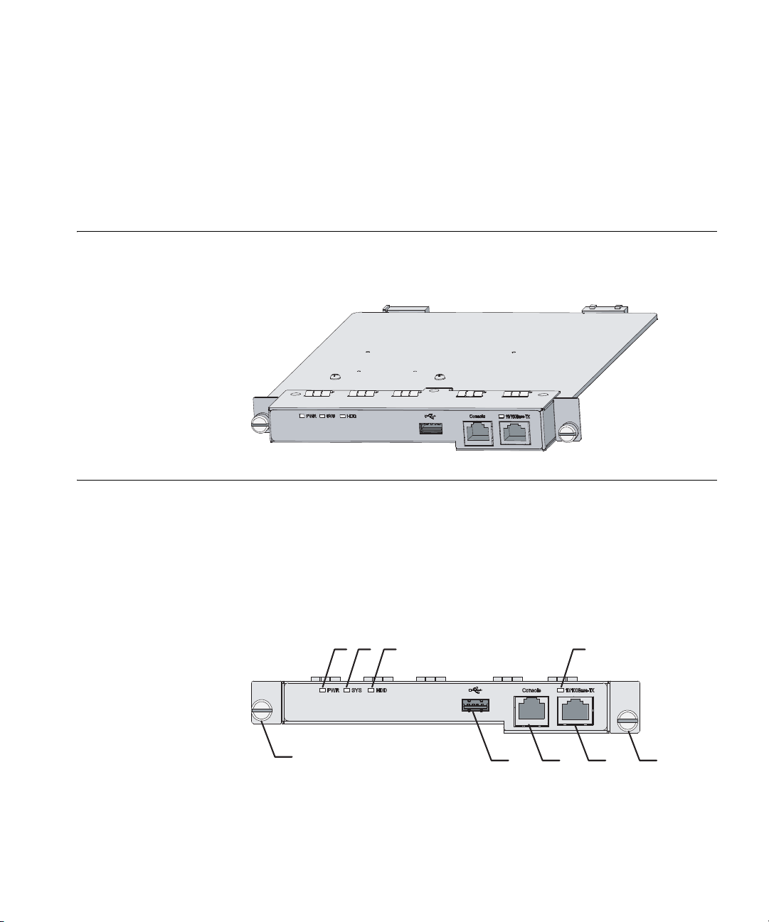
Appearance Figure 1 displays the front view of the OSN|M.
Figure 1 OSN|M appearance
Appearance 9
Front Panel This section describes the OSN|M’s front panel.
Front Panel View An OSN|M provides one USB 2.0 interface, one console port, and one
10/100 Base-TX management Ethernet port. Figure 2 illustrates the front
panel of an OSN|M.
Figure 2 OSN|M front panel
(1) PWR LED (2) SYS LED
(3) HDD LED (4) LED for the management Ethernet port
(5) Captive screw (6) 10/100 Base-TX management Ethernet port
(7) Console port (8) USB 2.0 interface
Page 10

10 Chapter 2: OSN|M Hardware Overview
LEDs There are PWR, SYS, HDD, and management Ethernet port LEDs on the
front panel of an OSN|M. Table 1 describes the four LEDs.
Tab le 1 The OSN|M front panel’s LED descriptions
LED Color Status Function
PWR Green Green, solid
SYS Green/Red Green, solid
HDD Green Green,
LED for the
management
Ethernet port
ON
Green,
blinking
OFF The module is powered off.
ON
Red, solid ON CPU bus fails.
OFF CPU runs normally.
blinking
OFF Hard disk does not perform any
Green/Yellow Green, solid
ON
Green,
blinking
Yellow, solid
ON
Yellow,
blinking
OFF No connection is established.
Normal
The module is being loaded.
CPU bus is busy
Hard disk is reading/writing.
operation.
100-Mbps connection is
established.
100-Mbps connection is
established and data is being
received/transmitted; Active
10-Mbps connection is
established.
10-Mbps connection is
established and data is being
received/transmitted; Active
Interface
Specifications
Console port
The console port on the OSN|M’s front panel conforms to the EIA/TIA-232
asynchronous serial port specifications. You can use the console port to
log into and then configure the OSN|M’s Linux system. Refer to Table 2
for the console port specifications.
Tab le 2 Console port specifications
Specification Description
Connector type RJ45
Number of connectors 1
Page 11

Front Panel 11
Tab le 2 Console port specifications
Specification Description
Interface standard EIA/TIA-232
Cable type Asynchronous serial port cables
Baud rate (bps)
■ 300
■ 1200
■ 2400
■ 4800
■ 9600 (default)
■ 19200
■ 38400
■ 56000
■ 115200
Management Ethernet port
You can use the 10/100Base-TX management Ethernet port on the
OSN|M’s front panel for management only; not for exchanging data. Use
this port to log into the OSN|M’s Linux system through SSH, and then to
configure the Linux system. Refer to Table 3 for the management
Ethernet port specifications.
Tab le 3 Management Ethernet port specifications
Specification Description
Connector type RJ45
Number of connectors 1
Interface standard IEEE 802.3u
Cable type Category 5 cables (forward compatible)
Working mode
Supported frame format
■ Full/half duplex
■ 10/100 Mbps autosensing
■ Ethernet_II
■ Ethernet_SNAP
Page 12

12 Chapter 2: OSN|M Hardware Overview
USB interface
Use the USB interface on the OSN|M’s front panel to connect a storage
medium such as a USB flash disk to perform file related operations. Refer
to Table 4 for the USB interface specifications.
Tab le 4 USB interface specifications
Specification Description
Connector type USB interface
Number of connectors 1
Interface standard USB 2.0 (backward compatible)
Transmit rate
Working mode
■ low-speed mode: 1.5 Mbps
■ full-speed mode: 12 Mbps
■ high-speed mode: 480 Mbps
■ Half duplex
■ Host mode
Hardware Configuration
c
Table 5 describes the hardware components of the OSN|M.
Tab le 5 OSN|M hardware configuration
Specification Description
CPU Celeron M1.0G 373 processor
Memory 512 M
Hard disk 80 G
CAUTION: Do not replace OSN|M hardware components yourself. Doing
so can damage the module.
Table 6 describes the hard disk’s default partitioning.
Tab le 6 Default partitioning of the OSN|M hard disk
Partition
name
/dev/hda1 / ext3 The Linux root file system. When you
Mount
point
Format of
file system Function
choose to boot from the hard disk using
Elilo, it uses this partition as the system’s
root file system. The volume label of this
partition is /.
Page 13

Tab le 6 Default partitioning of the OSN|M hard disk
Hardware Configuration 13
Partition
name
/dev/hda2 /alt ext3 The root file system’s backup partition. Its
/dev/hda3 swap swap The Linux system’s swapping partition.
/dev/hda5 /opt ext The partition provided for the users. It is
/dev/hda6 vboot vfat The Linux system’s boot partition. The
Mount
point
Format of
file system Function
leave-factory setting is null.
When you boot from hard disk using
Elilo, it uses this partition as the system’s
swapping partition.
the system’s largest partition. System,
files are not saved on this partition.
boot loader Elilo can identify the vfat
partition only. The Linux kernel and
ramdisk file are stored on this partition.
Page 14

14 Chapter 2: OSN|M Hardware Overview
Page 15

Installing and Removing the OSN|M 15
3 OSN|M Installation
Installing and Removing the OSN|M
The Switch 5500G supports hot swapping the OSN|M.
c
CAUTION: If the Linux system is running on an OSN|M, use the
poweroff command to exit the system before removing the OSN|M.
Installing an OSN|M in a Switch 5500G
To install the OSN|M, perform the following steps:
1 Put on an ESD-preventive wrist strap and make sure that the
ESD-preventive wrist strap is properly grounded. Then take the OSN|M
out of the package.
2 Unscrew the mounting screws on the switch’s expansion module filler
panel and remove the filler panel.
3 Hold the two sides of the OSN|M front panel with both hands, and slide
in the OSN|M along the guide rails until the OSN|M is fully inserted into
the switch as shown in Figure 3.
4 Use a screwdriver to fasten the fastening screws on both sides of the
OSN|M.
Page 16

16 Chapter 3: OSN|M Installation
(1)
(2)
Figure 3 Install an OSN|M in a switch
(1) Rear panel of the switch (2) Front panel of the OSN|M
Removing the OSN|M
1 Put on an ESD-preventive wrist strap and ensure that the ESD-preventive
wrist strap is properly grounded.
2 Loosen the fastening screws on both sides of the OSN|M using a
screwdriver.
3 Hold the two sides of the OSN|M front panel with both hands and draw
back the module until the module is fully separated from the switch.
CAUTION:
c
■ Hold the two sides rather than the middle of the OSN|M front panel to
install or remove the OSN|M. Otherwise, the OSN|M may be out of
shape.
■ Do not apply excessive force to install or remove an OSN|M, and do
not touch the surface-mounted components directly with your hands.
■ After removing an OSN|M, if no new module is to be installed, install
the filler panel in time to prevent dust and ensure normal ventilation
in the switch.
Page 17

Connecting the Management Ethernet Port Cable 17
Connecting the Management Ethernet Port Cable
c
To connect the management Ethernet port cable, perform the following
steps:
CAUTION: When connecting the cable, pay attention to the mark on the
interface to insert it in the correct direction, otherwise, you may damage
the interface or the OSN|M.
1 Connect the management Ethernet port to a terminal.
■ If the terminal to be connected is a PC or router, use a crossover cable
to connect the management Ethernet port to an Ethernet port of the
PC or router.
■ If the terminal to be connected is a HUB or switch, use a standard
cable to connect the management Ethernet port to an Ethernet port
of the HUB or switch.
2 Power on the OSN|M and check the LED for the management Ethernet
port on the OSN|M’s front panel. ON means a link is present. OFF means
no link is present. If the LED is OFF, check the line for the cause.
Page 18

18 Chapter 3: OSN|M Installation
Page 19

4 Logging Into the OSN|M
Linux System
Login Options You can log into the OSN|M Linux system through:
■ The OSN|M’s console port.
■ The OSN|M’s management Ethernet port using SSH.
■ The OSN|M’s internal service interface using SSH
■ A serial port redirection after you log into the switch. You can connect
to the switch’s OSN|M or to another switch’s (within the same fabric)
OSN|M to which you have logged in through a CLI.
After you connect to the OSN|M’s Linux system, you need to input the
correct username and password. The default username and password are
both root.
Login Options 19
Logging In Through the Console Port
In this example, a PC acts as a terminal. Connect the terminal’s serial port
to the OSN|M’s console port through the configuration cable.
1 Connect the configuration cable’s DB-9 female connector to the PC’s
serial port, and the cable’s RJ-45 connector to the OSN|M’s console port.
2 Start the PC and run a terminal emulation program such as the Windows
HyperTerminal. Select the connection mode COM and set the following
terminal parameters:
■ Bits per second: 9600
■ Data bits: 8
■ Parity: none
■ Stop bits: 1
■ Flow control: None
You can now power on the OSN|M and log into its Linux system through
the PC’s terminal emulation program.
Page 20

20 Chapter 4: Logging Into the OSN|M Linux System
Logging In Through the OSN|M Management Ethernet Port Using SSH
Configuration
Example
The SSH server function is enabled on the OSN|M by default. You can use
SSH on the SSH client to log into the Linux system through the OSN|M’s
management Ethernet port performing the following steps:
1 Connect one end of the cable to the switch’s Ethernet port and the other
end to the OSN|M’s management Ethernet port.
2 Power on the OSN|M and log into the OSN|M’s Linux system by executing
the ssh2 command on the switch. The management Ethernet port’s
default IP address is 192.168.0.2/24.
# Create a VLAN interface on the switch and assign it an IP address. The
IP address is used as the SSH client address to connect the SSH server.
<sysname> system-view
[sysname] interface vlan-interface 1
[sysname-Vlan-interface1] ip address 192.168.0.56 255.255.255.0
[sysname-Vlan-interface1] quit
# Establish the SSH connection to the SSH server (OSN|M) 192.168.0.2.
[sysname]ssh2 192.168.0.2
Username:
# Enter the username and password. The default username and password
are both root.
Username: root
Trying 192.168.0.2 ...
Press CTRL+K to abort
Connected to 192.168.0.2 ...
The Server is not authenticated. Do you continue access it?(
Y/N):y
Do you want to save the server’s public key?(Y/N):y
Enter password:
Last login: Sun Jan 2 11:48:42 2005 from 192.168.0.56
[root@localhost ~]#
You have logged into the Linux system and can configure and manage
that system.
Page 21

Logging In Through the OSN|M Internal Service Interface Using SSH 21
SSH client
10 . 10 . 10 . 1 / 24
Switch with OSN|M
GE 1 / 1 / 2
Eth 1
10 . 10 . 10 . 6 / 24
GE1/0/2 on the switch
Internal connection
between the OSN|M and the switch
Logging In Through the OSN|M Internal Service Interface Using SSH
n
Configuration
Example
After you install the OSN|M into the Switch 5500G’s expansion module
slot, the OSN|M exchanges information with the switch through its two
internal service interfaces, which display as Eth0 and Eth1 in the Linux
system.
The Switch 5500G provides two internal ports GigabitEthernet 1/1/1 and
GigabitEthernet 1/1/2 to connect with Eth0 and Eth1. Eth1 can be used
as an external interface when the OSN|M serves as the SSH server. The
default IP address of Eth1 is 10.10.10.6/24.
As shown in Figure 4, you can connect an SSH client with the OSN|M
resident switch or another switch in the fabric containing the OSN|M
resident switch, and then use SSH to log into the OSN|M’s Linux system
through the OSN|M’s Eth1 interface.
A Switch 5500G Ethernet switch provides two internal ports,
GigabitEthernet 1/1/1 and GigabitEthernet 1/1/2, to connect to the
OSN|M. Do not perform any configuration except to disable the Spanning
Tree Protocol (STP) on GigabitEthernet 1/1/1, and do not perform any
configuration on GigabitEthernet 1/1/2 except to allow a VLAN to pass.
Network diagram
Figure 4 Logging in through the OSN|M’s internal service interface Eth1 using
SSH
Page 22

22 Chapter 4: Logging Into the OSN|M Linux System
Configuration procedure
1 Ensure network connectivity between the SSH client and the OSN|M’s
Eth1 interface.
2 Configure the SSH client’s IP address and that of the Eth1 interface to be
on the same network segment. The IP address of Eth1 is 10.10.10.6/24
by default.
3 Add the following two switch ports to the same VLAN:
■ The port connected with SSH client, GigabitEthernet 1/0/2 in this
example.
■ The port connected with OSN|M’s Eth1, GigabitEthernet 1/1/2 in this
example.
After completing the above configuration, run the SSH client program on
the SSH client, and input the IP address of Eth1 as the SSH server address.
You can log into the OSN|M’s Linux system after the connection is
established.
Logging In through a Switch 5500G Command Line Interface
n
Configuration
Example
You can log into a switch through a console port or an Ethernet port,
then connect to the switch’s OSN|M or to another switch’s (in the same
fabric) OSN|M. In this case, if the Linux system on the OSN|M is running,
the control terminal interface on the switch will switch from the
command line interface (CLI) to the Linux system operating interface.
After the switchover, you can return to the CLI of the switch using the
shortcut key Ctrl+K.
To connect to the OSN|M’s Linux system, use the
OSM connect unit unit-id
command. This command is available in user view.
■ For instructions on configuring the OSN|M on a switch, refer to 3Com
Switch 5500G OSN|M Configuration and Command Reference Guide.
■ If you load services software on the OSN|M, you need to enable
certain protocols such as the Application Control Forwarding Protocol
(ACFP) and ACSEI for information interaction on the OSN|M resident
switch. For details, refer to 3Com Switch 5500G OSN|M Configuration
and Command Reference Guide.
# On the switch, use the osm connect command to connect to the
OSN|M’s Linux system.
Page 23

Logging In through a Switch 5500G Command Line Interface 23
<Sysname> osm connect unit 1
Connected to OSM !
Fedora Core release 6 (Zod)
Kernel 2.6.18.8 on an i686
localhost.localdomain login:
# Enter the username and password. The default username and password
are both root.
localhost.localdomain login: root
Password:
Last login: Sun Jan 2 12:52:22 on ttyS1
[root@localhost ~]#
You have logged into the Linux system and can now configure and
manage the system.
Page 24

24 Chapter 4: Logging Into the OSN|M Linux System
Page 25

BIOS Menu
BIOS Menu 25
5 Understanding and Using
the BIOS Options
Entering the BIOS
Menu
When the OSN|M is powered on, the following information is displayed:
*************************************************
**
* BIOS , Ver 1.17 *
**
*************************************************
Copyright(c) 2005-2007 by 3Com Corporation.
Compiled date: Nov 22 2007 13:47:17
CPU type : Intel(R) Celeron(R) M processor
CPU L1 Cache : 32KB
CPU L2 Cache : 512KB
CPU Clock Speed : 1000MHz
Memory Type : DDR2
Memory Size : 512MB
Memory Speed : 400MHz
BIOS Size : 1024KB
Hard Disk Size : 80GB
HardWare Version is 1.00
Press CTRL-D in 5 seconds to enter BIOS Menu...
To enter the BIOS menu, press Ctrl+D when Press Ctrl-D to enter
BIOS Menu...
appears.
If you are logged into the OSN|M’s Linux system, you can execute the
reboot command to reboot the OSN|M, and then press Ctrl+D when
Press Ctrl-D to enter BIOS Menu... appears to enter the BIOS
menu.
[root@localhost ~]# reboot
If the Linux system is shut down, the following information is displayed:
INIT: Sending processes the TERM signal
INIT: Sending processes the KILL signal
Page 26

26 Chapter 5: Understanding and Using the BIOS Options
Shutting down smartd: [ OK ]
Stopping yum-updatesd: [FAILED]
Stopping atd: [ OK ]
Stopping cups: [ OK ]
Shutting down console mouse services: [ OK ]
Stopping sshd: [ OK ]
Shutting down sm-client: [ OK ]
Shutting down sendmail: [ OK ]
Stopping acseic-daemon: [ OK ]
Stopping acpi daemon: [ OK ]
Stopping crond: [ OK ]
Shutting down RPC idmapd: [ OK ]
Stopping autofs: Stopping automount: [ OK ]
[OK]
Stopping system message bus: [ OK ]
Stopping NFS statd: [ OK ]
Stopping portmap: [ OK ]
Stopping PC/SC smart card daemon (pcscd): [ OK ]
Shutting down kernel logger: [ OK ]
Shutting down system logger: [ OK ]
Shutting down hidd: [ OK ]
Stopping Bluetooth services: [ OK ]
Shutting down interface eth0: [ OK ]
Shutting down interface eth1: [ OK ]
Shutting down interface eth2: [ OK ]
Shutting down loopback interface: [ OK ]
Starting killall: [ OK ]
Sending all processes the TERM signal...
Sending all proc
Saving random seed:
Syncing hardware clock to system time
Turning off quotas:
Unmounting pipe file systems:
Unmounting file systems:
Please stand by while rebooting the system...
Synchronizing SCSI cache for disk sdb:
Synchronizing SCSI cache for disk sda:
ACPI: PCI interrupt for device 0000:01:00.1 disabled
ACPI: PCI interrupt for device 0000:01:00.0 disabled
Restarting system.
.
After waiting for several seconds, the system starts the BIOS and displays
the boot information.
Page 27

Booting the Linux System 27
BIOS Menu Options Press Ctrl+D when Press Ctrl-D to enter BIOS Menu... appears, and
the system displays the BIOS menu.
<1> Boot Linux From HardDisk
<2> Boot Linux From USB
<3> Install Linux OS With Ethernet
<4> Enter Internal Shell
<5> Reboot
Enter your choice(1-5):
Table 7 describes the menu options.
Tab le 7 BIOS menu
Menu item Description
<1> Boot Linux From HardDisk Read the boot program from hard disk
<2> Boot Linux From USB Read the boot program from the storage
<3> Install Linux OS With Ethernet Install the Linux system through Ethernet
<4> Enter Internal Shell Enter the Internal Shell command line.
<5> Reboot Reboot the OSN|M.
and then boot the Linux system.
medium connected to the USB interface,
and then boot the Linux system.
Booting the Linux System
Booting the Linux
System from the Hard
Disk
This section describes the BIOS menu boot options
The system boots the Linux system from the hard disk in the following
conditions:
■ During the BIOS boot process, if you do not perform an operation
within five seconds.
■ During BIOS boot process, if you do not select an option but press
Enter, the system operates according to menu item 1 (booting the
Linux system from hard disk).
■ If you enter 1 at the BIOS menu, the BIOS reads the boot program
from the hard disk to boot the Linux system.
Page 28

28 Chapter 5: Understanding and Using the BIOS Options
Booting the Linux
System from the USB
Storage Medium
Installing the Linux System through an Ethernet Connection
If you enter 2 in the BIOS menu, the BIOS reads the boot program from
the storage medium connected to the USB interface to boot the Linux
system.
This function provides a shortcut to rapid system restoration. You can
backup part of the system installation files into an external storage
medium, such as a USB flash disk. When the system cannot be started
normally due to system kernel file damage, you can use the backup
system files stored in the external storage medium to boot the Linux
system, and then enter the Linux system to locate the problem.
The files that you need to back up include: Initrd, bzImage, and elilo.efi.
For a detailed description of these files, refer to Table 8 on page 30.
If you enter 3 in the BIOS menu, the system installs the Linux system
through the Ethernet port. This option downloads the Linux system files
from a server to the OSN|M for installation. During the installation
process, the OSN|M’s hard disk is formatted and partitioned, and
therefore, the original data on the hard disk is lost. Make sure to use the
Ethernet installation function with caution. The OSN|M module supports
address auto-configuration through DHCP.
Network Diagrams Install an OSN|M in a Switch 5500G. The controller can enter the BIOS
menu of the OSN|M using several methods to execute the Ethernet
installation of the Linux system. Figure 5 shows the network diagram and
installation process for an Ethernet installation. In this example, the
controller logs into the OSN|M module through the console port install
the Linux system using an Ethernet connection. You can install the Linux
system through the two network cards on the OSN|M module.
Figure 5 showns an Ethernet installation through the internal interface
Eth1 on the OSN|M module.
Page 29

Installing the Linux System through an Ethernet Connection 29
Figure 5 Network diagram for an Ethernet installation through Eth1
Internal connection
between the OSN|M and the switch
TFTP Server
DHCP Server
Figure 6 Network diagram for Ethernet installation through the management
Ethernet port Eth2
TFTP Server
IP network
IP network
GE 1 / 0 / 2
on switch
Management
Ethernet port
( Eth 2 ) on OSN|M
GE 1 / 1 / 2
Switch with OAP
Switch with OSN|M
Eth 1
Console
on OSN|M
Console
on OSN|M
Controller
Controller
Configuring the TFTP
Server
DHCP Server
Complete the following configuration procedure on the TFTP server:
1 Ensure that there is network connectivity between the TFTP server and the
switch installed with the OSN|M module.
2 Enable TFTP on the TFTP server, and store the configuration file and the
installation files listed in Table 8 on the TFTP server. (These files are
Page 30

30 Chapter 5: Understanding and Using the BIOS Options
available with the software releases.) Create a directory named
3CR17280-72 on the server, and put the configuration file in this
directory.
Tab le 8 The Linux system installation files
File name Description
Initrd The ramdisk file generated by busybox.
bzImage The kernel file generated by busybox.
elilo.efi Linux boot loader
elilo.conf ELILO configuration file
disk.tar.gz Mirror image file of the hard disk
Vfat.tar.gz Kernel file of the Linux system, needs to
3 Modify the contents of the configuration file. The configuration file is
used to boot the system and download the required installation files. The
configuration file contains the names and paths of the installation files on
the TFTP server, for example:
■ BZIMAGEFILE=setup/1.06/bzimage
be stored on the vfat partition.
■ INITRDFILE=setup/1.06/initrd
■ ELILOEFIFILE=setup/1.06/elilo.efi
■ DISKFILE=setup/1.06/disk.tar.gz
■ VFATFILE=setup/1.06/vfat.tar.gz
In each of the above examples, on the right of the equal sign, the path
for the installation file stored on the TFTP server is displayed. Make the
relevant modifications based on the TFTP server’s configuration.
Caution:
c
■ The configuration file is in UNIX format.
■ Put the configuration file in the directory called 3CR17280-72.
■ Make sure that the path for the installation files in the configuration
file is consistent with that on the TFTP server.
■ In the configuration file, the equal sign and the content on the left
cannot be modified.
4 Modify the name of the configuration file. The OSN|M module
automatically matches the configuration file according to its MAC
Page 31

Installing the Linux System through an Ethernet Connection 31
address and IP address. For example, when obtaining the configuration
file from the TFTP server, the OSN|M module with the IP address
10.10.10.1 and MAC address 00-00-12-34-56-79 matches the
configuration file in the following order:
a Searches file 01-00-00-12-34-56-79 under directory \3CR17280-72;
b If no such file is found, searches file 0A0A0A01 (0A0A0A01 is the
hexadecimal format of the IP address of the OAP module);
c If no such file is found, searches file 0A0A0A0;
d If no such file is found, searches file 0A0A0A;
e If no such file is found, searches file 0A0A0;
f If no such file is found, searches file 0A0A;
g If no such file is found, searches file 0A0;
h If no such file is found, searches file 0A;
i If no such file is found, searches file 0;
j If no such file is found, searches file default (the default configuration
file).
Configuring the DHCP
Server
With the above matching process, you can manage the configuration
files in a hierarchical way based on the actual networking. For example,
the network segment 10.10.0.0/16 uses the configuration file 0A0A; the
network segment 10.10.10.0/24 uses the configuration file 0A0A0A; the
device with the IP address 10.10.10.1/26 uses the configuration file
0A0A0A01.
To configure the DHCP server, perform the following steps:
1 A DHCP server can assign an IP address for the client dynamically.
2 You are required to configure the IP address of the TFTP server on the
DHCP server for the OAP module to download the configuration file. The
configuration method and priority are as follows:
a If Next server IP address is configured for the DHCP server, it is taken
as the IP address of the TFTP server;
b If no Next server IP address is configured for the DHCP server, but TFTP
Server Name (Option 66) is configured, TFTP Server Name is taken as
the address of the TFTP server;
Page 32

32 Chapter 5: Understanding and Using the BIOS Options
c If neither Next server IP address nor TFTP Server Name (Option 66) is
configured for the DHCP server, the OAP module considers that the
DHCP server can also serve as the TFTP server, and takes the IP address
of the DHCP server as the IP address of the TFTP server.
3 The following example shows the DHCP server’s configuration file’s
content. Configure the DHCP server on the Linux system, and the content
of the configuration file on the DHCP server as follows:
ddns-update-style interim;
ignore client-updates;
subnet 10.10.10.0 netmask 255.255.255.0 {
range dynamic-bootp 10.10.10.20 10.10.10.100;
default-lease-time 21600;
max-lease-time 43200;
filename "pxelinux.0";
#option tftp-server-name "10.10.10.1";
next-server 10.10.10.1;
}
Ethernet Installation
Procedures
c
disk is formatted and partitioned, and therefore the original data on the
hard disk is lost. Make sure to use the Ethernet installation function with
caution.
1 Enter the BIOS menu (for detailed procedures, refer to “BIOS Menu
Options” on page 27), and select 3 to select Ethernet installation.
CAUTION: During the Linux system Ethernet installation, the OSN|M hard
<1> Boot Linux From HardDisk
<2> Boot Linux From USB
<3> Install Linux OS With Ethernet
<4> Enter Internal Shell
<5> Reboot
Enter your choice(1-5):3
The system automatically connects to the DHCP server to obtain its own
IP address as well as the TFTP IP address. It then connects to the TFTP
server to download configuration and installation files. It then loads the
kernel and ramdisk files. The / # prompt indicates that the file loading is
complete.
2 When / # appears, type the command
pxe_install and press Enter to
execute the Ethernet installation script. The installation process takes
about 20 minutes and displays the following messages as it proceeds.
Page 33

Installing the Linux System through an Ethernet Connection 33
/ # pxe_install
Try to do network install on eth1.....
Get the ip address from dhcp-server.....
udhcpc (v1.6.0) started
Sending discover...
Sending select for 10.10.10.91...
Lease of 10.10.10.91 obtained, lease time 21600
Get TFTP server IP address from DHCP by NextServer
The TFTP server IP address is: 10.10.10.10
Get config file setup/3CR17280-72/01-00-00-12-34-56-7
9.....Fail
Get config file setup/3CR17280-72/0A0A0A5B.....Fail
Get config file setup/3CR17280-72/0A0A0A5.....Fail
Get config file setup/3CR17280-72/0A0A0A.....OK
fdisk harddisk.....OK
mkfs of sda1.....OK
mkfs of sda2.....OK
mkfs of sda3.....OK
mkfs of sda5.....OK
mkfs of sda6.....OK
download vfat file(1.06/vfat.tar.gz).....OK
decompress vfat file(vfat.tar.gz).....OK
download disk file(1.06/disk.tar.gz).....OK
decompress disk file(disk.tar.gz).....OK
install hard disk OK
install completed
/ #
3 After the installation, execute the reboot command to reboot the
OSN|M:
/ # reboot
Do not interrupt the system while it is booting; until the following
messages appear.
Fedora Core release 6 (Zod)
Kernel 2.6.18.8 on an i686
localhost.localdomain login:
4 Enter the username and password to log into the Linux system.
A complete Linux file system is installed on the hard disk.
The first time you boot the system after an Ethernet installation, file
n
system checking occurs, which consumes more time than usual. Make
sure to wait until all system checking is complete before continuing.
Page 34

34 Chapter 5: Understanding and Using the BIOS Options
Entering the Internal Shell Command Line
n
n
After the kernel file and ramdisk file are loaded, the system prompts / #.
In this case, you can use the fdisk command to view the Linux file system
and to perform file operations or manually update system files. System
restoration or upgrades in this way does not result in reformatting the
hard disk.
Enter 4 in the BIOS menu to enter the Internal Shell command line.
Enter your choice(1-5):4
Shell>
You now have administrator rights and can perform file system
operations on the hard disk’s files.
Operations performed through the Internal Shell command lines may
affect the normal working of other items. 3Com recommends that you
do not to log into and use this system.
You can use the
Shell> reset
After executing the reset command, the system reboots the BIOS.
reset command to exit the Internal Shell command line.
Upgrading the BIOS After entering the Internal Shell command line, you can use the
command in Table 9 to upgrade the BIOS:
Tab le 9 Upgrading the BIOS
To … Use the command… Remarks
Upgrade the BIOS bios update -s { eth1 | eth2 }
local-host-IP-address
TFTP-server-IP-address
btm-file-name
You can use the bios update -s eth1 command to use the interface Eth1
on the OSN|M module that connects the switch to upgrade the BIOS, or
use the bios update -s eth2 command to use the management Ethernet
port (Eth2) on the front panel of the ONS|M module to upgrade the BIOS.
local-host-IP-address: IP address of the selected interface on the ONS|M
module, that is, the IP address of Eth1 or Eth2.
Required
Page 35

Upgrading the BIOS 35
Switch with an OSN|M
TFTP Server
Controller
GE1/0/2 on the switch
GE1/1/2
Eth1
10 .10 .10 .1/ 24
OSN|M Console
Internal connection
between the OSN|M and the switch
10.10.10.10/24
TFTP-server-IP-address: IP address of the TFTP server selected.
btm-file-name: Name of the installation file (a .btm file).
The TFTP server and the selected ONS|M interface must be on the same
network segment.
Upgrading the BIOS
Through Interface
Eth1
Network diagram
Install the ONS|M module in a Switch 5500G. You can log in to the Linux
system of the ONS|M module to enter the Internal Shell command line
and upgrade the BIOS using one of several methods. The example in
Figure 7 shows the network diagram for installing and upgrading the
BIOS. To follow this example, log into the ONS|M module through the
console port to perform BIOS upgrade through Eth1.
Figure 7 Network diagram for upgrading the BIOS through Eth1
Configuration procedure
# Use linux-bios117.BTM command to upgrade the BIOS through Eth1.
Shell> bios_update -s eth1 10.10.10.1 10.10.10.10
linux-bios117.BTM
Please wait! Loading.........done!
Erasing Flash ............................... .........done!
Writing flash
..........................................done!
Update BIOS from file linux-bios117.BTM success!
Shell>
Page 36

36 Chapter 5: Understanding and Using the BIOS Options
Switch with an OSN|M
Controller
Management Ethernet
port (Eth2) on an OSN|M
10.10.10.1/24
Console on the
OSN|M
10.10.10.10/24
After completing the BIOS upgrade, you can use the reset command to
exit the Internal Shell command line and restart the BIOS.
Upgrading BIOS
Through Eth2
Network diagram
Install the OAP module in an S5600 switch. Controller can log in to the
Linux system of the OAP module to enter the Internal Shell command line
to upgrade the BIOS in many ways. The following exemplifies the
network diagram and installation process of BIOS upgrade. In this
example, Controller logs in to the OAP module through the console port
to perform BIOS upgrade through Eth2.
Figure 8 Network diagram for upgrading the BIOS through Eth2
Configuration procedure
# Use linux-bios117.BTM to upgrade the BIOS through Eth2.
Shell> bios_update -s eth2 10.10.10.1 10.10.10.10
linux-bios117.BTM
Please wait! Loading.........done!
Erasing Flash ............................... .........done!
Writing flash
..........................................done!
Update BIOS from file linux-bios117.BTM success!
Shell>
After completing the BIOS upgrade, you can use the reset command to
exit the Internal Shell command line and restart the BIOS.
 Loading...