

Page 1

User Guide
Gigabit Server Network Interface Cards
3C996B-T and 3C996-SX
http://www.3com.com/
http://support.3com.com/registration/frontpg.pl
Published November 2001
User guide version 1.0.2
Page 2

3Com Corporation■5400 Bayfront Plaza■Santa Clara, California■95052-8145■U.S.A.
Copyright © 2001 3Com Corporation. All rights reserved. No part of this documentation may be reproduced in any form or by any means or used to
make any derivative work (such as translation, transformation, or adaptation) without written permission from 3Com Corporation.
3Com Corporation reserves the right to revise this documentation and to make changes in content from time to time without obligation on the part
of 3Com Corporation to provide notification of such revision or change.
3Com Corporation provides this documentation without warranty, term, or condition of any kind, either implied or expressed, including, but not
limited to, the implied warranties, terms or conditions of merchantability, satisfactory quality, and fitness for a particular purpose. 3Com may make
improvements or changes in the product(s) and/or the program(s) described in this documentation at any time.
If there is any software on removable media described in this documentation, it is furnished under a license agreement included with the product as
a separate document, in the hard copy documentation, or on the removable media in a directory file named LICENSE.TXT or !LICENSE.TXT. If you are
unable to locate a copy, please contact 3Com and a copy will be provided to you.
UNITED STATES GOVERNMENT LEGEND
If you are a United States government agency, then this documentation and the software described herein are provided to you subject to the
following:
All technical data and computer software are commercial in nature and developed solely at private expense. Software is delivered as “Commercial
Computer Software” as defined in DFARS 252.227-7014 (June 1995) or as a “commercial item” as defined in FAR 2.101(a) and as such is provided
with only such rights as are provided in 3Com’s standard commercial license for the software. Technical data is provided with limited rights only as
provided in DFAR 252.227-7015 (Nov 1995) or FAR 52.227-14 (June 1987), whichever is applicable. You agree not to remove or deface any portion
of any legend provided on any licensed program or documentation contained in, or delivered to you in conjunction with, this user guide.
Portions of this documentation are reproduced in whole or in part with permission from (as appropriate).
Unless otherwise indicated, 3Com registered trademarks are registered in the United States and may or may not be registered in other countries.
3Com, DynamicAccess, EtherCD, EtherLink and EtherLink II are registered trademarks and the 3Com logo is a trademark of 3Com Corporation.
Intel and Pentium are registered trademarks of Intel Corporation. Microsoft, Windows, and Windows NT are registered trademarks
of Microsoft Corporation. Novell and NetWare are registered trademarks of Novell, Inc. UNIX is a registered trademark in the United States and other
countries, licensed exclusively through X/Open Company, Ltd.
All other company and product names may be trademarks of the respective companies with which they are associated.
Page 3

Contents
1
2
Introduction
Contents 1
Advanced Server Features Overview 1
Load Balance 2
Advanced Server Features for Windows 2000 2
Advanced Server Features for Windows NT 3
Advanced Server Features for Novell NetWare 3
Advanced Server Features for Linux 4
3Com Management Programs 4
Creating a Driver Disk 5
Installing and Connecting the NIC
System Requirements 7
Windows XP (64-bit) 7
Windows XP (32-bit) 7
Windows 2000 7
Windows NT 7
NetWare 8
Linux 8
UNIX 8
Solaris 8
Safety Precautions 9
Pre-Installation Checklist 9
Installing and Connecting the NIC 10
Installing the NIC 10
Connecting the Network Cables 12
Installing and Using the 3Com Connection Assistant 13
System Requirements 13
Installation 13
3
Windows XP Driver Setup
Installing the Driver Software 15
Windows XP 32-bit 15
Windows XP 64-bit 16
Driver Installation Without Master Navigator 16
Verifying Successful Installation 17
Modifying Configuration Parameters 17
Removing the Driver Software 19
Installing Advanced Server Features 19
Uninstalling Advanced Server Features 20
Configuring Advanced Server Features 20
Configuring Teaming 20
Configuring VLANs 22
Advanced Server Control Suite 23
Page 4

Contents
4
Windows 2000 Driver Setup
Installing the Driver Software 25
Verifying Successful Installation 27
Modifying Configuration Parameters 27
Removing the Driver Software 29
Installing Advanced Server Features 30
Uninstalling Advanced Server Features 30
Configuring Advanced Server Features 30
Configuring Teaming 30
Configuring VLANs 32
Advanced Server Control Suite 34
Updating Mini-port (Core) Drivers 34
5
Windows NT Driver Setup
Installing the Driver Software 37
Modifying Configuration Parameters 38
Updating the Driver Software 40
Removing the Driver Software 40
Installing Advanced Server Features 41
Uninstalling Advanced Server Features 41
Configuring Teaming 42
Configuring VLANs 44
Advanced Server Control Suite 45
Installing the Microsoft Loopback Adapter Driver 46
Performing a Fresh Installation of Windows NT on a
Backup Domain Controller 46
Setting up SERVER 2 47
Stopping the Net Logon Service on SERVER 1 48
Stopping the Net Logon Service on SERVER 2 48
Renaming Domain-2/SERVER-2 to DOMAIN-1/SERVER-2 48
Updating Mini-port (Core) Drivers 49
6
Novell NetWare Driver Setup
Pre-Installation Requirements 51
Installing Novell NetWare Server 4.2 51
Installing Novell NetWare Server 5.1 54
Verifying or Modifying NIC Parameters 54
Removing Drivers from Autoexec.ncf 55
Installing Advanced Server Features 56
Uninstalling Advanced Server Features 56
Load Balance and Trunk Mode Selection 57
Loading Frame Types 57
Hot Standby 57
Configuring VLANs 57
Additional Command Line Keywords 59
Editing the AUTOEXEC.NCF File 59
Installing Advanced Server Features on Novell NetWare Server 4.2 and 5.1 63
NIC Driver Configuration Parameters for Novell NetWare 64
Page 5

7
Linux Driver Setup
Installation Overview 65
Installing the Source RPM Package 65
Building the Driver From a TAR File 65
Patching PCI Files (Optional) 66
Unloading and Removing the Driver 66
Optional Parameters 66
Advanced Server Features 67
Installing Advanced Server Features 68
Configuring Teams 69
8
UNIX and
SCO OpenServer Driver Setup
UnixWare 7 Driver 75
Package Creation 75
Driver Installation 75
MAC Address 76
Jumbo MTU Size 76
SCO OpenServer Release 5 Driver 76
Installation Diskette 76
Driver Installation 77
Jumbo Frames and Other Advanced Parameters 77
Contents
9
Solaris Driver Setup
Driver Installation 79
Uninstalling the Driver 79
Customizing the Driver Configuration 80
ForceSpeedDuplex 80
FlowControl 80
MaxJumboFrameSize 81
TxPacketDescCnt 81
RxStdDescCnt 81
RxJumboDescCnt 81
RxCoalescingTicks 81
RxMaxCoalescedFrames 81
TxCoalescingTicks 81
TxMaxCoalescedFrames 82
RxCoalescingTicksDuringInt 82
TxCoalescingTicksDuringInt 82
RxMaxCoalescedFramesDuringInt 82
TxMaxCoalescedFramesDuringInt 82
StatsCoalescingTicks 82
DoubleCopyTxBufferSize 82
ndd Command 83
Page 6

Contents
10
3Com Management Programs
Overview 85
Installing the Management Programs 85
Removing the Management Programs 86
Initializing the Management Programs 86
Vital Sign 86
Diagnostics 87
Cable Analysis 88
Load Balance/Virtual LANs 89
Saving the Configuration 91
Restoring the Configuration 91
Load Balance/Virtual LAN Statistics 91
11
Troubleshooting
Hardware Diagnostics 93
Checking Port LEDs 93
Troubleshooting Checklist 94
Checking if Proper Drivers are Loaded 94
Windows 94
NetWare 95
Linux 95
Running Cable Analysis 95
Length 96
Cable Diagnostics Display 96
Testing Network Connectivity 96
Windows 96
NetWare 96
Linux 97
DOS Diagnostic Failures 97
Wake-on-Lan 97
Known Problems 97
Windows 2000 97
Linux 98
A
Key Protocols and Interfaces
CIM 99
DMI 100
SNMP 100
NIC Teaming 101
Load Balancing 101
Link Aggregation (802.3ad) 101
Generic Link Aggregation (Trunking) 101
Failover Teaming 102
VLANs Overview 102
VLAN Support 102
Page 7

B
Installing and Using the Managed PC Boot Agent
Booting From the Network 105
Using the Boot ROM on the NIC to Boot from the Network 105
Enabling or Disabling the Boot ROM Setting 106
C
Specifications
10/100/1000 BASE-T Cable Specifications 107
Performance Specifications 107
Physical Characteristics 107
Power Requirements 107
Environmental Specifications 108
D
Technical Support
Online Technical Services 109
World Wide Web Site 109
3Com KnowledgeBase Services 109
3Com FTP Site 109
Support from Your Network Supplier 110
Support from 3Com 110
Returning Products for Repair 111
Contents
Regulatory Information
FCC Class A Verification Statement 113
FCC Class B Statement 113
FCC Declaration of Conformity 114
Index
Page 8

Page 9

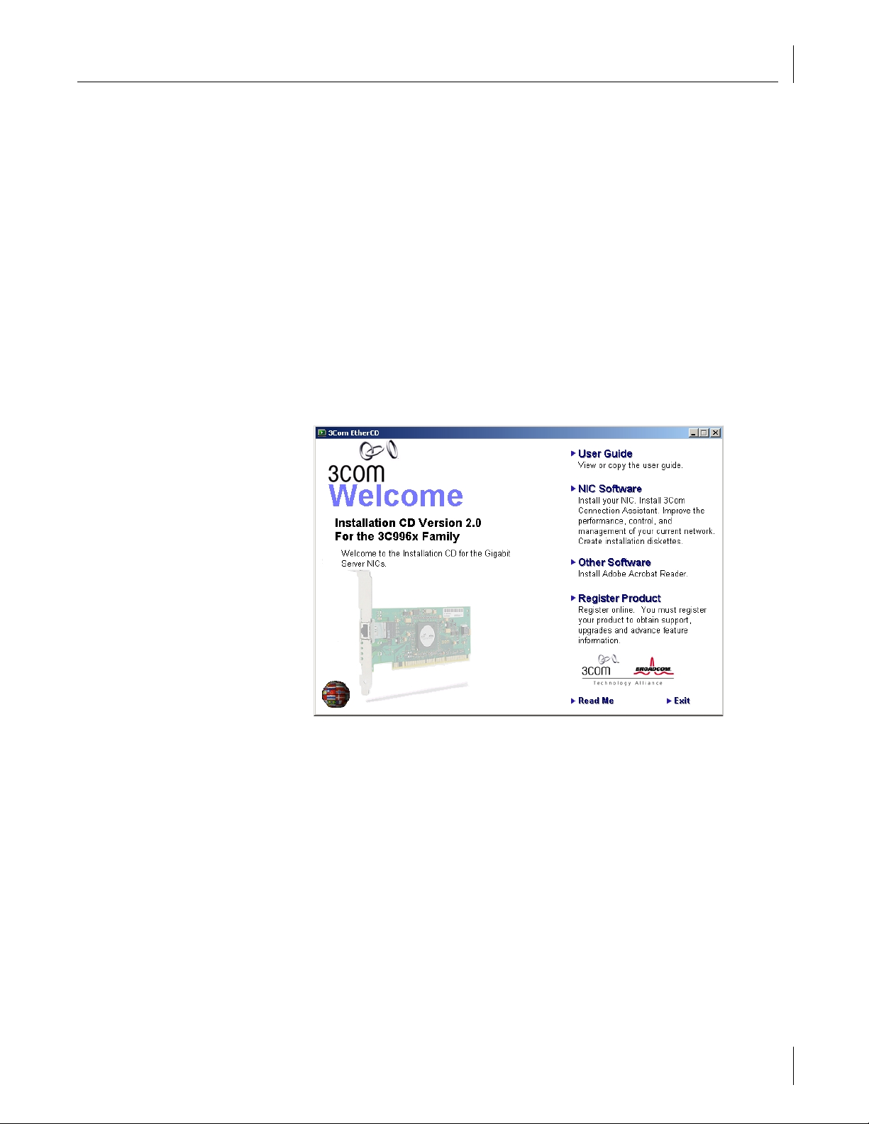
Introduction
1
This guide describes how to install and configure the 3Com® Gigabit Server NICs in
Windows XP, Windows 2000, Windows NT, Novell NetWare, Linux, UNIX, and, Solaris
operating system environments.
Contents
3Com Gigabit Server NIC
■
Keep the NIC in its package until ready for installation.
■
3Com Installation CD
Quick start guide.
■
Inform your network supplier of any missing or damaged items. If you need to return the
NIC, you must use the original (or equivalent) packaging.
Advanced Server Features Overview
The Advanced Server Features program is an intermediate software driver for Windows
2000 Server operating systems (Server, Advanced Server, and Datacenter Server),
Windows NT Server operating systems (Server and Enterprise Server), NetWare, and Linux.
The Advanced Server Features provide load balancing, failover, and VLAN configuration.
These features are provided by creating teams (virtual NICs) that consist of multiple NICs.
A team can consist of one to eight NICs, and each NIC can be designated primary or
standby. All primary NICs in a team will participate in load balancing operations by
sending and receiving a portion of the total traffic. Standby NICs will take over in the
event that all primary NICs have lost their links. VLANs can be added to a team to allow
multiple VLANs with different VLAN IDs. A virtual NIC is created for each VLAN added.
Load balancing and failover features will work with any third-party NIC. VLANs work with
3Com, Broadcom, Alteon, and Intel NICs.
NOTE:
below).
Standby can be used only in load balance mode (see “Load Balance”
with Gigabit Server driver software and online user guide.
1
Page 10

1 Introduction
Load Balance
Load balance is a protocol-specific scheme. The levels of support for IP, IPX, and other
protocols are listed below.
Protocol Load Balancing Failover
IP Yes Yes
IPX Yes* Yes**
Other protocols No Yes**
*Only outbound load-balancing for IPX (on NetWare only).
**For 3Com NICs.
Load balance mode works with all Ethernet switches without configuring the switch ports
to any special trunking mode. Only IP traffic will be load-balanced in both inbound and
outbound directions. IPX traffic will be load-balanced in the outbound direction only.
Other protocol packets will be sent and received through one primary NIC only. Failover
for non-IP traffic is supported using 3Com,Broadcom,Alteon, and Intel NICs. The generic
trunking mode requires the Ethernet switch to support some form of port trunking mode
(for example, Cisco Systems Gigabit EtherChannel or other switch vendors’ link
aggregation mode). This mode is protocol-independent and all traffic should be loadbalanced and fault-tolerant.
Advanced Server Features for Windows 2000
The following options are supported under Windows 2000 Server operating systems
(Server, Advanced Server, Datacenter Server). See “Windows 2000 Driver Setup” on
page 25 for additional information.
Failover and Load Balance
Adapter teaming for failover (heterogeneous support for 3Com 10/100 server NICs,
■
Alteon AceNIC, released Intel 10/100 server NICs, released Intel 1000BaseSX server
NICs, and Intel 82559 LAN on Motherboard [LOM])
Load balance
■
Generic Link Aggregation (GEC/FEC, open trunk)
■
Link aggregation (IEEE 802.3ad) static implementation only
■
Virtual LAN (VLANs)
Up to 64 VLANs per team using IEEE 802.1Q-1988 tagging
■
Offloading
IP, TCP/UDP checksum
■
Support for segmentation of large TCP packets
■
Jumbo frames (9K)
■
Power Management
Remote Wake Up (magic packet, specific pattern)
■
NOTE:
Wake-on-LAN (WOL) is not supported with the fiber version of the
Gigabit Server NIC (3C996-SX). WOL must be disabled when using the fiber
Gigabit Server NIC.
PCI Hot-Plug
Microsoft
■
2
Page 11

Advanced Server Features Overview
Advanced Server Features for Windows NT
The following options are supported under Windows NT Server operating systems
(Server and Enterprise Server). See “Windows NT Driver Setup” on page 37 for additional
information.
Failover and Load Balance
Adapter teaming for failover (heterogeneous support for 3Com 10/100 server NICs,
■
released Alteon AceNIC, Intel 82559 LAN on Motherboard (LOM), released
Intel 10/100 server NICs, and released Intel 1000BaseSX server NICs).
Load balance
■
Generic Link Aggregation (GEC/FEC, open trunk)
■
Link aggregation (IEEE 802.3ad) static implementation only
■
Virtual LAN (VLANs)
Up to 64 VLANs per team using IEEE 802.1Q-1988 tagging.
■
Offloading
Jumbo frames (9K)
■
PCI Hot-Plug
Contact your OEM for more information.
■
Advanced Server Features for Novell NetWare
The following options are supported under Novell NetWare. See “Novell NetWare Driver
Setup” on page 51 for additional information.
Failover and Load Balance
Adapter teaming for failover (heterogeneous support for 3Com 10/100 server NICs,
■
Alteon Tigon2/3, Intel 82559 LAN on Motherboard (LOM), Intel 10/100 server NICs,
and Intel 1000BaseSX server NICs).
Load Balance
■
Generic Link Aggregation (GEC/FEC, open trunk)
■
NESL Compliance
For optimal fault tolerance and recovery operations, BASP.LAN relies on the NIC drivers to
generate NESL (NetWare Event Service Layer) events during link changes and other failure
events. NESL is an optional feature in the ODI driver specification and not all drivers
support it. For NESL events to propagate properly to BASP.LAN, ODINEB.NLM must be
loaded before the NESL compliant ODI drivers.
Do the following to determine if a NIC driver supports NESL events:
Load BASP.LAN and create a team by binding the NIC to the virtual slot (see
■
instructions and examples below). In the Virtual Adapter X Team Members screen
of the BASP.LAN menu interface, the Link status of all bound NICs are shown.
Disconnect or connect the NIC cable. The link status shown on the screen should
change immediately if the NIC driver supports NESL events.
3
Page 12

1 Introduction
Virtual LAN (VLANs)
Up to 64 VLANs per NIC using IEEE 802.1Q-1988 tagging (64 is the maximum
■
configurable, although 32 is the maximum operable).
Offloading
IP, TCP/UDP checksum—NetWare 5.0 or greater only
■
PCI Hot-Plug
Contact your OEM for more information.
■
Advanced Server Features for Linux
The Gigabit Ethernet NIC supports the Linux driver. See “Linux Driver Setup” on page 65
for additional information.
Packaging—The driver has been released in two packaging formats, source RPM and
■
compressed TAR formats.
Module Parameters—Optional parameters for the driver can be supplied as
■
command-line arguments to the insmod command.
Advanced Server Features—A kernel module designed for Linux 2.2 kernel that
■
provides load balancing, failover, and VLAN features.
3Com Management Programs
The 3Com Management Programs is a graphical user interface that functions with the
Windows 2000 Server operating systems (Server, Advanced Server, and Datacenter
Server). See “3Com Management Programs” on page 85 for additional information.
3Com Management Programs have the following features:
Vital Sign—The Vital Sign screen allows you to view vital NIC information, network
■
status, and network connectivity. Active NICs are listed.
Diagnostics—The Diagnostics screen allows you to view information and utilize
■
functions to test this network interface card or LOM.
Cable Analysis—From the Cable Analysis screen the user can monitor conditions of an
■
Ethernet CAT5 cable connection within a cable plant in an Ethernet network. The
software detects various cable conditions such as cable lengths between two given
nodes, cable pair breakage, cable pair polarity, and data skew between cable pairs.
Load Balance/Virtual LANs—The Load Balance/Virtual LANs screen allows you to
■
configure advanced features. Any available NIC can be configured as part of a team.
Statistics—The Statistics screen allows you view traffic statistics for most NICs.
■
Statistical values and coverage are more comprehensive for some NICs than
for others.
4
Page 13
Creating a Driver Disk
Create driver disks using the MakeDisk utility (setup.exe file). This utility will allow you to
create disks with the following drivers:
■
■
■
■
■
■
■
■
■
■
1
Windows XP 32-bit Driver
Windows XP 64-bit Driver
Windows 2000 Driver
Windows NT Driver
NetWare Driver
Advanced Server Features—Windows XP 64-bit Driver
Advanced Server Features—Windows 2000 Driver
Advanced Server Features—Windows NT Driver
Advanced Server Features—NetWare Driver
Advanced Server Features—Linux Driver
Insert the
3Com Installation CD
in the CD-ROM drive. Allow your operating system’s
autorun feature to launch the Master Navigator.
Creating a Driver Disk
Click
2
3
4
5
6
7
NIC Software
Click
Installation Utilities
Click
Create Installation Diskette
In the Welcome window of the Diskette Creation Utility, click
Insert a 3.5” disk into floppy drive A (default) or B. Click
Follow the remaining Diskette Creation Utility commands and insert diskettes when
.
.
.
.
Next
.
Next
prompted. When all driver diskettes have been created, the message “Diskette Copy
Complete” appears on your screen.
Click
8
When all driver diskettes have been created, the information screen will appear,
9
to end the Diskette Creation Utility.
OK
confirming that the drivers were successfully created. Click OK.
5
Page 14

Page 15

Installing and Connecting the NIC
2
System Requirements
Before installing the Gigabit Ethernet NIC, be sure your system meets the requirements
listed for your operating system.
Windows XP (64-bit)
■
■
■
■
■
■
Windows XP (32-bit)
■
■
■
■
■
■
Itanium-based computer that meets Windows XP software requirements
One open 32-bit or 64-bit PCI slot
PCI v2.2 33/66 MHz or PCI-x v1.0 64 bit 133 MHz
256 MB RAM (minimum)
Microsoft Windows XP (64-bit version)
Gigabit Ethernet NIC driver software for Windows XP
Pentium-based computer that meets Windows XP software requirements
One open 32-bit or 64-bit PCI slot
PCI v2.2 33/66 MHz or PCI-x v1.0 64 bit 133 MHz
128 MB RAM (minimum)
Microsoft Windows XP (32-bit version)
Gigabit Ethernet NIC driver software for Windows XP
Windows 2000
Pentium-based computer that meets Windows 2000 software requirements
■
One open 32-bit or 64-bit PCI slot
■
PCI v2.2 33/66 MHz or PCI-x v1.0 64 bit 133 MHz
■
128 MB RAM (minimum)
■
Microsoft Windows 2000 (Server, Advanced Server, or Datacenter Server)
■
Gigabit Ethernet NIC driver software for Windows 2000:
■
Windows NT
Pentium-based computer that meets Windows NT 4.0 software requirements
■
One open 32-bit or 64-bit PCI slot
■
PCI v2.2 33/66 MHz or PCI-x v1.0 64 bit 133 MHz
■
128 MB RAM (minimum)
■
Microsoft Windows NT 4.0 (Server or Enterprise Server) with Service Pack 5 or later
■
Gigabit Ethernet NIC driver software for Windows NT
■
7
Page 16

2 Installing and Connecting the NIC
NetWare
Pentium-based computer that meets Novell NetWare 4.2/5.x/6.x software
■
requirements
One open 32-bit or 64-bit PCI slot
■
PCI v2.2 33/66 MHz or PCI-x v1.0 64 bit 133 MHz
■
128 MB RAM (minimum)
■
One of the following versions of Novell NetWare:
■
Novell NetWare 5.0 or higher, with Support Pack 3 or the most recent NetWare 5
■
Support Pack
Novell NetWare 4.2 with Support Pack 7 or the most recent Support Pack, including
■
the optional ODI v3.31 LAN drivers (MISC/ODI331).
You can get the appropriate updates from the Novell support Web site
Gigabit Ethernet NIC driver software for Novell NetWare. (Note that the server ODI
■
driver can be found at the \netware\driver directory).
Linux
Pentium-based computer that meets Linux software requirements
■
One open 32-bit or 64-bit PCI slot
■
PCI v2.2 33/66 MHz or PCI-x v1.0 64 bit 133 MHz
■
128 MB RAM (minimum)
■
NOTE:
Although the driver should work with many Linux kernel versions and
distributions, it has only been tested on RedHat 6.2 and 7 Linux distributions for
i386 (kernel version 2.2.14 and 2.2.16), and the 2.4.0 test kernel. Furthermore,
the driver has only been tested as a loadable module.
UNIX
Pentium-based computer that meets corresponding UNIX software requirements
■
One open 32-bit or 64-bit PCI slot
■
PCI v2.2 33/66 MHz or PCI-x v1.0 64 bit 133 MHz
■
128MB RAM (minimum)
■
Solaris
Pentium-based computer that meets Solaris 8 software requirements
■
One open 32-bit or 64-bit PCI slot
■
PCI v2.2 33/66 MHz or PCI-x v1.0 64 bit 133 MHz
■
128MB RAM (minimum)
■
Solaris 8 operating system
■
8
Page 17

Safety Precautions
Observe the following safety precautions.
WARNING:
can be lethal. Before you remove the cover of your system, you must observe the
following precautions to protect yourself and to prevent damage to the system
components.
■
■
■
■
Pre-Installation Checklist
Check that your server meets the hardware and software requirements listed under
1
“System Requirements” on page 7.
Verify that your system is using the latest BIOS.
2
Safety Precautions
The NIC is being installed in a system that operates with voltages that
Remove any metallic objects or jewelry from your hands and wrists.
Use only insulated or nonconducting tools.
Verify that the system is powered OFF and unplugged before removing
the cover.
Install or remove NICs only in a static-free environment. The use of a properly
grounded wrist strap (or other personal anti-static device) and an anti-static
mat are strongly recommended.
Review the information in the release.txt file on the
3
3Com Installation CD
important information not available at the time this manual was created.
NOTE:
If you acquired the adapter software on a floppy disk or from a third-party
support Web site, please check the appropriate source for the most recent
information.
If your system is active, shut it down.
4
Under Windows 2000
■
If Windows 2000 is currently running, close all applications and select
. When the window appears, select
Down
Shut Down
from the pull-down options,
and click OK.
Under Windows NT
■
If Windows NT is currently running, close all applications and select
. Shut down the computer.
Down
Under NetWare
■
If Novell NetWare is currently running, use the
down
and
commands (NetWare 4) at the server_name prompt to gracefully
exit
command (NetWare 5) or the
down
shut down the server functions and reach the DOS prompt:
server_name: down
server_name: exit
Under Linux
■
If Redhat Linux is currently running, close all applications and at the command
prompt type
init 0
to halt the machine. Once the machine is halted, you may
have to turn off the power switch manually.
for
Start/Shut
Start/Shut
When system shut down is complete, turn the power off and unplug your system.
5
Holding the NIC card by the edges, remove it from its shipping package and place it
6
on an anti-static surface.
Check the NIC for visible signs of damage, particularly on the edge connector. Never
7
attempt to install any damaged NIC. If the NIC is damaged, report it to your supplier.
9
Page 18
2 Installing and Connecting the NIC
Installing and Connecting the NIC
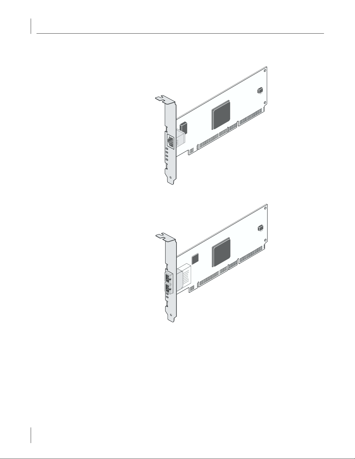
This manual covers two types of Gigabit Server NICs: server Ethernet NIC (3C996B-T):
and server fiber NIC (3C996-SX):
10
The procedure for installing a NIC in a system is identical for both NICs. Connecting the
network cables is different for Ethernet and fiber NICs (see “Connecting the Network
Cables” on page 12”).
Installing the NIC
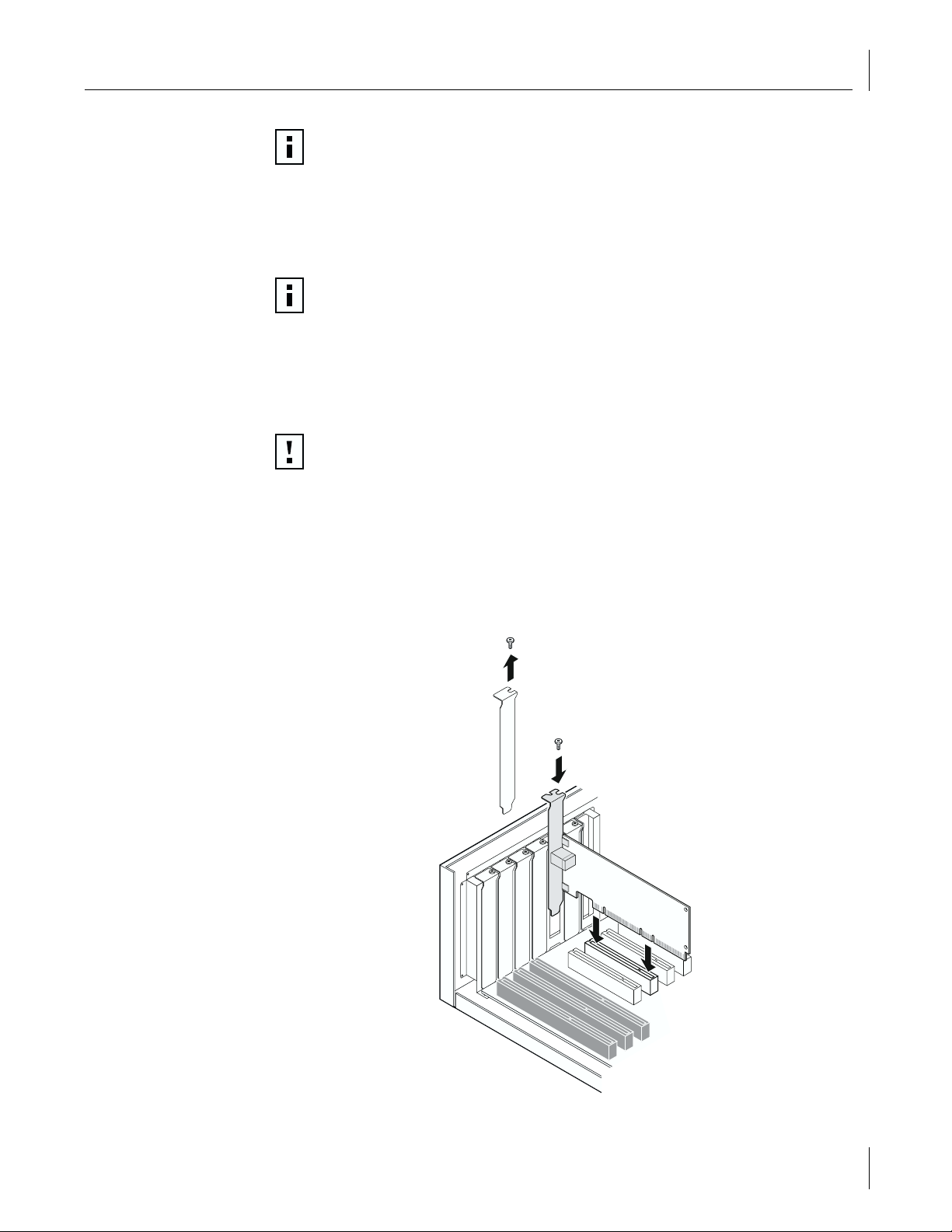
Review the precautions and pre-installation instructions. Before installing the NIC,
1
ensure the system power is off, the system is unplugged from the power outlet, and
that proper electrical grounding procedures have been followed. Refer to the
following figure to complete the remaining steps.
Remove the system cover, and select any empty PCI slot. If you do not know how to
2
identify a PCI slot, refer to your system documentation.
Page 19
Installing and Connecting the NIC
NOTE:
For optimal performance, select a PCI-X slot. For second best
performance, select a 64-bit PCI slot.
Remove the blank cover plate from the slot that you selected (see item 1 in the
3
figure, below).
Holding the PCI card by the edges, align the NIC’s connector edge with the PCI
4
connector dock.
NOTE:
The connector dock in a 32-bit PCI slot is shorter than in a 64-bit PCI slot.
Although the NIC is designed to fit in either slot type, when installed in a 32-bit
PCI slot, part of the NIC’s connector edge will remain undocked. This is perfectly
normal.
Applying even pressure at both corners of the card, push the NIC until it is firmly
5
seated in the PCI slot. When properly seated, the NIC’s port connectors will be aligned
with the slot opening, and its faceplate will be flush against the system chassis.
CAUTION:
Do not use excessive force when seating the card, as this may damage
the system or the NIC. If the card resists seating, remove it from the system,
realign it, and try again.
Secure the NIC with the screw (see item 2 in the figure, below).
6
Replace the system cover and disconnect any personal anti-static devices.
7
Turn the system power on.
8
After the system returns to normal operation, the NIC hardware is fully installed. The next
step is to connect the network cables.
1
2
11
Page 20

2 Installing and Connecting the NIC
Connecting the Network Cables
Choose your type of NIC (Ethernet or fiber) and follow the procedure.
Ethernet NICs
Gigabit Ethernet NICs have one RJ-45 connector for attaching the system to an Ethernet
copper-wire segment. When automatic link negotiation is disabled, the port can be
configured for 10 Mbps or 100 Mbps signaling and either half-duplex or full-duplex
operation. To configure the port for 1000 Mbps, both link partners must be configured for
autonegotiation.
Follow this procedure for connecting a network cable to the Gigabit Ethernet NIC:
Prepare an appropriate cable. The following table lists the cable characteristics for
1
connecting to 10/100/1000BASE-T ports:
Port Type Connector Media Maximum Distance
10BASE-T RJ-45 CAT 3, 4, or 5 UTP 100 meters (325 feet)
100BASE-T RJ-45 CAT 5 UTP (two pair) 100 meters (325 feet)
1000BASE-T RJ-45 CAT5 UTP (four pair) 100 meters (325 feet)
NOTE:
1000BASE-T signaling requires four twisted pairs of Category 5 balanced
cabling, as specified in ISO/IEC 11801:1995 and EIA/TIA-568-A (1995) and tested
using procedures defined in TIA/EIA TSB95.
Connect one end of the cable to the Gigabit Ethernet NIC.
2
Connect the other end of the cable to an RJ-45 Ethernet network port.
3
For driver installation and configuration instructions, refer to the software configuration
for that specific driver.
After the NIC hardware and its driver software have been properly installed on your
system, the LEDs indicate the following NIC states:
LED State Description
1000 On Good Gigabit Ethernet link.
Off No 1000 Mbps link; possible link at different speed, possible bad
100 On Good 100 Mbps Fast Ethernet link.
Off No 100 Mbps link; possible link at different speed, possible bad cable,
10 On Good 10 Mbps Fast Ethernet link.
Off No 10 Mbps link; possible link at different speed, possible bad cable,
ACT Blinking Brief bursts of data detected on the port.
On Streams of data detected on the port.
Off No data detected on the port.
cable, bad connector, or configuration mismatch.
bad connector, or configuration mismatch.
bad connector, or configuration mismatch.
12
Page 21

Installing and Using the 3Com Connection Assistant
Fiber NIC
If you have not already done so, remove the optical dust cap from the NIC port.
1
Connect the NIC to the network using 62.5/125 µm or 50/125 µm mulitmode fiber-
2
optic cable with SC duplex connectors.
Installing and Using the 3Com Connection Assistant
The 3Com Connection Assistant is an optional Web-based software component that
allows users access to a variety of interactive technical support services.
These services can help you:
Fix NIC installation problems.
■
Fix network connection problems.
■
Download the latest NIC drivers.
■
Access a list of frequently asked questions as well as the 3Com Knowledgebase.
■
System Requirements
To install and use the 3Com Connection Assistant requires:
Windows XP, Windows 2000, or Windows NT 4.0.
■
Internet Explorer version 4.0 or later or Netscape Navigator version 4.06 or later.
■
Microsoft Java Virtual Machine (JVM)
■
See your PC documentation if you are unsure whether your PC is a Microsoft Java
Virtual Machine (JVM).
Installation
Insert the
1
3Com Installation CD
The Welcome screen appears. If not, double-click on
click on the CD-ROM drive icon to invoke the Welcome screen.
Click
2
3
4
NIC Software
Click
3Com Connection Assistant
Follow the prompts on the screen.
.
A 3Com Connection Assistant icon appears on your Windows desktop. Double-click
the icon to start the program.
For help on using the 3Com Connection Assistant, see the online help included with
the software.
in the CD-ROM drive.
.
My Computer
, and then double-
13
Page 22

Page 23

Windows XP Driver Setup
3
Installing the Driver Software
Before you begin software installation:
Make sure that all software installation requirements are met. See “System
■
Requirements” on page 7.
Install the hardware. For instructions, see “Installing and Connecting the NIC” on
■
page 7.
NOTE:
upgraded to the latest version with the latest service pack applied.
NOTE:
works correctly.
Before beginning this procedure, verify that Windows XP has been
Make sure the correct BIOS and firmware are installed to ensure the system
Windows XP 32-bit
Use the following procedure to install the driver for the first time in a system running
Windows XP 32-bit version.
Start Windows and log in. You must have Network Administrator privileges to install
1
the driver software
Insert the
2
The main menu appears. Select
3
From the list on the left, select
4
Click
5
Click
6
The Please Wait screen appears. After the installation is complete, and Update dialog
7
box appears. Click OK.
The Choose Operating System screen appears. Click
8
Follow the steps in the Completing NIC Installation with Windows XP screen. After
9
you are through, click
3Com Installation CD
Install NIC Drivers
Install Win XP 32 NIC Drivers
.
Done
in the CD-ROM drive.
NIC Software
NIC Drivers
.
. The drivers are installed.
.
.
Windows XP
.
15
Page 24

3 Windows XP Driver Setup
Windows XP 64-bit
Use the following procedure to install the driver for the first time in a computer running
Windows XP 64-bit version.
Start Windows and log in. You must have Network Administrator privileges to install
1
the driver software
Insert the
2
The main menu appears. Select
3
From the list on the left, select
4
Click
5
Click
6
The Please Wait screen appears. After the installation is complete, and Update dialog
7
3Com Installation CD
Install NIC Drivers
.
Install Win XP 64 NIC Drivers
in the CD-ROM drive.
NIC Software
NIC Drivers
.
.
.
box appears. Click OK.
The Choose Operating System screen appears. Click
8
Follow the steps in the Completing NIC Installation with Windows XP screen. After
9
you are through, click
. The drivers are installed
Done
Windows XP
.
Driver Installation Without Master Navigator
If you cannot use the 3Com Master Navigator on your system, use the following
procedure to install the updated drivers.
Start Windows XP. The driver will be automatically installed.
1
Insert the
2
click
Select
3
In the Network Connections window, right-click on the LAN or High-Speed Internet
4
3Com Installation CD
.
Exit
Start/Control Panel/Network Connections
Connection icon corresponding to the NIC and select
Click
5
6
7
8
9
.
10
11
12
Configure
Click
Update Driver
Choose
Select
Click
Click
Install from a list or specific location (Advanced)
Don’t search, I will choose the driver
Have Disk
Browse
Select the NIC and click
Click
Finish.
, then select
.
.
and select the CD-ROM drive, then select OK.
The driver is installed.
in the CD-ROM drive. If the main menu appears,
.
.
Driver
Properties
.
and click
and click
. The driver will be copied to the hard disk.
Next
Next
.
Next
.
16
Page 25

Verifying Successful Installation
Right-click
1
Check connections in the LAN or High-Speed Internet window.
2
My Network Places
Modifying Configuration Parameters
Although the default values should be appropriate in most cases, you may change any
of the available options to meet the requirements of your specific system. After the NIC
driver software has been installed, use this procedure to verify or change the following
NIC properties:
802.1p QOS
■
Checksum Offload
■
Flow Control
■
Jumbo MTU
■
Speed and Duplex
■
Wake Up Capabilities
■
On the Desktop, right-click the
1
pop-up menu. The System Properties window displays.
Click the
2
window displays.
Hardware
tab and then click
and select
My Computer
Device Manager
Verifying Successful Installation
Properties
from the menu.
icon and select
. The Device Manager
Properties
from the
Scroll down the list of hardware devices to Network Adapters. Click the plus sign (+)
3
to the left of the icon to display the list of NICs currently configured.
Double-click the Gigabit Ethernet NIC you want to configure. The Gigabit Ethernet
4
Properties window displays, showing the General tab.
5
Select
Advanced
. A window showing the list of configurable properties (and default
values) for the NIC displays.
Change the operating parameters as desired. To change NIC operating parameters
6
listed under the Advanced tab, click the options listed under Properties and then use
the pull-down window under Value to change the default or assigned value.
NOTE:
When link negotiation is enabled, the user-configured link speed,
flow control, and duplex settings are ignored in favor of automatically
determined settings.
17
Page 26

3 Windows XP Driver Setup
The following options are available:
802.1p QOS
■
Checksum Offload
■
Flow Control
■
Jumbo MTU
■
Speed and Duplex
■
Wake Up Capabilities
■
– Disable (default)
–Enable
–None
– Rx TCP/IP Checksum
– Tx TCP/IP Checksum
– Tx/Rx TCP/IP Checksum
–Auto
– Disable (default)
–Rx PAUSE
– Rx/Tx PAUSE
–Tx PAUSE
– 1500 (default)
– 2000
– 2500
– 3000
– 3500
– 4000
– 4500
– 5000
– 5500
– 6000
– 6500
– 7000
– 7500
– 8000
– 8500
– 9000
–10 Mb Full
–10 Mb Half
– 100 Mb Full
– 100 Mb Half
– Auto (default)
– Both (default)
– Magic Packet
–None
– Wake Up Frame
18
Page 27

Removing the Driver Software
When all desired configuration is complete, click OK to accept the settings.
7
Reloading your driver is recommended. To do so, right-click
8
Right-click the NIC and select
9
Right-click the NIC and select
10
Verify that the NIC port LEDs operate as described in the table in “Installing and
11
Connecting the NIC” on page 7.
Removing the Driver Software
Windows XP automatically detects the installation of new hardware. However, Windows
XP does not automatically detect removal of driver software. You must first uninstall the
NIC driver before removing the NIC.
NOTE:
removing the driver software. See “Uninstalling Advanced Server Features” on
page 20 for details.
To remove the NIC driver and associated software, use the following procedure:
Start Windows XP system and log in. You must have Network Administrator privileges
1
to uninstall the driver software.
Select
2
The Control Panel window appears. Double-click
3
Double-click
4
The Computer Management window appears. In the left-hand pane of the window,
5
click on the “+” sign next to System Tools, and then click on
Click
6
Select
7
When the Confirm Device Removal window appears, click OK.
8
The driver and associated software are removed from your system.
If Advanced Server Features are installed, they must be uninstalled before
, then
Start
Network adapters
Uninstall
Disable
Enable
Control Panel
Computer Management
, then right-click on the 3Com NIC.
.
.
My Network Places
. You have unloaded the driver.
. You have reloaded the driver.
Administrative Tools.
.
Device Manager
.
.
NOTE:
different slot.
You must uninstall the driver before removing the NIC and moving it to a
Installing Advanced Server Features
NOTE:
I64 Server Edition.
Start Windows XP I64 Server Edition and log in. You must have Network
1
Administrator privileges to uninstall the driver software.
Insert the enclosed
2
Select
3
Right-click CD-ROM drive, and select
4
Double-click
5
Double-click
6
Advanced Server Features will only install on systems running Windows XP
3Com Installation CD
Start/My Computer
WinXP64
BcmServ
.
directory on the
directory.
into the CD-ROM drive.
Explore
. Do not select Autoplay.
3Com Installation CD
.
19
Page 28

3 Windows XP Driver Setup
Double-click
7
baspi64i.exe
This will install the Advanced Server Features software and display a window.
From this menu, you can create a team. See “Creating a Team and Assigning NICs”
on page 21, or click OK to complete installation.
Uninstalling Advanced Server Features
Start Windows XP I64 Server Edition and log in. You must have Network
1
Administrator privileges to uninstall the driver software.
Select
2
3
4
5
6
Start/Control Panel/Network Connections
Right-click any NIC and select
Click
Broadcom Advanced Server Features program driver
A Warning screen appears. Click
At the prompt, click
to restart.
Yes
Configuring Advanced Server Features
The Advanced Server Features provides load balancing, failover, and VLAN configuration
by creating teams (virtual NICs) that consist of multiple NICs.
Configuring Teaming
to install Advanced Server Features.
.
Properties
.
, and then click
to continue.
Ye s
Uninstall.
NOTE:
All teaming configurations can be optionally performed using the 3Com
Management Programs. Refer to “3Com Management Programs” on page 85 for
additional information.
Any available NIC can be configured as part of a team. Teaming is a method of grouping
multiple NICs to a virtual NIC (bundling multiple NICs to look like a single NIC). The benefit
of this approach is
load balancing
.
By selecting each of the available NICs, move each of them over to the Load Balance
Members column. This “team” now appears as one NIC. Each member in the Load
Balance Member list shares the traffic burden of all its members.
The Standby Member field is used to permit the selection of one team member to handle
traffic, if all other members in the Load Balance Member list fail (failover). The selected
Standby Member will not handle any traffic unless all Load Balance Members fail. When
one load balance member (or more) is restored (fail-back), traffic will then be resumed by
the restored team member(s).
Teaming configuration is optional. Before configuring Teaming, see the “NIC Teaming” in
Key Protocols and Interfaces.
Configuring Teaming consists of the following tasks:
Accessing the Advanced Server Features Driver Properties interface
■
Creating teams
■
Adding NICs to the teams
■
Assigning IP addresses to the teams
■
Each of these tasks is described below, along with procedures describing how to delete
NICs from a failover team and how to delete a team.
20
Page 29

Configuring Advanced Server Features
Accessing the Advanced Server Features Driver Interface
Use this procedure to access the NIC properties for teaming configuration:
Click the
1
Select
2
Network and Dial-up Connections
Broadcom Advanced Server Program Driver
menu, and then select
Start
Settings/Control Panel
, right-click
3Com Virtual NIC
.
.
, and then select
The Advanced Server Features window appears.
Interface components of the Advanced Server Features driver properties window are
described below:
Select or enter a team name.
■
This entry field is used to select or enter a team name.
Unassigned NICs
■
This list displays all of the NICs that are available to be added to a team. Because each
NIC can be added to only one team, the NIC is removed from this list after it has been
assigned to a team.
Tea m Ty p e
■
Load Balance and Failover: Load balancing
FEC/GEC: Also known as general trunking. No standby NIC is allowed when this
option is selected.
Team members
■
This list displays all NICs that belong to a selected team.
Standby NICs
■
This list displays the standby NIC selected for failover for a selected team.
VLAN List
■
This list displays all the VLANs that have been created for the selected team.
Creating a Team and Assigning NICs
A failover team comprises at least one primary NIC (a standby NIC is optional). Each NIC
can belong to only one team. To configure a new failover team, access the Advanced
Server Features Driver Properties window and perform the following steps:
Enter a team name in the “Select or enter a team name” entry field.
1
2
Click
NOTE:
Create Team
All other NICs added to the team are reconfigured automatically to
.
match the team configuration. When the basic configuration properties of a team
are changed, this changes the configuration of all NICs in the team. However,
when a NIC is removed from any failover teams, it will operate according to
the parameters set for it before becoming a member of a failover team.
Add a NIC to the team.
3
In the Unassigned NICs list, select the NIC(s) that you want to add to the team
■
created in the previous step. Move the selected NICs to the Team Members list box
using the double arrows.
When you have finished configuring failover teams, click OK to accept the changes.
■
NOTE:
At least one NIC must be displayed in the Team Members list box.
21
Page 30

3 Windows XP Driver Setup
If a team has no NICs assigned, you will be prompted to add a NIC or delete the team.
4
Click OK. When team has been correctly configured, one Virtual Team NIC driver will
be created for each configured team and will appear along with the other NICs in the
Local Area Connection Properties window. Click OK.
Configure the team IP address if necessary. Configure the IP address and any other
5
necessary TCP/IP configuration for the team. Click OK when finished. If you are
unsure as to how to configure the TCP/IP properties, consult your Microsoft
documentation.
Removing a NIC from a Team
To remove an NIC from its assigned team, select the NIC in the Team Members list and
1
then click the double left arrow. Click OK.
In the Local Area Connection Properties window, click OK.
2
The NIC will be removed from the team list and will reappear in the Unassigned
NICs list.
Deleting a Team
To delete a configured failover team and release its assigned NICs, select any NIC in
1
the team list, and then click
In the Local Area Connection Properties window click OK.
2
The team and all its assigned NICs will be removed from the team list. The released
NICs will reappear in the Unassigned NICs list.
Delete Team
. Click OK.
NOTE:
NICs that are part of a team inherit all the basic configuration properties
of the team, including VLANs associated with the team. If you delete a team, any
VLANs configured for that team will also be deleted.
Configuring VLANs
VLAN Configuration is optional. Before configuring VLANs, see “VLANs Overview” on
page 102.
NOTE:
VLANs; however, VLANs cannot be configured with foreign NICs.
When configuring VLANs for team NICs, note that any NIC or LOM that is a
member of a team inherits the configuration of the primary NIC. When a NIC or
LOM is removed from the team, however, its original configuration parameters
are used.
By default, Ethernet NICs are configured with VLAN support disabled. Up to 64 VLANs
can be defined for each team on your server. Configuring VLANs consists of the
following tasks:
Accessing the VLAN configuration interface.
■
Adding VLAN(s) to the team(s). This includes assigning a unique identifier and name
■
to each new VLAN.
Each of these tasks is described below, along with procedures describing how to delete
VLANs or modify the properties of a configured VLAN.
NICs that are members of a team can also be configured to support
22
Page 31

Configuring Advanced Server Features
Accessing the Adapter VLAN Configuration Interface
Use this procedure to access the NIC properties for VLAN Configuration:
Click the
1
Double-click the Gigabit Ethernet NIC icon
2
menu, and then select
Start
Settings, Control Panel
.
.
The Advanced Server Features configuration window is displayed. If you do not see
the Gigabit Ethernet NIC icon, you must install the 3Com Management Programs.
For more information, see “3Com Management Programs” on page 85.
The Advanced Server Features configuration window lists the installed NICs and the
VLANs configured for each team. Each VLAN is identified with a unique identifier number
and name that will appear only in this window. Interface components of the VLAN
Configuration window are described in detail below:
VLAN List
■
This list displays all VLANs that have been configured.
Control Buttons
■
There are two control buttons: Create VLAN and Delete VLAN. These buttons are used
for creating and deleting VLANs.
Adding a VLAN
You can define up to 64 VLANs per team. To configure a new VLAN, follow these steps:
From the Advanced Server Features window, select the team to which you want to
1
add a VLAN.
Enter a VLAN Name and VLAN ID, and then click
2
When you have finished adding VLANs to this team, click OK.
3
In the Local Area Connection Properties window, click OK.
4
Create VLAN
.
A new virtual NIC is created for each VLAN.
NOTE:
To maintain optimal NIC performance, your system should have 64 MB of
system memory for each eight VLANs.
When adding VLANs to a single NIC, a one-NIC team must be created.
Deleting a VLAN
To delete a configured VLAN, follow these steps:
From the Advanced Server Features window, select the team from which you want to
1
delete the VLAN, and then click
Delete VLAN
. The selected VLAN will be deleted from
the VLAN list window.
When you have finished deleting VLANs, click OK to accept the changes.
2
Click OK at the Local Area Connection Properties window.
3
Advanced Server Control Suite
If you have installed the Broadcom Advanced Server Control Suite, all Load Balancing and
VLAN configuration is done from the Advanced Server Control Suite window. You can
access the Advanced Server Control Suite by installing 3Com Management Programs.
See “3Com Management Programs” on page 85 from more details.
23
Page 32

Page 33

Windows 2000 Driver Setup
4
Installing the Driver Software
Before you begin software installation:
Make sure that all software installation requirements are met. See “System
■
Requirements” on page 7.
Install the hardware. For instructions, see “Installing and Connecting the NIC” on
■
page 7.
NOTE:
upgraded to the latest version with the latest service pack applied.
NOTE:
works correctly.
Use the following procedure to install the driver for the first time in a system running
Windows 2000.
Start Windows 2000 and log in. You must have Network Administrator privileges to
1
install the driver software.
The Windows 2000 Found New Hardware wizard detects the new NICs and begins
the driver installation.
Insert the
2
From the main menu, select
3
From the list on the left, click
4
Click
5
Click
6
The Please Wait screen appears. After the installation is completed, an Update dialog
7
box appears. Click OK.
The Choose Operating System screen appears. Click
8
Before beginning this procedure, verify that Windows 2000 has been
Make sure the correct BIOS and firmware are installed to ensure the system
3Com Installation CD
Install NIC Drivers
Install Win 2000 NIC Drivers
.
in the CD-ROM drive.
NIC Software
NIC Drivers
.
.
.
Windows 2000
.
25
Page 34

4 Windows 2000 Driver Setup
Follow the steps in the Completing NIC installation with Windows 2000 screen.
9
Click
.
Done
.
Click
10
Make sure the
11
In the Found New Hardware Wizard screen, click
12
The Install Hardware Device Drivers window appears. Click
13
for my device, and then click
The Locate Driver Files screen appears. Select the CD-ROM drives checkbox, and then
14
click
The Driver Files Search Results screen appears. Verify that the correct path to the
15
driver software is shown (c:\winnt\inf\oem0.inf), and then click
Exit
Next
.
3Com Installation CD
.
is still in the CD-ROM drive.
.
Next
Next
.
Search for
Next
a suitable driver
. If you acquired
the NIC software on a floppy disk or from the 3Com Web site, click where the NIC
driver files reside on your system.
The Completing the Found New Hardware Wizard screen appears. Click
16
Finish
After installation of the driver software is complete, you are ready to configure
NIC properties.
NOTE:
After installing the drivers, it is recommended that you install the 3Com
Management Programs to make full use of all management features. For more
information, see “3Com Management Programs” on page 85.
.
26
Page 35

Verifying Successful Installation
Right-click
1
Check connections in the Network and Dial-up Connections window.
2
My Network Places
Modifying Configuration Parameters
Although the default values should be appropriate in most cases, you may change any
of the available options to meet the requirements of your specific system. After the NIC
driver software has been installed, use this procedure to verify or change the following
NIC properties:
802.1p QOS
■
Checksum Offload
■
Flow Control
■
Jumbo MTU
■
Speed and Duplex
■
Wake Up Capabilities
■
On the Desktop, right-click the
1
pop-up menu. The System Properties window displays.
Click the
2
window displays.
Hardware
tab and then click
and select
My Computer
Device Manager
Verifying Successful Installation
Properties
from the menu.
icon and select
. The Device Manager
Properties
from the
Scroll down the list of hardware devices to Network Adapters. Click the plus sign (+)
3
to the left of the icon to display the list of NICs currently configured.
Double-click the Gigabit Ethernet NIC you want to configure. The Gigabit Ethernet
4
Properties window displays, showing the General tab.
Click the
5
Advanced
tab. A window showing the list of configurable properties (and
default values) for the NIC displays.
Change the operating parameters as desired. To change NIC operating parameters
6
listed under the Advanced tab, click the options listed under Properties and then use
the pull-down window under Value to change the default or assigned value.
NOTE:
When link negotiation is enabled, the user-configured link speed,
flow control, and duplex settings are ignored in favor of automatically
determined settings.
27
Page 36

4 Windows 2000 Driver Setup
The following options are available:
802.1p QOS
■
– Disable (default)
–Enable
Checksum Offload
■
–None
– Rx TCP/IP Checksum
– Tx TCP/IP Checksum
– Tx/Rx TCP/IP Checksum
Flow Control
■
–Auto
– Disable (default)
–Rx PAUSE
– Rx/Tx PAUSE
–Tx PAUSE
Jumbo MTU
■
– 1500 (default)
– 2000
– 2500
– 3000
– 3500
– 4000
– 4500
– 5000
– 5500
– 6000
– 6500
– 7000
– 7500
– 8000
– 8500
– 9000
Speed and Duplex
■
–10 Mb Full
–10 Mb Half
– 100 Mb Full
– 100 Mb Half
– Auto (default)
Wake Up Capabilities
■
– Both (default)
– Magic Packet
–None
– Wake Up Frame
28
Page 37

Removing the Driver Software
When all desired configuration is complete, click OK to accept the settings.
7
Reloading your driver is recommended. To do so, right-click
8
Right-click the NIC and select
9
Right-click the NIC and select
10
Verify that the NIC port LEDs operate as described in the table in “Installing and
11
Connecting the NIC” on page 7.
Removing the Driver Software
Windows 2000 automatically detects the installation of new hardware. However,
Windows 2000 does not automatically detect removal of driver software. You must
first uninstall the NIC driver before removing the NIC.
NOTE:
removing the driver software. See “Uninstalling Advanced Server Features” on
page 30 for details.
To remove the NIC, do the following:
Start Windows 2000 system and log in. You must have Network Administrator
1
privileges to uninstall the driver software.
Open the Windows Start menu and select
2
The Control Panel window appears. Double-click
3
The Add/Remove Hardware Wizard window appears. Click
4
The Choose a Hardware Task window appears. Click
5
(recommended), and then click
to prepare your computer for unplugging a device.
The Choose a Removal Task window appears. Click
6
and then click
its driver.
If Advanced Server Features are installed, they must be uninstalled before
My Network Places
Disable
Enable
. Choose this option to permanently uninstall a device and
Next
. You have unloaded the driver.
. You have reloaded the driver.
Next
:
.
Setting, Control Panel
Add/remove Hardware Wizard
Uninstall/Unplug a device
. Choose this option to uninstall a device or
Next
Uninstall a device
.
.
(recommended),
The Installed Devices on Your Computer screen appears. Click the network adapter
7
card you want to uninstall (3Com 3C996 10/100/1000 Server NIC), and then
click
In the Uninstalled Devices window, click Y
8
click
The Completing the Add/Remove Hardware Wizard window appears. Click
9
Now you can shut down your system and you can physically remove the NIC from
the server.
NOTE:
different slot.
.
Next
es, I want to uninstall this device
.
Next
You must uninstall the driver before removing the NIC and moving it to a
, and then
Finish
.
29
Page 38

4 Windows 2000 Driver Setup
Installing Advanced Server Features
NOTE:
2000 Server operating system (Server, Advanced Server, or Datacenter Server).
Start Windows 2000 Server and log in. You must have Network Administrator
1
privileges to install the driver software.
Insert the
2
If the main menu appears, click
3
Double-click
4
Right-click CD-ROM drive, and select
5
Double-click
6
Double-click
7
Double-click
8
This will install the Advanced Server Features software and display a window.
From this menu, you can create a team. See “Creating a Team and Assigning NICs”
on page 31, or click OK to complete installation.
Advanced Server Features will only install in a system running a Windows
3Com Installation CD
My Computer
Windows 2000
BcmServ
Baspinst.exe
directory.
Uninstalling Advanced Server Features
Start Windows 2000 system and log in. You must have Network Administrator
1
privileges to uninstall the driver software.
Select
2
3
4
5
6
Start/Settings/Control Panel/Network and Dial-up Connections
Right-click any NIC and select
Click
Broadcom Advanced Server Features program driver
A Warning screen appears. Click
At the prompt, click
to restart.
Yes
into the CD-ROM drive.
.
Exit
icon.
Explore
directory on the
to install Advanced Server Features.
Properties
to continue.
Ye s
. Do not select Autoplay.
3Com Installation CD
.
, and then click
.
.
Uninstall.
Configuring Advanced Server Features
The Advanced Server Features provides load balancing, failover, and VLAN configuration
by creating teams (virtual NICs) that consist of multiple NICs.
Configuring Teaming
NOTE:
Management Programs. Refer to “3Com Management Programs” on page 85 for
additional information.
Any available NIC can be configured as part of a team. Teaming is a method of grouping
multiple NICs to a virtual NIC (bundling multiple NICs to look like a single NIC). The benefit
of this approach is
By selecting each of the available NICs, move each of them over to the Load Balance
Members column. This “team” now appears as one NIC. Each member in the Load
Balance Member list shares the traffic burden of all its members.
30
All teaming configurations can be optionally performed using the 3Com
load balancing
.
Page 39

Configuring Advanced Server Features
The Standby Member field is used to permit the selection of one team member to handle
traffic, if all other members in the Load Balance Member list fail (failover). The selected
Standby Member will not handle any traffic unless all Load Balance Members fail. When
one load balance member (or more) is restored (fail-back), traffic will then be resumed by
the restored team member(s).
Teaming configuration is optional. Before configuring Teaming, see the “NIC Teaming” in
Key Protocols and Interfaces.
Configuring Teaming consists of the following tasks:
Accessing the Advanced Server Features Driver Properties interface
■
Creating teams
■
Adding NICs to the teams
■
Assigning IP addresses to the teams
■
Each of these tasks is described below, along with procedures describing how to delete
NICs from a failover team and how to delete a team.
Accessing the Advanced Server Features Driver Interface
Use this procedure to access the NIC properties for teaming configuration:
Click the
1
Select
2
Network and Dial-up Connections
Broadcom Advanced Server Program Driver
menu, and then select
Start
Settings/Control Panel
, right-click
3Com Virtual NIC
.
.
, and then select
The Advanced Server Features window appears.
Interface components of the Advanced Server Features driver properties window are
described below:
Select or enter a team name.
■
This entry field is used to select or enter a team name.
Unassigned NICs
■
This list displays all of the Ethernet NICs that are available to be added to a team.
Because each NIC can be added to only one team, the NIC is removed from this list
after it has been assigned to a team.
Tea m Ty p e
■
Load Balance and Failover: Load balancing
FEC/GEC: Also known as general trunking. No standby NIC is allowed when this
option is selected.
Team members
■
This list displays all NICs that belong to a selected team.
Standby NICs
■
This list displays the standby NIC selected for failover for a selected team.
VLAN List
■
This list displays all the VLANs that have been created for the selected team.
Creating a Team and Assigning NICs
A failover team comprises at least one primary NIC (a standby NIC is optional). Each NIC
can belong to only one team. To configure a new failover team, access the Advanced
Server Features Driver Properties window and perform the following steps:
Enter a team name in the “Select or enter a team name” entry field.
1
2
Click
Create Team
.
31
Page 40

4 Windows 2000 Driver Setup
NOTE:
All other NICs added to the team are reconfigured automatically to match
the team configuration. When the basic configuration properties of a team are
changed, this changes the configuration of all NICs in the team. However, when
a NIC is removed from any failover teams, it will operate according to the
parameters set for it before becoming a member of a failover team.
Add a NIC to the team.
3
In the Unassigned NICs list, select the NIC(s) that you want to add to the team
■
created in the previous step. Move the selected NICs to the Team Members list box
using the double arrows.
When you have finished configuring failover teams, click OK to accept the changes.
■
NOTE:
If a team has no NICs assigned, you will be prompted to add a NIC or delete the team.
4
At least one NIC must be displayed in the Team Members list box.
Click OK. When team has been correctly configured, one Virtual Team NIC driver will
be created for each configured team and will appear along with the other NICs in the
Local Area Connection Properties window. Click OK.
Configure the team IP address if necessary. Configure the IP address and any other
5
necessary TCP/IP configuration for the team. Click OK when finished. If you are
unsure as to how to configure the TCP/IP properties, consult your Microsoft
documentation.
Removing a NIC from a Team
To remove an NIC from its assigned team, select the NIC in the Team Members list and
1
then click the double left arrow. Click OK.
In the Local Area Connection Properties window, click OK.
2
The NIC will be removed from the team list and will reappear in the Unassigned
NICs list.
Deleting a Team
To delete a configured failover team and release its assigned NICs, select any NIC in
1
the team list, and then click
In the Local Area Connection Properties window click OK.
2
Delete Team
. Click OK.
The team and all its assigned NICs will be removed from the team list. The released
NICs will reappear in the Unassigned NICs list.
NOTE:
NICs that are part of a team inherit all the basic configuration properties of
the team, including VLANs associated with the team. If you delete a team, any
VLANs configured for that team will also be deleted.
Configuring VLANs
VLAN Configuration is optional. Before configuring VLANs, see “VLANs Overview” on
page 102.
32
Page 41

Configuring Advanced Server Features
NOTE:
NICs that are members of a team can also be configured to support
VLANs; however, VLANs cannot be configured with foreign NICs.
When configuring VLANs for team NICs, note that any NIC or LOM that is a
member of a team inherits the configuration of the primary NIC. When a NIC or
LOM is removed from the team, however, its original configuration parameters
are used.
By default, Ethernet NICs are configured with VLAN support disabled. Up to 64 VLANs
can be defined for each team on your server. Configuring VLANs consists of the
following tasks:
Accessing the VLAN configuration interface.
■
Adding VLAN(s) to the team(s). This includes assigning a unique identifier and name
■
to each new VLAN.
Each of these tasks is described below, along with procedures describing how to delete
VLANs or modify the properties of a configured VLAN.
Accessing the Adapter VLAN Configuration Interface
Use this procedure to access the NIC properties for VLAN Configuration:
Click the
1
Double-click the Gigabit Ethernet NIC icon
2
menu, and then select
Start
Settings, Control Panel
.
.
The Advanced Server Features configuration window is displayed. If you do not see
the Gigabit Ethernet NIC icon, you must install the 3Com Management Programs.
For more information, see “3Com Management Programs” on page 85.
The Advanced Server Features configuration window lists the installed NICs and the
VLANs configured for each team. Each VLAN is identified with a unique identifier number
and name that will appear only in this window. Interface components of the VLAN
Configuration window are described in detail below:
VLAN List
■
This list displays all VLANs that have been configured.
Control Buttons
■
There are two control buttons: Create VLAN and Delete VLAN. These buttons are used
for creating and deleting VLANs.
Adding a VLAN
You can define up to 64 VLANs per team. To configure a new VLAN, follow these steps:
From the Advanced Server Features window, select the team to which you want to
1
add a VLAN.
Enter a VLAN Name and VLAN ID, and then click
2
When you have finished adding VLANs to this team, click OK.
3
In the Local Area Connection Properties window, click OK.
4
Create VLAN
.
A new virtual NIC is created for each VLAN.
NOTE:
To maintain optimal NIC performance, your system should have 64 MB of
system memory for each eight VLANs.
When adding VLANs to a single NIC, a one-NIC team must be created.
33
Page 42

4 Windows 2000 Driver Setup
Deleting a VLAN
To delete a configured VLAN, follow these steps:
From the Advanced Server Features window, select the team from which you want to
1
delete the VLAN, and then click
the VLAN list window.
When you have finished deleting VLANs, click OK to accept the changes.
2
Click OK at the Local Area Connection Properties window.
3
Advanced Server Control Suite
If you have installed the Broadcom Advanced Server Control Suite, all Load Balancing and
VLAN configuration is done from the Advanced Server Control Suite window. You can
access the Advanced Server Control Suite by installing 3Com Management Programs.
See “3Com Management Programs” on page 85 from more details.
Updating Mini-port (Core) Drivers
If you plan to update your network drivers and you are using an Advanced Server Feature
team, use the following procedures.
Delete VLAN
. The selected VLAN will be deleted from
CAUTION:
connectivity before and after a system reboot.
Right-click
1
Open the properties for the virtual NIC.
2
Open the Internet Protocol (TCP/IP) properties.
3
Write down the IP address information, and then click
4
Right-click the local area connection you wish to update, and then select
5
Click
6
7
8
9
10
11
12
13
14
Configure
Click the
Click
Display a list of the known drivers for the device so that I can choose a specific
Click
driver.
Click
Have Disk
Type the path to the updated driver, and then click OK.
Example:
Select the Gigabit Ethernet NIC, and then click
Click
Next
Repeat steps 5 through 12 for each NIC you want to update.
In the last local area connection, open the Advanced Server Features driver properties.
Failure to use the following procedure might result in loss of network
My Network Places
.
tab, and then click
Driver
.
Next
.
E:\
, and then click OK.
and choose
Update Driver
Properties
. Click
Next
.
.
Cancel
Next
.
.
Properties
.
34
Click
15
Type the filename, and then click OK to save the team information to be used during
16
a restore.
Select the team, and then click
17
Click OK to make the changes.
18
Open the properties on a local area connection.
19
Save
.
Delete Team
. Click OK.
Page 43

Updating Mini-port (Core) Drivers
Open the Advanced Server Features driver properties.
20
Click
21
22
23
24
25
Restore.
Type the filename you used during the save. Click OK.
Click OK twice to make the changes.
The virtual NIC appears in the Network and Dialup Connections window. Open the
properties for the virtual NIC.
Reset the IP address for the virtual NIC, and then click OK twice to bring up the team.
35
Page 44

Page 45

Windows NT Driver Setup
5
Installing the Driver Software
Before you begin software installation:
Make sure that all installation requirements are met. See “System Requirements” on
■
page 7.
Install the hardware. See “Installing and Connecting the NIC” on page 7.
■
NOTE:
system works correctly.
NOTE:
the latest service pack). If you attempt to install the driver on a new Windows NT
system without Service Pack 5 (or the latest service pack), the installation may not
be successful. (3Com has tested and supports only Service Pack 6a.)
Before installing a service pack, you must first install the MS Loopback Adapter
driver. For information on how to install Microsoft Loopback driver and how to
install Backup Domain Controller, see the release notes for Windows NT.
Use the following procedure to install the driver for the first time in a computer that is
running Windows NT.
Start the Windows NT system and log in. You must have Network Administrator
1
privileges to install the driver software.
Insert the
2
From the Welcome screen, click
3
Click
4
Click
5
The Gigabit Ethernet Controller screen appears. Click
6
parameters, see “Modifying Configuration Parameters” on page 38.
The TCP/IP Properties window opens. Perform any necessary TCP/IP configuration and
7
click OK when finished. For help configuring TCP/IP protocol, consult your Microsoft
Windows NT 4.0 documentation
Make sure that the correct BIOS and Firmware are installed to ensure the
Verify that your Windows NT system is upgraded with Service Pack 5 (or
3Com Installation CD
NIC Drivers
Install NIC Driver
.
.
in the CD-ROM drive.
NIC Software
.
Continue
. To change
An update window appears. Click OK.
8
The Choose Operating System screen appears. Click
9
Read the steps in the Completing NIC installation with Windows NT screen.
10
Click
Done
.
Windows NT
.
37
Page 46

5 Windows NT Driver Setup
11
Click
, and then perform the steps outlined in Completing NIC installation with
Exit
Windows NT screen.
When prompted to restart your computer, click
12
Yes
The system restarts, using the new configuration settings.
.
When the system returns to normal operation, verify that the NIC port LEDs operate
13
as described in “Installing and Connecting the NIC” on page 7.
NOTE:
After installing the drivers, it is recommended that you install the 3Com
Management Programs to make full use of all management features. For more
information, see “3Com Management Programs” on page 85.
Modifying Configuration Parameters
After the NIC driver software has been installed, you can change the configuration
options at any time. The following NIC parameters are user-configurable:
Basic properties: Flow Control, Speed and Duplex, and Jumbo MTU.
■
Optional properties: Failover Team Configuration and VLAN Configuration.
■
NICs configured as part of a failover share basic configuration properties. Changing the
configuration of one NIC in a specific team changes the properties of all the NICs in
that team.
To access the NIC properties:
Open the Control Panel and double-click the
1
When the Network window opens, select the
2
The bus and slot number of the highlighted NIC are listed in the lower part of
the window.
Network
Adapters
icon.
tab.
38
Page 47

Modifying Configuration Parameters
Select the desired NIC from the Network Adapters window and click
3
The Gigabit Ethernet Controller window opens.
The possible NIC parameter types are:
Flow Control
■
– Disable (default)
–Enable
Speed and Duplex
■
– Auto (default)
–10 Mb Half
–10 Mb Full
– 100 Mb Half
– 1000 Mb Full
Jumbo MTU
■
– 1500 (default)
– 2000
– 2500
– 3000
– 3500
– 4000
– 4500
– 5000
– 5500
– 6500
– 7000
– 7500
– 8000
– 8500
– 9000
Properties
.
When NIC parameter configuration is complete, click OK to accept the settings.
4
When prompted to restart your computer, click
5
Yes
.
The system restarts, using the new configuration settings.
When the system returns to proper operation, verify that the adapter port LEDs
6
operate as described in the table in “Installing and Connecting the NIC” on page 7.
NOTE:
If no configuration changes have been made, you can click No to close the
configuration session without restarting your system.
39
Page 48

5 Windows NT Driver Setup
Updating the Driver Software
To replace version 4.0 NIC driver software with newer versions as they become available:
Start your Windows NT system and log in. You must have Network Administrator
1
privileges to install the driver software.
Insert the
2
From the Welcome screen, select
3
Click
4
And Update screen appears. Click OK.
5
3Com Installation CD
Update NIC Driver
in the CD-ROM drive.
NIC Software
.
.
The Update NIC Drivers screen appears. Click
6
Click
7
When prompted to restart your computer, click
8
configuration settings.
Exit
.
Removing the Driver Software
You must uninstall the driver before removing a NIC or moving it to another slot in the
server. To uninstall the driver software, do the following:
Start your Windows NT system and log in. You must have Network Administrator
1
privileges to install the driver software.
Click the
2
The Control Panel screen opens. Double-click the
3
The Network window appears. Select the
4
Click the NIC you want to uninstall, and then click
5
A “Do you still wish to continue” message appears. Click
6
In the Network Adapters screen, click OK to finish uninstalling the driver.
7
When prompted to restart your computer, click
8
system, and then physically remove the network interface card from the PCI slot.
NOTE:
another slot in the server. When the driver software has been successfully
uninstalled, you can shut down the system and remove the NIC from the PCI slot.
Start
You must uninstall the driver before removing a NIC or moving it to
menu, and then select
.
Done
. The system restarts using the new
Yes
Setting, Control Panel
Network
Adapters
tab.
Remove
. Now you can shut down your
Yes
.
icon
.
Yes
.
40
Page 49

Installing Advanced Server Features
These features are only available for Windows NT Server and Enterprise Server
operating systems.
NOTE:
Microsoft Loopback Adapter before installing the Advanced Server Features. If
needed, you can reinstall the Microsoft Loopback Adapter afterwards. For more
information see “Installing the Microsoft Loopback Adapter Driver” on page 46.
Start your Windows NT system and log in. You must have Network Administrator
1
privileges to install the driver software.
If you have problems installing the Advanced Server Features, uninstall the
Installing Advanced Server Features
Insert the enclosed
2
From the Welcome screen, click
3
Advanced Server Features.
Click the
4
The Control Panel window appears. Double-click the
5
In the Network window, click the
6
Click
7
The Select Network Protocol window appears. Click
8
The Insert Disk window appears. Type
9
CD-ROM drive. Click OK.
The Select OEM Option window appears. Click OK.
10
This will install the Advanced Server Features software and display a window.
From this menu, you can create a team (see “Creating a Team and Assigning NICs” on
page 42), or click OK to complete installation.
In the Network window, click
11
When prompted to restart your computer, click
12
Advanced Server Features should be installed.
Add
Start
.
3Com Installation CD
menu, and then select
Uninstalling Advanced Server Features
Start your Windows NT system and log in. You must have Network Administrator
1
privileges to install the driver software.
Click
2
Double-click the
3
The Network window appears. Click the
4
Select Advanced Server Features, and then click
5
, and then select
Start
Network
into the CD-ROM drive.
You must exit the Master Navigator to install
Exit.
Settings, Control Panel
Protocols
Close.
Settings, Control Panel
icon.
tab.
e:\WindowsNT\BcmServ\
Protocols
.
Network
Have Disk
. After the system restarts,
Yes
.
tab.
Remove
icon.
.
where “e” is the
.
NOTE:
be deleted.
A Warning screen appears. Click
6
In the
7
When prompted to restart your computer, click
8
Advanced Server Features will be uninstalled.
Before deleting Advanced Server Features, all teams and VLANs must
to continue.
Ye s
Network
window, click
Close
.
. When the system restarts,
Yes
41
Page 50

5 Windows NT Driver Setup
Configuring Teaming
Teaming configuration is optional. Before configuring Failover Teaming, see “NIC
Teaming” on page 101.
Configuring Teaming consists of the following tasks:
Accessing the Advanced Server Features Driver Properties
■
Creating teams
■
Adding NICs to the teams
■
Assigning an IP address to the teams
■
Rebooting the system
■
Each of these tasks is described below, along with how to delete NICs from a failover
team and how to delete a team. For each procedure, you must log in as the Network
Administrator.
Accessing the Advanced Server Features Driver Interface
Open the Control Panel and double-click the
1
When the Network window opens, select the
2
Select Advanced Server Features program driver, and then click
3
The Advanced Server Features window is displayed.
Interface components of the Advanced Server Features window are described below:
Select or enter a team name.
■
(The entry field is used to select or enter a team name.)
Unassigned NICs
■
This list displays all of the Ethernet NICs that are available to be added to a team.
■
Because each adapter can be added to only one team, the NIC is removed from this
list after it has been assigned to a team.
Tea m Ty p e
■
Load Balance and Failover: Load balancing
FEC/GEC: Also known as general trunking. No standby NIC is allowed when this
option is selected.
Team members
■
This list displays all NICs that belong to a selected team.
Standby NIC
■
This list displays the standby NIC selected for failover belonging to a selected team.
VLAN List
■
This list displays all the VLANs that have been created for the selected team.
Network
Protocols
icon.
tab.
Properties
.
42
Creating a Team and Assigning NICs
A failover team comprises at least one primary NIC and one standby NIC. Each NIC can
belong to only one team. To configure a new team, access the Advanced Server Program
Driver Properties window and do the following:
Enter a team name in the “Select or enter a team name” entry field.
1
2
Click
Create Team
.
Page 51

Uninstalling Advanced Server Features
NOTE:
All other NICs added to the team are reconfigured automatically to match
the team configuration. When a basic team configuration properties are changed,
this changes the configuration of all NICs in the team. However, after an NIC has
been removed from any team, it will operate according to the parameters set for it
before becoming a member of a team.
Add a NIC to the team.
3
In the Unassigned NICs list, select the NIC(s) that you want to add to the team
■
(created in the previous step). Move the selected NIC(s) to the Team members list
box using the double arrows.
When you have finished configuring failover teams, click OK to accept the changes.
■
In the Network window, click
■
NOTE:
At least one NIC must be displayed in the Team Members list box. If a team
Close
.
has no NICs assigned, you will be prompted to add another NIC or delete
the team.
The TCP/IP Properties window appears. Configure the Team IP address. Configure the
4
IP address and any other necessary TCP/IP configuration for the team and click OK
when finished. If you are unsure as to how to configure the TCP/IP properties, consult
your Microsoft documentation.
When prompted to restart the system, click
5
. The system restarts, making
Ye s
the changes.
Removing NICs from a Team
To remove a NIC from its assigned team, select the NIC in the Team Members list and
1
click the double left arrow. Click OK.
In the Network window, click
2
When prompted to restart the system, click
3
Close
.
.
Ye s
The NIC will be removed from the team list and will reappear in the Unassigned
NICs list.
Deleting a Team
To delete a configured failover team and release its assigned NICs, select the NIC in
1
the team list, and then click
In the Network window, click
2
When prompted to restart the system, click
3
Delete Team
Close
.
. Click OK.
.
Ye s
The team and all its assigned NICs will be removed from the team list. The released
NICs will reappear in the Unassigned NICs list.
NOTE:
NICs that are part of a team inherit all the basic configuration properties of
the team, including VLANs associated with the team. If you delete a team, any
VLANs configured for that team will also be deleted.
43
Page 52

5 Windows NT Driver Setup
Configuring VLANs
VLAN configuration is optional. Before configuring VLANs, see the “VLANs Overview” on
page 102.
NOTE:
VLANs. VLANs, however, cannot be configured for an Intel stand-alone LAN
on Motherboard (LOM) or a team that includes a LOM.
When configuring VLANs for team NICs, note that any NIC or LAN-onmotherboard (LOM) that is a member of a team inherits the configuration of the
primary NIC. However, when an NIC or LOM is removed from the team, its original
configuration parameters are used.
By default, Gigabit Ethernet NICs are configured with VLAN support disabled. As many
as 64 VLANs can be defined for each Gigabit Ethernet NIC on your server. Configuring
VLANs consists of the following tasks:
Accessing the VLAN configuration interface.
■
Adding VLAN(s) to the NIC(s). This includes assigning a unique identifier and
■
(optional) name to each new VLAN.
Rebooting the system.
■
Each of these tasks is described below, along with how to delete VLANs or modify the
properties of a configured VLAN.
NICs that are members of a team can also be configured to support
Accessing the NIC VLAN Configuration Interface
Open your system Control Panel and double-click the
1
When the Network window opens, select the
2
Select the Advanced Server Features driver and click
3
Protocols
Properties
Network
tab.
icon.
. The Advanced Server
Features window is displayed, from which you can configure VLANs.
The Advanced Server Features configuration window lists the installed NICs and the
VLANs configured for each team, if any. Each VLAN is identified with a unique identifier
number and name that will appear only in this window. Interface components of the
VLAN Configuration window are described in detail below:
VLAN List
■
This list displays all VLANs that have been configured.
Control Buttons
■
There are two control buttons:
Create VLAN
, and
Delete VLAN
. These are used for
creating and deleting VLANs.
Adding a VLAN
You can define as many as 64 VLANs per team. To configure a new VLAN, do the
following:
From the Advanced Server Features window, select the team to which you want to
1
add a VLAN.
Enter a VLAN Name and VLAN ID, then click
2
When you have finished adding VLANs to this team, click OK.
3
Create VLAN
.
44
In the Network window, click
4
Close
.
Page 53

Uninstalling Advanced Server Features
The TCP/IP Properties window appears. Select the VLAN and configure TCP/IP
5
settings. Click
When finished, click OK.
. You must configure TCP/IP settings for each VLAN you created.
Apply
When prompted to restart the system, click
6
A new virtual NIC will be created for each VLAN.
NOTE:
system memory for each eight VLANs created.
To maintain optimal NIC performance, your system should have 64 MB of
Ye s
.
Deleting a VLAN
NOTE:
be deleted.
NICs that are part of a team inherit all the basic configuration properties of the team,
including VLANs associated with the team. If you delete a team, any VLANs configured for
that team will also be deleted.
To delete a configured VLAN, do the following:
From the Advanced Server Features window, select the VLAN you want to delete and
1
click
When you have finished deleting VLANs, click OK to accept the changes.
2
In the Network window, click
3
NOTE:
You must configure TCP/IP settings for the team. When finished, click OK.
When prompted to restart the system, click
4
If you delete a team, any VLANs configured for that team will also
Delete VLAN
If you delete all VLANs for a team, the TCP/IP Properties window appears.
. The selected VLAN will be deleted from the VLAN list window.
.
Close
.
Ye s
NOTE:
NIC assignments [Primary/Standby] are still present, but the IP address for the team
is deleted.
When VLANs are created and then deleted, the original team name and
Advanced Server Control Suite
If you have installed the Broadcom Advanced Server Control Suite, all Load Balancing and
VLAN configuration is done from the Advanced Server Control Suite window. You can
access the Advanced Server Control Suite by installing 3Com Management Programs.
See “3Com Management Programs” on page 85 from more details.
45
Page 54

5 Windows NT Driver Setup
Installing the Microsoft Loopback Adapter Driver
When you do a fresh installation of Windows NT 4.0, Microsoft recommends that you
install the Microsoft Loopback Adapter driver, and then verify that networking is
operating normally before installing any NICs. The Loopback Adapter driver enables
the computer to connect to local network resources that then allow alerter and
messenger services to start on a stand-alone system.
Failure to install the Loopback Adapter driver before installing a service pack can result
in a corrupted operating system. 3Com has tested and supports only Service Pack 6a.
To install the driver, do the following:
Start the Windows NT 4.0 fresh installation and proceed as usual.
1
In the Windows NT 4.0 Server Setup window, click
2
In the list, locate and select
3
In the Windows NT Server Setup window, click
4
Bind protocols (TCP/IP, NetBEUI, or IPX/SPX) to the Loopback adapter driver, and then
5
click
Continue the installation as usual.
6
Next
.
MS Loopback Adapte
Select from List
r and click OK.
.
Next
.
When prompted, click
7
Install the service pack.
8
When prompted, click
9
Install the 3Com Gigabit Ethernet NIC, its driver, and Advanced Server Features.
10
Bind protocols (TCP/IP, NetBEUI, or IPX/SPX) to the 3Com Gigabit Ethernet NIC driver.
11
When prompted, click
12
to restart the computer.
Ye s
to restart the computer.
Ye s
to restart the computer.
Ye s
Performing a Fresh Installation of Windows NT on a Backup Domain Controller
CAUTION:
domain controller security database. Before you proceed, back up your system.
A fresh installation of Windows NT on a backup domain controller requires the following:
Installation of the NIC driver
■
Network connectivity
■
Because the NIC driver installation requires that the latest Microsoft service pack first
be installed, and because there is no way to install a service pack during a Windows
NT fresh installation on a backup domain controller, you must first set up two servers
as primary domain controllers, and then demote one of them to a backup domain
controller.
If performed incorrectly, this procedure can destroy the primary
46
CAUTION:
the primary domain controller that you wish to demote to a backup domain
controller. If these items are on the primary domain controller, you must reinstall
them after you finish this procedure.
Do not use this procedure if SQL or Microsoft Exchange are on
Page 55

Performing a Fresh Installation of Windows NT on a Backup Domain Controller
CAUTION:
If performed incorrectly, this procedure can destroy the primary
domain controller security database. Use the rdisk /s command to make
emergency repair diskettes to backup the server security databases on the
two servers before attempting this procedure.
Install Windows NT 4.0 with service pack 6a on two servers set up as primary domain
1
controllers. (Follow the procedure in “Installing the MS Loopback Driver in Windows
4.0,” above.)
Connect the two servers to the same network.
2
Create two domains in the same network. Set up the server and domain names.
3
For example:
Server/Domain Name
Server one SERVER-1
Domain one DOMAIN-1
Server two SERVER-2
Domain two DOMAIN-2
Place SERVER-1 in DOMAIN-1.
4
Place SERVER-2 in DOMAIN-2.
5
Set the same administrator password on both SERVER-1 and SERVER-2.
6
Setting up SERVER 1
7
Start Server Manager on DOMAIN-1\SERVER-1. From the Start menu, select
8
Administrative Tools (Common)/Server Manager
From the Computer menu, select
9
Select
10
11
Windows NT Backup Domain Controller
In the Computer Name field, enter the domain and server name. For example:
Add to Domain
.
.
as the computer type.
DOMAIN-2\SERVER-2
12
13
Click
Click
Add
Close
.
.
Programs/
Setting up SERVER 2
Start Server Manager on DOMAIN-2\SERVER-2. From the Start menu, select
1
Administrative Tools (Common)/Server Manager
From the Computer menu, select
2
Select
3
4
Windows NT Backup Domain Controller
In the Computer Name field, enter the domain and server name. For example:
Add to Domain
DOMAIN-1\SERVER-1
5
6
Click
Click
Add
Close
.
.
.
.
as the computer type.
Programs/
47
Page 56

5 Windows NT Driver Setup
Stopping the Net Logon Service on SERVER 1
Double-click the
1
Double-click
2
In the Services dialog box, select
3
Click
4
Click
5
Close the Services dialog box.
6
Stopping the Net Logon Service on SERVER 2
Double-click the
7
Double-click
8
In the Services dialog box, select
9
Click
10
Click
11
This unlocks the security database.
Close the Services dialog box.
12
Control Panel
Services
.
Stop
to stop the net logon service. This unlocks the security database.
Yes
Services
.
Stop
to stop the net logon service
Yes
.
Control Panel
.
.
Net Logon
.
Net Logon
.
.
Renaming Domain-2/SERVER-2 to DOMAIN-1/SERVER-2
On SERVER-2, double-click the
1
Double-click
2
In the Network dialog box, click the
3
Click
4
5
6
7
8
9
10
11
12
13
14
15
Change
In the Domain Name field, replace the name DOMAIN-2 with the name DOMAIN-1
and click OK. This process takes a few moments.
Click
Yes
In the Welcome to DOMAIN-1 domain dialog box, click OK.
Close the Network dialog box.
Click No at the prompt to restart the computer.
Establishing the Backup Domain Controller
Restart SERVER-1 and log in.
Restart SERVER-2, log in, and then wait for all services to start. Do not be alarmed if
you receive a fail service message.
On SERVER-1, start Server Manager.
From the View menu, select
SERVER-1 and SERVER-2 as PRIMARY controllers.
On SERVER-2, start Server Manager.
Network
.
to the Warning prompt.
.
Control Panel
Identification
Refresh
. The Server Manager dialog box shows both
.
tab.
48
In the Server Manager dialog box, select
16
From the Computer menu, select
17
click
Ye s
.
SERVER-1
Demote to Backup Domain Controller
.
, and then
Page 57

Updating Mini-port (Core) Drivers
On SERVER-1, refresh the Server Manager dialog box. From the View menu, select
18
Refresh
SERVER-1 as BACKUP.
. The Server Manager dialog box now shows SERVER-2 as PRIMARY and
Select
19
20
21
22
23
24
25
SERVER-2
From the Computer menu, select
Click
Click OK.
Restart SERVER-1.
Restart SERVER-2.
Verify that services are starting correctly. If the backup domain controller begins to
receive 7023 or 3210 errors after you synchronize the domains, correct the situation
as follows:
a
b
c
to start synchronization.
Yes
On the primary domain controller, start Server Manager and select the backup
domain controller.
Synchronize that specific backup domain controller with the primary domain
controller.
After an event indicates that the synchronization is complete, restart the backup
domain controller.
.
Updating Mini-port (Core) Drivers
If you plan to update your network drivers and you are using an Advanced Server Feature
team, use the following procedures.
Synchronize with Primary Domain Controller
.
CAUTION:
connectivity before and after a system reboot.
Right-click
1
Select the
2
Open the TCP/IP Protocol properties.
3
Write down the IP address information for the virtual NIC, and then click
4
Click the
5
Highlight the network adapter, and then click
6
Type the path to the updated driver, and then click
7
Example:
Open the Advanced Server Features driver properties.
8
Click
9
10
11
12
13
14
Save
Type a filename to save the team information to be used during a restore, and then
click OK.
Select a team, and then click
Click
Close
After the machine restarts, right-click
Select the
Failure to use the following procedure might result in loss of network
Network Neighborhood
Protocols
Adapters
E:\
.
, and then click
Protocols
tab.
tab.
Delete Team
Yes
tab.
and choose
to restart the computer.
Network Neighborhood
Properties
Update
. Click OK to remove the team.
.
.
Continue
.
and choose
Cancel
.
Properties.
49
Page 58

5 Windows NT Driver Setup
Open the Advanced Server Features driver properties.
15
Click
16
17
18
19
20
Restore
Type the filename you used during the save, and then click OK.
Click OK again to make the changes.
Click
Close
When the machine prompts you to restart, click
.
to reset the IP address on the virtual NIC.
Yes
.
50
Page 59

Novell NetWare Driver Setup
6
Pre-Installation Requirements
The NIC must be installed in the server.
■
Install the latest support pack files. The NetWare support pack or patch file(s) needed
■
for your server operating system are indicated below:
NetWare OS
NetWare 5.1 NetWare 5.1 Support
NetWare 4.2 Support Pack 8.0 or
NOTE:
need to install the NIC driver during the OS installation procedure. Install the
NetWare 5 support pack after you have successfully installed the operating system
on the server.
To obtain the latest support pack files, go to the Novell support Web site and select the
Minimum Patch List option in the navigation bar. Scroll down the page and, using the
table above as a guide, select and download the latest support pack or patch file(s) for the
operating system running on your server.
NOTE:
with the NetWare 4.2 Support Pack. Follow the support pack instructions for
including the ODI LAN drivers during installation.
Support Pack or
Patch Files to be Installed
Pack (or latest support
pack)
later
NetWare 5.x: If you are installing NetWare 5.x for the first time, you will
NetWare 4.2: The latest ODI LAN drivers are not installed automatically
Installing Novell NetWare Server 4.2
When you install the operating system, select the custom method.
1
The latest support packs can be found at:
http://support.novell.com/misc/patlst.htm
When you’re asked if you would like to add startup commands, select
2
Enter the maximum and minimum packet receive buffers.
3
The default maximum number of receive buffers for the system is 500; the default
minimum is 128. Edit the startup.ncf file to have the following entries:
SET MAXIMUM PACKET RECEIVE BUFFERS=10000
SET MINIMUM PACKET RECEIVE BUFFERS=2000
When prompted for the network boards, select
4
Press
5
different path.
Press Enter to select the network adapter.
6
Select
7
Load Driver
if the drivers are contained on a floppy disk, or press F3 and enter a
Enter
Modify Driver Properties
.
to configure the NIC’s options, or select S
to choose an unlisted driver.
Insert
.
Ye s
ave and
51
Page 60

6 Novell NetWare Driver Setup
Repeat steps 6 through 8 for additional NICs.
8
After you are finished configuring the NICs, select
9
NOTE:
You may want to change the autoexec.ncf file to add or delete keywords.
Continue Installation
.
The startup.ncf and autoexec.ncf files can be edited by invoking NWCONFIG from
the NetWare 5.x server console, and by invoking LOAD INSTALL from the NetWare
4.x server console.
Example of a typical autoexec.ncf file:
file server name NOVELLSERVER41
# WARNING!
# If you change the name of this server, you must update
# all the licenses that are assigned to this server. Using
# NWAdmin, double-click a license object and click
# Certificate Assignments. If the old name of
# this server appears, you must delete it and then add the
# new server name. Do this for all license objects.
ServerID 1C8EE2C
LOAD ODINEB.NLM
LOAD TCPIP
LOAD B57 SLOT=2 FRAME=Ethernet_802.2 NAME=B57_1_E82
BIND IPX B57_1_E82 NET=FAFD3D25
LOAD B57 SLOT=2 FRAME=Ethernet_802.3 NAME=B57_1_E83
BIND IPX B57_1_E83 NET=5A2D8D6D
LOAD B57 SLOT=2 FRAME=Ethernet_SNAP NAME=B57_1_ESP
BIND IPX B57_1_ESP NET=477A35BD
LOAD B57 SLOT=2 FRAME=Ethernet_II NAME=B57_1_EII
BIND IPX B57_1_EII NET=C3C8F2E4
BIND IP B57_1_EII ADDR=172.16.1.1 MASK=ff.ff.ff.0
mount all
Configure the driver parameters, referring to the parameter descriptions found in the
table below.
52
Parameter Options Description
CheckSum = Default = ON
Selections are:
ON, OFF, Tx, Rx
Frame = type Valid types are:
Ethernet_802.2
Ethernet_802.3
Ethernet_II
Ethernet_SNAP
name = text Name assigned to this NIC
PDrivers = Default = OFF
Selections are:
OFF, ON
RxBuffers = Default = 200
Min = 32
Max = 1000
Enables or disables the transmit and receive checksum offloading feature. Note that checksum is supported under
NetWare 5.x only.
Defines the frame type being used by this load instance.
Ethernet_802.2 and Ethernet_II are the default values.
Allows driver to operate in persistent driver mode. Persistent
driver mode is supported under NetWare 5.x only. Use only if
adapter is placed in a Hot Plug PCI slot and only if required to
swap with an exact board.
Pre-allocates ECB resources on the adapter for receiving
packets.
Page 61

Installing Novell NetWare Server 4.2
Parameter Options Description
TxDescriptors = Default = 120
Min = 100
Max = 400
RxFlow = Default = ON
Selections are:
ON, OFF
TxFlow = Default = ON
Selections are:
ON, OFF
Slot = n Identifies the slot number for the specific BCM5700 adapter
Speed = n Default is Auto.
(Note that 1000
FD is only autodetected at this
time.
AUTO, 10FD,
10HD, 100FD,
100HD
Link= Default is FORCE
because the
speed keyword is
usually used
when a switch
and the adapter
speeds are both
forced to a
specific value.
Selections are:
AUTO, FORCE
RxTicks= Default is 75
Min=0, disabled
Max=5000000, 5
seconds
Units in
microseconds
TxPacketsPer= Default is
disabled
Min=0
Max=100
Node Address= To override the default Media Access COntroller (MAC)
Pre-allocates ECB resources on the adapter for transmitting
packets.
Allows enabling/disabling of RxFlow control.
Allows enabling/disabling of TxFlow control.
currently being configured. This parameter is not necessary if
only a single adapter is installed.
If link negotiation has been disabled, you can select port
speed to be either Auto, 10HD or 10FD, 100HD or 100FD.
Used only to allow the adapter to negotiate a specific or
forced line speed with a switch that is not forced, but instead
setup for auto-negotiation. It is best to allow for autonegotiation of the card and switch by not setting this
keyword or the speed keyword. Only use this keyword if
the speed keyword is set to something other than AUTO.
Enables the use of batching receives within a specific
time period.
Enables the use of batching transmits to a specific amount
of packets.
address (also known as the Locally Administered Address),
specify a node address in this field. The expected range is
0060CD000000 through 0060CFFFFFFF.
NOTE:
If you modify any NIC parameters, you must reboot the system before
changes take effect. If you make changes and do not reboot, you may experience
configuration problems. If the driver was loaded at console, however, no reboot is
necessary.
53
Page 62

6 Novell NetWare Driver Setup
Installing Novell NetWare Server 5.1
Be sure that the server has the latest support pack available installed. The latest support
packs can be found at:
http://support.novell.com/misc/patlst.htm.
You may want to create an archive disk by copying all the files from the
CDROM\NetWare\Driver directory onto a floppy disk. If you choose to use the CD directly,
ensure that the CDROM.NLM is loaded and that you are aware of the NetWare Volume
name for the CD that you just installed.
When prompted for the network boards, select the field and then press Enter.
1
Press Insert to specify a NIC.
2
Press Insert to specify an unlisted NIC.
3
Press Enter if the drivers are contained on a floppy disk, or press F3 and enter a
4
different path.
Press Enter to select the NIC.
5
Select
6
7
8
9
Modify Driver Properties
Driver Summary
If necessary, select additional NICs and repeat steps 5 through 7.
After you are finished configuring the NICs, select
Restart the server for the new configuration to take effect.
NOTE:
.
The server must be restarted for the new configuration.
Verifying or Modifying NIC Parameters
When a NIC configuration is saved, the NetWare install program adds load and bind
statements to the autoexec.ncf file. By accessing this file, you can verify the parameters
configured for each NIC, modify them, or enter additional parameters.
NOTE:
verifying driver configuration. For information on how to use these programs, see
the Utilities Reference in your Novell NetWare online documentation.
The parameters that can be defined in the load statements are described in the table in
“Installing Novell NetWare Server 4.2” on page 51. A valid autoexec.ncf file is shown
below. One set of load and bind commands (in bold) is shown for each frame type the NIC
is configured to support.
set Time Zone = PST8PDT
set Daylight Savings Time Offset = 1
set Start Of Daylight Savings Time = (APRIL SUNDAY FIRST 2:00:00
AM)
set End Of Daylight Savings Time = (OCTOBER SUNDAY LAST 2:00:00
AM)
set Default Time Server Type = SINGLE
set Bindery Context = O=LAN
The Novell monitor program and the config command are also useful for
to configure the NIC’s options, or choose
Continue Installation
Return to
.
54
# WARNING!
file server name NOVELLSERVER51
Page 63

Removing Drivers from Autoexec.ncf
# WARNING!
# If you change the name of this server, you must update
# all the licenses that are assigned to this server. Using
# NWAdmin, double-click a license object and click
# Certificate Assignments. If the old name of
# this server appears, you must delete it and then add the
# new server name. Do this for all license objects.
ServerID 1C8EE2C
LOAD ODINEB.NLM
LOAD TCPIP
LOAD B57 SLOT=2 FRAME=Ethernet_802.2 NAME=B57_1_E82
BIND IPX B57_1_E82 NET=FAFD3D25
LOAD B57 SLOT=2 FRAME=Ethernet_802.3 NAME=B57_1_E83
BIND IPX B57_1_E83 NET=5A2D8D6D
LOAD B57 SLOT=2 FRAME=Ethernet_SNAP NAME=B57_1_ESP
BIND IPX B57_1_ESP NET=477A35BD
LOAD B57 SLOT=2 FRAME=Ethernet_II NAME=B57_1_EII
BIND IPX B57_1_EII NET=C3C8F2E4
BIND IP B57_1_EII ADDR=172.16.1.1 MASK=ff.ff.ff.0
mount all
SEARCH ADD SYS:\JAVA\BIN
SEARCH ADD SYS:\JAVA\NWGFX
NOTE:
changes will take effect. If you make changes and do not reboot, you may experience
configuration problems. If the driver was loaded at console, however, no reboot
is necessary.
If you modify any NIC parameters, you must reboot the system before the
Removing Drivers from Autoexec.ncf
To remove the drivers from the autoexec.ncf file, locate the Load and Bind command lines
associated with the Broadcom driver and remark them out by inserting the # symbol at
the beginning of each command line.
Example:
# LOAD B57 SLOT=2 FRAME=Ethernet_802.2 NAME=B57_1_E82
# BIND IPX B57_1_E82 NET=FAFD3D25
# LOAD B57 SLOT=2 FRAME=Ethernet_802.3 NAME=B57_1_E83
# BIND IPX B57_1_E83 NET=5A2D8D6D
# LOAD B57 SLOT=2 FRAME=Ethernet_SNAP NAME=B57_1_ESP
# BIND IPX B57_1_ESP NET=477A35BD
# LOAD B57 SLOT=2 FRAME=Ethernet_II NAME=B57_1_EII
# BIND IPX B57_1_EII NET=C3C8F2E4
# BIND IP B57_1_EII ADDR=172.16.1.1 MASK=ff.ff.ff.0
55
Page 64

6 Novell NetWare Driver Setup
Installing Advanced Server Features
Load BASP.LAN just like a standard LAN driver with the same frame types loaded for
1
the NIC in the team. BASP.LAN requires a special VSLOT parameter to specify the
virtual slot. The virtual slot can be viewed as a team number.
Example:
LOAD BASP.LAN FRAME=ETHERNET_II NAME=BASP_1_EII VSLOT=1
After BASP.LAN is successfully loaded, a new screen appears. This screen displays
2
all virtual NIC settings and statistics. Press
continue with step 3.
Load the network drivers for the NIC that will be part of the team. The frame types
3
loaded should be the same for all NICs in the team. Do not bind protocols directly to
these NICs.
Example:
LOAD B57.LAN FRAME=ETHERNET_II NAME=B57_1_EII SLOT=1
LOAD B57.LAN FRAME=ETHERNET_II NAME=B57_2_EII SLOT=3
Bind BASP.LAN to the NIC in the team by using a custom BASP BIND command at
4
the console.
Example:
BASP BIND BASP_1_EII B57_1_EII
BASP BIND BASP_1_EII B57_2_EII
Note that if there are multiple frame types loaded on the virtual and the physical NICs,
it is necessary to bind only one frame type on the virtual NIC to the same frame type
on the physical NIC. The other frame types will be bound automatically.
Alt
+
to switch back to the console and
Esc
Bind protocols to BASP.LAN.
5
Example:
BIND IP BASP_1_EII ADDR=x.x.x.x MASK=x.x.x.x
NOTE:
AUTOEXEC.NCF file. NWCONFIG.NLM (or INSTALL.NLM) cannot completely
configure BASP.LAN.
Configuration of BASP.LAN should be performed manually by editing the
Uninstalling Advanced Server Features
To uninstall the Advanced Server Features, uninstall the NIC and the Advanced Server
Features drivers.
To uninstall the NIC driver, type the following command at the Command Line Interface (CLI):
UNLOAD B57
The response will be:
B57 “Driver Name” unload
Module B57.LAN unloaded
To uninstall the Advanced Server Features driver, type the following command at the
Command Line Interface (CLI):
UNLOAD BASP
The response will be:
Module BASP.LAN unloaded
56
NOTE:
bound to the Advanced Server Features program.
The Advanced Server Features program can not be unloaded if the NIC is
Page 65

Uninstalling Advanced Server Features
Load Balance and Trunk Mode Selection
Use “MODE=SLB” for Load Balance mode or “MODE=TRUNK” for Generic Trunking
mode. The default is load balance mode.
Example:
LOAD BASP.LAN FRAME=ETHERNET_II NAME=BASP_1_EII VSLOT=1 MODE=TRUNK
NOTE:
Load Balance on the receive side when running NetWare Advanced Server Features.
Load Balance occurs only on the Tx send side with IPX protocol. It will not
Loading Frame Types
After one or more NIC adapters are bound to a virtual adapter, additional frame types can
only be loaded in the virtual adapter if the corresponding frame types are also loaded in
the bound adapters. For example, ETHERNET_802.2 can be loaded in BASP VSLOT 1
if ETHERNET_802.2 is loaded for the B57 driver in SLOT 1 and 2 in the example below.
Similarly, a virtual NIC can only be bound to a physical NIC if the physical NIC has all
the frame types loaded in the virtual NIC.
Example:
LOAD BASP.LAN FRAME=ETHERNET_802.2 NAME=BASP_E82 VSLOT=1
LOAD B57.LAN FRAME=ETHERNET_802.2 NAME=B57_1_E82 SLOT=1
LOAD B57.LAN FRAME=ETHERNET_802.2 NAME=B57_2_E82 SLOT=2
Hot Standby
In Load Balance mode, one or more NIC can be designated as hot standby NICs. Use the
keyword “STANDBY” in the BASP BIND command to indicate binding a NIC as a hot standby.
Example:
BASP BIND BASP_1_EII B57_1_EII
BASP BIND BASP_1_EII B57_2_EII STANDBY
In the above example, B57_1_EII and B57_2_EII are bound as primary and hot standby
NICs respectively. Note that standby is valid only for load balance mode.
Configuring VLANs
NOTE:
failover team, VLANs may not be supported for that team.
To add VLANs to a team, do the following:
Load BASP.LAN with the same frame types as the NIC and specify one or more VLAN
1
IDs. You can specify a maximum of 64 VLAN IDs.
Example: (VLAN ID 2)
LOAD BASP.LAN FRAME=ETHERNET_II NAME=BASP_1_V2_EII VSLOT=1
VLAN=2
Note that when VLAN is set to 0 (which is not a valid number) it will disable the VLAN
feature.
The valid range is 1–4094.
Load the network drivers for the NIC in the team with the frame types and VLANs
2
specified.
Example: (3Com NICs)
LOAD B57.LAN FRAME=ETHERNET_II NAME=B57_1_EII SLOT=1
LOAD B57.LAN FRAME=ETHERNET_II NAME=B57_2_EII SLOT=2
VLANs are not supported on all NICs. If a non-3Com NIC is a member of a
57
Page 66

6 Novell NetWare Driver Setup
Bind BASP.LAN to the NIC in the team for each protocol.
3
Example:
BASP BIND BASP_1_V2_EII B57_1_EII
BASP BIND BASP_1_V2_EII B57_2_EII
Note that if there are multiple VLANs (each with one or more frame types) loaded on
the virtual NIC, it is necessary to bind only one frame type on one VLAN on the virtual
NIC to the same frame type on the physical NIC. The other VLANs will be bound
automatically.
Bind protocols to BASP.LAN.
4
Example:
BIND IP BASP_1_V2_EII ADDR=x.x.x.x MASK=x.x.x.x
This example creates a team with two NICs using VLAN ID 2. Outbound packets will
be tagged with VLAN ID 2; only similarly tagged packets will be received by the NIC in
the team. Additional VLANs with different VLAN IDs can be created in the same team.
The maximum number of VLANs per virtual slot is 64. The valid range of VLAN IDs is
1–4094. VLAN=0 indicates the VLAN is untagged and is the default. Use decimal
numbers to specify the VLAN ID.
The following are examples of multiple VLAN configurations:
LOAD BASP FRAME=ETHERNET_II NAME=BASP_1_V100_EII VSLOT=1
VLAN=100
LOAD BASP FRAME=ETHERNET_II NAME=BASP_1_V200_EII VSLOT=1
VLAN=200
LOAD BASP FRAME=ETHERNET_II NAME=BASP_1_V300_EII VSLOT=1
VLAN=300
LOAD B57 FRAME=ETHERNET_II NAME=B57_1_EII SLOT=1
LOAD B57 FRAME=ETHERNET_II NAME=B57_2_EII SLOT=4
BASP BIND BASP_1_V100_EII B57_1_EII
BASP BIND BASP_1_V100_EII B57_2_EII
BIND IP BASP_1_V100_EII ADDR=172.16.210.1 MASK=255.255.0.0
BIND IP BASP_1_V200_EII ADDR=172.17.210.1 MASK=255.255.0.0
BIND IP BASP_1_V300_EII ADDR=172.18.210.1 MASK=255.255.0.0
58
NOTE:
When you execute BASP BIND BASP_1_V100_EII B57_1_EII, the NIC
B57_1_EII is bound to all three VLANs.
NOTE:
If you are unable to log in to the server after configuring Advanced Server
Features, add the following command lines.
The following command lines should be in the autoexe.ncf file created to
configure BASP:
UNLOAD SLPTCP
LOAD SLPTCP
Page 67

Uninstalling Advanced Server Features
Additional Command Line Keywords
CHECKSUM=ON
This enables BASP.LAN to offload TCP/UDP and IP checksums to the bound NIC if
supported. This will improve performance if some or all NIC in the team support hardware
checksums.
Example:
A team of two BCM5700 NICs with hardware checksums enabled.
LOAD BASP.LAN FRAME=ETHERNET_II NAME=B57_1_EII CHECKSUM=ON
VSLOT=1
LOAD B57.LAN FRAME=ETHERNET_II NAME=B57_1_EII CHECKSUM=ON SLOT=1
LOAD B57.LAN FRAME=ETHERNET_II NAME=B57_2_EII CHECKSUM=ON SLOT=2
BASP BIND BASP_1_EII B57_1_EII
BASP BIND BASP_1_EII B57_2_EII
NOSCREEN
Disables the menu-driven screen when BASP.LAN is loaded for the first time.
Example:
LOAD BASP.LAN FRAME=ETHERNET_II NAME=BASP_1_EII VSLOT=1 NOSCREEN
GVRP
This enables GVRP (Garp VLAN Registration Protocol) for the VLAN that is loaded. An
untagged 802.2 frame type must be loaded in the virtual NIC and all bound physical NICs
for GVRP to take effect. This is necessary because GVRP uses untagged 802.2 frames to
advertise VLAN memberships. Use VLAN=0 FRAME=ETHERNET_802.2 in the LOAD
command to specify untagged 802.2 frame type.
Example:
LOAD BASP.LAN FRAME=ETHERNET_II NAME=BASP_1_V2_EII VSLOT=1 VLAN=2
GVRP
LOAD BASP.LAN FRAME=ETHERNET_802.2 NAME=BASP_1_V2_EII VSLOT=1
VLAN=0
Editing the AUTOEXEC.NCF File
When a NIC configuration is saved, the NetWare install program adds load and bind
statements to the autoexec.ncf file. By accessing this file, you can verify the parameters
configured for each NIC, add or delete parameters, or modify parameters.
Autoexec.ncf File Examples
A valid autoexec.ncf file is shown below. It includes one set of load and bind commands
for each VLAN the NIC is configured to support. One load command (in bold) is entered
for each NIC you want to add to a failover team.
Example 1:
set Time Zone = PST8PDT
set Daylight Savings Time Offset = 1:00:00
set Start Of Daylight Savings Time = (APRIL SUNDAY FIRST 2:00:00
AM)
set End Of Daylight Savings Time = (OCTOBER SUNDAY LAST 2:00:00
AM)
set Default Time Server Type = SINGLE
59
Page 68

6 Novell NetWare Driver Setup
# Note: The Time zone information mentioned above
# should always precede the SERVER name.
Set Bindery Context = 3Com
file server name GOBRCM
ipx internal net 1234ABCD
load conlog maximum=100
; Network driver LOADs and BINDs are initiated via
; INITSYS.NCF. The actual LOAD and BIND commands
; are contained in INITSYS.NCF and NETINFO.CFG.
; These files are in SYS:ETC.
#sys:etc\initsys.ncf
# Team of 2 NICs with frame type Ethernet_II and one VLAN,
number 2
# Load the network drivers for the NIC adapters in the team with
the frame
# types and VLANs specified.
#Load BASP.LAN with the same frame types and VLAN ID(s)
specified.
LOAD BASP.LAN FRAME=ETHERNET_II NAME=BASP_1_V2_EII VSLOT=1
VLAN=2
LOAD B57.LAN FRAME=ETHERNET_II NAME=B57_1_V2_EII SLOT=1
LOAD B57.LAN FRAME=ETHERNET_II NAME=B57_2_V2_EII SLOT=2
# Bind BASP.LAN to the NIC adapters in the team for each
protocol
BASP BIND BASP_1_V2_EII B57_1_V2_EII
BASP BIND BASP_1_V2_EII B57_2_V2_EII
#Bind protocols to BASP.LAN.
BIND IP BASP_1_V2_EII ADDR=192.168.2.200 MASK=255.255.255.0
Example 2:
# Team of 2 NICs with frame type Ethernet_II and three VLANs,
number 2,3,4
# Load the network drivers for the NIC adapters in the team with
the frame
# types and VLANs specified.
#Load BASP.LAN with the same frame types and VLAN ID(s)
specified.
60
LOAD BASP.LAN FRAME=ETHERNET_II NAME=BASP_1_V2_EII VSLOT=1
VLAN=2
LOAD BASP.LAN FRAME=ETHERNET_II NAME=BASP_1_V3_EII VSLOT=1
Page 69

Uninstalling Advanced Server Features
VLAN=3
LOAD BASP.LAN FRAME=ETHERNET_II NAME=BASP_1_V4_EII VSLOT=1
VLAN=4
LOAD B57.LAN FRAME=ETHERNET_II NAME=B57_1_V_EII SLOT=1
LOAD B57.LAN FRAME=ETHERNET_II NAME=B57_2_V_EII SLOT=2
# Bind BASP.LAN to the NIC adapters in the team for each
protocol
# Note: BASP BIND is only used for the first VLAN all other
VLANs are automatically # bound to the virtual adapter
(VSLOT=1).
BASP BIND BASP_1_V2_EII B57_1_V_EII
BASP BIND BASP_1_V2_EII B57_2_V_EII
#Bind protocols to BASP.LAN.
BIND IP BASP_1_V2_EII ADDR=192.168.2.200 MASK=255.255.255.0
BIND IP BASP_1_V3_EII ADDR=192.168.3.200 MASK=255.255.255.0
BIND IP BASP_1_V4_EII ADDR=192.168.4.200 MASK=255.255.255.0
mount all
NOTE:
changes take effect. If you make changes and do not reboot, you may experience
problems. If the driver was loaded at console, however, no reboot is necessary.
Example of Multiple SLB TEAMs with Multiple Frame Types:
LOAD BASP.LAN FRAME=ETHERNET_II NAME=BASP_1_EII VSLOT=1
LOAD BASP.LAN FRAME=ETHERNET_II NAME=BASP_2_EII VSLOT=2
LOAD BASP.LAN FRAME=ETHERNET_802.2 NAME=BASP_1_E82 VSLOT=1
LOAD BASP.LAN FRAME=ETHERNET_802.2 NAME=BASP_2_E82 VSLOT=2
LOAD B57.LAN FRAME=ETHERNET_II NAME=B57_1_EII SLOT=1
LOAD B57.LAN FRAME=ETHERNET_II NAME=B57_2_EII SLOT=2
LOAD B57.LAN FRAME=ETHERNET_II NAME=B57_3_EII SLOT=3
LOAD B57.LAN FRAME=ETHERNET_II NAME=B57_4_EII SLOT=4
LOAD B57.LAN FRAME=ETHERNET_802.2 NAME=B57_1_E82 SLOT=1
LOAD B57.LAN FRAME=ETHERNET_802.2 NAME=B57_2_E82 SLOT=2
LOAD B57.LAN FRAME=ETHERNET_802.2 NAME=B57_3_E82 SLOT=3
LOAD B57.LAN FRAME=ETHERNET_802.2 NAME=B57_4_E82 SLOT=4
BASP BIND BASP_1_EII B57_1_EII
BASP BIND BASP_1_EII B57_2_EII
BASP BIND BASP_2_EII B57_3_EII
BASP BIND BASP_2_EII B57_4_EII
If you modify any adapter parameters, you must reboot the system before the
BIND IP BASP_1_EII ADDR=172.16.3.50 MASK=255.255.0.0
BIND IPX BASP_1_E82 NET=ABAB
BIND IP BASP_2_EII ADDR=172.17.5.23
MASK=255.255.0.0 BIND IPX BASP_2_E82 NET=BEEF
61
Page 70

6 Novell NetWare Driver Setup
NOTE:
Bind
B57_1_EII to BASP_1_E82
is also bound to BASP_1_E82. VLSOT
range is from 1 to 4 (only four TEAMS can be configured.)
Example of VLAN with Advanced Server Features:
LOAD BASP.LAN FRAME=ETHERNET_II NAME=BASP_1_V100_EII VSLOT=1
VLAN=100
LOAD BASP.LAN FRAME=ETHERNET_II NAME=BASP_1_V100_EII VSLOT=1
VLAN=200
LOAD BASP.LAN FRAME=ETHERNET_II NAME=BASP_1_V100_EII VSLOT=1
VLAN=300
LOAD B57.LAN FRAME=ETHERNET_II NAME=B57_1_EII SLOT=1
LOAD B57.LAN FRAME=ETHERNET_II NAME=B57_1_EII SLOT=2
BASP BIND BASP_1_V100_EII B57_1_EII
BASP BIND BASP_1_V100_EII B57_1_EII
BIND IP BASP_1_V100_EII ADDR=172.16.210.1 MASK=255.255.0.0
BIND IP BASP_1_V200_EII ADDR=172.17.220.1 MASK=255.255.0.0
BIND IP BASP_1_V200_EII ADDR=172.18.230.1 MASK=255.255.0.0
NOTE:
Bind
B57_1_V100_EII, B57_1_EII
are also bound to the other
VLANs on the same VSLOT. VLAN refer to VLAN ID and valid VLAN ID ranges
from 1 to 4096.
Example of TRUNKING with BASP:
LOAD BASP.LAN FRAME=ETHERNET_II NAME=BASP_1_EII VSLOT=1
MODE=TRUNK
LOAD B57.LAN FRAME=ETHERNET_II NAME=B57_1_EII SLOT=1
LOAD B57.LAN FRAME=ETHERNET_II NAME=B57_1_EII SLOT=2
BASP BIND BASP_1_EII B57_1_EII
BASP BIND BASP_1_EII B57_2_EII
BIND IP BASP_1_EII ADDR=172.16.210.1 MASK=255.255.0.0
NOTE:
Switch ports must configure for Trunking (FEC or GEC-Cisco only).
Example of GVRP with BASP:
LOAD BASP.LAN FRAME=ETHERNET_II NAME=BASP_1_EII VSLOT=1
MODE=GVRP
LOAD B57.LAN FRAME=ETHERNET_II NAME=B57_1_EII SLOT=1
LOAD B57.LAN FRAME=ETHERNET_II NAME=B57_1_EII SLOT=2
BASP BIND BASP_1_EII B57_1_EII
BASP BIND BASP_1_EII B57_2_EII
62
BIND IP BASP_1_EII ADDR=172.16.210.1 MASK=255.255.0.0
NOTE:
Switch ports must configure for GVRP.
Page 71

Installing Advanced Server Features on Novell NetWare Server 4.2 and 5.1
Installing Advanced Server Features on Novell NetWare Server 4.2 and 5.1
Use the following procedure to install Advanced Server Features on Novell NetWare
Server 4.2 and 5.1:
Load BASP.LAN just like a standard LAN driver with the same frame types loaded for
1
the NIC in the team. BASP.LAN requires a special VSLOT parameter to specify the
virtual slot. The virtual slot can be viewed as a team number.
Example:
LOAD BASP.LAN FRAME=ETHERNET_II NAME=BASP_1_EII VSLOT=1
After BASP.LAN is successfully loaded, a new screen appears. This screen displays all
virtual NIC settings and statistics. Press
continue with step 2.
Load the network drivers for the NIC that will be part of the team. The frame types
2
loaded should be the same for all NICs in the team. Do not bind protocols directly to
these NICs.
Example:
LOAD B57.LAN FRAME=ETHERNET_II NAME=B57_1_EII SLOT=1
LOAD B57.LAN FRAME=ETHERNET_II NAME=B57_2_EII SLOT=3
Bind BASP.LAN to the NIC in the team by using a custom BASP BIND command at the
3
console (or in autoexec.inf).
Example:
BASP BIND BASP_1_EII B57_1_EII
BASP BIND BASP_1_EII B57_2_EII
Note that if there are multiple frame types loaded on the virtual and the physical NICs,
it is necessary to bind only one frame type on the virtual NIC to the same frame type
on the physical NIC. The other frame types will be bound automatically.
Alt
+
to switch back to the console and
Esc
Bind protocols to BASP.LAN.
4
Example:
BIND IP BASP_1_EII ADDR=x.x.x.x MASK=x.x.x.x
Configuration of BASP.LAN should be performed manually by editing the
NOTE:
AUTOEXEC.NCF file. NWCONFIG.NLM (or INSTALL.NLM) cannot completely
configure BASP.LAN.
63
Page 72

6 Novell NetWare Driver Setup
NIC Driver Configuration Parameters for Novell NetWare
Parameter Options Description
CheckSum = Default = ON
Selections are:
ON, OFF, Tx, Rx
Frame = type Valid types are:
Ethernet_802.2
Ethernet_802.3
Ethernet_II
Ethernet_SNAP
name = text Name assigned to this NIC
PDriver = Default = OFF
Selections are:
OFF, ON
RxBuffers = Default = 200
Min = 32
Max = 1000
TxDescriptors = Default = 120
Min = 100
Max = 400
RxFlow = Default = ON
Selections are:
ON, OFF
TxFlow = Default = ON
Selections are:
ON, OFF
Slot = n Identifies the slot number for the specific
Speed = n Default is Auto. (Note that
1000 FD is only auto-detected at
this time.
AUTO, 10FD, 10HD, 100FD,
100HD
Link= Default is FORCE because the
speed keyword is usually used
when a switch and the adapter
speeds are both forced to a
specific value.
Selections are: AUTO, FORCE
RxTicks= Default is 75
Min=0, disabled
Max=5000000, 5 seconds
Units in microseconds
TxPacketsPer= Default is disabled
Min=0
Max=100
Node= To override the default media access control
Enables or disables the transmit and receive
checksum off-loading feature. Note that
checksum is supported under NetWare 5.x only.
Defines the frame type being used by this load
instance. Ethernet_802.2 and Ethernet_II are
the default values.
Allows driver to operate in persistent driver
mode. Persistent driver mode is supported
under NetWare 5.x only. Use only if NIC is
placed in a Hot Plug PCI slot and only if required
to swap with an exact NIC.
Pre-allocates ECB resources on the adapter for
receiving packets.
Pre-allocates ECB resources on the adapter for
transmitting packets.
Allows enabling and disabling of RxFlow
control.
Allows enabling and disabling of TxFlow
control.
BCM5700 NIC currently being configured. This
parameter is not necessary if only a single NIC is
installed.
If link negotiation has been disabled, you can
select port speed to be either Auto, 10HD or
10FD, 100HD or 100FD.
Used only to allow the NIC to negotiate a
specific or forced line speed with a switch that
is not forced, but instead setup for autonegotiation. It is best to allow for autonegotiation of the NIC and switch by not setting
this keyword or the speed keyword. Only use
this keyword if the speed keyword is set to
something other than AUTO.
Enables the use of batching receives within a
specific time period.
Enables the use of batching transmits to a
specific amount of packets.
(MAC) address (also known as the Locally
Administered Address), specify a node address
in this field. The expected range is
0060CD000000 through 0060CFFFFFFF.
64
Page 73

Linux Driver Setup
7
Installation Overview
The driver is distributed in three packaging formats: binary RPM, source RPM, and
compressed tar archive. The binary RPM includes precompiled driver modules for kernels
2.2.14-6.1.1 (Red Hat 6.2) and 2.2.16-22 (Red Hat 7.0), and is the preferred installation
method for systems running these kernel versions. The source RPM is suitable for use on
any system that has the RPM utility installed and a properly configured kernel source tree.
The tar archive is made available for cases where the RPM utility is not installed.
Installing the Source RPM Package
1
2
NOTE:
or equivalent.
To install the source RPM package, type:
rpm -i bcm5700-<version>.src.rpm
CD to the RPM path and build the binary driver for your kernel:
cd /usr/src/{redhat,OpenLinux,turbo, ..}
rpm -bb SPECS/bcm5700.spec
Note that the RPM path is different for different Linux distributions.
The following procedures require that you are logged on as “root”
To install the newly built package, type:
3
rpm -i RPMS/i386/bcm5700-<version>.i386.rpm
The driver will be installed as /lib/modules/<kernel_version>/net/bcm5700.o.
To load the driver, type:
4
insmod bcm5700
A newly installed Redhat 7's Enterprise kernel needs to be recompiled to regenerate
versioned symbols before any newly compiled driver can load.
Building the Driver From a TAR File
Create a directory and extract the files:
1
tar xvzf bcm5700-<version>.tar.gz
Change directory to src directory.
2
Build the driver bcm5700.o as a loadable module for both uniprocessor and
3
multiprocessor systems:
make
Test the driver by loading it:
4
insmod bcm5700.o
Install the driver in /lib/modules/<kernel_version>/net:
5
install -m 644 bcm5700.o /lib/modules/<kernel_version>/net
Note that a newly installed Red Hat 7 Enterprise kernel needs to be recompiled to
regenerate versioned symbols before any newly compiled driver can load.
65
Page 74

7 Linux Driver Setup
Patching PCI Files (Optional)
To use Red Hat’s kudzu hardware detection utility, a number of files containing PCI vendor
and device information need to be patched with information on the BCM5700 chip. A
patch file (pci.patch) is included for Red Hat 7. Apply the patch by typing the following:
patch -N -pl -d /usr < pci.patch
To run kudzu, type:
kudzu
Unloading and Removing the Driver
Optional Parameters
Optional parameters for the driver can be supplied as command line arguments to the
insmod command. Commonly, these options are specified in a module configuration file: /
etc/modules.conf or /etc/conf.modules. These parameters take the form:
Bring down all BCM5700 interfaces using ifconfig or ifdown:
1
for example,
Unload the driver:
2
ifdown eth0
rmmod bcm5700
If the driver was installed using RPM, it can be removed using:
3
rpm -e bcm5700-<version>
<parameter>=value[,value,...]
where the multiple values for the same parameter are for multiple NICs installed in the
system. All the parameters are listed below.
line_speed
■
Selects the line speed of the link. This parameter is used together with full_duplex to
select the speed and duplex setting of the link. The valid values are:
0 Autonegotiate (default)
10 10 Mbps
100 100 Mbps
Note that selecting 1000 Mbps manually is invalid. 1000 Mbps can only be achieved
through autonegotiation.
full_duplex
■
Selects the duplexity of the link. This parameter is used together with line_speed to
select the speed and duplex setting of the link. Note that this parameter is ignored if
line_speed is 0. The valid values are:
0 half duplex
1 full duplex (default)
66
Page 75

Advanced Server Features
rx_flow_control
■
Enables or disables receiving flow control (pause) frames. This parameter is used
together with auto_flow_control. The valid values are:
0 pause receive disabled (default)
1 pause receive enabled if auto_flow_control is set to 0, or pause receive advertised if
tx_flow_control
■
Enables or disables transmitting flow control (pause) frames. This parameter is used
together with auto_flow_control. The valid values are:
0 pause transmit disabled (default)
1 pause transmit enabled if auto_flow_control is set to 0, or pause transmit advertised
auto_flow_control
■
Enables or disables auto-negotiation of flow control. This parameter is used together
with rx_flow_control and TX_flow_control to determine the advertised flow control
capability. The valid values are:
auto_flow_control is set to 1
if auto_flow_control is set to 1
0 flow control auto-negotiation disabled (default)
1 flow control auto-negotiation enabled with capability specified in rx_flow_control
mtu
■
Enables jumbo frames up to the specified MTU size. The valid range is from 1500 to
8184.
Advanced Server Features
The Advanced Server Features program is a kernel module designed for the Linux 2.2
kernel that provides load balancing, failover, and VLAN features. These features are
provided by creating teams that consist of multiple NICs. A team can consist of 1 to 8 NICs
and each NIC can be designated primary or standby. All primary NIC in a team will
participate in load balancing operations by sending and receiving a portion of the total
traffic. Standby NICs will take over in the event that all primary NICs have lost their links.
VLANs can be added to a team to allow multiple VLANs with different VLAN IDs and
a virtual device is created for each VLAN added.
Advanced Server Features program supports load balance and generic trunking. In load
balance mode, all the NIC drivers must support NIC Extension (NICE). In this distribution,
only 3Com NICs are supported. Load balance mode works with all Ethernet switches
without configuring the switch ports to any special trunking mode. Only IP traffic will be
load balanced in both inbound and outbound directions. The generic trunking mode does
not require NICE and can work with any NIC, however, it requires the Ethernet switch to
support link aggregation and be properly configured. This mode is protocol-independent
and all traffic should be load balanced and fault tolerant.
and TX_flow_control (only valid if line_speed is set to 0)
67
Page 76

7 Linux Driver Setup
Installing Advanced Server Features
The driver is released in two packaging formats, source RPM and compressed tar archive.
The file names for the two packages are bcm5700-<version>.src.rpm and bcm5700<version>.tar.gz respectively. Identical files to build the driver are included in both
packages.
Installing the TAR Archive
NOTE:
directory on your PC.
To uncompress and expand tar archive, run:
1
tar xvfz basplnx-{version}.tgz
CD to the basplnx-{version} subdirectory:
2
cd basplnx-{version}
To install the archive, perform the following:
Configure the major device number for Advanced Server Features configuration. The
1
default major number is 254 and it can be changed by modifying “Makefile.”
Before installing the tar archive, copy the tar archive from the CD to a temp
NOTE:
the driver.
To build kernel module “basp.o”, type:
2
make
The Make process will automatically build the correct module for different kernel
favors, e.g., symbol versioning and SMP support. There is NO need to define DMODVERSIONS in the Makefile.
To create device file and to copy files, type:
3
make install
To update the module reference, type:
4
depmod -a
To load the driver, type:
5
insmod basp
See “Configuring Teams” on page 69 to set up the teams.
6
Kernel sources must be installed and properly configured to build
Installing the RPM Package
To install RPM source package, run:
1
rpm -i basplnx-{version}.src.rpm
CD to the RPM path and build the binary driver for the kernel:
2
cd /usr/src/{redhat, OpenLinux, turbo, ...}
rpm -bb SPECS/basplnx.spec
The RPM path is different for different Linux distributions.
To install the newly built package, type:
3
rpm -i RPMS/i386/basplnx-{version}.i386.rpm
The driver and other required files will be installed.
68
To load the driver, type:
4
insmod basp
Page 77

Advanced Server Features
See “Configuring Teams” on page 69 to set up the teams.
5
Makefile makefile
baspcfg precompiled configuration utility
bcmtype.h commonly use type header file
blf.c Advanced Server Features module entry points
blf.h ioctl interface
blfcore.h core interface
blfcore.o precompiled core object
blfopt.h automatically generated header file from Make
blfver.h version header file
nicext.h NICE header file
pal.c platform abstraction implementation
pal.h header for platform abstraction
release.txt this file
nice-2.2.16 contains NICE enabled driver sources code
scripts contains sample scripts
scripts/basp init script, goes to /etc/rc.d/init.d
scripts/baspteam start/stop script, goes to /etc/basp
scripts/baspif start/stop network, i/f, goes to /etc/basp
scripts/team-sample sample script of SLB team with three NICs
scripts/team-gec sample script of GEC team with three NICs
Configuring Teams
Copy a configuration script from “/etc/basp/samples” directory to “/etc/basp”
1
directory.
The configuration script must be prefixed with “team-”.
Modify the configuration script to:
2
change the team type
■
add/delete physical network interfaces
■
add/delete virtual network interfaces
■
The syntax of the configuration script can be found below.
Manually start the team for the first time by typing:
3
/etc/rc.d/init.d/basp start
Run “netcfg” to configure the IP addresses of the virtual network interfaces.
4
If “netcfg” does not run, enter following command:
% ifconfig sw0 172.16.10.10 up
Consult ifconfig(8) for details in manually configuring a network interface.
NOTE:
automatically in subsequent reboots.
Starting the team is only required for the first time. Teams will be started
69
Page 78

7 Linux Driver Setup
NOTE:
Forming multiple teams is possible by copying the sample files into “/etc/
basp/” and modifying this file as described in the sample file. The files must have
unique filenames. Name the files “team-xxx” where “xxx” is a unique identifier
for the team.
NOTE:
To create more that one virtual interface (VLAN) for each team, refer to the
respective description section in the sample files.
BASPCFG Command Line Tool
The baspcfg command line tool is used to configure the Advanced Server Features teams,
add and remove NICs, and add and remove virtual devices. The following is an example of
the usage of this tool.
baspcfg v1.1.6 All rights reserved.
usage: baspcfg
commands
addteam <tid> <type> <tname>
delteam <tid>
addva <tid> <vlan_id> <vname>
[macaddr]
delva <tid> <vlan_id>
bind <tid> <role> <device>
unbind <tid> <device>
show <tid>
create a team
delete a team
add a virtual adapter to a team
del a virtual adapter from a team bind
bind a physical adapter to a team unbind
unbind a physical adapter from a team
display team configurations
where
tid
type
tname
vlan_id
vname
macaddr
role
device
A unique ID for each team, starting from 0
Team type: 0=SLB, 1=FEC/GEC
ASCII string of the team
VLAN ID: from 1 to 4094, 0=untagged or no VLAN
ASCII string of the virtual device
MAC address (optional), e.g. 00:10:18:00:11:44
Role of the physical device: 0=primary, 1=hot-standby
ASCII string of the physical device, e.g. eth0
70
Page 79

Advanced Server Features
Startup Scripts
basp
1
This script is intended to be installed in /etc/rc.d/init.d directory. After copying the
script, run “chkconfig --add basp”. This script will be executed at runlevel 2, 3, 4 and
5. When basp runs, it will search the /etc/basp directory to list all the files with “team” prefix, and then it will invoke the “baspteam” script to add or delete the teams. It is
normal, for each “team-*” file in /etc/basp, to represent 1 team.
baspteam
2
This script is called by basp to add or delete a team. To install, create “/etc/basp”
directory and copy this script over.
To manually add a team, type:
baspteam team-sample add
To delete a team, type:
baspteam team-sample del
Note that “team-sample” is the config script.
team-sample
3
This script contains an SLB team configuration with three NICs: eth0, eth1 and eth2.
The team name is “TeamSample”. All three NICs are primary. One virtual interface is
also created for this team and the name of the virtual interface is “sw0”. “sw0” is the
device that ifconfig should be run against to set up the IP address. No VLAN is
enabled in the script.
This script and “team-gec” are intended to be customized. Refer to the configuration
scripts section for details. This script should be copied to /etc/basp directory and retain
the “team-” prefix.
team-gec
4
This configuration script creates a GEC team with 3 network interfaces: eth0, eth1
and eth2. The team name is “TeamGEC”. All 3 NICs are primary. One virtual interface
is added to the team with the name “sw0” and no VLAN is enabled.
This script and the “team-sample” script are intended to be customized. Refer to the
configuration scripts section for details. This script should be copied to /etc/basp
directory and retain the “team-” prefix.
NOTE:
automatically in subsequent reboots.
NOTE:
basp/” and modifying this file as described in the sample file. The files must
have unique filenames. Name the files “team-xxx” where “xxx” is a unique
identifier for the team.
NOTE:
the respective description section in the sample files.
Starting the team is only required for the first time. Teams will be started
Forming multiple teams is possible by copying the sample files into “/etc/
To create more that one virtual interface (VLAN) for each team, refer to
71
Page 80

7 Linux Driver Setup
Configuration Scripts
Both team-sample and team-gec are configuration scripts that follow the same syntax,
as follows:
TEAM_ID: this number uniquely identifies a team.
■
TEAM_TYPE: 0 = SLB, 1 = Generic Trunking/GEC/FEC
■
TEAM_NAME: ascii name of the team
■
TEAM_PAx_NAME: ASCII name of the physical interface x, where x can be 0 to 7.
■
TEAM_PAx_ROLE: role of the physical interface x 0 = Primary, 1 = Hot-standby. This
■
field must be 0 for Generic Trunking/GEC/FEC team.
TEAM_VAx_NAME: ASCII name of the virtual interface x, where x can be 0 to 63
■
TEAM_VAX_VLAN: 802.1p VLAN ID of the virtual interface x. For untagged virtual
■
interface, i.e., without VLAN enable, set it to 0. The valid VLAN ID can be 0 to 4094.
NICE Patches
Also included in this distributions are network device drivers patched with NICE support.
These drivers are originally taken from Linux 2.2.16 kernel distribution. To install
patched drivers:
Copy the NICE header file, “nicext.h”, to the Linux kernel include directory as follows:
1
cp /usr/src/basplnx-{version}/nicext.h user/src/linux/include/
linux
where /usr/src is the temp directory you created when you installed the “Advanced
Server Features” on page 67.
Rename the original network device driver under the Linux kernel source tree /usr/src/
2
linux/drivers/net:
mv /usr/src/linux/drivers/net/3c59x.c /usr/src/linux/drivers/
net/3c9x.orig
Copy the patched drivers to the Linux kernel network driver source directory /usr/src/
3
linux/drivers/net:
cp 3c59x.c /usr/src/linux/drivers/net/3c59x.c
Follow the kernel rebuild instructions to configure kernel support of these drivers
4
as follows:
CD /usr/src/linux
make config
If the patched drivers are configured into kernel, go to step 7. If the patched drivers
5
are configured as module, go to step 6.
In the case of supporting only a module version of these drivers, it is possible to run
6
the following steps to compile the patched driver, then install them into the proper
module directory:
make modules
make modules_install
There is no need to compile the complete kernel, go to step (8).
Rebuild the kernel to compile these patched drivers, as follows:
7
make dep
make clean
make bzImage
Either reboot the system or unload/load the patched modules. Then run configuration
8
scripts to test the patch.
72
Page 81

Removing the Driver and Team Configuration
To remove the RPM package, type:
rpm -e basplnx-{version}.386.rpm
To reboot the system, type:
reboot
Advanced Server Features
73
Page 82

Page 83

UNIX and
8
UnixWare 7 Driver
SCO OpenServer Driver Setup
This procedure describes the installation procedure for the UnixWare 7 driver. The driver is
released as a TAR file containing the set of object, configuration, and script files used to
create the driver add-on package.
Package Creation
To create a package:
On a UnixWare system, create a directory for the package and copy the files on the
1
installation CD to it.
Untar the TAR file using:
2
tar xvf bcme-<version>.tar
Create a package on a diskette, where the package can be installed on the same
3
system or other systems, using:
pkgtrans -s <path> diskette1
where
<path>
Directly install the package on the same system, using:
4
pkgadd -d <path>
where
<path>
is the directory where the TAR file was untarred in step 2.
is the directory where the TAR file was untarred in step 2.
.
Driver Installation
To install the driver:
Install the
1
pkgadd -d diskette1
Add the new network adapter using either:
2
netcfg
or
scoadmin
When prompted, select the Line Speed and then select Advanced Option for Flow
3
Control, MAC Address, and Jumbo MTU Size settings, if desired. The settings for
these parameters are listed below:
Line Speed
AutoNegotiate (default)
HalfDuplex10
FullDuplex10
HalfDuplex 100
FullDuplex100
* 1000 Mbps (1 Gbps) full duplex fixed speed is only valid for fiber connections. For copper
twisted-pair connections, 1 Gbps can only be set through autonegotiation with a 1 Gbps
partner.
package created in step 3 of “Package Creation” using:
bcme
.
.
75
Page 84

8 UNIX and SCO OpenServer Driver Setup
Line Speed
FullDuplex1000*
* 1000 Mbps (1 Gbps) full duplex fixed speed is only valid for fiber connections. For copper
twisted-pair connections, 1 Gbps can only be set through autonegotiation with a 1 Gbps
partner.
Flow Control
Off (default)
AutoNegotiate (Symmetric Pause advertised)*
RxPause
TxPause
RxPause/TxPause
*Autonegotiation of Flow Control is only valid when the Line Speed is set to AutoNegotiate.
MAC Address
No Override (default) - a user-administered MAC address entered with a colon separating
each hexadecimal byte (e.g., 12:34:56:78:9a:bc).
Jumbo MTU Size
1500 - 1900 (default is 1500).
SCO OpenServer Release 5 Driver
This procedure describes the installation of the SCO OpenServer Release 5 driver. This
driver is released as a media image file containing the driver package. The media image
file can be copied directly to the target machine, or from an installation diskette.
Installation Diskette
To create an installation diskette:
Copy the file
1
Create a diskette using:
2
dd if =VOL.000.000 of=/dev/rfd0135ds18
VOL.000.000
to an SCO system.
.
76
Page 85

SCO OpenServer Release 5 Driver
Driver Installation
To install the driver:
Install the SCO OpenServer driver from the media image or installation diskette using
1
either:
custom
or
scoadmin
Add the new network adapter using:
2
netconfig
Modify the hardware configuration in Advanced Options to change the Line Speed
3
and Flow Control, if desired. The settings for these parameters are listed in step 3 of
“Driver Installation” on page 75.
.
.
NOTE:
take effect.
A kernel relink and reboot is required before the new configuration will
Jumbo Frames and Other Advanced Parameters
Jumbo MTU sizes and other advanced tunable parameters for the BCM5700 controller are
located in the file
parameter is contained in space.c. Modify the desired parameter in space.c, rebuild the
kernel, and reboot the system. Note that the MTU sizes can be individually set for each
adapter in the system, whereas all other parameters apply globally to all adapters.
space.c
in the directory
/etc/conf/pack.d/bcme
. A description for each
77
Page 86

Page 87

9
Driver Installation
Solaris Driver Setup
The Solaris Release 8 driver is released in two formats:
BRCMbcme.pkg (datastream format)
1
BRCMbcme.tar.Z (compressed and TAR file system format)
2
To install the Solaris driver:
Change to the directory in which
1
Perform one of the following two substeps:
2
a pkgadd -d BRCMbcme.pkg
or
BRCMbcme.pkg
resides.
Copy
b
Execute
3
4 ifconfig bcme[instance_number] plumb
5 ifconfig bcme[instance_number] ip_address netmask…
To make these changes permanent:
Using a text editor, create a file named
1
etc
Add the IP address of the interface of this file, then save and exit.
2
Add a proper subnet mask to the file
3
BRCMbcme.tar.Z
cd /tmp
uncompress
pkgadd -d /tmp
directory.
prtconf
BRCMbcme.tar
to determine the instance number of the NIC.
to
/tmp
hostname.bcme[instance_number]
/etc/netmasks
.
Uninstalling the Driver
To uninstall the Solaris driver:
1 ifconfig bcme[instance_number] down
2 ifconfig bcme[instance_number] unplumb
3 pkgrm BRCMbcme
in the
/
79
Page 88

9 Solaris Driver Setup
Customizing the Driver Configuration
To customize the driver, edit
in this file. These parameters are described below.
ForceSpeedDuplex
ForceSpeedDuplex configures the link (or instance) to a certain speed and duplex mode.
By default, all instances are set to AutoNegotiate (0). When set to AutoNegotiate, the
instance settings are:
ForceSpeedDuplex=0,0,0,0,0,0,0,0,0,0,0,0,0,0,0,0;
These settings are based on the following values:
Value Description
0 AutoNegotiate
1 10 Mbps speed and Half Duplex mode
2 10 Mbps speed and Full Duplex mode
3 100 Mbps speed and Half Duplex mode
4 100 Mbps speed and Full Duplex mode
/kernel/drv/bcme.conf
and update the respective parameters
For example, to configure adapters of instance 0 to 100 Mbps Full Duplex and instance 3
to 10 Mbps Half Duplex, set the ForceSpeed Duplex parameter to:
ForceSpeedDuplex=4,0,0,1,0,0,0,0,0,0,0,0,0,0,0,0;
FlowControl
FlowControl configures the flow control parameters of a link. By default, all instances are
set to disable both Tx and Rx flow control (0). As a result, the default instance settings are:
FlowControl=0,0,0,0,0,0,0,0,0,0,0,0,0,0,0,0;
These settings are based on the following values:
Value Description
0 Both Tx and Rx flow control are disabled.
1 Tx flow control is enabled. Pause frames will be sent if resource is low, but device will not
2 Rx flow control is enabled. If the device receives a Pause Frame, it will stop sending.
3 Both Rx and TX flow control are enabled. Pause frames will be sent if resource is low. If the
4 Advertise both Rx and TX Flow Control being enabled and negotiate with the link partner.
process Rx Pause Frame.
However, the device will not send a Pause Frame if resource is low.
device receives a Pause Frame, it will stop sending.
If link AutoNegotiate is not enabled, then both Tx and Rx Flow Control are disabled.
80
Page 89

Customizing the Driver Configuration
MaxJumboFrameSize
MaxJumboFrameSize configures the Jumbo Frame feature of a link. The valid range of
values for this parameter is 0 to 9000. If the value configured is less than 1500, the Jumbo
Frame feature is disabled. Once this is configured, the
configure the desired MTU size. The default instant setting is 0:
MaxJumboFrameSize=0,0,0,0,0,0,0,0,0,0,0,0,0,0,0,0;
For example, to configure instance 2 to support a Jumbo Frame of up to 9000 bytes, set
the MaxJumboFrameSize parameter to:
MaxJumboFrameSize=0,0,9000,0,0,0,0,0,0,0,0,0,0,0,0,0;
ifconfig bcme2 mtu 9000
ifconfig
command is used to
TxPacketDescCnt
TxPacketDescCnt configures the number of Tx packet descriptors. The valid range of
values for this parameter is 32 to 512. More system memory resources will be used for
a larger number of Tx Packet Descriptors. The default value is 100:
TxPacketDescCnt=100;
RxStdDescCnt
RxStdDescCnt configures the number of Rx packet descriptors. The valid range of values
for this parameter is 32 to 512. More system memory resources will be used for a larger
number of Rx Packet descriptors. The default value is 500:
RxStdDescCnt=500;
RxJumboDescCnt
RxJumboDescCnt configures the number of Rx Jumbo packet descriptors. The valid range
of values is 32 to 256. More system memory resources will be used for a larger number of
Rx Jumbo packet descriptors. This parameter is only used if the Jumbo Frame feature is
enabled. The default value is 50:
RxJumboDescCnt=50;
RxCoalescingTicks
RxCoalescingTicks configures the number of Rx Host Coalescing Ticks in microseconds.
This determines the upper boundary of the time interval in which the device will generate
an interrupt if one or more frames are received. The default value is 150:
RxCoalescingTicks=150;
RxMaxCoalescedFrames
RxMaxCoalescedFrames configures the number of Rx Maximum Coalesced Frames
parameters. This determines the maximum number of Rx buffer descriptors that the
device processes before it will generate an interrupt. The default value is 10:
RxMaxCoalescedFrames=10;
TxCoalescingTicks
TxCoalescingTicks configures the number of Tx Host Coalescing Ticks in microseconds.
This determines maximum time interval before the device generates an interrupt if one or
more frames are sent. The default value is 150:
TxCoalescingTicks=150;
81
Page 90

9 Solaris Driver Setup
TxMaxCoalescedFrames
TxMaxCoalescedFrames configures the number of Tx Maximum Coalesced Frames
parameters. This determines upper boundary of the maximum number of Tx buffer
descriptors that the device processes before it will generate an interrupt. The default value
is 10:
TxMaxCoalescedFrames=10;
RxCoalescingTicksDuringInt
RxCoalescingTicksDuringInt configures the number of Rx Host Coalescing Ticks in
microseconds during an interrupt. This determines the maximum time interval before
the device generates an interrupt if one or more frames are received during interrupt
handling. The default value is 50:
RxCoalescingTicksDuringInt=50;
TxCoalescingTicksDuringInt
TxCoalescingTicksDuringInt configures the number of Tx Host Coalescing Ticks in
microseconds during interrupt. This determines the upper boundary of the time interval
that the device generates and interrupt if one or more frames are received during
interrupt handling. The default value is 50:
TxCoalescingTicksDuringInt=50;
RxMaxCoalescedFramesDuringInt
RxMaxCoalescedFramesDuringInt configures the number of Rx Maximum Coalesced
Frames parameters during interrupt handling. This determines the upper boundary of
the maximum number of Rx buffer descriptors that the device processes before it will
generate an interrupt during interrupt handling. The default value is 4:
RxMaxCoalescedFramesDuringInt=4;
TxMaxCoalescedFramesDuringInt
TxMaxCoalescedFramesDuringInt configures the number of Tx Maximum Coalesced
Frames parameters during interrupt handling. This determines the upper boundary of
the maximum number of Tx buffer descriptors that the device processes before it will
generate an interrupt during interrupt handling. The default value is 4:
TxMaxCoalescedFramesDuringInt=4;
StatsCoalescingTicks
StatsCoalescingTicks configures how often adapter statistics are DMAed to the host
memory in microseconds. The default value is 1000000:
StatsCoalescingTicks=1000000;
DoubleCopyTxBufferSize
DoubleCopyTxBufferSize configures a double copy Tx buffer size. If the packet to be
transmitted is less than this parameter and spans more than one fragment, the fragments
of this packet will be combined into one fragment. The default value is 64:
DoubleCopyTxBufferSize=64;
82
Page 91

Customizing the Driver Configuration
ndd Command
Driver configurations can also be temporarily changed with the ndd command. Any
changes made with this command are temporary and will be lost when you reboot the
system. To make permanent configuration changes, modify
NOTE:
Driver Configuration” on page 80.
To display parameters that are configurable using ndd:
ndd /dev/bcme '?'
The system should return the following:
? (read only)
Instance (read and write)
ForceSpeedDuplex (read and write)
FlowControl (read and write)
TxPacketDescCnt (read and write)
RxStdDescCnt (read and write)
RxCoalescingTicks (read and write)
RxMaxCoalescedFrames (read and write)
TxCoalescingTicks (read and write)
TxMaxCoalescedFrames (read and write)
RxCoalescingTicksDuringInt (read and write)
RxMaxCoalescedFramesDuringInt (read and write)
TxCoalescingTicksDuringInt (read and write)
TxMaxCoalescedFramesDuringInt (read and write)
StatsCoalescingTicks (read and write)
DoubleCopyTxBufferSize (read and write)
Refer to the parameter descriptions as required in “Customizing the
bcme.conf
instead.
Configuring a NIC
To configure a particular NIC, the parameter instance must be properly set. For example,
to force a NIC of instance 1 to 100Mbps Full Duplex:
ndd -set /dev/bcme Instance 1
ndd -set /dev/bcme ForceSpeedDuplex 4
To query the current configuration of Flow Control of instance 3:
ndd -set /dev/bcme Instance 3
ndd -get /dev/bcme FlowControl
83
Page 92

Page 93

10
Overview
3Com Management Programs
The 3Com Management Programs are an integrated graphical user interface application
that provides status reports for all LAN NICs/controllers in your system (“Vital Sign”);
a comprehensive diagnostics tool for Gigabit Ethernet controllers (“Diagnostics”); an
in-depth analysis of physical cable transceiver conditions (“Cable Analysis”); an easy way
to configure the load balance and failover by grouping multiple NICs/controllers (“Load
Balance/Virtual LAN”); and detailed performance statistics for each selected NIC/controller
(“Statistics”).
3Com Management Programs suite is designed to run in one of the following 32-bit
Windows operating systems:
Microsoft Windows NT 4.0 Server and Enterprise Server
■
Microsoft Windows 2000 Server, Advanced Server, and Datacenter Server
■
To configure the load balance, failover, and VLAN configuration, use 3Com Management
Programs or the Advanced Server Features. Using Advanced Server Features is the
preferred method during installation; using the 3Com Management Programs is more
suitable for use after installation.
Installing the Management Programs
To install the 3Com Management Programs software, do the following:
Insert the
1
From the Main menu, click
2
Click
3
Click
4
3Com Management Programs Setup screen appears. Click
5
Click
6
Select the components you want to install and clear the ones you do not want to
7
install. Click
Click OK and reboot the computer to complete installation. 3Com Management
8
Programs are now available under Control Panels.
NOTE:
on your system, you will get an error message during installation. In Windows
2000, however, no DMI will be installed or selected.
3Com Installation CD
Install 3Com Management Programs
Install 3Com Management Programs
to agree to the License Agreement.
Yes
. The files are installed.
Next
If you select to install the SNMP or DMI service and they are not installed
into your CD-ROM drive.
NIC Software
.
.
.
Next
.
85
Page 94

10 3Com Management Programs
Removing the Management Programs
To remove the 3Com Management Programs software, do the following:
Select
1
2
3
Start/Control Panel
Select
Management Programs
Select
Remove
from the Modify, Repair, Remove menu and follow the prompts.
Initializing the Management Programs
To initialize the 3Com Management Programs software, do the following:
Click
1
2
Start, Settings
Double-click the Gigabit Ethernet icon.
Vital Sign
The Vital Sign screen allows you to view vital NIC information, network status, and
network connectivity. Active NICs are listed. Select one of the listed NICs to view its vital
sign information.
NOTE:
Information for some NICs is less comprehensive than for others.
, and then click
, then double-click
and click
Change/Remove
Control Panel
Add/Remove Programs
.
.
.
Interface components of the Vital Sign window are described below:
IP Address:
■
Network address that is associated with the selected NIC. An all-zero
value (000.00.000.00) of this parameter indicates the associated driver has not been
bound with Internet Protocol (IP).
Physical Address:
■
Physical MAC (Media Access Control) address that is assigned to
the selected NIC by the NIC's vendor. This parameter will never be all zeros.
Driver Status:
■
Indicates the status of the driver that is associated with the selected
NIC. The possible values for this parameter are:
Driver Loaded (normal operating mode)—The driver associated with the selected
■
NIC was loaded by the Windows operating system and is functioning.
Driver Not Loaded—The driver associated with the selected NIC has not been
■
loaded by the Windows operating system.
Information Not Available—The value is not obtainable from the driver that is
■
associated with the selected NIC.
Driver Version:
■
Indicates the current version of the software driver that is associated
with the selected NIC.
Device Number:
■
Indicates the PCI bus number and the device number for the
selected NIC.
Example: [0] 14 indicates the NIC resides in PCI bus 0, device 14.
Operating Mode:
■
Indicates the current operating mode of the NIC. The possible
values are:
10 Mbps Half Duplex
10 Mbps Full Duplex
100 Mbps Half Duplex
100 Mbps Full Duplex
1000 Mbps Full Duplex
Interrupt:
■
Indicates the interrupt line number that is associated with the selected
NIC. Valid numbers range from 2 to 25.
86
Page 95

Initializing the Management Programs
Memory Address:
■
Indicates the memory mapped address that is assigned to the
selected NIC. This value can never be zero.
PCI Bus Mode:
■
Indicates the type and mode of PCI bus slot that is occupied by the
selected NIC. The possible values of this parameter are:
PCI 33MHz 32-bit bus
PCI 33MHz 64-bit bus
PCI 66MHz 64-bit bus
PCI-X 100 MHz 64-bit bus
Network Status:
■
Link Status OK—When GREEN, it indicates there is a link established at 10, 100, or
■
Provides overall status of the following:
1000 Mbps. When RED, it indicates that a link is not established.
Receive OK—Indicates the selected NIC is able to receive data (gigabit only).
■
Transmit OK—Indicates the selected NIC is able to transmit data (gigabit only).
■
NOTE:
Only NICs with a 1000 Mbps link will light the Local Receiver/Remote
receiver LEDs.
NOTE:
Parameters (3 thru 10) are not applicable on other vendors' NICs and
these values are displayed as: Information Not Available.
Diagnostics
The Diagnostics screen allows you to view information for 3Com NICs.
This function is used to test the physical NIC components.
NOTE:
Network connection will be lost when running these tests.
Interface components of the Diagnostics window are described below:
Control Register Test:
■
Verifies the read and write capabilities of the network
controller registers by writing various values to the registers and verifying the result.
The device driver uses these registers to perform network functions such as sending
and receiving information. If the test fails, the network NIC may not work properly.
MII Register Test:
■
Verifies the read and write capabilities of the physical layer chip
registers. The physical layer chip is used to control the electrical signals on the wire
and for configuring network speed, such as 1000 Mbps.
EEPROM Test:
■
Verifies the content of the EEPROM by reading a portion of the
EEPROM and computing the checksum. The test fails if the computed checksum
differs from the checksum stored in the EEPROM. An EEPROM image upgrade will
not require a code change for this test.
Internal Memory Test:
■
Verifies that the network controller internal memory is
functioning properly. The test writes patterned values to the memory and reads back
the results. The test fails if an erroneous value is read back. The network controller will
not function without its internal memory.
On Chip CPU Test:
■
Verifies the operation of the two internal CPUs in the network
controller.
Interrupt Test:
■
Verifies that the NDIS driver is able to receive interrupts from the
network controller.
MAC and PHY Loopback Test:
■
Verifies that the NDIS driver is able to send packets
and receive packets from the network controller. (See “DOS Diagnostic Failures” on
87
Page 96

10 3Com Management Programs
page 97 for information about using the DOS Diagnostic program B57DIAG.exe to
run the PHY Loopback Test.)
Te s t LE D :
■
Verifies that the NIC LED is working properly.
Cable Analysis
From the Cable Analysis screen, the user can monitor conditions of an Ethernet CAT5
cable connection within a cable plant in an Ethernet network. The software detects
various cable conditions such as the cable length between two given nodes, cable pair
breakage, cable pair polarity, and data skew between cable pairs. Given a graphical
environment, it can also display the frequency response characteristics in each cable pair.
The Cable Analysis screen allows you to display the following features:
Status
■
Length
■
Margin
■
Frequency
■
Network connection will be lost when running these tests.
This field displays the cable condition status based on the cable computation
Status:
■
NOTE:
algorithms. Any detected cable breakage will be displayed by messages in this status
field as well as the inability to detect cable condition message resulted from the
algorithms.
NOTE:
User should pay attention to the status message as other field values
in the Cable Analysis screen are invalid if a cable breakage or unknown cable
condition has been detected by the algorithms.
Length:
■
Allows you to verify cable length and determine whether your configuration
has the appropriate cable (calculated by cable loss and return loss algorithms).
This utility allows you to determine whether the problem is with the NIC or in
the cable plant.
Interface components of the Cable Analysis/Channel Pairs window are described below:
Cable Length Field:
■
Presents the estimated cable length (in meters) for each
individual channel, using two different algorithms.
Margin:
■
Minimum distance between the measured cable pair and the maximum IEEE
802.3ab limits (in dB).
Frequency Margin:
■
Measures the minimum distance between the measured cable
pair and the maximum IEEE 802.3ab limits (in MHz) in the frequency domain.
88
Page 97

Initializing the Management Programs
Load Balance/Virtual LANs
The Load Balance/Virtual LANs screen allows you to configure advanced features. Any
available NIC can be configured as part of a team. Teaming is a method of grouping
multiple NICs to a virtual NIC (bundling multiple NICs to appear as a single NIC). The
benefit of this approach is load balancing.
By selecting each of the available NICs, and moving it to the Load Balance Members
column, this appears as one NIC. Each member in the Load Balance Member list shares
the traffic burden of all three members.
The Standby Member field is used to permit the selection of one of the team members
to handle traffic, should all other members in the Load Balance Member list fail (failover).
The selected Standby Member will not handle any traffic unless all Load Balance Members
fail. When one Load Balance Member (or more) is restored (fail-back), traffic will then be
handled by the restored team member(s).
Right-click the node of Load Balance tree to display a drop-down menu that is
1
associated with the selected node type.
For the team node, the menu items are
2
to remove the highlighted team or select Properties to display the Team
Delete
Delete
and
Properties
. You can either select
Properties dialog box.
From the Team Properties dialog box, you can change the team name and/or change
3
the team type.
For the adapter node, the menu items are
4
Unassign
to remove the selected adapter from the team or select Properties to display
Unassign
and
Properties
. You can select
the adapter Properties. All display in adapter Properties are read-only.
For the VLAN node, the menu items are
5
Delete
and
Properties
. You can either select
Delete to remove the highlighted VLAN or select Properties to display the VLAN
Properties. The only writable item on this dialog box is the VLAN name.
Creating a New Team
From the Load Balance/Virtual LAN window, click
1
Create Team
.
This displays the Add New Team window.
Enter a team name in the Name field, then select the Team Type and click OK.
2
Add an available NIC to the team:
3
In the Available Adapters list, select the NIC(s) that you want to add to the team
■
you created in the previous step. Move the selected NIC(s) to the Team Members
list box using the double arrows.
When you have finished configuring failover teams, click OK or
■
Apply
to accept
the changes.
NOTE:
At least one NIC must be displayed in the Team Members list box.
The minimum number of characters that can be used in a team name is one. The
maximum number of characters that can be used in a team name is 39. A team name
cannot begin with spaces. If you attempt to use an identical team name, an error
message displays indicating that the entered name already exists. The maximum
number of members in a team is eight.
89
Page 98

10 3Com Management Programs
Click OK. When a team has been correctly configured, one Virtual Team NIC driver
4
will be created for each configured team.
When you create a generic trunking team, you cannot select a Standby Member.
Standby Members work only with Load Balance and Failover Teams.
Configure the Team IP address if necessary. If other NICs in your system use TCP/IP
5
bindings, the TCP/IP Properties window will open.
To access the Internet Protocol Properties window, right-click the
6
icon and select
When the Network and Dial-up Connections window opens, right-click any network
7
NIC. This displays the Internet Protocol (TCP/IP) Properties window.
Configure the IP address and any other necessary TCP/IP configuration for the team
8
and click OK when finished.
Properties
.
My Network Places
Adding a VLAN
You can add VLANs to a team. The concept behind this is that you are adding multiple
virtual NICs that are on different subnets. The benefit of this is that your server can have one
NIC that can belong to multiple subnets. With a VLAN you can couple the functionality of
load balancing for the Load Balance Members and you can employ a failover NIC.
You can define as many as 64 VLANs per team. VLANs can be created only when all
members are 3Com NICs. If you try to create a VLAN with a non-3Com NIC, an error
message displays.
To configure a new VLAN, follow these steps:
From the Load Balance/Virtual LAN window, select the team to which you want to
1
add a VLAN.
Enter a VLAN ID and VLAN Name, then click
2
If you enter a VLAN name or ID and the name already exists, an Input Error message is
displayed.
The Untagged VLAN checkbox is exclusively used by the VLAN ID field. To use VLAN ID
zero, simply check this box.
Add VLAN
.
90
When you have finished adding VLANs to this team, click OK. A new virtual NIC is
3
created for each VLAN.
NOTE:
of system memory for each eight VLANs created.
To maintain optimal NIC performance, your system should have 64 MB
Deleting a VLAN
To delete a configured VLAN, follow these steps. If you delete a Team, any VLANs
configured for that team will also be deleted.
From the Load Balance/Virtual LAN window, select the VLAN you want to delete, and
1
click
Remove VLAN
Lan Configuration window.
When you have finished deleting VLANs, click OK to accept the changes.
2
. The selected VLAN will be deleted from the Load Balance/Virtual
Page 99

Initializing the Management Programs
Saving the Configuration
With the Team and VLAN configuration loaded, click
1
Save As
Virtual Lan tab.
At the Save As screen, enter the path and filename of the new configuration file.
2
A “bcg” extension will be placed on the filename. Click
A configuration file will be placed in the directory.
3
This new configuration file is a text file and can be viewed by any text editor. The file
contains both adapter and team configuration information.
at the Load Balance/
.
Save
Restoring the Configuration
Click
1
2
Restore
If a configuration is already loaded, the Restore Configuration screen will appear.
Click
Yes
Note that all current configuration data currently loaded will be lost. To save the
current configuration, do the Save Configuration procedure above.
at the Load Balance/Virtual Lan tab.
to continue.
At the Open screen, select the configuration file to be restored and click
3
If the configuration file to be restored is elsewhere, navigate to that location to select
4
Open
.
the file.
The new configuration will be loaded. Click
5
is clicked, the configuration has not been restored.
Apply
to complete the restoration. Until
Apply
Load Balance/Virtual LAN Statistics
The Statistics screen allows you view traffic statistics. Statistical values and coverage is
more comprehensive for some NICs than for others.
General
Interface components of the Statistics/General window are described below:
Frames Tx OK—Count of frames that are successfully transmitted. This counter is
■
incremented when the TransmitStatus is reported as transmitOK.
Frame Rx OK—Count of frames that are successfully received (receiveOK). This does
■
not include frames received with frame-too-long, FCS, length or alignment errors, or
frames lost due to internal MAC sublayer error. This counter is incremented when the
ReceiveStatus is reported as receiveOK.
Directed Frames Tx—Count of directed data frames that are successfully transmitted.
■
Multicast Frames Tx—Count of frames that are successfully transmitted, as indicated
■
by the status value transmitOK, to a group destination address other than broadcast.
Broadcast Frames Tx—Count of the frames that were successfully transmitted as
■
indicated by the TransmitStatus transmitOK, to the broadcast address. Frames
transmitted to multicast addresses are not broadcast frames and are excluded.
Directed Frames Rx—Count of directed data frames that are successfully received.
■
Multicast Frames Rx—Count of frames that are successfully received and are directed
■
to an active nonbroadcast group address. This does not include frames received with
frame-too-long, FCS, length or alignment errors, or frames lost due to internal MAC
sublayer error. This counter is incremented as indicated by the receiveOK status, and
the value in the Destination field.
91
Page 100

10 3Com Management Programs
Broadcast Frames Rx—Count of frames that are successfully received and are directed
■
to the broadcast group address. This does not include frames received with frametoo-long, FCS, length or alignment errors, or frames lost due to internal MAC
sublayer error. This counter is incremented as indicated by the receiveOK status, and
the value in the Destination field.
IEEE 802.3
Interface components of the Statistics/IEEE 802.3 window are described below:
Frames Rx with Alignment Error—Count of frames that are not an integral number of
■
octets in length and do not pass the FCS check. This counter is incremented when the
ReceiveStatus is reported as alignmentError.
Frames Tx with one Collision—Count of frames that are involved in a single collision,
■
and are subsequently transmitted successfully. This counter is incremented when the
result of a transmission is reported as transmitOK and the attempt value is 2.
Frames Tx with more than one Collision—Count of frames that are involved in more
■
than one collision, and are subsequently transmitted successfully. This counter is
incremented when the TransmitStatus is reported as transmitOK and the value of
the attempts variable is greater than 2 and less than (or equal to) attemptLimit.
Frames Tx after Deferral—Count of frames whose transmission was delayed on its
■
first attempt because the medium was busy. Frames involved in any collision are
not counted.
92
Custom Tab
Descriptions of interface components of 3Com’s Management Programs/Custom tab
window are described below.
Number of Interrupts generated by this adapter—Number of interrupts generated
■
by NIC.
Number of Interrupts avoided by this adapter—Number of interrupts avoided by NIC.
■
Tx. Max Coalesce Frames Threshold hit—Number of times Send Max Coalesce Frames
■
Threshold hit.
Rx. Max Coalesce Frames Threshold hit—Number of times Recv Max Coalesce Frames
■
Threshold hit.
DMA write Queue was full—Number of times DMA write queue was full.
■
DMA write High Priority Queue was full—Number of times DMA write high priority
■
queue was full.
DMA Read Queue was full—Number of times DMA read queue was full.
■
DMA Read High Priority Queue was full—Number of times DMA read high priority
■
queue was full.
Send Data Completion FTQ was full—Number of times send data completion
■
FTQ(Flow Through Queue) was full.
NIC ran out of the Recv. Buffer—Number of times NIC ran out of the Recv Buffer
■
Descriptors.
Frames size less than 64-byte with bad FCS—Frames size less than 64-byte with bad
■
FCS(Frame Checksum).
MAC Rx. w/ Pause Command and Length = 0—MAC control frames with pause
■
command and length equal to zero.
MAC Rx. w/ Pause Command and Length greater than 0—MAC control frames with
■
pause command and length greater than zero.
MAC Rx. w/ no Pause Command—MAC control frames with no pause command.
■
MAC Sent Xon—MAC Transmit with Xon was on.
■
MAC Sent Xoff—MAC Transmit with Xon was off.
■
 Loading...