

Page 1

EtherLink
Server
10/100 PCI NIC Family
User Guide
®
3C980x-TXM 10/100 PCI server network interface card with
Dynamic Access
3C982-TXM 10/100 PCI dual port server network interface card with
Dynamic Access
®
technology
®
technology
http://www.3com.com/
http://www.3com.com/productreg
Published October 2000
Page 2

3Com Corporation
Bayfront Plaza
Clara, California
■
Santa
■
95052-8145
■
5400
Copyright © 2000 3Com Corporation. All rights reserved. No part of this documentation may be
reproduced in any form or by any means or used to make any derivative work (such as translation,
transformation, or adaptation) without written permission from 3Com Corporation.
3Com Corporation reserves the right to revise this documentation and to make changes in content from
time to time without obligation on the part of 3Com Corporation to provide notification of such revision or
change.
3Com Corporation provides this documentation without warranty, term, or condition of any kind, either
implied or expressed, including, but not limited to, the implied warranties, terms or conditions
of merchantability, satisfactory quality, and fitness for a particular purpose. 3Com may make improvements
or changes in the product(s) and/or the program(s) described in this documentation at any time.
If there is any software on removable media described in this documentation, it is furnished under a license
agreement included with the product as a separate document, in the hard copy documentation, or on the
removable media in a directory file named LICENSE.TXT or !LICENSE.TXT. If you are unable to locate a copy,
please contact 3Com and a copy will be provided to you.
UNITED STATES GOVERNMENT LEGEND
If you are a United States government agency, then this documentation and the software described herein
are provided to you subject to the following:
All technical data and computer software are commercial in nature and developed solely at private expense.
Software is delivered as “Commercial Computer Software” as defined in DFARS 252.227-7014 (June 1995)
or as a “commercial item” as defined in FAR 2.101(a) and as such is provided with only such rights as are
provided in 3Com’s standard commercial license for the Software. Technical data is provided with limited
rights only as provided in DFAR 252.227-7015 (Nov 1995) or FAR 52.227-14 (June 1987), whichever is
applicable. You agree not to remove or deface any portion of any legend provided on any licensed program
or documentation contained in, or delivered to you in conjunction with, this User Guide.
Unless otherwise indicated, 3Com registered trademarks are registered in the United States and may or may
not be registered in other countries.
3Com, the 3Com logo, DynamicAccess, EtherDisk, EtherLink, and Parallel Tasking are registered trademarks
of 3Com Corporation or its subsidiaries. 3Com Facts is a service mark of 3Com Corporation or its
subsidiaries.
Intel and Pentium are registered trademarks of Intel Corporation. Microsoft, Windows and Windows NT are
registered trademarks of Microsoft Corporation. NetWare and Novell are registered trademarks of Novell,
Inc. SCO, SCO OpenServer, and UnixWare are trademarks or registered trademarks of The Santa Cruz
Operation, Inc.
All other company and product names may be trademarks of the respective companies with which they are
associated.
About This Guide
®
This guide describes how to install, configure, and troubleshoot the following 3Com
network interface
card (NIC):
Description Model Number
3Com EtherLink Server 10/100 PCI NIC
3C980-TXM
3C980B-TXM
3C980C-TXM
3Com EtherLink 10/100 PCI Dual Port Server
3C982-TXM
NIC
This guide is intended for the network administrator, network operator, or network hardware installer.
Knowledge of Ethernet and the server network operating system is required.
Documentation is available in Adobe Acrobat Reader Portable Document Format (PDF) or HTML on the
3Com Web site: http://www.3com.com. You can download Acrobat Reader from the Adobe Systems
Incorporated web site: http://www.adobe.com/.
Page 3

C
ONTENTS
NTRODUCTION
1
I
Overview 1
Advanced Server Features 2
Bidirectional Load Balancing 2
Self-Healing Drivers 3
Failover 3
VLANs 4
Server Features Using Other NICs 5
Hot Plug NIC Installation 5
Remote Wake-Up (Single Port Models Only) 5
Managed PC Boot Agent (MBA) Software 5
Desktop Management Interface (DMI) 2.0 6
Remote System Alerts 6
2
NSTALLING
I
Safety Precautions 7
Installation Requirements 7
Preparing the NIC and the Computer 8
Installing and Connecting the NIC 9
Installing Software 11
Obtaining Installation Diskettes 12
Creating Diskettes in Windows 12
NSTALLING
3
I
Software Installation Requirements 13
Getting Help 13
Installing in Windows NT 13
Installing in Windows 2000 14
Configuring SHD Parameter Settings 14
Windows NT 14
Windows 2000 15
Verifying Successful Installation 16
Windows NT 16
Windows 2000 16
Updating Software in Windows 16
Windows NT 16
Windows 2000 17
AND
AND
ONNECTING
C
ONFIGURING
C
THE
IN
NIC
INDOWS
W
Page 4

DynamicAccess Server Features 17
Planning Groups and VLANs 17
Installing Dynamic Access Software 19
Configuring Server Features 19
Windows NT 19
Windows 2000 19
Creating a Group 20
Adding NICs to a Group 21
Specifying a Dedicated IP Address 21
Changing an IP Address 22
Creating a VLAN 22
Specifying Traffic Priorities (Windows NT 4.0 Only) 23
Saving the Configuration 23
Disabling Load Balancing for a Group 23
Changing the Primary NIC 24
Removing a NIC from a Group 24
Deleting or Editing a VLAN 24
Displaying NIC Properties 24
Displaying Group Properties 24
Specifying Failover from Gigabit to 10/100 PCI 24
Troubleshooting a Load Balancing Configuration 25
Changing Windows 2000 Property Settings 25
Identifying Windows 2000 Miniport and LAN Connections 25
NSTALLING
I
4
Software Installation Requirements 27
Netware Packet Receive Buffers 27
Slot Numbers for Multiple NICs 27
Obtaining Slot Numbers 27
Installation and Configuration Instructions 28
Load the 3Com EtherLink Server CD 28
Copy the Driver 28
Specify the Slot Number 29
Load the Driver 29
Set Up Another NIC 29
Install Server Features 30
Configure Groups 30
Verify the Installation and Configuration 31
Changing NetWare Driver Configuration Parameters 32
Configuring Groups 34
Planning the Configuration 34
Adding a Secondary NIC to a Group 35
Adding a Group 36
Server Feature Commands 37
group 38
display status 38
help 38
AND
ONFIGURING
C
IN
ET
N
W
ARE
Page 5

link timeout 39
probe interval 39
receive timeout 39
retry count 39
send timeout 40
ungroup 40
wait timeout 40
Troubleshooting a Group Configuration 41
ONFIGURING
C
5
Configuration Settings 43
Configuration Methods 44
Configuring the NIC in Windows 44
Configuring the Managed PC Boot Agent (MBA) 45
Booting From the Network 45
Disabling the 3Com Logo 46
T
6
ROUBLESHOOTING
Interpreting the LEDs 47
Viewing the NIC LEDs in the Diagnostics Program 48
Accessing the 3Com Knowledgebase 48
Accessing the 3Com NIC Help System 48
Accessing Other Information 48
Troubleshooting the Network Connection 49
Troubleshooting Remote Wake-Up 49
Removing the Network Driver 50
Windows NT 50
Windows 2000 51
NetWare 51
Removing Server Features 51
Windows NT and Windows 2000 51
NetWare 52
Removing 3Com NIC Diagnostics 52
Windows NT and Windows 2000 52
THE
NIC
THE
NIC
7
UNNING
R
Overview 53
Running the NIC Test 53
Running the Network Test 54
Viewing Network Statistics 54
Using the 3Com Icon in the Windows System Tray 54
Enabling the Icon 54
Displaying Network Statistics 55
NIC D
IAGNOSTICS
IN
INDOWS
W
Page 6

NSTALLING
A
I
Windows Fresh Installation 57
Windows NT 57
Windows 2000 57
NetWare Fresh Installation 57
Requirements 57
Installation Instructions 57
B
I
NSTALLING
Overview 59
System Requirements 60
Installation Instructions 60
S
C
D
PECIFICATIONS
ECHNICAL
T
Online Technical Services 63
World Wide Web Site 63
3Com FTP Site 63
Support from Your Network Supplier 63
Support from 3Com 64
Returning Products for Repair 66
A
3C
THE
UPPORT
S
OM
3C
NIC W
DMI A
OM
HILE
GENT
NSTALLING
I
THE
NOS
NDEX
I
OM
OM
C
E
ORPORATION
ND
3C
EGULATORY
R
3C
RODUCT
P
NFORMATION
I
SER
U
R
S
EGISTRATION
IMITED
L
OFTWARE
W
ICENSE
L
ARRANTY
GREEMENT
A
Page 7
1
I
NTRODUCTION
Overview
The 3Com
®
EtherLink
®
Server 10/100 PCI NIC family of network interface cards (NIC)
connect PCI-compliant server computers to Ethernet or Fast Ethernet networks.
Parallel Tasking II
®
hardware technology, plus a powerful suite of DynamicAccess®
technology software features, relieve network congestion and ensure high
performance and maximum bandwidth availability.
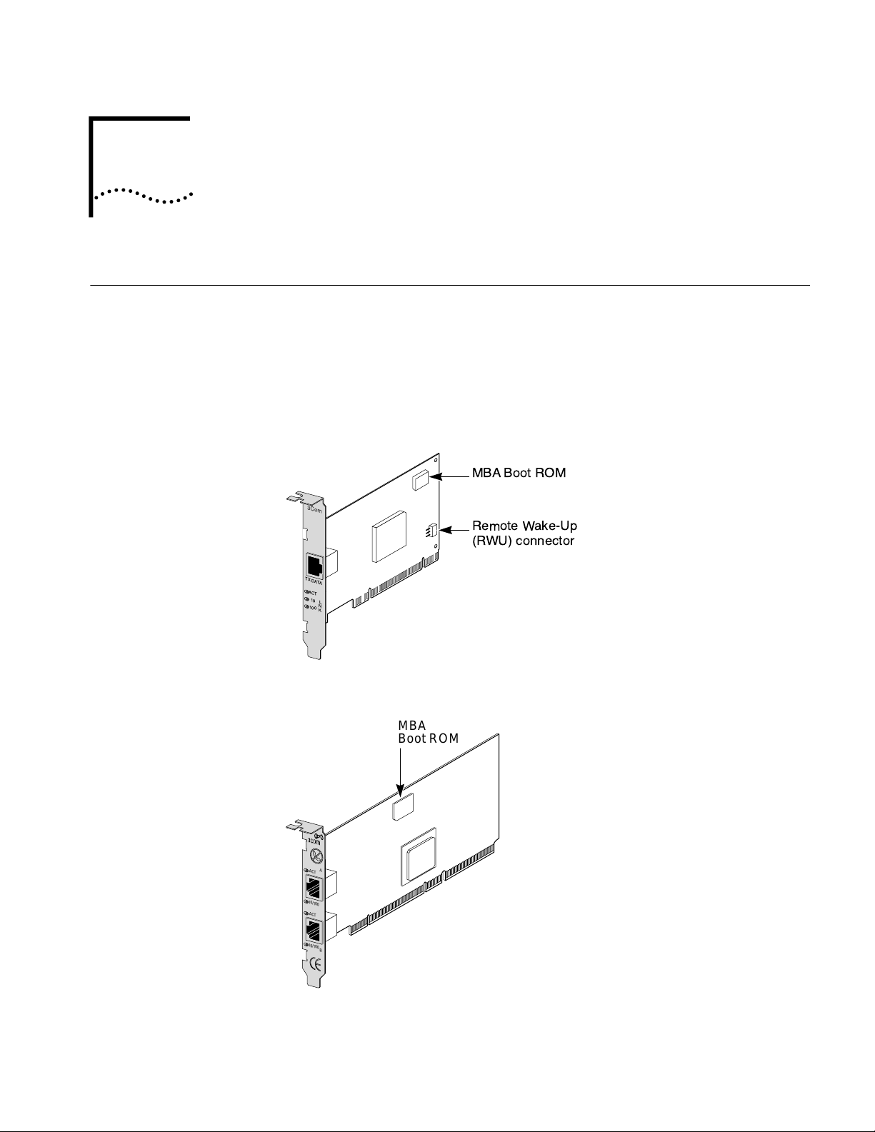
Figure 1 EtherLink Server 10/100 PCI NIC
MBA Boot ROM
Remote Wake-Up
(RWU) connector
TX DATA
ACT
10
L
N
100
K
Figure 2 Dual Port EtherLink Server 10/100 PCI NIC
MBA
Boot ROM
A
ACT
10/100
ACT
10/100
B
Page 8

2 CHAPTER 1: INTRODUCTION
Each NIC supports these features:
■ Advanced Server Features—Improve network performance, management, and
control.
■ Hot Plug NIC Installation—Lets you add a new NIC or remove and replace a NIC
without turning off power to the computer.
■ Remote Wake-Up (Single Port Models Only)—Lets you power-on a computer
remotely for after-hours administration.
■ Integrated boot ROM (through port A on 3C982-TXM) with Managed PC Boot
Agent (MBA) Software—Adds management capabilities by enabling the
computer to boot from another computer, rather than from its local drive.
■ Desktop Management Interface (DMI) 2.0—Enables managed computers and
net computers to report details about themselves and their peripheral devices
across the network to a DMI 2.0-compliant management application.
■ Remote System Alerts (heartbeat packets)—Can signal a possible computer
power loss or theft.
Advanced Server Features
Bidirectional
Load Balancing
3Com DynamicAccess technology advanced network software adds intelligence to
the NIC to improve network performance, management, and control.
DynamicAccess server features relieve network congestion and ensure high
performance and maximum bandwidth availability.
■ Self-healing drivers (SHDs) detect common error conditions and correct them
while maintaining server link performance.
■ Bidirectional load balancing groups share the network load over resilient server
links (RSLs) that keep traffic flowing both into a server and out of a server even
if a NIC in a group is temporarily disconnected.
■ VLANs (IEEE 802.1Q multiple virtual LANs) let you divide network segments
into logical partitions that simplify configuration changes, organize work
groups efficiently, help to control traffic, and provide extra security.
■ Traffic prioritization (IEEE 802.1p/Q)—Ensures that business-critical and
delay-sensitive traffic (such as multimedia applications) has priority over normal
data.
For detailed information on DynamicAccess technology products, go to:
http://www.3com.com/dynamicaccess
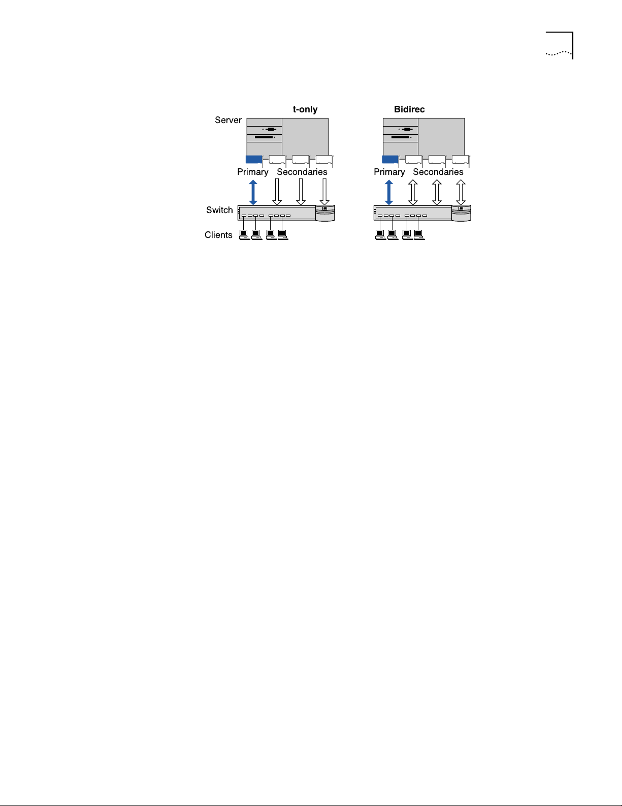
Bidirectional load balancing maximizes bandwidth at the server through the use of
multiple parallel resilient server links (RSLs) that share the network load.
An RSL consists of two or more NICs that form a virtual NIC. Each virtual NIC has
multiple physical NICs bound to it, forming a group. Each NIC in a group uses the
same protocols and frame types. One NIC is designated the primary NIC and the
others secondary NICs.
Page 9
Advanced Server Features 3
Clients
Bidirectional
Server
Primary
Secondaries
Transmit-only
Primary
Secondaries
Switch
¨ ¨
Figure 3 Types of Load Balancing Arrangements
Self-Healing Drivers Self-healing drivers (SHDs) work together with RSLs to maintain the network
connection. An SHD monitors the NIC continuously for error conditions and
makes corrections. These corrections can include resetting the NIC, rebuilding
software data structures, temporarily disabling features, or transferring all network
traffic to secondary NICs (termed a failover event). An SHD can also continuously
monitor the status of the physical NICs in a virtual NIC group before and after
failover. Errors and actions are reported to the system console and to the system
log file. Error threshold values can be configured at any time.
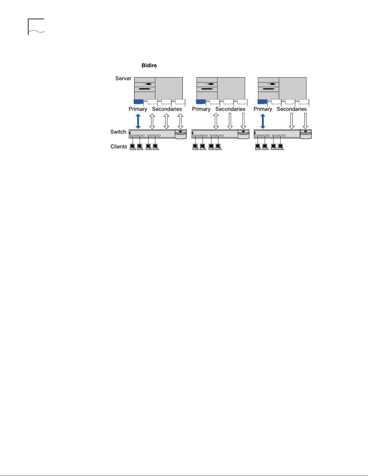
Failover In addition to load balancing, RSLs provide failover fault tolerance between a
server and a switch—if one NIC in a group fails, the others assume the network
load of the failed NIC. The failover behavior of secondary NICs depends on how
you set load balancing:
■ In a transmit load balancing arrangement, the primary NIC is the only one that
receives packets. If the primary NIC fails, a secondary NIC assumes the
configuration profile, network traffic, and active status of the failed
primary NIC.
■ In a bidirectional load balancing arrangement, all NICs receive packets. If any
NIC fails, receive load balancing is disabled, and the other NICs continue
transmit-only load balancing activity. Receive load balancing is restored when
new connections are established with clients.
Bidirectional load balancing is restored after a failure when applications create
new connections and new clients log in.
Page 10
4 CHAPTER 1: INTRODUCTION
Figure 4 Bidirectional Load Balancing Failover
Bidirectional
load balancing
Server
Primary failure Secondary failure
Switch
Clients
Primary
Secondaries
Primary
¨ ¨ ¨
Secondaries
Primary
Secondaries
VLANs A VLAN is a group of location-independent and topology-independent devices
that communicate as if they were on the same physical LAN. Network devices on
different LAN segments and of different media types can be members of the same
VLAN. Membership in a VLAN is determined by a VLAN tag that is transmitted
with the Ethernet frame for use by a switch.
With VLANs, you can define a network according to:
■ Organizational groups—For example, you can have one VLAN for the
Marketing department and one for the Finance department.
■ Application groups—For example, you can have one VLAN for e-mail users and
one for multimedia users.
Implementing VLANs on a network has these advantages:
■ It eases the change and movement of devices on IP networks.
With traditional IP networks, if users move to a different IP subnet, the IP
addresses of each workstation must be updated manually. With VLANs
installed, if an end station on VLAN 1 is moved to a port elsewhere on the
network, you need only to specify that the new port is on VLAN 1.
■ It helps to control traffic.
With traditional networks, congestion can be caused by broadcast traffic that is
directed to all network devices whether they require it or not. Each VLAN can
be set up to contain only those devices that need to communicate with each
other, increasing network efficiency.
■ It provides extra security.
Devices within each VLAN can communicate only with member devices in the
same VLAN. If a device in VLAN 1 needs to communicate with devices in
VLAN 2, the traffic must cross a router.
The DynamicAccess technology multiple VLAN capability supports IEEE 802.1Q
VLAN tagging and works with any switch that is compliant with IEEE 802.1Q
specifications. See your Ethernet switch documentation for more information on
IEEE 802.1Q VLANs.
Page 11

Hot Plug NIC Installation 5
Server Features Using
Other NICs
Hot Plug NIC Installation
Remote Wake-Up (Single Port Models Only)
Two foreign NICs (two that are not 3Com EtherLink Server NICs) are allowed per
server. For guidelines on using foreign NICs, see these topics:
■ Windows NT and Windows 2000—Planning Groups and VLANs on page 17.
■ NetWare—Planning the Configuration on page 34.
If your computer supports PCI hot plug specifications, you can add a new 3Com
NIC or remove and replace a 3Com NIC without turning off power to the
computer. Hot plug NIC installation allows you to expand connections without
taking the computer out of service and makes troubleshooting faster and easier
because you do not need to wait for the computer to reboot.
For instructions on performing a hot plug NIC installation, refer to your computer
documentation and to the HOTPLUG.TXT file in the HELP directory on the 3Com
EtherLink Server CD.
Remote Wake-Up is the ability to remotely power-on a computer for after-hours
administration.
If the computer is compliant with PCI 2.2, Remote Wake-Up is automatically
enabled through the PCI bus. If the computer is compliant with PCI 2.1, Remote
Wake-Up support is enabled by connecting a Remote Wake-Up cable from the NIC
Remote Wake-Up (RWU) connector to a 3-pin Remote Wake-Up connector on the
computer motherboard.
Managed PC Boot Agent (MBA) Software
The following items are needed to use Remote Wake-Up:
■ Management application that supports Remote Wake-Up
■ BIOS that supports Remote Wake-Up
■ PCI 2.2-compliant bus or a 3-pin Remote Wake-Up connector on the computer
motherboard and a 5-volt standby power supply unit rated at a minimum of
375 milliamperes
■ A power supply in the computer that can support multiple Remote Wake-Up
devices (to use multiple NICs as Remote Wake-Up NICs in the same computer)
If you are unsure whether the computer meets the requirements listed above, refer
to the computer documentation or contact the computer manufacturer.
For more information on Remote Wake-Up, including a list of computers that
currently support this feature, go to:
http://www.3com.com/partners/acpi
The Managed PC Boot Agent (MBA) software adds management capabilities to
the NIC, enabling the computer to boot from the server, rather than from its
local drive.
This preboot support allows you to use management applications to perform the
following tasks remotely:
■ Install and configure a new computer that has never been connected to the
network.
Page 12

6 CHAPTER 1: INTRODUCTION
■ Upgrade software.
■ Configure or reconfigure multiple systems simultaneously.
■ Scan for viruses.
■ Back-up hard drives and perform disaster recovery tasks.
For information on configuring the MBA to boot from the network, see
Configuring the Managed PC Boot Agent (MBA) on page 45.
For detailed information on the MBA, see the Managed PC Boot Agent User
Guide, located with the MBA software on the 3Com EtherLink Server CD.
Desktop Management Interface (DMI) 2.0
DMI 2.0 enables managed computers and net computers to report details about
themselves and their peripheral devices across the network to a DMI
2.0-compliant management application.
A network administrator can then use this information to configure and manage a
client or server computer remotely.
For instructions on installing the 3Com DMI Agent, see Installing the
3Com DMI Agent on page 59.
For more detailed information on DMI, go to:
http://www.3com.com/managedpc
Remote System Alerts The NIC can be configured to continuously transmit a packet to an alert target
management station. If the management station fails to receive the regularly
scheduled packet, an alert can be triggered that signals a possible computer
power loss or theft.
The NIC can also transmit a workgroup keep-alive packet periodically while the
computer is in a sleep state. This packet prevents the computer workstation
address from being aged-out of switch router tables.
Page 13
INSTALLING AND CONNECTING THE NIC
2
Safety Precautions Observe the following safety precautions:
WARNING: Computers operate with voltages that can be lethal. Before
removing the cover, turn off the computer and unplug it. Disconnect all cables
that are connected to the main system unit. Remove jewelry from your hands
and wrists. Use insulated or nonconductive tools.
CAUTION: The NIC is packed in an antistatic container to protect it during
shipment. Do not touch the components or any metal parts on the NIC, except
for the backplate. To avoid damaging the NIC or the computer, reduce static
electricity on your body by wearing an electrostatic discharge wrist strap attached
to the chassis or by touching an unpainted metal part of the chassis before
unplugging the computer and before handling the NIC.
Installation Requirements
CAUTION: Install the NIC in a PCI slot that conforms to PCI 2.1 or higher
specifications. Do not attempt to install the NIC in an ISA or EISA slot. Doing so
may damage the NIC and the computer.
WARNING: Make sure that the computer power cord is unplugged. Only
properly trained and authorized personnel should perform service. Contact the
computer manufacturer for information about safe service techniques.
The following items are required for hardware and software installation:
■ NIC—At least one 10/100 NIC.
■ Processor—Intel-based CPU (Pentium-class processor).
■ Server RAM—128 megabytes minimum; 256 megabytes recommended.
■ PCI slot—For each NIC, one bus master slot that conforms to PCI 32/64-bit
specifications, revision 2.1 or 2.2.
■ Drive—CD-ROM.
■ Cable—Category 5 UTP (for 100 Mbps operation).
■ Connector—RJ-45, one or two ports.
■ Software—One 3Com EtherLink Server CD with DynamicAccess technology
software and network drivers.
Page 14

8 CHAPTER 2: INSTALLING AND CONNECTING THE NIC
■ Operating system—Base drivers and DynamicAccess software are available
for the following operating systems:
■ Microsoft Windows NT version 4.0 with the most recent Service Pack
available from Microsoft technical support (www.microsoft.com).
■ Microsoft Windows 2000 with the most recent Service Pack available from
Microsoft technical support (www.microsoft.com).
■ Novell NetWare version 4.2 or 5.x with the most recent patches and
updates available from Novell technical support (www.novell.com).
Base drivers are also available for the following operating systems:
■ SCO UnixWare 7 available on the 3Com Web site
(http://support.3Com.com/infodeli/tools/nic/SCO.htm).
■ SCO OpenServer 5 available on the 3Com Web site
(http://support.3Com.com/infodeli/tools/nic/SCO.htm).
■ Linux available on the 3Com Web site
(http://support.3Com.com/infodeli/tools/nic/linux.htm).
Check the 3Com Web site (http://support.3Com.com/infodeli/tools/nic) for other
supported drivers.
Preparing the NIC and the Computer
■ Computer BIOS—Latest version. Contact the computer manufacturer
to verify.
■ Remote Wake-Up—For requirements, see Remote Wake-Up (Single Port
Models Only) on page 5.
Observe the precautions listed in Safety Precautions on page 7. Follow these
preparation steps:
1 Decide if you want to use the Remote Wake-Up feature.
If you want to use the Remote Wake-Up feature on a computer that is compliant
with PCI 2.1, you must obtain a Remote Wake-Up cable for the NIC (for details,
see Remote Wake-Up (Single Port Models Only) on page 5). If the computer is
compliant with PCI 2.2, Remote Wake-Up is automatically enabled through the
PCI bus and no Remote Wake-Up cable is required.
2 Make sure that cable requirements are met.
The RJ-45 port provides a 10 Mbps or 100 Mbps connection automatically,
depending on the speed of the connected hub or switch.
The following table shows the cable requirements and maximum network cable
lengths for the RJ-45 port.
Maximum
Network Environment Cable Required
10 Mbps (10BASE-T) Category 3, 4, or 5 unshielded
twisted-pair
100 Mbps (100BASE-TX) Category 5 unshielded twisted-pair 100 m (328 ft)
Cable Length
100 m (328 ft)
Page 15

Installing and Connecting the NIC 9
3 Unpack and inspect the NIC for damage.
4 Exit all open applications and user processes.
5 Turn off the power to the computer and attached devices.
6 Unplug the power cables from the power source.
7 Remove the computer cover.
8 Locate an empty, nonshared bus-mastering PCI slot and remove its slot cover. Save
the screw, if there is one.
Do not install the NIC in a shared PCI slot. Avoid any PCI slot next to an ISA slot.
This is often a shared slot and does not support bus mastering.
If you do not know how to identify a PCI slot, check the computer documentation
or ask the system administrator.
If you are planning to install the Remote Wake-Up cable, choose an empty PCI slot
that is close to the matching connector on the computer motherboard. The
Remote Wake-Up cable is required only if the computer is compliant with PCI 2.1
and you want to use the Remote Wake-Up. The cable is not required if the
computer is compliant with PCI 2.2.
9 Write down the MAC address of the NIC and note the relative position of the
intended PCI slot.
Installing and Connecting the NIC
This information is helpful when you are installing the network drivers and
connecting the cables to the hub or switch. The MAC address is the 12-digit
hexadecimal number printed on the small bar code label on the component side
of the NIC.
The next step is to install the NIC in the computer and connect it to the network.
Observe the safety precautions listed in Safety Precautions on page 7.
Prepare the NIC and the computer as described in Preparing the NIC and the
Computer on page 8.
The following instructions apply to installing the NIC in most computers. If these
instructions are not appropriate for your computer, refer to the documentation
that accompanied the computer.
Page 16
10 CHAPTER 2: INSTALLING AND CONNECTING THE NIC
TX DATA
ACT
10
100
L
N
K
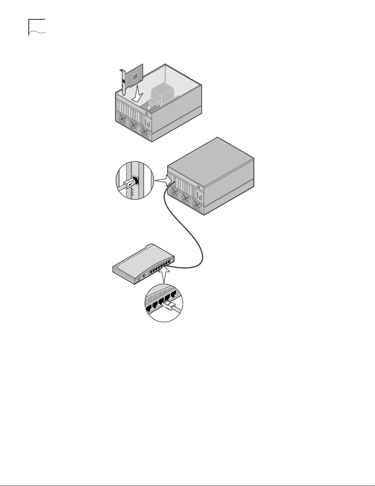
Figure 5 Installing and Connecting the NIC
+
–
1 Carefully insert the NIC into an empty PCI slot.
Press firmly to ensure that the NIC is fully seated in the slot. Secure the NIC with
the screw if you removed one earlier.
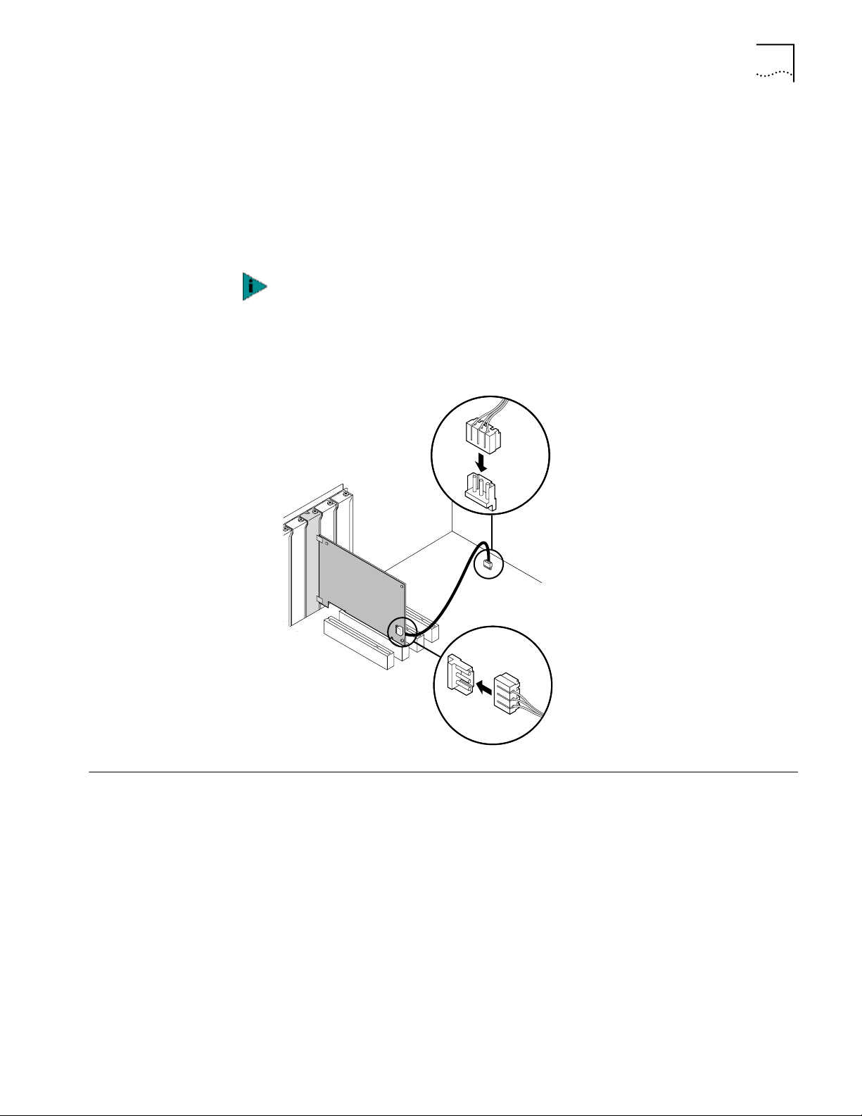
2 Follow these steps only if you need to connect a Remote Wake-up cable:
■ Make sure that the NIC is properly installed in a PCI slot.
■ Insert the Remote Wake-Up cable in the RWU connector on the NIC.
Twist the cable two times before attaching the cable to the computer.
■ Attach the other end of the cable to the connector on the computer
motherboard. Refer to the computer documentation if you need help
locating the connector.
3 Replace the computer cover and plug in the power cord.
Do not turn on the power to the computer.
Page 17
Installing Software 11
4 Plug the RJ-45 connector on the twisted-pair network cable into an RJ-45 port on
the NIC backplate.
If you are installing a dual port NIC, plug the first cable into Port A on the NIC
backplate.
5 Connect the other end of the network cable to an active network port.
The next step is to install the software.
If your site network installation procedures require you to verify that installed
hardware is functional before you install software, run the 3C90XCFG.EXE DOS
diagnostics program before installing the driver. This program is located on the
3Com EtherLink Server CD.
Figure 6 Connecting a Remote Wake-up Cable (PCI 2.1 only)
Installing Software See the following topics for requirements and instructions on installing software in
various operating systems:
■ Installing and Configuring in Windows on page 13
■ Updating Software in Windows on page 16.
■ Installing and Configuring in NetWare on page 27
Page 18

12 CHAPTER 2: INSTALLING AND CONNECTING THE NIC
Obtaining Installation
Diskettes
Creating Diskettes in
Windows
If your computer does not have a CD-ROM drive, access a computer that has a
CD-ROM drive and use the installation utilities to create installation diskettes from
files on the 3Com EtherLink Server CD.
If you do not have access to a computer that has a CD-ROM drive, you can
download the drivers from the 3Com web site:
http://www.3com.com/
Use the installation utilities on the 3Com EtherLink Server CD to create installation
diskettes. The installation diskettes allow you to install drivers, diagnostics,
DynamicAccess technology server features, and associated text files. The
installation diskettes do not contain the user guide that is available on the 3Com
EtherLink Server CD.
You will need five blank formatted diskettes.
To create the installation diskettes:
1 Turn on the power to the computer and start Windows.
2 Insert the 3Com EtherLink Server CD in the CD-ROM drive.
3 On the Welcome screen, click on NIC Software.
4 Click Installation Utilities.
5 Click on Create Installation Diskettes.
6 Follow the prompts to copy files to the diskettes.
Page 19
INSTALLING AND CONFIGURING IN
3
Software Installation Requirements
Getting Help To display the Help system during the software installation, click Help on any
W
INDOWS
Before you install software, you may want to verify that the installed server NICs
are functional or change their configuration settings by running DOS diagnostics.
Use the 3C90XCFG.EXE program located on the 3Com EtherLink Server CD.
If you are installing the software during the installation of the network operating
system, see Installing a 3Com NIC While Installing the NOS on page 57.
For a list of installation requirements, see Installation Requirements on page 7.
The installation instructions assume you are using the Windows Auto Run
feature. If the Welcome screen does not come up automatically, you can perform
the installation by running begin.exe.
3Com window.
Installing in
Windows NT
Before you begin software installation:
■ Make sure that all installation requirements are met. See Installation
Requirements on page 7.
■ Install the hardware. See Installing and Connecting the NIC on page 9.
Use the following procedure to install the driver and diagnostics for the first time
in a computer that is running Windows NT. (If you are updating a previous
installation, see Updating Software in Windows on page 16.)
1 Boot the computer and start Windows NT.
2 Log in to the Windows NT Administrator account.
3 Insert the 3Com EtherLink Server CD in the CD-ROM drive.
4 From the Welcome screen, select NIC Software.
5 Click NIC Drivers and Diagnostics.
6 Follow the Wizard prompts.
7 Choose Typical or Custom Installation.
The Please Wait screen appears. After the installation is completed, an Update
dialog box appears.
Page 20

14 CHAPTER 3: INSTALLING AND CONFIGURING IN WINDOWS
8 Click OK.
The Setup Complete screen appears.
If your network environment uses the TCP/IP communications protocol, the
Microsoft TCP/IP Properties dialog box appears. Enter the information needed to
define an IP address. Continue after you have defined the TCP/IP settings.
9 Click Finish to complete the installation.
10 Click Exit.
11 Restart your computer for changes to take effect.
Installing in Windows 2000
Before you begin software installation:
■ Make sure that all software installation requirements are met. See Installation
Requirements on page 7.
■ Install the hardware. For instructions, see Installing and Connecting the NIC on
page 9.
Use the following procedure to install the driver and diagnostics for the first time
in a computer that is running Windows 2000. (If you are updating a previous
installation, see Updating Software in Windows on page 16.)
1 Reboot the computer, start Windows 2000, and log in to the Windows 2000
Administrator account.
The Windows 2000 Found New Hardware wizard detects the new NICs and
begins the driver installation.
2 Insert the 3Com EtherLink Server CD in the CD-ROM drive.
3 From the main menu, select NIC Software.
4 From the list on the left, click NIC Drivers and Diagnostics.
5 Follow the Wizard prompts.
6 Choose Typical or Custom Installation.
The Please Wait screen appears. After the installation is completed, an Update
dialog box appears.
Configuring SHD
Parameter Settings
Windows NT
7 Click OK
The Setup Complete screen appears.
8 Click Finish to complete the installation.
9 Click Exit.
Follow the procedure for your operating system.
1 Right-click My Network Places and select Properties from the menu.
2 In the next window, right-click a connection and select Properties from the menu.
3 Click Configure.
Page 21
Windows 2000
Configuring SHD Parameter Settings 15
4 In the NIC Properties window, click the Advanced tab.
5 In the Advanced window, you can configure the SHD parameters. Select a
parameter in the Property field and change its value in the Value field. Table 1
describes the SHD parameters. Default values are optimal for most networks.
1 From the Windows Start menu, select Settings/Control Panel.
2 Double-click the Network icon.
3 In the Network window, click the Adapters tab.
4 Double-click the adapter you want to modify
5 Double-click a parameter to change its value. Table 1 describes the SHD
parameters. Default values are optimal for most networks.
Slot numbers listed in the SHD Configuration window may not match those
labeled on the mother board
6 When you are finished, click OK.
7 Remove the 3Com EtherLink Server CD from the CD-ROM drive.
8 Restart the computer.
Table 1 SHD Parameters (Windows)
Range of Values
Field
Self Check
Level
Sampling
Window
Sampling Ratio 0–100 percent
Error Tolerance Low
Alert Type
(Windows NT)
(Defaults in Bold)
Off, Basic, Enhanced Basic level checking monitors Tx/Rx errors (see
0–65536 packets
0 disables sampling.
1024
50
Medium
High
Information
Warning
Error
Description
Sampling Window), link beat, and NIC hardware.
Enhanced level adds maintenance of valid data
structures and uses more CPU cycles. Basic level
checking is forced when RSL is enabled. Off disables
SHD.
This option specifies the number of Tx/Rx packets to
be sampled for carrier lost, late collisions, jabbers,
CRC, overruns, underruns, and bus contention
errors. Setting the Sampling Window to 0 effectively
disables all checking.
Sampling Ratio establishes a rate of error
accumulation. Every second, the error counters are
diminished by the Sampling Ratio. The larger the
Sampling Ratio, the more recent are the
accumulated errors.
Error Tolerance specifies threshold levels for Tx/Rx
errors. An RSL failover or NIC reset occurs when the
threshold is exceeded during the sampling period.
Low = 5 of each error category
Medium = 50 of each error category
High = 100 of each error category
Double-click to enable or disable alert types. Enabled
types are reported to the Windows System Events
monitor.
Page 22

16 CHAPTER 3: INSTALLING AND CONFIGURING IN WINDOWS
Table 1 SHD Parameters (Windows) (continued)
Verifying Successful Installation
Windows NT
Windows 2000
Field
SHD Inform
messages
SHD Warning
messages
SHD Error
messages
(Windows 2000)
Range of Values
(Defaults in Bold) Description
Enabled
Disabled
Select a parameter in the Property field and change
its value in the Value field. Enabled types are
reported to the Windows System Events monitor.
Follow the procedure for your operating system.
1 Double-click the My Computer icon, then the Control Panel icon, and then the
Network icon.
2 Select the Adapters tab.
3 Make sure that the name of the NIC appears in the list of network adapters.
1 Right-click My Network Places and select Properties from the menu.
Updating Software in Windows
Windows NT
2 Check connections in the Network and Dial-up Connections window.
The following procedures update a previous installation of the network driver and
NIC diagnostics software in Windows.
1 Boot the computer and start Windows NT.
2 Log in to the Windows NT Administrator account.
3 Insert the 3Com EtherLink Server CD in the CD-ROM drive.
4 From the Welcome screen, select NIC Software.
5 Click NIC Drivers and Diagnostics.
The Please Wait screen appears.
6 Follow the Wizard prompts.
7 Choose Custom Installation.
8 Select the desired installation option.
9 Click Next.
10 Choose any advanced features you would like set.
11 Click Next.
12 Click OK.
13 Click Finish to complete the installation.
Page 23

Windows 2000
DynamicAccess Server Features 17
14 Click Exit.
15 Restart your computer for changes to take effect.
After you restart the computer, you may wish to configure self-healing drivers. To
do so, bring up the Adapters tab in the Network window, select a NIC, and click
Properties. For details on the SHD parameters, see SHD Parameters (Windows) on
page 15.
1 Reboot the computer, start Windows 2000, and log in to the Windows 2000
Administrator account.
The Windows 2000 Found New Hardware Wizard detects the new NICs and
begins the driver installation.
2 Insert the 3Com EtherLink Server CD in the CD-ROM drive.
3 From the Welcome screen, select NIC Software.
4 Click NIC Drivers and Diagnostics.
5 Follow the Wizard prompts.
DynamicAccess Server Features
6 Choose Custom Installation.
7 Select the desired installation option.
8 Click OK
The Setup Complete screen appears.
9 Click Finish to complete the installation.
10 Click Exit.
DynamicAccess technology server features allow you to configure load balancing
groups and virtual LANs (VLANs). The features are described in Advanced Server
Features on page 2.
The following DynamicAccess technology server features are available for
NIC groups in Windows:
■ Bidirectional load balancing
■ RSL failover
■ Multiple VLANs
The examples in this section illustrate typical actions you might take in the course
of maintaining a DynamicAccess server configuration in Windows.
Planning Groups and
VLANs
Consider these items when planning groups and VLANs:
■ Decide whether you want to use bidirectional load balancing, or transmit load
balancing.
To use bidirectional load balancing, you must assign a dedicated IP address for
each load balancing group. This address must be unique (not used elsewhere
on the network). For details, see Specifying a Dedicated IP Address on page 21.
Page 24

18 CHAPTER 3: INSTALLING AND CONFIGURING IN WINDOWS
■ Decide which NICs are to be part of each group. Each group must
include at least two NICs.
■ Decide whether you want to use a foreign NIC in one of the groups.
Two foreign NICs (two that are not 3Com EtherLink Server NICs) are allowed in
one group per server.
■ Decide which NIC is to be the primary NIC in each group.
■ You can specify failover from a Gigabit NIC to a 10/100 NIC. To ensure optimal
performance, this type of failover requires that you disable load balancing for
the group.
■ For the best failover performance, turn the spanning tree feature off at
switches that are connected directly to the server. If the spanning tree feature is
turned on, a failover may be delayed up to 30 seconds while the switch
processes the spanning tree algorithm.
■ Plan the cable changes required to connect each primary NIC and all secondary
NICs to the same network segment.
■ Observe the recommended support limit of four groups per server.
■ The following guidelines apply to groups under Windows 2000:
802.1p Support Property—The value of the Windows 2000 802.1p Support
property must be the same for all NICs in a group. For example, if this property
is enabled for the primary NIC, it must also be enabled for all other NICs in the
group.
Microsoft Task Offload Support—It is possible to form a group of NICs that
have different levels of support for Microsoft Task Offload features (TCP
Checksum, TCP Segmentation, and IP Sec). In this case, the offload support is
limited to the features supported by all NICs in the group. For example, if two
NICs in a group support all offload features but one NIC supports only TCP
Checksum, then offload support for the group is limited to TCP Checksum.
■ Observe these VLAN configuration guidelines:
■ Assign a VLAN ID number to each VLAN. If you are not using a DHCP server,
each VLAN that is using IP services requires an IP address and subnet mask.
■ DynamicAccess software supports as many as 16 VLANs per server.
■ Each VLAN bound to TCP/IP must exist on a separate IP subnet. DHCP
servers used to allocate IP addresses must be located on the same IP subnets
as the VLANs.
■ Each VLAN bound to the IPX/SPX protocol must use a unique network
number.
■ Under Windows 2000, when VLANs are enabled, the Windows 2000
802.1p Support property must be disabled for all the underlying miniports.
■ A minimum of 128Mb of RAM is required for multiple VLAN configurations
(up to a maximum of 16 VLANs). You can improve overall system
performance with VLANs by increasing the physical RAM, the virtual
memory page size, or both.
Page 25

DynamicAccess Server Features 19
Installing
DynamicAccess
Software
Configuring Server
Features
Use the following procedure to install DynamicAccess technology server features
in a computer that is running Windows NT or Windows 2000.
Installing teaming software from multiple vendors may cause problems with your
system. Before installing DynamicAccess software, uninstall any other teaming
software you may have previously installed on your computer.
1 Insert the 3Com EtherLink Server CD in the CD-ROM drive.
2 From the Welcome screen, select NIC Software.
3 Click DynamicAccess Technology.
4 Click Install DynamicAccess Server Software.
5 Select Windows 2000 or Windows NT installation.
6 Click OK to Install the DynamicAccess server software.
7 Restart your system.
When DynamicAccess server features are installed, NICs bind to the
DynamicAccess protocol and real protocols bind to the DynamicAccess Miniport.
Do not modify these bindings.
The DynamicAccess server features window contains tabs for these windows:
■ In the Load Balance/RSL window, you can create and change Load
Balancing/RSL groups. The NICs in a group work together to route traffic
efficiently and to recover from failures.
■ In the VLANs window, you can set up virtual LANs. All groups listed in the
Load Balance/RSL window also appear as groups in the VLAN window. Any
ungrouped NICs in the Load Balance/RSL window are also listed in the VLAN
window.
Windows NT
Start DynamicAccess server features under Windows NT as follows:
1 Log in to the Windows NT Administrator account.
2 From the Windows Start menu, select Settings/Control Panel.
3 Double-click the DynamicAccess Server icon.
The DynamicAccess Resilient Server Link/Load Balance/VLAN Configuration
window appears. Click the appropriate tab to configure server features.
Windows 2000
Access DynamicAccess server features through the Windows 2000 Network and
Dial-up Connections window as follows:
1 Log in to Windows 2000 with administrator privileges.
2 Launch the Windows 2000 Network and Dial-up Connections window.
3 Select a Local Area Connection icon.
4 Click the right mouse button and select Properties.
The Local Area Connections Properties window appears.
Page 26

20 CHAPTER 3: INSTALLING AND CONFIGURING IN WINDOWS
5 Click the General tab.
6 In the General window, select DynamicAccess Protocol and click Properties.
The DynamicAccess Protocol Properties window appears. Click the appropriate tab
to configure server features.
Creating a Group
1 Click the Load Balance/RSL tab.
2 In the Load Balance/RSL window, click Create Group.
3 In the Create Group dialog box, type a group name.
4 Set the load balancing:
To enable transmit load balancing—Check the Transmit Load Balance Enabled
box.
To enable bidirectional load balancing—Check both the
Transmit Load Balance Enabled box and the Receive Load Balance Enabled box.
Enter only the Host ID bytes required for a dedicated IP address.
Do not use the group IP address as the dedicated IP address.
For example:
Byte 1 Byte 2 Byte 3 Byte 4
Class A Network ID Host ID
24 1 253
Class B Network ID Host ID
2 253
Class C Network ID Host ID
253
See Specifying a Dedicated IP Address for more information on the dedicated IP
address.
To disable all load balancing—Clear the Receive Load Balance Enabled and the
Transmit Load Balance Enabled check boxes.
5 Click OK.
The name of the new NIC group appears in the Load Balancing/RSL Groups list
box.
Page 27

Adding NICs to a Group
DynamicAccess Server Features 21
1 Click the Load Balance/RSL tab.
2 In the Load Balance/RSL window:
■ Select a group from the Load Balancing/RSL Groups list.
■ Select a NIC from the Network Interface Cards list.
3 Click Add NIC.
The NIC appears as part of the group in the Load Balancing/RSL list box.
If you click Add NIC repeatedly, NICs are added to the group in the order that they
are listed after the first NIC you selected.
Specifying a Dedicated
IP Address
Bidirectional load balancing requires that you specify a dedicated IP address for the
load balancing group. This address specifies a Network ID and a Host ID, and it
must be unique (not used elsewhere on the network). For example:
Byte 1 Byte 2 Byte 3 Byte 4
Class A Network ID Host ID
125 24 1 253
Class B Network ID Host ID
139 25 2 253
Class C Network ID Host ID
193 26 3 253
You can specify the dedicated IP address in the Create Group or Group Properties
dialog boxes. You cannot specify the bytes for the Network ID; they are fixed.
Specify the bytes for the Host ID for various classes of subnets as follows:
Class Byte 1 Specify only bytes
A 126 2, 3, and 4 (the three rightmost boxes).
B 128–191 3 and 4 (the two rightmost boxes).
C 192–223 4 (the rightmost box).
Page 28

22 CHAPTER 3: INSTALLING AND CONFIGURING IN WINDOWS
Changing an IP Address If another device is using the dedicated IP address of a bidirectional load balancing
group, you must change either the IP address of the load balancing group or the IP
address of the other device. Use the appropriate procedure below:
Creating a VLAN
Changing the IP Address
of the Other Device
Changing the Dedicated
IP Address of the Group
After you change the IP address of the other device, restart receive
load balancing as follows:
1 In the Load Balancing/RSL window, select the group that had
the duplicate address.
2 Click Properties.
3 In the Properties dialog box, click OK.
4 In the Load Balancing/RSL window, click OK to exit the window
and restart receive load balancing.
1 In the Load Balancing/RSL window, select the group that has
the duplicate address.
2 Click Properties.
3 In the Properties dialog box, enter a new IP address and click
OK.
4 In the Load Balancing/RSL window, click OK to exit the window
and restart receive load balancing.
1 Click the VLANs tab.
2 In the VLANs window, select a NIC or group from the VLANs list and click Create
VLAN.
3 In the VLAN ID dialog box, type a VLAN ID number and click OK.
Legal VLAN ID numbers are 1–511 and from 768–4095. Numbers in the range
512–767 are reserved.
The new VLAN is added to the VLANs list.
Windows NT—Restart the computer when the software prompts you to do so.
Windows 2000—If you create more than one VLAN, assign a VLAN ID number to
each VLAN as follows:
■ Right-click My Network Places and select Properties from the menu.
■ In the next window, right-click a VLAN and select Properties from the menu.
■ Click Configure.
■ In the NIC Properties window, click TCP/IP.
■ In the next window, configure the IP address and subnet mask.
Page 29

DynamicAccess Server Features 23
Specifying Traffic
Priorities (Windows NT
4.0 Only)
You can use the DynamicAccess Software Setup window to specify traffic
priorities.
1 Double-click the 3Com DynamicAccess icon in the Windows Control Panel.
The DynamicAccess Software Setup window appears.
2 Click the appropriate tab:
■ Traffic Prioritization—Prioritize applications to ease bottlenecks in the
network and allow critical applications to take network precedence. You can
turn traffic prioritization on or off independently for:
■ Each NIC that is not in a group and does not have VLANs
■ Each group that does not have VLANs
■ Each VLAN
■ Each virtual NIC (NIC, group, or VLAN) shown in the Traffic Prioritization
control panel
■ Administration—Set DynamicAccess control panel access, set VLAN options,
enable efficient multicast control, and enable the prioritizing of multicast
traffic.
For detailed information on DynamicAccess software, go to:
http://www.3com.com/dynamicaccess
Saving the
Configuration
Disabling Load
Balancing for a Group
To save and exit, click OK.
A prompt asks whether you want to configure traffic prioritization. If you click Yes,
the DynamicAccess Software Setup window appears.
To exit without saving the configuration, click Cancel.
1 Click the Load Balance/RSL tab.
2 In the Load Balance/RSL window:
■ Select a group from the Load Balancing/RSL Groups list.
■ Click Properties.
3 In the Group Properties dialog box:
To disable receive load balancing only—Clear the Receive Load Balance
Enabled check box.
To disable all load balancing—Clear the Receive Load Balance Enabled and the
Transmit Load Balance Enabled check boxes.
4 Click OK.
Page 30

24 CHAPTER 3: INSTALLING AND CONFIGURING IN WINDOWS
Changing the Primary
NIC
Removing a NIC from a
Group
Deleting or Editing a
VLAN
The first NIC added to an empty group is automatically designated the primary
NIC. NICs added subsequently are designated as secondary NICs. Primary status is
indicated by a P icon at the beginning of the NIC name. When there are more than
one NIC in a group, you can change the primary NIC as follows:
1 Click the Load Balance/RSL tab.
2 In the Load Balance/RSL window, select a secondary NIC from the Load
Balance/RSL Groups list.
3 Click Select Primary.
The NIC you selected becomes the primary NIC.
1 Click the Load Balance/RSL tab.
2 In the Load Balance/RSL window, select a NIC from a group in the Load
Balancing/RSL Groups list.
3 Click Remove NIC.
When a VLAN is selected, you can delete it or edit its properties.
1 Click the VLANs tab.
Displaying NIC
Properties
Displaying Group
Properties
2 In the VLANs window, select a VLAN.
To delete the selected VLAN, click Delete VLAN.
To edit the VLAN ID for the selected VLAN, click Edit VLAN.
1 Click the Load Balance/RSL tab.
2 In the Load Balance/RSL window, select a NIC.
3 Click Properties.
The NIC Properties window appears, showing the properties of the selected NIC.
1 Click the Load Balance/RSL tab.
2 In the Load Balance/RSL window, select a group in the Load Balancing/RSL Groups
list box.
3 Click Properties.
The Group Properties window appears, showing the properties of the selected
group.
Specifying Failover from
Gigabit to 10/100 PCI
You can specify failover from a Gigabit NIC to a 10/100 NIC. To ensure optimal
performance, this type of failover requires that you disable load balancing for the
group.
Page 31

DynamicAccess Server Features 25
Troubleshooting a Load
Balancing Configuration
Use the troubleshooting tips in Table 2 to solve problems that may occur in a load
balancing configuration.
To access a database of technical information that can help you diagnose and
solve NIC installation, configuration, and upgrade problems, go to:
http://knowledgebase.3com.com
Table 2 Troubleshooting Load Balancing In Windows
Symptom Tip
Receive load balancing fails to begin
functioning.
Receive load balancing stops
functioning.
Reconnecting cables does not restore
load balancing.
Receive load balancing does not
function across a router.
Check the Group Properties to verify that the
dedicated IP address has been entered. If no address
appears in the Group Properties dialog box, enter one
to enable receive load balancing.
Cables may be disconnected, or there may be other
hardware problems. Reconnect or change the cables.
Correct any other hardware problems. Bidirectional
load balancing is restored after this type of failure
when applications create new connections and new
clients log in.
Check the event log for a duplicate IP address. If
another device is using the dedicated IP address of a
load balancing group, change one of the IP addresses.
See “Changing an IP Address” for instructions.
Receive load balancing across a router is not
supported. Clients across the router cannot use
receive load balancing, but clients within the subnet
get higher throughput from receive load balancing.
Changing Windows
2000 Property Settings
Identifying Windows
2000 Miniport and LAN
Connections
If you receive warnings about inconsistent property settings (for example, the
802.1p Support property) while creating a group, use the following procedure to
change a NIC property:
1 Right-click the My Computer icon and select Properties from the menu.
2 Click the Hardware tab, then click Device Manager.
3 Double-click Network Adapters.
4 Right-click on the name of the appropriate NIC and select Properties from the
menu.
5 Click the Advanced tab.
6 Select the appropriate property from the list (for example, 802.1p Support).
7 Use the scroll list to change the property value.
8 Exit the Device Manager.
DynamicAccess miniport connections and NIC Local Area Connections are listed in
the Network and Dial-up Connections window. If a group or VLAN is associated
with a miniport, the group name and VLAN name appear in the miniport icon
name.
Page 32

Page 33

INSTALLING AND CONFIGURING IN
4
Software Installation Requirements
Netware Packet Receive
Buffers
N
ETWARE
Before you install software, you may want to verify that the installed server NICs
are functional or change their configuration settings by running DOS diagnostics.
Use the 3C90XCFG.EXE program located on the 3Com EtherLink Server CD.
The instructions in this topic demonstrate the fundamentals of setting up a sample
configuration. Setting up your own configuration may require a slightly different
sequence of tasks and different numbers of NICs.
If you are installing the software during the installation of the network operating
system, see Installing a 3Com NIC While Installing the NOS on page 57.
For a list of installation requirements, see Installation Requirements on page 7.
Follow these guidelines for NetWare 4.2 and 5.x:
The driver requires 200 packet receive buffers for each installed NIC. You must
increase the minimum and maximum packet receive buffers values by 200 for
each installed NIC. For example, if you install two NICs, increase the parameters in
the STARTUP.NCF file by 400 as follows:
Before installing NICs SET MINIMUM PACKET RECEIVE BUFFERS = 1000
SET MAXIMUM PACKET RECEIVE BUFFERS = 2500
After installing two NICs SET MINIMUM PACKET RECEIVE BUFFERS = 1400
SET MAXIMUM PACKET RECEIVE BUFFERS = 2900
Slot Numbers for
Multiple NICs
Obtaining Slot Numbers The NetWare driver installation program requires you to enter a PCI slot number
If you are installing more than one NIC on a server, you must know which NIC
corresponds to a given PCI slot to connect a cable from the NIC to the appropriate
port on the hub or switch. You can correlate slots with physical NICs by the NIC
MAC addresses. (The MAC address is written on a bar code label on the top
component side of the NIC.)
for each NIC. In older versions of NetWare software, the term slot number referred
to the physical slot in which the NIC was installed in the server. Now, the slot
number is a combination of the bus number, bus type, and the physical slot
number. The value of a slot number can be 10001 or larger.
Page 34

28 CHAPTER 4: INSTALLING AND CONFIGURING IN NETWARE
Follow this procedure to obtain slot numbers for a multi-NIC installation:
1 Install only one 3Com EtherLink Server NIC.
2 Follow the installation instructions in this chapter to load the 3Com EtherLink
Server CD, copy the driver, and load the driver.
You need not specify a slot number when only one NIC is installed.
3 In the Netware Console, issue a CONFIG command.
4 Write down the slot number that is listed for the installed 3Com EtherLink Server
NIC.
5 Install the second 3Com EtherLink Server NIC.
6 Follow the installation instructions in this chapter to install the driver on the
second NIC.
Each time you load the driver, the CONFIG command displays the slot numbers for
all the 3Com Server NICs in the system.
Installation and
Configuration
Instructions
Load the 3Com
EtherLink Server CD
Copy the Driver
With NetWare installed and the server up and running, complete the following
steps to install and configure the driver and DynamicAccess technology server
features on a NetWare file server.
In NetWare screens, use the arrow keys to select an item and then press Enter.
NetWare 4.2 Insert the CD in the CD-ROM drive and enter these commands:
load cdrom
cd mount ecd210p980x
NetWare 5.x Insert the CD in the CD-ROM drive and enter this command:
load cdrom
Wait for the message that states the CD is mounted successfully, and then
proceed to copy the driver.
1 Enter this command at the prompt:
NetWare 4.2: load install
NetWare 5.x: load nwconfig
2 In the Configuration Options screen, select Driver options.
3 In the Driver Options screen, select Configure network drivers.
4 In the Additional Driver Actions screen, select Select a driver.
The Select a Driver screen appears, listing all previously saved drivers in the system.
If this is the first installation of the 3Com server NIC driver, it does not appear in
this list
5 Press Insert.
A system message for selecting a disk drive appears.
6 Press F3.
Page 35

Installation and Configuration Instructions 29
7 Enter a path to the volume that contains the driver. For example:
ecd210p980x:/nwserver
The Select a Driver to Install screen appears with the 3Com EtherLink Server NIC
driver name highlighted.
8 Press Enter to select the driver.
9 Select Yes at the prompt to confirm the name of the driver to copy.
The installation program copies the driver to the appropriate server subdirectory.
The Configuration screen appears.
Specify the Slot Number You need not specify the slot number if you are installing only one NIC.
1 In the Configuration screen, select Slot Number.
2 Enter the slot number of the NIC that you want to install. For example:
10001
See Changing NetWare Driver Configuration Parameters for instructions on
changing other parameters in this screen.
Load the Driver
Set Up Another NIC
1 Select Save parameters and load driver.
The installation program loads the configured driver and then writes the
appropriate LOAD and BIND commands to the AUTOEXEC.NCF file.
The system assigns a network number.
2 Enter a network number, or press Enter to select the system-assigned number.
If no errors are encountered, the installation program asks whether you want to
select an additional network driver.
3 Select Yes to set up another NIC.
1 Follow the prompts for another NIC:
■ Select the driver
■ Enter the slot number
■ Save parameters and load the driver
2 Repeat the process for all NICs to be set up.
3 After all NICs are set up, press Esc several times to return to the Installation
Options screen.
Page 36

30 CHAPTER 4: INSTALLING AND CONFIGURING IN NETWARE
Install Server Features Two drivers are associated with DynamicAccess technology server features under
NetWare: SE and LBRSL.
1 From the Configuration Options screen select Product options.
2 Select Install a product not listed.
The following message appears:
Product will be installed from A:\. If you are installing
from floppy, insert the first diskette of the product you
want to install into the drive and verify that the path
above is correct.
Press <F3> to specify a different path;
Press <ENTER> to continue.
3 Press F3.
4 Enter this path:
ecd210p980x:\nwserver
The following message appears:
Product “3Com DynamicAccess Server Features” was found.
Verify that this is the product you want to install before
proceeding.
Configure Groups
Press <ENTER> to continue.
Press <ESC> to abort installation.
5 Press Enter.
The system copies the DynamicAccess technology server features software to the
SYS volume.
1 Press Esc to return to the Installation Options screen.
2 From the Configuration Options screen, select NCF files options (create/edit server
startup files)
3 Select Edit AUTOEXEC.NCF file.
4 Make the following changes to the AUTOEXEC.NCF file:
■ Add a command to load the SE and LBRSL drivers before any commands to
load LAN drivers. For example:
load se
load lbrsl
■ Add or verify the LOAD commands for the LAN drivers for all slot-frame
instances.
■ For each Load Balancing/RSL group, load the same protocols and frame
types on the primary and all secondary NICs.
■ On the primary NIC only, bind a protocol to each slot-frame instance.
■ Remove any protocol BIND commands from each secondary NIC.
Page 37

Installation and Configuration Instructions 31
■ For each group, add an LBRSL GROUP command to group the primary and
secondary NICs together. There can be only one LBRSL GROUP command
per group, and it must list the primary and all secondary NICs. Place this
command after the LAN driver.
If INETCFG is used, all adapters will have protocol bindings. You will have to
unbind all secondary adapters in the AUTOEXEC.NCF file.
To specify a load balancing group with resilient server links, use the LB option.
To specify a resilient server link group without load balancing, use the RSL
option.
For the LBRSL GROUP command syntax, see Server Feature Commands on
page 37.
For more information on maintaining the group configuration, see Configuring
Groups on page 34.
5 Save the AUTOEXEC.NCF file and return to the server prompt.
The sample AUTOEXEC.NCF file in Figure 7 shows a group of two NICs. The
primary NIC in slot 10001 is bound to a secondary NIC in slot 10002.
Verify the Installation
and Configuration
Figure 7 AUTOEXEC.NCF File for One Group of Two NICs
load se
load lbrsl
;Define primary NIC slot-frame instances
load 3c980 slot=10001 frame=ethernet_802.2 name=p1_802.2
load 3c980 slot=10001 frame=ethernet_ii name=p1_ii
;Define secondary NIC slot-frame instances
load 3c980 slot=10002 frame=ethernet_802.2 name=p2_802.2
load 3c980 slot=10002 frame=ethernet_ii name=p2_ii
;Bind protocols to primary NIC
bind ipx to p1_802.2 net=FF02
bind ip to p1_ii address=192.1.1.1 mask=ff.ff.ff.00
;Create a group with NIC 10001 primary and NIC 10002 secondary
lbrsl group lb 10001 10002
;To create a resilient server link group without load balancing (for
;use with NICs from manufacturers other than 3Com) use the rsl option:
;lbrsl group rsl 10001 10002
To verify that the driver has been properly loaded on the NetWare server, perform
the following procedure:
1 At the system prompt, enter:
load monitor
The NetWare Monitor screen appears.
2 From the Available Options menu, select LAN/WAN Drivers.
The Available LAN Driver menu appears. If the driver has been properly loaded, the
driver and frame types associated with the driver appear on this menu.
Page 38

32 CHAPTER 4: INSTALLING AND CONFIGURING IN NETWARE
3 Select a driver to view its associated statistics.
A functioning driver displays packets being sent and received.
To verify that the server is communicating over the network, perform the
following procedure:
1 Set up a NetWare client on a LAN supported by the server to be tested.
2 Log in or map to the server.
If you cannot log in or map to the server, the link is not functional.
If the link is functional, the following message appears on the server console:
Link integrity test for primary slot #XXXXX passed.
Changing NetWare
Driver Configuration
Parameters
You can change parameters from the NetWare installation program Configuration
screen. Table 3 lists the parameters shown on the Configuration screen.
Table 3 NetWare Installation Program Configuration Parameters
Range of Values
Parameter
Slot Number All PCI slot numbers
Node Address Default is
Log Message
Level
Receive
Checksumming
Transmit
Checksumming
SHD
Configuration
Check Level Basic Level Checking
Transmit/Receive
Error Threshold
Sampling
Window Size
(Defaults in Bold)
valid to the system
factory-assigned MAC
address.
Error messages logged
Message logging
disabled
Enabled
Disabled
Enabled
Disabled
Configure SHD
Use default
configuration
All Checking is Disabled
Enhanced Level
Checking
Basic and Enhanced
1–64000
50
0–64000 packets
0 = disabled
1024
Description
Represents the PCI slot number of the physical
NIC to be configured.
Leave blank to use factory-assigned default.
Determines which type of messages are
displayed to the system console and the
SYS:\SYSTEM\SYS$LOG.ERR file.
NetWare 5.x only. Select Enabled to allow the
NIC to perform checksum operations on
incoming packets.
NetWare 5.x only. Select Enabled to allow the
NIC to perform checksum operations on
outgoing packets.
Select Configure SHD to change self-healing
driver settings.
Appears when Configure SHD is selected. Basic
Level Checking monitors link beat, DMA FIFOs,
interrupt availability, bus contention errors,
internal NIC subsystems, and recoverable Tx/Rx
errors (CRC, Tx underruns, Rx overruns, late
collisions, jabbers). Enhanced Level Checking
maintains valid data structures and uses more
CPU cycles.
Appears when Configure SHD is selected.
Specifies threshold levels for Tx/Rx errors. A
failure is reported when the threshold is
exceeded during the sampling period.
Appears when Configure SHD is selected.
Specifies the number of Tx/Rx packets to be
sampled for late collisions, receive overruns,
transmit underruns, jabbers, and bus contention
errors. Automatically ages error count to ensure
that only recent errors are accumulated.
Page 39

Changing NetWare Driver Configuration Parameters 33
Follow these steps to change parameters:
1 From the Configuration screen, select Select/Modify driver parameters and
protocols.
The Select a Protocol box is selected.
2 To add a network protocol, select the desired protocol from the Protocols box and
press Enter.
IPX is the default protocol. If you select TCP/IP, supply the TCP/IP addresses as
follows:
■ Type the IP address.
■ Type the IP subnet mask.
■ Press Enter to continue.
3 Enter the slot number.
The slot number is the PCI slot number of the physical NIC.
The following fields appear:
■ Node Address
■ Log Message Level
■ SHD Configuration
When multiple NICs are installed, you must determine which physical NIC
corresponds to which PCI slot to correctly connect the cables to the hub or the
switch.
4 Press F3 to set the frame types.
Use the arrow keys to select frame types. Select as many of the supported frame
types as required. Adding frame types after exiting the installation program is best
done by editing the AUTOEXEC.NCF file. The default is 802.2 only.
Ethernet_802.3, Ethernet_II, and Ethernet_SNAP frame types are also supported.
5 To use the default MAC address of the NIC, leave the Node Address field blank.
The default MAC address is recommended for most installations.
6 Select Log Message Level and press Enter.
7 Select which messages to log from the pop-up box and press Enter.
All messages are printed to the system console screen and to the
SYS:\SYSTEM\SYS$LOG.ERR file. All messages are logged by default.
8 Set receive checksumming.
This parameter applies only to NetWare 5.x. It must be disabled in NetWare 4.2.
9 Set transmit checksumming.
This parameter applies only to NetWare 5.x. It must be disabled in NetWare 4.2.
Page 40

34 CHAPTER 4: INSTALLING AND CONFIGURING IN NETWARE
10 To configure the SHD:
From the SHD Configuration field, select Configure SHD.
The following SHD parameter fields appear:
Check Level
Transmit/Receive Error Threshold
Sampling Window Size
The default values of the SHD parameters are optimal for most networks. See
Table 3 for explanations of the parameters.
11 When you have set all the configuration values, select Save parameters and load
driver.
The installation program loads the configured driver and then writes the
appropriate LOAD and BIND commands to the AUTOEXEC.NCF file. The system
assigns a network number.
12 Enter a network number, or press Enter to select the system-assigned number.
If no errors are encountered, the installation program asks whether you want to
select an additional network driver.
13 Continue with the installation:
If you are installing only one NIC, select No to finish loading and exit.
If you are installing more than one NIC, select Yes to set up another NIC.
Configuring Groups DynamicAccess technology server features allow you to configure load balancing
groups. The load balancing features are described in Advanced Server Features on
page 2.
The following DynamicAccess technology server features are available for
NIC groups in NetWare:
■ Bidirectional load balancing
■ RSL failover
The examples in this section illustrate typical actions you might take in the course
of maintaining a DynamicAccess server configuration under NetWare. They show
how to add NICs and groups to a server where DynamicAccess technology server
features are already installed and configured.
Two drivers are associated with DynamicAccess technology server features in
NetWare: SE and LBRSL.
Planning the
Configuration
■ Plan the cable changes required to connect each primary NIC and all secondary
NICs to the same network segment.
■ For optimal failover performance, turn the spanning tree feature off at switches
that are connected directly to the server. If the spanning tree feature must be
turned on, a failover may be delayed up to 30 seconds while the switch
processes the spanning tree algorithm.
■ Decide which NICs are to be part of each group. Each group must
include at least two NICs.
Page 41

Adding a Secondary NIC
to a Group
Configuring Groups 35
■ Decide whether you want to use a foreign NIC in one of the groups.
Two foreign NICs (two that are not 3Com EtherLink Server NICs) are allowed in
one group per server.
■ Decide which NIC is to be the primary NIC in each group.
■ Decide whether groups are to perform load balancing:
■ Load balancing groups provide failover and share the network load.
■ Resilient server link groups provide failover, but do not share the network
load.
■ To use bidirectional load balancing, you must assign a dedicated IP address for
each load balancing group. This address must be unique (not used elsewhere
on the network).
■ Obtain the slot numbers of the NICs. You need these numbers if you are
installing more than one NIC. See Obtaining Slot Numbers on page 27 for
instructions.
1 Install the new secondary NIC.
Follow the procedures in Installing and Connecting the NIC on page 7.
Connect the new secondary NIC to the network that is used by the group.
2 Make the following changes to the AUTOEXEC.NCF file:
■ Add or verify the LOAD commands for the LAN drivers for all slot-frame
instances.
■ Load the same protocols and frame types on the new secondary NIC.
■ Add the slot number of the new secondary NIC to the LBRSL GROUP
command.
3 Reboot the server.
The sample AUTOEXEC.NCF file in Figure 8 shows a group of three NICs. The
primary NIC in slot 10001 is bound to two secondary NICs in slot 10002 and
slot 10003.
Page 42

36 CHAPTER 4: INSTALLING AND CONFIGURING IN NETWARE
Figure 8 AUTOEXEC.NCF File for One Group of Three NICs
load se
load lbrsl
;Define primary NIC slot-frame instances
load 3c980 slot=10001 frame=ethernet_802.2 name=p1_802.2
load 3c980 slot=10001 frame=ethernet_ii name=p1_ii
;Define secondary NIC slot-frame instances
load 3c980 slot=10002 frame=ethernet_802.2 name=p2_802.2
load 3c980 slot=10002 frame=ethernet_ii name=p2_ii
load 3c980 slot=10003 frame=ethernet_802.2 name=p3_802.2
load 3c980 slot=10003 frame=ethernet_ii name=p3_ii
;Bind protocols to primary NIC
bind ipx to p1_802.2 net=FF02
bind ip to p1_ii address=192.1.1.1 mask=ff.ff.ff.00
;Create a group with NIC 10001 primary and NICs 10002 and 1003 secondary
lbrsl group lb 10001 10002 10003
;To create a resilient server link group without load balancing (for
;use with NICs from manufacturers other than 3Com) use the rsl option:
;lbrsl group rsl 10001 10002 10003
Adding a Group
1 Install the NICs.
Follow the procedures in Installing and Connecting the NIC on page 7.
Connect all NICs in the group to the same network.
2 Make the following changes to the AUTOEXEC.NCF file:
■ Add or verify the LOAD commands for the LAN drivers for all slot-frame
instances.
■ In each group, load the same protocols and frame types on the primary and
all secondary NICs.
■ On the primary NIC only, bind a protocol to each slot-frame instance.
■ Remove any BIND commands from each secondary NIC.
■ For each group, add an LBRSL GROUP command to group the primary and
secondary NICs together. There can be only one LBRSL GROUP command
per group, and it must list the primary and all secondary NICs. Place this
command after the LAN driver.
If INETCFG is used, all adapters will have protocol bindings. You will have to
unbind all secondary adapters in the AUTOEXEC.NCF file.
To specify a load balancing group with resilient server links, use the LB option.
To specify a resilient server link group without load balancing, use the RSL
option.
For the LBRSL GROUP command syntax, see Server Feature Commands.
Page 43

Configuring Groups 37
3 Reboot the server.
The sample AUTOEXEC.NCF file in Figure 9 shows one group of three NICs and
one group of two NICs. The primary NIC in slot 10001 is bound to two secondary
NICs in slot 10002 and slot 10003. The primary NIC in slot 10004 is bound to the
secondary NIC in slot 10005.
Figure 9 AUTOEXEC.NCF File for Two Groups of NICs
load se
load lbrsl
;Define Group 1 primary NIC slot-frame instances
load 3c980 slot=10001 frame=ethernet_802.2 name=p1_802.2
load 3c980 slot=10001 frame=ethernet_ii name=p1_ii
;Define Group 1 secondary NIC slot-frame instances
load 3c980 slot=10002 frame=ethernet_802.2 name=p2_802.2
load 3c980 slot=10002 frame=ethernet_ii name=p2_ii
load 3c980 slot=10003 frame=ethernet_802.2 name=p3_802.2
load 3c980 slot=10003 frame=ethernet_ii name=p3_ii
;Define Group 2 primary NIC slot-frame instances
load 3c980 slot=10004 frame=ethernet_802.2 name=p4_802.2
load 3c980 slot=10004 frame=ethernet_ii name=p4_ii
;Define Group 2 secondary NIC slot-frame instances
load 3c980 slot=10005 frame=ethernet_802.2 name=p5_802.2
load 3c980 slot=10005 frame=ethernet_ii name=p5_ii
;Bind protocols to primary NICs
bind ipx to p1_802.2 net=FF02
bind ip to p1_ii address=192.1.1.1 mask=ff.ff.ff.00
bind ipx to p4_802.2 net=FF04
bind ip to p4_ii address=192.1.2.1 mask=ff.ff.ff.00
;Create Group 1 with NIC 10001 primary
;and NICs 10002 and 10003 secondary
lbrsl group lb 10001 10002 10003
;Create Group 2 with NIC 10004 primary
;and NIC 10005 secondary
lbrsl group lb 10004 10005
;To create resilient server link groups without load balancing
;use the rsl option:
;lbrsl group rsl 10001 10002 10003
;lbrsl group rsl 10004 10005
Server Feature
Commands
DynamicAccess server feature commands for NetWare can be used to create
sophisticated configurations of groups and for troubleshooting. You can enter
them at the NetWare command line or add them to the appropriate NCF file. The
commands are summarized below.
As shown in the examples, all commands are preceded by the keyword lbrsl.
Page 44

38 CHAPTER 4: INSTALLING AND CONFIGURING IN NETWARE
group
This command creates groups from specified slot parameters for primary and
secondary NICs.
Syntax lbrsl group lb addr RxIPAddr pri_slot sec_slot [sec_slot ...]
lbrsl group rsl pri_slot sec_slot [sec_slot...]
where:
lb specifies a load balancing group.
rsl specifies a resilient server link group.
RxIPAddr is a dedicated IP address for the load balancing group
pri_slot is the PCI slot number of the primary NIC.
sec_slot is the PCI slot number of a secondary NIC.
Example lbrsl group lb addr 192.1.1.100 10001 10002
lbrsl group rsl 10001 10002
Default None
display status
This command displays information about all groups, or if a primary slot parameter
is specified, about only the specified group. A separate message is displayed for
each loaded frame type. Board numbers are also displayed. Information about the
relationship between the board numbers and the frame types is shown in the
NetWare 5 Console Monitor. On the Available Options screen, select LAN/WAN
drivers for this information.
Syntax lbrsl display status [pri_slot]
where:
pri_slot is the PCI slot number of the primary NIC in the group for which
information is to be displayed. If this parameter is not specified, information for all
groups is displayed. An example of the type of information displayed follows:
Group NNN (LB group)
Primary board id: Original NNN, Current NNN
Load balancing on incoming IP packets: Enabled; IP Rx Addr: NN.NN.NN.NN
Primary node address: XX:XX:XX:XX:XX:XX
Timeout values in seconds: send NNN, receive NNN, wait NNN, link NNN
Probe Interval: NNN seconds
Slot number NNN (Active), Node Address: XXX:XXX:XXX:XXX:XXX:XXX
Example lbrsl display status 10001
help
This command displays the syntax for the DynamicAccess server features
commands.
Syntax lbrsl help
Page 45

Configuring Groups 39
link timeout
When a group is being created, the software waits the number of seconds
specified by this command for the link/topology check to finish and then displays
timeout information.
Syntax lbrsl link timeout seconds
where:
seconds is the time in seconds.
Example lbrsl link timeout 10
Default 5
probe interval
This command sets the probe packet interval. If no argument is specified or the
specified argument is invalid, the current value is displayed. Otherwise, the new
value is displayed.
Syntax lbrsl probe interval seconds
where seconds is the interval in seconds.
Example lbrsl set probe interval 1
Default 1 second
If the delay is longer than 1 second, NIC or link failures are not recognized as
quickly.
receive timeout
This command sets the receive timeout individually for each group and displays a
message for each loaded frame type.
Syntax lbrsl receive timeout pri_slot seconds
where:
pri_slot is the PCI slot number of the primary NIC.
seconds is the time in seconds
Example lbrsl receive timeout 10001 1
Default 1 second
retry count
This command sets the number of retries that the software attempts when a
probe packet fails to appear at the receive end. After the retries, the software puts
the board in Wait mode. If no argument is specified or the specified argument is
invalid, the current value is displayed. Otherwise, the new value is displayed.
Syntax lbrsl retry count number_of_retries
where:
number_of_retries is any positive integer
Example lbrsl retry count 2
Default 5
Page 46

40 CHAPTER 4: INSTALLING AND CONFIGURING IN NETWARE
send timeout
This command sets the timeout value, in seconds, that the software waits before
retransmitting a probe packet when a send request to the link support layer (LSL)
is not acknowledged. A message is displayed for each loaded frame type.
Syntax lbrsl send timeout pri_slot seconds
where:
pri_slot is the PCI slot number of the primary NIC.
seconds is the time in seconds.
Example lbrsl send timeout 1001 10
Default 10
ungroup
This command deletes a group. The LAN driver for the group must not be loaded.
The following message appears for all frame types that the NIC supports:
Cleaning up resources for group associated with Primary
Slot #xxxx.
Syntax lbrsl ungroup pri_slot
where:
pri_slot is the PCI slot number of the primary NIC.
Example lbrsl ungroup 10001
Default None
wait timeout
This command sets the timeout value, in seconds, that the software waits before
marking a NIC that is in wait mode as failed (see retry count). If no argument is
specified or if the specified argument is invalid, the current value is displayed.
Otherwise, the new value is displayed.
Syntax lbrsl wait timeout seconds
where:
seconds is any positive integer.
Example lbrsl wait timeout 2
Default 1
Page 47

Configuring Groups 41
Troubleshooting a Group
Configuration
Use the troubleshooting tips below to solve problems that may occur in a group
configuration.
To access a database of technical information that can help you diagnose and
solve NIC installation, configuration, and upgrade problems, go to:
http://knowledgebase.3com.com
Table 4 Troubleshooting Groups In NetWare
Symptom Tip
More than two non-3Com server NICs
have been detected in one or more
groups on this server.
You can use only two NICs that are not 3Com server
NICs in one 3Com load balancing/RSL group per
server. Check the groups and remove all but two of
the non-3Com server NICs from the groups.
Page 48

Page 49

5
CONFIGURING THE NIC
Configuration
Settings
The table below lists the configuration settings for the NIC.
Before you change the NIC configuration settings, contact the system
administrator.
Settings
Option Description
Network
Driver
Optimization
Specifies how to optimize the network driver for your
network by allowing trade-offs between network
performance and CPU utilization.
■ Normal balances CPU utilization and network
performance.
■ Minimized CPU Utilization saves CPU resources for
other tasks.
■ Maximized Network Performance is appropriate if no
other applications require extra CPU resources.
Duplex Determines if the NIC transmits data across the network
in both directions simultaneously (full-duplex) or in one
direction at a time (half-duplex).
■ Auto Select allows the NIC to connect automatically
at the duplex mode of the connected hub or switch.
When you select this setting, the Media Type is set
automatically to Auto Select.
■ Full-Duplex sets the NIC to operate in full-duplex
mode. To use this setting, the switch that you are
connected to must support full-duplex. You must also
set the NIC Media Type setting manually.
■ Half-Duplex sets the NIC to operate in half-duplex
mode. You must also set the NIC Media Type setting.
Boot PROM Enables or disables the NIC boot ROM. ■ Enabled
Media Type Determines the type of media your network is using.
■ Auto Select allows the NIC to select the Media Type
for you automatically.
■ If you set the NIC Duplex setting to Auto Select, the
Media Type is set automatically to Auto Select.
■ If you set the NIC Duplex setting manually, you must
set the Media Type setting manually.
(Defaults in Bold)
■ Normal
■ Minimized CPU
Utilization
■ Maximized
Network
Performance
■ Auto Select
■ Full-Duplex
■ Half-Duplex
■ Disabled
■ Auto Select
■ 10BASE-T
(10Mb/s)
■ 100BASE-TX
(100Mb/s)
Page 50

44 CHAPTER 5: CONFIGURING THE NIC
Configuration
Methods
The NIC can be configured using any of the methods listed in the table below.
Method Description Requirements
3Com NIC
Diagnostics
program for
Windows
DOS Configuration
and Diagnostics
Program
DMI 2.0 or 2.0s Configure the NIC remotely using
Windows 2000
Advanced tab
Configure the NIC locally using
the 3Com NIC Diagnostics program
for Windows:
1 Make sure that the 3Com NIC
diagnostics program is installed.
2 Open the Windows Start menu.
3 Select Programs, and then
3Com NIC Utilities.
4 Click 3Com NIC Doctor.
Configure the NIC locally using the
DOS Configuration and Diagnostics
Program:
1 Reboot the computer using a
DOS-bootable diskette.
2 Insert the 3Com EtherLink Server
CD in the CD-ROM drive.
3 Enter at the DOS prompt:
d:\3c90xcfg.exe
If you are running Japanese DOS, you
must switch to U.S.-mode DOS before
running this program.
the 3Com DMI Agent software.
See Installing the 3Com DMI Agent
on page 59 for more information.
Configure the NIC locally as described
in Changing Windows 2000 Property
Settings on page 25.
Windows NT 4.0 or Windows
2000
DOS
3Com DMI Agent and a
DMI-compatible browser or a
network management
application that supports DMI
2.0 or 2.0s
Windows 2000
Configuring the NIC in
Windows
Before you configure the NIC, make sure that:
■ The NIC is installed in the computer and is connected to the network.
■ The network driver is installed.
■ The 3Com NIC Diagnostics program is installed.
To change the NIC general configuration settings, such as network driver
optimization, duplex mode, and media type:
1 Open the Windows Start menu.
2 Select Programs, and then 3Com NIC Utilities.
3 Click 3Com NIC Doctor.
The 3Com NIC Diagnostics General screen appears. Click Help to obtain general
information about the function of a screen. To obtain specific information about
any topic on a screen, click the question mark (?) in the upper right corner of the
screen, move it over a topic, and click once.
4 If your computer has more than one NIC installed, open the Network Interface
Card (NIC) list box and select the NIC to be configured.
Page 51

Configuring the Managed PC Boot Agent (MBA) 45
5 Click the Configuration tab.
The Configuration screen appears.
6 Under Network Parameter, select the setting to be changed.
For a description of each setting, click the question mark (?) in the upper right
corner of the screen, move it over a setting, and click once.
7 Open the Set Value list box and select a new value from the list of available
options.
Repeat the process to change any other configuration setting.
To undo changes and return the settings to their previous values, click Undo
Changes.
To return the settings to the factory default settings, click Set Factory Defaults.
8 Click OK to save the changes and exit the program.
Configuring the
Managed PC Boot
Agent (MBA)
This section explains how to configure the Managed PC Boot Agent (MBA) boot
ROM (through Port A on the dual port NIC) to boot from the network. For details
on using, configuring, and troubleshooting the MBA boot ROM, see the
Managed PC Boot Agent User Guide, located with the MBA software on the
3Com EtherLink Server CD.
The default NIC boot ROM setting is Disabled. This setting must be enabled to
boot from the network.
To enable or disable the NIC boot ROM setting:
1 Make sure that the NIC is installed and is connected to the network and that the
NIC driver is installed.
2 Open the Windows Start menu.
3 Select Programs, and then 3Com NIC Utilities.
4 Click 3Com NIC Doctor.
The 3Com NIC Diagnostics General screen appears.
5 Click the Configuration tab.
The Configuration screen appears.
6 Under Network Parameter, select Boot PROM.
7 Open the Set Value list box and select Enabled to enable the boot ROM or
Disabled to disable the boot ROM.
Booting From the Network
8 Click OK to save the setting and exit the program.
The boot process for the MBA boot ROM varies depending on the type of
computer you have (BBS BIOS-compatible or non-BBS BIOS-compatible).
If the computer was purchased recently, it may be BBS (BIOS Boot Specification)
BIOS-compatible. The BBS determines how the system BIOS identifies boot devices
in a computer (such as a CD-ROM drive, a hard drive, or a floppy drive), allows the
user to select the boot order of these devices, and then attempts to boot from
each device in the specified order.
Page 52

46 CHAPTER 5: CONFIGURING THE NIC
Refer to your computer documentation if you do not know which type of
computer you have.
Follow the appropriate instructions to enable a BBS BIOS-compatible computer to
boot from the network using the MBA boot ROM:
BBS BIOS-Compatible
Computers
Non-BBS
BIOS-Compatible
Computers
1 Make sure that the NIC boot ROM setting is Enabled. See
Configuring the Managed PC Boot Agent (MBA) on page 45.
2 Set the MBA manually as the first boot device in the computer
BIOS. Refer to the computer documentation for instructions on
accessing and configuring the BIOS.
3 Reboot the computer. The MBA attempts to boot from the
network using the default boot method PXE.
4 To change the default method or any other MBA configurations,
press Ctrl+Alt+B when the following message appears:
Initializing MBA. Press Ctrl+Alt+B to configure...
If the network boot fails, the following message appears:
Network boot aborted, press any key to continue
The BIOS continues to the next device in the boot order
(for example, the local hard drive).
To cancel the network boot, press Esc anytime during the network
boot process.
1 Make sure that the NIC boot ROM setting is Enabled. See
Configuring the Managed PC Boot Agent (MBA) on page 45.
2 Change the MBA default boot setting from Local to Network.
To change the default boot setting or any other MBA
configurations, use the MBACFG utility located on the MBA utility
diskette or press Ctrl+Alt+B when the following message appears:
Disabling the 3Com Logo
Initializing MBA. Press Ctrl+Alt+B to configure...
For more information on using, configuring, and troubleshooting the MBA boot
ROM, see the Managed PC Boot Agent User Guide, located with the MBA
software on the 3Com EtherLink Server CD.
To disable the 3Com logo that appears during startup:
1 Make sure that the NIC, the network driver, and the 3Com NIC Diagnostics
program are installed.
2 Open the Windows Start menu.
3 Select Programs, and then 3Com NIC Utilities.
4 Click 3Com NIC Doctor.
The 3Com NIC Diagnostics General screen appears.
5 On the General screen, clear the Show Bitmap on Startup check box.
6 Exit the 3Com NIC Diagnostics program.
Page 53

TROUBLESHOOTING THE NIC
6
To access a database of technical information that can help you diagnose and
solve NIC installation, configuration, and upgrade problems, go to:
http://knowledgebase.3com.com
Interpreting the LEDs Diagnostic light-emitting diodes (LEDs) are located below the cable connector(s)
on each NIC. The LEDs operate as follows:
LED State Meaning
10 LNK (link) On If drivers are installed, the 10BASE-T connection is active.
If drivers are not installed, the NIC is receiving power.
Off Something is preventing the connection between the NIC and
Blinking The cable polarity is reversed. Try a different network cable or
100 LNK (link) On If drivers are installed, the 100BASE-TX connection is active.
Off Something is preventing the connection between the NIC and
Blinking The cable polarity is reversed. Try a different network cable or
10/100 LNK
(model
3C982-TXM
only)
ACT (activity) Blinking Network traffic is present.
On If drivers are installed, the 10/100BASE-T connection is active.
Off Something is preventing the connection between the NIC and
Blinking The cable polarity is reversed. Try a different network cable or
Steady Heavy network traffic is present.
Off No network traffic is present.
the hub or switch.
contact the system administrator.
If drivers are not installed, the NIC is receiving power.
the hub or switch.
contact the system administrator.
If drivers are not installed, the NIC is receiving power.
the hub or switch.
contact the system administrator.
If a LNK LED indicates a problem, check the following:
■ Ensure that the network hub or switch and the cable connecting to the NIC
comply with the specifications appropriate for the network connection.
■ Ensure that the hub or switch is powered on.
Page 54

48 CHAPTER 6: TROUBLESHOOTING THE NIC
Viewing the NIC LEDs in
the Diagnostics Program
Accessing the 3Com Knowledgebase
Accessing the 3Com NIC Help System
To view the LEDs in the 3Com NIC Diagnostics program:
1 Make sure that the NIC, the network driver, and the 3Com NIC Diagnostics
program are installed.
2 Open the Windows Start menu.
3 Select Programs, and then 3Com NIC Utilities.
4 Click 3Com NIC Doctor.
The 3Com NIC Diagnostics General screen appears and displays following LEDs:
Link—lights if there is a valid connection between the NIC and the network.
Transmit—lights if the NIC is transmitting information.
Receive—lights if the NIC is receiving information.
To access a database of technical information that can help you diagnose and
solve NIC installation, configuration, and upgrade problems, go to:
http://knowledgebase.3com.com
To access the 3Com NIC Help system:
Accessing Other Information
1 Make sure that the NIC, its driver, and the 3Com NIC Diagnostics program are
installed.
2 Open the Windows Start menu.
3 Select Programs, and then 3Com NIC Utilities.
4 Select 3Com NIC Doctor Help.
The main Help screen appears.
5 Click Help Topics to display a list of Help topics or click Find to search for a Help
topic.
To access release notes and frequently asked questions about the NIC:
1 Make sure that the NIC, its driver, and the 3Com NIC Diagnostics program are
installed.
2 Open the Windows Start menu.
3 Select Programs, and then 3Com NIC Utilities.
4 Click 3Com NIC Doctor.
The 3Com NIC Diagnostics General screen appears.
5 Click the Support tab.
The Support screen appears.
Page 55

Troubleshooting the Network Connection 49
6 Click Support Databases to display customer support databases about the NIC in
three categories:
Release notes—Display tips about installing and using the NIC.
Frequently asked questions—Display common questions asked by customers
and answered by 3Com support experts.
Knowledgebase topics—Display NIC compatibility topics.
Troubleshooting the Network Connection
If you encounter problems using the NIC or connecting to the network, check the
table below for troubleshooting tips.
WARNING: Before inserting or removing the NIC from the computer, turn the
computer power off and unplug the power cord.
Tip Description
Check the NIC
installation
Check the
network
connection
Check the
computer BIOS
Run the NIC
diagnostic tests
Check the
3Com support
databases
Download the
latest NIC driver
Make sure that the NIC is installed correctly in a PCI slot. Check for specific
hardware problems, such as broken traces or loose or broken solder
connections.
Inspect all cables and connections. Make sure that the cable complies with
the cable requirements described under Preparing the NIC and the
Computer on page 8.
Make sure that you are running the latest BIOS for the computer. If the
BIOS has not been upgraded in the previous 12 months, contact the
computer manufacturer to obtain the current version of the BIOS software.
Run the NIC and Network Tests, as described in Running NIC Diagnostics in
Windows on page 53.
If the tests fail, replace the NIC with a known working NIC and run the tests
again, using the same configuration settings as those used on the failed
NIC. If the working NIC passes all tests, the original NIC is probably
defective. For information on product repair, see Returning Products
for Repair on page 66.
■ See Accessing the 3Com Knowledgebase on page 48.
■ See Accessing the 3Com NIC Help System on page 48.
■ See Accessing Other Information on page 48.
The 3Com Software Library is your internet source for software, drivers, and
INF files for all 3Com products. Go to http://support.3com.com/software.
Troubleshooting Remote Wake-Up
If the computer does not boot in response to a Remote Wake-Up event, perform
these troubleshooting steps:
1 Make sure that the computer meets the requirements listed in Remote Wake-Up
(Single Port Models Only) on page 5.
2 Make sure that you are using the latest driver for the NIC.
This driver is shipped with the NIC on the 3Com
EtherLink Server CD. It can also be downloaded
from the 3Com Software Library. Go to
http://support.3com.com/software.
3 Perform the Remote Wake-Up Test.
See Viewing Network Statistics on page 54 for instructions.
Page 56

50 CHAPTER 6: TROUBLESHOOTING THE NIC
4 Check the computer BIOS.
■ Boot the computer and enter the BIOS.
■ Locate the Wake-Up on LAN event setting.
■ Verify that the setting is enabled.
5 Check the Remote Wake-Up cable connection.
If the computer complies with PCI 2.2, the Remote Wake-Up cable is not required.
Remote Wake-Up is enabled automatically through the PCI bus.
■ Turn off the power to the computer and remove the computer cover.
■ Make sure that the Remote Wake-Up cable is plugged in to the RWU
■ Replace the Remote Wake-Up cable with a known functioning Remote
6 If the previous steps have failed, install a known functioning Remote Wake-Up NIC
in the computer.
If you do not know how to enter the BIOS, consult the computer
documentation or contact the computer vendor.
connector on the NIC and in to the appropriate connector on the computer
motherboard. Unplug and reinsert the cable if necessary.
Wake-Up cable and perform the Remote Wake-Up Test again.
Removing the Network Driver
Windows NT To remove the network driver:
If Remote Wake-Up works with the known functioning NIC installed, contact the
computer vendor for a replacement NIC. If Remote Wake-Up does not work with
this NIC installed, there may be a problem with the computer motherboard.
Contact the computer manufacturer.
To remove the network driver from the computer, follow the steps for your
operating system.
WARNING: If the NIC is part of a group, you must first remove the NIC from the
group before you remove the network driver. See Removing a NIC from a Group
on page 24 for instructions.
1 Double-click the My Computer icon, then the Control Panel icon, and then the
Network icon.
The Network screen appears.
2 Click the Adapters tab.
3 Highlight the name of the NIC in the Network Adapters box, and then click
Remove.
4 Click Yes to confirm the removal.
5 Click Close to close the Network screen.
You are prompted to restart the computer.
If you are physically removing the NIC from the computer, click No. Do not restart
the computer until you remove the NIC from the computer.
If you are reinstalling the NIC software, click Yes to restart the computer.
Page 57

Removing Server Features 51
Windows 2000 The Windows 2000 system does not allow you to uninstall the network driver
from the Network and Dial-up Connections window. To remove the network
driver:
1 Right-click the My Computer icon, then select Properties from the menu.
2 Select the Hardware tab, then click Device Manager.
3 Double-click Network Adapters.
4 Right-click on the name of a NIC and select Uninstall from the menu.
5 Click OK to confirm device removal.
6 Exit the Device Manager.
The Windows 2000 system does not allow you to uninstall the DynamicAccess
technology miniport using the Device Manager. To remove DynamicAccess
technology server features in Windows 2000, see Removing Server Features on
page 51.
NetWare To remove the network driver:
1 Enter this command at the prompt:
Removing Server Features
Windows NT and
Windows 2000
NetWare 4.2: load install
NetWare 5.x: load nwconfig
2 In the Installation Options screen, select Driver options.
3 In the Driver Options screen, select Configure network drivers.
The Selected Network Drivers screen appears, listing all previously saved drivers in
the system.
4 From the list of drivers, select 3C980.
5 In the Additional Driver Actions screen, select Deselect a selected driver and press
Enter.
6 Follow the prompts to remove the driver.
Follow the steps for your operating system.
WARNING: If the NIC is part of a group, you must first remove the NIC from the
group before you remove server features. See Removing a NIC from a Group on
page 24 for instructions.
To remove DynamicAccess technology server features:
1 From the Start menu, select Settings/Control Panel.
2 Double-click the Add/Remove Programs icon.
3 Click the Install/Uninstall tab.
4 In the Install/Uninstall tab, select DynamicAccess Server Software.
5 Click Add/Remove.
6 Follow the prompts to remove the software and reboot the server.
Page 58

52 CHAPTER 6: TROUBLESHOOTING THE NIC
NetWare To remove DynamicAccess technology server features:
1 Enter this command at the prompt:
NetWare 4.2: load install
NetWare 5.x: load nwconfig
2 In the Installation Options screen, select Product options.
3 In the Other Installation Actions screen, select View/Configure/Remove installed
products.
The Currently Installed Products screen appears, listing software products that are
installed in the system.
4 From the list of products, select 3Com DynamicAccess Server Features and press
Del.
5 Select Yes to remove the software.
Removing 3Com NIC Diagnostics
Windows NT and
Windows 2000
Follow the steps for your operating system.
To remove 3Com NIC Diagnostics:
1 From the Start menu, select Settings/Control Panel.
2 Double-click the Add/Remove Programs icon.
3 Click the Install/Uninstall tab.
4 In the Install/Uninstall tab, select 3Com NIC Diagnostics.
5 Click Add/Remove.
6 Follow the prompts to remove the software and reboot the server.
Page 59

RUNNING NIC DIAGNOSTICS IN
7
Overview The 3Com NIC Diagnostics program for Windows contains tests that can check
W
INDOWS
the status of the following items:
■ NIC
■ Network
■ Network statistics
To run NIC diagnostics tests on a computer running DOS or NetWare, use the
3Com Configuration and Diagnostics program for DOS (3C90XCFG.EXE) located
on the 3Com EtherLink Server CD.
To start the diagnostics program:
1 Make sure that the NIC, the network driver, and the 3Com NIC Diagnostics
program are installed.
2 Open the Windows Start menu.
3 Select Programs, and then 3Com NIC Utilities.
4 Click 3Com NIC Doctor.
The 3Com NIC Diagnostics General screen appears.
Click Help to obtain general information about the function of a screen. To obtain
specific information about any topic on a screen, click the question mark (?) in the
upper right corner of the screen, move it over a topic, and click once.
5 Click the Diagnostics tab.
The Diagnostics screen appears.
Running the NIC Test Run the NIC Test to check the physical components, connectors, and circuitry on
the NIC.
1 On the Diagnostics screen, click Run NIC Test.
The NIC Test screen appears.
2 Click Perform NIC Test.
While the test is running, a progress bar indicates test progress.
If the test passes, the NIC is functioning correctly.
If the test fails, a message indicates the error type. Click Help in the error message
screen to obtain more information.
3 Click Close.
Page 60

54 CHAPTER 7: RUNNING NIC DIAGNOSTICS IN WINDOWS
Running the Network Test
Viewing Network Statistics
Run the Network Test to check the NIC connectivity to the network.
1 On the Diagnostics screen, click Run Network Test.
The Network Connectivity Test screen appears.
2 Click Start.
If the test passes, the NIC connection to the network is functioning correctly.
If the test fails:
Make sure that the NIC is properly connected to the network cable.
Make sure that the hub or switch to which the NIC is connected is powered on.
Make sure that the cable complies with the proper length and rating specifications
for the network.
3 Click Close.
To view statistical information about the network:
1 Make sure that the NIC, the network driver, and the 3Com NIC Diagnostics
program are installed.
2 Open the Windows Start menu.
Using the 3Com Icon in the Windows System Tray
Enabling the Icon To show the 3Com icon in the Windows system tray:
3 Select Programs, and then 3Com NIC Utilities.
4 Click 3Com NIC Doctor.
The 3Com NIC Diagnostics General screen appears.
5 Click the Statistics tab.
The Statistics screen appears.
The information is updated by the NIC driver every 5 seconds.
For a description of each statistic, click the question mark (?) in the upper right
corner of the screen, drag it over a statistic and click once. A pop-up box appears,
displaying information about the statistic.
6 Click OK to exit the diagnostics program. To go to another diagnostics screen, click
the associated tab.
The 3Com icon, which can be enabled to appear in the Windows system tray,
allows you to start the 3Com NIC Diagnostics program. It also allows you to
view the link speed of the NIC and number of frames sent and received.
1 Make sure that the NIC, the network driver, and the 3Com NIC Diagnostics
program are installed.
2 Open the Windows Start menu.
3 Select Programs, and then 3Com NIC Utilities.
Page 61

Using the 3Com Icon in the Windows System Tray 55
4 Click 3Com NIC Doctor.
The 3Com NIC Diagnostics General screen appears.
5 On the General screen, select the check box next to Show Icon in System Tray.
6 Close the 3Com NIC Diagnostic program.
The NIC icon appears in the Windows system tray.
When you double-click the icon, the 3Com NIC Diagnostics program starts.
Displaying Network
Statistics
When you drag the mouse pointer over the icon (but do not double-click the icon)
a network statistics box appears, displaying the following information.
Frames Sent and Received—A count of the number of frames (packets) sent
and received through the NIC since the last time statistics were reset.
Link Speed—The speed (10 Mbps or 100 Mbps) at which the NIC is connected to
the network.
Page 62

Page 63

INSTALLING A 3COM NIC WHILE
A
Windows Fresh Installation
Windows NT For instructions, see the Readme file in the WINNT directory on the 3Com
Windows 2000 During the Windows 2000 installation, the Hardware Wizard detects installed
I
NSTALLING THE NOS
Follow these instructions to install 3Com software while you are installing the
network operating system. (This procedure is often called “performing a fresh
installation.”)
For installation requirements, see Installation Requirements on page 7.
To display the Help system during the driver installation, click Help on any 3Com
window.
EtherLink Server CD.
NICs and installs drivers it finds for them from the Windows 2000 CD. If you want
to install the latest software from the 3Com EtherLink Server CD after you finish
installing Windows 2000, restart the server and follow the instructions for
Windows 2000 in Updating Software in Windows on page 16.
NetWare Fresh Installation
Requirements See Installation Requirements on page 7 and Software Installation Requirements
Installation Instructions These instructions are for installing from the 3Com EtherLink Server NIC CD. If you
These instructions apply to NetWare versions 4.2 and 5.x.
on page 27.
download 3Com software from the Web and make installation diskettes to use for
the installation, the steps are slightly different (you do not need to remove and
replace the NetWare CD).
1 Install the NIC hardware and connect it to the network.
2 Start the installation and proceed as usual until you reach the Device Types screen.
3 In the Device Types screen:
Locate the Network Boards field, and notice that there are no NICs listed. From the
Options menu, select Modify.
4 In the next screen, select Network Boards and press Enter.
5 Press Ins (Add a Board).
6 Press Ins (Add Unlisted Driver).
7 Remove the NetWare CD from the CD-ROM drive.
Page 64

58 APPENDIX A: INSTALLING A 3COM NIC WHILE INSTALLING THE NOS
8 Insert the 3Com EtherLink Server CD in the CD-ROM drive.
9 Press F3.
10 Enter the location of the driver on the 3Com CD. For example:
D:\nwserver
11 In the Driver Summary screen, select 3C980.LAN and press Enter.
Edit parameters as necessary.
12 From the Additional Driver Options menu, select Return to Driver Summary.
13 Remove the 3Com CD from the CD-ROM drive.
14 Insert the NetWare CD in the CD-ROM drive.
15 From the Options menu, select Continue.
The installation continues.
In NetWare 5.x, the Configure Server Properties windows appear. Locate the
Network Boards list in the Protocols window. The installed NICs are listed in this
window. Select each installed NIC and configure its protocols. Proceed with the
installation, and reboot when you are prompted to do so.
16 When the installation is finished, edit the STARTUP.NCF file.
Specify receive buffers for each installed NIC. (For more details on receive buffers,
see Software Installation Requirements on page 27.)
Page 65

INSTALLING THE 3COM DMI AGENT
B
Overview The 3Com DMI Agent allows any DMI-compatible browser or network
management application that supports DMI 2.0 to remotely manage and
configure advanced features of an EtherLink PCI NIC. You can obtain basic NIC
information, including:
■ Node address
■ MAC address
■ Driver version
Additionally, depending on the features of your NIC, the 3Com DMI Agent allows
you to view and configure advanced NIC features, including:
■ Managed PC Boot Agent (MBA) software
■ Remote Wake-Up events
■ Workgroup keep-alive packet
■ Remote system alerts (including heartbeat)
Each computer that contains an EtherLink NIC and the 3Com DMI Agent
generates a Management Information Format (MIF) file that contains information
about the computer and the NIC. DMI applications use the information from the
MIF to manage the computer and the NIC.
The content of the MIF is based on the capabilities of the NIC driver found in the
computer. For example, if a NIC with an MBA boot ROM is found, all groups
related to the boot ROM are included in the MIF for that particular NIC. This
ensures that the network management application does not receive irrelevant
information for the NIC.
For detailed information on the 3Com DMI Agent, including a description of each
MIF that is supported by the 3Com DMI Agent, see the 3Com DMI Agent
User Guide included with the 3Com DMI Agent software on the 3Com EtherLink
Server CD.
For more information on DMI, go to:
http://www.3com.com/managedpc
Page 66

60 APPENDIX B: INSTALLING THE 3COM DMI AGENT
System Requirements This section lists the computer and network management requirements for
installing and using the 3Com DMI Agent.
Computer Requirements ■ DMI Service Provider 2.0 or greater (such as
Network Management
Requirements
Smart Technologies Service Provider 2.0)
■ NDIS 3, 4, or 5 driver
■ Windows NT 4.0 with the latest Service Pack, or Windows
2000
Your network management station requires a DMI-compatible
browser or a network management application that supports
DMI 2.0, such as:
■ Hewlett Packard TopTools
■ Tivoli Management Suite
■ Dell OpenManage
■ Compaq Insight Manager Management Station
■ Intel LANDesk Client Manager
Installation Instructions
This section describes how to install the 3Com DMI Agent on a computer running
Windows NT 4.0.
Before installing the DMI Agent, log on to the computer with an account that has
system administration privileges.
To install the 3Com DMI Agent:
1 Make sure that the computer meets the requirements listed earlier in System
Requirements.
2 Make sure that the NIC is installed in the computer and is connected to the
network.
3 Insert the 3Com EtherLink Server CD in the CD-ROM drive.
4 From the Welcome screen, click NIC Software.
5 Click Install 3COM DMI Agent now.
6 Follow the prompts to install the software.
7 Restart the computer when prompted.
To verify successful installation, use a DMI-compatible browser or a network
management application that supports DMI 2.0 or 2.0s to verify that the 3Com
NIC is present. See the 3Com DMI Agent User Guide or contact your system
administrator for instructions.
Page 67

C
SPECIFICATIONS
Standards Conformance
IEEE 802.3 10BASE-T
IEEE 802.3u 100BASE-TX auto-negotiation
N-Way 10/100 auto-negotiation
IEEE 802.3x full duplex auto-negotiation and flow control
IEEE 802.1p/Q
IEEE 802.1Q VLAN Tagging
Microsoft PC97
Microsoft PC98
Microsoft PC99
Microsoft Server Design Guide 2.0
PCI 2.2
DMI 2.x
ACPI 1.0
Wired for Management 1.1a, 2.0
Pre-OS boot protocol support (PXE, BootP/DHCP, NCP, RPL)
Hardware
Bus interface PCI Local Bus Specification, Revision 2.2
32-bit or 64-bit bus master
PCI master Supports bus master scatter-gather DMAs, MAC-level multicast
Dimensions 3C980X
Power requirement +5 V ±5% @ 650 mA maximum
LEDs Indicate link polarity, integrity, and activity for 10BASE-T and
filtering
Height: 7.62 cm (3.00 in)
Length: 12.07 cm (4.75 in)
3C982-TXM
Height: 8.51 cm (3.35 in)
Length: 16.76 cm (6.6 in)
100BASE-TX operations
Network Interface
10 Mbps Ethernet
10BASE-T
100 Mbps Ethernet
100BASE-TX
Ethernet IEEE 802.3 industry standard for a 10 Mbps baseband
CSMA/CD local area network
Ethernet IEEE 802.3u industry standard for a 100 Mbps baseband
CSMA/CD local area network
Page 68

62 APPENDIX C: SPECIFICATIONS
Environment
Operating
temperature
Storage temperature –22˚ to 194˚F (–30˚ to 90˚C)
Operating humidity 10 to 90% noncondensing
Storage humidity 10 to 90% noncondensing
Altitude –984 ft to 9,840 ft (–300 to 3,000 m)
32˚ to 158˚F (0˚ to 70˚C)
Connector and Cabling Requirements
Connector RJ-45
10BASE-T cable Category 3, 4, or 5 UTP
100BASE-TX cable. Category 5 UTP
Compliance Cable, quality, distance, and connector must comply with
Maximum UTP cable distance 100 meters (330 feet)
EIA/TIA 568 Commercial Building Wiring Standard and
the Technical Services Bulletin TSB38 standards
Page 69

D
TECHNICAL SUPPORT
3Com provides easy access to technical support information through a variety of
services. This appendix describes these services.
Information contained in this appendix is correct at time of publication. For the
very latest, 3Com recommends that you access the 3Com Corporation Web site.
Online Technical Services
World Wide Web Site Access the latest networking information on the 3Com Corporation Web site by
3Com FTP Site Download drivers, patches, software, and MIBs across the Internet from the 3Com
3Com offers worldwide product support 24 hours a day, 7 days a week, through
the following online systems:
■ World Wide Web site
■ 3Com FTP site
entering the URL into your Internet browser:
http://www.3com.com/
This service provides access to online support information such as technical
documentation and software library, as well as support options ranging from
technical education to maintenance and professional services.
public FTP site. This service is available 24 hours a day, 7 days a week.
To connect to the 3Com FTP site, enter the following information into your FTP
client:
■ Hostname: ftp.3com.com (or 192.156.136.12)
■ Username: anonymous
■ Password: <your Internet e-mail address>
Support from Your Network Supplier
A user name and password are not needed with Web browser software such as
Netscape Navigator and Internet Explorer.
If additional assistance is required, contact your network supplier. Many suppliers
are authorized 3Com service partners who are qualified to provide a variety of
services, including network planning, installation, hardware maintenance,
application training, and support services.
Page 70

64 APPENDIX D: TECHNICAL SUPPORT
When you contact your network supplier for assistance, have the following
information ready:
■ Product model name, part number, and serial number
■ A list of system hardware and software, including revision levels
■ Diagnostic error messages
■ Details about recent configuration changes, if applicable
If you are unable to contact your network supplier, see the following section on
how to contact 3Com.
Support from 3Com If you are unable to obtain assistance from the 3Com online technical resources or
from your network supplier, 3Com offers technical telephone support services. To
find out more about your support options, please call the 3Com technical
telephone support phone number at the location nearest you.
When you contact 3Com for assistance, have the following information ready:
■ Product model name, part number, and serial number
■ A list of system hardware and software, including revision levels
■ Diagnostic error messages
■ Details about recent configuration changes, if applicable
Below is a list of worldwide technical telephone support numbers:
Country Telephone Number
Asia Pacific Rim
Australia
Hong Kong
India
Indonesia
Japan
Malaysia
New Zealand
Pakistan
Philippines
P.R. of China
Singapore
S. Korea
From anywhere in S. Korea:
From Seoul:
Taiwan, R.O.C.
Thailand
Europe
From anywhere in Europe, call:
1 800 678 515
800 933 486
61 2 9937 5085
001 800 61 009
03 5783 1270
1800 801 777
0800 446 398
61 2 9937 5085
1235 61 266 2602
10800 61 00137 or 021 6350 1590
800 6161 463
82 2 3455 6455
00798 611 2230
0080 611 261
001 800 611 2000
+31 (0)30 6029900 phone
+31 (0)30 6029999 fax
Page 71

Support from 3Com 65
Country Telephone Number
From the following European countries, you may use the toll-free numbers:
Austria
Belgium
Denmark
Finland
France
Germany
Hungary
Ireland
Israel
Italy
Luxembourg
Middle East
Netherlands
Norway
Poland
Portugal
South Africa
Spain
Sweden
Switzerland
U.K.
06 607468
0800 71429
800 17309
0800 113153
0800 917959
0800 1821 502
00800 12813
1 800 553117
177 3103794
1678 79489
34 2080 8318
971 4319 533
0800 0227788
800 11376
0800 3111206
0800 83 1416
971 4319 533
900 983125
020 795482
0800 55 3072
0800 966197
Latin America
Argentina
Brazil
Chile
Colombia
Mexico
Peru
Puerto Rico
Venezuela
North America 1-800-527-8677
0810 222 3COM
0800 13 3266
AT&T +800 778 5573
AT&T +800 778 5573
52 5 133 3380
AT&T +800 778 5573
AT&T +800 778 5573
AT&T +800 778 5573
Page 72

Returning Products
for Repair
Before you send a product directly to 3Com for repair, you must first obtain a
Return Materials Authorization (RMA) number. Products sent to 3Com without
RMA numbers will be returned to the sender unopened, at the sender’s expense.
To obtain an RMA number, call or fax:
Country Telephone Number Fax Number
Asia, Pacific Rim 65 543 6500 65 543 6348
Europe, South Africa, and
Middle East
From the following European countries, you may call the toll-free numbers; select option 2 and
then option 2:
Austria
Belgium
Denmark
Finland
France
Germany
Hungary
Ireland
Israel
Italy
Netherlands
Norway
Poland
Portugal
South Africa
Spain
Sweden
Switzerland
U.K.
Latin America 1 408 326 2927 1 408 326 3355
U.S.A. and Canada 1-800-527-8677 1 408 326 7120
+ 44 1442 435860 + 44 1442 435718
06 607468
0800 71429
800 17309
0800 113153
0800 917959
0800 1821502
00800 12813
1800553117
177 3103794
1678 79489
0800 0227788
800 11376
00800 3111206
0800 831416
971 4319533
900 983125
020 795482
0800 55 3072
0800 966197
Page 73

INDEX
Numbers
10 LNK LED
troubleshooting with
10/100 LNK LED
troubleshooting with
100 LNK LED
troubleshooting with
100BASE-TX
cable requirements
link LED 47
10BASE-T
cable requirements
link LED 47
3Com DMI Agent
computer requirements
installing 60
network management
requirements
overview 59
3Com icon, in Windows system tray
removing
showing 54
3Com logo, disabling 46
3Com NIC Diagnostics program
starting
3Com NIC help system 48
3Com URL 63
802.1p Support property 18
54
44, 53, 54
47
47
47
8
8
60
60
A
accessing Help 48
ACT (activity) LED
troubleshooting with
activity on the network, verifying 54, 55
adding NICs to a group
NetWare 35, 36
Windows 21
administration with DynamicAccess
software 23
Alert Type 15
alerts, remote system
overview 6
requirements 6
altitude specifications 62
AUTOEXEC.NCF file, samples 31, 36, 37
47
B
bidirectional load balancing 3, 17, 35
defined 2
groups 2
BIOS 8
boot ROM, MBA
booting from network
default setting 43
enabling or disabling 45
overview 5
bus interface specifications 61
45
C
cabling
requirements
specifications, RJ-45 port 8
troubleshooting 49
unshielded twisted-pair (UTP) 8
carrier sense lost, viewing 54
Check Level 32
collisions, viewing 54
commands for Netware server features
display status
group 38
help 38
link timeout 39
probe interval 39
receive timeout 39
retry count 39
send timeout 40
ungroup 40
wait tmo 40
computer requirements 7
Configuration and Diagnostics Program,
DOS
44, 53
configuration guidelines for VLANs 18
configuration parameters
NetWare
changing
Check Level 32
Log Message Level 32
Node Address 32
Receive Checksum 32
Sampling Window Size 32
SHD Configuration 32
Slot Number 32
Transmit Checksum 32
Transmit/Receive Error
Windows
Alert Type
Error Tolerance 15
Sampling Ratio 15
Sampling Window 15
Self Check Level 15
SHD messages 16
configuring
Managed PC Boot Agent (MBA)
NIC 44
VLANs 18, 22
62
32
Threshold
38
32
15
45
connector requirements 62
CRC errors, viewing 54
creating a group
NetWare
Windows 20
creating a VLAN, Windows 22
30, 36
D
dedicated IP address 21, 22
deleting or editing a VLAN,
Windows
Desktop Management Interface (DMI)
diagnostics
disabling load balancing for a group,
Windows
diskettes
display status command 38
displaying
DMI 44
DMI (Desktop Management Interface)
DOS
driver
driver installation requirements
24
computer requirements
installation 60
network management
requirements
overview 6, 59
DOS
44, 53
programs
3Com NIC Doctor
DOS Configuration and
Diagnostics Program
tests, running 53
creating
obtaining 12
group properties, Windows
NIC properties, Windows 24
computer requirements
installation 60
network management
requirements
overview 6, 59
diagnostics
installation
NetWare
Windows 2000 14
Windows NT 13
removing 50
NetWare 51
Windows 2000 51
Windows NT 50
NetWare
Windows 13, 57
60
23
12
60
44, 53
28
27, 57
60
44, 53
44
60
24
Page 74

68 INDEX
duplex mode
configuring
44
default setting 43
DynamicAccess LAN agent
traffic prioritization
2
DynamicAccess server features
NetWare
commands
37
configuration guidelines 34
overview 2
removing 51, 52
Windows
adding NICs to a group
21
changing the primary NIC 24
creating a group 20
creating a VLAN 22
deleting or editing a VLAN 24
removing a NIC from a group 24
window, defined 19
Windows 2000
accessing the program
19
Windows NT
starting the program
19
DynamicAccess Software Setup
window
23
E
editing
NIC properties, Windows
24
or deleting a VLAN, Windows 24
efficient multicast control,
configuring
23
EIA/TIA 568 standards 62
Error Tolerance 15
excessive collisions, viewing 54
F
failover 3
about 3
from gigabit to EtherLink 10/100 PCI
NIC
18, 24
foreign NIC
defined
5
in NetWare groups 35
in Windows groups 18
frame alignment errors, viewing 54
frames, sent and received, viewing 55
frequently asked questions 49
fresh install
NetWare 57
Windows 2000 57
Windows NT 57
full-duplex 43
G
group command 38
groups 2
adding NICs to
NetWare
Windows 21
adding, NetWare 36
35
configuring during NetWare driver
installation
30
displaying properties of,
Windows
24
removing NICs from, Windows 24
Windows
creating
20
disabling load balancing for 23
H
half-duplex 43
hardware
installation
9
specifications 61
heartbeat packets (remote system
alerts)
2, 6
help command, NetWare server
features
38
Help system, accessing 13, 48
Host ID 21
hot plug NIC installation 5
humidity
operating
62
storage 62
I
icon, 3Com 54
IEEE 802.1p Support property 18
installation
3Com DMI Agent
connecting to the network 11
diskettes
creating
obtaining 12
driver
NetWare
Windows 2000 14, 17
Windows NT 13
during NetWare NOS installation 57
during Windows 2000 NOS
installation
during Windows NT NOS
installation
fresh install
NetWare 57
Windows 2000 57
Windows NT 57
hardware 9
NetWare, verifying 31
overview 7
requirements, hardware and
software
server features
NetWare
verifying 16
Windows, verifying 16
IP address
changing
22
dedicated 21, 22
60
12
28
57
57
7, 11
30
K
keep-alive packet, workgroup 6
Knowledgebase topics
accessing through diagnostics
program
49
accessing through Web site 48
L
LAN connections, relating to miniport
connections
25
late collisions, viewing 54
LEDs
description
47
troubleshooting 47
viewing in diagnostics program 48
Link LED, viewing 48
link speed, viewing 55
link timeout command 39
Load Balance/RSL window 19
load balancing
bidirectional
3, 17, 35
dedicated IP address 21, 22
disabling, Windows 23
groups
adding NICs to, Windows
21
adding, NetWare 36
configuring during NetWare
driver installation
30
creating, Windows 20
maintaining, NetWare 34
maintaining, Windows 17
removing NICs from,
Windows
24
transmit 3, 17
troubleshooting, NetWare 41
troubleshooting, Windows 25
Log Message Level 32
logo, 3Com, disabling 46
M
MAC address 9, 32, 33
location on NIC 27
maintaining server features
NetWare 34
Windows 17
Managed PC Boot Agent (MBA) software
configuring 45
network booting 45
overview 5
Management Information Format
(MIF)
59
MBA boot ROM 2, 5
media type
configuring
default setting 43
memory requirements 7
NetWare packet receive buffer
sizes
MIBs 63
Microsoft Task Offload support 18
MIF (Management Information
Format)
44
27
59
Page 75

69
miniport connections, relating to LAN
connections
25
multicast control, configuring 23
multiple collisions, viewing 54
multiple NICs in NetWare 27
N
NetWare
adding a group
adding NICs to a group 35
configuration parameters 32
configuring server features 30
correlating slot numbers and physical
NICs
27
driver
installation, NetWare
driver installation requirements 27,
57
DynamicAccess server feature
commands
maintaining server features 34
packet receive buffer sizes 27
removing NIC software 51
server features installation 30
slots for multiple NICs 27
system requirements 27, 57
verifying driver installation and
configuration
network
activity, verifying
booting 45
connecting to 11
connection
testing
troubleshooting 49
statistics, viewing 54
test, running 54
network driver optimization
configuring
default setting 43
description 43
removing the driver 50
Network ID 21
network interface specifications 61
network supplier support 63
NIC
configuration parameters
NetWare installation program
diagnostic tests 53
features 2
foreign
defined 5
in NetWare groups 35
in Windows groups 18
groups 2
physical dimensions 61
power requirement 61
primary 2
properties
displaying, Windows
editing, Windows 24
36
28
37
31
54, 55
54
44
24
32
secondary 2
software, removing 50
test, running 53
virtual 2
Node Address 32
O
offload support 18
online Help 48
online Knowledgebase 48
online technical services 63
operating humidity 62
operating temperature 62
P
packet receive buffers, NetWare 27
packets, viewing 54, 55
PCI master specifications 61
PCI slot, identifying 9
power requirement 61
primary NIC 2, 24
binding protocol, NetWare 30
changing, Windows 24
probe interval command 39
properties
group, displaying, Windows
24
NIC
displaying, Windows
24
editing, Windows 24
property settings, changing in Windows
2000
25
R
Receive Checksum 32
Receive LED, viewing 48
receive overruns, viewing 54
receive timeout command 39
received frames, viewing 55
release notes, accessing 49
remote system alerts (heartbeat
packets)
Remote Wake-Up
removing
requirements
2, 6
overview
5
requirements 5
troubleshooting 49
NIC from a group, Windows
NIC software 50
server features
NetWare
52
Windows NT 51, 52
3Com DMI Agent
60
cabling 62
computer 7
connector 62
driver installation
NetWare 27, 57
Windows 13, 57
hardware and software 7, 11
memory 7
Remote Wake-Up 5
24
resilient server links (RSLs) 2
retry count command 39
returning products for repair 66
ROM, MBA boot 2, 5
RWU 5
S
safety precautions 7
Sampling Ratio 15
Sampling Window 15
Sampling Window Size 32
secondary NICs 2, 24
Self Check Level 15
self-healing drivers (SHDs) 2, 3
send timeout command 40
sent frames, viewing 55
server features 2
configuring
NetWare
Windows NT 17
installing
NetWare
maintaining
NetWare
Windows 17
removing 51, 52
SHD
Error messages
Inform messages 16
parameters
NetWare
Windows 15
Warning messages 16
single collisions, viewing 54
Slot Number 32
slots
for multiple NICs
NetWare
obtaining numbers, NetWare 27
software
removing
updating, Windows 16
spanning tree 18, 34
specifications
cabling, RJ-45 port
hardware 61
speed, link, viewing 55
SQE errors, viewing 54
standards conformance
specifications
statistics, network, viewing 54
storage humidity 62
storage temperature 62
support databases, accessing 48
system requirements
NetWare
Windows 13, 57
17, 30, 34
30
34
16
32
27
50
8
61
27, 57
Page 76

70 INDEX
T
TCP/IP configuration
NetWare
Windows NT 14
technical support
3Com URL
network suppliers 63
product repair 66
temperature
operating
storage 62
test
Network
NIC 53
timeout 39
traffic prioritization
configuring
overview 2
Transmit Checksum 32
transmit deferrals, viewing 54
Transmit LED, viewing 48
transmit load balancing 3, 17
transmit underruns, viewing 54
Transmit/Receive Error Threshold 32
troubleshooting
cable
group configuration 41
LEDs 47
load balancing, NetWare 41
load balancing, Windows 25
MBA boot ROM 45
network connection 49
Remote Wake-Up 49
Windows 2000 property settings 25
33
63
62
54
23
49
U
ungroup command 40
uninstalling software
DynamicAccess server features
NetWare
52
Windows 2000 52
Windows NT 51, 52
uninstalling the NIC 50
unshielded twisted-pair (UTP) cable 8
updating
network driver, Windows
16
NIC diagnostic program,
Windows
16
URL 63
V
verifying
driver installation
NetWare
Windows 16
virtual NIC 2
VLANs 2
802.1p Support property 18
Windows 17
configuration guidelines 18
creating 22
deleting or editing 24
ID numbers, legal ranges 22
number allowed in a server 18
window, defined 19
31
W
wait tmo command 40
warranty 71
Windows
adding NICs to a group
changing the primary NIC 24
creating a group 20
creating a VLAN 22
driver installation requirements 13,
57
maintaining server features 17
SHD configuration parameters 15
system requirements 13, 57
verifying driver installation 16
Windows 2000
802.1p Support property
changing property settings 25
driver installation 14, 17
miniport and LAN connections,
identifying
25
removing NIC software 51
verifying installation 16
Windows NT
driver installation
help, driver installation 13, 57
removing
NIC software
verifying installation 16
Windows system tray, 3Com icon 54
workgroup keep-alive packet 6
World Wide Web (WWW) 63
21
18
13
50
Page 77

3Com Corporation LIMITED WARRANTY
This warranty applies to Customers located in the United States, Australia, Canada (except Quebec), Ireland, New Zealand, U.K,
and other English language countries, and countries for which a translation into the local language is not provided.
EtherLink Server 10/100 PCI Network Interface Card
HARDWARE 3Com warrants to the end user (“Customer”) that this hardware product to be free from defects in workmanship and
materials, under normal use and service, for the following length of time from the date of purchase from 3Com or its
authorized reseller:
Lifetime
Spare Parts and Spares Kits90 days
3Com’s sole obligation under this express warranty shall be, at 3Com’s option and expense, to repair the defective product or
part, deliver to Customer an equivalent product or part to replace the defective item, or if neither of the two foregoing options
is reasonably available, 3Com may, in its sole discretion, refund to Customer the purchase price paid for the defective product.
All products that are replaced will become the property of 3Com. Replacement products may be new or reconditioned. 3Com
warrants any replaced or repaired product or part for ninety (90) days from shipment, or the remainder of the initial warranty
period, whichever is longer.
SOFTWARE 3Com warrants to Customer that each software program licensed from it will perform in substantial conformance to its
program specifications, for a period of ninety (90) days from the date of purchase from 3Com or its authorized reseller. 3Com
warrants the media containing software against failure during the warranty period. No updates are provided. 3Com's sole
obligation under this express warranty shall be, at 3Com's option and expense, to refund the purchase price paid by Customer
for any defective software product, or to replace any defective media with software which substantially conforms to applicable
3Com published specifications. Customer assumes responsibility for the selection of the appropriate applications program and
associated reference materials. 3Com makes no warranty or representation that its software products will meet Customer’s
requirements or work in combination with any hardware or applications software products provided by third parties, that
the operation of the software products will be uninterrupted or error free, or that all defects in the software products will be
corrected. For any third party products listed in the 3Com software product documentation or specifications as being
compatible, 3Com will make reasonable efforts to provide compatibility, except where the non-compatibility is caused by a
“bug” or defect in the third party's product or from use of the software product not in accordance with 3Com’s published
specifications or user manual.
THIS 3COM PRODUCT MAY INCLUDE OR BE BUNDLED WITH THIRD PARTY SOFTWARE. THE USE OF WHICH IS GOVERNED BY
A SEPARATE END USER LICENSE AGREEMENT. THIS 3COM WARRANTY DOES NOT APPLY TO SUCH THIRD PARTY SOFTWARE.
FOR THE APPLICABLE WARRANTY, PLEASE REFER TO THE END USER LICENSE AGREEMENT GOVERNING THE USE OF SUCH
SOFTWARE.
YEAR 2000 WARRANTY In addition to the Hardware Warranty and Software Warranty stated above, 3Com warrants that each product sold or licensed
to Customer on and after January 1, 1998 that is date sensitive will continue performing properly with regard to such date data
on and after January 1, 2000, provided that all other products used by Customer in connection or combination with the
3Com product, including hardware, software, and firmware, accurately exchange date data with the 3Com product, with the
exception of those products identified at 3Com’s Web site, http://www.3com.com/products/yr2000.html, as not meeting this
standard. If it appears that any product that is stated to meet this standard does not perform properly with regard to such date
data on and after January 1, 2000, and Customer notifies 3Com before the later of April 1, 2000, or ninety (90) days after
purchase of the product from 3Com or its authorized reseller, 3Com shall, at its option and expense, provide a software update
which would effect the proper performance of such product, repair such product, deliver to Customer an equivalent product to
replace such product, or if none of the foregoing is feasible, refund to Customer the purchase price paid for such product.
Any software update or replaced or repaired product will carry a Year 2000 Warranty for ninety (90) days after purchase or
until April 1, 2000, whichever is later.
OBTAINING WARRANTY
S
ERVICE
Customer must contact a 3Com Corporate Service Center or an Authorized 3Com Service Center within the applicable
warranty period to obtain warranty service authorization. Dated proof of purchase from 3Com or its authorized reseller may be
required. Products returned to 3Com's Corporate Service Center must be pre-authorized by 3Com with a Return Material
Authorization (RMA) number or User Service Order (USO) number marked on the outside of the package, and sent prepaid and
packaged appropriately for safe shipment, and it is recommended that they be insured or sent by a method that provides for
tracking of the package. Responsibility for loss or damage does not transfer to 3Com until the returned item is received by
3Com. The repaired or replaced item will be shipped to Customer, at 3Com's expense, not later than thirty (30) days after
3Com receives the defective product.
3Com shall not be responsible for any software, firmware, information, or memory data of Customer contained in, stored on,
or integrated with any products returned to 3Com for repair, whether under warranty or not.
Dead- or Defective-on-Arrival. In the event a product completely fails to function or exhibits a defect in materials or
workmanship within the first forty-eight (48) hours of installation but no later than thirty (30) days after the date of purchase,
and this is verified by 3Com, it will be considered dead- or defective-on-arrival (DOA) and a replacement shall be provided by
advance replacement. The replacement product will normally be shipped not later than three (3) business days after 3Com’s
verification of the DOA product, but may be delayed due to export or import procedures. The shipment of advance
replacement products is subject to local legal requirements and may not be available in all locations. When an advance
replacement is provided and Customer fails to return the original product to 3Com within fifteen (15) days after shipment of
the replacement, 3Com will charge Customer for the replacement product, at list price.
INCLUDED SERVICES Telephone Support, with coverage for basic troubleshooting only, will be provided for lifetime of the product, on a
commercially reasonable efforts basis. Telephone support is available from 3Com only if Customer purchased this product
directly from 3Com, or if Customer’s reseller is unable to provide telephone support. Please refer to the Technical Support
appendix in the user guide for telephone numbers.
3Com’s Web and Bulletin Board Service are available at no charge, and provide software and firmware upgrades, a bug list,
and technical information about 3Com products.
Page 78

WARRANTIES EXCLUSIVE IF A 3COM PRODUCT DOES NOT OPERATE AS WARRANTED ABOVE, CUSTOMER'S SOLE REMEDY FOR BREACH OF THAT
WARRANTY SHALL BE REPAIR, REPLACEMENT, OR REFUND OF THE PURCHASE PRICE PAID, AT 3COM'S OPTION. TO THE FULL
EXTENT ALLOWED BY LAW, THE FOREGOING WARRANTIES AND REMEDIES ARE EXCLUSIVE AND ARE IN LIEU OF ALL OTHER
WARRANTIES, TERMS, OR CONDITIONS, EXPRESS OR IMPLIED, EITHER IN FACT OR BY OPERATION OF LAW, STATUTORY OR
OTHERWISE, INCLUDING WARRANTIES, TERMS, OR CONDITIONS OF MERCHANTABILITY, FITNESS FOR A PARTICULAR
PURPOSE, SATISFACTORY QUALITY, CORRESPONDENCE WITH DESCRIPTION, AND NON-INFRINGEMENT, ALL OF WHICH ARE
EXPRESSLY DISCLAIMED. 3COM NEITHER ASSUMES NOR AUTHORIZES ANY OTHER PERSON TO ASSUME FOR IT ANY OTHER
LIABILITY IN CONNECTION WITH THE SALE, INSTALLATION, MAINTENANCE OR USE OF ITS PRODUCTS.
3COM SHALL NOT BE LIABLE UNDER THIS WARRANTY IF ITS TESTING AND EXAMINATION DISCLOSE THAT THE ALLEGED
DEFECT OR MALFUNCTION IN THE PRODUCT DOES NOT EXIST OR WAS CAUSED BY CUSTOMER'S OR ANY THIRD PERSON'S
MISUSE, NEGLECT, IMPROPER INSTALLATION OR TESTING, UNAUTHORIZED ATTEMPTS TO OPEN, REPAIR OR MODIFY THE
PRODUCT, OR ANY OTHER CAUSE BEYOND THE RANGE OF THE INTENDED USE, OR BY ACCIDENT, FIRE, LIGHTNING, POWER
CUTS OR OUTAGES, OTHER HAZARDS, OR ACTS OF GOD.
LIMITATION OF LIABILITY TO THE FULL EXTENT ALLOWED BY LAW, 3COM ALSO EXCLUDES FOR ITSELF AND ITS SUPPLIERS ANY LIABILITY, WHETHER
BASED IN CONTRACT OR TORT (INCLUDING NEGLIGENCE), FOR INCIDENTAL, CONSEQUENTIAL, INDIRECT, SPECIAL, OR
PUNITIVE DAMAGES OF ANY KIND, OR FOR LOSS OF REVENUE OR PROFITS, LOSS OF BUSINESS, LOSS OF INFORMATION OR
DATA, OR OTHER FINANCIAL LOSS ARISING OUT OF OR IN CONNECTION WITH THE SALE, INSTALLATION, MAINTENANCE,
USE, PERFORMANCE, FAILURE, OR INTERRUPTION OF ITS PRODUCTS, EVEN IF 3COM OR ITS AUTHORIZED RESELLER HAS BEEN
ADVISED OF THE POSSIBILITY OF SUCH DAMAGES, AND LIMITS ITS LIABILITY TO REPAIR, REPLACEMENT, OR REFUND OF THE
PURCHASE PRICE PAID, AT 3COM'S OPTION. THIS DISCLAIMER OF LIABILITY FOR DAMAGES WILL NOT BE AFFECTED IF ANY
REMEDY PROVIDED HEREIN SHALL FAIL OF ITS ESSENTIAL PURPOSE.
DISCLAIMER Some countries, states, or provinces do not allow the exclusion or limitation of implied warranties or the limitation of incidental
or consequential damages for certain products supplied to consumers, or the limitation of liability for personal injury, so the
above limitations and exclusions may be limited in their application to you. When the implied warranties are not allowed to be
excluded in their entirety, they will be limited to the duration of the applicable written warranty. This warranty gives you
specific legal rights which may vary depending on local law.
GOVERNING LAW This Limited Warranty shall be governed by the laws of the State of California, U.S.A. excluding its conflicts of laws principles
and excluding the United Nations Convention on Contracts for the International Sale of Goods.
3Com Corporation
5400 Bayfront Plaza
P.O. Box 58145
Santa Clara, CA 95052-8145
(408) 326-5000
REGULATORY INFORMATION
FCC CLASS B STATEMENT This device complies with Part 15 of the FCC Rules. Operation is subject to the following two conditions:
1 This device may not cause harmful interference, and
2 This device must accept any interference received, including interference that may cause undesired operation.
WARNING: This equipment has been tested and found to comply with the limits for a Class B digital device, pursuant to Part
15 of the FCC Rules. These limits are designed to provide reasonable protection against harmful interference in a residential
installation. This equipment generates, uses and can radiate radio frequency energy and, if not installed and used in accordance
with the instructions, may cause harmful interference to radio communications. However, there is no guarantee that
interference will not occur in a particular installation. If this equipment does cause harmful interference to radio or television
reception, which can be determined by turning the equipment off and on, the user is encouraged to try to correct the
interference by one or more of the following measures:
■ Reorient or relocate the receiving antenna.
■ Increase the separation between the equipment and receiver.
■ Connect the equipment into an outlet on a circuit different from the one which the receiver is connected to.
■ Consult the dealer or an experienced radio/TV technician for help.
The user may find the following booklet prepared by the Federal Communications Commission helpful:
The Interference Handbook
This booklet is available from the U.S. Government Printing Office, Washington, D.C. 20402. Stock No. 004-000-00345-4.
Tested to comply with the FCC Standards for home and office use.
NOTE: In order to maintain compliance with the limits of a Class B digital device, 3Com requires that you use quality interface
cables when connecting to this device. Changes or modifications not expressly approved by 3Com could void the user’s
authority to operate this equipment. Refer to the manual for specifications on cabling types.
Page 79

FCC DECLARATION OF
C
ONFORMITY
We declare under our sole responsibility that the
Description Model Number
3Com EtherLink Server 10/100 PCI NIC
3Com EtherLink 10/100 PCI Dual Port Server NIC
to which this declaration relates, is in conformity with the following standards or other normative documents:
■ ANSI C63.4-1992 Methods of Measurement
■ Federal Communications Commission 47 CFR Part 15, subpart B
15.107 (e) Class B Conducted Limits
15.109 (g) Class B Radiated Emissions Limits
Responsible Party:
3Com Corporation, 5400 Bayfront Plaza, P.O. Box 58145, Santa Clara, CA 95052-8145 (408) 326-5000
3C980-TXM
3C980B-TXM
3C980C-TXM
3C982-TXM
INDUSTRY CANADA CLASS B
E
MISSION COMPLIANCE
S
TATEMENT
AVIS DE CONFORMITÉ À LA
R
ÉGLEMENTATION
D’INDUSTRIE CANADA
VCCI CLASS B STATEMENT
This Class B digital apparatus complies with Canadian ICES-003.
Cet appareil numérique de la classe B est conform à la norme NMB-003 du Canada.
This is a Class B product based on the standard of the Voluntary Control Council for Interference from Information Technology
Equipment (VCCI). If this is used near a radio or television receiver in a domestic environment, it may cause radio interference.
Install and use the equipment according to the instruction manual.
Page 80

3COM END USER SOFTWARE LICENSE AGREEMENT
IMPORTANT: Read Before Using This Product
YOU SHOULD CAREFULLY READ THE FOLLOWING TERMS AND CONDITIONS BEFORE INSTALLING AND USING, THE
USE OF WHICH IS LICENSED BY 3COM CORPORATION (“3COM”) TO ITS CUSTOMERS FOR THEIR USE ONLY AS SET
FORTH BELOW. INSTALLING OR USING ANY PART OF THE SOFTWARE INDICATES THAT YOU ACCEPT THESE TERMS
AND CONDITIONS. IF YOU DO NOT AGREE TO THE TERMS AND CONDITIONS OF THIS AGREEMENT, DO NOT INSTALL
OR USE THE SOFTWARE. YOU SHOULD RETURN THE ENTIRE PRODUCT WITH THE SOFTWARE UNUSED TO THE
SUPPLIER WHERE YOU OBTAINED IT.
LICENSE 3Com grants you a nonexclusive, nontransferable (except as specified herein) license to use the accompanying software
ASSIGNMENT; NO REVERSE
E
NGINEERING
program(s) in executable form (the “Software”) and accompanying documentation (the “Documentation”), subject to the
terms and restrictions set forth in this Agreement. You are not permitted to lease, rent, distribute or sublicense (except as
specified herein) the Software or Documentation or to use the Software or Documentation in a time-sharing arrangement or in
any other unauthorized manner. Further, no license is granted to you in the human readable code of the Software (source
code). Except as provided below, this Agreement does not grant you any rights to patents, copyrights, trade secrets,
trademarks, or any other rights with respect to the Software or Documentation.
Subject to the restrictions set forth herein, the Software is licensed to be used on any workstation or any network server owned
by or leased to you, for your internal use, provided that the Software is used only in connection with a 3Com adapter. You may
reproduce and provide one (1) copy of the Software and Documentation for each such workstation or network server on which
the Software is used as permitted hereunder. Otherwise, the Software and Documentation may be copied only as essential for
backup or archive purposes in support of your use of the Software as permitted hereunder. Each copy of the Software and
Documentation must contain 3Com’s and its licensors’ proprietary rights and copyright notices in the same form as on the
original. You agree not to remove or deface any portion of any legend provided on any licensed program or documentation
delivered to you under this Agreement.
You may transfer the Software, Documentation and the licenses granted herein to another party in the same country in which
you obtained the Software and Documentation if the other party agrees in writing to accept and be bound by the terms and
conditions of this Agreement. If you transfer all copies of the Software and Documentation to the party or you must destroy
any copies not transferred. Except as set forth above, you may not assign or transfer your rights under this Agreement.
Modification, reverse engineering, reverse compiling, or disassembly of the Software is expressly prohibited. However, if you
are a European Community (“EC”) resident, information necessary to achieve interoperability of the Software with other
programs within the meaning of the EC Directive on the Legal Protection of Computer Programs is available to you from 3Com
upon written request.
EXPORT RESTRICTIONS You agree that you will not export or re-export the Software, Documentation or other technical data received hereunder (or
any copies thereof) (collectively “Technical Data”) or any products utilizing the Technical Data in violation of any applicable
laws or regulations of the United States or the country in which you obtained them or where you reside. In addition, the
Technical Data covered by this Agreement may contain data encryption code which is unlawful to export or
transfer from the United States or Canada without an approved US Department of Commerce export license and/or
appropriate foreign export or import license. You are responsible for obtaining any licenses to export, re-export or import
the Technical Data. In addition to the above, Technical Data may not be used, exported or re-exported (i) into or to a national
or resident of any country to which the U.S. has embargoed goods; or (ii) to any one on the U.S. Treasury Department’s list of
Specially Designated Nationals or the U.S. Commerce Department’s Table of Denial Orders.
TRADE SECRETS; TITLE You acknowledge and agree that the structure, sequence and organization of the Software are the valuable trade secrets of
3Com and its suppliers. You agree to hold such trade secrets in confidence. You further acknowledge and agree that
ownership of, and title to, the Software and Documentation and all subsequent copies thereof regardless of the form or media
are held by 3Com and its suppliers.
UNITED STATES
G
OVERNMENT LEGENDS
The Software, Documentation and any other technical data provided hereunder is commercial in nature and developed solely
at private expense. The Software is delivered as “Commercial Computer Software” as defined in DFARS 252.227-7014 (June
1995) or as a commercial item as defined in FAR 2.101(a) and as such is provided with only such rights as are provided in this
Agreement, which is 3Com’s standard commercial license for the Software. Technical data is provided with limited rights only
as provided in DFAR 252.227-7015 (Nov. 1995) or FAR 52.227-14 (June 1987), whichever is applicable.
TERM AND TERMINATION This Agreement and license will expire fifty (50) years from the date that you install the Software and Documentation, if it is not
terminated earlier. You may terminate it at any time by destroying the Software and Documentation together with all copies
and merged portions in any form. It will also terminate immediately if you fail to comply with any term or condition of this
Agreement. Upon such termination you agree to destroy the Software and Documentation, together with all copies and
merged portions in any form.
LIMITED WARRANTIES AND
LIMITATION OF LIABILITY
All warranties and limitations of liability applicable to the Software are as stated on the Limited Warranty Card or in the product
manual, whether in paper or electronic form, accompanying the Software. Such warranties and limitations of liability are
incorporated herein in their entirety by this reference.
GOVERNING LAW This Agreement shall be governed by the laws of the State of California, U.S.A. excluding its conflicts of laws principles and
excluding the United Nations Convention on Contracts for the International Sale of Goods.
SEVERABILITY In the event any provision of this Agreement is found to be invalid, illegal or unenforceable, the validity, legality and
enforceability of any of the remaining provisions shall not in any way be affected or impaired and a valid, legal and enforceable
provision of similar intent and economic impact shall be substituted therefor.
Page 81

ENTIRE AGREEMENT This Agreement sets forth the entire understanding and agreement between you and 3Com and supersedes all prior
agreements, whether written or oral, with respect to the Software and Documentation, and may be amended only in a writing
signed by both parties.
Should you have any questions concerning this Agreement or if you desire to contact 3Com for any reason, please contact the
3Com subsidiary serving your country, or write: 3Com Corporation, Customer Support Information, 5400 Bayfront Plaza, Santa
Clara, CA 95052
3Com is a registered trademark of 3Com Corporation.
3Com Corporation
5400 Bayfront Plaza, P.O. Box 58145
Santa Clara, CA 95052-8145
(408) 326-5000
© Copyright 2000 3Com Corporation. All rights reserved
PRODUCT REGISTRATION
To ensure the very best service and support, register your 3Com product now.
International Customers: Visit http://www.3com.com/productreg to register.
U.S. Customers: Complete and mail the attached registration card, or visit http://www.3com.com/productreg to register.
Page 82

 Loading...