

Page 1
FDDI MIC M
3C18320
EDIA
M
ODULE
U
SER
G
UIDE
Interworking Information
The 3Com® FDDI MIC Media Module has been designed to the
ANSIX3T9.5 PMD standard.
The FDDI MIC Media Module can transmit (Tx) and receive (Rx) FDDI
100Mbit/sec traffic over multi-mode Fiber Optic cable.
The FDDI MIC Media Module is used to provide connectivity to FDDI fiber
medium on the following LinkBuilder® products:
■ MSH FDDI RingBuilder Module (3C18310)
■ MSH LinkSwitch Module (3C18640)
■ FMS II LinkSwitch Hub (3C16640)
Page 2
Installation
Keying your FDDI
Connectors
WARNING:
Only qualified personnel should install this device. Use an
earthed wrist-band!
Keys are provided to enable you to set up M, S, A or B connector keying
on the FDDI MIC Media Module. The connectors on the fiber cable will
have, or can be set up to have, matching keys.
Your key selection should be guided by the following definitions. Full details
are given in the LinkSwitch and RingBuilder module manuals.
Code Key Type
A Used for dual-attached and dual-homed connections, primary
in/secondary out
B Used for dual-attached and dual-homed connections, secondary
in/primary out.
M Used for single-attached connections, master or concentrator port.
S Used for single-attached connections, slave or workstation port.
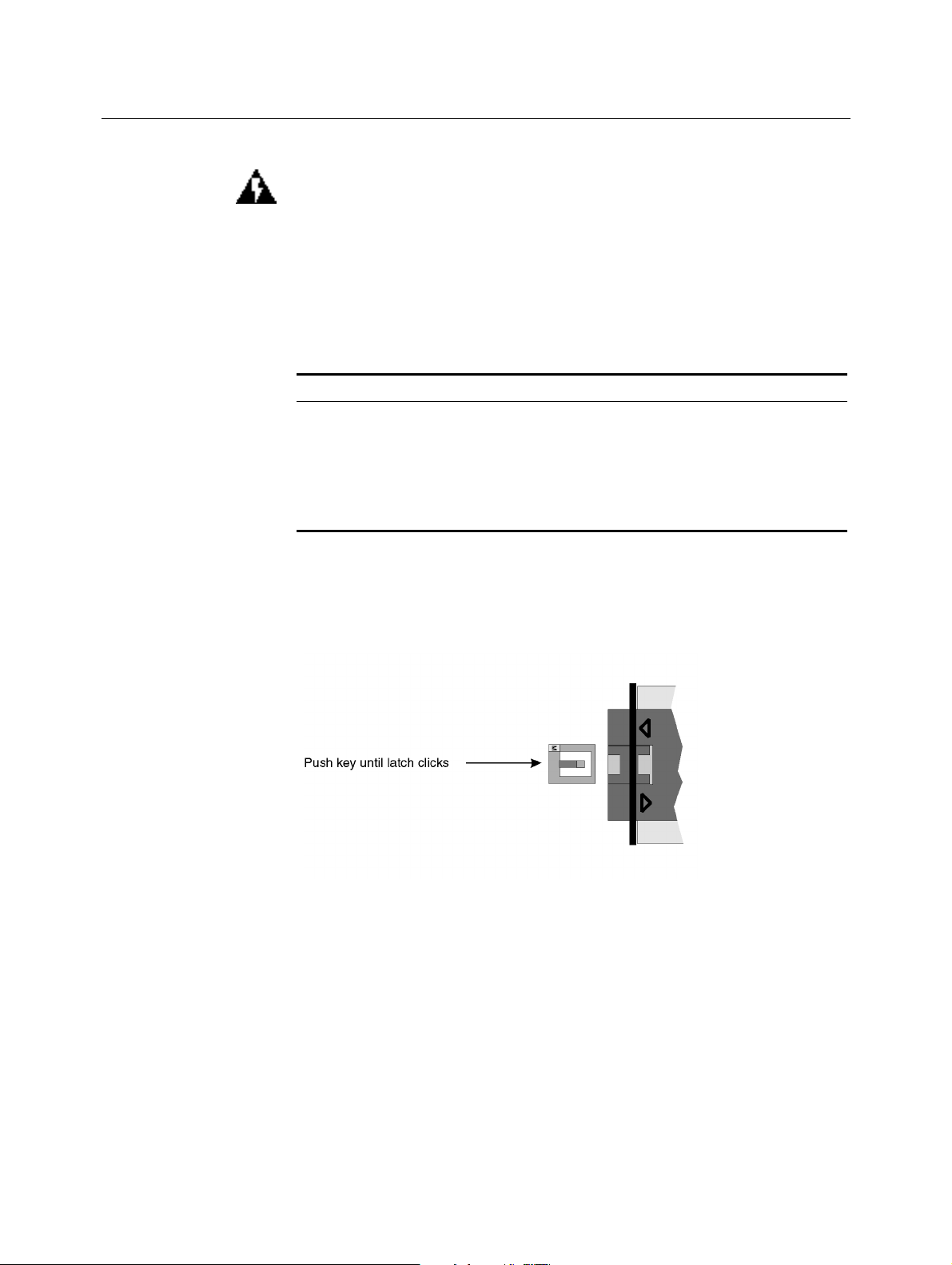
Select the key you want. With the key letter upmost, push the key into the
key way in the case of the launcher (see Figure 1) until the latches click
into place.
Figure 1
Inserting a key
To remove a key, you need to lift the inner bar and depress the center lug
to disengage them before withdrawing the key (see Figure 2). Do NOT use
excessive force!
Page 3

Figure 2 Removing a key
You may find an alternative type of key used. In that event, place the
keyed lug, letter upmost, into the cut-out in the case and lay the key down
with the slots towards the edge connector of the module. Push gently,
down and towards the front of the unit, to engage the latch.
To change a key, insert the tip of a fine screwdriver or similar into the small
slot of the fitted key and press away from the edge, lifting up carefully.
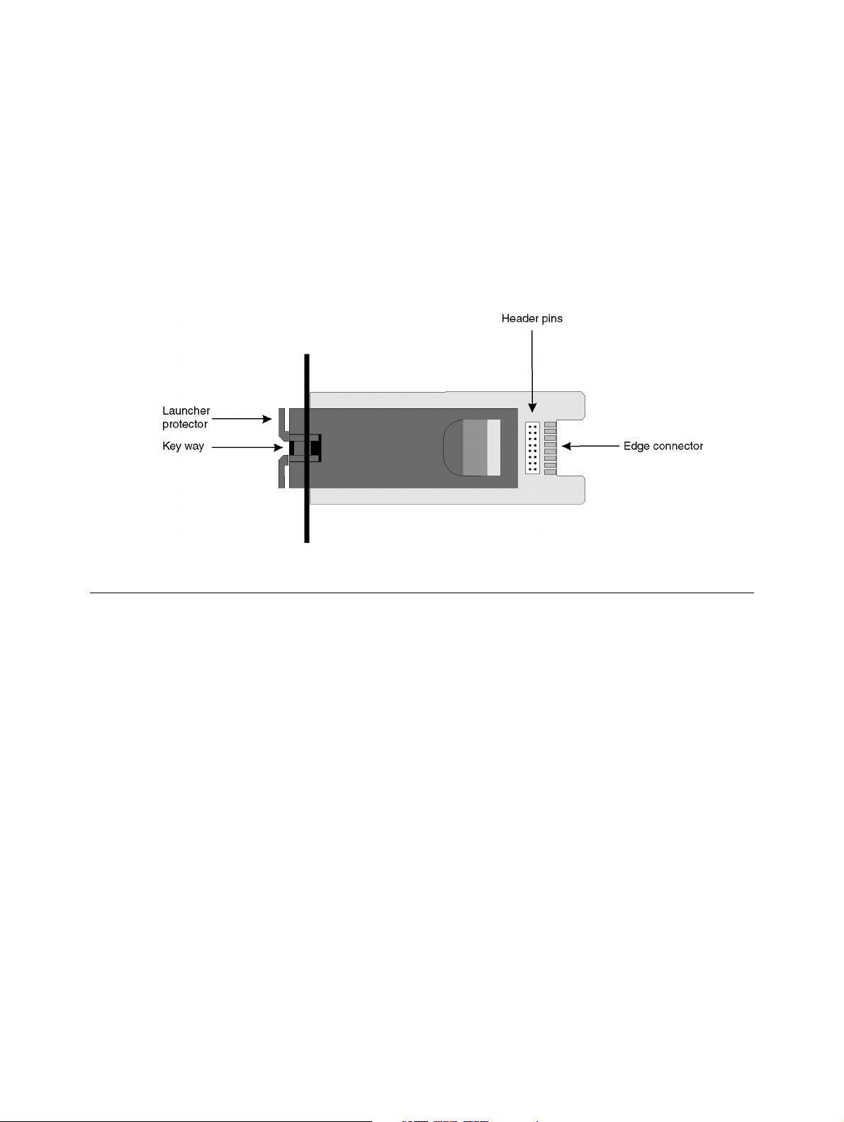
Module-to-Host
Connections
Installing on an
MSH Module
A 16-pin header and a 16-way edge connector are mounted on the FDDI
MIC Media Module for connection to an MSH LinkSwitch Module or a FMS
II LinkSwitch Hub.
Before you install the FDDI MIC Media Module, you must remove the MSH
Module from the network and all power sources. See the relevant MSH
Module User Guide.
Remove the blanking plate from the module which is to receive the FDDI
1
MIC Media Module. The relevant manual will tell you where to find the
plate.
Keep the blanking plate in a safe place so that it can be replaced if the
2
FDDI MIC Media Module is removed.
Place the MSH module on a flat surface with the 16-way socket facing up.
3
Hold the FDDI MIC Media Module by the mounting panel and board edge
4
with the header pins facing down. Pass the board of the FDDI MIC Media
Module through the cut-out in the front panel.
Align the socket on the card with the pins on the FDDI MIC Media Module
5
and push down firmly to connect.
Fix the mounting panel of the FDDI MIC Media Module to the module
6
panel using the two screws from the blanking plate.
Re-install the MSH module into its chassis.
7
Page 4

Installing in a
LinkSwitch Hub
Remove the blanking plate from the hub which is to receive the FDDI MIC
Media Module. The relevant manual will tell you where to find the plate.
Keep the blanking plate in a safe place so that it can be replaced if the
1
FDDI MIC Media Module is removed.
Holding the mounting panel, insert the edge connector end of the FDDI
2
MIC Media Module, with the header pins side down, into the rear of the
hub.
Slide the FDDI MIC Media Module in carefully to engage in the slot and
3
push it fully home.
Fix the mounting panel of the FDDI MIC Media Module to the hub using
4
the two screws from the blanking plate.
Connection to the
FDDI Network
Remove the launcher-protecting device from the MIC connector. Either of
the two types of protector shown Figure 3 and Figure 4 may be
encountered.
Figure 3
Type A protector
Figure 4
Connect the MIC connector to the FDDI MIC Media Module's connector.
Push firmly home.
WARNING:
a tissue moistened with ethanol if necessary.
Type B protector
Take care to keep the ends of the connectors clean. Wipe with
Page 5

Operation Power up the chassis or hub. The FDDI MIC Media Module will operate
correctly once power is applied.
Optical Safety
Under most normal viewing conditions there is no eye hazard from the Tx
launcher LED. It is recommended however, that the LED is not viewed
through any magnifying device, whilst powered on.
Media Module
Fails to Operate
If the FDDI MIC Media Module powers up but no communication is
possible, check that:
■ The remote unit is powered on.
■ The fiber cable is continuous.
The connectors are clean.
■
■ If keys not fitted, the orientation of the MIC connectors is correct.
If these checks fail to cure the problem, refer to the supplier of your 3Com
FDDI MIC Media Module for further advice.
Standards The 3Com FDDI MIC Media Module has been designed to comply with the
following standards:
Functional: ANSI X3T9.5
Safety: UL 1950, EN 60950, CSA 22.2 #950, ECMA 97
R.F.I. FCC part 15 (Class A), Vfg 243 `B', EN55022 A, EC
801 parts 2, 3, 4 & 5
Environmental: IEC 68
 Loading...