

3Com 3C1670500A, 3C1671600A Installation Manual
OfficeConnect
®
Gigabit Switch 5 (3C1670500A)
Gigabit Switch 8 (3C1670800A)
Gigabit Switch 16 (3C1671600)
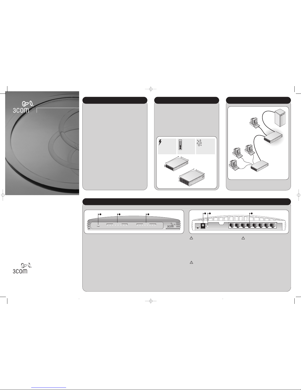
ABOUT YOUR SWITCH
1 2 3
OfficeConnect Gigabit Switch 8
3C1670800A
On = Full
Port Status
Blue = 1000M Green = 100M Yellow = 10M Flash = Activity
1 2 3 4 5 6 7 8 1 2 3 4 5 6 7 8
Duplex
4 5 6
8 1
OK
10-30VDC
1A MAX
WARNING: RJ-45 ports.
These are shielded RJ-45 data sockets. They cannot be
used as standard traditional telephone sockets, or to
connect the unit to a traditional PBX or public telephone
network. Only connect RJ-45 data connectors, network
telephony systems, or network telephones to these
sockets.
Either shielded or unshielded data cables with shielded or
unshielded jacks can be connected to these data sockets.
VORSICHT: RJ-45-Portes.
Diese Portes sind geschützte Datensteckdosen. Sie dürfen
weder wie normale traditionelle Telefonsteckdosen noch
für die Verbindung der Einheit mit einem traditionellenm
privatenm oder öffentlichenm Telefonnetzwerk gebraucht
werden. Nur RJ-45- Datenansclußhlüsse,
Telefonnetzsysteme oder Netztelefone an diese
Steckdosen anschließen.
Entweder geschützte oder ungeschützte Buchsen dürfen
an diese Datensteckdosen angeschlossen werden.
AVERTISSEMENT : Prises RJ-45 blindées.
Ces prises ne peuvent servir comme prises téléphone
standard et ne permettent pas la connexion de l'appareil
à un système PBX ni à un réseau téléphonique public. N'y
branchez que des prises RJ-45 mâles adaptées, ou des
systèmes de réseaux téléphoniques. Il est possible d'y
brancher des câbles blindés ou non comportant des prises
de type Jack (blindées ou non).
1 Power LED
Green
Indicates that the Switch is powered on. If the LED is
off, but the Power Adapter OK LED is lit, there may be
a problem with the Switch’s internal power supply.
Refer to Problem Solving.
2 Five/Eight/Sixteen Port Status LEDs
Blue (1000 Mbps link) / Green (100 Mbps link) /
Yellow (10Mbps link)
If the LED is on, the link between the port and the next
piece of equipment is OK. If the LED is flashing, the
link is OK and data is being transmitted or received. If
the LED is off, nothing is connected or the connected
device is turned off, or there is a problem with the
connection (refer to the Problem Solving section).
3 Duplex LEDs
Yellow (10/100/1000 Mbps, full duplex) /
Off (10/100 Mbps, half duplex)
4 Power Adapter Socket
Only use the power adapter that is supplied with the
Switch.
5 Power Adapter OK LED
Green
Indicates that the power adapter is supplying power to
the Switch. If the LED is off, there may be a problem
with the power adapter or adapter cable (refer to
Problem Solving).
6 10BASE-T/100BASE-TX/1000BASE-T Ports
Use suitable TP cable with RJ-45 connectors. You can
connect your Switch to a workstation, or any other
piece of equipment that has 10BASE-T/100BASE-TX/
1000BASE-T connectivity.
Each port is capable of autosensing for 10 Mbps,
100 Mbps or 1000 Mbps operation.
All ports have an automatic MDI/MDIX feature, which
means either straight-through or crossover cable can
be used to connect to any port.
OfficeConnect Gigabit Switch - Front OfficeConnect Gigabit Switch - Rear
Installation Guide
About This Guide:
Thank you for purchasing the OfficeConnect Gigabit Switch. This high
quality, Gigabit Ethernet Switch is an easy, efficient way of creating a
network or expanding an existing network. The Switch’s Gigabit ports
provide support for bandwidth intensive applications, and allow highspeed connections to servers, and to the rest of the network. An example
configuration is shown in Figure 1.
The Switch is compact and attractively designed for desktop use. It can be
stacked with other units in the OfficeConnect family, which include
Cable/DSL gateways, wireless devices, Fast Ethernet and Gigabit Ethernet
switches. The OfficeConnect family is a fully integrated system, enabling
you to share computer resources, and take advantage of new technologies
as your network grows.
Your Package Contains:
• OfficeConnect Switch
• Power adapter for use with the Switch
• Stacking clip
• Four rubber feet
• This Installation Guide
• Support and Safety Information sheet
• Warranty flyer
About This Guide
This guide will use the term Switch when referring to the OfficeConnect
Gigabit Switch.
INTRODUCTION
CONFIGURATION
Dimensions and Operating Conditions
* Refer to Regulatory Notices in the Support and Safety Information sheet.
†
Category 5 (or better) screened cables must be used to ensure compliance with the Class B
requirements of the above standards. The use of unscreened cables complies with the Class A
requirements.
Gigabit Switch 5
6VA, 20.8 BTU/hr
power requirement
Gigabit Switch 8
8VA, 27.7 BTU/hr
power requirement
Gigabit Switch 16
22.5VA, 77.9 BTU/hr
power requirement
0 to 40ºC
(32 to 105ºF)
operating
temperature
0 to 95%
(non-condensing)
humidity
Weight:
Gigabit Switch 5: 1.0 Kg (2.2 lb)
Gigabit Switch 8: 1.0 Kg (2.2 lb)
Weight:
Gigabit Switch 16: 1.5 Kg (3.3lbs)
Depth:
185.4 mm (7.3 in.)
Height:
54.6 mm (2.1 in.)
Width:
228 mm (9.12 in.)
Depth:
135.4 mm (5.33 in.)
Height:
35.35 mm
(1.36 in.)
Width:
225 mm (8.08 in.)
O
n
= F
u
l
l
P
o
r
t
S
t
a
t
u
s
1
2
3
4
5
6
7
8
1
2
3
4
5
6
7
8
D
u
p
l
e
x
P
or
t
S
ta
t
us
1
2
3
4
5
6
7
8
1
2
3
4
5
6
7
8
D
up
l
ex
O
n
=
F
u
l
l
1
2
3
4
5
6
7
8
9
1
0
1
1
1
2
1
3
14
15
1
6
DIMENSIONS AND STANDARDS
Standards
Functional: ISO 8802/3, IEEE 802.3, 802.3u
Safety: UL 60950-1, EN 60950-1, CSA 22.2 #60950-1, IEC60950-1
EMC
†
: EN 55022 Class B, EN 55024, FCC Part 15 Class B*
ICES-003 Class B
Environmental: EN 60068 (IEC 68)
OfficeConnect Switch 8
with Gigabit Uplink
OfficeConnect
Gigabit Switch
Server
Workstation requiring
High Bandwidth Connection
10/100 Mbps Connections
1000 Mbps Connections
Po
r
t
S
t
a
t
u
s
B
l
u
e
=
1
0
0
0
M
G
r
e
e
n
=
1
0
0
M
Y
e
l
l
o
w
=
1
0
M
F
l
a
s
h
=
A
c
t
i
v
i
t
y
O
n
=
F
u
l
l
G
b
E
1
2
3
4
5
6
7
8
G
b
E
1
2
3
4
5
6
7
8
Off
iceConnect
Switch 8 with Gig
abit Uplink
3
C
1
6
7
0
1
0
8
D
up
lex
P
o
r
t Sta
tu
s
B
lu
e
=
1
00
0
M
G
ree
n
=
10
0
M
Yello
w
=
1
0M
Fla
sh
=
Ac
t
iv
it
y
1
2
3 4
5 6 7 8
1
2 3
4 5
6 7
8
Figure 1 Network showing sample configuration with Gigabit Switch.
3Com Corporation, Corporate Headquarters, 350 Campus Drive, Marlborough, MA 01752-3064
Copyright © 2005 3Com Corporation. All rights reserved. 3Com, the 3Com logo, and
OfficeConnect are registered trademarks of 3Com Corporation.
Microsoft, MS-DOS and Windows are registered trademarks of Micorsoft Corporation.
All other company and product names may be trademarks of their respective companies.
Part No: DIA1670-5AAA04 Published: May 2005
DIA1670-5AAA04.qxd 23/5/05 12:15 pm Page 1
Twisted Pair (TP) Cables
Cables can be shielded (screened) or unshielded. Cables must be Category
5 or above. 3Com recommends Category 5E cable for Gigabit connections.
The maximum length you can use is 100 m (328 ft).
Twisted Pair (TP) cable is very easy to use. To connect a TP cable, simply
slot the connector into the relevant RJ-45 Port. When a connector is fully
in, its latch locks into place. To disconnect the cable, push the connector’s
latch in and remove it.
When one end of a TP cable is connected to the Switch and the other end
is connected to the network interface card of a workstation or other
device, the Switch will automatically detect whether a straight-through or
crossover cable is being used and will compensate if required. The units
will then autonegotiate to determine the fastest possible link speed
between them. This may take a few seconds and the outcome will be
reflected in the LEDs on the front of the Switch.
If the equipment connected to the Switch does not support autonegotiation
or it has been disabled, it must be configured to operate in half duplex mode.
Expanding Your Network
You can increase the number of workstations and other devices that can
connect to your network by adding OfficeConnect gateways and switches.
You can connect a 10BASE-T, 100BASE-TX or 1000BASE-T OfficeConnect
unit to each port of the Switch.
The Switch has automatic MDI/MDIX functionality, and therefore does not
require the Uplink/Normal switch associated with some OfficeConnect
products. Simply plug in the cable, and the Switch will automatically detect
which wiring practice has been followed, and will compensate accordingly.
Checking Unit Connections
When you have connected all your units, power on the units and the
Switch. The Port Status LEDs for the ports you have used should be lit. If
they are not, check your connections.
3
CONNECTING WORKSTATIONS
Switching
When a network of repeater hubs is in operation, any information that is sent
by the workstation is passed around the whole network (regardless of the
destination of the information). This can result in a lot of unnecessary traffic that
can slow the network down. The Switch solves this problem because it "listens"
to the network and automatically learns what workstations can be reached
through its ports. It can then selectively pass on any information by transmitting
the traffic from the relevant port only. This operation is called "switching".
The Switch effectively divides up your network, localizing the network traffic and
passing on traffic as necessary. If you have any high performance workstations
that require a lot of bandwidth, connect them directly to the Switch.
Traffic Prioritization
The Switch has a built in feature to aid network performance at times of
excessive load. It is called Priority Queuing. When a packet is received, the Switch
will examine it to see if it has been priority encoded. If it has, the Switch will then
read the priority level and determine whether it should be directed through the
normal or high priority channel. This feature can be useful during excessive
loads, for example, when one type of traffic may require priority over another.
Connecting 10BASE-T/100BASE-TX/1000BASE-T Networks
The ports can each be connected to a 10BASE-T/100BASE-TX/1000BASE-T
network. If you have various connection speeds in your network, you can join
them together using the Switch allowing all your workstations to
communicate. For example, by connecting one of the ports to a server, all the
workstations connected to the server can communicate with devices connected
to the Switch, significantly increasing the size of your network.
Alternatively, if for example you use a 10BASE-T/100BASE-TX network and
want to improve network performance by introducing 1000BASE-T technology,
the Switch protects the investment in your existing workstations because it
maintains 10BASE-T/100BASE-TX connections to them.
The Switch has been designed to aid you when detecting and solving possible
problems with your network. These problems are rarely serious; the cause is
usually a disconnected or damaged cable, or incorrect configuration. If this
section does not solve your problem, contact your supplier for information on
what to do next.
Perform these actions first:
• Ensure all network equipment is powered on.
• Power each piece of network equipment off, wait about five seconds and
then power each one on.
CAUTION: Do not power the Switch off and then immediately on. Wait
about five seconds between power cycles.
Check the following symptoms and solutions:
Power Status LED or Power Adapter OK LED not lit. Refer to the following table.
Power Adapter OK LED Power Status LED Problem and Action
On On All functioning correctly
On Off The internal power circuit has
failed.
Contact 3Com Technical Support
for a replacement Switch.
Off Off The power adapter or power
adapter connection is faulty.
Refer to "Replacement Power
Adapters" below.
Replacement Power Adapters
If both the Power Adapter OK LED and Power Status LED are off, check your
power adapter connection. If there is still no power, contact 3Com Technical
Support and ask for a replacement power adapter. Please quote the power
adapter part number, shown on the OfficeConnect power adapter you are
currently using.
Alternatively, quote the part number for your region:
3C number Region
3C16740A US United States
3C16741A UK United Kingdom
3C16742A ME Mainland Europe
3C16743A JPN Japan
3C16744A AA Australasia
3C16745A SA South Africa
3C16747A KR South Korea
3C16748A RA Argentina
3C16757 Gigabit Switch 16 only Worldwide Use
Only use the power adapter supplied with the Switch or a replacement
OfficeConnect power adapter. Do not use any other power adapter.
Port Status LED not lit for a port that has a TP cable connected. After
connection, it may take several seconds for the Port Status LEDs to illuminate.
The Port Status LED should turn Blue, Green or Yellow for each port that is
connected, depending on connection speed. The Duplex LED may or may not
illuminate. Please refer to ‘About Your Switch’ for a full description of the LEDs.
If the Port Status LED is not lit after several seconds, ensure that the
connected device is powered on, that the TP cable is not damaged and that it
is correctly inserted at both ends.
You may find that a TP cable works when connected to the Switch, but that it
does not if disconnected from the Switch and connected to another device.
This may be because the other device does not have the automatic MDI/MDIX
feature.
The Port Status LED is lit but the network performance of the switch
is poor. The switch supports full-duplex autonegotiation. If the connected
device does not support autonegotiation, ensure it is configured for half
duplex operation only.
5
PROBLEM SOLVING
Unit Connections
To connect OfficeConnect units (such as gateways or other switches) to
your Switch you need:
• One suitable Twisted Pair (TP) cable for each unit
3Com recommends Category 5E cable for Gigabit connections.
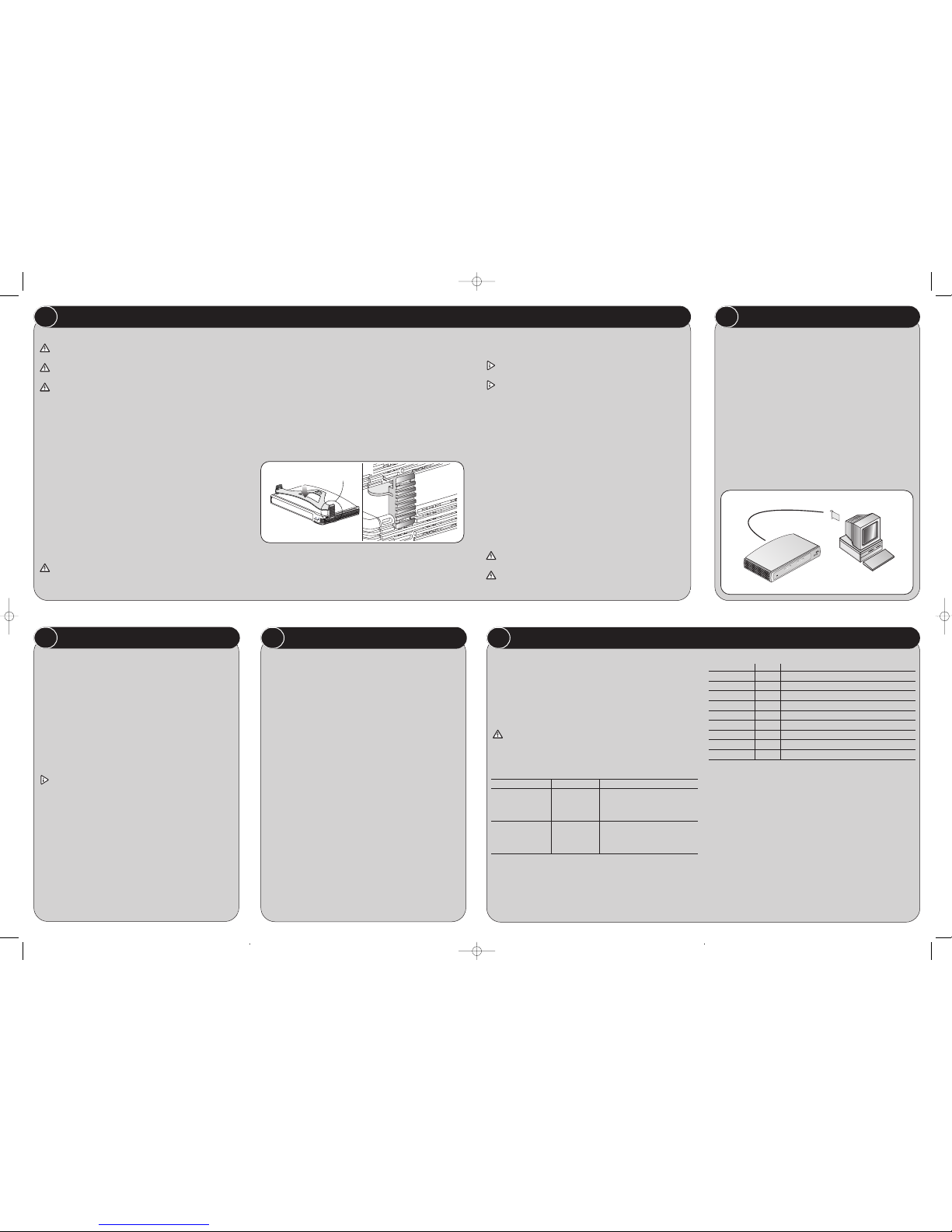
Workstation Connections
To connect workstations or other equipment (such as servers) directly to
your Switch, you need:
1 One adapter card for each workstation to be connected to a port on
the Switch. The adapter card must be capable of communicating at the
required connection speed. For example, if you want to use a Gigabit
connection, you must install a 1000BASE-T adapter card. 3Com
produce a range of easy to install 1000BASE-T Network adapter cards.
2 An operating system (for example Netware or Windows
95/98/Me/2000/XP) with network support configured, running on your
workstations.
3 One suitable Twisted Pair cable for each workstation.
2 BEFORE YOU INSTALL YOUR SWITCH
4
HOW YOUR SWITCH CAN BE USED
O
f
f
i
c
e
C
o
n
n
e
c
t
G
ig
a
b
it S
w
itc
h 5
3
C
1
6
7
0
5
0
0
A
Yellow = 10/100 Full
Green = 1000 Full
Por
t S
ta
tu
s
G
r
e
e
n
=
1
0
0
M
o
r
1
0
0
0
M
Y
e
l
l
o
w
=
1
0
M
F
l
a
s
h
=
Ac
t
i
v
i
t
y
1
2
3 4 5
1 2
3 4 5
Dup
lex
3
1
2
Figure 3 Workstation connections
Safety Information
WARNING: Please read the ‘Important Safety Information’ section in
the Support and Safety Information sheet before you start.
VORSICHT: Bitte lesen Sie den Abschnitt ‘Wichtige
Sicherheitsinformationen’ sorgfältig durch, bevor Sie das Gerät einschalten.
AVERTISSEMENT:Veuillez lire attentivement la section "Consignes
importantes de sécurité" avant de mettre en route.
When positioning your Switch, ensure:
• It is out of direct sunlight and away from sources of heat.
• Cabling is away from power lines, fluorescent lighting fixtures, and
sources of electrical noise such as radios, transmitters and broadband
amplifiers.
• Water or moisture cannot enter the case of the unit.
• Air flow around the unit and through the vents in the side of the case is
not restricted. 3Com recommends you provide a minimum of 25 mm
(1 in.) clearance.
Using the Rubber Feet
Use the four self-adhesive rubber feet to prevent your Switch from moving
around on your desk, or when stacking with flat top OfficeConnect units.
Only stick the feet to the marked areas at each corner on the underside of
your Switch.
Using a Stacking Clip
Use a stacking clip when stacking your Switch with other curved
OfficeConnect units. The stacking clip allows you to stack units neatly and
securely.
CAUTION: You can stack up to a maximum of four units. Smaller units
must be stacked above larger units.
To fit the clip:
1 Fit the clip across the top of the unit, as shown in Figure 2 (picture 1),
ensuring that the longer sections of the fastening pieces are pointing
downwards.
2 Align the fastening pieces over the slots found on each side of the unit.
3 Push the clip down gently to secure it, ensuring that the fastening pieces
snap into the slots on the unit.
To fit another unit:
1 Rest the second unit on the top of the clip and align it with the front of
the unit below.
2 Press down gently on the unit to secure it onto the clip, ensuring the
fastening pieces fit into the slots on the unit below, as shown in Figure 2
(picture 2).
Wall Mounting
There are two slots on the underside of the Switch that can be used for wall
mounting. The Switch must be mounted with the LEDs facing upwards.
When wall mounting the unit, ensure it is within reach of the power
outlet
When wall mounting the unit, ensure that the rubber feet are not fixed
Mounting Instructions for Cement Walls
1 Make two holes 150 mm (5.9 in.) apart and insert two nylon or similar
screw anchors that are suitable for the wall construction.
2 Fix two suitable screws into the anchors, leaving their heads 3 mm
(0.12 in.) clear of the wall surface. The screws should be at least 30 mm
(1.2 in.) long,
3 Remove any connections in the Switch and locate it over the screw heads.
When in line, gently push the Switch on to the wall and move it
downwards to secure.
Mounting Instructions for Wood Walls
1 Make two holes 150 mm (5.9 in.) apart.
2 Fix two suitable screws directly into the wall, leaving their heads 3 mm
(0.12 in.) clear of the wall surface. The screws should be at least 20 mm
(0.75 in.) long,
3 Remove any connections in the Switch and locate it over the screw heads.
When in line, gently push the Switch on to the wall and move it
downwards to secure.
CAUTION: When making connections, be careful not to push the
Switch up and off the wall.
CAUTION: Only wall mount single units, do not wall mount
stacked units.
1
POSITIONING YOUR SWITCH
Figure 2 Stacking Your Units together
1
2
Fastening
Piece
Fastening
Piece
DIA1670-5AAA04.qxd 23/5/05 12:15 pm Page 2
 Loading...