

Page 1

SuperStack® II
®
Switch 3800
User Guide
http://www.3com.com/
Part No. DUA1691-0AAA01
100004-00 Rev. 01
Published April 1998
Page 2

3Com Corporation
5400 Bayfront Plaza
Santa Clara, California
95052-8145
Copyright ©
reproduced in any form or by any means or used to make any derivative work (such as translation,
transformation, or adaptation) without permission from 3Com Technologies.
3Com Technologies reserves the right to revise this documentation and to make changes in content from
time to time without obligation on the part of 3Com Technologies to provide notification of such revision
or change.
3Com Technologies provides this documentation without warranty of any kind, either implied or expressed,
including, but not limited to, the implied warranties of merchantability and fitness for a particular purpose.
3Com may make improvements or changes in the product(s) and/or the program(s) described in this
documentation at any time.
UNITED STATES GOVERNMENT LEGENDS:
If you are a United States government agency, then this documentation and the software described herein
are provided to you subject to the following restricted rights:
For units of the Department of Defense:
Restricted Rights Legend:
forth in subparagraph (c) (1) (ii) for Restricted Rights in Technical Data and Computer Software Clause at 48
C.F.R. 52.227-7013. 3Com Technologies, c/o 3Com Limited, 3Com Centre, Boundary Way, Hemel
Hempstead, Herts, HP2 7YU, United Kingdom.
For civilian agencies:
Restricted Rights Legend:
(a) through (d) of the Commercial Computer Software - Restricted Rights Clause at 48 C.F.R. 52.227-19 and
the limitations set forth in 3Com Corporation’s standard commercial agreement for the software.
Unpublished rights reserved under the copyright laws of the United States.
If there is any software on removable media described in this documentation, it is furnished under a license
agreement included with the product as a separate document, in the hard copy documentation, or on the
removable media in a directory file named LICENSE.TXT. If you are unable to locate a copy, please contact
3Com and a copy will be provided to you.
Unless otherwise indicated, 3Com registered trademarks are registered in the United States and may or may
not be registered in other countries.
3Com, EtherLink, SuperStack, and Transcend are registered trademarks of 3Com Corporation and 3TECH is
a trademark of 3Com Corporation. 3ComFacts is a service mark of 3Com Corporation.
CompuServe is a registered trademark of CompuServe, Inc. Other brand and product names may be
registered trademarks or trademarks of their respective holders.
3Com Corporation, 1998.
Use, duplication, or disclosure by the Government is subject to restrictions as set
Use, reproduction, or disclosure is subject to restrictions set forth in subparagraph
All rights reserved. No part of this documentation may be
Electromagnetic
Compatibility
ii
FCC Statement
This equipment has been tested with a class A computing device and has been found to comply with part
15 of FCC Rules. Operation in a residential area may cause unacceptable interference to radio and TV
receptions, requiring the operator to take whatever steps are necessary to correct the interference.
CSA Statement
This Class A digital apparatus meets all requirements of the Canadian interference-Causing Equipment
Regulations.
Cet appareil numérique de la classe A respecte toutes les exigences du Règlement sur le matériel brouilleur
du Canada.
Page 3
VCCI Statement
Information To The User
If this equipment does cause interference to radio or television reception, which can be determined by
turning the equipment off and on, the user is encouraged to try to correct the interference by one or more
of the following measures:
■
Reorient the receiving antenna.
Relocate the equipment with respect to the receiver.
■
■
Move the equipment away from the receiver.
■
Plug the equipment into a different outlet so that equipment and receiver are on different branch
circuits.
If necessary, the user should consult the dealer or an experienced radio/television technician for additional
suggestions. The user may find the following booklet prepared by the Federal Communications Commission
helpful:
How to Identify and Resolve Radio-TV Interference Problems
This booklet is available from the U.S. Government Printing Office, Washington, DC 20402, Stock No.
004-000-00345-4.
In order to meet FCC emissions limits, this equipment must be used only with cables which comply with
IEEE 802.3.
iii
Page 4

iv
Page 5

C
ONTENTS
A
BOUT THIS GUIDE
Introduction 1
Terminology 1
Finding Information in This Guide 2
Conventions 3
Command Syntax Symbols 4
Line-Editing Commands 5
Related Publications 5
S
1
WITCH
About the Switch 3800 1-1
Summary of Features 1-1
Network Configuration Example 1-5
Switch 3800 Front View 1-7
Switch 3800 Rear View 1-9
Factory Defaults 1-10
3800 O
Port Connections 1-3
Full-duplex 1-3
Port Redundancy 1-3
Load Sharing 1-4
Switch Operation 1-4
Virtual LANs (VLANs) 1-4
Priority Access Control Enabled (PACE) 1-5
Spanning Tree Protocol (STP) 1-5
IP Unicast Routing 1-5
Ports 1-7
LEDs 1-8
Power Socket 1-9
Serial Number 1-9
MAC Address 1-10
Console Port 1-10
VERVIEW
v
Page 6

NSTALLATION AND SETUP
I
2
Following Safety Information 2-1
Determining the Switch 3800 Location 2-1
Configuration Rules for Ethernet 2-2
Installing the Switch 3800 2-2
Rack Mounting 2-2
Free-Standing 2-3
Stacking the Switch and Other Devices 2-4
Connecting Equipment to the Console Port 2-4
Powering-up the Switch 2-6
Checking the Installation 2-6
Power On Self-Test (POST) 2-6
Logging on for the First Time 2-6
3
CCESSING THE SWITCH
A
Security Access Levels 3-1
User Access Level 3-1
Administrator Access Level 3-2
Default Accounts 3-2
Adding a Password to the Default
Creating a Management Account 3-3
Changing Account Passwords 3-3
Viewing Switch Accounts 3-4
Deleting a Switch Account 3-4
Methods of Managing the Switch 3800 3-4
Using the Console Interface 3-5
Using Telnet 3-5
Configuring Switch IP Parameters 3-5
Using a BOOTP Server 3-5
Manually Configuring the IP Settings 3-6
Disconnecting a Telnet Session 3-7
Disabling Telnet Access 3-8
Using SNMP 3-8
Accessing Switch Agents 3-9
Saving Configuration Changes 3-9
Supported MIBs 3-9
Supported Traps 3-9
admin
Account 3-2
vi
Page 7

Configuring SNMP Settings 3-10
Displaying SNMP Settings 3-12
Resetting and Disabling SNMP 3-12
Checking Basic Connectivity 3-12
Ping 3-12
Traceroute 3-13
Configuring Ports 3-13
Enabling and Disabling Ports 3-13
Configuring Autonegotiation 3-14
10/100 port settings 3-14
Gigabit port settings 3-14
Load Sharing 3-15
Configuring Load Sharing 3-15
Verifying the Load Sharing Configuration 3-16
Current Limitations of Load Sharing 3-16
SmartRedundancy 3-17
Port Commands 3-17
4
OMMANDS
C
Understanding the Command Syntax 4-1
Syntax Helper 4-2
Command Completion 4-2
Abbreviated Syntax 4-2
Command Shortcuts 4-2
Numerical Ranges 4-3
Names 4-3
Symbols 4-3
Line-Editing Commands 4-4
Command History Substitution 4-5
Common Commands 4-5
Switch 3800 Commands 4-6
General Switch Commands 4-7
User Account Commands 4-8
Switch Management Commands 4-9
VLAN Commands 4-10
Protocol Commands 4-11
FDB Commands 4-11
vii
Page 8

Port Commands 4-12
PACE Commands 4-13
STP Commands 4-14
Basic IP Commands 4-16
IP ARP Commands 4-17
IP Route Table Commands 4-18
ICMP Commands 4-18
RIP Commands 4-20
Logging Commands 4-22
Configuration and Image Commands 4-23
5
6
IRTUAL
V
Overview of Virtual LANs 5-1
Configuring VLANs on the Switch 3800 5-11
Displaying VLAN Settings 5-13
Deleting and Resetting VLANs 5-15
WITCH FORWARDING DATABASE
S
Overview of the FDB 6-1
LANS (VLANS)
Benefits 5-1
Types of VLANs 5-2
Port-Based VLANs 5-2
Expanding Port-Based VLANs Across Switches 5-4
Tagged VLANs 5-6
Uses of Tagged VLANs 5-6
Assigning a VLAN Tag 5-6
Mixing Port-based and Tagged VLANs 5-8
Protocol-based VLANs 5-8
Predefined Protocol Filters 5-9
Defining Protocol Filters 5-10
VLAN Names 5-10
The Default VLAN 5-11
VLAN Configuration Examples 5-12
FDB Contents 6-1
FDB Entry Types 6-1
PACE Prioritization 6-2
How FDB Entries are Added 6-2
(FDB)
viii
Page 9

Configuring FDB Entries 6-3
FDB Configuration Example 6-3
Displaying FDB Entries 6-3
Removing FDB Entries 6-4
7
PANNING TREE PROTOCOL
S
Overview of the Spanning Tree Protocol 7-1
How STP Works 7-3
Initialization 7-3
Stabilization 7-4
Reconfiguration 7-4
Spanning Tree Domains 7-4
Defaults 7-5
STP Configurations 7-6
STP Configurations to Avoid 7-8
Creating STP Domains 7-9
Enabling STP on the Switch 7-10
Configuring STP 7-10
Configuration Example 7-12
Displaying STP Settings 7-12
Disabling and Resetting STP 7-14
(STP)
IP U
8
NICAST ROUTING
Overview of IP Unicast Routing 8-1
Router Interfaces 8-1
Populating the Routing Table 8-2
Dynamic Routes 8-3
Static Routes 8-3
Multiple Routes 8-3
Configuring IP Unicast Routing 8-4
Verifying the IP Unicast Routing Configuration 8-5
Configuring DHCP/BOOTP Relay 8-5
Verifying the DHCP/BOOTP Relay Configuration 8-5
Routing Configuration Example 8-10
Displaying Router Settings 8-12
Resetting and Disabling Router Settings 8-13
ix
Page 10

TATUS MONITORING AND STATISTICS
S
9
Status Monitoring 9-1
Port Statistics 9-4
Port Errors 9-6
Switch Logging 9-7
Local Logging 9-8
Real-time Display 9-8
Remote Logging 9-9
Logging Commands 9-10
RMON 9-11
About RMON 9-11
About the RMON Groups 9-12
Statistics 9-12
History 9-12
Alarms 9-13
Events 9-13
Benefits of RMON 9-13
Improving Efficiency 9-13
Allowing Proactive Management 9-13
Reducing the Traffic Load 9-13
RMON and the Switch 9-14
RMON Features of the Switch 9-14
About Event Actions 9-15
10
S
OFTWARE UPGRADE AND BOOT OPTIONS
Upgrading the Software 10-1
Rebooting the Switch 10-2
Saving Configuration Changes 10-2
Returning to Factory Defaults 10-3
Boot Option Commands 10-3
A
x
AFETY INFORMATION
S
Important Safety Information A-1
Power A-1
Power Cord A-2
Fuse A-3
Page 11

Fiber Optic Ports A-3
Lithium Battery A-4
L’information de Sécurité Importante A-4
Power A-5
Cordon électrique A-6
Fuse A-6
Ports pour fibres optiques A-7
Batterie au lithium A-7
Wichtige Sicherheitsinformationen A-8
Power A-8
Power Cord A-9
Fuse A-9
Faseroptikanschlüsse - Optische Sicherheit A-10
Lithiumbatterie A-11
B
C
D
ECHNICAL SPECIFICATIONS
T
T
ROUBLESHOOTING
LEDs C-1
Using the Command-Line Interface C-2
VLANs C-4
STP C-5
Routing C-6
ECHNICAL SUPPORT
T
Online Technical Services D-1
World Wide Web Site D-1
3Com Bulletin Board Service D-1
Access by Analog Modem D-1
Access by Digital Modem D-2
3ComFactsSM Automated Fax Service D-2
3ComForum on CompuServe® Online Service D-3
Support from Your Network Supplier D-3
Support from 3Com D-4
Returning Products for Repair D-5
xi
Page 12

G
LOSSARY
I
NDEX
3COM C
ORPORATION LIMITED WARRANTY
xii
Page 13

BOUT
A
About This Guide provides an overview of this guide, describes guide conventions, tells you where to look for specific information and lists other publications that may be useful.
T
HIS
G
UIDE
Introduction This guide provides the required information to install and configure
the SuperStack
This guide is intended for use by network administrators who are
responsible for installing and setting up network equipment. It
assumes a basic working knowledge of:
■ Local Area Networks (LANs)
■ Ethernet concepts
■ Ethernet switching and bridging concepts
■ Simple Network Management Protocol (SNMP)
■ IP Routing
The Release Notes shipped with the Switch 3800 may contain
information that updates or overrides information in this guide. You
should always follow the information in the Release Notes if it is
different from the information given in this guide.
Terminology Throughout this guide, the term Switch 3800 is used to refer to the
SuperStack II Switch 3800.
For definitions of other terms used in this guide, refer to the
“Glossary,” located at the end of the user guide.
®
II Switch 3800 (3C16910).
The terms Forwarding Database and Switch Database are
interchangeable.
Page 14

2 ABOUT THIS GUIDE
Finding Information in This Guide
This table shows where to find specific information in this guide.
Task Location
Learning concepts Chapter 1, “Switch 3800 Overview”
Installing the Switch 3800 Chapter 2, “Installation and Setup”
Appendix A, “Safety Information”
Setting up user accounts Chapter 3, “Accessing The Switch”
Understanding the
Command-Line Interface
Creating a VLAN Chapter 5, “Virtual LANs (VLANs)”
Understanding the Switch
Forwarding Database (FDB)
Configuring Spanning Tree
Protocol parameters
Configuring IP Unicast Routing Chapter 8, “IP Unicast Routing
Monitoring Chapter 9, “Status Monitoring and Statistics”
Saving the Switch configuration Chapter 10, “Software Upgrade and Boot
Upgrading the Switch software Chapter 10, “Software Upgrade and Boot
Technical Specifications Appendix B, “Technical Specifications”
Troubleshooting Appendix C, “Troubleshooting”
Getting technical support Appendix D, “Technical Support”
Identifying terms “Glossary”
Chapter 4, “Commands”
Chapter 6, “Switch Forwarding Database (FDB)”
Chapter 7, “Spanning Tree Protocol (STP)”
Options”
Options”
Page 15
Conventions 3
Conventions Table 1 and Table 2 list conventions that are used throughout this
guide.
Table 1 Notice Icons
Icon Notice Type Alerts you to...
Note Important features or instructions
Caution Risk of personal injury, system damage, or loss
of data
Warning Risk of severe personal injury
Table 2 Text Conventions
Convention Description
Screen displays This typeface represents information as it appears on the
screen.
The words “enter”
and “type”
When you see the word “enter” in this guide, you must
type something, and then press the Return or Enter key. Do
not press the Return or Enter key when an instruction
simply says “type.”
[Key] names Key names appear in text in one of two ways:
■ Referred to by their labels, such as “the Return key” or
“the Escape key”
■ Written with brackets, such as [Return] or [Esc]
If you must press two or more keys simultaneously, the key
names are linked with a plus sign (+). Example:
Press [Ctrl]+[Alt]+[Del].
Words in italicized
type
Words in boldface
Italics emphasize a point or denote new terms at the place
where they are defined in the text.
Bold text denotes key features.
type
Page 16

4 ABOUT THIS GUIDE
Command Syntax Symbols
You may see a variety of symbols shown as part of the command
syntax. These symbols explain how to enter the command, and you do
not type them as part of the command itself. Table 3 summarizes
command syntax symbols.
Table 3 Command Syntax Symbols
Symbol Description
angle brackets < > Enclose a variable or value. You must specify the variable or value. For example, in
square brackets [ ] Enclose a required value or list of required arguments. One or more values or
vertical bar | Separates mutually exclusive items in a list, one of which must be entered. For
braces { } Enclose an optional value or a list of optional arguments. One or more values or
the syntax
config vlan <name> ipaddress <ip_address>
you must supply a VLAN name for <name> and an address for <ip_address> when
entering the command. Do not type the angle brackets.
arguments can be specified. For example, in the syntax
disable vlan [<name> | all]
you must specify either the VLAN name for <name>, or the keyword “all” when
entering the command. Do not type the square brackets.
example, in the syntax
config snmp community [read | write] <string>
you must specify either the read or write community string in the command. Do not
type the vertical bar.
arguments can be specified. For example, in the syntax
show vlan {<name> | all}
you can specify either a particular VLAN or the keyword “all.” If you do not specify
an argument, the command will show all VLANs. Do not type the braces.
Page 17

Line-Editing Commands 5
Line-Editing Commands
Table 4 describes the line-editing commands available using the
command-line interface.
Table 4 Line-Editing Commands
Command Description
Backspace Deletes character to the left of cursor and shifts remainder of line to left.
Delete or [Ctrl] + D Deletes character under cursor and shifts remainder of line to left.
[Ctrl] + K Deletes characters from under cursor to the end of the line.
Insert Toggles on and off. When toggled on, inserts text and pushes previous text to right.
Left Arrow Moves cursor to left.
Right Arrow Moves cursor to right.
Home or [Ctrl]+A Moves cursor to first character in line.
End or [Ctrl]+E Moves cursor to last character in line.
[Ctrl]+L Clears the screen and moves the cursor to the beginning of the line.
Up Arrow Displays the previous command in the command history buffer, and places cursor at
Down Arrow Displays the next command in the command history buffer, and places cursor at end
end of command.
of command.
The command syntax is explained in Chapter 4.
Related Publications
The Switch 3800 documentation set includes the following:
■ SuperStack II Switch 3800 Quick Reference Guide.
Part Number DQA1691-OAAA01.
■ SuperStack II Switch 3800 Quick Installation Guide.
Part Number DIA1691-OAAA01.
■ SuperStack II Switch 3800 Release Note.
Part Number DNA1691-OAAA01.
3Com’s home page can be found at the following web site:
■ http://www.3com.com/
Page 18

6 ABOUT THIS GUIDE
Page 19

1
SWITCH 3800 OVERVIEW
This chapter describes the following:
■ Switch 3800 features
■ How to use the Switch 3800 in your network configuration
■ Switch 3800 front view
■ Switch 3800 rear view
■ Factory default settings
About the
Switch 3800
Summary of Features
Network managers are currently faced with the challenge of creating
networks that can provide high-speed and high performance to serve
the needs of today’s network users.
Part of the 3Com SuperStack
®
II range of products, the Switch 3800
provides switching and IP Routing between multiple
10BASE-T/100BASE-TX ports and one Gigabit Ethernet port.
The Switch 3800 has the following features:
■ 24 autosensing 10BASE-T/100BASE-TX ports, one Gigabit Ethernet
port, and one redundant Gigabit Ethernet port
■ Support for 12,000 addresses in the Switch forwarding database
■ Fully nonblocking operation
■ All ports transmit and receive packets at wire speed
■ Full-duplex operation
■ 2Mb packet memory
Page 20

1-2 CHAPTER 1: SWITCH 3800 OVERVIEW
■ Virtual LANs (VLANs)
■ Support for 64 VLANs on a single Switch 3800
■ Support for IEEE 802.1Q tagging
■ Controls traffic (including broadcasts)
■ Provides extra security
■ Protocol-sensitive filtering for VLANs
■ Recognition of the Priority Access Control Enabled (PACE) bit set by
3Com Etherlink
■ Responds to 802.3x flow-control messages
■ Autonegotiation to IEEE 802.3z for Gigabit Ethernet
■ Load sharing
■ Spanning Tree Protocol (IEEE 802.1d)
■ Multiple spanning trees (64)
■ Wire speed Internet Protocol (IP) via Routing Information Protocol
®
adapters and the other devices that support PACE
(RIP) version 1 and RIP version 2
■ Wire speed Internet Protocol (IP) unicast routing
■ 3Com’s SuperStack
■ Integrated network management
■ 19-inch rack or free-standing mounting
■ Agent support
■ Simple Network Management Protocol (SNMP)
■ Remote Monitoring (RMON) groups 1 to 4 — statistics, history,
®
II architecture
alarms, and events
■ Repeater and Bridge Management Information Base (MIB)
■ Easy software upgrades
■ BOOTP for automatic Internet Protocol (IP) address configuration
■ Local management
Page 21
Summary of Features 1-3
Port Connections The Switch 3800 has 24 autosensing 10BASE-T/100BASE-TX ports with
standard RJ-45 connectors, and supports one Gigabit Ethernet port,
and one redundant Gigabit Ethernet port with standard Gigabit
Interface Connectors (GBICs). You must have a 3Com-approved GBIC
module (such as 3C16911) inserted to make use of these ports. You
can connect other Gigabit Ethernet devices (such as 10/100 Switches
that have Gigabit Ethernet modules) to the Switch 3800. You can also
connect Switch 3800 devices to each other.
10BASE-T/100BASE-TX ports are configured as MDIX (crossover). A
crossover cable will typically be needed to connect these ports to
another 3Com Switch.
Full-duplex The Switch 3800 provides full-duplex support for all ports. Full-duplex
allows frames to be transmitted and received simultaneously and, in
effect, doubles the bandwidth available on a link. All 10/100 Mbps
ports on the Switch 3800 autonegotiate for half- or full-duplex
operation.
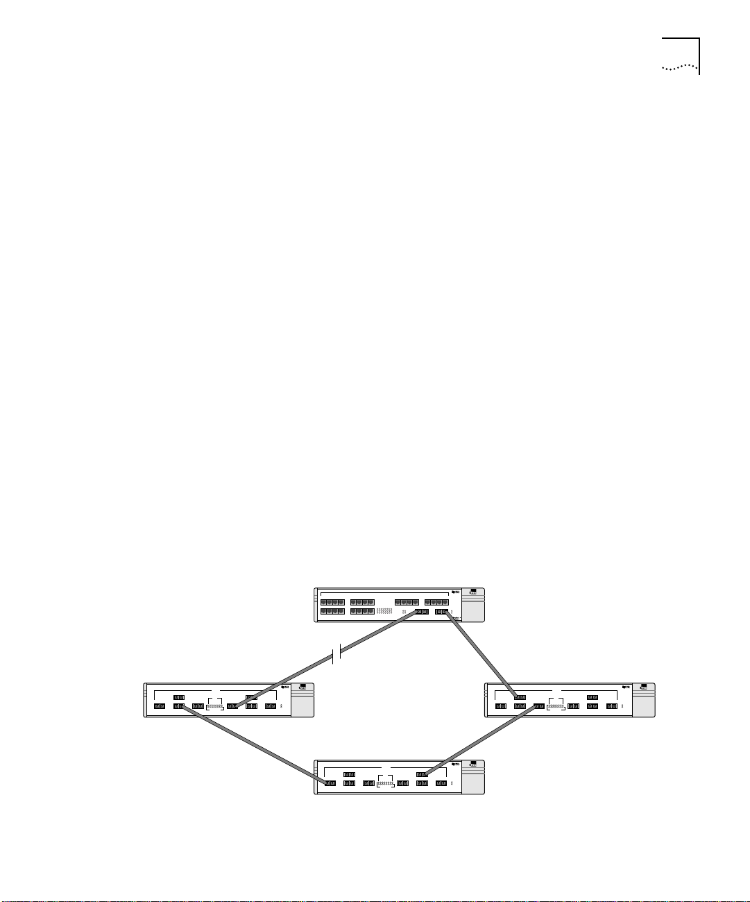
Port Redundancy The Switch 3800 has an optional redundant Gigabit Ethernet port to
provide resilient links. Using the redundant port (the redundant port is
labeled 25-Standby), you can dual-home to one or two Switches.
Figure 1-1 illustrates a Switch 3800 dual-homed to two different
Switches.
Dual-homed
Standby
Figure 1-1 Dual-homing configuration
Main
Page 22

1-4 CHAPTER 1: SWITCH 3800 OVERVIEW
In the event that the active main port fails or loses link status, the
standby port is automatically activated. When the main port resumes
operation, the standby port becomes inactive. This feature can be
disabled.
Load Sharing Load sharing with Switch 3800 Switches allows the user to increase
bandwidth and resilience between Switches by using a group of ports
to carry traffic in parallel between Switches. The sharing algorithm
allows the Switch to use multiple ports as a single logical port. For
example, Virtual LANs (VLANs) see the load-sharing group as a single
virtual port. The algorithm also guarantees packet sequencing between
clients.
For information on load sharing, refer to Chapter 3.
Switch Operation The Switch 3800 uses the same algorithm as a conventional 802.1d
bridge for filtering, forwarding, and learning packets.
Virtual LANs (VLANs)
The Switch 3800 has a Virtual LAN (VLAN) feature that allows you to
build your network segments without being restricted by physical
connections. A VLAN is a group of location- and topology-independent
devices that communicate as if they are on the same physical Local
Area Network (LAN). Implementing VLANs on your network has the
following three advantages:
■ It eases the change and movement of devices on networks. If a
device in VLAN marketing is moved to a port in another part of the
network, all you must do is specify that the new port belongs to
VLAN marketing.
■ It helps to control broadcast traffic. If a device in VLAN marketing
transmits a broadcast frame, only VLAN marketing devices receive
the frame.
■ It provides extra security. Devices in VLAN marketing can only
communicate with devices on VLAN sales using a device that
provides routing services.
For more information on VLANs, refer to Chapter 5.
Page 23
Network Configuration Example 1-5
Priority Access Control Enabled (PACE)
The Switch recognizes the PACE bit set by 3Com Etherlink
®
adapters
and other devices supporting PACE. When enabled, traffic with these
bits receives priority service from the Switch.
Spanning Tree Protocol
(STP)
The Switch 3800 supports the IEEE 802.1d Spanning Tree Protocol
(STP), which is a bridge-based mechanism for providing fault tolerance
on networks. STP allows you to implement parallel paths for network
traffic, and ensure the following:
■ Redundant paths are disabled when the main paths are operational.
■ Redundant paths are enabled if the main traffic paths fail.
For more information on STP, refer to Chapter 7.
IP Unicast Routing
The Switch 3800 can route IP traffic between the VLANs configured as
virtual router interfaces. Both dynamic and static IP routes are
maintained in the routing table. RIP version 1 and RIP version 2 are
supported.
For more information on IP unicast routing, refer to Chapter 8.
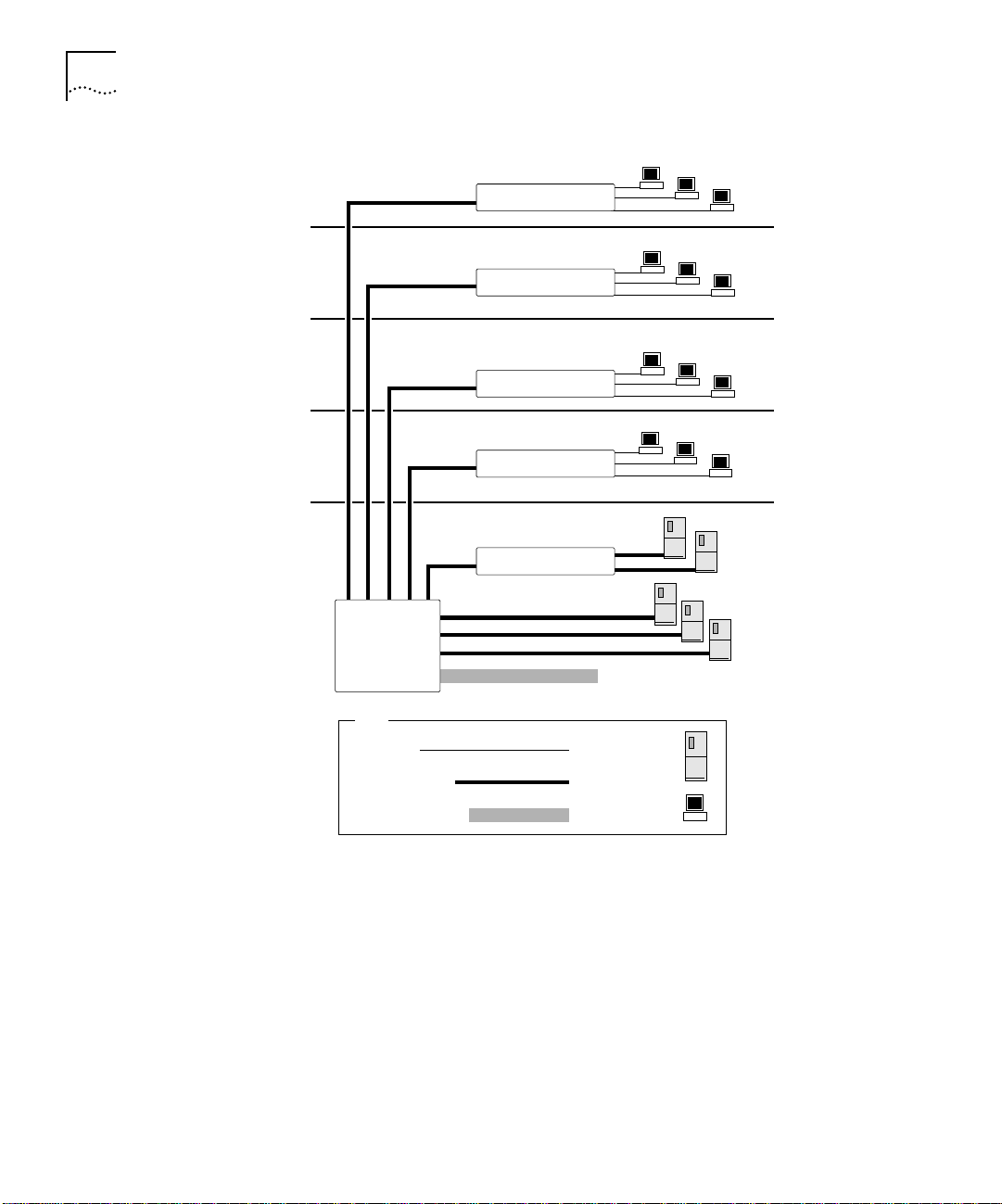
Network
Configuration
Example
This section describes where to position the Switch 3800 within your
network. One common use of the Switch 3800 is on a Gigabit Ethernet
backbone. Figure 1-2 shows an example of a Gigabit Ethernet
backbone within a building.
Page 24
1-6 CHAPTER 1: SWITCH 3800 OVERVIEW
Switch 1100
Switch 1100
Switch 1100
Switch 1100
Switch 3300
Switch 3800
To Backbone
Key
Ethernet
Fast Ethernet
Gigabit Ethernet
Server
Workstation
Figure 1-2 Switch 3800 used in a backbone configuration
The Switch 1100 on each floor has a 100Mbps full-duplex link to the
Switch 3800. A Switch 3300 is connected to a group of servers on one
floor of the building. The Switch 3800 routes IP traffic between the IP
subnets on each floor, and also provides bridged connectivity for non-IP
traffic. The Gigabit Ethernet port on the Switch 3800 connects into a
Gigabit Ethernet campus backbone.
Using Gigabit Ethernet as a backbone technology removes bottlenecks
by providing scalable bandwidth, low-latency, and high-speed data
switching.
Page 25
Switch 3800 Front View 1-7
In addition to providing a fast backbone between Ethernet LANs,
Gigabit Ethernet equipped file servers and services may be directly
attached to the Switch 3800 providing improved performance to the
Ethernet desktop.
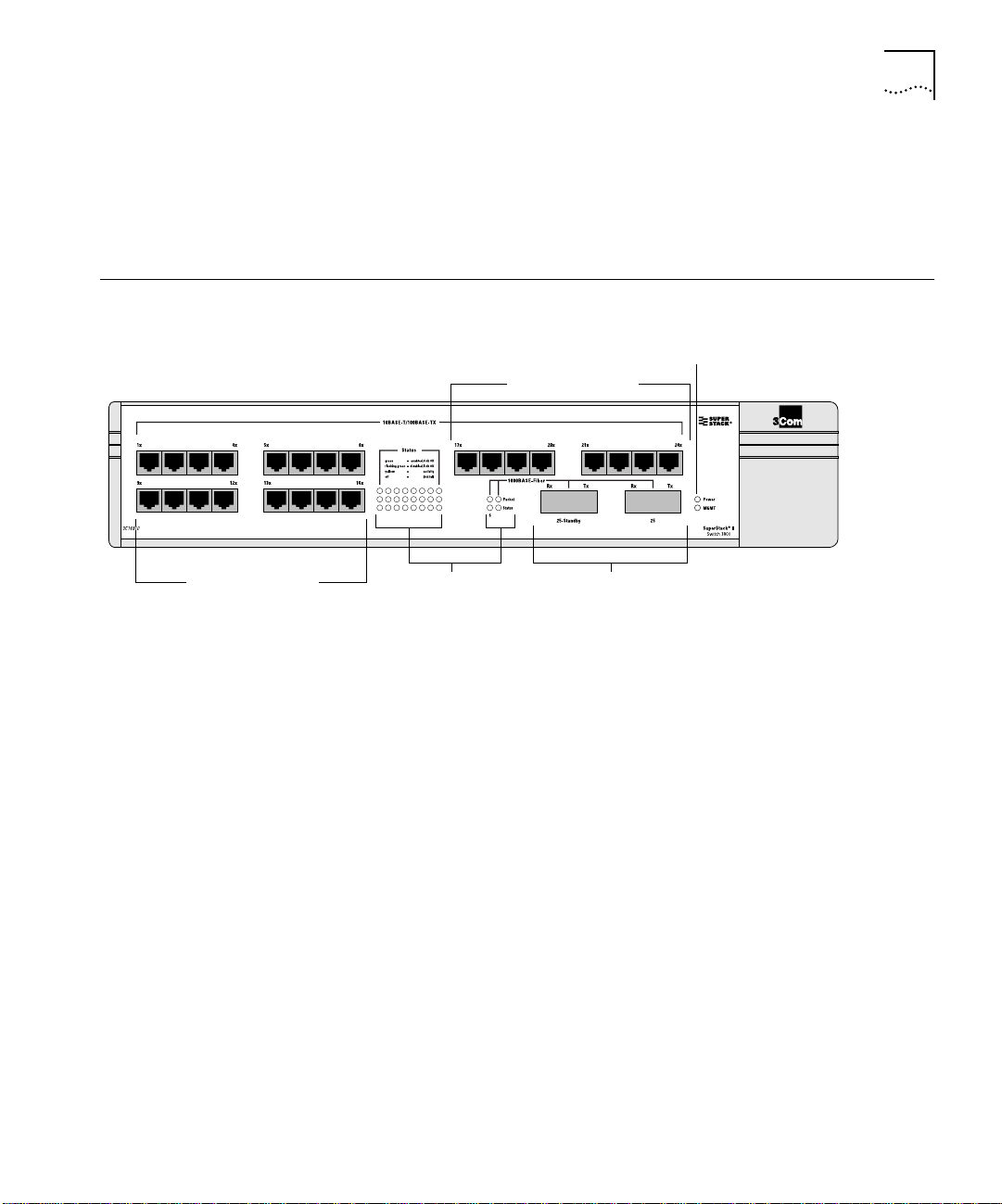
Switch 3800 Front View
10/100 Mbps ports
Figure 1-3 shows the Switch 3800 front view.
Unit status LEDs
10/100 Mbps ports
12345678
9101112131415 16
17 18 19 20 21 22 23 24
25 25
25 25
Gigabit Ethernet portsPort status LEDs
Figure 1-3 Switch 3800 front view
The front panel has the following features:
Ports
The Switch 3800 has 24 autosensing 10BASE-T/100BASE-TX ports using
standard RJ-45 connectors, and supports one Gigabit Ethernet port,
and one redundant Gigabit Ethernet port using standard Gigabit
Interface Connectors (GBICs). You must have a GBIC transceiver module
inserted to make use of these ports.
The Switch 3800 ports support the media types and distances listed in
Table 1-1.
Page 26

1-8 CHAPTER 1: SWITCH 3800 OVERVIEW
Table 1-1 Media Types and Distances
Standard Media Type Mhz/Km Rating Maximum Distance
10BASE-T Category 3 UTP Cable (10Mbps) 100 Meters
100BASE-TX Category 5 UTP Cable (100Mbps) 100 Meters
1000BASE-SX
(850 nm)
1000BASE-LX
(1300 nm)
62.5/125 um Multimode fiber
62.5/125 um Multimode fiber
50/125 um Multimode fiber
50/125 um Multimode fiber
62.5/125 um Multimode fiber
50/125 um Multimode fiber
50/125 um Multimode
10u Single-mode fiber
160
200
400
500
500
400
500
NA
220 Meters
275 Meters
500 Meters
550 Meters
550 Meters
550 Meters
550 Meters
5,000 Meters
For more information on 1000BASE-SX and 1000BASE-LX
characteristics refer to IEEE Draft P802.3z/D4.2 Tables 38-2 and 38-6.
LEDs
Table 1-2 describes the LED behavior on the Switch 3800.
Table 1-2 Switch 3800 LEDs
LED Color Indicates
10/100Mbps Port Status LEDs
Green
Yellow
Green flashing
Off
Gigabit Ethernet Port Status LEDs
Packet Yellow
Off
Status Green
Green flashing
Off
(continued)
Link is present; port is enabled.
Frames are being transmitted/received on this
port.
Link is present; port is disabled.
Link is not present.
Frames are being transmitted/received on this
port.
No activity on this port.
Link is present; port is enabled; full-duplex
operation.
Link is present; port is disabled.
Link is not present.
Page 27
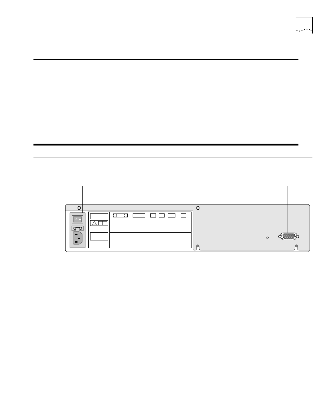
Table 1-2 Switch 3800 LEDs (continued)
LED Color Indicates
Unit Status LEDs
Power Green
Yellow
The Switch 3800 is powered up.
The Switch 3800 is indicating a power,
overheat, or fan failure.
MGMT Green
Green flashing
The Switch 3800 is operating normally.
Software download is in progress.
Power On Self Test (POST) is in progress.
Yellow
The Switch 3800 has failed its POST, or is
indicating an overheat condition.
Switch 3800 Rear View 1-9
Switch 3800 Rear View
Power socket and fuse Console port
Figure 1-4 shows the Switch 3800 rear view.
U
C
LUL
!
3C16990
SERIAL NUMBER
MAC ADDRESS
MADE IN USA
MAIN ASSEMBLY
Figure 1-4 Switch 3800 rear view
The rear panel has the following features:
Power Socket
The Switch 3800 automatically adjusts to the supply voltage. The
power supply operates down to 90 V. The fuse is suitable for both
110 V AC and 220-240 V AC operation.
Serial Number
The serial number uniquely identifies this unit. You may need this serial
number for fault-reporting purposes.
Page 28

1-10 CHAPTER 1: SWITCH 3800 OVERVIEW
MAC Address
This label shows the unique Ethernet MAC address assigned to this
device.
Console Port
The console port (9-pin, “D” type connector) is used to connect a
terminal and to carry out local out-of-band management.
Factory Defaults Table 1-3 shows the factory defaults for the Switch 3800 features.
Table 1-3 Switch 3800 Factory Defaults
Item Default Setting
Port status Enabled on all ports
Default user account admin with no password and user with no
Console port configuration 9600 baud, eight data bits, one stop bit, no
SNMP read community string Public
SNMP write community string Private
RMON history session Enabled
RMON alarms Enabled
PACE Recognition disabled
Virtual LANs One VLAN named default; all ports belong to the
802.1Q tagging All packets are untagged on the default VLAN
BOOTP Enabled on the default VLAN (default)
Spanning Tree Protocol Disabled; one defined as “s0”
IP Routing Disabled
Forwarding database aging
period
RIP Protocol Disabled
Autonegotiation On
password
parity, XON/XOFF flow control enabled
■ Send trap if load is greater than 75% of
available bandwidth
■ Send trap if there are more than 10 errors in
1,000 packets
default VLAN; no protocol filter used.
(default)
30 minutes
Page 29
2
INSTALLATION AND SETUP
This chapter describes the following:
■ How to decide where to install the Switch 3800
■ Ethernet configuration rules
■ How to install the Switch in a rack or free-standing
■ How to connect equipment to the console port
■ How to check the installation using the Power On Self-Test (POST)
Following Safety Information
Determining the Switch 3800 Location
Before installing or removing any components of the Switch, or before
carrying out any maintenance procedures, you must read the safety
information provided in Appendix A of this guide.
The Switch 3800 is suited for use in the office, where it can be
free-standing or mounted in a standard 19-inch equipment rack.
Alternatively, the device can be rack-mounted in a wiring closet or
equipment room. Two mounting brackets are supplied with the Switch.
CAUTION: When using a rack mounting system, the Switch must be
mounted on a shelf or runners. The rack mounting brackets alone are
not sufficient to support the weight of the Switch. The rack mounting
brackets are provided to ensure stability across the horizontal plane. If
you stack Switches, you must ensure that the shelf or runners are
strong enough to hold the combined weight. Ensure that the
ventilation holes are not obstructed.
After deciding where to install the Switch, make sure that:
■ You will be able to meet the configuration rules detailed in
Chapter 1.
■ The Switch is accessible and cables can be connected easily.
Page 30

2-2 CHAPTER 2: INSTALLATION AND SETUP
■ Water or moisture cannot enter the case of the unit.
■ Temperature must be within the range of 0 to 40 degrees Celsius.
■ Air-flow around the unit and through the vents in the side of the
case is not restricted. You should provide a minimum of 25mm
(1-inch) clearance.
■ No objects are placed on top of the unit.
■ Units are not stacked more than four high if the Switch is
free-standing.
Configuration Rules
for Ethernet
Installing the Switch 3800
Rack Mounting The Switch 3800 is 2U high and will fit in most standard 19-inch racks.
The connectors, supported media types, and maximum distances for
the Switch 3800 are described in Chapter 1.
The Switch 3800 can be mounted in a rack, or placed free-standing on
a tabletop.
CAUTION: The Switch should only be used in a rack if it is mounted on
runners, a shelf, or a tray to support the weight. The rack mount kits
alone are not sufficient to support the weight of the Switch. The rack
mount kits must not be used to suspend the Switch from under a table
or desk, or attach it to a wall.
To install the mounting brackets on the Switch, follow these steps:
1 Place the Switch the right way up on a hard flat surface, with the front
facing toward you.
2 Remove the existing screws from the sides of the chassis.
3 Locate a mounting bracket over the mounting holes on one side of the
unit.
4 Insert the four screws and fully tighten with a suitable screwdriver, as
shown in Figure 2-1.
Page 31

Installing the Switch 3800 2-3
Figure 2-1 Fitting the mounting bracket
5 Repeat the three previous steps for the other side of the Switch.
6 Refer to the instructions that shipped with your rack, runners, shelf or
tray to complete the installation of the Switch into the mounting rack.
CAUTION: When using rack mounting runners, a shelf, or a tray, make
sure that the ventilation holes on the side of the Switch are not
obstructed.
7 Connect cables.
Free-Standing The Switch 3800 is supplied with four self-adhesive rubber pads. Apply
the pads to the underside of the device by sticking a pad in the marked
area at each corner of the Switch.
Page 32

2-4 CHAPTER 2: INSTALLATION AND SETUP
Stacking the Switch
and Other Devices
Connecting Equipment to the Console Port
Up to four units can be placed on top of one another. If mixing Switch
3800, Switch 3000 FX, Switch 1000, Switch 1200, and other
SuperStack
®
II hubs, the smaller units must be positioned at the top
using rubber pads.
This section relates only to physically placing the devices on top of each
other. The Switch cannot be used to form a logical stack. It cannot be
linked to other Switches using special expansion cables to form a larger
Switch.
Apply the pads to the underside of the device by sticking a pad in the
marked area at each corner of the Switch. Place the devices on top of
each other, ensuring that the pads of the upper device line up with the
recesses of the lower device.
Connection to the console port is used for direct local management.
The Switch 3800 console port settings are set as follows:
■ Baud rate — 9600
■ Data bits — 8
■ Stop bit — 1
■ Parity — None
■ Flow control — XON/XOFF
The terminal connected to the console port on the Switch must be
configured with the same settings. This procedure will be described in
the documentation supplied with the terminal.
Appropriate cables are available from your local supplier. If you make
your own cables, pin-outs for a DB-9 male console connector are
described in Table 2-1.
Table 2-1 Console Connector Pin-Outs
Function Pin Number
TXD (transmit data) 3
RXD (receive data) 2
GND (ground) 5
Page 33

Connecting Equipment to the Console Port 2-5
Figure 2-2 shows the pin-outs for a 9-pin to RS-232 25-pin null modem
cable.
Switch 3800
Cable connector: 9-pin female
Screen
TxD
RxD
Ground
RTS
CTS
DSR
DCD
DTR
Figure 2-2 Null modem cable pin-outs
Shell
3
2
5
7
8
6
1
4
PC/Terminal
Cable connector: 25-pin male/female
Screen
1
3
2
7
4
20
5
6
8
RxD
TxD
Ground
RTS
DTR
CTS
DSR
DCD
Figure 2-3 shows the pin-outs for a 9-pin to 9-pin PC-AT serial null
modem cable.
Switch 3800
Cable connector: 9-pin female
Screen
DTR
TxD
RxD
CTS
Ground
DSR
RTS
DCD
Shell
4
3
2
8
5
6
7
1
PC-AT Serial Port
Cable connector: 9-pin female
1
2
3
4
5
6
7
8
Screen
DCD
RxD
TxD
DTR
Ground
DSR
RTS
CTS
Shell
Figure 2-3 PC-AT serial cable pin-outs
Page 34

2-6 CHAPTER 2: INSTALLATION AND SETUP
Powering-up the Switch
Checking the Installation
Power On Self-Test
(POST)
Logging on for the First Time
To power-up the Switch, follow these steps:
1 Connect the power cable to the Switch.
2 Connect the power cable to the wall outlet.
3 If necessary, turn the on/off switch to the on position.
After turning on power to the Switch 3800, the device performs a
Power On Self-Test (POST).
During the POST, all ports are temporarily disabled, the packet LED is
off, the power LED is on, and the MGMT LED flashes green. The
MGMT LED flashes until the Switch has successfully passed the POST.
If the Switch passes the POST, the MGMT LED stops blinking and
remains green. If the Switch fails the POST, the MGMT LED shows a
solid yellow light.
After the Switch has completed the POST, it is operational. Once
operational, you can log on to the Switch and configure an IP address
for the default VLAN (named default).
To manually configure the IP settings, perform the following steps:
1 Connect a terminal or workstation running terminal emulation software
to the console port.
2 At your terminal, press [Return] until you see the logon prompt.
3 At the logon prompt, enter the default user name admin to log on
with administrator privileges. For example:
login: admin
Administrator capabilities allow you to access all Switch functions. For
more information on Switch security, refer to Chapter 3.
4 At the password prompt, press [Return].
The default name, admin, has no password assigned. When you have
successfully logged on to the Switch, the command-line prompt
displays the name of the Switch in its prompt.
Page 35

Logging on for the First Time 2-7
5 Assign an IP address and subnetwork mask for VLAN default. The
example below assigns an IP address of 123.45.67.8 and a subnetwork
mask of 255.255.255.0.
config vlan default ipaddress 123.45.67.8 255.255.255.0
Your changes take effect immediately.
6 Save your configuration changes so that they will be in effect after the
next Switch reboot, by typing
save
For more information on saving configuration changes, refer to
Chapter 10.
7 When you are finished using the facility, log out of the Switch by
typing
logout
Page 36

2-8 CHAPTER 2: INSTALLATION AND SETUP
Page 37

3
ACCESSING THE SWITCH
This chapter describes the following information that you can use to
begin managing the Switch 3800:
■ Security access level overview
■ Configuring the Switch for management
■ Switch management methods
■ Configuring SNMP
CAUTION: For configuration changes to be retained through a Switch
power cycle or reboot, you must issue a SAVE command after you have
made the change. For more information on the SAVE command, refer
to Chapter 10.
Security Access Levels
User Access Level A user-level account can view all manageable parameters, with the
The Switch 3800 supports two security access levels:
■ User
■ Administrator
following exceptions:
■ User account information
■ SNMP community strings
A user-level account can use the ping command to test device
connectivity. A user-level account can also change the password
assigned to the account name. If you have logged on with a user
access level, the command-line prompt ends with a (>) sign. For
example:
3C16910>
Page 38

3-2 CHAPTER 3: ACCESSING THE SWITCH
Administrator Access
Level
An administrator-level account can view and change all Switch
parameters, add and delete users, and change the password
associated with any account name. The administrator can disconnect a
Telnet management session. If this happens, the user is notified that
the session has been terminated.
If you have logged on with administrator access level, the
command-line prompt ends with a (#) sign. For example:
3C16910#
If an asterisk (*) appears in front of the command-line prompt, it
indicates that you have outstanding configuration changes that have
not been saved. For example:
*3C16910#
Default Accounts By default, the Switch is configured with two accounts, as shown in
Table 3-1.
Table 3-1 Default Accounts
User Name Access Level
admin This user can access and change all manageable
user This user can view (but not change) all manageable
parameters. The admin account cannot be deleted.
parameters, with the following exceptions:
■ This user cannot view the user account database.
■ This user cannot view the SNMP community strings.
This user has access to the ping command.
The default accounts do not have passwords assigned to them.
Passwords must have a minimum of 4 characters and can have a
maximum of 12 characters.
Adding a Password to the Default admin Account
To add a password to the default admin account, follow these steps:
1 Logon to the Switch using the name admin.
2 At the password prompt, press [Return].
3 Add a default admin password by typing the following:
config account admin
Page 39

4 Enter the new password at the prompt.
5 Re-enter the new password at the prompt.
6 Save your changes by typing
save
Security Access Levels 3-3
Creating a
Management
Account
The Switch can have a total of three management accounts. You can
use the default names (admin and user), or you can create new names
and passwords for the accounts. Passwords must have a minimum of
four characters and can have a maximum of 12 characters.
The account name “admin” cannot be deleted.
To create a new account, follow these steps:
1 Logon to the Switch using the name admin.
2 At the password prompt, press [Return].
3 Add a new user by typing the following:
create account [admin | user] <username>
4 Enter the password at the prompt.
5 Re-enter the password at the prompt.
6 Save your changes by typing
save
Changing Account Passwords
To add a password to a user account, follow these steps:
1 At the logon prompt, enter your user name and password. Note that
they are both case-sensitive. Ensure that you have entered a user name
and password with administrator privileges.
■ If you are logging on for the first time, use the default user name
admin to log on with administrator privileges. For example:
login: admin
2 Add an account password by using the following command:
config account <name>
for example:
config account user
Page 40

3-4 CHAPTER 3: ACCESSING THE SWITCH
3 Enter the new password at the prompt.
4 Re-enter the new password at the prompt.
5 Save your changes by typing
save
If you forget your password contact your local technical support
representative, who will advise on your next course of action.
Viewing Switch Accounts
To view the accounts that have been created, you must have
administrator privileges. Type the following to see the accounts:
show accounts
Output from the show accounts command is displayed below.
#show accounts
User Name Access LoginOK Failed Session
------------- ------ ------- ------ ------- admin R/W 0 0
user RO 0 0
Methods of Managing the Switch 3800
Deleting a Switch Account
To delete a switch account, you must have administrator privileges.
Use the following command to delete an account:
delete account <username>
You can manage the Switch 3800 using the following methods:
■ Access the command-line interface by connecting a terminal (or
workstation with terminal emulation software) to the Switch 3800
console port.
■ Access the command-line interface over a TCP/IP network using a
Telnet connection.
■ Use an SNMP Network Manager over a network running the IP
protocol.
The Switch can support up to four user sessions concurrently (for
example, one console port and three Telnet connections).
Page 41

Using Telnet 3-5
Using the Console
Interface
The command-line interface built into the Switch is accessible by way
of the 9-pin, RS-232 console port located on the rear of the unit.
For more information on the console port pin-outs, refer to Chapter 2.
Once the connection is established, you will see the system prompt and
you may log on.
Using Telnet Any Telnet facility should be able to communicate with the Switch over
a TCP/IP network. Up to three active Telnet sessions can access the
Switch concurrently. The Telnet connection will time out after three
minutes of inactivity. If a connection to a Telnet session is lost
inadvertently, the Switch will terminate the session within three
minutes.
Before you can start a Telnet session you must set up the IP parameters
described in “Configuring Switch IP Parameters” on page 3-5. Telnet is
enabled by default.
To open the Telnet session, you must specify the IP address of the
device that you want to manage. Check the user manual supplied with
the Telnet client you are using, if you are unsure of how to do this.
Configuring Switch IP
Parameters
Once the connection is established, you will see the system prompt and
you may log on.
In order to manage the Switch by way of a Telnet connection or by
using an SNMP Network Manager, you must configure the Switch IP
parameters. Switch IP parameters are configured on a per-VLAN basis.
Using a BOOTP Server
If you are using IP and you have a BOOTP server set up correctly on
your network, you will need to add the Switch Media Access Control
(MAC) address, the IP address, subnetwork mask, and default gateway
to the BOOTP server. The Switch MAC address is shown on the rear
label of the Switch.
Once this is done, the IP address, subnetwork mask, and default
gateway for the Switch will be downloaded automatically. You can then
start managing the Switch without further configuration.
Page 42

3-6 CHAPTER 3: ACCESSING THE SWITCH
You can enable BOOTP on a per-VLAN basis by using the following
command:
enable bootp vlan [<name> | all]
Manually Configuring the IP Settings
If you are using IP without a BOOTP server, you must enter the IP
parameters for the Switch in order for the SNMP Network Manager or
Telnet software to communicate with the device. To assign IP
parameters to the Switch, you must do the following:
■ Logon to the Switch with administrator access level.
■ Assign an IP address and subnetwork mask to a VLAN.
The Switch comes configured with a default VLAN named default. In
order to use Telnet or an SNMP Network Manager, you must have at
least one VLAN on the Switch, and it must be assigned an IP address
and subnetwork mask. IP addresses are always assigned to a VLAN. The
Switch 3800 can be assigned multiple IP addresses. For information on
creating and configuring VLANs, refer to Chapter 5, “Virtual LANs
(VLANs).”
To manually configure the IP settings, perform the following steps:
1 Connect a terminal or workstation running terminal emulation software
to the console port.
2 At your terminal, press [Return] one or more times until you see the
logon prompt.
3 At the logon prompt, enter your user name and password. Note that
they are both case-sensitive. Ensure that you have entered a user name
and password with administrator privileges.
■ If you are logging on for the first time, use the default user name
admin to log on with administrator privileges. For example:
login: admin
The administrator access level allow you to access all Switch
functions. The default user names have no passwords assigned. For
more information on Switch security, refer to “Security Access
Levels,” on page 3-1.
■ If you have been assigned a user name and password with
administrator privileges, enter them at the logon prompt.
Page 43

Using Telnet 3-7
4 At the password prompt, enter the password and press [Return].
When you have successfully logged on to the Switch, the
command-line prompt displays the name of the Switch in its prompt.
5 Assign an IP address and subnetwork mask for the default VLAN by
using the following command
config vlan <name> ipaddress <ipaddress> {<subnet_mask>}
For example:
config vlan default ipaddress 123.45.67.8 255.255.255.0
Your changes take effect immediately.
6 Configure the default route for the Switch using the following
command:
config iproute add default <ipaddress> {<metric>}
For example:
config iproute add default 123.0.0.1 1
Disconnecting a
Telnet Session
7 Save your configuration changes so that they will be in effect after the
next Switch reboot, by typing
save
For more information on saving configuration changes, refer to
Chapter 10.
8 When you have finished using the facility, log out of the Switch by
typing
logout
For security purposes, an administrator access level account can
disconnect a management session that has been established by way of
a Telnet connection. If this happens, the user logged on by way of the
Telnet connection is notified that the session has been terminated.
To terminate a Telnet session, follow these steps:
1 Logon to the Switch with an administrator access level.
2 Determine the session number of the session you want to terminate by
typing
show session
Page 44

3-8 CHAPTER 3: ACCESSING THE SWITCH
Sample output from the show session command is as follows:
3C16910:2 # sh sess
# Login Time User Type Location
============================================================
0 Tue Mar 10 11:10:53 1998 admin console serial
4 Tue Mar 10 13:11:13 1998 user telnet 192.207.37.168
Terminate the session by typing
clear session <session_number>
Disabling Telnet
Access
By default, Telnet services are enabled on the Switch. You can choose
to disable Telnet. To do so, enter
disable telnet
To re-enable Telnet on the Switch, at the console port enter
enable telnet
You must be logged on as an administrator to enable or disable Telnet.
Using SNMP Any Network Manager running the Simple Network Management
Protocol (SNMP) can manage the Switch, provided the Management
Information Base (MIB) is installed correctly on the management
station.
Each Network Manager provides its own user interface to the
management facilities. 3Com’s Transcend
Managers all have facilities for managing the Switch.
The following sections describe how to get started if you want to use
an SNMP manager. It assumes you are already familiar with SNMP
management. If not, refer to the following publication:
“The Simple Book”
by Marshall T. Rose
ISBN 0-13-8121611-9
Published by Prentice Hall
®
range of Network
Page 45

Using SNMP 3-9
Accessing Switch
Agents
In order to have access to the SNMP agent residing in the Switch, at
least one VLAN on the Switch must have an IP address assigned to it.
For more information on assigning an IP address, refer to “Manually
Configuring the IP Settings,” on page 3-6.
Saving
Configuration
Changes
If you make configuration changes to the Switch using an SNMP
manager, you must save the changes so that they are not lost on the
next Switch reboot. You can save your changes by using the SNMP save
attribute, or by issuing the
save command from the command line
interface.
Supported MIBs In addition to private MIBs, the Switch 3800 supports the standard
MIBs listed in Table 3-2.
Table 3-2 Supported MIBs
Description RFC Number
MIB II 1213
Bridge MIB 1493
RMON 1757
RMON II Probe Configuration 2021
Evolution of Internet 1573
Supported Traps A trap is a message sent by an SNMP agent to an authorized trap
receiver (usually a network management station) to indicate the
occurrence of a significant event, such as an error condition or a
threshold that has been reached. The Switch 3800 supports the traps
listed in Table 3-3.
Table 3-3 Supported Traps
Trap Description
Cold start Indicates that the device is reinitializing itself.
Link up Indicates that the device recognizes that one of its
Link down Indicates that the device recognizes a failure in one of
Rising alarm Indicates that an RMON alarm entry has crossed its
(continued)
communication links has come up.
the communication links represented in the agent’s
configuration.
rising threshold
Page 46

3-10 CHAPTER 3: ACCESSING THE SWITCH
Table 3-3 Supported Traps (continued)
Trap Description
Falling alarm Indicates that an RMON alarm entry has crossed its
Fan fail Indicates that one or more of the cooling fans inside
Fan okay Indicates that a fan has transitioned out of a failure
Overheat Indicates that the onboard temperature sensor has
Login attempt failure Indicates that three consecutive bad logon attempts
falling threshold.
the device has failed. A Fan okay trap will be issued
once the fan has attained normal operation.
state and is now operating correctly.
reported an overheat condition. The system will
shutdown until the device has sufficiently cooled such
that operation may begin again. A Cold start trap will
be issued when the device comes back on line.
have occurred.
Configuring SNMP
Settings
The following SNMP parameters can be configured on the Switch:
■ Authorized trap receivers — An authorized trap receiver can be
one or more network management stations on your network. The
Switch sends SNMP traps to the trap receiver. You can have a
maximum of six trap receivers configured for each Switch 3800.
■ Community strings — The community strings allow a simple
method of authentication between the Switch and the remote
Network Manager. There are two community strings on the Switch
3800. The read community string provides read-only access to the
Switch. The default read community string is public. The write
community string provides read and write access to the Switch. The
default write community string is private. The community string for
all authorized trap receivers must be configured on the Switch in
order for the trap receiver to receive Switch-generated traps.
■ System contact (optional) — The system contact is a text field that
allows you to enter the name of the person(s) responsible for
managing the Switch.
■ System name — The system name is the name that you have
assigned to this Switch. The default name is 3C16910.
■ System location (optional) — Using the system location field, you
can enter a location for this Switch.
Page 47

Using SNMP 3-11
Table 3-4 describes SNMP configuration commands.
Table 3-4 SNMP Configuration Commands
Command Description
config vlan <name> ipaddress <ip_address> {<mask>} Configures an IP address for the VLAN. This is
enable snmp access Allows you to turn on SNMP support for the
enable snmp trap Allows you to turn on SNMP trap support.
config snmp add <ipaddress> Allows you to add the IP address of an SNMP
config snmp add trapreceiver <ipaddress> {<string>} Allows you to add the IP address of a specified
config snmp community [read | readwrite] <string> Allows you to configure the SNMP read and
config snmp delete [<ipaddress> | all] Allows you to delete the IP address of a specified
config snmp delete trapreceiver [<ip_address> | all] Allows you to delete the IP address of a specified
config snmp syscontact <string> Allows you to configure the name of the system
config snmp sysname <string> Allows you to configure the name of the
config snmp syslocation <string> Allows you to configure the location of the
required in order to use an SNMP manager.
Switch.
management station to the access list. Up to six
addresses can be specified.
trap receiver. A maximum of six trap receivers is
allowed.
write community strings. The community string
can have a maximum of 32 characters.
SNMP management station or all SNMP
management stations.
trap receiver or all authorized trap receivers. If
you delete all trap receiver addresses, any
machine can have SNMP management access to
the Switch.
contact. A maximum of 32 characters is allowed.
Switch. The sysname appears in the command
line interface prompt. A maximum of 32
characters is allowed. The default sysname is
3C16910.
Switch. A maximum of 32 characters is allowed.
Page 48

3-12 CHAPTER 3: ACCESSING THE SWITCH
Displaying SNMP
Settings
To display the SNMP settings configured on the Switch 3800, use the
following command:
show management
This command displays the following information:
■ Enable/disable state for telnet, SNMP, and web access
■ SNMP community strings
■ Authorized SNMP station list
■ SNMP trap receiver list
■ Logon statistics
Resetting and
To reset or disable SNMP settings, use the commands in Table 3-5.
Disabling SNMP
Table 3-5 SNMP Reset and Disable Commands
Command Description
disable snmp access Allows you to disable SNMP on the Switch.
disable snmp trap Allows you to prevent SNMP traps from being sent from
unconfig management Restores default values to all SNMP-related entries.
the Switch.
Checking Basic Connectivity
The Switch 3800 has the following two facilities for checking basic
connectivity:
■ ping
■ traceroute
Ping The ping command allows you to send Internet Control Message
Protocol (ICMP) echo messages to a remote IP device. The ping
command is available for both the user and administrator privilege
level.
The ping command syntax is as follows:
ping {continuous} {size <n>} <ip_address>
Page 49

Configuring Ports 3-13
Options for the ping command are described in Table 3-6.
Table 3-6 Ping Command Parameters
Parameter Description
continuous Allows you to specify ICMP echo messages to be sent
size <n> Allows you to specify the size of the packet.
continuously.
Traceroute The traceroute command allows you to trace the routed path between
the Switch and a destination endstation.
The traceroute command syntax is as follows:
traceroute <ip_address>
where ip_address is the IP address of the destination endstation.
Configuring Ports Ports on the Switch 3800 can be configured in the following ways:
Enabling and
Disabling Ports
■ Enabling and disabling individual ports
■ Configuring autonegotiation
■ Creating load-sharing groups on multiple ports
By default, all ports are enabled. To enable or disable one or more
ports, use the following command:
[enable | disable] port <portlist>
For example, to disable ports 3, 5, and 6, enter the following:
disable port 3,5-6
Even though a port is disabled, the link remains enabled for diagnostic
purposes.
Page 50

3-14 CHAPTER 3: ACCESSING THE SWITCH
Configuring
Autonegotiation
By default, the Switch 3800 is configured to use autonegotiation for all
ports. Autonegotiation on 10/100 Mbps ports is used to automatically
determine speed and duplex settings. You can select to manually
configure the duplex and speed settings of 10/100 Mbps ports. Manual
configuration would be used when the remote device does not support
autonegotiation or when an interoperability issue exists.
The Switch 3800 Gigabit Ethernet port only supports a speed of 1,000
Mbps and full duplex. Even though these parameters are fixed,
autonegotiation on Gigabit links still allows proper link initialization and
should be used whenever possible. Manual configuration would be
used when the remote device does not support autonegotiation or
when an interoperability issue exists.
10/100 port settings Fast Ethernet ports can connect to either 10BASE-T or 100BASE-TX
networks. By default, the ports autonegotiate port speed and duplex
settings. You can manually determine these settings by turning
autonegotiation off and providing speed and duplex settings. To
configure port speed and duplex settings on 10/100 Mbps ports, use
the following command:
config port <portlist> auto off (speed [10 | 100]} duplex
[half | full]
To restore autonegotiation, use the following command:
config port <portlist> auto on
Gigabit port settings By default the Gigabit port on the Switch 3800 uses autonegotiation to
establish proper link initialization. Speed and duplex settings cannot be
modified. To tur n off autonegotiation, use the following command:
config port <portlist> auto off duplex full
The duplex setting must be provided even though the duplex setting
may not be modified. To restore autonegotiation, use the following
command:
config port <portlist> auto on
Page 51

Load Sharing 3-15
Load Sharing Load sharing with the Switch 3800 allows you to increase bandwidth
and resilience by using a group of ports to carry traffic in parallel
between Switches. The sharing algorithm allows the Switch to use
multiple ports as a single logical port. For example, VLANs see the
load-sharing group as a single virtual port. The algorithm also
guarantees packet sequencing between clients.
If a port in a load-sharing group fails, traffic is redistributed to the
remaining ports in the load-sharing group. If the failed port becomes
active again, traffic is redistributed to include that port.
Load sharing is most useful in cases where the traffic transmitted from
the Switch to the load-sharing group is sourced from an equal or
greater number of ports on the Switch. For example, traffic transmitted
to a 2-port load-sharing group should originate from a minimum of
two other ports on the same Switch.
This feature is supported between Switch 3800 Switches only, but may
be compatible with third-party trunking or sharing algorithms.
Configuring Load
Sharing
To set up the Switch 3800 to load share among ports, you must create
a load-sharing group of ports. Load-sharing groups are defined
according to the following rules:
■ Ports on the Switch are divided into groups of two or four.
■ Ports in a load-sharing group must be contiguous.
■ Valid port combinations are distinguished by the outlined boxes in
Table 3-7.
■ The first port in the load-sharing group is configured to be the
master logical port. This is the reference port used in configuration
commands. It can be thought of as the virtual port representing the
entire port group.
Table 3-7 shows the allowable load-sharing port group combinations
for the Switch 3800.
Page 52

3-16 CHAPTER 3: ACCESSING THE SWITCH
Table 3-7 Port Combinations for the Switch 3800
Load-sharing
Group
4-port groups x x x x x x x x x x x x x x x x x x x x x x x x
2-port groups x x x x x x x x x x x x x x x x x x x x x x x x
1 2 3 4 5 6 789012 3 4 5 6 7 8 9 0 1 2 3 4 5
1 1 1 1 1 1 1 1 1 1 2 2 2 2 2 2
When you define a load-sharing group, you assign a group of ports to
a single, logical port number. To enable or disable a load-sharing group,
use the following commands:
enable sharing <master_port> grouping <portlist>
disable sharing <master_port>
The following example defines a load-sharing group that contains ports
4 through 7, and uses the first port in the group as the master logical
port 4:
enable sharing 4 grouping 4-7
In this example, logical port 4 represents physical ports 4 through 7.
When using load sharing, you should always reference the master
logical port of the load-sharing group (port 4 in the previous example)
when configuring or viewing VLANs. VLANs configured to use other
ports in the load-sharing group will have those ports deleted from the
VLAN when load sharing becomes enabled.
Verifying the Load
Sharing
Configuration
Current Limitations
of Load Sharing
The show port config output screen shows all of the ports that are
involved in load sharing, and the associated master port.
The following describes implementation restrictions that currently apply
to load sharing:
■ The load-sharing group must not participate in a spanning tree. If
the VLANs using the load-sharing group are also members of a
spanning tree, the ports associated with the load-sharing group
must have spanning tree disabled.
■ A port involved in a load-sharing group must not be disabled.
Page 53

SmartRedundancy 3-17
SmartRedundancy SmartRedundancy for the Switch 3800 refers to fail-over behavior of
the main and standby Gigabit Ethernet ports. SmartRedundancy allows
the Switch to always use the main link if it is available. For example, if
only the standby link is available it will be used, but if the main link
becomes available again the link will switch back to the main from the
standby. With SmartRedundancy disabled, the first link available will be
used; only if that link becomes unavailable will the Switch attempt to
use the other link. By default, SmartRedundancy is enabled.
Port Commands Table 3-8 describes port commands.
Table 3-8 Port Commands
Command Description
config port <portlist> auto on Allows you to enable autonegotiation on a 10/100
config port <portlist> auto off {speed
[10 | 100]} duplex [half | full]
config port <portlist> auto off duplex
full
enable port <portlist> Allows you to enable one or more ports.
enable sharing <master_port> grouping
<portlist>
enable smartredundancy <portlist> Allows you to enable the SmartRedundancy feature on
disable port <portlist> Allows you to disable one or more ports. Even when
disable sharing <master_port> Allows you to disable a load-sharing group of ports.
(continued)
Mbps or Gigabit port.
Allows you to change the configuration of a group of
10/100 Mbps ports. Specify the following:
■ auto off — The port will not autonegotiate the
settings.
■ speed — The speed of the port (for 10/100 Mbps
ports only).
■ duplex — The duplex setting (half- or full-duplex).
Allows you to disable autonegotiation on a Gigabit
port.
Allows you to define a load-sharing group of ports.
The ports specified in <portlist> are grouped to the
master port.
the redundant Gigabit Ethernet port. When the
SmartRedundancy feature is enabled, the Switch
always uses the primary link when the primary link is
available. The default setting is enabled.
disabled, the link is available for diagnostic purposes.
Page 54

3-18 CHAPTER 3: ACCESSING THE SWITCH
Table 3-8 Port Commands (continued)
Command Description
disable smartredundancy <portlist> Allows you to disable the SmartRedundancy feature. If
show port <portlist> config Displays state, link status, speed, and autonegotiation
show port <portlist> stats Displays port information including physical layer
show port <portlist> errors Displays error information for one or more ports.
show port <portlist> collisions Displays real-time collision statistics.
show port <portlist> packet Displays a histogram of packet statistics for one or more
show port <portlist> util Displays port utilization by percentage, bytes per
the feature is disabled, the Switch changes the active
link only when the current active link becomes
inoperable.
setting for each port.
configuration and statistics.
ports.
second, or packets per second. Use the space bar to
toggle between percentage, bytes per second, or
packets per second. Use the clear counters command to
reset values.
Page 55

4
COMMANDS
This chapter contains a description of each command-line interface
command for the Switch 3800. It also provides the following
information related to Switch 3800 commands:
■ Command syntax
■ Line-editing commands
■ Command history substitution
If an asterisk (*) appears in front of the command-line prompt, it
indicates that you have outstanding configuration changes that have
not been saved. For example:
*3C16910#
In order for configuration changes to be retained through a Switch
power cycle or reboot, you must issue a SAVE command after you
have made the change. For more information on the SAVE command,
refer to Chapter 10.
Understanding the Command Syntax
This section describes the steps to take when entering a command.
Refer to the sections that follow for detailed information on using the
command-line interface.
To use the command-line interface, follow these steps:
1 When entering a command at the prompt, ensure that you have the
appropriate privilege level.
Most configuration commands require you to have the Administrator
privilege level.
2 Enter the command name.
Page 56

4-2 CHAPTER 4: COMMANDS
3 After entering the complete command, press [Return].
Syntax Helper The command-line interface has a built-in syntax helper. If you are
If the command does not include a parameter, skip to Step 3. If the
command requires more information, or if you want to include optional
parameters, continue to Step 2a.
a If the command has additional parameters include them after the
command name.
b If the command includes a parameter, enter the parameter name,
and its values.
The parameters values may include numerics, strings, or addresses,
depending on the parameter.
unsure of the complete syntax for a particular command, enter as
much of the command as possible. The syntax helper will provide you
with a list of options for the remainder of the command.
The syntax helper also provides assistance if you have entered an
incorrect command.
Command
Completion
The Switch provides command completion by way of the [Tab] key. If
you enter a partial command, pressing the [Tab] key fills in the
remainder of the command. If command options exist, they are
displayed. The full command is then redisplayed and the cursor is
placed at the end of the command.
Abbreviated Syntax Abbreviated syntax is the shortest, unambiguous, allowable
abbreviation of a command, parameter, or value. Typically, this is the
first three letters of the command.
Command Shortcuts All named components of the Switch configuration must have a unique
name. When you enter a command to configure a named component,
you do not need to use the keyword of the component. For example,
to create a VLAN, you must enter a unique VLAN name:
create vlan engineering
Once you have created the VLAN with a unique name, you can then
eliminate the keyword vlan from all other commands that require the
name to be entered. For example the following command:
Page 57

Understanding the Command Syntax 4-3
config vlan engineering add port 1-3,6
could use the following shortcut:
config engineering add port 1-3, 6
Numerical Ranges Commands that require you to enter one or more port numbers use
the parameter,
<portlist>, in the syntax. A portlist can be a range of
numbers, for example:
port 1-3
You can add additional port numbers to the list, separated by a
comma:
port 1-3,6,8
Names All named components of the Switch configuration must have a unique
name. Names must begin with an alphabetical character delimited by
white space, unless enclosed in quotation marks.
Symbols You may see a variety of symbols shown as part of the command
syntax. These symbols explain how to enter the command, and you do
not type them as part of the command itself. Table 4-1 summarizes
command syntax symbols.
Table 4-1 Command Syntax Symbols
Symbol Description
angled brackets < > Enclose a variable or value. You must specify the variable or value. For example, in
square brackets [ ] Enclose a required value or list of required arguments. One or more values or
(continued)
the syntax
config vlan <name> ipaddress <ip_address>
you must supply a VLAN name for <name> and an address for <ip_address> when
entering the command. Do not type the angle brackets.
arguments can be specified. For example, in the syntax
disable vlan [<name> | all]
you must specify either the VLAN name for <name>, or the keyword “all” when
entering the command. Do not type the square brackets.
Page 58

4-4 CHAPTER 4: COMMANDS
Table 4-1 Command Syntax Symbols (continued)
Symbol Description
vertical bar | Separates mutually exclusive items in a list, one of which must be entered. For
braces { } Enclose an optional value or a list of optional arguments. One or more values or
Line-Editing Commands
example, in the syntax
config snmp community [read | write] <string>
you must specify either the read or write community string in the command. Do not
type the vertical bar.
arguments can be specified. For example, in the syntax
show vlan {<name> | all}
you can specify either a particular VLAN or the keyword “all.” If you do not specify
an argument, the command will show all VLANs. Do not type the braces.
Table 4-2 describes the line-editing commands available using the
command-line interface.
Table 4-2 Line-Editing Commands
Command Description
Backspace Deletes character to the left of cursor and shifts remainder of line to left.
Delete or [Ctrl] + D Deletes character under cursor and shifts remainder of line to left.
[Ctrl] + K Deletes characters from under cursor to the end of the line.
Insert Toggles on and off. When toggled on, inserts text and pushes previous text to right.
Left Arrow Moves cursor to left.
Right Arrow Moves cursor to right.
Home or [Ctrl]+A Moves cursor to first character in line.
End or [Ctrl]+E Moves cursor to last character in line.
[Ctrl]+L Clears the screen and moves the cursor to the beginning of the line.
Up Arrow Displays the previous command in the command history buffer, and places cursor at
Down Arrow Displays the next command in the command history buffer, and places cursor at end
end of command.
of command.
Page 59

Command History Substitution 4-5
Command History Substitution
Common Commands
The Switch 3800 “remembers” the last 50 commands you enter. You
can display a list of these commands by typing
history
Table 4-3 describes common commands used to manage the Switch.
Commands specific to a particular feature are described in the other
chapters of this guide.
Table 4-3 Common Commands
Command Description
create account [admin | user] <username>
{<password>}
create vlan <name> Allows you to create a VLAN. For more information
config account <username> {<password>} Allows you to configure a user account password.
config time <time> Allows you to configure the system date and time.
config vlan <name> ipaddress <ip_address>
{<mask>}
enable bootp vlan [<name> | all] Allows you to enable BOOTP for one or more
clear session <number> Allows you to terminate a Telnet session from the
disable bootp vlan [<name> | all] Allows you to disable BOOTP for one or more VLANs.
disable port <portlist> Allows you to disable or partition a port.
disable telnet Allows you to disable Telnet access to the Switch.
delete account <username> Allows you to delete a user account.
delete vlan <name> Allows you to delete a VLAN.
logout | quit Allows you to logout of a console or Telnet session. If
(continued)
Allows you to create a user account. For more
information on creating accounts, refer to Chapter 3.
on VLANs, refer to Chapter 5.
The format for <time> is:
mm/dd/yyyy hh:mm
The time uses a 24-hour clock format.
Allows you to configure an IP address and subnet
mask for a VLAN.
VLANs. For more information on using BOOTP, refer
to Chapter 3.
Switch.
used during a Telnet session, also closes the TCP
Telnet session.
Page 60

4-6 CHAPTER 4: COMMANDS
Table 4-3 Common Commands (continued)
Command Description
unconfig switch {all} Allows you to reset all Switch parameters (with the
exception of defined VLANs and IP addresses) to the
factory defaults. If you specify the keyword “all”, the
IP addresses are reset as well.
Switch 3800 Commands
The tables in this section list all of the commands used on the Switch
3800. The commands are organized by the following categories:
■ General Switch commands
■ User account commands
■ Switch management commands
■ VLAN commands
■ Protocol commands
■ FDB commands
■ Port commands
■ PACE commands
■ STP commands
■ Basic IP commands
■ IP Address Resolution Protocol (ARP) commands
■ IP route table commands
■ ICMP commands
■ RIP commands
■ Logging commands
■ Configuration and image commands
Page 61

Switch 3800 Commands 4-7
General Switch
Table 4-4 describes general Switch commands.
Commands
Table 4-4 General Switch Commands
Command Description
show switch Displays the current Switch information, including:
■ sysName, sysLocation, sysContact
■ MAC address
■ current date and time, and system uptime
■ operating environment (temperature, fans, and
power supply status)
■ NVRAM image information (primary/secondary
image, date, time, size, version)
■ NVRAM configuration information
(primary/secondary configuration, date, time, size,
version)
■ Scheduled reboot information
■ System serial number and reworks indicator
■ Software platform
■ System ID
■ Power supply and fan status
show version Displays the hardware and software versions currently
show memory Displays summary system configuration and memory
reboot Allows you to reboot the Switch. The Switch will ask for
config time <time> Allows you to configure the system date and time. The
(continued)
running on the Switch. Also displays the Switch serial
number.
utilization statistics for the CPU system DRAM.
confirmation and then reboot.
format for <time> is:
mm/dd/yyyy hh:mm
The time uses a 24-hour clock format.
Page 62

4-8 CHAPTER 4: COMMANDS
Table 4-4 General Switch Commands (continued)
Command Description
config devicemode [bridging | iprouting] Allows you to configure the operating mode of the
Switch. Specify:
■ bridging — Layer 2 bridging functions only
■ iprouting — Bridging and IP unicast routing
functions
If this command is used while the Switch 3800 is up
and running, the Switch saves the configuration and
reboots. The default operating mode is “iprouting.”
unconfig switch {all} Allows you to reset all Switch parameters (with the
exception of defined VLANs and IP addresses) to the
factory defaults. If you specify the keyword “all”, the
IP addresses are reset as well.
ping {continuous} {size <number>}
<ipaddress>
Allows you to send ICMP echo messages to a remote IP
device. Specify:
■ continuous — ICMP echo messages should be sent
continuously.
■ size <n> — The size of the packet.
traceroute <ipaddress> Allows you to trace the routed path between the
Switch and a destination endstation.
clear counters Allows you to clear all statistical counters for the Switch
and ports.
User Account
Table 4-5 describes user account commands.
Commands
Table 4-5 User Account Commands
Command Description
show account Displays the account names, access level, number of
create account [admin | user] <username>
{<password>}
delete account <username> Allows you to delete a user account.
config account <username> {<password>} Allows you to change the password of an existing
successful and failed logon attempts, and the number
of active sessions in the user database. This command is
available only to admin level users.
Allows you to create a user account.
account.
Page 63

Switch 3800 Commands 4-9
Switch Management
Table 4-6 describes Switch management commands
Commands
Table 4-6 Switch Management Commands
Command Description
show management Displays network management configuration and
show session Displays the currently active Telnet and console
clear session <number> Allows you to terminate a Telnet session from the
logout | quit Allows you to logout of a console or Telnet session. If
enable telnet Allows you to enable Telnet access to the Switch.
disable telnet Allows you to disable Telnet access to the Switch.
enable snmp access Allows you to use SNMP to manage the Switch.
disable snmp access Allows you to disable SNMP on the Switch.
enable snmp trap Allows you to turn on SNMP trap support.
disable snmp trap Allows you to prevent SNMP traps from being sent
config snmp add <ipaddress> Allows you to add the IP address of an SNMP
config snmp delete [<ipaddress> | all] Allows you to delete the IP address of a specified SNMP
config snmp add trapreceiver <ipaddress>
{<comm_string>}
config snmp delete trapreceiver
[<ipaddress> | all]
config snmp community [read | readwrite]
<string>
(continued)
statistics including enable/disable states for Telnet and
SNMP, SNMP community strings, authorized SNMP
station list, SNMP trap receiver list, and login statistics.
sessions communicating with the Switch. Provides the
user name, IP address of the incoming Telnet session,
whether a console session is currently active, and logon
time. Sessions are numbered.
Switch.
used during a Telnet session, also closes the TCP Telnet
session.
from the Switch.
management station to the access list. Up to six
addresses can be specified.
management station or all SNMP management stations.
Allows you to add the IP address of a specified trap
receiver. A maximum of six trap receivers is allowed.
Allows you to delete the IP address of a specified trap
receiver or all authorized trap receivers. If you delete all
trap receiver addresses, any machine can have SNMP
management access to the Switch.
Allows you to configure the SNMP read and write
community strings. The community string can have a
maximum of 32 characters.
Page 64

4-10 CHAPTER 4: COMMANDS
Table 4-6 Switch Management Commands (continued)
Command Description
config snmp syscontact <string> Allows you to configure the name of the system
config snmp sysname <string> Allows you to configure the name of the Switch. The
config snmp syslocation <string> Allows you to configure the location of the Switch. A
unconfig management Restores default values to all SNMP-related entries.
contact. A maximum of 32 characters is allowed.
sysname appears in the command line interface prompt.
A maximum of 32 characters is allowed. The default
sysname is 3C16910.
maximum of 32 characters is allowed.
VLAN Commands Table 4-7 describes VLAN commands.
Table 4-7 VLAN Commands
Command Description
show vlan {<name> | all} When used with the keyword “all”, or with no named
create vlan <name> Allows you to create a named VLAN.
delete vlan <name> Allows you to remove a VLAN.
config vlan <name> [add | delete]
<portlist> {tagged | untagged}
config vlan <name> tag <vlanid> Allows you to assign a numerical VLANid. The valid
config vlan <name> protocol
[<protocol_name> | any]
config vlan <name> ipaddress <ipaddress>
{<mask>}
config dot1q ethertype <ethertype> Allows you to configure an IEEE 802.1Q EtherType. Use
unconfig vlan <name> ipaddress Allows you to remove the IP address associated with a
VLANs, displays a summary list of VLAN names with a
portlist and associated status of each. When used with
a named identifier, displays port information including
port membership list, IP address, tag information.
Allows you to add and delete ports. You can specify
tagged and untagged port(s). By default, ports are
untagged.
range is from 1 to 4095.
Allows you to configure a protocol based VLAN. If the
keyword “any” is specified, then it becomes the default
VLAN. All packets that cannot be classified into other
protocol-based VLANs are assigned to the default
VLAN of that port.
Allows you to assign an IP address and an optional
mask to the VLAN.
this command if you have another switch that supports
802.1Q, but uses a different EtherType. The default
value used by the Switch is 8100.
VLAN.
Page 65

Switch 3800 Commands 4-11
Protocol Commands Table 4-8 describes protocol commands.
Table 4-8 Protocol Commands
Command Description
show protocol {<protocol_name> | all} Allows you to display protocol-related information,
create protocol <protocol_name> Allows you to create a user-defined protocol.
delete protocol <protocol_name> Allows you to remove a protocol.
config protocol <protocol_name> add
<protocol_type> <hex_value>
including:
■ Protocol name
■ List of protocol fields
■ List of VLANs that use this protocol
Allows you to configure a protocol filter. Supported
protocol types include:
■ EtherType
■ LLC
■ SNAP
FDB Commands Table 4-9 describes FDB commands.
Table 4-9 FDB Commands
Command Description
show fdb {all | <mac_address> | vlan
<name> | <portlist> | permanent}
clear fdb {all | <mac_address> | vlan
<name> | <portlist> }
(continued)
Displays the forwarding database contents including
MAC address, associated VLAN, port, age of entry
configuration method, and status. Providing one of the
options acts as a filter on the display. Providing a VLAN
name displays all entries for the VLAN. Use the MAC
address to locate a specific entry in the FDB.
Allows you to clear dynamic FDB entries that match
the filter. Use the keyword “all” to clear all dynamic
entries.
Page 66

4-12 CHAPTER 4: COMMANDS
Table 4-9 FDB Commands (continued)
Command Description
create fdbentry <mac_address> vlan <name>
<portlist>
Allows you to create a permanent FDB entry. Specify
the following:
■ mac_address — Device MAC address, using colon
separated bytes.
■ name — VLAN associated with MAC address.
■ portlist — Port number associated with MAC
address.
If more than one port number is associated with a
permanent MAC entry, packets will be multicast to the
multiple destinations.
delete fdbentry <mac_address> vlan <name> Allows you to delete a permanent FDB entry.
config fdb agingtime <number> Allows you to configure the FDB ageing time. The
range is 15 through 1,000,000 seconds. The default
value is 1800 seconds. A value of 0 indicates that the
entry should never be aged out.
Port Commands Table 4-10 describes port commands.
Table 4-10 Port Commands
Command Description
show port <portlist> config Displays state, link status, speed, and autonegotiation
setting for each port.
show port <portlist> stats Displays port information including physical layer
configuration and statistics.
show port <portlist> errors Displays error information for one or more ports.
show port <portlist> collisions Displays real-time collision statistics.
show port <portlist> packet Displays a histogram of packet statistics for one or more
ports.
show port <portlist> util Displays port utilization by percentage, bytes per
second, or packets per second. Use the space bar to
toggle between percentage, bytes per second, or
packets per second. Use the clear counters command to
reset values.
config port <portlist> auto on Allows you to enable autonegotiation on a 10/100
Mbps or Gigabit port.
(continued)
Page 67

Switch 3800 Commands 4-13
Table 4-10 Port Commands
Command Description
config port <portlist> auto off {speed
[10 | 100]} duplex [half | full]
Allows you to change the configuration of a group of
10/100 Mbps ports. Specify the following:
■ auto off — The port will not autonegotiate the
settings.
■ speed — The speed of the port (for 10/100 Mbps
ports only).
■ duplex — The duplex setting (half- or full-duplex).
config port <portlist> auto off duplex
full
Allows you to disable autonegotiation on a Gigabit
port.
enable port <portlist> Allows you to enable one or more ports.
enable sharing <master_port> grouping
<portlist>
Allows you to define a load-sharing group of ports.
The ports specified in <portlist> are grouped to the
master port.
enable smartredundancy <portlist> Allows you to enable the SmartRedundancy feature on
the redundant Gigabit Ethernet port. When the
SmartRedundancy feature is enabled, the Switch
always uses the primary link when the primary link is
available. The default setting is enabled.
disable port <portlist> Allows you to disable one or more ports.
disable sharing <master_port> Allows you to disable a load-sharing group of ports.
disable smartredundancy <portlist> Allows you to disable the SmartRedundancy feature. If
the feature is disabled, the Switch changes the main
link only when the current main link becomes
inoperable.
PACE Commands Table 4-11 describes PACE commands.
Table 4-11 PACE Commands
Command Description
enable pace Allows you to enable recognition of the PACE bit.
disable pace Allows you to disable recognition of the PACE bit.
Page 68

4-14 CHAPTER 4: COMMANDS
STP Commands Table 4-12 describes STP commands.
Table 4-12 STP Commands
Command Description
show stpd {<stpd_name> | all} Displays STP information for one or all STPDs on the
show stpd <stpd_name> port <portlist> Displays port-specific STP information, including the
create stpd <stpd_name> Allows you to create an STPD. When created, an STPD
delete stpd <stpd_name> Allows you to remove an STPD. An STPD can only be
config stpd <stpd_name> add vlan <name> Allows you to add a VLAN to the STPD.
config stpd <stpd_name> delete vlan
[<name> | all]
config stpd <stpd_name> hellotime <value> Allows you to specify the time delay (in seconds)
config stpd <stpd_name> forwarddelay
<value>
config stpd <stpd_name> maxage <value> Allows you to specify the maximum age of a BPDU in
config stpd <stpd_name> priority
<value>
(continued)
Switch.
forwarding state of each port.
has the following default parameters:
■ Bridge priority — 32,768
■ Hello time — 2 seconds
■ Forward delay — 15 seconds
removed if all VLANs have been deleted from it.
Allows you to remove one or all VLANs from an STPD.
If all is specified, the association between the STPD
and VLAN is removed, but both still exist.
between the transmission of BPDUs from this STPD
when it is the Root Bridge.
The range is 1 through 10. The default setting is 2
seconds.
Allows you to specify the time (in seconds) that the
ports on this STPD spend in the listening and learning
states when the Switch is the Root Bridge.
The range is 4 through 30. The default setting is 15
seconds.
this STPD.
The range is 6 through 40. The default setting is 20
seconds.
Note that the time must be greater than, or equal to
2 x (Hello Time + 1) and less than, or equal to 2 x
(Forward Delay –1).
Allows you to specify the priority of the STPD. By
changing the priority of the Switch, you can make it
more or less likely to become the Root Bridge.
The range is 0–65,535. The default setting is 32,768. A
setting of 0 indicates the highest priority.
Page 69

Switch 3800 Commands 4-15
Table 4-12 STP Commands (continued)
Command Description
config stpd <stpd_name> port cost <value>
<portlist>
config stpd <stpd_name> port priority
<value> <portlist>
enable stpd [<stpd_name> | all] Allows you to enable STP for one or more STPDs. The
disable stpd [<stpd_name> | all] Allows you to disable the STP mechanism on a
enable stpd port <portlist> Allows you to enable the STP protocol on one or more
disable stpd port <portlist> Allows you to disable STP on one or more ports.
unconfig stpd {<stpd_name> | all} Allows you to restore default STP values to a particular
Allows you to specify the path cost of the port in this
STPD.
The range is 1–65,535. The Switch automatically assigns
a default path cost of 1.
Allows you to specify the priority of the port in this
STPD. By changing the priority of the port, you can
make it more or less likely to become the Root Port.
The range is 0–255. The default setting is 128. A
setting of 0 indicates the lowest priority.
default setting is disabled.
particular STPD, or for all STPDs.
ports. If the STPD is enabled for a port, BPDUs will be
generated on that port if STP is enabled for the
associated STPD. The default setting is enabled.
Disabling STP on one or more ports puts those ports in
FORWARDING state; all BPDUs received on those ports
will be disregarded.
STPD or to all STPDs.
Page 70

4-16 CHAPTER 4: COMMANDS
Basic IP Commands Table 4-13 describes basic IP commands.
Table 4-13 Basic IP Commands
Command Description
show ipconfig {vlan [<name> | all]} Displays configuration information for one or more
show ipstats {vlan [<name | all]} Displays statistics of packets handled by the CPU,
show ipfdb {<ipaddress> <netmask> | vlan
<name> | all}
clear ipfdb [<ipaddress> <netmask> | vlan
<name> | all]
enable ipforwarding {vlan <name> | all} Allows you to enable IP forwarding to an IP
disable ipforwarding {vlan <name> | all} Allows you to disable IP forwarding on one or all IP
enable ipforwarding broadcast
{vlan <name> | all}
disable ipforwarding broadcast
{vlan <name> | all}
enable bootp vlan [<name> | all] Allows you to enable the generation and processing
(continued)
VLANs, including the following:
■ IP address, subnet mask
■ IP forwarding information
■ BOOTP configuration
■ VLAN name, VLANid
including the following:
■ inpackets, outpackets
■ ICMP/IGMP statistics
■ IRDP statistics
Displays the contents of the IP forwarding database
table. Use for technical support purposes.
Allows you to clear the dynamic entries in the IP
forwarding database table.
interface. If “all” is specified, then all the
configured IP interfaces are affected. If no optional
argument is provided, the “all” is assumed. Other IP
configuration is not affected. When new IP
interfaces are added, the interface is configured to
have ipforwarding disabled by default.
interfaces.
Allows you to enable forwarding of IP broadcast
traffic on an IP interface. If “all” is specified, then all
the configured IP interfaces are affected. If no
optional argument is provided, then “all” is
assumed. Other IP configuration is not affected.
When new IP interfaces are added, the default is to
have broadcast enabled.
Allows you to disable IP broadcast forwarding on
one or all IP interfaces.
of BOOTP packets on a VLAN. The default setting is
enabled for all VLANs.
Page 71

Switch 3800 Commands 4-17
Table 4-13 Basic IP Commands (continued)
Command Description
disable bootp vlan [<name> | all] Allows you to disable the generation and processing
enable bootprelay Allows you to enable the BOOTP relay function on
disable bootprelay Allows you to disable the BOOTP relay function on
config bootprelay add <ipaddress> Allows you to add IP addresses to be used as IP
config bootprelay delete [<ipaddress> | all] Allows you to delete one or all IP addresses that
of BOOTP packets.
the router.
the router.
destinations to forward BOOTP packets.
were used as IP destinations to forward BOOTP
packets.
IP ARP Commands Table 4-14 describes IP ARP commands.
Table 4-14 IP ARP Commands
Command Description
show iparp {<ipaddress> | vlan <name> |
all | permanent}
clear iparp [<ipaddress> | vlan <name> |
all]
config iparp add <ipaddress> <mac_address> Allows you to add a permanent IP ARP entry to
config iparp delete <ipaddress> Allows you to delete an IP ARP entry from the
Displays the current Address Resolution Protocol
(ARP) cache for a selected IP address, VLAN, or all
entries. With no options, information for all
VLANs is displayed.
Information displayed includes IP address, MAC
address, aging timer value, VLAN name, VLANid,
and port number.
Allows you to remove dynamic entries in the IP
ARP table.
the system. The IP address is used to match the
IP interface address to locate a suitable interface.
table.
Page 72

4-18 CHAPTER 4: COMMANDS
IP Route Table
Table 4-15 describes IP route table commands.
Commands
Table 4-15 IP Route Table Commands
Command Description
show iproute {vlan {<name> | all |
permanent | <ipaddress> <netmask>}
config iproute add default <gateway>
{<metric>}
config iproute delete default <gateway> Allows you to delete a default gateway.
config iproute add <ipaddress> <mask>
<gateway> {<metric>}
config iproute delete <ipaddress> <mask>
<gateway>
config iproute add blackhole <ipaddress>
<mask>
config iproute delete blackhole
<ipaddress> <mask>
Allows you to display the contents of the IP routing
table.
Allows you to add a default gateway to the routing
table. A default gateway must be located on a
configured IP interface. If no metric is specified, the
default metric of 1 is used.
Allows you to add a static address to the routing table.
Use a value of 255.255.255.255 for mask to indicate a
host entry.
Allows you to delete a static address from the routing
table.
Allows you to add a blackhole address to the routing
table. All traffic destined for the configured IP address
is dropped, and no Internet Control Message Protocol
(ICMP) message is generated.
Allows you to delete a blackhole address from the
routing table.
ICMP Commands Table 4-16 describes the commands used to configure the ICMP
protocol.
Table 4-16 ICMP Commands
Command Description
enable icmp redirects {vlan <name> | all} Allows you to enable generation of ICMP redirect
disable icmp redirects {vlan <name> |
all}
enable icmp unreachables {vlan <name> |
all}
disable icmp unreachables Allows you to disable the generation of ICMP
(continued)
messages on one or more VLANs. The default setting is
enabled.
Allows you to disable the generation of ICMP redirects
on one or more VLANs.
Allows you to enable the generation of ICMP
unreachable messages on one or more VLANs. The
default setting is enabled.
unreachable messages on one or more VLANs.
Page 73

Switch 3800 Commands 4-19
Table 4-16 ICMP Commands (continued)
Command Description
enable icmp useredirects Allows you to enable the modification of route table
information when an ICMP redirect message is received.
The default setting is disabled.
disable icmp useredirects Allows you to disable the changing of routing table
information when an ICMP redirect message is received.
enable irdp {vlan <name> | all} Allows you to enable the generation of ICMP router
advertisement messages on one or more VLANs. The
default setting is enabled.
disable irdp {vlan <name> | all} Allows you to disable the generation of router
advertisement messages on one or more VLANs.
config irdp [multicast | broadcast] Allows you to configure the destination address of the
router advertisement messages. The default setting is
broadcast.
config irdp <mininterval> <maxinterval>
<lifetime> <preference>
Allows you to configure the router advertisement
message timers, using seconds. Specify:
■ mininterval — The minimum amount of time
between router advertisements. The default setting
is 450 seconds.
■ maxinterval — The maximum time between router
advertisements. The default setting is 600 seconds.
■ lifetime — The default setting is 1,800 seconds.
■ preference — The preference level of the router. An
IRDP client always uses the router with the highest
preference level. Change this setting to encourage
or discourage the use of this router. The default
setting is 0.
unconfig icmp Allows you to reset all ICMP settings to the default
values.
unconfig irdp Allows you to reset all router advertisement settings to
the default values.
disable irdp {vlan <name> | all} Allows you to disable the generation of router
advertisement messages on one or more VLANs.
Page 74

4-20 CHAPTER 4: COMMANDS
RIP Commands Table 4-17 describes the commands used to configure the RIP protocol.
Table 4-17 RIP Commands
Command Description
show rip {vlan <name> | all} Displays RIP configuration and statistics for one or more
enable rip Allows you to enable RIP.
disable rip Allows you to disable RIP.
config rip add {vlan <name> | all} Allows you to configure RIP on an IP interface. If no
config rip delete {vlan <name> | all} Allows you to disable RIP on an IP interface. When RIP
enable rip aggregation Allows you to enable RIP aggregation of subnet
disable rip aggregation Allows you to disable the RIP aggregation of subnet
enable rip splithorizon Allows you to enable the split horizon algorithm for
disable rip splithorizon Allows you to disable split horizon.
enable rip poisonreverse Allows you to enable the split horizon with
disable rip poisonreverse Allows you to disable poison reverse.
enable rip triggerupdate Allows you to enable triggered updates. Triggered
disable rip triggerupdate Allows you to disable triggered updates.
(continued)
VLANs. Display includes the state for RIP settings, and
interface states. Statistics include the following:
■ Packets transmitted
■ Packets received
■ Bad packets received
■ Bad routes received
■ Number of RIP peers
■ Peer information
VLAN is specified, then “all” is assumed. When an IP
interface is created, per interface RIP configuration is
enabled by default.
is disabled on the interface, the parameters are not
reset to their defaults.
information on a RIP version 2 interface. The default
setting is enabled.
information on a RIP version 2 interface.
RIP. Default setting is enabled.
poison-reverse algorithm for RIP. The default setting is
enabled.
updates are a mechanism for immediately notifying a
router’s neighbors when the router adds or deletes
routes, or changes the metric of a route. The default
setting is enabled.
Page 75

Switch 3800 Commands 4-21
Table 4-17 RIP Commands (continued)
Command Description
enable rip exportstatic Allows you to enable the advertisement of static
routes using RIP. The default setting is enabled.
disable rip exportstatic Allows you to disable the filtering of static routes.
config rip updatetime {<delay>} Allows you to change the periodic RIP update timer.
The default setting is 30 seconds.
config rip routetimeout {<delay>} Allows you to configure the route timeout. The default
setting is 180 seconds.
config rip garbagetime {<delay>} Allows you to configure the RIP garbage time. The
default setting is 120 seconds.
config rip txmode [none | v1only | v1comp
| v2only] {vlan <name> | all}
Allows you to change the RIP transmission mode for
one or more VLANs. Specify:
■ none — Do not transmit any packets on this
interface.
■ v1only — Transmit RIP version 1 format packets to
the broadcast address.
■ v1comp — Transmit version 2 format packets to the
broadcast address.
■ v2only — Transmit version 2 format packets to the
RIP multicast address.
If no VLAN is specified, the setting is applied to all
VLANs. The default setting is “v2only”.
config rip rxmode [none | v1only | v2only
| any] {vlan <name> | all}
Allows you to change the RIP receive mode for one or
more VLANs. Specify:
■ none — Drop all received RIP packets.
■ v1only — Accept only RIP version 1 format packets.
■ v2only — Accept only RIP version 2 format packets.
■ any — Accept both version 1 and version 2 packets.
If no VLAN is specified, the setting is applied to all
VLANs. The default setting is “any”.
unconfig rip {vlan <name> | all} Allows you to reset all RIP parameters to the default
VLAN. Does not change the enable/disable state of the
RIP settings.
Page 76

4-22 CHAPTER 4: COMMANDS
Logging Commands Table 4-18 describes Switch logging commands.
Table 4-18 Logging Commands
Command Description
show log config Displays the log configuration, including the syslog
show log {<priority>} {<subsystem>} Displays the current snapshot of the log. Options
clear log Allows you to clear the log.
config log display {<priority>}
{<subsystem>}
(continued)
host IP address, the priority level of messages being
logged locally, and the priority level of messages being
sent to the syslog host.
include:
■ priority — Filters the log to display message with the
selected priority or higher (more critical). Priorities
include critical, warning, and informational. If not
specified, informational priority messages and
higher are displayed.
■ subsystem — Filters the log to display messages
associated with the selected Switch subsystem.
Subsystems include Syst, STP Brdg, SNMP, Telnet,
VLAN, and Port. If not specified, all subsystems are
displayed.
Allows you to configure the real-time log display.
Options include:
■ priority — Filters the log to display message with the
selected priority or higher (more critical). Priorities
include critical, warning, and informational. If not
specified, informational priority messages and
higher are displayed.
■ subsystem — Filters the log to display messages
associated with the selected Switch subsystem.
Subsystems include Syst, STP Brdg, SNMP, Telnet,
VLAN, and Port. If not specified, all subsystems are
displayed.
Page 77

Switch 3800 Commands 4-23
Table 4-18 Logging Commands (continued)
Command Description
config syslog <ipaddress> <facility>
{<priority>} {<subsystem>}
Allows you to configure the syslog host address and
filter messages sent to the syslog host. Options include:
■ ipaddress — The IP address of the syslog host.
■ facility — The syslog facility level for local use.
■ priority — Filters the log to display message with the
selected priority or higher (more critical). Priorities
include critical, warning, and informational. If not
specified, only critical priority messages are sent to
the syslog host.
■ subsystem — Filters the log to display messages
associated with the selected Switch subsystem.
Subsystems include Syst, STP Brdg, SNMP, Telnet,
VLAN, and Port. If not specified, all subsystems are
sent to the syslog host.
enable log display Allows you to enable the log display.
enable syslog Allows you to enable logging to a remote syslog host.
disable log display Allows you to disable the log display.
disable syslog Allows you to disable logging to a remote syslog host.
Configuration and
Table 4-19 describes configuration and image commands.
Image Commands
Table 4-19 Configuration and Image Commands
Command Description
save {config} {primary | secondary} Allows you to save the current configuration of the
use config {primary | secondary} Allows you to configure the Switch to use a particular
use image {primary | secondary} Allows you to configure the Switch to use a particular
(continued)
Switch to NVRAM. You can specify the primary or
secondary configuration area. If not specified, the
configuration is saved to the configuration area
currently in use.
configuration on the next reboot. Options include the
primary configuration area, the secondary
configuration area, or an imported ASCII file. If not
specified, the Switch will use the primary configuration
area.
image on the next reboot. If not specified, the Switch
will use the primary image.
Page 78

4-24 CHAPTER 4: COMMANDS
Table 4-19 Configuration and Image Commands (continued)
Command Description
download image <ipaddress> <filename>
{primary | secondary}
Allows you to download a new image from a TFTP
server. You must specify the IP address of the TFTP
server and the image filename. You can optionally
specify if you want the file downloaded to the primary
or secondary image. If you do not specify, the file is
downloaded to the primary image.
Page 79

5
VIRTUAL LANS (VLANS)
Setting up Virtual Local Area Networks (VLANs) on the Switch 3800
eases many time-consuming tasks of network administration while
increasing efficiency in network operations.
This chapter describes the VLAN concepts and explains how to
implement VLANs on the Switch 3800.
Overview of Virtual LANs
Benefits Implementing VLANs on your networks has the following advantages:
A VLAN is a group of location- and topology-independent devices, for
example a group of users (workstations) and the server to which they
connect, that communicate as if they are on the same physical LAN.
This means that LAN segments are not restricted by the hardware that
physically connects them. The segments are defined by flexible user
groups that you create with the command-line interface.
■ It eases the change and movement of devices.
With traditional networks, network administrators spend much of
their time dealing with moves and changes. If users move to a
different subnetwork, the addresses of each endstation must be
updated manually.
For example, with a VLAN, if an endstation in VLAN Marketing is
moved to a port in another part of the network, and retains its
original subnet membership, you only need to specify that the new
port is in VLAN Marketing.
Page 80

5-2 CHAPTER 5: VIRTUAL LANS (VLANS)
■ It helps to control traffic.
With traditional networks, congestion can be caused by broadcast
traffic that is directed to all network devices, regardless of whether
they require it. VLANs increase the efficiency of your network
because each VLAN can be set up to contain only those devices that
need to communicate with each other.
■ It provides extra security.
Devices within each VLAN can only communicate with member
devices in the same VLAN. If a device in VLAN Marketing must
communicate with devices in VLAN Sales, the traffic must cross a
routing device.
Types of VLANs Switch 3800 VLANs can be created according to the following criteria:
■ Physical port
■ IEEE 802.1Q tag
■ Ethernet protocol type
■ A combination of these criteria
Port-Based VLANs
In a port-based VLAN, a VLAN name is given to a group of one or
more ports on the Switch. A Switch port can be a member of only one
port-based VLAN.
Page 81

Overview of Virtual LANs 5-3
For example, in Figure 5-1, the VLANs are configured as followings:
■ Ports 3, 6, and 17 are part of VLAN Marketing
■ Ports 13, 16, and 20 are part of VLAN Sales
■ Ports 21 and 24 are part of VLAN Finance
Marketing
Finance
Sales
Figure 5-1 Example of a port-based VLAN
Even though they are physically connected to the same Switch, in order
for the members of the different VLANs to communicate, the traffic
must go through the IP routing functionality provided in the
Switch 3800. This means that each VLAN must be configured as a
router interface with a unique IP address.
Page 82

5-4 CHAPTER 5: VIRTUAL LANS (VLANS)
Expanding Port-Based VLANs Across Switches
To create a port-based VLAN that spans two Switches you must do two
things:
■ Assign the port on each Switch to the VLAN.
■ Cable the two Switches together using one port on each Switch per
VLAN.
Figure 5-2 illustrates a single VLAN that spans two Switches. All ports
on both Switches belong to VLAN Sales. The two Switches are
connected using port 12 on Switch 1, and port 18 on Switch 2.
Sales
Switch 1
Switch 2
Figure 5-2 Single port-based VLAN spanning two Switches
In a port-based VLAN, to create multiple VLANs that span two
Switches, a port on Switch 1 must be cabled to a port on Switch 2 for
each VLAN that you want to create. At least one port on each Switch
must be a member of one of the VLANs, as well.
Page 83

Overview of Virtual LANs 5-5
Figure 5-3 illustrates two VLANs spanning two Switches. On Switch 1,
ports 1–16 are part of VLAN Accounting; ports 17–24 are part of VLAN
Engineering. On Switch 2, ports 1–16 are part of VLAN Accounting;
ports 17–24 are part of VLAN Engineering. VLAN Accounting spans
Switch 1 and Switch 2 by way of a connection between Switch 1 port
11 and Switch 2 port 6. VLAN Engineering spans Switch 1 and Switch
2 by way of a connection between Switch 1 port 19 and Switch 2 port
20.
Accounting Engineering
Switch 1
Switch 2
Figure 5-3 Two port-based VLANs spanning two Switches
Using these steps, you can create multiple VLANs that span multiple
Switches, in a daisy-chained fashion. Each Switch must have a
dedicated port for each VLAN. Each dedicated port must be connected
to a port that is a member of its VLAN on the next Switch.
To avoid the creation of a bridging loop, you must configure the VLANs
prior to cabling the ports.
Page 84

5-6 CHAPTER 5: VIRTUAL LANS (VLANS)
Tagged VLANs
The Switch 3800 uses the IEEE 802.1Q D4 draft standard for rules
associated with VLAN tagging.
Tagging is a process that inserts a marker (called a tag) into the
Ethernet frame. The tag contains the identification number of a specific
VLAN, called the VLANid.
Uses of Tagged VLANs
Tagging is most commonly used to create VLANs that span Switches.
The Switch-to-Switch connections are called trunks. Using tags, multiple
VLANs can span multiple Switches using one or more trunks. In a
port-based VLAN, each VLAN requires its own pair of trunk ports, as
shown in Figure 5-3. Using tags, multiple VLANs can span two Switches
with a single trunk.
Another benefit of tagged VLANs is the ability to have a port be a
member of multiple VLANs. This is particularly useful if you have a
device (such as a server) that must belong to multiple VLANs. The
device must have a NIC that supports 802.1Q tagging.
A single port can be a member of only one port-based VLAN. All
additional VLAN membership for the port must be done using tags. In
addition to configuring the VLAN tag for the port, the server must have
a Network Interface Card (NIC) that supports 802.1Q tagging.
Assigning a VLAN Tag
When a tag-based VLAN is created, it is given a name and a unique tag
(VLANid). Ports are then assigned to the VLAN. As you assign each
port, you can decide if the port will use the tag.
Not all ports in the VLAN must be tagged. As traffic from a port is
forwarded out of the Switch, the Switch determines (in real time) if
each destination port should use tagged or untagged packet formats
for that VLAN. The Switch adds and strips tags, as required, by the port
configuration.
Page 85

Overview of Virtual LANs 5-7
Figure 5-4 illustrates the physical view of a network that uses tagged
and untagged traffic.
802.1Q
Tagged server
SS
S
M
M
M
Switch 1
M
SS
M
S
M
Switch 2
Figure 5-4 Physical diagram of tagged and untagged traffic
Figure 5-5 shows a logical diagram of the same network.
Marketing
Switch 1
Port 8
Port 12
Port 21
Switch 2
Port 5
Port 10
Port 18
Switch 1
Port 1 *
Port 25 *
Switch 2
Port 25 *
Switch 1
Port 4
Port 9
Port 17
M
= Marketing
S
= Sales
= Tagged port
Sales
Switch 2
Port 7
Port 11
Port 20
Figure 5-5 Logical view of tagged and untagged traffic
*Tagged Ports
Page 86

5-8 CHAPTER 5: VIRTUAL LANS (VLANS)
In Figure 5-4 and Figure 5-5:
■ The trunk port on each Switch carries traffic for both VLAN
Marketing and VLAN Sales.
■ The trunk port on each Switch is tagged.
■ The server connected to port 1 on Switch 1 has a NIC that supports
802.1Q tagging.
■ The server connected to port 1 on Switch 1 is a member of both
VLAN Marketing and VLAN Sales.
■ All other stations use untagged traffic.
As data passes into the Switch, the Switch determines if the destination
port requires the frames to be tagged or untagged. All traffic coming
from and going to the server is tagged. Traffic coming from and going
to the trunk ports is tagged. The traffic that comes from and goes to
the other stations on this network is not tagged.
Spanning Tree Protocol (STP) Bridge Protocol Data Unit (BPDU) traffic is
always untagged and occurs on all ports when Spanning Tree is
enabled.
Protocol-based
VLANs
For the purposes of VLAN classification, packets arriving on a port with
an 802.1Q tag containing a vlanid of 0 are treated as untagged.
Mixing Port-based and Tagged VLANs
You can configure the Switch 3800 using a combination of port-based
and tagged VLANs. A given port can be a member of multiple VLANs,
with the stipulation that only one of its VLANs uses untagged traffic. In
other words, a port can simultaneously be a member of one port-based
VLAN and multiple tag-based VLANs.
Protocol-based VLANs enable you to define a protocol filter that the
Switch 3800 uses as the matching criteria to determine if a particular
packet belongs to a particular VLAN.
Protocol-based VLANs are most often used in situations where network
segments contain hosts running multiple protocols. For example, in
Figure 5-6, the hosts are running both the IP and NetBIOS protocols.
Page 87

Overview of Virtual LANs 5-9
The IP traffic has been divided into two IP subnets, 192.207.35.0 and
192.207.36.0. The subnets are internally routed by the Switch 3800.
The subnets are assigned different VLAN names, Finance and Personnel,
respectively. The remainder of the traffic belongs to the VLAN named
MyCompany. All ports are members of the VLAN MyCompany.
192.207.36.1192.207.35.1
My Company
Finance Personnel
1
234
192.207.36.0192.207.35.0
Figure 5-6 Protocol-based VLANs
Predefined Protocol Filters
The following protocol filters are predefined on the Switch 3800:
■ IP
■ IPX
■ NetBIOS
■ DECNet
= IP traffic
= All other traffic
Page 88

5-10 CHAPTER 5: VIRTUAL LANS (VLANS)
Defining Protocol Filters
If necessary, you can define a customized protocol filter based on
EtherType, LLC, and/or SNAP. Up to six filters may be part of a protocol
filter. To define a protocol filter, do the following:
■ Create a protocol using the following command:
create protocol <protocol_name>
■ Configure the protocol using the following command:
config protocol <protocol_name> add <protocol_type>
<hex_value>
Supported protocol types include:
■ EtherType
■ LLC
■ SNAP
A maximum of seven protocol names, each containing a maximum of
six protocol filters, can be defined.
VLAN Names The Switch 3800 supports up to 64 different VLANs. Each VLAN is
given a name that can be up to 32 characters. VLAN names can use
standard alpha-numeric characters. The following characters are not
permitted in a VLAN name:
■ Space
■ Comma
■ Quotation mark
VLAN names must begin with an alphabetical letter unless quotation
marks are used to enclose a VLAN name that does not begin with an
alphabetical character, or that contains a space, comma, or other
special character.
VLAN names are locally significant. That is, VLAN names used on one
Switch are only meaningful to that Switch. If another Switch is
connected to it, the VLAN names have no significance to the other
Switch.
Page 89

Configuring VLANs on the Switch 3800 5-11
The Default VLAN
The Switch 3800 ships with one default VLAN that has the following
properties:
■ The VLAN name is default.
■ It contains all the ports on a new or initialized Switch.
■ The default VLAN is untagged, and has no VLANid or protocol filter
assigned.
Configuring VLANs
on the Switch 3800
This section describes the commands associated with setting up VLANs
on the Switch 3800. Configuring a VLAN involves the following steps:
1 Create and name the VLAN.
2 Assign an IP address and subnet mask (if applicable) to the VLAN, if
needed.
3 Assign a VLANid, if any ports in this VLAN will use a tag.
4 Assign one or more ports to the VLAN.
As you add each port to the VLAN, decide if the port will use an
802.1Q tag.
Page 90

5-12 CHAPTER 5: VIRTUAL LANS (VLANS)
Table 5-1 describes the commands used to configure a VLAN.
Table 5-1 VLAN Configuration Commands
Command Description
create vlan <name> Allows you to create a named VLAN.
create protocol <protocol_name> Allows you to create a user-defined protocol.
config protocol <protocol_name> add
<protocol_type> <hex_value>
config vlan <name> ipaddress <ipaddress>
{<mask>}
config vlan <name> [add | delete] port
<portlist> {tagged | untagged}
config vlan <name> protocol
[<protocol_name> | any]
config vlan <name> tag <vlanid> Allows you to assign a numerical VLANid. The
config dot1p ethertype <ethertype> Allows you to configure an IEEE 802.1Q
Allows you to configure a protocol filter. Supported
protocol types include:
■ EtherType
■ LLC
■ SNAP
Allows you to assign an IP address and an optional
mask to the VLAN.
Allows you to add and delete ports within the
VLAN. You can specify tagged and untagged
port(s). By default, ports are untagged.
Allows you to configure a protocol-based VLAN. If
the keyword “any” is specified, then it becomes
the default VLAN. All packets that cannot be
classified into other protocol-based VLANs are
assigned to the default VLAN of that port.
valid range is from 1 to 4095.
EtherType. Use this command if you have another
Switch that supports 802.1Q, but uses a different
EtherType. The default value used by the Switch is
8100.
VLAN Configuration
Examples
The following example creates a port-based VLAN named accounting,
assigns the IP address 132.15.121.1, and assigns ports 1, 2, 3, and 6 to
it:
create vlan accounting
config accounting ipaddress 132.15.121.1
config accounting add port 1-3,6
Because VLAN names are unique, you do not need to enter the
keyword “vlan” after you have created the unique VLAN name. You
can use the VLAN name alone.
Page 91

Displaying VLAN Settings 5-13
The following example creates a tag-based VLAN named video. It
assigns the VLANid 1000. Ports 4–8 are added as tagged ports to the
VLAN.
create vlan video
config video tag 1000
config video add port 4-8 tagged
The following example creates a VLAN named Sales , with the VLANid
120. The VLAN uses both tagged and untagged ports. Ports 1–3 are
tagged, and ports 4 and 7 are untagged. Note that when not explicitly
specified, ports are added as untagged.
create vlan sales
config sales tag 120
config sales add port 1-3 tagged
config sales add port 4,7
The following example creates a protocol-based VLAN named IPSales.
Ports 6 through 8 are assigned to the VLAN.
Displaying VLAN Settings
create vlan ipsales
config ipsales protocol ip
config ipsales add port 6-8
The following example defines a protocol filter, myprotocol, for the
purposes of later applying to a VLAN. This is an example only, and has
no real-world application.
create protocol myprotocol
config protocol myprotocol add etype 0xf0f0
config protocol myprotocol add etype 0xffff
To display VLAN settings, use the following command:
show vlan {<name> | all}
The show command displays summary information about each VLAN,
and includes the following:
■ Name
■ VLANid
■ Ports assigned
Page 92

5-14 CHAPTER 5: VIRTUAL LANS (VLANS)
■ Status for each port
■ Enabled/disabled
■ Tagged/untagged
■ Protocol information
■ IP address
■ STPD information
Sample output from this command is as follows:
3C16910:7 # sh vlan all
VLAN "Default" created by user
Tagging: 802.1Q Tag 1
IP: 192.207.37.214/255.255.255.0
STPD: Domain "s0" is not running spanning tree protocol.
Protocol: Match all unfiltered protocols.
Ports: 23. (Number of active port=1)
Untag: 3 4 5 6 7 8 9 10 11 12 13 14 15 16 17 18 19 20
21 22 23 24 25
VLAN "green" created by user
Tagging: 802.1Q Tag 11
IP: Not configured
STPD: Domain "s0" is not running spanning tree protocol.
Protocol: Match all unfiltered protocols.
Ports: 3. (Number of active port=0)
Untag: 1 2
Tagged: 7
To display protocol information, use the following command:
show protocol {<protocol> | all}
Page 93

Deleting and Resetting VLANs 5-15
Sample output from this command is as follows:
show protocol all
Protocol Name Type Value
----------------- ---- ----IP etype 0x0806
etype 0x0800
ipx etype 0x8137
netbios 11c 0xf0f0
decnet etype 0x6004
etype 0x6003
This show command displays protocol information, including the
following:
■ Protocol name
■ List of protocol fields
■ VLANs that use the protocol
Deleting and Resetting VLANs
To delete a VLAN, or to return VLAN settings to their defaults, use the
commands listed in Table 5-2.
Table 5-2 VLAN Delete and Reset Commands
Command Description
delete vlan <name> Allows you to remove a VLAN.
delete protocol <protocol> Allows you to remove a protocol.
unconfig vlan <name> ipaddress Allows you to remove the IP address.
Page 94

5-16 CHAPTER 5: VIRTUAL LANS (VLANS)
Page 95

SWITCH FORWARDING
6
Overview of the
FDB
FDB Contents The database holds up to a maximum of 12,000 entries. Each entry
FDB Entry Types The following are three types of entries in the FDB:
D
ATABASE (FDB)
This chapter describes the contents of the Switch forwarding database
(FDB), how the FDB works, and how to configure the FDB.
The Switch 3800 maintains a database of all addresses received on all
of its ports. It uses the information in this database to decide whether
a frame should be forwarded or filtered.
consists of the MAC address of the device, an identifier for the port on
which it was received, and an identifier for the VLAN to which the
device belongs. Frames destined for devices that are not in the FDB are
flooded to all members of the VLAN.
■ Dynamic entries — Initially, all entries in the database are dynamic.
Entries in the database are removed (aged-out) if, after a period of
time (ageing time), the Switch has not received a frame containing
that source address. This prevents the database from becoming full
with obsolete entries by ensuring that when a device is removed
from the network, its entry is deleted from the database. Dynamic
entries are deleted from the database if the Switch is reset or a
power off/on cycle occurs.
For more information about setting the Ageing time, refer to
“Configuring FDB Entries,” page 6-3.
■ Static entries — If the ageing time is set to 00:00, all dynamic
entries in the database are defined as non-ageing entries. This
means that they do not age, but they are still deleted if the Switch
is reset.
Page 96

6-2 CHAPTER 6: SWITCH FORWARDING DATABASE (FDB)
■ Permanent entries — Permanent entries are retained in the
database if the Switch is reset or a power off/on cycle occurs. The
system administrator must make entries permanent. A permanent
entry can either be a unicast or multicast MAC address. All entries
entered by way of the command-line interface are stored as
permanent. The Switch can support a maximum of 64 permanent
entries.
PACE Prioritization For devices supporting PACE, the Switch 3800 can be configured to
recognize PACE modified addresses. When present, the Switch assigns
PACE traffic to the high priority queue within the Switch.
Recognition of PACE traffic is controlled by the following commands:
enable pace
disable pace
How FDB Entries are
Added
Entries are added into the FDB in two ways:
■ The Switch can learn entries. That is, the Switch updates its FDB
with the source MAC address from a packet, the VLAN, and the
port identifier on which the source packet is received.
■ You can enter and update entries using a MIB browser, an SNMP
Network Manager, or the command-line interface, as described in
the next section.
Page 97

Configuring FDB Entries 6-3
Configuring FDB
To configure entries in the FDB, use the commands listed in Table 6-1.
Entries
Table 6-1 FDB Configuration Commands
Command Description
create fdbentry <mac_address> vlan
<name> <portlist>
config fdb agingtime <delay> Allows you to configure the FDB ageing time. The range is
FDB Configuration
Example
This example adds a permanent entry to the FDB:
create fdbentry 02:60:8c:12:34:56 vlan marketing port 4
Allows you to create a permanent FDB entry. Specify the
following:
■ mac_address — Device MAC address, using colon
separated bytes
■ name — VLAN associated with MAC address
■ portlist — Port number associated with MAC address
If more than one port number is associated with a
permanent MAC entry, packets will be multicast to the
multiple destinations.
15 through 1,000,000 seconds. The default value is 1800
seconds. A value of 0 indicates that the entry should
never be aged out.
Displaying FDB Entries
The permanent entry has the following characteristics:
■ MAC address is 02608c123456
■ VLAN name is marketing
■ Port number for this device is 4
To display FDB entries, use the command:
show fdb {all | <mac_address> | vlan <name> | <portlist> |
permanent}
Where:
■ all — displays all FDB entries
■ mac_address — displays the entry for a particular MAC address
■ vlan <name> — displays the entries for a VLAN
Page 98

6-4 CHAPTER 6: SWITCH FORWARDING DATABASE (FDB)
■ portlist — displays the entries for one or more ports
■ permanent — displays all permanent entries
The following sample output shows the information displayed when
you request output for all FDB entries:
show fdb
Hash Num Mac Vlan Flags Ptag Portlist
-----------------------------------------------------------0f00: 0 ff:ff:ff:ff:ff:ff Default(0001) sm 0fef CPU
3289: 0 00:e0:2b:00:00:00 Default(0001) sm 0ffb CPU
373d: 0 01:80:c2:00:00:00 (0000) sm 0ffb CPU
72f3: 0 00:e0:2b:00:a4:00 Default(0001) sm 0ff1 CPU
Total: 4 Static: 4 Perm: 0 Dyn: 0 Dropped: 0
FDB Aging time: 300
The show command displays summary information, including
■ MAC address
■ VLAN name and VLANid
■ Entry method (dynamic/static/permanent)
■ Port
Removing FDB Entries
You can remove one or more specific entries from the FDB, or you can
clear the entire FDB of all entries by using the commands listed in
Table 6-2.
Table 6-2 Removing FDB Entry Commands
Command Description
delete fdbentry <mac_address> vlan <name> Allows you to delete a permanent FDB entry.
clear fdb {all | <mac_address> | vlan <name>
| <portlist>}
Allows you to clear dynamic FDB entries that match
the filter. Use the keyword “all” to clear all
dynamic entries.
Page 99

7
SPANNING TREE PROTOCOL (STP)
Using the Spanning Tree Protocol (STP) functionality of the Switch 3800
makes your network more fault tolerant.
The following sections describe STP concepts, and how STP features are
supported by the Switch.
STP is a part of the 802.1d bridge specification defined by the IEEE
Computer Society. To explain STP more effectively, the Switch 3800 will
be defined as a bridge.
Overview of the Spanning Tree Protocol
STP is a bridge-based mechanism for providing fault tolerance on
networks. STP allows you to implement parallel paths for network
traffic, and ensure that:
■ Redundant paths are disabled when the main paths are operational
■ Redundant paths are enabled if the main path fails
CAUTION: You should not configure any STP parameters unless you
have considerable knowledge and experience with STP. The default STP
parameters are adequate for most networks.
Figure 7-1 shows a network containing three LAN segments separated
by three bridges. Using this configuration, each segment can
communicate with the others by using two paths.
Page 100

7-2 CHAPTER 7: SPANNING TREE PROTOCOL (STP)
Figure 7-1 Network with an illegal topology
This configuration is illegal because it creates loops that cause the
network to overload. However, STP allows you to use this configuration
because STP detects duplicate paths and immediately prevents (or
blocks) one of them from forwarding traffic.
Figure 7-2 shows an example of enabling STP on the bridges in the
configuration. The STP system has decided that traffic from LAN
segment 2 to LAN segment 1 can only flow through Bridges C and A.
Figure 7-2 Traffic flowing through Bridges C and A
 Loading...