

Page 1
3B SCIENTIFIC® PHYSICS
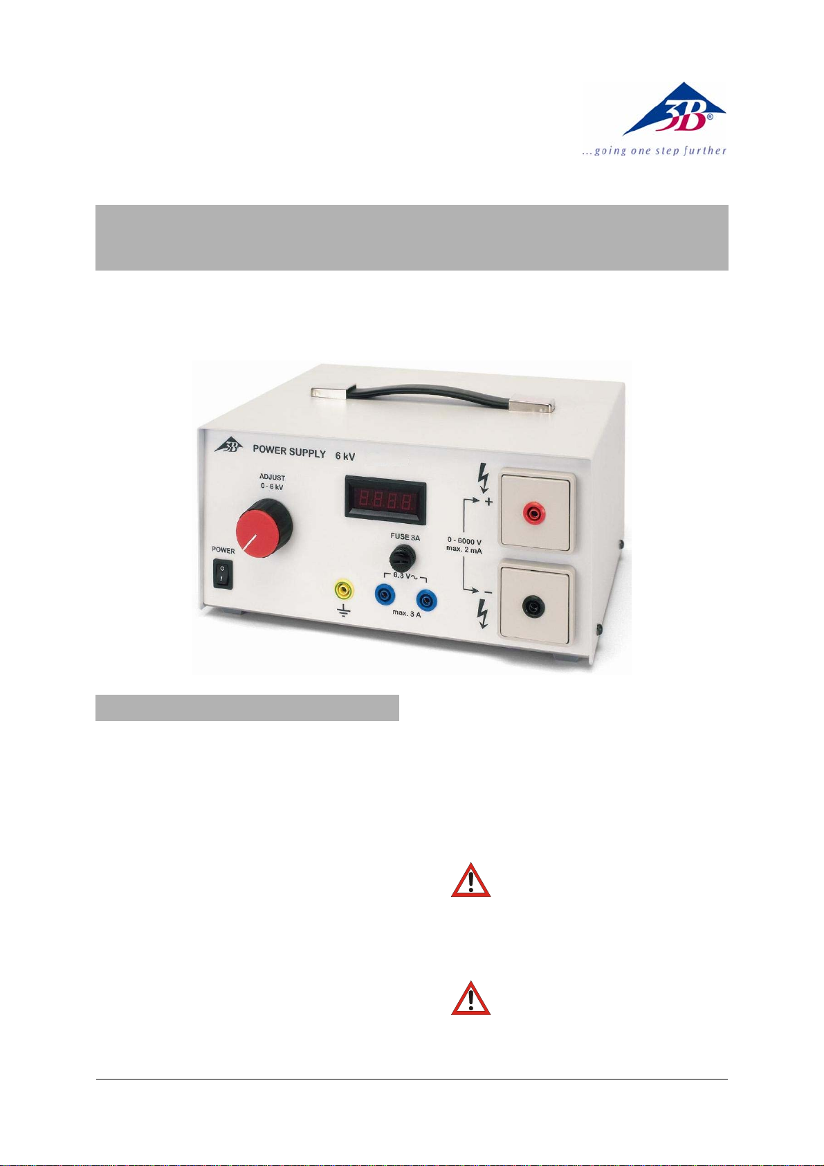
High Voltage Power Supply 6 kV (115 V, 50/60 Hz) 1003140
High Voltage Power Supply 6 kV (230 V, 50/60 Hz) 1003141
Instruction sheet
09/12 ALF
1. Safety instructions
The High Voltage Power Supply 6 kV conforms
to all safety regulations for electrical measuring,
control, monitoring and laboratory equipment, as
specified under DIN EN 61010, Section 1, and
the equipment has been designed to meet protection class I. It is intended for operation in a
dry environment, suitable for the operation of
electrical equipment and systems.
Safe operation of the equipment is guaranteed,
provided it is used correctly. However, there is
no guarantee of safety if the equipment is used
in an improper or careless manner.
If it may be assumed for any reason that nonhazardous operation will not be possible (e.g.
visible damage), the equipment should be
switched off immediately and secured against
any unintended use.
In schools and other educational institutions, the
operation of the power supply unit must be supervised by qualified personnel.
• Before using the power supply unit for the
first time, confirm that the specifications
printed on the rear side of the housing are
compatible with the local mains voltage.
• Before using the power supply unit, check
the housing and the mains lead for any
damage. In the event of any malfunction/operational defect or visible damage,
switch off the unit immediately and secure it
against unintended use.
•
•
Do not connect capacitors with a ca-
pacitance > 3.5 nF, as according to EN
61010-1 a danger of hazardous contact exists for capacitances above 4.5 nF (approximately 1 nF already exists in the power
supply output).
Do not connect another high voltage
(more than 500 V DC) between any of the
outputs and chassis/ground/earth!
1
Page 2
• The instrument may only be connected to
the mains via a socket that has an earth
connection.
• Do not connect multiple high-voltage power
supplies in series.
• Before making any connections, check the
experiment leads for damaged insulation and
exposed wires.
• Do not switch on the power supply before
the experiment set-up is finished and with
the voltage regulator turned all the way to
the left.
• Any changes to the circuit may only be
made with the power supply switched off.
• Replace a faulty fuse only with one matching
the specifications stated at the rear of the
housing.
• Disconnect the equipment from the mains
before replacing a fuse.
• Never short the fuse or the fuse holder.
• Do not put anything on top of the power
supply, that could prevent natural air cooling
of the device.
• The equipment may only be opened/repaired
by qualified and trained personnel.
2. Description
Universal, floating, high-voltage source for all
electrostatic experiments and for operating
spectral tubes as well as other gas-discharge
tubes and electronic tubes.
Equipped with an integrated transformer which
is resistant to high-voltages and which allows a
tapping of the heating voltage for operating electronic tubes.
Continuously adjustable, non-hazardous high
voltage with passive current limiting and a digital
voltage display.
The power supply unit with the order number
1003141 is for mains supplies of 230 V (±10%)
while the one with order no. 1003140 is for 115 V
(±10%) systems.
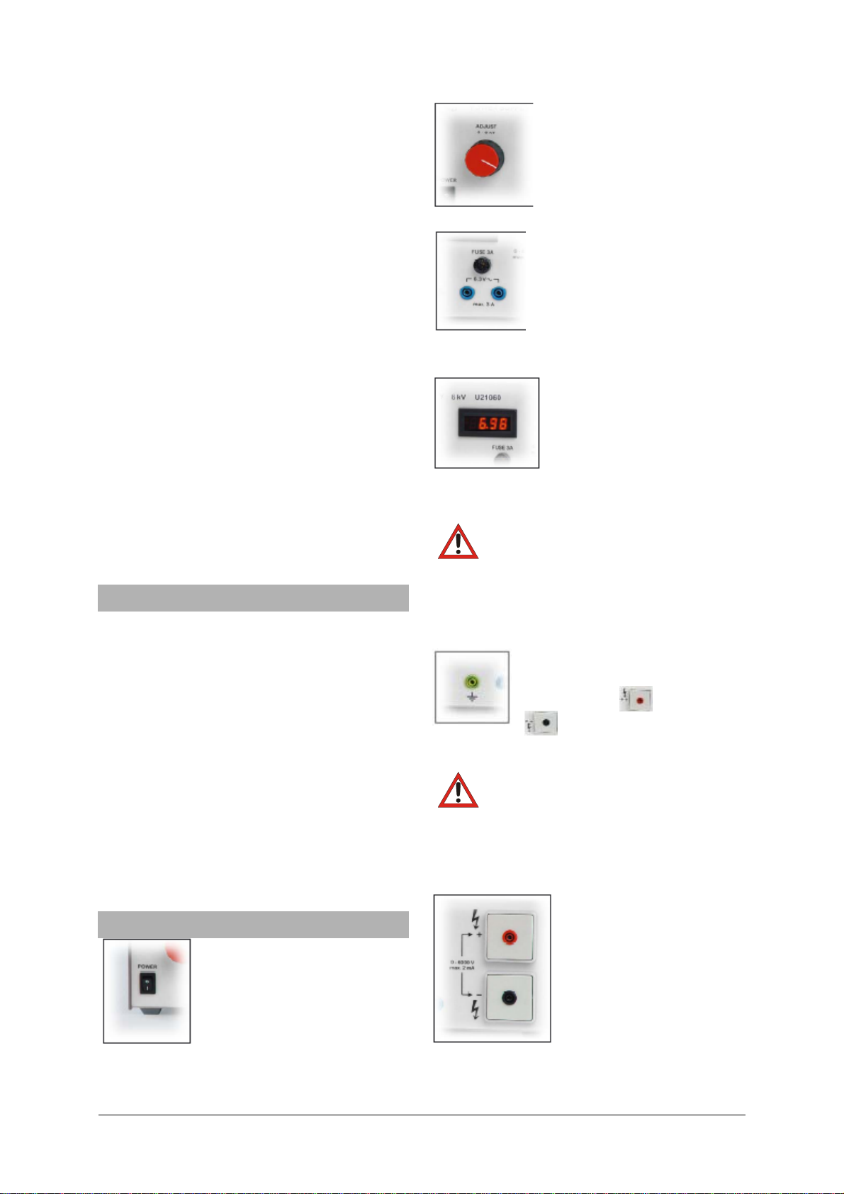
3. Bedienelemente
Mains switch
If the light in the display goes
out, remove the mains cable
and check the fuse in the fuse
holder on the rear panel of the
device.
Voltage regulator 0
0 6000 V DC
Continuous regulation with
digital voltmeter to the right.
Note: The Voltmeter displays
the voltage at the output.
Heater voltage output
6.3 V AC output, max. load 3 A.
If the voltage disappears, and the
LED-display is still on, there has
been an overload. Turn off the
device - unscrew the FUSE-cap
and replace the fuse (3 A slow blow).
Digital display
LED, 3 digits
Continuous reading of the
adjusted voltage at the output
under load.
Note: If the load current is 1 mA, then the max.
output voltage is approx. 3 kV. This is caused by
the safety passive current limiter
WARNING: The display may show a
small value if a load is connected, even if the
regulator knob is turned fully cw for maximum
output. If the load is changed the output may
rise to 6 kV without any warning.
Chassis/ground/earth
The outputs are floating with respect
to ground. The
output or the
output may be connected to
chassis/ground/earth. Then the digital LEDdisplay will be more stable.
Caution: Do not connect another high
voltage (more than 500 V DC) between any of
the outputs and chassis/ground/earth!!! - or the
internal transformer will be permanently damaged.
High voltage output
0 ... 6000 V DC, max 2 mA
load
Continuously adjustable.
Outputs are floating and the
positive or the negative
output should be connected
to the chassis/ground/earth.
An external voltage of
maximum 500 V DC may be added between any
of the outputs and chassis/ground/earth.
2
Page 3

Primary fuse/Mains input
Unscrew cap to replace fuse.
1003140: Mains input 115 V,
50/60 Hz
1003141: Mains input 230 V,
50/60 Hz
Power cable
US-type 5-15P/C13 for
power supply 1003140
Power cable
EU-type Schuko IEC-320/C13
for power supply 1003141
4. Technical data
Outputs:
High voltage output: 0 − 6000 V DC,
max. 2 mA
Heater voltage output: 6.3 V AC, max. 3 A,
high voltage resistant up to 6 kV
Overload protection: Feinsicherung 3 A,
träge
Terminals: 4 mm safety sockets
Power consumption: 50 VA
High-voltage display: 3-digit LED
Dimensions: 140x285x220 mm³
Weight: 6 kg approx.
5. Care and maintenance
• Before cleaning the equipment, disconnect it
from its power supply.
• Use a soft, damp cloth to clean it.
6. Disposal
• The packaging should be disposed of at
local recycling points.
• Should you need to dispose of the equip-
ment itself, never throw it away in normal
domestic waste. Local regulations for the
disposal of electrical equipment will apply.
3B Scientific GmbH ▪ Rudorffweg 8 ▪ 21031 Hamburg ▪ Germany ▪ www.3bscientific.com
Subject to technical amendments
© Copyright 2012 3B Scientific GmbH
Page 4

 Loading...