

Page 1
3B SCIENTIFIC® PHYSICS
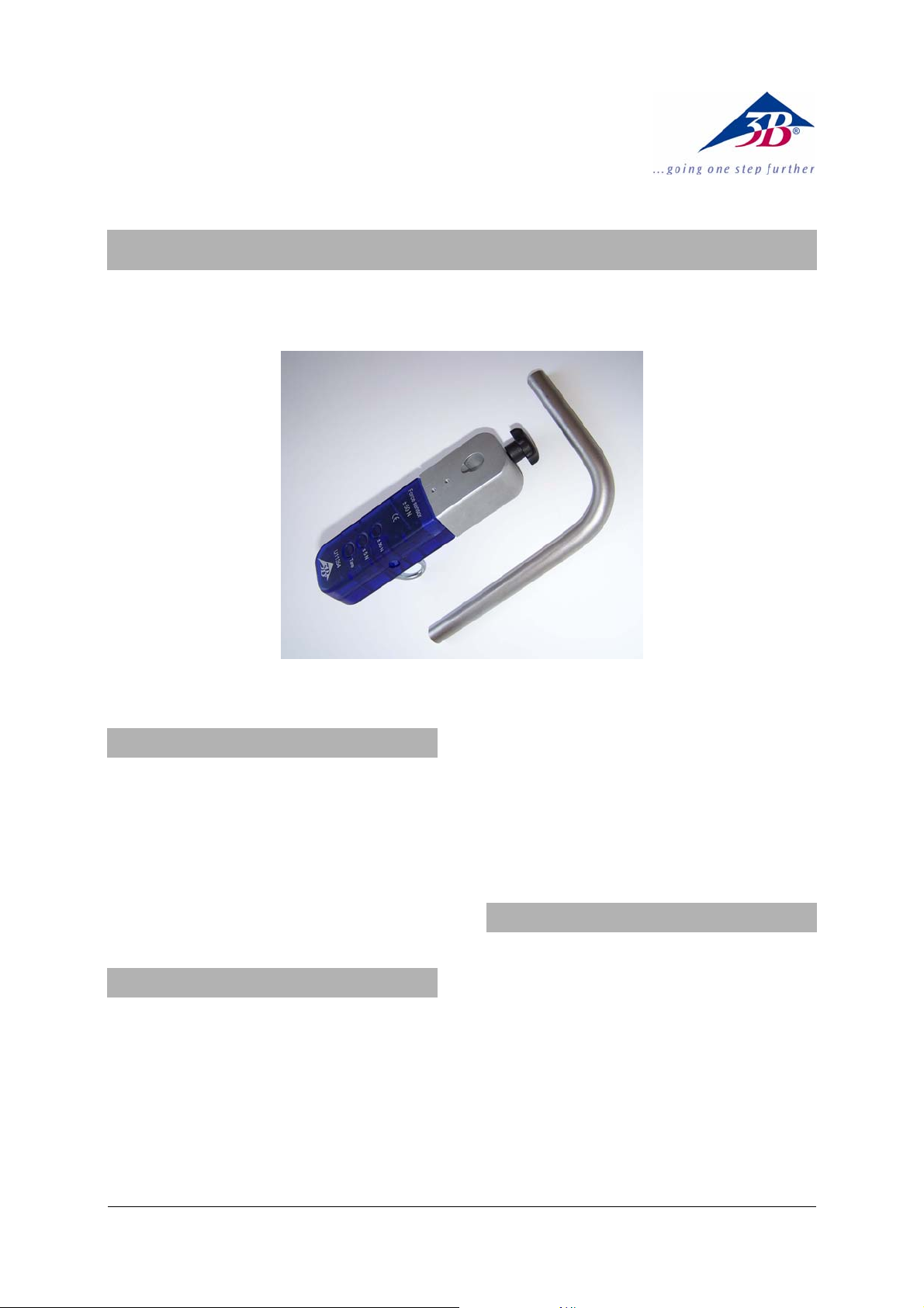
Force Sensor, ± 50 N U11354
Instruction Sheet
08/08 Hh
1. Safety instructions
• To avoid permanent damage to the integrated
load cell, do not exceed the maximum
permitted applied force of ± 150 N!
• Do not allow the sensor unit to fall onto a hard
surface from a height greater than 1 m!
• The ± 150 N force sensor must only be used for
educational purposes!
The ± 150 N force sensor is not suitable for safetyrelated applications!
2. Description
Sensor box incorporating a load cell and a force
sensor working on the foil strain-gauge principle.
Push-buttons allow a choice between two
measurement ranges, ± 5 N and ± 50 N.
The measurement range selected is indicated by an
LED beside the relevant button.
A tare function (compensation of the no-load
reading) is provided for both measurement ranges.
The bent clamping rod that is provided allows the
sensor box to be mounted at 90°.
The screw hook with M4 thread that is provided
can be replaced by any other attachment with an
M4 thread.
The sensor box is designed to be recognised
automatically by the 3B NETlog
3. Equipment supplied
1 Force sensor, ± 50 N
1 Clamping rod with 90° bend,
l
= 150 mm, l2 = 95 mm, d = 12 mm
1
1 Screw hook with M4 thread, eye diameter
20 mm
1 8-pin mini-DIN connecting cable, length 60 cm
1 Instruction sheet
TM
.
1
Page 2

4. Technical data
7. Sample experiments
Measurement ranges: 0 ... ± 5 N,
0 ... ± 50 N
Sensor type: load cell with foil strain-
gauge
Non-linearity: typically ± 0.04% of total
measurement range
Resolution: 0.01 N in 5 N range
0.1 N in 50 N range
Tare compensation: max. ± 50 N
Max. frequency: typically 20 Hz
Max. diameter of
supporting rod: 13 mm
5. Operation
• Place the sensor box near the experiment and
connect it to the point that will apply the
forces; if necessary use the bent clamping rod.
• Screw in the threaded hook if appropriate, or
alternatively replace it by another attachment
for applying force.
• Connect the sensor box to one of the two
analogue inputs (A or B) of the 3B NETlog
TM
using the mini-DIN cable provided.
• Wait for the sensor recognition message
(“Probe Detect”).
• Choose the appropriate measurement range.
• If necessary, press the tare button to apply
compensation.
The tare compensation depends on the position in
which the force sensor is used, and it must be reset
for each new experimental set-up!
• Carry out the force measurement and read the
force value in the display of the 3B NETlog
TM
.
6. Applications
Measurements on simple harmonic oscillations.
Observation of frictional forces.
Investigations of Hooke’s Law.
Measuring the forces on a truck on a track.
Investigation of the forces in pulley systems.
Measuring the acceleration in a damped massand-spring oscillating system
Equipment needed:
1 3B NETlog
1 3B NETlab
TM
U11300
TM
U11310
1 Force sensor, ± 50 N U11354
1 Tripod stand U13270
1 Stainless steel rod, 750 mm U15003
1 Helical spring, 5 N/m U8401010
1 100 g weight, from set of weights U30016
• Set up the experiment as shown in fig. 1.
• On the 3B NETlab
TM
, open the application
(template) for the experiment with the ± 50 N
force sensor.
• Attach the weight to the helical spring and
hang the spring on the force sensor. Ensure
that there is nothing hindering the oscillation
motion.
• Pass the connecting cable of the force sensor
over the sensor and coil it around the stand as
shown in Figure 1.
• Steady the weight by hand so that it is
motionless on the helical spring.
• Select the ± 5 N measurement range.
• Press the tare button of the force sensor and
set the pointer to zero in the display of the
3B NETlog
• Pull the weight down manually to the level of
TM
.
the stand base and release it.
• Start the recording of the force curve on the
3B NETlab
• Interpret and evaluate the curve.
TM
(see fig. 2).
2
Page 3

Fig. 1 Measuring the oscillations of a weakly-damped mass-and-spring system
Fig. 2 Oscillations of a weakly-damped mass-and-spring system displayed on the screen of the 3B NETlabTM (U11310)
3B Scientific GmbH • Rudorffweg 8 • 21031 Hamburg • Germany • www.3bscientific.com
Subject to technical amendments.
© Copyright 2007 3B Scientific GmbH
Page 4

 Loading...